Embed Size (px)
Citation preview

Xie, N. and Vassalos, D. and Sayer, P.G. (2007) The effect of lift on the
wave-making resistance of multi-hull craft. International Shipbuilding
Progress, 54 (2-3). ISSN 0020-868X ,
This version is available at https://strathprints.strath.ac.uk/9823/
Strathprints is designed to allow users to access the research output of the University of
Strathclyde. Unless otherwise explicitly stated on the manuscript, Copyright © and Moral Rights
for the papers on this site are retained by the individual authors and/or other copyright owners.
Please check the manuscript for details of any other licences that may have been applied. You
may not engage in further distribution of the material for any profitmaking activities or any
commercial gain. You may freely distribute both the url (https://strathprints.strath.ac.uk/) and the
content of this paper for research or private study, educational, or not-for-profit purposes without
prior permission or charge.
Any correspondence concerning this service should be sent to the Strathprints administrator:
The Strathprints institutional repository (https://strathprints.strath.ac.uk) is a digital archive of University of Strathclyde research
outputs. It has been developed to disseminate open access research outputs, expose data about those outputs, and enable the
management and persistent access to Strathclyde's intellectual output.
International Shipbuilding Progress 54 (2007) 83–95 83IOS Press
The effect of lift on the wave-making resistance of
multi-hull craft
Nan Xie ∗, Dracos Vassalos and Philip SayerDepartment of Naval Architecture and Marine Engineering, Universities of Glasgow and
Strathclyde, UK
A potential based panel method is presented to estimate the wave-making characteristics of multi-
hull craft. In order to simulate the lifting potential flow around the sub-hulls, the method adopts mixed
source/doublet distributions on the sub-hulls and their wake surface, while sources are distributed on
the main hull and the free surface. In this way, the asymmetric flow characteristics of the sub-hull are
properly simulated, i.e., a Kutta condition is satisfied at the trailing edge of the sub-hull. Comparison
is made between the numerical and model experimental measurements, and a good correlation has been
found. The wave-making characteristics and pressure distributions on the sub-hull predicted by the present
method can differ from those based on a distribution of sources alone, especially the pressure distributions
at the stern of the sub-hulls.
Keywords: Multi-hull craft, lift, panel method, potential flow, wave-making resistance
1. Introduction
Multi-hull ships (catamaran, trimaran, pentamaran, etc.) offer many hydrody-
namic and layout advantages, and are attractive options for ship designers. The in-
terference among the sub-hulls and the main hull can lead to optimal position of the
sub-hulls relating to the main hull to reduce wave-making resistance. Other advan-
tages are the larger deck area and increased stability. Practical tools for predicting
the wave-making resistance performance of these types are desirable for the design-
ers, especially at the initial design stage, where various options are to be evaluated.
The most widely used tools for such purposes are based on potential panel methods.
In many cases, the sub-hulls experience a lateral lifting force due to the asymmetric
flow about the central plane of the sub-hulls; therefore, a Kutta condition should be
imposed at the trailing edge. In tackling the steady wave-making problem of multi-
hull craft, many researchers have adopted the Kelvin source technique in which the
Green function satisfies the linear free surface condition and far-field radiation condi-
tion, but is unable to satisfy the Kutta condition at the trailing edge; see, for example,
*Corresponding author: Nan Xie, 100 Montrose Street, Henry Dyer Building, Glasgow G4 0LZ, UK.
E-mail: [email protected]; [email protected]
0020-868X/07/$17.00 2007 – IOS Press and the authors. All rights reserved
84 N. Xie et al. / The effect of lift on the wave-making resistance of multi-hull craft
Yang, Noblesse, Lohner and Hendrix [1]. In the analysis of a 3D lifting body with
a free surface, Lee and Joo [2] used a mixed source and doublet distribution on the
body surface and a distribution of sources on the free surface to calculate the wave-
making resistance of a catamaran; a Dirichlet-type body boundary condition was
used on the body surface. In their formulations, the source strength on body surface
was set equal to the component of incoming flow velocity in normal direction to the
body surface; the induced velocity of the source distribution on the free surface was
not included, and so the body boundary condition was not satisfied exactly. They
strongly recommended checking normal velocity component on body surface. Lars-
son and Janson developed a 3D panel method for yacht and trimaran potential flow
[3,4]. In their method, sources and doublets were distributed on the lifting part of
the craft. The use of a Neumann boundary condition (where the normal component
of velocity is zero) leads to fewer equations than the unknown strengths of source
and doublet. In order to achieve closure, the lifting body surface can be divided into
strips, essentially parallel to the undisturbed flow direction. At each strip, the doublet
strength is assumed constant spanwise and varies linearly with the arc length from
the trailing edge of the pressure side around the nose, back to the trailing edge on the
suction side. Behind the trailing edge, several wake panels are added along which
the doublet strength is constant. The Kutta condition is satisfied by prescribing a di-
rection of the flow immediately behind the trailing edge, where the velocity vector is
assumed to be in the bisector plane. Numerically, this is accomplished by specifying
the normal to the surface and setting the velocity in this direction to be zero. This
turns out to be exactly the same condition as the hull surface condition, so Kutta
equations are of exactly the same form as the hull condition. However, a problem
arises in calculating the induced velocity of the doublet on the lifting body surface
and the Kutta panels. Xie and Vassalos [5] adopted source and doublet distributions
on the body surface and source distribution on the free surface to analyse perfor-
mance of a 3D hydrofoil under a free surface; the doublet strength on the lifting
body does not necessarily vary linearly with the arc length. Using an alternative ap-
proach, Suzuki, Nakata, Ikehata and Kai [6], and Zou and Soding [7] distributed
doublets on the central plane of the lifting body, while sources were distributed on
the hull surface. Chen and Liu [8] distributed doublets on a sub-surface inside the
lifting body (‘de-singularity’ method).
In the analysis of hydrodynamic performance of multi-hull craft, the source distri-
bution only method has a relatively simple mathematical formulations, however, this
method is unable to satisfy Kutta condition (with finite velocity at the trailing edge of
the sub-hulls). The prescript distribution of doublet (linear distribution along the arc
length of the lifting bodies) may be not suitable for general 3D flow cases. While the
method of distributing doublets on the central plane of the lifting body is appropriate
for thin lifting body cases. In the present paper, a potential based panel method is de-
veloped to predict wave-making characteristics of multi-hull craft. The free surface
boundary condition is linearised for the double-body flow potential. The total veloc-
ity potential is split into the double body flow and the disturbance flow potential. On
N. Xie et al. / The effect of lift on the wave-making resistance of multi-hull craft 85
the surface of lifting body (sub-hulls), a Dirichlet-type boundary condition is applied
to a distribution of sources and doublets. A distribution of doublets alone is deployed
on the wake surface of the sub-hulls, whereas sources are distributed on the main hull
surface and on the free surface. Numerical results of a catamaran are compared with
some published model test experimental measurements, a good agreement has been
found. Some numerical predictions are presented for two trimaran configurations;
these are compared against those using a distribution of sources. It is found that
wave-making characteristics and pressure distributions on the sub-hulls predicted
with the two methods are different, especially pressure distribution at the stern part
of the sub-hulls.
2. Mathematical formulations
Potential flow theory will be used in the present study, which means that the fluid
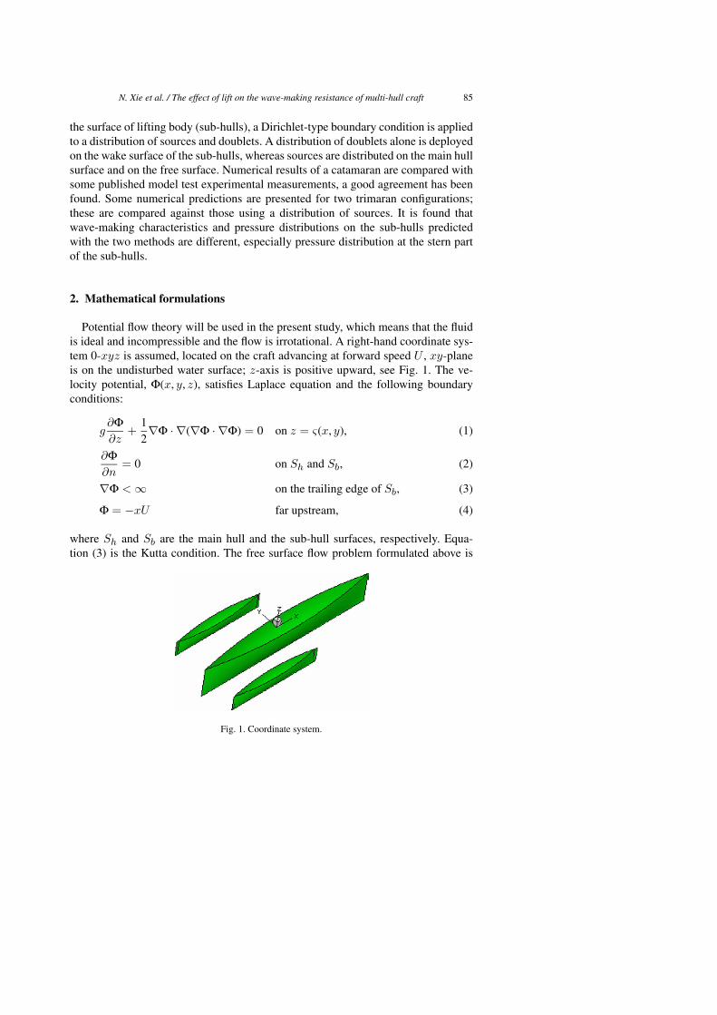
is ideal and incompressible and the flow is irrotational. A right-hand coordinate sys-
tem 0-xyz is assumed, located on the craft advancing at forward speed U , xy-plane
is on the undisturbed water surface; z-axis is positive upward, see Fig. 1. The ve-
locity potential, Φ(x, y, z), satisfies Laplace equation and the following boundary
conditions:
g∂Φ
∂z+
1
2∇Φ · ∇(∇Φ · ∇Φ) = 0 on z = ς(x, y), (1)
∂Φ
∂n= 0 on Sh and Sb, (2)
∇Φ < ∞ on the trailing edge of Sb, (3)
Φ = −xU far upstream, (4)
where Sh and Sb are the main hull and the sub-hull surfaces, respectively. Equa-
tion (3) is the Kutta condition. The free surface flow problem formulated above is
Fig. 1. Coordinate system.
86 N. Xie et al. / The effect of lift on the wave-making resistance of multi-hull craft
nonlinear, due to the free surface boundary condition and the unknown position of
the corresponding boundary. In the present study, the velocity potential is split into
the double body flow (φ) and the disturbance flow (ϕ) potentials:
Φ(x, y, z) = φ(x, y, z) + ϕ(x, y, z). (5)
It is assumed that the disturbance flow is much less than the double body flow. The
nonlinear free surface condition (1) is expanded on the free surface corresponding to
the double body flow, and it is further expanded at the undisturbed free surface (i.e.,
z = 0). The linearised free surface condition is therefore:
∇φ · ∇(∇φ · ∇ϕ) +1
2∇ϕ · ∇(∇φ · ∇φ) + gϕz − φzz∇φ · ∇ϕ
= −1
2∇φ · ∇(∇φ · ∇φ) −
1
2φzz(U2
−∇φ · ∇φ). (6)
The solution of the double body flow can be written in terms of velocity potentials
due to the disturbances of the main hull and the sub-hulls, and the incoming flows:
φ(x, y, z) = φh(x, y, z) + φb(x, y, z) + φ∞. (7)
Sources are distributed on the main hull surface; sources/doublets are distributed on
the sub-hull surface and doublets are distributed on the wake surface as well. These
velocity potentials are expressed as:
φh(x, y, z) =
∫∫
Sh
σ0
rds, (8)
φb(x, y, z) =1
4π
∫∫
Sb
[
1
r
∂φb
∂n− φb
∂
∂n
1
r
]
ds
−1
4π
∫∫
Sw
[
(φ+
b − φ−
b )∂
∂n
1
r
]
ds (9)
and φ∞ = −xU , where Sw is the wake surface of the sub-hulls, φ+
b and φ−
b are the
velocity potentials of suction side and pressure side of the trailing edge of Sb. When
the field point is on the sub-hull surface, (9) becomes:
2πφb +
∫∫
Sb−Sε
[
φb∂
∂n
1
r
]
ds +
∫∫
Sw
[
(φ+
b − φ−
b )∂
∂n
1
r
]
ds
+
∫∫
Sb
∂φh
∂n
1
rds =
∫∫
Sb
Unx
rds, (10)
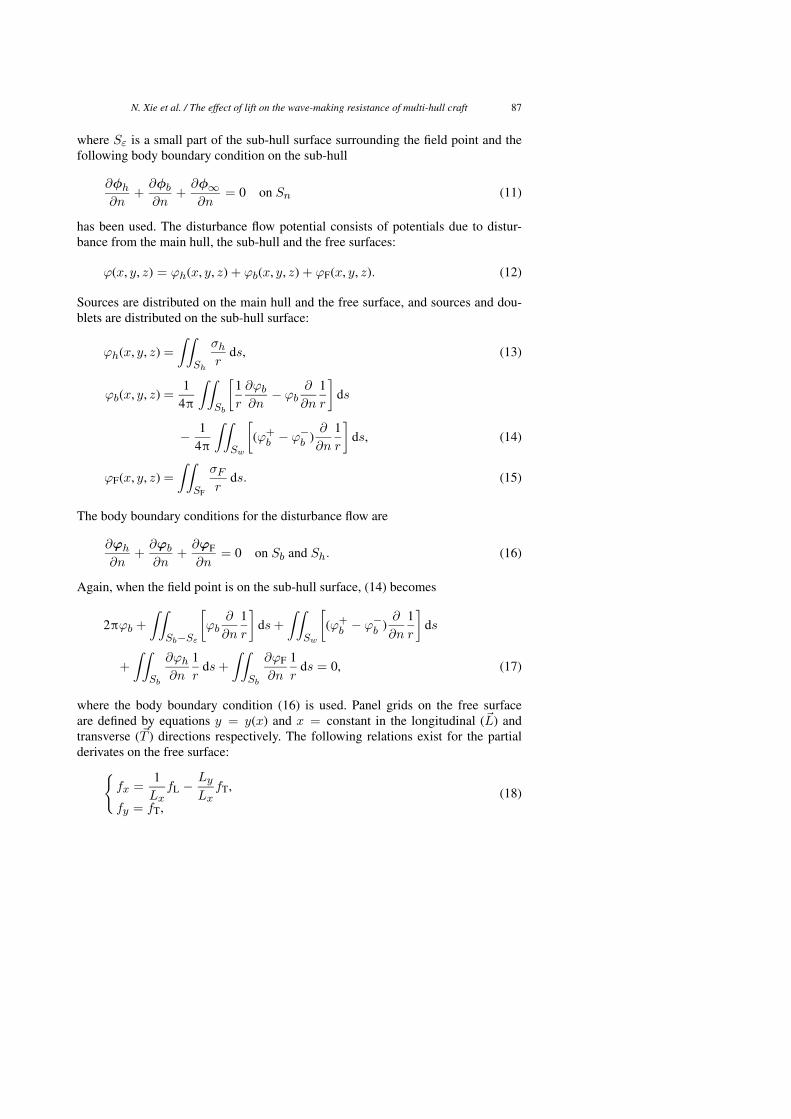
N. Xie et al. / The effect of lift on the wave-making resistance of multi-hull craft 87
where Sε is a small part of the sub-hull surface surrounding the field point and thefollowing body boundary condition on the sub-hull
∂φh
∂n+
∂φb
∂n+
∂φ∞
∂n= 0 on Sn (11)
has been used. The disturbance flow potential consists of potentials due to distur-bance from the main hull, the sub-hull and the free surfaces:
ϕ(x, y, z) = ϕh(x, y, z) + ϕb(x, y, z) + ϕF(x, y, z). (12)
Sources are distributed on the main hull and the free surface, and sources and dou-blets are distributed on the sub-hull surface:
ϕh(x, y, z) =
∫∫
Sh
σh
rds, (13)
ϕb(x, y, z) =1
4π
∫∫
Sb
[
1
r
∂ϕb
∂n− ϕb
∂
∂n
1
r
]
ds
−1
4π
∫∫
Sw
[
(ϕ+
b − ϕ−
b )∂
∂n
1
r
]
ds, (14)
ϕF(x, y, z) =
∫∫
SF
σF
rds. (15)
The body boundary conditions for the disturbance flow are
∂ϕh
∂n+
∂ϕb
∂n+
∂ϕF
∂n= 0 on Sb and Sh. (16)
Again, when the field point is on the sub-hull surface, (14) becomes
2πϕb +
∫∫
Sb−Sε
[
ϕb∂
∂n
1
r
]
ds +
∫∫
Sw
[
(ϕ+
b − ϕ−
b )∂
∂n
1
r
]
ds
+
∫∫
Sb
∂ϕh
∂n
1
rds +
∫∫
Sb
∂ϕF
∂n
1
rds = 0, (17)
where the body boundary condition (16) is used. Panel grids on the free surfaceare defined by equations y = y(x) and x = constant in the longitudinal (�L) andtransverse (�T ) directions respectively. The following relations exist for the partialderivates on the free surface:
{
fx =1
LxfL −
Ly
LxfT,
fy = fT,(18)
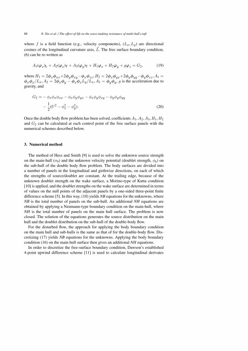
88 N. Xie et al. / The effect of lift on the wave-making resistance of multi-hull craft
where f is a field function (e.g., velocity components), (Lx, Ly) are directional
cosines of the longitudinal curvature axis, �L. The free surface boundary condition,
(6) can be re-written as
A1(ϕx)L + A2(ϕx)T + A3(ϕy)T + H1ϕx + H2ϕy + gϕz = G2, (19)
where H1 = 2φxφxx+2φyφxy−φxφzz , H2 = 2φxφyx+2φyφyy−φyφzz , A1 =
φxφx/Lx, A2 = 2φxφy − φxφxLy/Lx, A3 = φyφy , g is the acceleration due to
gravity, and
G2 = − φxφxφxx − φxφyφyx − φxφyφxy − φyφyφyy
−1
2(U2
− φ2x − φ2
y). (20)
Once the double body flow problem has been solved, coefficients A1, A2, A3, H1, H2
and G2 can be calculated at each control point of the free surface panels with the
numerical schemes described below.
3. Numerical method
The method of Hess and Smith [9] is used to solve the unknown source strength
on the main-hull (σ0) and the unknown velocity potential (doublet strength, φb) on
the sub-hull of the double body flow problem. The body surfaces are divided into
a number of panels in the longitudinal and girthwise directions, on each of which
the strengths of source/doublet are constant. At the trailing edge, because of the
unknown doublet strength on the wake surface, a Morino-type of Kutta condition
[10] is applied, and the doublet strengths on the wake surface are determined in terms
of values on the null points of the adjacent panels by a one-sided three-point finite
difference scheme [5]. In this way, (10) yields NB equations for the unknowns, where
NB is the total number of panels on the sub-hull. An additional NH equations are
obtained by applying a Neumann-type boundary condition on the main-hull, where
NH is the total number of panels on the main hull surface. The problem is now
closed. The solution of the equations generates the source distribution on the main
hull and the doublet distribution on the sub-hull of the double-body flow.
For the disturbed flow, the approach for applying the body boundary condition
on the main hull and sub-hulls is the same as that of for the double-body flow. Dis-
cretizing (17) yields NB equations for the unknowns. Applying the body boundary
condition (16) on the main hull surface then gives an additional NH equations.
In order to discretize the free-surface boundary condition, Dawson’s established
4-point upwind difference scheme [11] is used to calculate longitudinal derivates
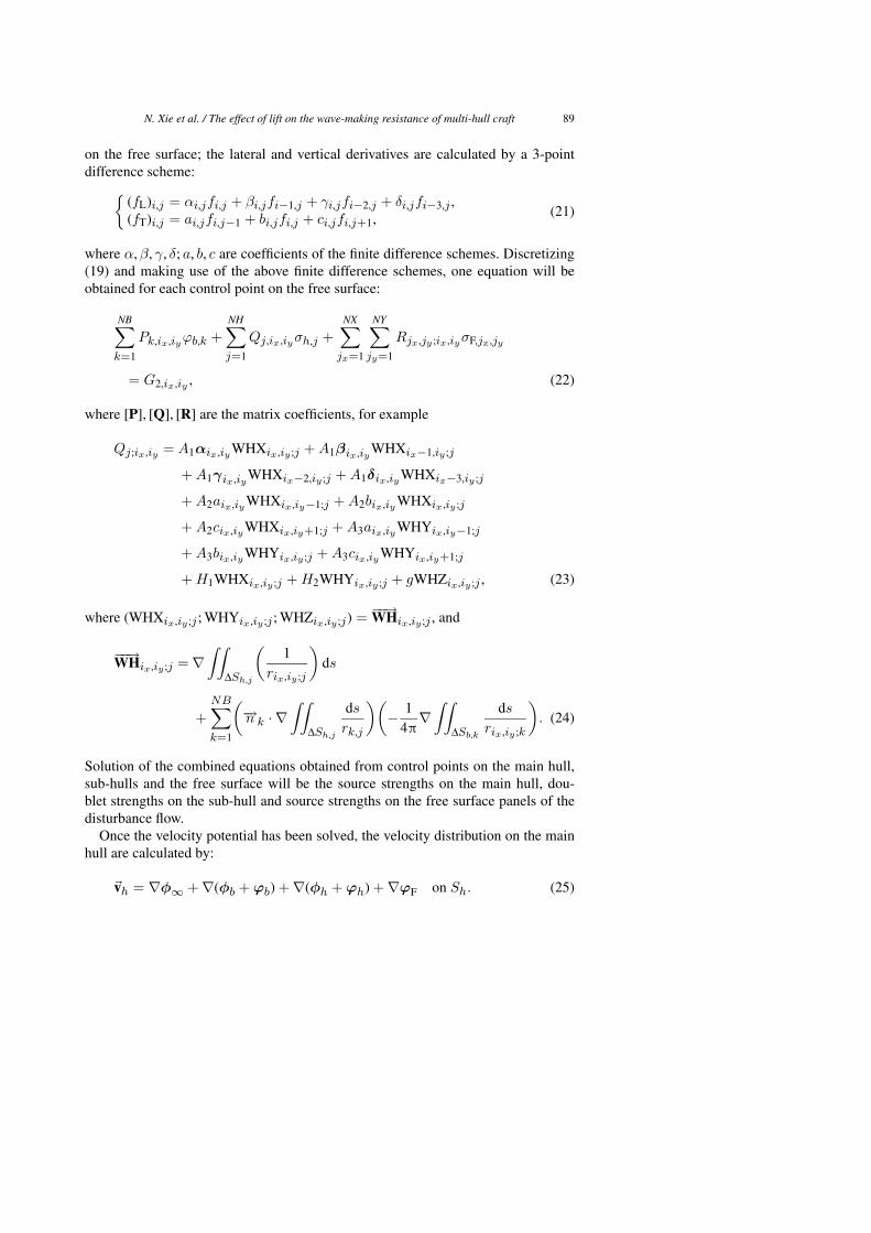
N. Xie et al. / The effect of lift on the wave-making resistance of multi-hull craft 89
on the free surface; the lateral and vertical derivatives are calculated by a 3-point
difference scheme:
{
(fL)i,j = αi,jfi,j + βi,jfi−1,j + γi,jfi−2,j + δi,jfi−3,j ,
(fT)i,j = ai,jfi,j−1 + bi,jfi,j + ci,jfi,j+1,(21)
where α, β, γ, δ; a, b, c are coefficients of the finite difference schemes. Discretizing
(19) and making use of the above finite difference schemes, one equation will be
obtained for each control point on the free surface:
NB∑
k=1
Pk,ix,iyϕb,k +
NH∑
j=1
Qj,ix,iyσh,j +
NX∑
jx=1
NY∑
jy=1
Rjx,jy ;ix,iyσF,jx,jy
= G2,ix,iy , (22)
where [P], [Q], [R] are the matrix coefficients, for example
Qj;ix,iy = A1αix,iy WHXix,iy ;j + A1βix,iy WHXix−1,iy ;j
+ A1γix,iy WHXix−2,iy ;j + A1δix,iy WHXix−3,iy ;j
+ A2aix,iy WHXix,iy−1;j + A2bix,iy WHXix,iy ;j
+ A2cix,iy WHXix,iy+1;j + A3aix,iy WHYix,iy−1;j
+ A3bix,iy WHYix,iy ;j + A3cix,iy WHYix,iy+1;j
+ H1WHXix,iy ;j + H2WHYix,iy ;j + gWHZix,iy ;j , (23)
where (WHXix,iy ;j ; WHYix,iy ;j ; WHZix,iy ;j) =−−→WHix,iy ;j , and
−−→WHix,iy ;j = ∇
∫∫
∆Sh,j
(
1
rix,iy ;j
)
ds
+
NB∑
k=1
(
−→n k · ∇
∫∫
∆Sh,j
ds
rk,j
)(
−1
4π
∇
∫∫
∆Sb,k
ds
rix,iy ;k
)
. (24)
Solution of the combined equations obtained from control points on the main hull,
sub-hulls and the free surface will be the source strengths on the main hull, dou-
blet strengths on the sub-hull and source strengths on the free surface panels of the
disturbance flow.
Once the velocity potential has been solved, the velocity distribution on the main
hull are calculated by:
�vh = ∇φ∞
+ ∇(φb + ϕb) + ∇(φh + ϕh) + ∇ϕF on Sh. (25)
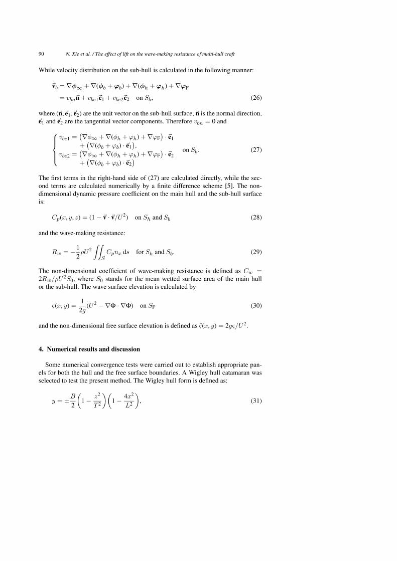
90 N. Xie et al. / The effect of lift on the wave-making resistance of multi-hull craft
While velocity distribution on the sub-hull is calculated in the following manner:
�vb = ∇φ∞
+ ∇(φb + ϕb) + ∇(φh + ϕh) + ∇ϕF
= vbn�n + vbe1�e1 + vbe2�e2 on Sb, (26)
where (�n,�e1,�e2) are the unit vector on the sub-hull surface, �n is the normal direction,�e1 and�e2 are the tangential vector components. Therefore vbn = 0 and
vbe1 =(
∇φ∞ + ∇(φh + ϕh) + ∇ϕF
)
·�e1
+(
∇(φb + ϕb) ·�e1
)
,
vbe2 =(
∇φ∞ + ∇(φh + ϕh) + ∇ϕF
)
·�e2
+(
∇(φb + ϕb) ·�e2
)
on Sb. (27)
The first terms in the right-hand side of (27) are calculated directly, while the sec-
ond terms are calculated numerically by a finite difference scheme [5]. The non-
dimensional dynamic pressure coefficient on the main hull and the sub-hull surface
is:
Cp(x, y, z) = (1 −�v ·�v/U2) on Sh and Sb (28)
and the wave-making resistance:
Rw = −1
2ρU2
∫∫
SCpnx ds for Sh and Sb. (29)
The non-dimensional coefficient of wave-making resistance is defined as Cw =
2Rw/ρU2S0, where S0 stands for the mean wetted surface area of the main hull
or the sub-hull. The wave surface elevation is calculated by
ς(x, y) =1
2g(U2
−∇Φ · ∇Φ) on SF (30)
and the non-dimensional free surface elevation is defined as ς̃(x, y) = 2gς/U2.
4. Numerical results and discussion
Some numerical convergence tests were carried out to establish appropriate pan-
els for both the hull and the free surface boundaries. A Wigley hull catamaran was
selected to test the present method. The Wigley hull form is defined as:
y = ±B
2
(
1 −z2
T 2
)(
1 −4x2
L2
)
, (31)
N. Xie et al. / The effect of lift on the wave-making resistance of multi-hull craft 91
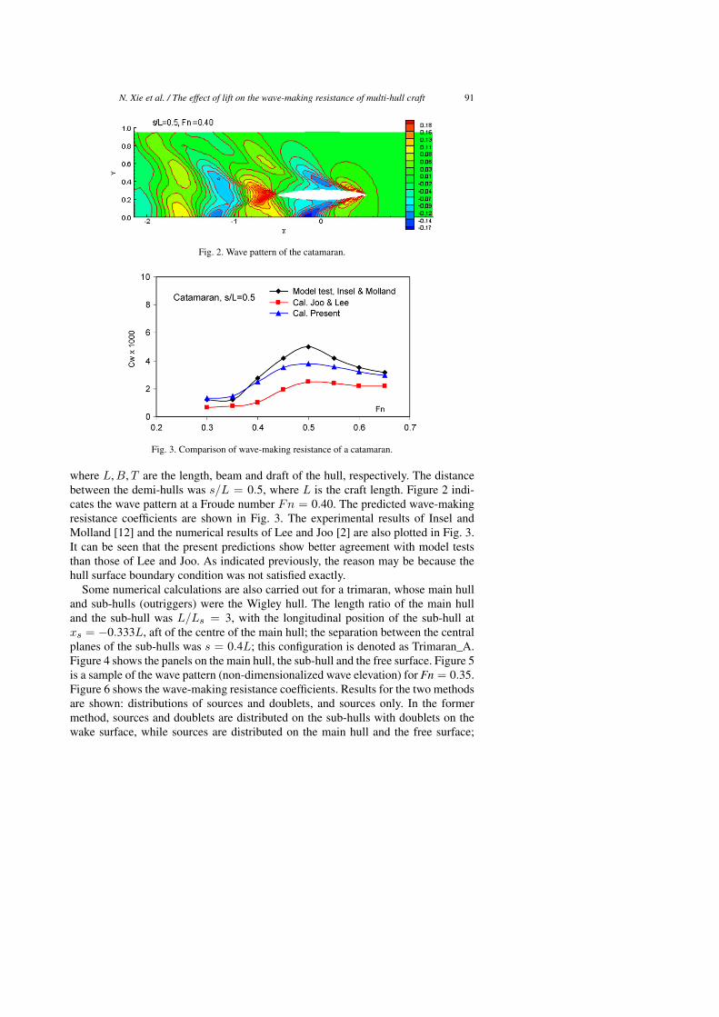
Fig. 2. Wave pattern of the catamaran.
Fig. 3. Comparison of wave-making resistance of a catamaran.
where L, B, T are the length, beam and draft of the hull, respectively. The distance
between the demi-hulls was s/L = 0.5, where L is the craft length. Figure 2 indi-
cates the wave pattern at a Froude number Fn = 0.40. The predicted wave-making
resistance coefficients are shown in Fig. 3. The experimental results of Insel and
Molland [12] and the numerical results of Lee and Joo [2] are also plotted in Fig. 3.
It can be seen that the present predictions show better agreement with model tests
than those of Lee and Joo. As indicated previously, the reason may be because the
hull surface boundary condition was not satisfied exactly.
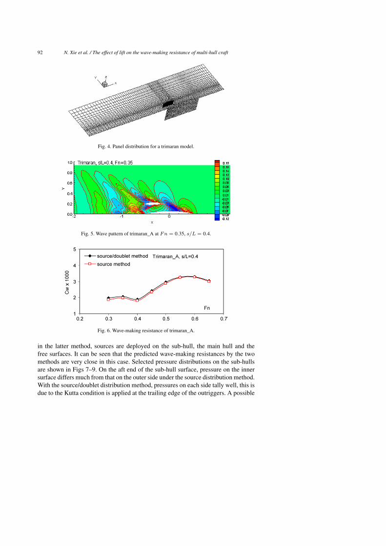
Some numerical calculations are also carried out for a trimaran, whose main hull
and sub-hulls (outriggers) were the Wigley hull. The length ratio of the main hull
and the sub-hull was L/Ls = 3, with the longitudinal position of the sub-hull at
xs = −0.333L, aft of the centre of the main hull; the separation between the central
planes of the sub-hulls was s = 0.4L; this configuration is denoted as Trimaran_A.
Figure 4 shows the panels on the main hull, the sub-hull and the free surface. Figure 5
is a sample of the wave pattern (non-dimensionalized wave elevation) for Fn = 0.35.
Figure 6 shows the wave-making resistance coefficients. Results for the two methods
are shown: distributions of sources and doublets, and sources only. In the former
method, sources and doublets are distributed on the sub-hulls with doublets on the
wake surface, while sources are distributed on the main hull and the free surface;
92 N. Xie et al. / The effect of lift on the wave-making resistance of multi-hull craft
Fig. 4. Panel distribution for a trimaran model.
Fig. 5. Wave pattern of trimaran_A at Fn = 0.35, s/L = 0.4.
Fig. 6. Wave-making resistance of trimaran_A.
in the latter method, sources are deployed on the sub-hull, the main hull and the
free surfaces. It can be seen that the predicted wave-making resistances by the two
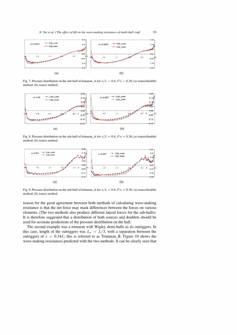
methods are very close in this case. Selected pressure distributions on the sub-hulls
are shown in Figs 7–9. On the aft end of the sub-hull surface, pressure on the inner
surface differs much from that on the outer side under the source distribution method.
With the source/doublet distribution method, pressures on each side tally well, this is
due to the Kutta condition is applied at the trailing edge of the outriggers. A possible
N. Xie et al. / The effect of lift on the wave-making resistance of multi-hull craft 93
Fig. 7. Pressure distribution on the sub-hull of trimaran_A for s/L = 0.6, Fn = 0.30; (a) source/doublet
method; (b) source method.
Fig. 8. Pressure distribution on the sub-hull of trimaran_A for s/L = 0.6, Fn = 0.30; (a) source/doublet
method; (b) source method.
Fig. 9. Pressure distribution on the sub-hull of trimaran_A for s/L = 0.6, Fn = 0.30; (a) source/doublet
method; (b) source method.
reason for the good agreement between both methods of calculating wave-making
resistance is that the net force may mask differences between the forces on various
elements. (The two methods also produce different lateral forces for the sub-hulls).
It is therefore suggested that a distribution of both sources and doublets should be
used for accurate predictions of the pressure distribution on the hull.
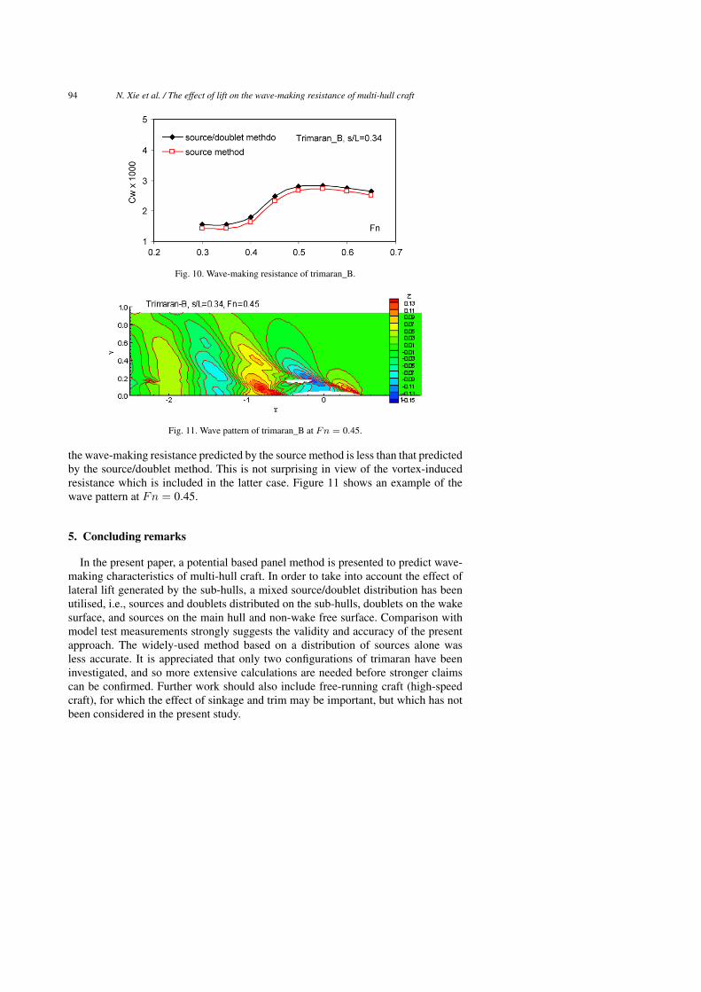
The second example was a trimaran with Wigley demi-hulls as its outriggers. In
this case, length of the outriggers was Ls = L/3, with a separation between the
outriggers of s = 0.34L; this is referred to as Trimaran_B. Figure 10 shows the
wave-making resistances predicted with the two methods. It can be clearly seen that
94 N. Xie et al. / The effect of lift on the wave-making resistance of multi-hull craft
Fig. 10. Wave-making resistance of trimaran_B.
Fig. 11. Wave pattern of trimaran_B at Fn = 0.45.
the wave-making resistance predicted by the source method is less than that predictedby the source/doublet method. This is not surprising in view of the vortex-inducedresistance which is included in the latter case. Figure 11 shows an example of thewave pattern at Fn = 0.45.
5. Concluding remarks
In the present paper, a potential based panel method is presented to predict wave-making characteristics of multi-hull craft. In order to take into account the effect oflateral lift generated by the sub-hulls, a mixed source/doublet distribution has beenutilised, i.e., sources and doublets distributed on the sub-hulls, doublets on the wakesurface, and sources on the main hull and non-wake free surface. Comparison withmodel test measurements strongly suggests the validity and accuracy of the presentapproach. The widely-used method based on a distribution of sources alone wasless accurate. It is appreciated that only two configurations of trimaran have beeninvestigated, and so more extensive calculations are needed before stronger claimscan be confirmed. Further work should also include free-running craft (high-speedcraft), for which the effect of sinkage and trim may be important, but which has notbeen considered in the present study.
N. Xie et al. / The effect of lift on the wave-making resistance of multi-hull craft 95
References
[1] C. Yang, F. Noblesse, R. Lohner and D. Hendrix, Practical CFD applications to design of a wave
cancellation multihull ship, in: Proceedings of 23rd Symposium on Naval Hydrodynamics, 2000,
pp. 200–222.
[2] S.J. Lee and Y.R. Joo, Calculation of wave making resistance of high-speed catamaran using a panel
method, in: Proceedings of Third Korea–Japan Joint Workshop on Ship and Marine Hydrodynamics,
1996, pp. 10–17.
[3] L. Larsson, C.E. Janson and P. Brun, A numerical investigation of trimaran configurations, in: Pro-
ceedings of FAST’97 Conference, 1997, pp. 537–544.
[4] L. Larsson and C.E. Janson, Potential flow calculations for sailing yachts, in: CFD for Ship and
Offshore Design, 31st WEGEMT School, Hamburg, 1999, pp. 1–30.
[5] N. Xie and D. Vassalos, Performance analysis of 3D hydrofoil under free surface, Ocean Engineering
34(8/9) (2007), 1257–1264.
[6] K. Suzuki, Y. Nakata, M. Ikehata and H. Kai, Numerical prediction on wave making resistance of
high speed trimaran, in: Proceedings of FAST’97 Conference, 1997, pp. 611–621.
[7] Z. Zou and H. Soding, A panel method for lifting potential flows around three-dimensional surface-
piercing bodies, in: Proceedings of 20th Symposium on Naval Hydrodynamics, Santa Barbara, 1994,
pp. 801–821.
[8] C.K. Chen and H. Liu, A submerged vortex lattice method for calculation of the flow around three-
dimensional hydrofoil, Journal of Ship Mechanics 9(2) (2005), 41–45.
[9] J.L. Hess and A.M.O. Smith, Calculation of non-lifting potential flow about arbitrary three-
dimensional bodies, Journal of Ship Research 8(2) (1964), 22–44.
[10] L. Morino and C.C. Kuo, Subsonic potential aerodynamics for complex configurations, a general
theory, AIAA J. 12(2) (1974), 191–197.
[11] C.W. Dawson, A practical computer method for solving ship wave problems, in: Proceedings of 2nd
International Conference on Numerical Ship Hydrodynamics, 1977, pp. 30–38.
[12] M. Insel and A.F. Molland, An investigation into the resistance components of high speed displace-
ment catamarans, in: Trans. RINA, 1991, pp. 1–20.


![[Derek Sayer] Marx's Method Ideology, Science, An(BookZZ.org)](https://img.pdfslide.us/doc/110x75/563dbba7550346aa9aaf145e/derek-sayer-marxs-method-ideology-science-anbookzzorg.jpg)