Embed Size (px)
Citation preview

XFX Motherboard Installation Manual
Version: 1.0
Table of Contents Chapter 1 Product Introduction Highlight Features....................................................................................................................................... 2 Main Features.............................................................................................................................................. 3 Layout ….....................................................................................................................................................5 Rear Panel Ports ..........................................................................................................................................6 Chapter 2 Installation Instructions CPU............................................................................................................................................................10 Memory .....................................................................................................................................................13 Expansion Slots .........................................................................................................................................15 Connectors ................................................................................................................................................16 Power Supply............................................................................................................................................ 18 Jumpers .....................................................................................................................................................19 Chapter 3 BIOS Description Enter BIOS Setup ......................................................................................................................................21 Main menu ................................................................................................................................................21 Standard CMOS Features .........................................................................................................................23 Advanced BIOS Features ..........................................................................................................................25 Advanced Chipset Features .......................................................................................................................27 Integrated Peripherals ...............................................................................................................................35 Power Management Setup ........................................................................................................................37 PnP/PCI Configurations ............................................................................................................................38 System Monitor .........................................................................................................................................39 Load Defaults ............................................................................................................................................41 Set Password .............................................................................................................................................41 Set User Name ..........................................................................................................................................41 Save & Exit Setup......................................................................................................................................42 Exit Without Saving...................................................................................................................................42 Chapter 4 Raid Setup and LED Error Codes Setting up Raid in the BIOS…………………………………………………………………………..….46 Configuring Raid in Nvidia Raid Utility………………………………………………………………...46 Installing the Raid Driver (for bootable Raid Array)…………………………………………...………..47 On board LED error codes…………………………………………………………………...…………..49 Appendix………………………………………………………………………………..……………….54

Attention: Safety Information
• Make sure your power supply is turned off and disconnect the power cable from the electri-cal outlet before inserting or removing expansion cards or other peripherals, especially when you insert or remove a memory module. Failure to turn off the power supply may result in serious damage to your system or memory module.
• Make sure that your power supply is set to the correct voltage in your area. If you are not
sure about the voltage of the electrical outlet you are using, contact your local power com-pany.
• Keep paper clips, stables, or any conductive objects away from connectors, slots, sockets
and the board to avoid short circuits. • Make sure you attach the CPU and heatsink using thermally conductive compound to ensure
full contact. • It is suggested to select high-quality, certified fans in order to avoid damage to the mother-
board and CPU due high temperatures. Never turn on the system if the CPU fan is not prop-erly installed.
Attention:
• We cannot guarantee that your system will operate normally while over-clocked. Normal operation depends on the over-clock capacity of your device.
• Since BIOS programs are upgraded from time to time, the BIOS description in this manual
is just for reference. We do not guarantee that the content of this manual will remain consis-tent with the actual BIOS version at any given time in the future.
• The pictures of objects used in this manual are just for your reference. Please refer to the
physical motherboard.

Chapter 1 Product Introduction
Thank you for purchasing the XFX PM102 C51/MCP55 motherboard. The motherboard delivers the latest technologies to offer superior performance. This chapter will describe the features and technology in the motherboard. This chapter includes the following information:
• Highlight Features • Main Features • Layout • Rear I/O Ports
Highlight Featu:res NVIDIA nForce® 590 SLITM NVIDIA nForce® 590 SLITM media and communication processors (MCPs) deliver the tools and per-formance enthusiasts demand. When combined with select NVIDIA GeForce graphics cards and other system components, you get automatic access to faster bus speeds. Ready for system overclocking and greater data throughput. NVIDIA LinkBoostTM Technology NVIDIA nForce 590 MCP automatically increases bandwidth when selected NVIDIA GeForce® graph-ics cards are detected. NVIDIA® SLITM-Ready components Look for other components including memory modules that are optimized for use with NVIDIA nForce 590 SLI MCP motherboards for maximum performance. These components automatically run at faster bus speeds and are ready for overclocking. NVIDIA® SLITM-Ready components Look for other components including memory modules that are optimized for use with NVIDIA nForce 590 SLI MCP motherboards for maximum performance. These components automatically run at faster bus speeds and are ready for overclocking. Six SATA 3Gb/s Drives Combine up to 6 SATA drives into one volume for bigger, faster RAID. More drives mean more con-figuration options such as 6 RAID 0 (striped) drives for maximum throughput, or Dual RAID 5 arrays. Take advantage of the latest SATA-2, 3Gb/s hard disk drives with full support for native and tagged command queuing and hot plug. Native command queuing provides higher disk performance in a multi-threaded environment by performing out-of-order disk accesses. NVIDIA FirstPacket™ technology Be the ‘King of Ping’ with NVIDIA FirstPacket technology. Get the crystal-clear phone conversations and online gaming performance you expect. NVIDIA FirstPacket technology assures your game data, VoIP conversations, and large file transfers are delivered according to preferences set by you in an intui-tive wizard. NVIDIA nTune™ 4.0 Utility Now with access to more settings from this Windows-based utility. NVIDIA nTune performance man-ager allows automatic tuning for optimal performance and the ability to customize. Once configured, nTune automatically chooses the right system settings for the application that is being run based on your saved profiles and personal rules. High Definition Audio (HDA) High definition audio brings consumer electronics quality sound to the PC delivering high quality sound from multiple channels. Using HDA, systems can deliver 192 kHz/32-bit quality for eight channels, sup-porting new audio formats.
2
Chapter 1: Product Introduction
Main Features Size
• ATX form factor of 12 inch x 9.6 inch Microprocessor
• Supports AMD® Socket AM2 AthlonTM 64 X2 Dual-Core, AthlonTM 64 FX, AthlonTM 64 and SempronTM processor
• Supports HyperTransport up to 2000MT/s MCP
• NVIDIA nForce® 590 SLI MCP System Memory
• Four 240-pin DIMM slots • Supports Dual-Channel DDR2 533/667/800 • Supports up to 8GB DDR2 memory
USB 2.0 Ports
• Supports hot plug • Ten USB 2.0 ports (six rear panel ports, two onboard USB headers providing four extra
ports) • Supports wake-up from S1 and S3 mode • Supports USB 2.0 protocol up to 480Mbps transmission rate
Onboard Serial ATA II
• 300MBps data transfer rate • Six Serial ATA II connectors • NVIDIA MediaShieldTM RAID with support for RAID 0, RAID 1, RAID 0+1, RAID 5, and
JBOD • Supports hot plug and NCQ (Native Command Queuing )
Dual Onboard LAN
• Two LAN interface built-in onboard • Supports 10/100/1000 Mbit/sec Ethernet
Onboard 1394
• Support hot plug • Two 1394a port with rate of transmission at 400 Mbps • One 1394b port with rate of transmission at 800 Mbps
Onboard Audio
• Supports 8-channel audio • Supports S/PDIF output • Supports Jack-Sensing function
Chapter 1: Product Introduction
3
Dual PCI Express x16 Support
• Supports 4 GB/sec (8 GB/sec concurrent) bandwidth • Low power consumption and power management features
Green Function
• Supports ACPI (Advanced Configuration and Power Interface) • Supports S0 (normal), S1 (power on suspend), S3 (suspend to RAM), S4 (Suspend to disk -
depends on OS), and S5 (soft - off) • Supports AMD® Cool ‘n’ QuietTM technology
Expansion Slots
• Two PCI slots • One PCI Express x1 slot • One PCI Express x4 slot • Two PCI Express x16 Graphics slots
Chapter 1: Product Introduction
4
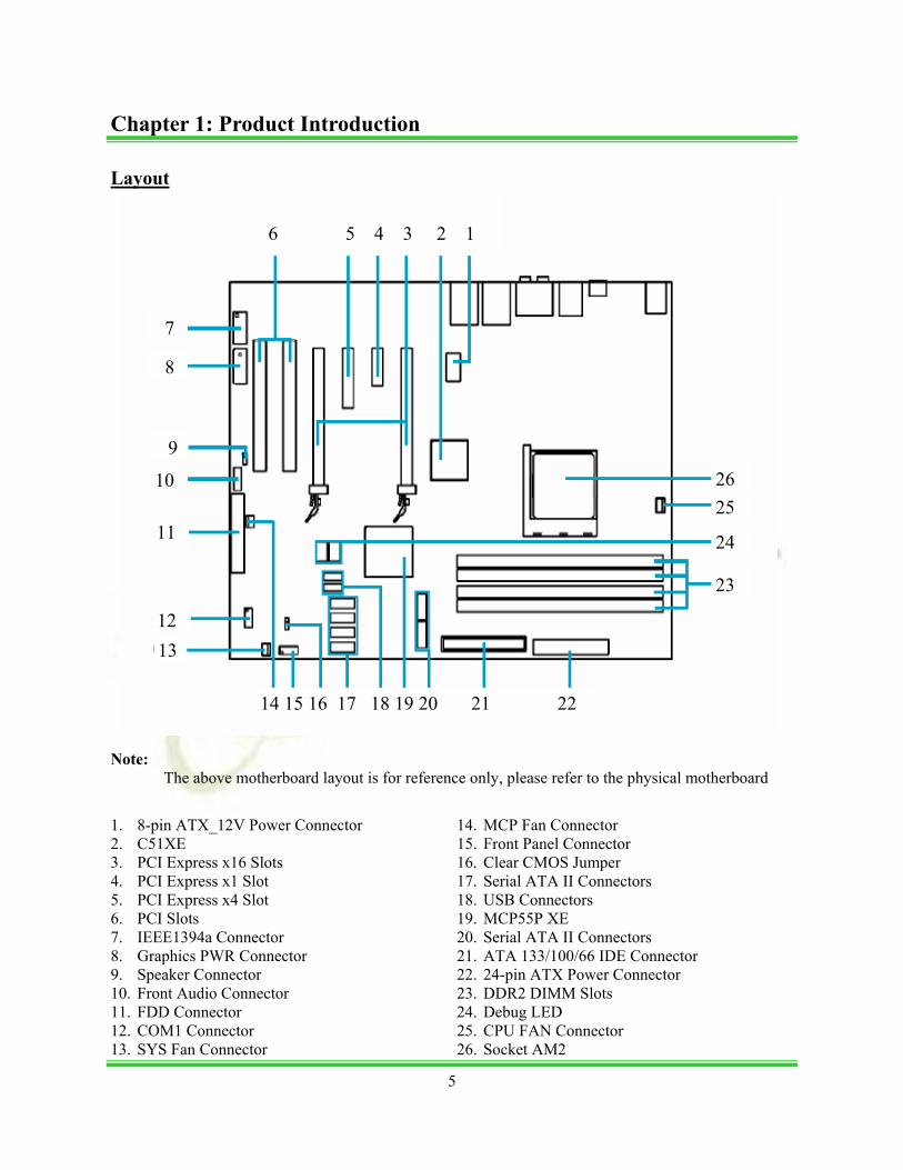
Layout
Note: The above motherboard layout is for reference only, please refer to the physical motherboard
1. 8-pin ATX_12V Power Connector 2. C51XE 3. PCI Express x16 Slots 4. PCI Express x1 Slot 5. PCI Express x4 Slot 6. PCI Slots 7. IEEE1394a Connector 8. Graphics PWR Connector 9. Speaker Connector 10. Front Audio Connector 11. FDD Connector 12. COM1 Connector 13. SYS Fan Connector
14. MCP Fan Connector 15. Front Panel Connector 16. Clear CMOS Jumper 17. Serial ATA II Connectors 18. USB Connectors 19. MCP55P XE 20. Serial ATA II Connectors 21. ATA 133/100/66 IDE Connector 22. 24-pin ATX Power Connector 23. DDR2 DIMM Slots 24. Debug LED 25. CPU FAN Connector 26. Socket AM2
6 5 4 3 2 1
7
8
14 15 16 17 18 19 20 21 22
11
9
10
13
24
23
25 26
12
Chapter 1: Product Introduction
5
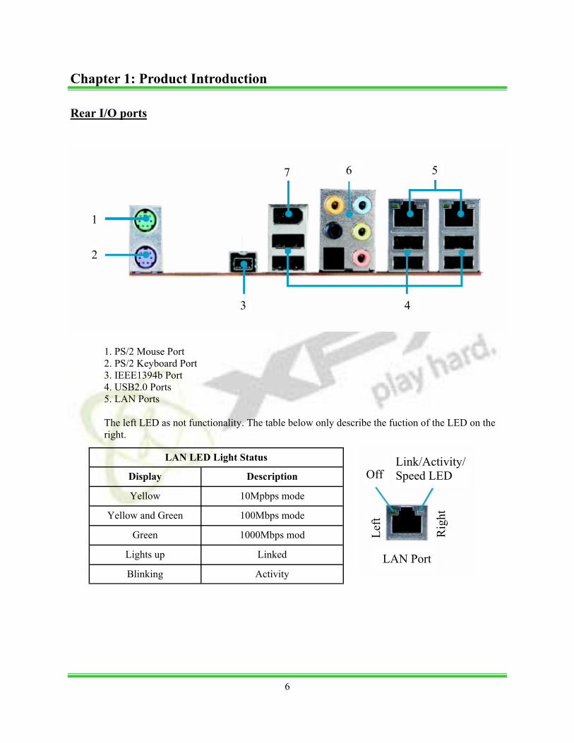
Rear I/O ports
1. PS/2 Mouse Port 2. PS/2 Keyboard Port 3. IEEE1394b Port 4. USB2.0 Ports 5. LAN Ports The left LED as not functionality. The table below only describe the fuction of the LED on the right.
LAN LED Light Status
Display Description
Yellow 10Mpbps mode
Yellow and Green 100Mbps mode
Green 1000Mbps mod
Lights up Linked
Blinking Activity
1
2
5
4 3
7 6
Link/Activity/Speed LED Off
LAN Port
Rig
ht
Left
6
Chapter 1: Product Introduction
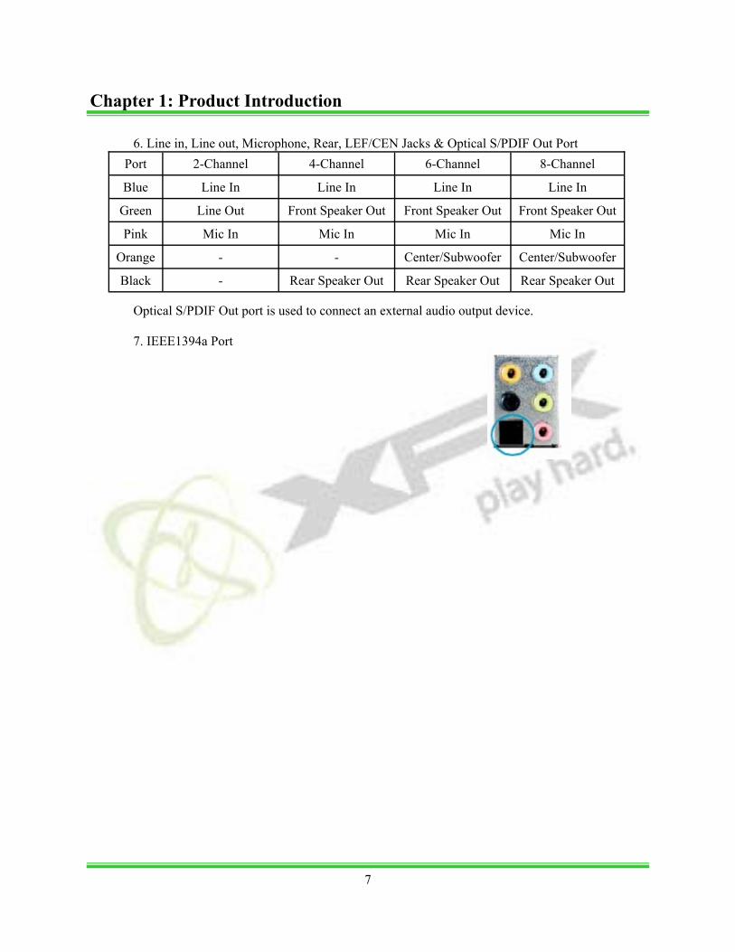
6. Line in, Line out, Microphone, Rear, LEF/CEN Jacks & Optical S/PDIF Out Port
Optical S/PDIF Out port is used to connect an external audio output device. 7. IEEE1394a Port
Port 2-Channel 4-Channel 6-Channel 8-Channel
Blue Line In Line In Line In Line In
Green Line Out Front Speaker Out Front Speaker Out Front Speaker Out
Pink Mic In Mic In Mic In Mic In
Orange - - Center/Subwoofer Center/Subwoofer
Black - Rear Speaker Out Rear Speaker Out Rear Speaker Out
Chapter 1: Product Introduction
7

Chapter 2 Installation Instructions
This chapter introduces the hardware installation process, including the installation of the CPU, mem-ory, power supply, slots, and pin headers, and the mounting of jumpers. Caution should be exercised during the installation of these modules. This chapter includes the following information:
• CPU • Memory • Expansion Slots • Connectors • Power Supply • Jumpers
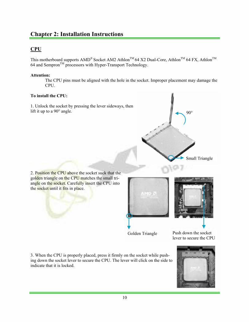
CPU This motherboard supports AMD® Socket AM2 AthlonTM 64 X2 Dual-Core, AthlonTM 64 FX, AthlonTM
64 and SempronTM processors with Hyper-Transport Technology. Attention:
The CPU pins must be aligned with the hole in the socket. Improper placement may damage the CPU.
To install the CPU: 1. Unlock the socket by pressing the lever sideways, then lift it up to a 90° angle. 2. Position the CPU above the socket suck that the golden triangle on the CPU matches the small tri-angle on the socket. Carefully insert the CPU into the socket until it fits in place. 3. When the CPU is properly placed, press it firmly on the socket while push-ing down the socket lever to secure the CPU. The lever will click on the side to indicate that it is locked.
Small Triangle
Golden Triangle
90°
Push down the socket lever to secure the CPU
Chapter 2: Installation Instructions
10
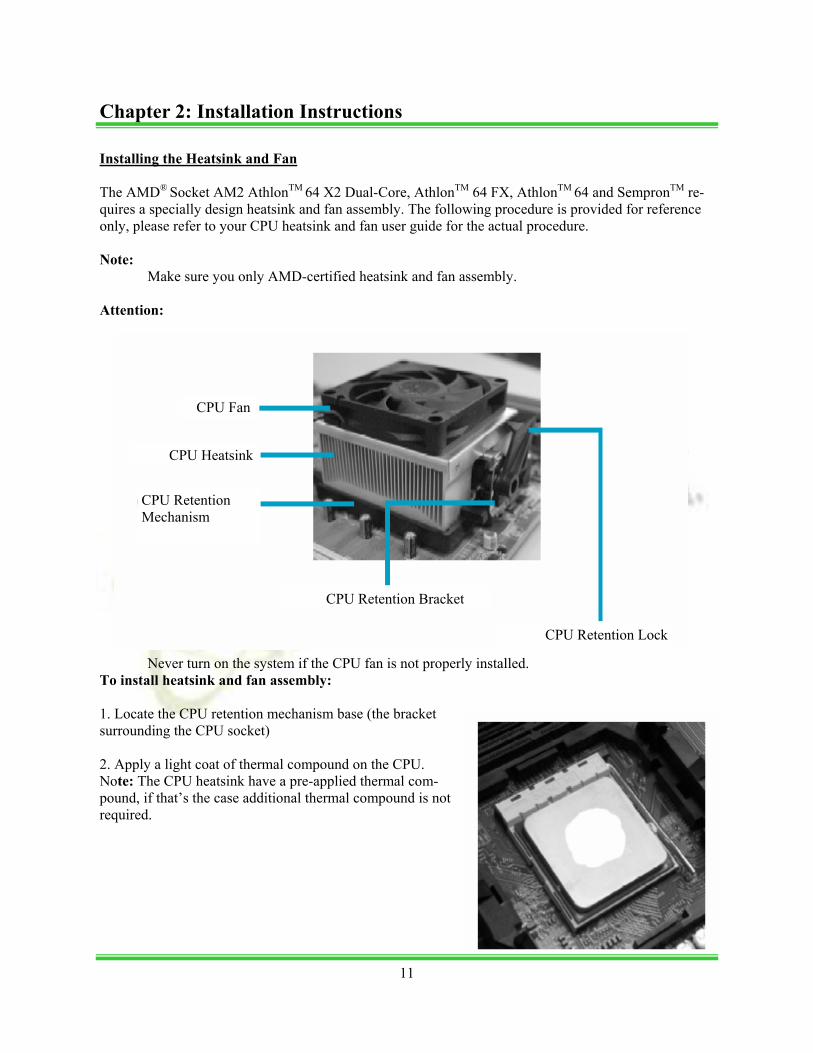
Installing the Heatsink and Fan The AMD® Socket AM2 AthlonTM 64 X2 Dual-Core, AthlonTM 64 FX, AthlonTM 64 and SempronTM re-quires a specially design heatsink and fan assembly. The following procedure is provided for reference only, please refer to your CPU heatsink and fan user guide for the actual procedure. Note: Make sure you only AMD-certified heatsink and fan assembly. Attention:
Never turn on the system if the CPU fan is not properly installed. To install heatsink and fan assembly: 1. Locate the CPU retention mechanism base (the bracket surrounding the CPU socket) 2. Apply a light coat of thermal compound on the CPU. Note: The CPU heatsink have a pre-applied thermal com-pound, if that’s the case additional thermal compound is not required.
CPU Fan
CPU Heatsink
CPU Retention Mechanism
CPU Retention Bracket
CPU Retention Lock
Chapter 2: Installation Instructions
11
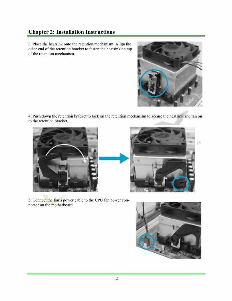
3. Place the heatsink onto the retention mechanism. Align the other end of the retention bracket to fasten the heatsink on top of the retention mechanism. 4. Push down the retention bracket to lock on the retention mechanism to secure the heatsink and fan on to the retention bracket.
5. Connect the fan’s power cable to the CPU fan power con-nector on the motherboard.
Chapter 2: Installation Instructions
12
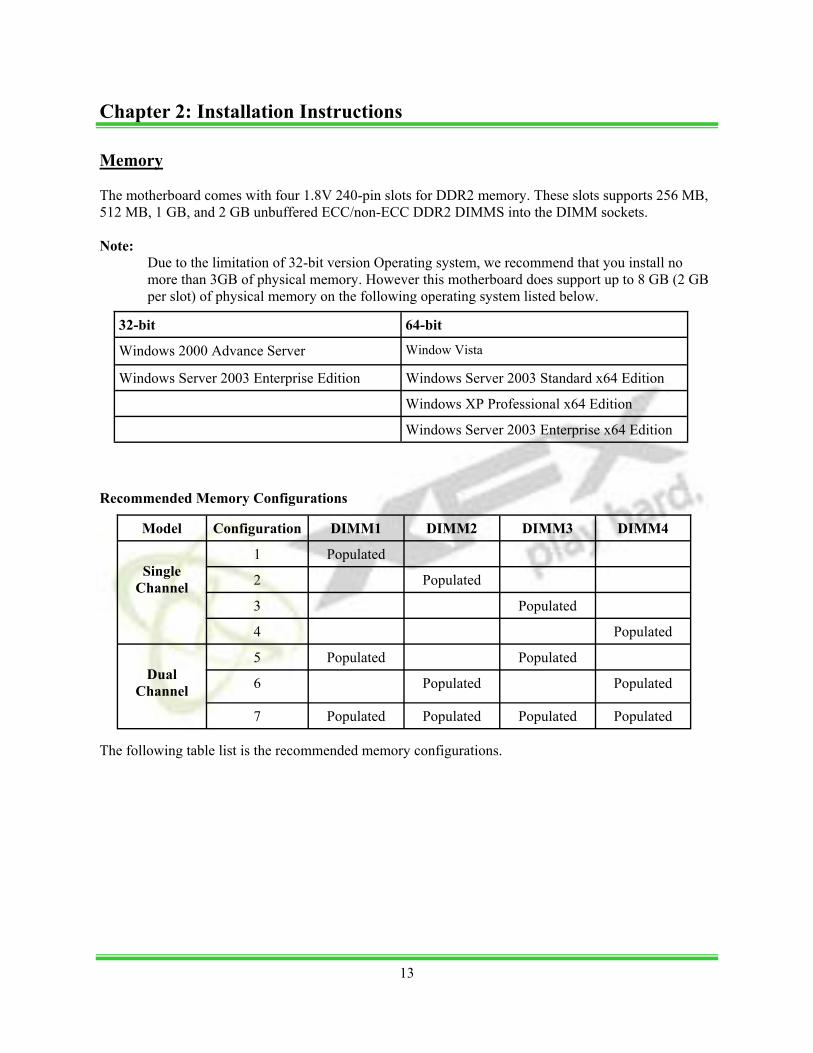
Memory The motherboard comes with four 1.8V 240-pin slots for DDR2 memory. These slots supports 256 MB, 512 MB, 1 GB, and 2 GB unbuffered ECC/non-ECC DDR2 DIMMS into the DIMM sockets. Note:
Due to the limitation of 32-bit version Operating system, we recommend that you install no more than 3GB of physical memory. However this motherboard does support up to 8 GB (2 GB per slot) of physical memory on the following operating system listed below.
Recommended Memory Configurations
The following table list is the recommended memory configurations.
Model Configuration DIMM1 DIMM2 DIMM3 DIMM4
Single
Channel
1 Populated
2 Populated
3 Populated
4 Populated
5 Populated Populated
6 Populated Populated
7 Populated Populated Populated Populated
Dual
Channel
32-bit 64-bit
Windows 2000 Advance Server Window Vista
Windows Server 2003 Enterprise Edition Windows Server 2003 Standard x64 Edition
Windows XP Professional x64 Edition
Windows Server 2003 Enterprise x64 Edition
Chapter 2: Installation Instructions
13
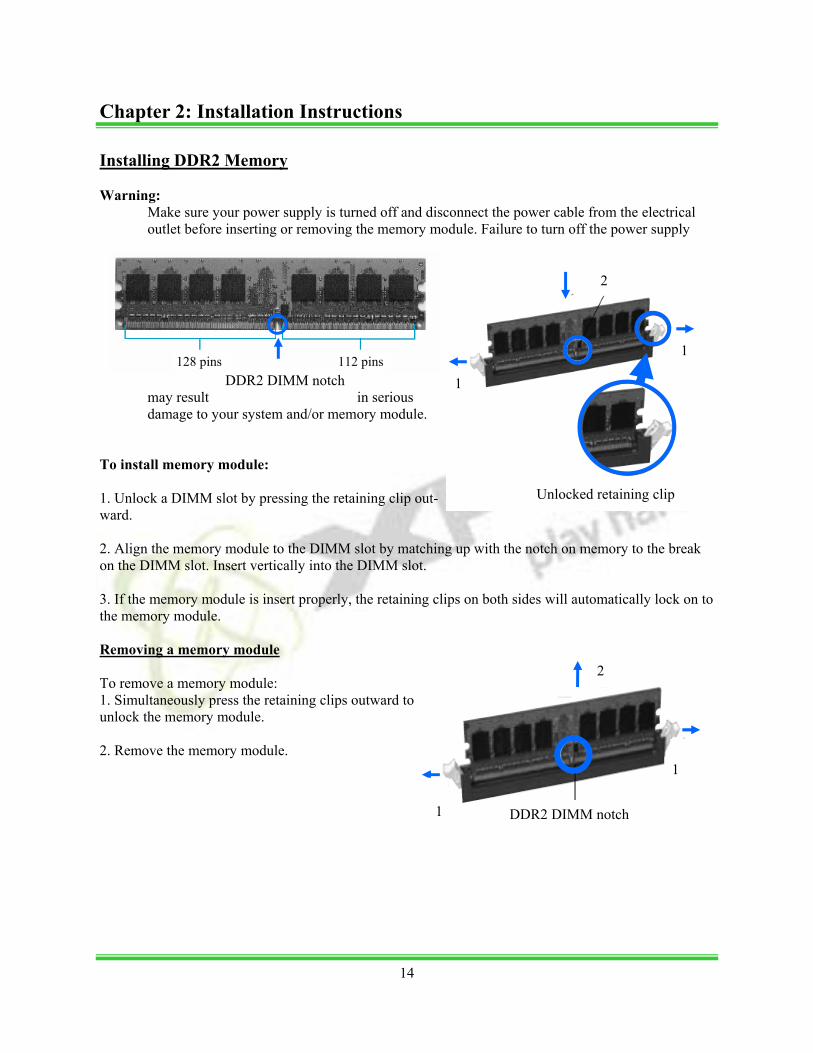
Installing DDR2 Memory Warning:
Make sure your power supply is turned off and disconnect the power cable from the electrical outlet before inserting or removing the memory module. Failure to turn off the power supply
may result in serious damage to your system and/or memory module.
To install memory module: 1. Unlock a DIMM slot by pressing the retaining clip out-ward. 2. Align the memory module to the DIMM slot by matching up with the notch on memory to the break on the DIMM slot. Insert vertically into the DIMM slot. 3. If the memory module is insert properly, the retaining clips on both sides will automatically lock on to the memory module. Removing a memory module To remove a memory module: 1. Simultaneously press the retaining clips outward to unlock the memory module. 2. Remove the memory module.
2
Unlocked retaining clip
1
DDR2 DIMM notch
1
1
1
2
DDR2 DIMM notch
128 pins 112 pins
Chapter 2: Installation Instructions
14

Installing Expansion cards The Motherboard has two 32-bit master PCI bus slots, one PCI Express x1 slot, one PCI Express x4 slot and two PCI Express x16 slots. PCI Slots PCI slots support cards such as LAN card, USB card, Firewire card, SCSI cards and other cards that has a PCI interface. PCI Express x1 and x4 slots PCI Express x1 and x4 slots are designed for less bandwidth-intensive cards, such as modem and LAN cards. PCI Express x16 slots The two PCI Express x16 slots supports NVIDIA’s SLITM (Scalable Link Interface) technology which allows two SLI-ready graphics cards to be installed. Warning:
Make sure your power supply is turned off and disconnect the power cable from the electrical outlet before inserting or removing expansion cards or other peripherals. Failure to turn off the power supply may result in physical injuries and serious damage to your system.
The following procedure is provided for reference only, please refer to the user guide of the product that’s you are installing for the actual procedure. To install expansions cards: 1. Remove that bracket opposite of the slot that you instead to use. If the bracket is fastened with a screw, keep the screw for later use. 2. Align the card connector with the slot and press firmly until the care is completely seated on the slot. 3. Secure the card to the chassis with the screw was removed earlier.
Chapter 2: Installation Instructions
15
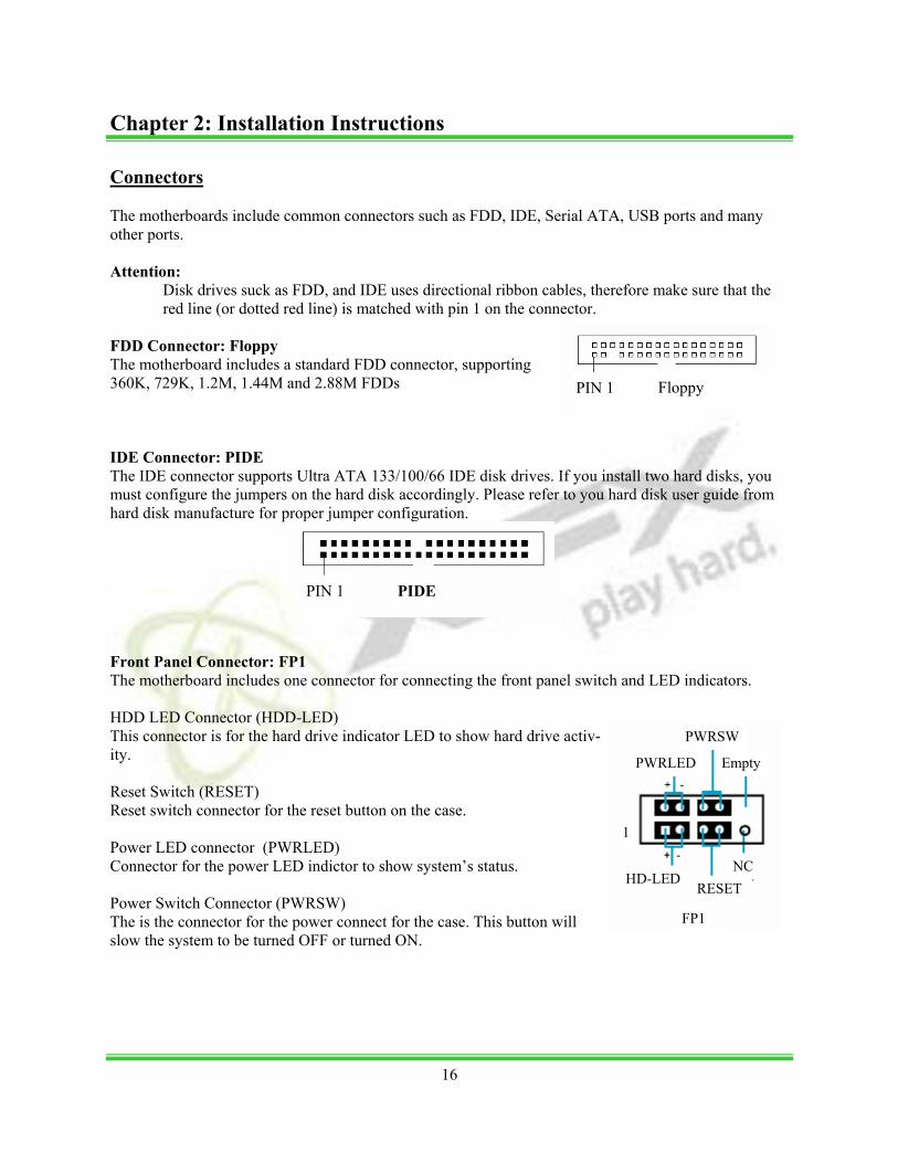
Connectors The motherboards include common connectors such as FDD, IDE, Serial ATA, USB ports and many other ports. Attention:
Disk drives suck as FDD, and IDE uses directional ribbon cables, therefore make sure that the red line (or dotted red line) is matched with pin 1 on the connector.
FDD Connector: Floppy The motherboard includes a standard FDD connector, supporting 360K, 729K, 1.2M, 1.44M and 2.88M FDDs IDE Connector: PIDE The IDE connector supports Ultra ATA 133/100/66 IDE disk drives. If you install two hard disks, you must configure the jumpers on the hard disk accordingly. Please refer to you hard disk user guide from hard disk manufacture for proper jumper configuration. Front Panel Connector: FP1 The motherboard includes one connector for connecting the front panel switch and LED indicators. HDD LED Connector (HDD-LED) This connector is for the hard drive indicator LED to show hard drive activ-ity. Reset Switch (RESET) Reset switch connector for the reset button on the case. Power LED connector (PWRLED) Connector for the power LED indictor to show system’s status. Power Switch Connector (PWRSW) The is the connector for the power connect for the case. This button will slow the system to be turned OFF or turned ON.
Floppy PIN 1
PIN 1 PIDE
PWRLED Empty
PWRSW
1
RESET HD-LED
NC
FP1
16
Chapter 2: Installation Instructions
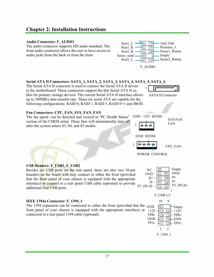
Audio Connector: F_AUDIO The audio connector supports HD audio standard. The front audio connector allows the user to have access to audio jacks from the back or from the front. Serial ATA II Connectors: SATA_1, SATA_2, SATA_3, SATA_4, SATA_5, SATA_6 The Serial ATA II connector is used to connect the Serial ATA II device to the motherboard. These connectors support the thin Serial ATA II ca-bles for primary storage devices. The current Serial ATA II interface allows up to 300MB/s data transfer rate. These six serial ATA are capable for the following configurations: RAID 0, RAID 1, RAID 5, RAID 0+1 and JBOD. Fan Connectors: CPU_FAN, SYS_FAN, FAN The fan speed can be detected and viewed in “PC Health Status” section of the CMOS setup. These fans will automatically turn off after the system enters S3, S4, and S5 modes. USB Headers: F_USB1, F_USB2 Besides six USB ports on the rear panel, there are also two 10-pin hearders on the board with may connect to either the front (provided that the front panel of your chassis is equipped with the appropriate interface) or connect to a rear panel USB cable (optional) to provide additional four USB ports. IEEE 1394a Connector: F_1394_1 The 1394 expansion can be connected to either the front (provided that the front panel of your chassis is equipped with the appropriate interface) or connected to a rear panel 1394 cable (optional).
Port1_L Port1_R Port2_R Sence_send Port2_L
Aud_Gnd Presence_J Sense1_Return Empty Sense2_Return
F_AUDIO
1
SATA II Connector
SYS-FAN FAN
GND +12V SENSE
CPU_FAN
POWER CONTROL
GND SENSE
1
1
Empty GND D+ D- 5V_DUAL
F_USB 1/2
NC GND D+ D- 5V_DUAL
1
F_1394_1
Empty +12V TPB+ GND TPA+
GND +12V TPB- GND TPA-
10 9
1 2
17
Chapter 2: Installation Instructions
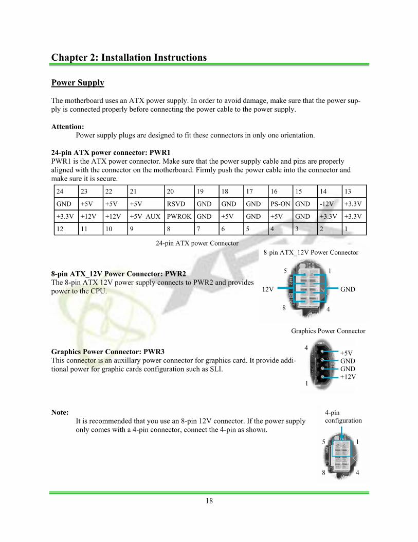
Power Supply The motherboard uses an ATX power supply. In order to avoid damage, make sure that the power sup-ply is connected properly before connecting the power cable to the power supply. Attention:
Power supply plugs are designed to fit these connectors in only one orientation. 24-pin ATX power connector: PWR1 PWR1 is the ATX power connector. Make sure that the power supply cable and pins are properly aligned with the connector on the motherboard. Firmly push the power cable into the connector and make sure it is secure.
8-pin ATX_12V Power Connector: PWR2 The 8-pin ATX 12V power supply connects to PWR2 and provides power to the CPU. Graphics Power Connector: PWR3 This connector is an auxillary power connector for graphics card. It provide addi-tional power for graphic cards configuration such as SLI. Note:
It is recommended that you use an 8-pin 12V connector. If the power supply only comes with a 4-pin connector, connect the 4-pin as shown.
24 23 22 21 20 19 18 17 16 15 14 13
GND +5V +5V +5V RSVD GND GND GND PS-ON GND -12V +3.3V
+3.3V +12V +12V +5V_AUX PWROK GND +5V GND +5V GND +3.3V +3.3V
12 11 10 9 8 7 6 5 4 3 2 1
24-pin ATX power Connector
GND 12V
8-pin ATX_12V Power Connector
5
4 8
1
4
1
+5V GND GND +12V
Graphics Power Connector
4-pin configuration
4 8
1 5
Chapter 2: Installation Instructions
18
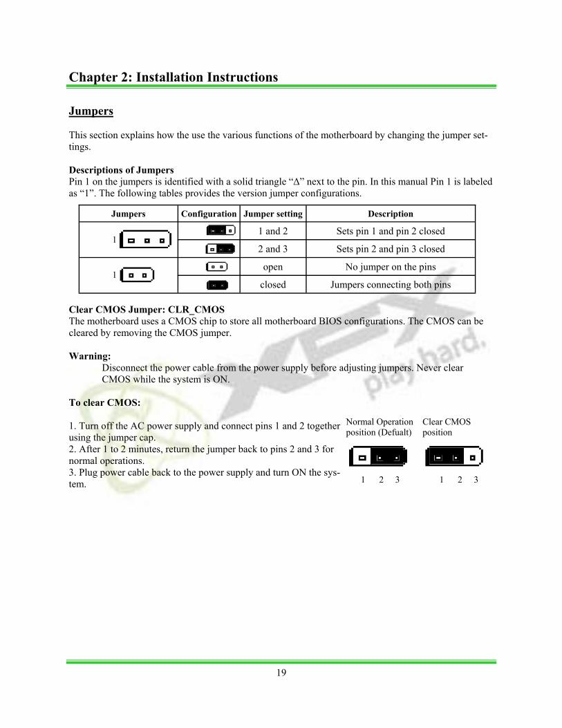
Jumpers This section explains how the use the various functions of the motherboard by changing the jumper set-tings. Descriptions of Jumpers Pin 1 on the jumpers is identified with a solid triangle “∆” next to the pin. In this manual Pin 1 is labeled as “1”. The following tables provides the version jumper configurations.
Clear CMOS Jumper: CLR_CMOS The motherboard uses a CMOS chip to store all motherboard BIOS configurations. The CMOS can be cleared by removing the CMOS jumper. Warning:
Disconnect the power cable from the power supply before adjusting jumpers. Never clear CMOS while the system is ON.
To clear CMOS: 1. Turn off the AC power supply and connect pins 1 and 2 together using the jumper cap. 2. After 1 to 2 minutes, return the jumper back to pins 2 and 3 for normal operations. 3. Plug power cable back to the power supply and turn ON the sys-tem.
Jumpers Configuration Jumper setting Description
1 and 2 Sets pin 1 and pin 2 closed
2 and 3 Sets pin 2 and pin 3 closed
open No jumper on the pins
closed Jumpers connecting both pins
1
1
1 2 3
Normal Operation position (Defualt)
1 2 3
Clear CMOS position
Chapter 2: Installation Instructions
19
Chapter 3 BIOS Setup
This chapter tells how to change system settings through the BIOS Setup menus. Detailed description of the BIOS parameters are also provided. This Chapter includes the following information:
• Enter BIOS setup • Main Menu • Standard CMOS Features • Advance BIOS Features • Advance Chipset Features • Integrated Peripherals • Power Management Setup • PnP/PCI Configurations • System Monitor • Load Defaults • Set Password • Set Username • Save & Exit Setup • Exit Without Saving
Enter BIOS setup The BIOS is the communication bridge between hardware and software. Correctly setting up the BIOS parameters is critical to maintain optimal and stable system performance. To enter the BIOS power the system. When the you see “Press DEL to enter SETUP...” at the bottom of the screen. Press the <DEL> key enter the BIOS. Note:
It is recommended that the default settings in the BIOS are not changed. The user accepts all responsibility for any damage that results from changing the default settings.
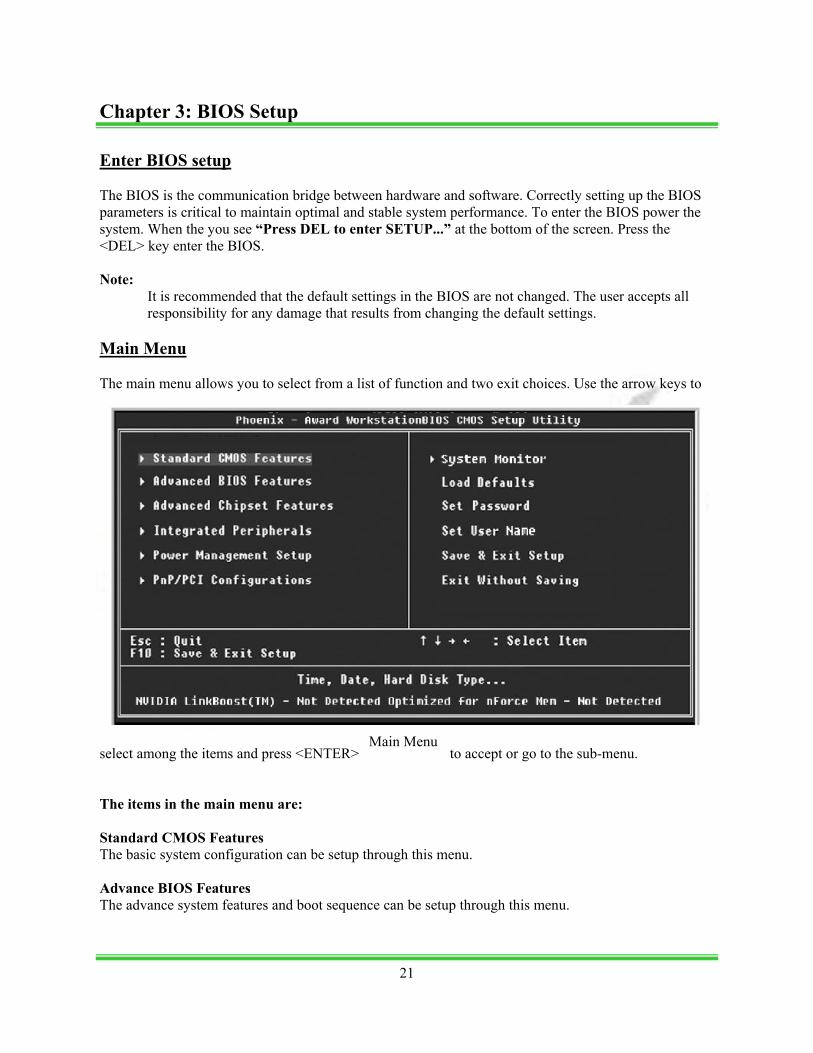
Main Menu The main menu allows you to select from a list of function and two exit choices. Use the arrow keys to
select among the items and press <ENTER> to accept or go to the sub-menu. The items in the main menu are: Standard CMOS Features The basic system configuration can be setup through this menu. Advance BIOS Features The advance system features and boot sequence can be setup through this menu.
Main Menu
Chapter 3: BIOS Setup
21
Advance Chipset Features Optimize system performance through this menu. Configure clocks, voltages, memory timings, and more. Integrated Peripherals Onboard peripherals such as RAID, USB, and MAC control can be setup through this menu. Power Management Setup Configure power management, power-on, and sleep features through this menu. PnP/PCI Configurations The system’s Plug-and-Play and PCI configurations can be modified through this menu. System Monitor Monitor the real-time system status of your PC, including temperature, voltage, and fan speed. Load Defaults Load the NVIDIA LinkBoostTM Technology settings for LinkBoostTM enabled systems. Load default system settings for standard systems. Set Password Set the password to access the BIOS menu. Set User Name Set the BIOS Welcome screen name. Save & Exit Setup Save settings and exit setup. Exit Without Saving Abandon all setting changes and exit setup. NVIDIA LinkBoostTM <STATUS> This status appears at the bottom of the BIOS screen. <STATUS> can be: Detected: System detects an LinkBoost capable components. Not Detected: The LinkBoost components are not detected. SLI-Ready Memory <STATUS> This status appears at the bottom of the BIOS screen. <STATUS> can be: Enabled: SLI-Ready memory detected and enabled. Disabled: SLI-Ready memory detected but disabled. Not Detected: SLI-Ready memory not detected.
22
Chapter 3: BIOS Setup
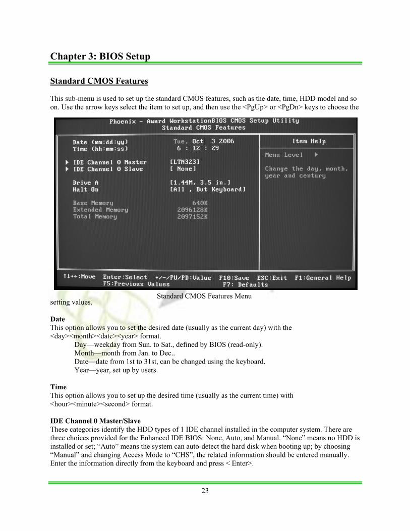
Standard CMOS Features This sub-menu is used to set up the standard CMOS features, such as the date, time, HDD model and so on. Use the arrow keys select the item to set up, and then use the <PgUp> or <PgDn> keys to choose the
setting values. Date This option allows you to set the desired date (usually as the current day) with the <day><month><date><year> format.
Day—weekday from Sun. to Sat., defined by BIOS (read-only). Month—month from Jan. to Dec.. Date—date from 1st to 31st, can be changed using the keyboard. Year—year, set up by users.
Time This option allows you to set up the desired time (usually as the current time) with <hour><minute><second> format. IDE Channel 0 Master/Slave These categories identify the HDD types of 1 IDE channel installed in the computer system. There are three choices provided for the Enhanced IDE BIOS: None, Auto, and Manual. “None” means no HDD is installed or set; “Auto” means the system can auto-detect the hard disk when booting up; by choosing “Manual” and changing Access Mode to “CHS”, the related information should be entered manually. Enter the information directly from the keyboard and press < Enter>.
Standard CMOS Features Menu
23
Chapter 3: BIOS Setup
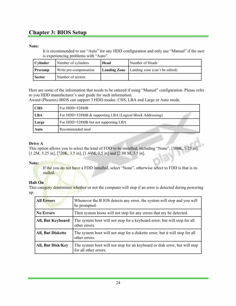
Note:
It is recommended to use “Auto” for any HDD configuration and only use “Manual” if the user is experiencing problems with “Auto”.
Here are some of the information that needs to be entered if using “Manual” configuration. Please refer to you HDD manufacturer’s user guide for such information. Award (Phoenix) BIOS can support 3 HDD modes: CHS, LBA and Large or Auto mode.
Drive A This option allows you to select the kind of FDD to be installed, including “None”, [360K, 5.25 in], [1.2M, 5.25 in], [720K, 3.5 in], [1.44M, 3.5 in] and [2.88 M, 3.5 in]. Note:
If the you do not have a FDD installed, select “None”, otherwise select to FDD is that is in-stalled.
Halt On This category determines whether or not the computer will stop if an error is detected during powering up.
Cylinder Number of cylinders Head Number of Heads
Precomp Write pre-compensation Landing Zone Landing zone (can’t be edited)
Sector Number of sectors
CHS For HDD<528MB
LBA For HDD>528MB & supporting LBA (Logical Block Addressing)
Large For HDD>528MB but not supporting LBA
Auto Recommended mod
All Errors Whenever the B IOS detects any error, the system will stop and you will be prompted.
No Errors Then system boots will not stop for any errors that my be detected.
All, But Keyboard The system boot will not stop for a keyboard error; but will stop for all other errors.
All, But Diskette The system boot will not stop for a diskette error; but it will stop for all other errors.
All, But Disk/Key The system boot will not stop for an keyboard or disk error, but will stop for all other errors.
Chapter 3: BIOS Setup
24
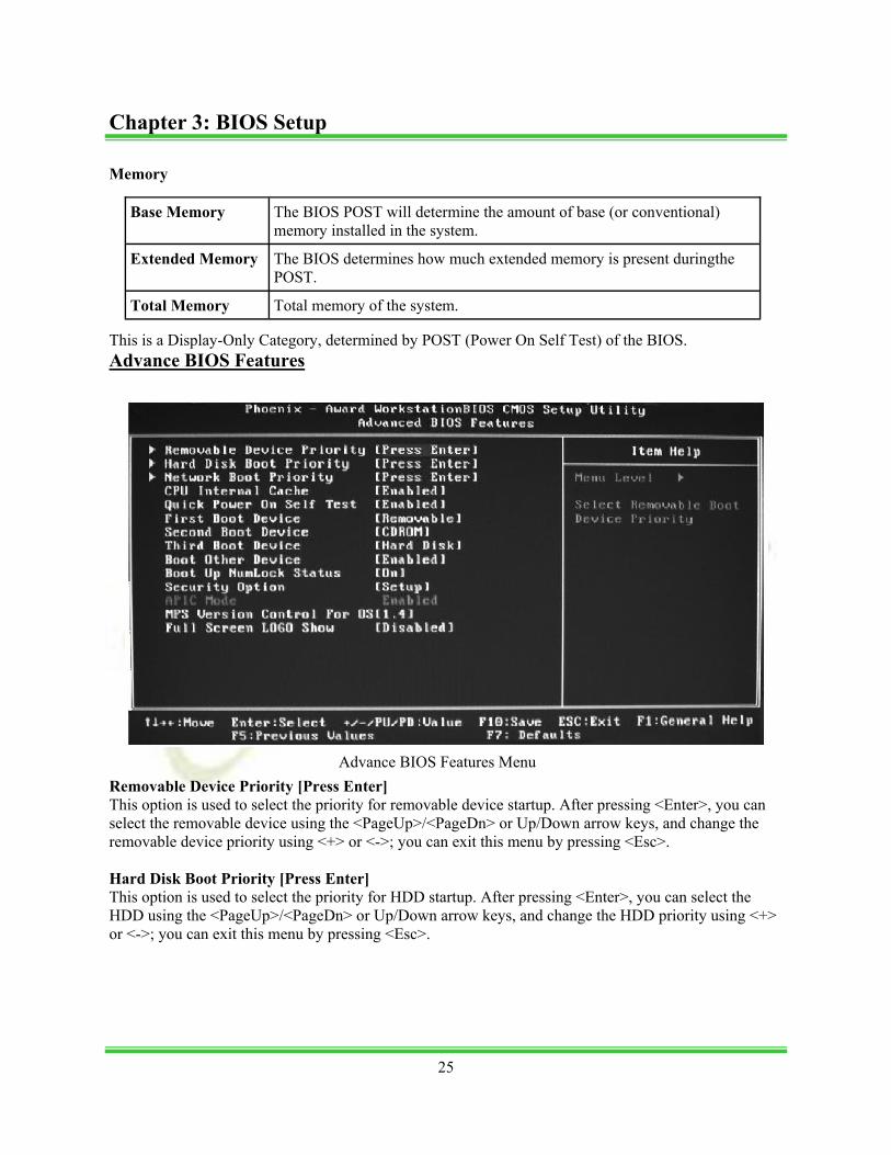
Memory
This is a Display-Only Category, determined by POST (Power On Self Test) of the BIOS. Advance BIOS Features
Removable Device Priority [Press Enter] This option is used to select the priority for removable device startup. After pressing <Enter>, you can select the removable device using the <PageUp>/<PageDn> or Up/Down arrow keys, and change the removable device priority using <+> or <->; you can exit this menu by pressing <Esc>. Hard Disk Boot Priority [Press Enter] This option is used to select the priority for HDD startup. After pressing <Enter>, you can select the HDD using the <PageUp>/<PageDn> or Up/Down arrow keys, and change the HDD priority using <+> or <->; you can exit this menu by pressing <Esc>.
Base Memory The BIOS POST will determine the amount of base (or conventional) memory installed in the system.
Extended Memory The BIOS determines how much extended memory is present duringthe POST.
Total Memory Total memory of the system.
Advance BIOS Features Menu
Chapter 3: BIOS Setup
25

Network Boot Priority [Press Enter] This option is used to select the priority for network startup. After pressing <Enter>, you can select the network using the <PageUp>/<PageDn> or Up/Down arrow keys, and change the network boot priority using <+> or <->; you can exit this menu by pressing <Esc>. CPU Internal Cache [Enable] by Default This option is used to enable or disable the CPU internal cache. Quick Power On Self Test [Enable] by Default Enable to reduce the time for power on self test. First/Second/Third Boot Device [Removable] [CDROM] [Hard Disk] by Defualt This option allows you to set the boot device’s sequence. Boot Other Device [Enable] byby Default With this function set to enable, the system will boot from some other devices if the first/second/third boot devices failed. Boot Up NumLock Status [On] by Default This item defines if the keyboard Num Lock key is active when your system is started. Security Option [Setup] by Default When it is set to “Setup”, a password is required to enter the CMOS Setup screen; When it is set to “System”, a password is required not only to enter CMOS Setup, but also to start up your PC. APIC Mode This option is used to enable or disable APIC function. MPS Version Control For OS [1.4] by Default This option is used to set up the version of MPS Table used in NT4.0 OS. Full Screen LOGO Show [Disable] by Default This option allows you to enable or disable the full-screen logo.
26
Chapter 3: BIOS Setup
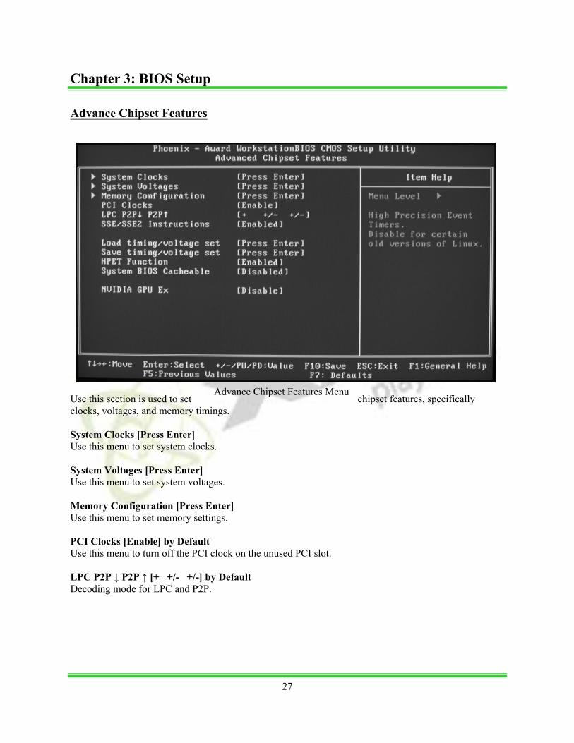
Advance Chipset Features
Use this section is used to set chipset features, specifically clocks, voltages, and memory timings. System Clocks [Press Enter] Use this menu to set system clocks. System Voltages [Press Enter] Use this menu to set system voltages. Memory Configuration [Press Enter] Use this menu to set memory settings. PCI Clocks [Enable] by Default Use this menu to turn off the PCI clock on the unused PCI slot. LPC P2P ↓ P2P ↑ [+ +/- +/-] by Default Decoding mode for LPC and P2P.
Advance Chipset Features Menu
27
Chapter 3: BIOS Setup
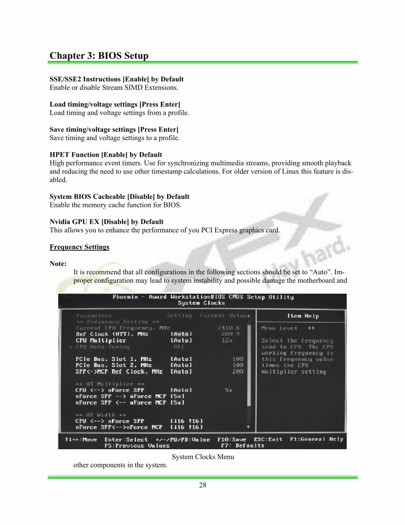
System Clocks Menu
SSE/SSE2 Instructions [Enable] by Default Enable or disable Stream SIMD Extensions. Load timing/voltage settings [Press Enter] Load timing and voltage settings from a profile. Save timing/voltage settings [Press Enter] Save timing and voltage settings to a profile. HPET Function [Enable] by Default High performance event timers. Use for synchronizing multimedia streams, providing smooth playback and reducing the need to use other timestamp calculations. For older version of Linux this feature is dis-abled. System BIOS Cacheable [Disable] by Default Enable the memory cache function for BIOS. Nvidia GPU EX [Disable] by Default This allows you to enhance the performance of you PCI Express graphics card. Frequency Settings Note:
It is recommend that all configurations in the following sections should be set to “Auto”. Im-proper configuration may lead to system instability and possible damage the motherboard and
other components in the system.
28
Chapter 3: BIOS Setup

Ref Clock (HTT) [Auto] by Default Reference clock frequency. CPU Multiplier [Auto] by Default The value of the CPU multiplier. PCIe Bus, Slot 1 [Auto] by Default The frequency of the PCI-Express Bus, Slot 1. PCIe Bus, Slot 2 [Auto] by Default The frequency of the PCI-Express Bus, Slot 2. SPP ← → MCP Ref Clock [Auto] by Default The frequency of the reference clock between SPP and MCP chips. HT Multiplier CPU ← → nForce SPP [Auto] by Default The HT multiplier between the CPU and the SPP. nForce SPP → nForce MCP [5x] by Default The HT multiplier from the SPP to the MCP. nForce SPP ← nForce MCP [5x] by Default The HT multiplier from the MCP to the SPP. HT Width CPU ← → nForce SPP [↓16 ↑16] by Default The HT width between the CPU and the SPP. Force SPP ← → nForce MCP [↓16 ↑16] by Default The HT width between the SPP and the MCP. SATA Spread Spectrum [Enable] by Default Sets the SATA Spread Spetrum option.
29
Chapter 3: BIOS Setup
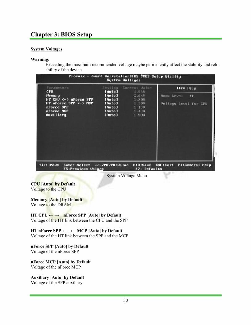
System Voltages Warning:
Exceeding the maximum recommended voltage maybe permanently affect the stability and reli-ability of the device.
CPU [Auto] by Default Voltage to the CPU Memory [Auto] by Default Voltage to the DRAM HT CPU ← → nForce SPP [Auto] by Default Voltage of the HT link between the CPU and the SPP HT nForce SPP ← → MCP [Auto] by Default Voltage of the HT link between the SPP and the MCP nForce SPP [Auto] by Default Voltage of the nForce SPP nForce MCP [Auto] by Default Voltage of the nForce MCP Auxiliary [Auto] by Default Voltage of the SPP auxiliary
System Voltage Menu
30
Chapter 3: BIOS Setup
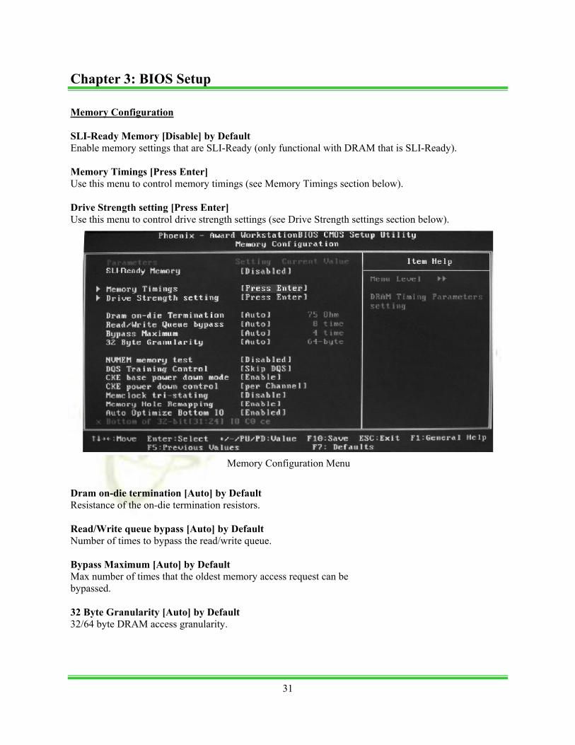
Memory Configuration SLI-Ready Memory [Disable] by Default Enable memory settings that are SLI-Ready (only functional with DRAM that is SLI-Ready). Memory Timings [Press Enter] Use this menu to control memory timings (see Memory Timings section below). Drive Strength setting [Press Enter] Use this menu to control drive strength settings (see Drive Strength settings section below).
Dram on-die termination [Auto] by Default Resistance of the on-die termination resistors. Read/Write queue bypass [Auto] by Default Number of times to bypass the read/write queue. Bypass Maximum [Auto] by Default Max number of times that the oldest memory access request can be bypassed. 32 Byte Granularity [Auto] by Default 32/64 byte DRAM access granularity.
Memory Configuration Menu
31
Chapter 3: BIOS Setup

NVMEM memory test [Diable] by Default Run NVIDIA memory testing module during POST. DQS Training Control [Skip DQS] by Default Perform/Skip DQS training. CKE base power down mode [Enable] by Default Enable or disable CKE base power down mode. CKE power down control [Per Channel] by Default CKE power down mode selection. It should be set to “per channel” for non mobile systems. Memclock tri-stating [Disable] by Default Memclock tri-stating during C3 and Alt VID. Memory Hole remapping [Enable] by Default Enable or disable memory hole remapping. Auto Optimize Bottom IO [Enable] by Default Auto optimize maximum DRAM size when kernel assigns PCI resources done.
32
Chapter 3: BIOS Setup
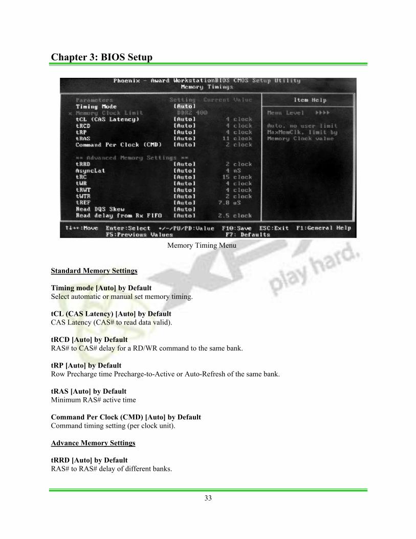
Standard Memory Settings Timing mode [Auto] by Default Select automatic or manual set memory timing. tCL (CAS Latency) [Auto] by Default CAS Latency (CAS# to read data valid). tRCD [Auto] by Default RAS# to CAS# delay for a RD/WR command to the same bank. tRP [Auto] by Default Row Precharge time Precharge-to-Active or Auto-Refresh of the same bank. tRAS [Auto] by Default Minimum RAS# active time Command Per Clock (CMD) [Auto] by Default Command timing setting (per clock unit). Advance Memory Settings tRRD [Auto] by Default RAS# to RAS# delay of different banks.
Memory Timing Menu
33
Chapter 3: BIOS Setup
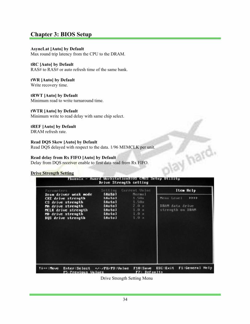
AsyncLat [Auto] by Default Max round trip latency from the CPU to the DRAM. tRC [Auto] by Default RAS# to RAS# or auto refresh time of the same bank. tWR [Auto] by Default Write recovery time. tRWT [Auto] by Default Minimum read to write turnaround time. tWTR [Auto] by Default Minimum write to read delay with same chip select. tREF [Auto] by Default DRAM refresh rate. Read DQS Skew [Auto] by Default Read DQS delayed with respect to the data. 1/96 MEMCLK per unit. Read delay from Rx FIFO [Auto] by Default Delay from DQS receiver enable to first data read from Rx FIFO. Drive Strength Setting
Drive Strength Setting Menu
34
Chapter 3: BIOS Setup
DRAM driver weak mode [Auto] by Default DRAM data drive strength on DRAM. CKE drive strength [Auto] by Default Drive strength of the CKE pins. CS drive strength [Auto] by Default Drive strength of the CS and ODT pins. MA drive strength [Auto] by Default Drive strength of the Address, RAS, CAS, WE, and parity pins. MCLK drive strength [Auto] by Default Drive strength of the MEMCLK pins. MD drive strength [Auto] by Default Drive strength of the Data pins. DQS drive strength [Auto] by Default Drive strength of the DQS pins. Integrated Peripherals
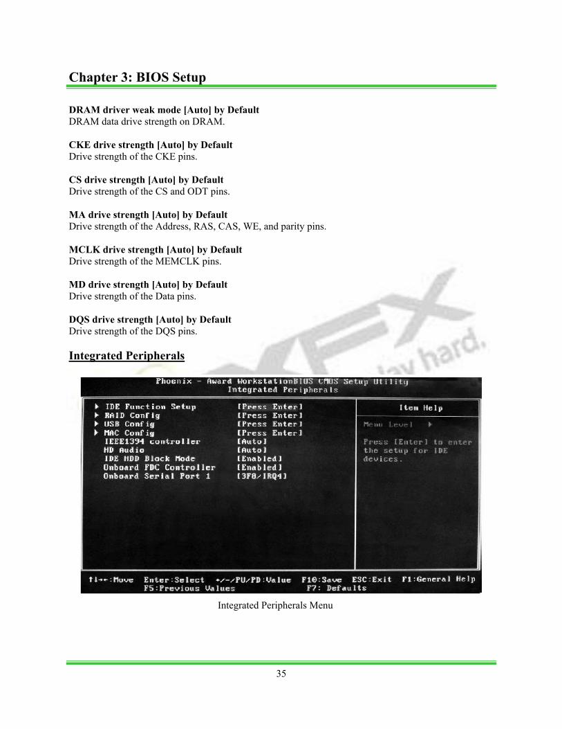
Integrated Peripherals Menu
35
Chapter 3: BIOS Setup
IDE Function Setup [Press Enter] Use this menu to setup the data flow control for IDE. RAID Config [Press Enter] Use this menu to enable or disable SATA RAID. USB Config [Press Enter] Use this menu to setup USB interface. MAC Config [Press Enter] Use this menu to turn off MAC. IEEE 1394 controller [Auto] by Default Use this setting to set whether the IEEE 1394 function is enabled. HD Audio [Auto] by Default Use this setting to configure HD Audio. IDE HDD Block Mode [Enable] by Default Use this setting to configure HDD Block Mode. Onboard FDC Controller [Enable] by Default This option is used to set whether the Onboard FDC Controller is enabled. Onboard Serial Port 1 [3F8/IRQ4] by Default This option is used to assign the I/O address and IRQ for onboard serial port 1.
36
Chapter 3: BIOS Setup
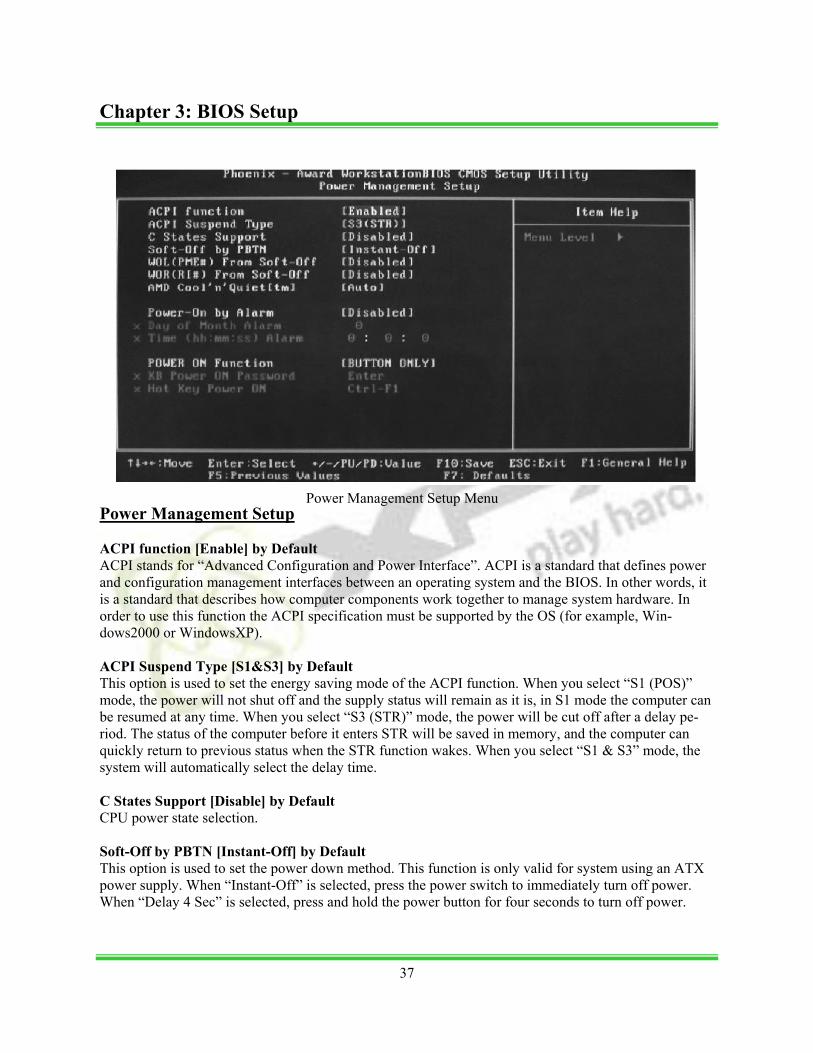
Power Management Setup ACPI function [Enable] by Default ACPI stands for “Advanced Configuration and Power Interface”. ACPI is a standard that defines power and configuration management interfaces between an operating system and the BIOS. In other words, it is a standard that describes how computer components work together to manage system hardware. In order to use this function the ACPI specification must be supported by the OS (for example, Win-dows2000 or WindowsXP). ACPI Suspend Type [S1&S3] by Default This option is used to set the energy saving mode of the ACPI function. When you select “S1 (POS)” mode, the power will not shut off and the supply status will remain as it is, in S1 mode the computer can be resumed at any time. When you select “S3 (STR)” mode, the power will be cut off after a delay pe-riod. The status of the computer before it enters STR will be saved in memory, and the computer can quickly return to previous status when the STR function wakes. When you select “S1 & S3” mode, the system will automatically select the delay time. C States Support [Disable] by Default CPU power state selection. Soft-Off by PBTN [Instant-Off] by Default This option is used to set the power down method. This function is only valid for system using an ATX power supply. When “Instant-Off” is selected, press the power switch to immediately turn off power. When “Delay 4 Sec” is selected, press and hold the power button for four seconds to turn off power.
Power Management Setup Menu
37
Chapter 3: BIOS Setup
WOL(PME#) From Soft-Off [Disable] by Default This item is used to set the system to wake-up on LAN. WOR(RI#) From Soft-Off [Disable] by Default This item is used to set the system to wake-up on ring. AMD Cool ‘n’ Quiet[tm] [Disable] by Default Use this option to enable or disable AMD Cool ‘n’ QuietTM Technology. Power-on by Alarm [Disable] by Default This item is used to set the timing of the power-on function. POWER ON Function [BUTTON ONLY] by Default This option is used to set the power on method for your PC.
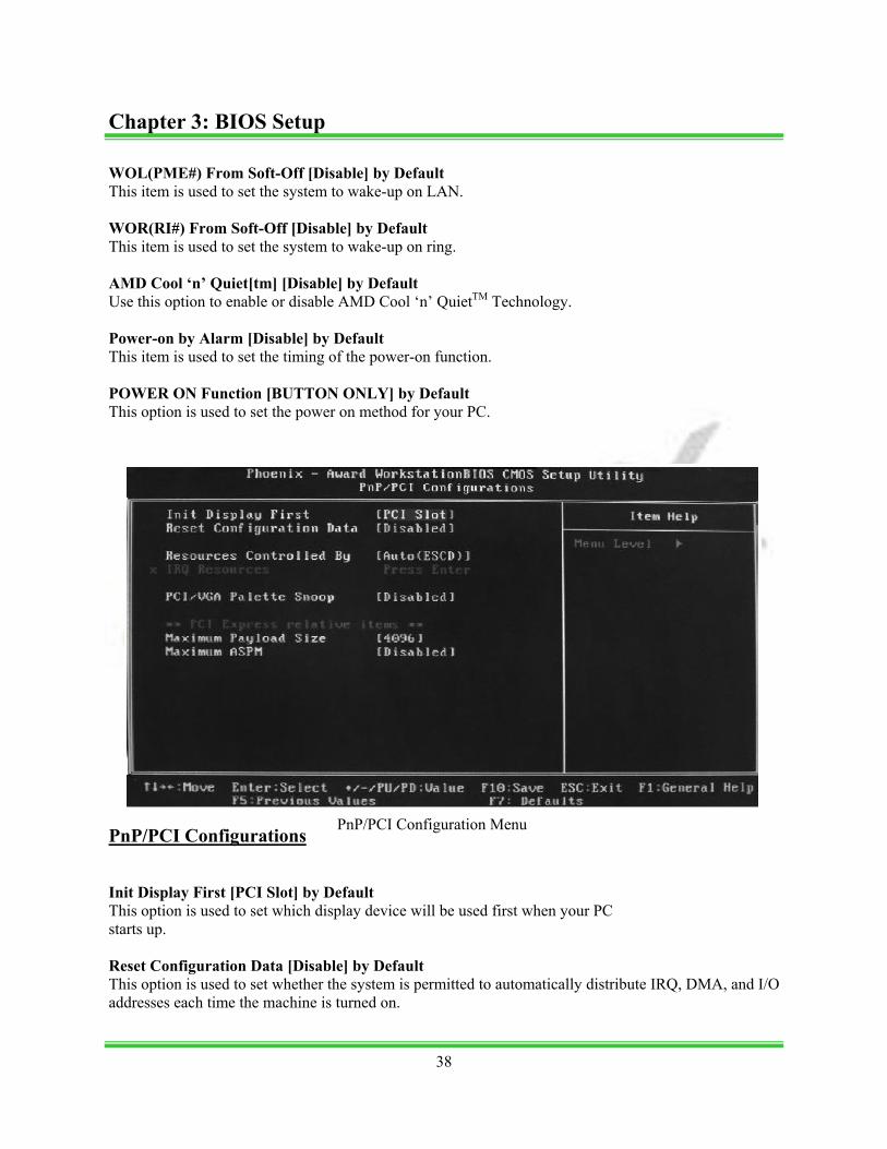
PnP/PCI Configurations Init Display First [PCI Slot] by Default This option is used to set which display device will be used first when your PC starts up. Reset Configuration Data [Disable] by Default This option is used to set whether the system is permitted to automatically distribute IRQ, DMA, and I/O addresses each time the machine is turned on.
PnP/PCI Configuration Menu
38
Chapter 3: BIOS Setup
Resources Controlled by [Auto(ESCD) ] by Default Use this option to determine if IRQ resources are automatically assigned or manually assigned IRQ Resources Press <Enter> to manually assign IRQ resources. PCI/VGA Pallette Snoop [Disable] by Default If you use a non-standard VGA card, use this option to solve graphic acceleration card or MPEG audio card problems (e.g. colors not accurately displayed). Maximum Payload Size [4096] by Default This option is ued to set maximum TLP payload size for PCI Express devices. Maximum ASPM [Disable] by Default Enable/Disable Advance State Power Management System Monitor
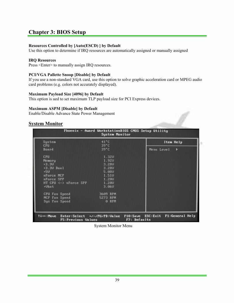
System Monitor Menu
39
Chapter 3: BIOS Setup

Temperature values System The temperature of the system. CPU The temperature of the CPU. Board The temperature of the motherboard. Voltage values CPU The voltage of the CPU. Memory The voltage of the Memory. +3.3V The voltage of the +3.3V . +3.3V Dual The voltage of the +3.3V Dual. +5V The voltage of the +5V. nForce MCP The voltage of the nForce MCP chip. nForce SPP The voltage of the nForce SPP chip. HT CPU <-> nForce SPP The voltage of the HT between the CPU and the nForce SPP chip. +Vbat The voltage of +Vbat. nForce MCP The voltage of the nForce MCP chip. nForce SPP The voltage of the nForce SPP chip.
40
Chapter 3: BIOS Setup

HT CPU <-> nForce SPP The voltage of the HT between the CPU and the nForce SPP chip. +Vbat The voltage of +Vbat. Fan Speed values CPU Fan Speed The CPU fan speed. MCP Fan Speed The MCP fan speed. Sys Fan Speed The system fan speed. Load Defaults The BIOS defaults sets the basic system functions that ensure system stability. If your computer cannot POST properly, you should load the Defaults to restore the original settings. Set Password The password can be used to start the system or modify the CMOS settings. When you select the Set Password option, the following message will appear in the center of the screen:
Enter Password: Enter your password, not exceeding 8 characters, then press <Enter>. The password you enter will re-place any previous password. When prompted, key in the new password and press <Enter>. If you do not want to set a password, just press <Enter> when prompted to enter a password, and in the screen the following message will appear. If no password is keyed in, any user can enter the system and view/modify the CMOS settings.
Password Disabled!!!
Press any key to continue … Set User Name Set the name that will appear on the POST welcome screen.
41
Chapter 3: BIOS Setup
Save & Exit Setup When you select this option and press <Enter>, the following message will appear in the center of the screen:
SAVE to CMOS and EXIT (Y/N)?Y Press <Y> to save your changes in CMOS and exit the program; press <N> or <ESC> to return to the main menu. Exit Without Saving If you select this option and press <Enter>, the following message will appear in the center of the screen:
Quit Without Saving (Y/N)?N Press <Y> to exit CMOS without saving your modifications; press <N> or <ESC> to return to the main menu.
42
Chapter 3: BIOS Setup
Chapter 4 Raid Setup and LED Error Codes
This chapter will introduce the Raid setup process and error codes displayed on the LED. This chapter provides the following information:
• Setting up Raid in the BIOS • Configuring Raid in Nvidia Raid Utility • Installing the Raid Driver (for bootable Raid Array) • On board LED error codes
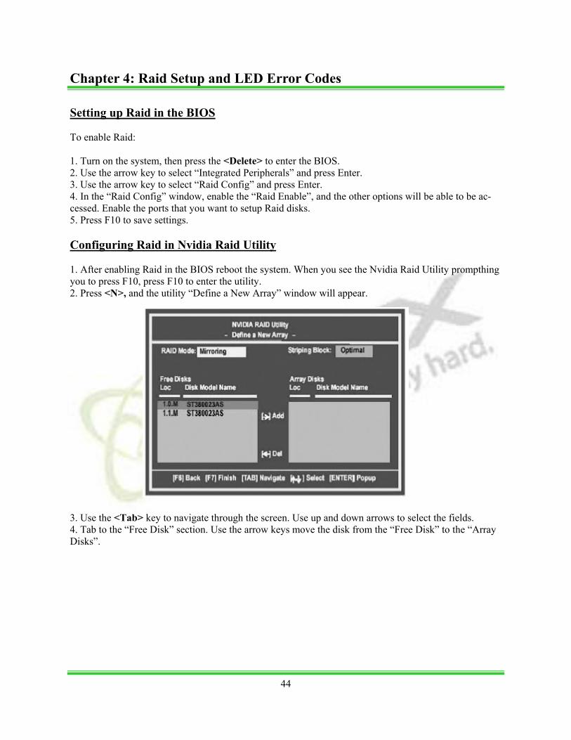
Setting up Raid in the BIOS To enable Raid: 1. Turn on the system, then press the <Delete> to enter the BIOS. 2. Use the arrow key to select “Integrated Peripherals” and press Enter. 3. Use the arrow key to select “Raid Config” and press Enter. 4. In the “Raid Config” window, enable the “Raid Enable”, and the other options will be able to be ac-cessed. Enable the ports that you want to setup Raid disks. 5. Press F10 to save settings. Configuring Raid in Nvidia Raid Utility 1. After enabling Raid in the BIOS reboot the system. When you see the Nvidia Raid Utility prompthing you to press F10, press F10 to enter the utility. 2. Press <N>, and the utility “Define a New Array” window will appear. 3. Use the <Tab> key to navigate through the screen. Use up and down arrows to select the fields. 4. Tab to the “Free Disk” section. Use the arrow keys move the disk from the “Free Disk” to the “Array Disks”.
44
Chapter 4: Raid Setup and LED Error Codes
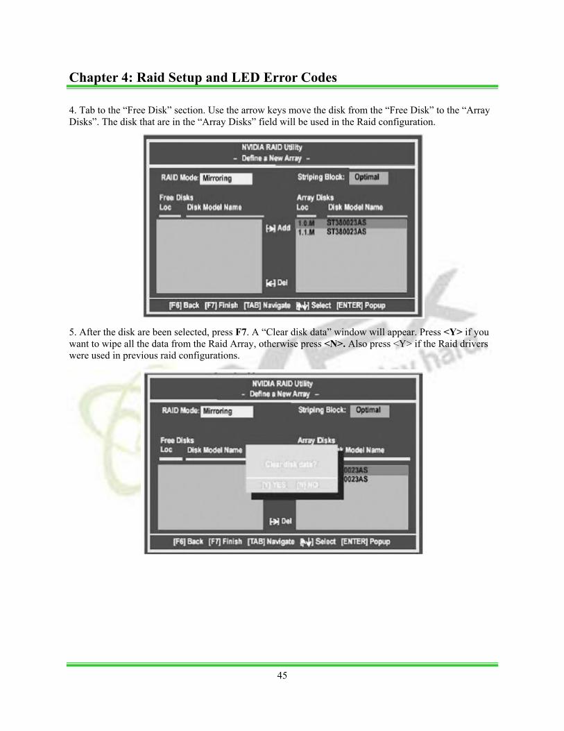
4. Tab to the “Free Disk” section. Use the arrow keys move the disk from the “Free Disk” to the “Array Disks”. The disk that are in the “Array Disks” field will be used in the Raid configuration. 5. After the disk are been selected, press F7. A “Clear disk data” window will appear. Press <Y> if you want to wipe all the data from the Raid Array, otherwise press <N>. Also press <Y> if the Raid drivers were used in previous raid configurations.
45
Chapter 4: Raid Setup and LED Error Codes
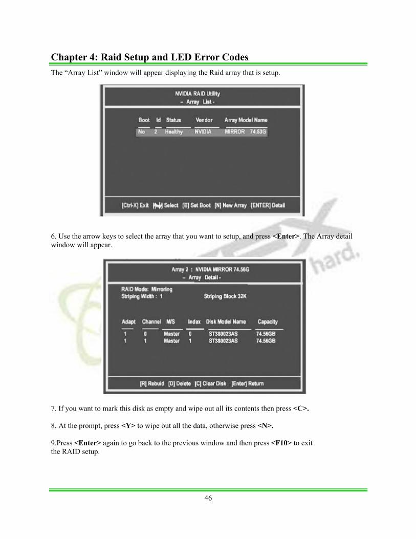
The “Array List” window will appear displaying the Raid array that is setup. 6. Use the arrow keys to select the array that you want to setup, and press <Enter>. The Array detail window will appear. 7. If you want to mark this disk as empty and wipe out all its contents then press <C>. 8. At the prompt, press <Y> to wipe out all the data, otherwise press <N>. 9.Press <Enter> again to go back to the previous window and then press <F10> to exit the RAID setup.
46
Chapter 4: Raid Setup and LED Error Codes

Installing the Raid Driver (for bootable Raid Array) After you complete the RAID BIOS setup, boot from the Windows CD, and the Windows Setup pro-gram starts. 1. Press F6 and wait for the Windows Setup screen to appear. 2. Insert the floppy that has the RAID driver, press <S>. Press <Enter to install “Nvidia Raid Class Ddriver” 3. Press <S> again and select “Nvidia Nforce Storage Controller” and press <Enter>.
47
Chapter 4: Raid Setup and LED Error Codes
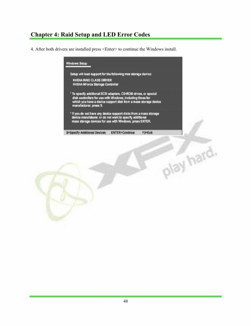
4. After both drivers are installed press <Enter> to continue the Windows install.
48
Chapter 4: Raid Setup and LED Error Codes
On board LED error codes Code(hex) Name Description 01 Reserved 02 Jumps to E000 segment Execution of POST routines in E000 03 Early Superio Init Early Initialized the super IO 04 Reserved 05 Blank video Reset Video controller 06 Reserved 07 Init KBC Keyboard controller init 08 KB test Test the Keyboard 09 Reserved 0A Mouse Init Initialized the mouse 0B Reserved 0C Reserved 0D Reserved 0E Check Sum Check Check the integrity of the ROM, BIOS and message 0F Reserved 10 Autodetect EEPROM Check Flash type and copy flash write/erase routines 11 Reserved 12 Test CMOS Test and Reset CMOS 13 Reserved 14 Load Chipset Load Chipset Defaults 15 Reserved 16 Init Clock Initialize onboard clock generator 17 Reserved 18 Init CPU CPU ID and initialize L1/L2 cache 19 Reserved 1A Reserved 1B Setup Vector Table Interrupt Initialize first 120 interrupt vectors with SPURIOUS_INT_HDLR and initialize INT 00h-1Fh according to INT_TBL 1C CMOS Battery Check Test CMOS and check Battery Fail 1D Early PM Early PM initialization 1E Reserved 1F Re-initial KB Load keyboard matrix 20 Reserved 22 HPM init Init Heuristic Power Management (HPM) 23 Program chipset Early Programming of chipset registers 24 Init PNP Init PNP 25 Shadow VBIO Shadow system/video BIOS 26 Clock Gen Init onboard clock generator and sensor 27 Setup BDA Setup BIOS DATA AREA (BDA) 28 Reserved
49
Chapter 4: Raid Setup and LED Error Codes
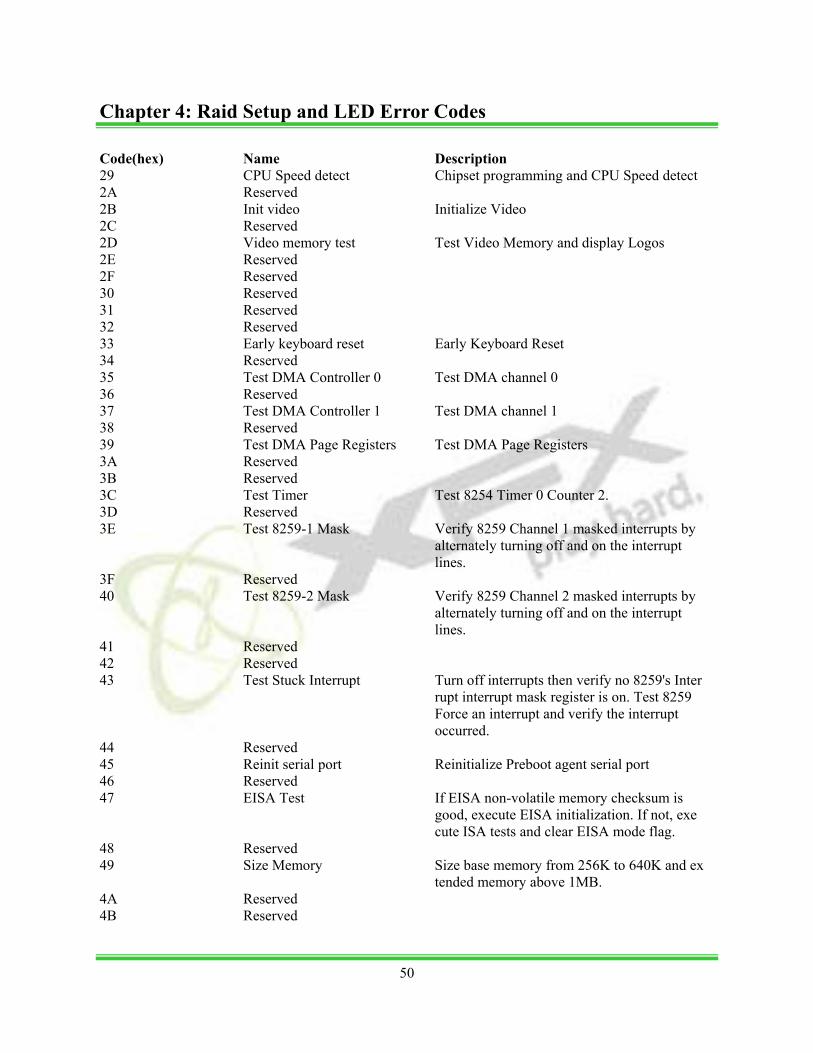
Code(hex) Name Description 29 CPU Speed detect Chipset programming and CPU Speed detect 2A Reserved 2B Init video Initialize Video 2C Reserved 2D Video memory test Test Video Memory and display Logos 2E Reserved 2F Reserved 30 Reserved 31 Reserved 32 Reserved 33 Early keyboard reset Early Keyboard Reset 34 Reserved 35 Test DMA Controller 0 Test DMA channel 0 36 Reserved 37 Test DMA Controller 1 Test DMA channel 1 38 Reserved 39 Test DMA Page Registers Test DMA Page Registers 3A Reserved 3B Reserved 3C Test Timer Test 8254 Timer 0 Counter 2. 3D Reserved 3E Test 8259-1 Mask Verify 8259 Channel 1 masked interrupts by alternately turning off and on the interrupt lines. 3F Reserved 40 Test 8259-2 Mask Verify 8259 Channel 2 masked interrupts by alternately turning off and on the interrupt lines. 41 Reserved 42 Reserved 43 Test Stuck Interrupt Turn off interrupts then verify no 8259's Inter rupt interrupt mask register is on. Test 8259 Force an interrupt and verify the interrupt occurred. 44 Reserved 45 Reinit serial port Reinitialize Preboot agent serial port 46 Reserved 47 EISA Test If EISA non-volatile memory checksum is good, execute EISA initialization. If not, exe cute ISA tests and clear EISA mode flag. 48 Reserved 49 Size Memory Size base memory from 256K to 640K and ex tended memory above 1MB. 4A Reserved 4B Reserved
50
Chapter 4: Raid Setup and LED Error Codes
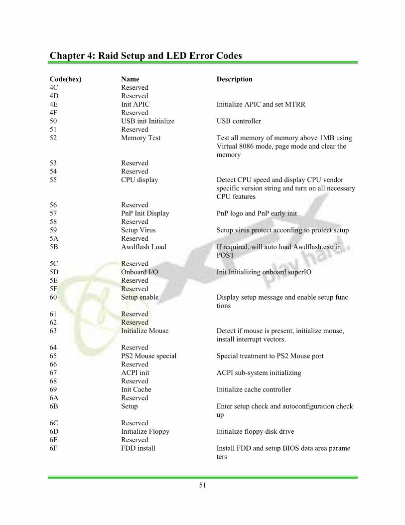
Code(hex) Name Description 4C Reserved 4D Reserved 4E Init APIC Initialize APIC and set MTRR 4F Reserved 50 USB init Initialize USB controller 51 Reserved 52 Memory Test Test all memory of memory above 1MB using Virtual 8086 mode, page mode and clear the memory 53 Reserved 54 Reserved 55 CPU display Detect CPU speed and display CPU vendor specific version string and turn on all necessary CPU features 56 Reserved 57 PnP Init Display PnP logo and PnP early init 58 Reserved 59 Setup Virus Setup virus protect according to protect setup 5A Reserved 5B Awdflash Load If required, will auto load Awdflash.exe in POST 5C Reserved 5D Onboard I/O Init Initializing onboard superIO 5E Reserved 5F Reserved 60 Setup enable Display setup message and enable setup func tions 61 Reserved 62 Reserved 63 Initialize Mouse Detect if mouse is present, initialize mouse, install interrupt vectors. 64 Reserved 65 PS2 Mouse special Special treatment to PS2 Mouse port 66 Reserved 67 ACPI init ACPI sub-system initializing 68 Reserved 69 Init Cache Initialize cache controller 6A Reserved 6B Setup Enter setup check and autoconfiguration check up 6C Reserved 6D Initialize Floppy Initialize floppy disk drive 6E Reserved 6F FDD install Install FDD and setup BIOS data area parame ters
51
Chapter 4: Raid Setup and LED Error Codes
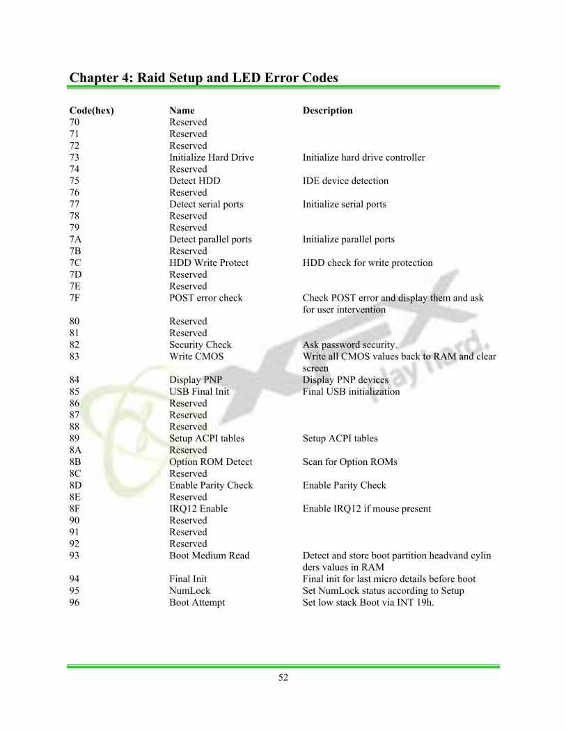
Code(hex) Name Description 70 Reserved 71 Reserved 72 Reserved 73 Initialize Hard Drive Initialize hard drive controller 74 Reserved 75 Detect HDD IDE device detection 76 Reserved 77 Detect serial ports Initialize serial ports 78 Reserved 79 Reserved 7A Detect parallel ports Initialize parallel ports 7B Reserved 7C HDD Write Protect HDD check for write protection 7D Reserved 7E Reserved 7F POST error check Check POST error and display them and ask for user intervention 80 Reserved 81 Reserved 82 Security Check Ask password security. 83 Write CMOS Write all CMOS values back to RAM and clear screen 84 Display PNP Display PNP devices 85 USB Final Init Final USB initialization 86 Reserved 87 Reserved 88 Reserved 89 Setup ACPI tables Setup ACPI tables 8A Reserved 8B Option ROM Detect Scan for Option ROMs 8C Reserved 8D Enable Parity Check Enable Parity Check 8E Reserved 8F IRQ12 Enable Enable IRQ12 if mouse present 90 Reserved 91 Reserved 92 Reserved 93 Boot Medium Read Detect and store boot partition headvand cylin ders values in RAM 94 Final Init Final init for last micro details before boot 95 NumLock Set NumLock status according to Setup 96 Boot Attempt Set low stack Boot via INT 19h.
52
Chapter 4: Raid Setup and LED Error Codes
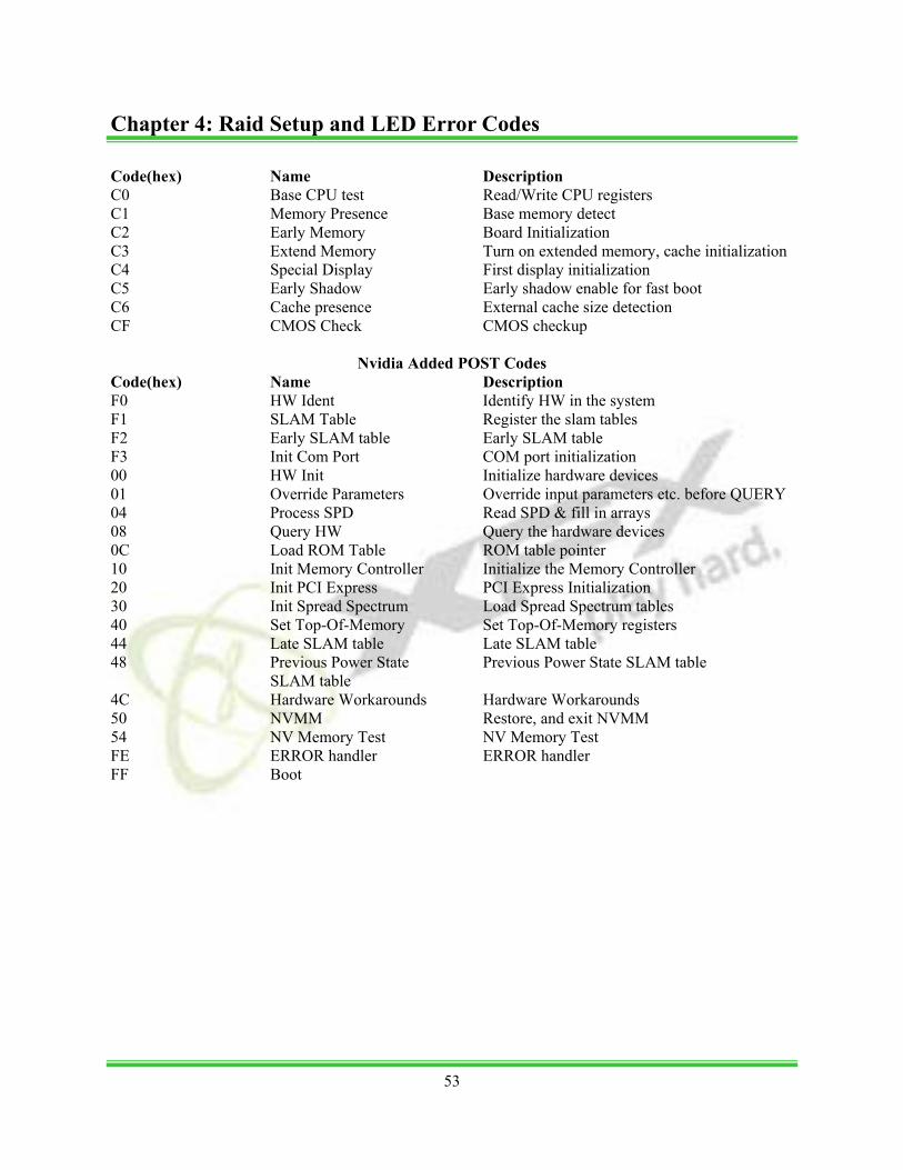
Code(hex) Name Description C0 Base CPU test Read/Write CPU registers C1 Memory Presence Base memory detect C2 Early Memory Board Initialization C3 Extend Memory Turn on extended memory, cache initialization C4 Special Display First display initialization C5 Early Shadow Early shadow enable for fast boot C6 Cache presence External cache size detection CF CMOS Check CMOS checkup
Nvidia Added POST Codes Code(hex) Name Description F0 HW Ident Identify HW in the system F1 SLAM Table Register the slam tables F2 Early SLAM table Early SLAM table F3 Init Com Port COM port initialization 00 HW Init Initialize hardware devices 01 Override Parameters Override input parameters etc. before QUERY 04 Process SPD Read SPD & fill in arrays 08 Query HW Query the hardware devices 0C Load ROM Table ROM table pointer 10 Init Memory Controller Initialize the Memory Controller 20 Init PCI Express PCI Express Initialization 30 Init Spread Spectrum Load Spread Spectrum tables 40 Set Top-Of-Memory Set Top-Of-Memory registers 44 Late SLAM table Late SLAM table 48 Previous Power State Previous Power State SLAM table SLAM table 4C Hardware Workarounds Hardware Workarounds 50 NVMM Restore, and exit NVMM 54 NV Memory Test NV Memory Test FE ERROR handler ERROR handler FF Boot
53
Chapter 4: Raid Setup and LED Error Codes
Trademark
All trademarks are the property of their respective owners.
FCC Compliance Federal Communications Commission Statement This device complies with FCC Rules Part 15. Operation of this device is subject to the following two conditions: • This device may not cause harmful interference. • This device must accept any interference received, including interference that may cause undesired
operation. This equipment has been tested and found to comply with the limits for a Class B digital device, pursu-ant to Part 15 of the FCC Rules. These limits are designed to provide reasonable protection against harmful interference in a residential installation. This equipment generates, uses and can radiate radio frequency energy and, if not installed and used in accordance with the manufacturer’s instructions, may cause harmful interference to radio communications. However, there is no guarantee that interference will not occur in a particular installation. If this equipment does cause harmful interference to radio or television reception, which can be determined by turning the equipment off and on, the user is encour-aged to try to correct the interference by one or more of the following measures: • Reorient or relocate the receiving antenna. • Increase the separation between the equipment and the receiver. • Connect the equipment to an outlet on a circuit different from that to which the receiver is con-
nected. • Consult the dealer or an experienced radio/TV technician for help. Warning: The use of shielded cables for the connection of the monitor to the graphics card is required to assure compliance with FCC regulations. Changes or modifications to this unit not expressly ap-proved by the party responsible for compliance could void the user’s authority to operate this equipment.
CE Compliance This device is in conformity with (reference to the specification under which conformity is declared in accordance with 89/336 EEC-EMC Directive) EN 55022: 1998/A2: 2003 Limits and methods of measurements of radio disturbance characteris- tics of information technology equipment EN 61000-3-2/:2000 Electromagnetic compatibility (EMC) Part 3: Limits Section 2: Limits for harmonic current emissions (equipment input cur- rent <= 16A per phase) EN 61000-3-3/A1:2001 Electromagnetic compatibility (EMC) Part 3: Limits Section 2: Limits of voltage fluctuations and flicker in low-voltage sup- ply systems for equipment with rated current <= 16A EN 55024/A2:2003 Information technology equipment-Immunity characteristics limits and methods of measurement
54
Appendix