Embed Size (px)
Citation preview

XFVHDL4: A Hardware Synthesis Tool for Fuzzy Systems
M. Brox Department of Computer
Architecture University of Cordoba
Cordoba, Spain e-mail: [email protected]
S. Sánchez-Solano Microelectronics Institute of
Seville CNM-CSIC
Seville, Spain e-mail: [email protected]
L. Delgado School of Computer Engineering of
Seville University of Seville
Seville, Spain e-mail: [email protected]
Abstract— This paper presents a design technique that allows the automatic synthesis of fuzzy inference systems and accelerates the exploration of the design space of these systems. It is based on generic VHDL code generation which can be implemented on a programmable device (FPGA) or an application specific integrated circuit (ASIC). The set of CAD tools supporting this technique includes a specific environment for designing fuzzy systems, in combination with commercial VHDL simulation and synthesis tools. As demonstrated by the analyzed design examples, the described development strategy speeds up the stages of description, synthesis, and functional verification of fuzzy inference systems.
Keywords-CAD tools; VHDL code; Fuzzy inference systems; Automatic hardware synthesis
I. INTRODUCTION Fuzzy logic provides an adequate tool to deal with the
uncertainty and imprecision typical of the reasoning system used by the human brain [1]. In particular, the capability of fuzzy control systems to capture the knowledge of human experts and translate it into robust control strategies, describing the behavior of a complex system in a linguistic way by means of IF-THEN rules similar to those employed in natural language, without the need of mathematical models, has motivated a considerable increase in the number of control applications using techniques based on fuzzy inference in the last years [2]-[3].
Different hardware implementation approaches for fuzzy systems by means of ASICs or FPGAs have been proposed in the literature [4]-[5]. Specifically, the recent development of FPGA technologies has led to important advances in programmable logic devices. Current FPGA families have suffered an increase in the number of general purpose resources and specific elements included in this kind of devices, which allow the implementation of a complete system on a programmable chip (SoPC) [6]-[16]. However, the number of design environments and CAD tools able to translate the high-level description of a fuzzy system into an efficient hardware implementation is still small.
This paper proposes a new strategy based on VHDL for the automatic synthesis of fuzzy inference systems. This strategy is integrated into the Xfuzzy environment [17].
Therefore, the proposed design flow combines fuzzy logic design tools provided by Xfuzzy, VHDL commercial synthesis tools, and simulation tools from ModelSim. The first advantage of this strategy is that it allows accelerating the exploration of the design space of fuzzy inference systems. In addition, it allows that the implementation technology may be any of the available in commercial synthesis tools.
The structure of the paper is the following. Section II presents a cell library based on VHDL for efficient implementation of fuzzy inference systems. The automatic synthesis tool, xfvhdl4, based on the previous library, is described in Section III. The design flow and the supporting tools associated to the new methodology are detailed in Section IV. Implementation results for two design examples are illustrated in Section V. The first application example is generated by identification algorithms with the help of a set of numerical data; the second is obtained using a heuristic strategy to solve a problem of autonomous vehicle parking. Finally, Section VI summarizes the main conclusions.
II. VHDL BLOCKS LIBRARY FOR FUZZY SYSTEMS Figure 1 shows the block diagram of an efficient hardware
architecture for fuzzy inference systems which implements a processing strategy that evaluates only the active rules [15]. The first step in order to automate the design process with the proposed architecture is the generation of a library of
Figure 1. Block diagram of an active-rules based architecture for fuzzy systems showing the fuzzification, inference, and defuzzification stages

configurable and synthesizable blocks described in VHDL language. Building a fuzzy system with this library only requires choosing, interconnecting, and assigning values to the parameters of the desired blocks. When the VHDL description of a fuzzy system has been obtained according to the proposed architecture, it is introduced into commercial synthesis tools. The technology where this VHDL description is implemented may be any of the available in these tools, both ASICs and FPGAs.
The first task that has been carried out to build the library is the division of the functionality of the system into blocks. In the fuzzification stage, the membership function circuit (MFC) block used is different depending on the option chosen for implementing the rule antecedents (arithmetic- or memory-based). If the arithmetic option is chosen, the "MFC" block consists of an antecedent memory block for each input of the system, which provides values of point-slope for each membership function. In addition to this memory, an "Arithmetic" block is introduced for each input, whose function is to calculate the membership degrees and labels with the values of point-slope that the antecedent memory provides. With these values of point-slope (ai-pi), and if the condition input ai is true, the following operation is performed to calculate the activation degree:
alpha = (input-ai) · pi (1)
This “Arithmetic-MFC” block generates a family of
membership functions with triangular shapes (except the first and last functions which can be of type "Z" and "S", respectively). In order to control the timing, the block has a clock input and an activation signal (pipeline). With each
rising pipeline edge, existing data in the input bus are internally stored. In a second synchronous process with the clock signal, it is checked if the stored value of input is greater or equal to the point ai. If this condition is true, the activation degree is calculated using equation (1), and this value is stored in an internal register. If the condition is false, the storage is not performed. With the next rising pipeline edge, the value of the stored degree is set in the alpha1 output. Due to the special shape of membership functions, the activation degree of the second active membership function (alpha2) is equal to 1-alpha1, which is achieved in binary by reversing the bits of alpha1. The block also includes the necessary functionality to generate the saturation regions when the membership functions shapes are of type “Z” and “S” for the first and last functions, respectively.
Generated membership functions can be verified using a testbench, also described in VHDL, where a sweep of the input signal is performed. The values of membership degrees and labels are plotted using the facilities from ModelSim simulator. Figure 2 shows a graphical representation, between cursors, for two cases; one of five triangular membership functions and the second one of seven triangular membership functions with saturation in the first and last functions.
When memory storage option is chosen, each "Memory-MFC" block is implemented by a memory block in charge of providing the label and the membership degree.
The inference stage of the architecture includes different blocks. The "Rules Memory" consists of a RAM, ROM, or logical block type memory depending on the implementation option that has been selected. The "Rule Selector" block is a
Figure 2. Graphical representation showing the behavior of an “Arithmetic-MFC” block

multiplexer that is in charge of selecting the active rule. For the "Connective" module, two blocks have been developed depending on the antecedents’ connective used in the knowledge base of the inference system, one that performs the minimum function of its inputs and another that realizes the product operation.
The defuzzification stage has been carried out in two processes, one that is in charge of the accumulation tasks and another that performs the tasks related to the division (if required). For the accumulation process, four blocks that implement different defuzzification methods have been developed: FuzzyMean, WeightedFuzzy Mean, MaxLabel and first-order Takagi-Sugeno [4].
In addition to these blocks that perform the functionality of a fuzzy system, a block in charge of controlling the operation of the rest of blocks has also been developed. For each of the three stages in the architecture shown in Figure 1, a pipeline cycle is required. The minimum number of clock cycles required to perform the tasks associated with the three pipeline stages will be the greatest of: the maximum number of membership functions, the number of active rules, and the number of bits of the output. As an exception, systems that use simplified defuzzification methods require fewer pipeline cycles, since in the last stage only perform the accumulation process but not the division process.
Finally, the library also includes a set of crisp blocks that implement general purpose arithmetic, such as addition, subtraction, multiplication or division functions, and logic operations, as a selector.
Each VHDL description is parameterized by "generic" VHDL statements (generic parameters that are fixed when the component is placed), which facilities the design process
automation that will be described in the following section. VHDL descriptions of these blocks verify the restrictions imposed by the main synthesis tools, so they can be implemented in any technology available for these tools.
III. AUTOMATIC SYNTHESIS OF FUZZY SYSTEMS WITH XFVHDL4
Xfuzzy is a design environment that eases the different stages in the development of a fuzzy inference system. It provides description, simulation, learning, simplification, and synthesis tools that allow defining, verifying, optimizing, and implementing fuzzy systems [18]. A fuzzy inference module is described by means of a specification using the Xfuzzy Specification Language (XFL3), which combines fuzzy blocks (to perform control and decision-making tasks) and crisp blocks (to implement general purpose arithmetic and logic blocks). A new synthesis tool recently incorporated to the environment, xfvhdl4, allows translating a XFL3 specification into a VHDL description that can be implemented on a programmable device (FPGA) or as an application specific integrated circuit (ASIC). The Graphical User Interface (GUI) of this tool is shown in Figure 3.
The middle left area contains the knowledge base, structured as a pull-down menu with components grouped under the categories “RuleBases” and “CrispBlocks”. When a particular rulebase is selected, the middle right area allows defining parameters related to the dimension of the system. This area also shows information about membership functions and rulebases extracted from the XFL3 specification. The user can select the implementation option chosen for the antecedents: arithmetic or memory storage. FPGA design tools usually allow selecting the type of memory used in the implementation stage. For this reason,
Figure 3. Graphical User Interface of xfvdl4

the user can choose the memory type (RAM, ROM or logical block) that will be include in the VHDL description of the “MFC” block for both options. For the “Rules Memory” implementation, the memory type can also be selected.
When all the architectural options have been selected and the parameters related to the buses size have been defined, the fuzzy system components are identified by green marks close to them. Then it is possible to generate the output files by pressing the button “Generate VHDL code”. Basically, it generates a VHDL description of the fuzzy system with a testbench, also described in VHDL, that allows verifying the functionality of the system. The VHDL file is based on the interconnection of the library blocks that have been described in the previous section. At the beginning of this file a package of constants is introduced. These constants are automatically calculated from the values extracted from the knowledge database and the parameters related to the bus sizes that are introduced by the user. When the interconnection of library blocks is performed, the generic parameters of each block are connected to the constants defined in the package.
If the system is hierarchical, a VHDL description is generated for each rulebase in addition to a testbench (for each one of them) that allows checking the control surface
obtained for each knowledge database. A structural VHDL description of the hierarchical system is also obtained, with a testbench that allows verifying the corresponding input-output behavior. The resulting VHDL code is composed by the interconnection of the VHDL descriptions obtained for each rulebase.
The library blocks used for the defuzzification method and the antecedents’ connective are extracted directly from the XFL3 specification. However, other library components and the VHDL description style included in the code depend on the architectural options that the user has selected. Specifically, if the memory type chosen for the antecedents and rules memory is logical block, the description generated is performed by means of a CASE statement and, in the case of FPGA implementation, CLBs of the programmable device are configured as logic blocks. When the selected option is ROM memory, if the user selects the corresponding option, the synthesis tool can extract the ROM memory to implement these descriptions. Finally, if the selected option is RAM memory, CLBs of the programmable device are configured as distributed RAM memory or embedded RAM memory blocks (BRAMs) can also be used for the implementation of antecedents and rules memories without consuming additional resources of the FPGA.
IV. DESIGN FLOW The design methodology shown in this section combines
the use of specific tools for development of fuzzy systems from the Xfuzzy environment, VHDL commercial synthesis tools, and simulation tools from ModelSim. The development of a fuzzy control system will be carried out at the different stages illustrated in Figure 4.
The first stage of the design flow of a fuzzy controller is developed using the tools included in the Xfuzzy design environment. Knowledge rulebases can be directly defined by an expert operator (xfedit) or they can be extracted from numerical data using identification (xfdm). For a better performance, the variable labels as well as the rulebase can be simplified (xfsp). Once the system is identified and simplified, its parameters can be adjusted by supervised learning tools (xfsl). Functional verification is carried out by two tools included in Xuzzy (xplot and xfsim). The first of them allows analyzing the input-output relation of the system and the last one allows simulating its closed-loop behavior in combination with a Java-codified model of the plant. Once validated the XFL3 specification, the xfvhdl4 synthesis tool, presented in this paper, is able to generate the files required to start the second design stage.
In the second design stage, the system is described by a VHDL code that combines different blocks of the XfuzzyLib library. The testbench provided by xfvhdl4 allows performing a functional verification of the VHDL description with the ModelSim simulation environment. Once validated the VHDL code, the classic design flow in commercial synthesis tools can be completed using a programmable device or an integrated circuit as implementation technology. Figure 4. Design flow for the development of fuzzy control
systems combining the Xfuzzy environment and commercial synthesis and simulation tools
V. APPLICATION EXAMPLES The above described design flow has been applied to the
implementation of two fuzzy control systems. The first application example tackles the problem of double integrator, which represents a typical problem in control engineering [19]. This fuzzy system is generated by using the identification tool xfdm (Xfuzzy) with the help of a set of numerical data. Figure 5a shows graphically the description of the controller in Xfuzzy. The system uses two rulebases and a crisp block that performs the arithmetic operation of subtraction.
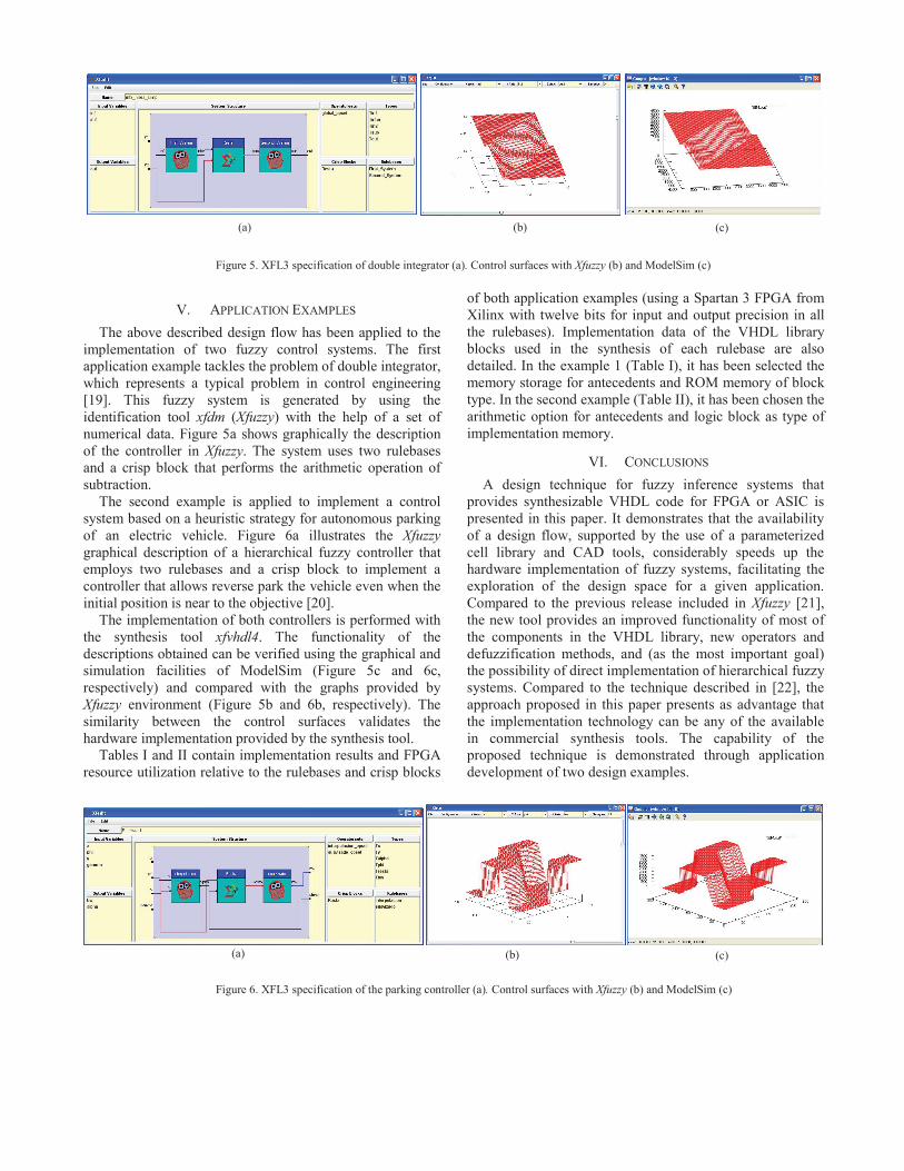
The second example is applied to implement a control system based on a heuristic strategy for autonomous parking of an electric vehicle. Figure 6a illustrates the Xfuzzy graphical description of a hierarchical fuzzy controller that employs two rulebases and a crisp block to implement a controller that allows reverse park the vehicle even when the initial position is near to the objective [20].
The implementation of both controllers is performed with the synthesis tool xfvhdl4. The functionality of the descriptions obtained can be verified using the graphical and simulation facilities of ModelSim (Figure 5c and 6c, respectively) and compared with the graphs provided by Xfuzzy environment (Figure 5b and 6b, respectively). The similarity between the control surfaces validates the hardware implementation provided by the synthesis tool.
Tables I and II contain implementation results and FPGA resource utilization relative to the rulebases and crisp blocks
of both application examples (using a Spartan 3 FPGA from Xilinx with twelve bits for input and output precision in all the rulebases). Implementation data of the VHDL library blocks used in the synthesis of each rulebase are also detailed. In the example 1 (Table I), it has been selected the memory storage for antecedents and ROM memory of block type. In the second example (Table II), it has been chosen the arithmetic option for antecedents and logic block as type of implementation memory.
VI. CONCLUSIONS A design technique for fuzzy inference systems that
provides synthesizable VHDL code for FPGA or ASIC is presented in this paper. It demonstrates that the availability of a design flow, supported by the use of a parameterized cell library and CAD tools, considerably speeds up the hardware implementation of fuzzy systems, facilitating the exploration of the design space for a given application. Compared to the previous release included in Xfuzzy [21], the new tool provides an improved functionality of most of the components in the VHDL library, new operators and defuzzification methods, and (as the most important goal) the possibility of direct implementation of hierarchical fuzzy systems. Compared to the technique described in [22], the approach proposed in this paper presents as advantage that the implementation technology can be any of the available in commercial synthesis tools. The capability of the proposed technique is demonstrated through application development of two design examples.
Figure 5. XFL3 specification of double integrator (a). Control surfaces with Xfuzzy (b) and ModelSim (c)
(a) (b) (c)
Figure 6. XFL3 specification of the parking controller (a). Control surfaces with Xfuzzy (b) and ModelSim (c)
(a) (b) (c)

ACKNOWLEDGMENT This work has been partially supported by European
Community under the MOBY-DIC Project FP7-IST-248858 (www.mobydicproject.eu), by Ministerio de Ciencia e Innovación under the Project TEC2008-04920, and by Junta de Andalucía under the Project P08-TIC-03674 (with support from the PO FEDER-FSE).
REFERENCES
[1] L. A. Zadeh, “Outline of a new approach to the analysis of complex systems and decision processes,” IEEE Trans. Syst., Man, Cybern., vol. SMC-3, no. 1, pp. 28–44, January 1973.
[2] T. J. Ross, Fuzzy Logic With Engineering Applications, 2nd ed. Hoboken, NJ: Wiley, 2004.
[3] J. Jarris, “Fuzzy logic applications in engineering science,” Springer Verlag, 2006.
[4] I. Baturone, A. Barriga, S. Sánchez-Solano, C. J. Jiménez, and D. López, Microelectronic Design of Fuzzy Logic-Based Systems, CRC Press, 2000.
[5] K. Basterretxea, I. del Campo, Electronic hardware for fuzzy computation, in A. Laurent and M-J. Lessot, editors, Scalable Fuzzy Algorithms for Data Management and Analysis: Methods and Design, chapter I, page 27, Information Science Reference, 2009.
[6] E. Monmasson, M. Cirstea, “FPGA Design Methodology for Industrial Control Systems - a Review”, IEEE Transactions on Industrial Electronics, vol.54, No. 4, August 2007.
[7] N. Sulaiman, Z. A. Obaid, M. H. Marhaban, and M. N. Hamidon, “Design and Implementation of FPGA –Based Systems – A Review”, Australian Journal of Basic and Applied Sciences, 3(4): 3575-3596, 2009.
[8] M. McKenna, and B. M. Wilamowshi, “Implementing a fuzzy system on a field programmable gate array”, Proc. Int. Joint Conference on Neural Networks, pp. 189–194, July 2001.
[9] C.-F. Juang, and J.-S Chen, “Water bath temperature control by a recurrent fuzzy controller and its FPGA implementation,” IEEE Trans. on Industrial Electronics, vol. 53, no. 3, pp. 941-949, June 2006.
[10] Y.-S. Kung, C.-C. Huang, and M.-H. Tsai, “FPGA Realization of an Adaptive Fuzzy Controller for PMLSM Drive”, IEEE Trans. on Industrial Electronics, vol. 56, no. 8, pp. 2923-2932, August 2009.
[11] T.-H.S. Li, S.-J. Chang, and Y.-X. Chen, “Implementation of human-like driving skills by autonomous fuzzy behavior control on an FPGA-based car-like mobile robot”, IEEE Trans. on Industrial Electronics, vol. 50, no. 5, pp. 867- 880, October 2003.
[12] S. Islam, Md. Anwarul, Md. Saukat, and M. Othman, “Design and Synthesis of Mobile Robot Controller using Fuzzy”, 28th International Conference on Software Engineering 2006, ICSE 2006, pp. 825-829.
[13] P. Shivkumar, “Intelligent controller for electric vehicle”, IEEE International Conference on Sustainable Energy Technology, ISCET 2008, pp. 978-983.
[14] D. Kim, “An Implementation of fuzzy logic controller on the reconfigurable FPGA system”, IEEE Trans. on Industrial Electronics, vol. 47, no. 3, pp. 703-715, June 2000.
[15] S. Sánchez-Solano, A. Cabrera, I. Baturone, F.J. Moreno-Velo, and M. Brox, “FPGA Implementation of Embedded Fuzzy Controllers for Robotic Applications”, IEEE Trans. on Industrial Electronics, vol. 54, no. 4, pp. 1937-1945, August 2007.
[16] H.-C. Huang, and C.-C. Tsai, “FPGA Implementation of an Embedded Robust Adaptive Controller for Autonomous Omnidirectional Mobile Platform”, IEEE Trans. on Industrial Electronics, vol. 56, no. 5, pp. 1604-1616, May 2009.
[17] ‘Xfuzzy: Fuzzy Logic Design Tools’, IMSE-CNM, CSIC. Available: http://www.imse-cnm.csic.es/Xfuzzy
[18] I. Baturone, F. J. Moreno-Velo, S. Sánchez-Solano, A. Barriga, P. Brox, A. Gersnoviez , M. Brox, “Using Xfuzzy Environment for the Whole Design of Fuzzy Systems”, IEEE International Conference on Fuzzy Systems (FUZZ-IEEE 2007), pp. 517-522, London, July 2007.
[19] I. Baturone, M. C. Martínez-Rodríguez, P. Brox, A. Gersnoviez, and S. Sánchez-Solano, “Digital Implementation of Hierarchical Piecewise-Affine Controllers”, 20th International Symposium on Industrial Electronics (ISIE 2011).
[20] I. Baturone, F. J. Moreno-Velo, S. Sánchez-Solano, and A. Ollero, “Automatic design of fuzzy controllers for car-like autonomous robots”, IEEE Trasactions on Fuzzy Systems, vol. 12, no. 4, pp. 447-465, August 2004.
[21] E. Lago, C. J. Jiménez, D. R. López, S. Sánchez-Solano, A. Barriga. "XFVHDL: A Tool for the Synthesis of Fuzzy Logic Controllers", Proc. Design, Automation and Test in Europe (DATE'98), pp. 102-107, Paris, Feb. 1998
[22] S. Sánchez-Solano, E. del Toro, M. Brox, I. Baturone, and A. Barriga, “A Design Environment for Synthesis of Embedded Fuzzy Controllers on FPGAs”, 2010 IEEE World Congress on Computational Intelligence (WCCI 2010), pp. 44-51, July 2010.
TABLE I IMPLEMENTATION RESULTS (SPARTAN 3A, 12 BITS) USING MEMORY
FOR ANTECEDENTS AND ROM MEMORY OF BLOCK TYPE Module Slices BRAM MULT8X18
Double integrator 8/95 0/14 0/2 +First rulebase 0/40 0/7 0/1 ++Control 7/7 0/0 0/0 ++Antecedent memory 2/2 7/7 0/0 ++Rule selector 8/8 0/0 0/0 ++Rule memory 5/5 0/0 0/0 ++Defuzzifier 18/18 0/0 1/1 +Crisp block 14/14 0/0 0/0 +Second rulebase 0/33 0/7 0/1 ++Control 7/7 0/0 0/0 ++Antecedent memory 1/1 7/7 0/0 ++Rule selector 7/7 0/0 0/0 ++Defuzzifier 18/18 0/0 1/1
TABLE II
IMPLEMENTATION RESULTS (SPARTAN 3A, 12 BITS) USING ARITHMETIC OPTION FOR ANTECEDENTS AND LOGIC BLOCK AS TYPE OF MEMORY
Module Slices BRAM MULT8X18 Backward 21/364 0/0 0/9 +First rulebase 0/233 0/0 0/7 ++Control 6/6 0/0 0/0 ++Antecedent memory 1 7/7 0/0 0/0 ++Antecedent memory 2 6/6 0/0 0/0 ++Arithmetic 1 45/45 0/0 1/1 ++Arithmetic 2 44/44 0/0 1/1 ++Rule selector 1 8/8 0/0 0/0 ++Rule selector 2 7/7 0/0 0/0 ++Rule memory 34/34 0/0 0/0 ++Connective (product) 12/12 0/0 1/1 ++Defuzzifier 64/64 0/0 4/4 +Crisp block 14/14 0/0 0/0 +Second rulebase 0/96 0/0 0/2 ++Control 6/6 0/0 0/0 ++Antecedent memory 14/14 0/0 0/0 ++Arithmetic 48/48 0/0 1/1 ++Rule selector 8/8 0/0 0/0 ++Rule memory 2/2 0/0 0/0 ++Defuzzifier 18/18 0/0 1/1