Embed Size (px)
Citation preview
Mechanics of Advanced Composite Structures 8 (2021) 213 – 234
Semnan University
Mechanics of Advanced Composite
Structures
journal homepage: http://MACS.journals.semnan.ac.ir
* Corresponding author. Tel.: +91-9922868097 E-mail address: [email protected]
DOI: 10.22075/macs.2021.20393.1257 Received 2020-05-12; Received in revised form 2020-09-28; Accepted 2021-04-01 © 2021 Published by Semnan University Press. All rights reserved.
XFEM for Fracture Analysis of Centrally Cracked Laminated Plates Subjected to Biaxial Loads
P. Shailesh a*, A. Lal b a Department of Mechanical Engineering, SRE’s Sanjivani College of Engineering, Affiliated to Savitribai Phule Pune University, Pune,
Kopargaon, 432603, India b Department of Mechanical Engineering, S.V. National Institute of Technology, Surat, 395007, India
K E Y W O R D S
A B S T R A C T
Mixed mode stress intensity
factor
Load factor
Crack growth
Crack propagation
In the present study, fracture response of centrally cracked symmetric angle ply laminated
composite plates subjected to biaxially applied tensile, shear and tensile and shear
combined stresses by implementing well established extended finite element method
(XFEM) are studied. Typical numerical results are presented in terms of mixed mode stress
intensity factors (MSIFs) to examine the effects of, different biaxial load factors, crack
angles, crack lengths, the eccentricity of the crack in X and or Y directions and fiber angle
under the action of different types of biaxial stresses. The effect of loadings on the crack
growth and crack propagation direction and their effects on the MSIFs using global
tracking crack growth algorithm is also presented. The results of the present investigation
will be useful for accurate prediction of fracture response of cracked composite structures,
crack growth and crack propagation behavior which ultimately effects on the structural
safety and integrity of the composite structures.
1. Introduction
In the recent year’s fiber reinforced composites (FRC) are being increasingly used in the aerospace, space craft, marine, automotive, and bio-medical engineering. This is because FRC has several advantages such as mass production, low fabrication cost, good resistance to impact and high ability to meet multi-functional needs (wear, corrosion, thermal resistance and toughness).
During manufacturing and fabrications, due to improper design of the constituent components, imperfection in production and manufacturing procedures and inaccurate measurement of curing parameters these structures are often subjected to different types of internal and external discontinuities in the form of cracks, inclusions, holes, and voids. Since most of these materials exhibit brittle fracture failure with little or no ductility as offered by metals, the behavior of these structures must be understood, and analysis to predict the fracture failure needs to be performed so that the structural safety and
reliability of FRC structures can be increased up to a significant level.
In most of the applications, FRC components are often subjected to complex service loading conditions which may lead to development of cracks in these structures. The complex service loading conditions involved in various sensitive applications of FRC materials are rarely uniaxial, typically involving biaxial or even triaxial states of stress. The presence and growth of cracks in composite structures may lead to the initiation and catastrophic failure of the structures. Hence, accurate predictions of fracture parameters like stress intensity factors (SIFs) and their effect on unstable crack propagation under the action of biaxially acting tensile, shear or even the combination of both these stresses becomes necessary.
Several numerical methods have been suggested in the last decades in order to predict and analyze fracture characteristics in composites. Due to simplicity and stability in handling material heterogeneity, non-linearity and complex boundary condition, the finite element method (FEM) is used extensively as a
Shailesh & Lal / Mechanics of Advanced Composite Structures 8 (2021) 213-234
214
numerical tool in this area. However, the generation of conforming meshes with the evolving discontinuities is an expensive task using conventional FEM. Hence, after several efforts of many researchers, significant improvements in crack modelling using conventional FEM are realized with the development of a partition of unity-based enrichment method.
In earlier days Melenk and Babuska [1] and Duarte and Oden [2] proposed and combined the partition of unity method with the conventional FEM, which was then implemented in actual sense by Mo¨es et al. [3] for modelling and evolving cracks. Further, this method is known as an extended finite element method (XFEM). In XFEM, for modelling the crack, the generalized Heaviside step functions are utilized to account for crack face discontinuity and the two-dimensional linear elastic asymptotic crack-tip displacement functions are used for the crack tip discontinuity.
Several efforts have been made by many researchers in the early days to increase and check the accuracies of XFEM [4-6]. Belytschko et al. [7] and Sukumar et al. [8] described the state of the art for the problems in material science and reviewed the extended, generalized, moving least squares and meshless methods with an emphasis on their applications to various problems in damage mechanics.
To improve the capabilities of XFEM many researchers used and modified this approach to solve more complicated problems [9-13]. For the implementation of the XFEM within the commercial FE code ABAQUS, Giner et al. [14] presented a procedure based on UEL and explained the procedures that interact with ABAQUS. Chatzi et al. [15] proposed improvements in XFEM–GA algorithm by using a weighted average approach. Abdelaziz and Hamouine [16] presented an overview and recent progress of the XFEM in the analysis of crack growth modelling.
For use XFEM to carry out fracture analysis of orthotropic materials, particular treatments and more efficient enrichment functions are required. Hattori et al. [17] proposed the new set of enrichment functions for the crack-tip by means of the Stroh’s formulation for fully anisotropic materials. In this direction, the progressive work has been carried out by Asadpoure et al. [18-19] and Asadpoure and Mohammadi [20], they proposed a small change in crack face and crack tip enrichment functions. Ebrahimi et al. [21] by using meshless based ideas, modified isotropic enrichment functions to enable modelling orthotropic problems. Further to increase the solution accuracy of the XFEM in orthotropic materials, Ghorashi et al. [22] adopted
orthotropic enrichment functions along with sub-triangle technique and described a new approach for modelling discrete cracks in two-dimensional orthotropic media by the element free Galerkin method. Bhardwaj et al. [23] by modelling crack face and crack tip enrichment functions, performed XIGA and simulated the through thickness cracked FGM and composite plates using FSDT under different types of loading and boundary conditions. Chen et al. [24] developed adaptive extended (XIGA) based on LR B-splines and by enhancing signed-distance and orthotropic crack-tip enrichment functions for the simulation of arbitrary holes in orthotropic materials. Further, this approach and enrichment functions are modified by Gu et al. [25-26] and Yu et al. [27] for carrying out simulations of through-cracked Mindlin-Reissner plates and also to perform crack growth in isotropic and orthotropic media. Fang et al. [28] by combining XFEM, developed a new enriched technique based on sign function which can eliminate the blending element problems.
In the last decade, XFEM has become one of the important tools to carry out analysis of structures with discontinuities, various researchers have developed different approaches by utilizing XFEM. Liu et al. [29] developed an accurate extended 3-node triangular plate element in the context of XFEM by integrating the DSG to eliminate shear-locking and presented numerical results of buckling failure analysis of cracked composite functionally graded plates subjected to uniaxial and biaxial compression loads. Wang et al. [30-31] developed a novel local mesh refinement approach and described an adaptive numerical framework for modeling arbitrary inclusions and holes in terms of the XFEM. Yin et al. [32] combined XIGA based on the NURBS and Reissner- Mindlin plate theory, they have evaluated the critical buckling parameters and natural frequencies of defective FGM plates with internal cracks or voids. Ma et al. [33] introduced a novel detection scheme suitable for multiple complex flaw clusters in large structures by adopting XFEM. Yu and Bui [34] described a new adaptive local mesh refinement XFEM approach which combines a posteriori error estimation algorithm, a local non-conformal mesh connection strategy. They have presented some introductory studies of the developed method in two dimensional problems of strong and weak discontinuities. Bui et al. [35] for carrying out the analysis of transient DSIFs of two-dimensional fracture problems of FGMs, introduced and improved the extended moving Kriging based meshfree method by introducing three new different types of correlation function which fully eliminate the user parameter for MK shape functions. Ding et al. [36-37] proposed and
Shailesh & Lal / Mechanics of Advanced Composite Structures 8 (2021) 213-234
215
enhanced a Matlab object-oriented implementation of the variable-node XFEM, an easy-to-use local mesh refinement scheme, they have applied this scheme for modeling strong and weak discontinuities such as cracks, inclusions, voids and for simulations of multiple crack growth in brittle materials.
For carrying out fatigue crack growth analysis, [38-40] proposed and carried out the simulations of three-dimensional fatigue crack growth of 3-D planar, non-planar and arbitrary shape cracks under mechanical and cyclic thermal loads by using XFEM. By applying XFEM, crack interactions have been studied by Pathak [41] in the heterogeneous FGM under mixed mode mechanical and thermal loading environment and Mishra et al. [42] studied the behavior of piezoelectric components in the presence of multiple cracks under thermo-electro-mechanical loading environment. Patil et al. [43] integrated phase field method with multiscale XFEM and simulated the crack growth in highly heterogeneous materials. For 3-D analysis of heterogeneous unit cell, Bansal et al. [44] proposed a multi-split XFEM approach, to reduce the computational cost, a parallel algorithm is developed for large degrees of freedom systems. Kumar et al. [45] proposed a homogenized multigrid XFEM approach for carrying out the crack growth simulations in ductile materials by modelling the geometric and material nonlinearity. They have investigated the load carrying capacity of the structures with microstructural defects.
During fracture toughness tests significant amounts of crack-tip plasticity is exhibited by most of the structural materials, in such situations only biaxially applied stresses are expected to exert a considerable influence on their fracture characteristics along with various biaxial load factors [46-48]. Therefore, there is considerable incentive to perform fracture analysis in which the biaxial stresses along with various biaxial load factors varied over a considerable range of values.
In this direction, earlier work by Liebowitz et al. [49] explained the importance of the second term in the series representation of an exact analytical solution for the crack tip stresses for an infinite center-cracked specimen subjected to symmetric and uniform biaxial loadings. Oladimeji [50] employed the principle of linear superposition by combining the series type analytical solution around the crack tip for studying cracks emanating from a circular hole in a finite sheet under biaxial loading. To simulate crack initiation and propagation, from an initially inclined crack in isotropic and orthotropic material, Theocaris and Papadopoulos [51] proposed a procedure based on either of the two-
term S2-criterion (S2) and the T-criterion (T). Lim et al. [52] suggested to consider the evaluation of singular expression for the stresses and the corresponding displacements near a crack tip and their effect on the predicted crack growth direction in an anisotropic solid subjected to a biaxial loading. [53-54] developed complex variables formulation for the derivation of the complex variable expressions of the elastic field for the orthotropic materials, and studied the elasto-static fracture response of an orthotropic cracked plate. The influence of load biaxiality on the stress intensity factors, crack growth, and on the local stress components in an orthotropic and isotropic medium have been studied by [55-58]. Meek and Ainsworth [59] performed upper and lower bound limit load analyses and finite element analyses of a center-cracked plate under a wide range of biaxial loadings for a wide range of crack sizes and plate lengths.
It is evident from the literature, the various numerical and experimental results indicate that biaxial loadings have shown considerable influence on fracture resistance, crack driving force and load carrying capacity. Considering the heterogeneous nature of composite materials, strengths obtained using uniaxial testing procedures for these materials often does not give the true insights about multi-axially loaded conditions. This puts significant limitations for wide scale, efficient usage of composites in various sensitive engineering structures.
To the author’s knowledge, in contrast to the isotropic materials, lesser attention has been paid to the study of effects of the multi-axial loads in cracked composite structures. Additionally, the ability to successfully model and simulate the multi-axial behavior of composite laminates largely depends on proper choice of numerical algorithm/approach that eventually ensures wide applicability of the respective fracture failure model in describing the corresponding material behavior under variety of complex loading conditions and for different crack configurations and their propagation.
This paper therefore presents a systematic study of the effects of biaxially applied loadings (tensile, shear and tensile and shear combined) on the MSIFs of an inclined through thickness cracked finite angle ply laminated composite plates along with crack propagation path analysis by implementing the well-established, simple and accurate XFEM algorithm. The MSIFs for different biaxial load factors, crack angles, lamination angles, location of the crack along the X and or Y axis by varying crack length to plate width ratio are evaluated. In addition, the detailed investigation of the crack propagation path analysis by applying global tracking crack growth algorithm is carried out in the framework
Shailesh & Lal / Mechanics of Advanced Composite Structures 8 (2021) 213-234
216
of XFEM. The effect of different types of biaxial stresses on the MSIFs with each step of the crack growth and its effect on the crack propagation direction are investigated.
An excellent agreement of the present results with the literature will be helpful for actual manufacturing and determining the fracture behavior of these materials.
2. FEM Formulation for Fracture Analysis of Composite Structures
To evaluate the MSIFs, essential XFEM formulation for fracture analysis of composite materials developed by Mohammadi [60, 61], applied and explained by Asadpoure et al. [18], Asadpoure and Mohammadi [20] is used in the present analysis.
In XFEM, to model the crack problems a numerical model is generated by dividing the model into two parts; first generate a mesh for the total domain geometry (neglecting the existence of any discontinuities/cracks) by the classical finite element method. Then in the second part by considering the location of discontinuities/ cracks and by using appropriate functions, enrichment of the selected nodes near to the discontinuities/ cracks is carried out by adding a few degrees of freedom to the classical finite element. Then, by defining a transition zone between enriched and non-enriched domains the compatibility is achieved. Thus, the total geometry is divided into three sub domains: the standard FEM domain, elements cut by the crack face are enriched by the crack face enrichment functions and the elements cut by crack tip are enriched by crack tip enrichment functions.
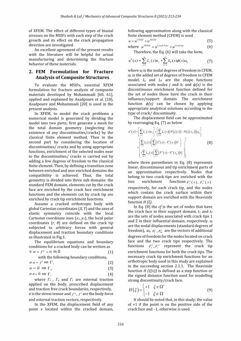
Assume a cracked orthotropic body with global Cartesian coordinates (X, Y) and the axes of elastic symmetry coincide with the local Cartesian coordinate axes (x1, y1), the local polar coordinates (r, θ) are defined on the crack tip subjected to arbitrary forces with general displacement and traction boundary conditions as illustrated in Fig.1.
The equilibrium equations and boundary conditions for a cracked body can be written as
0qf + = in Ω (1)
with the following boundary conditions, tn f = on
t (2)
u u= on u (3)
0n = on c (4)
where Γt , Γu and Γc are external traction applied on the body, prescribed displacement and traction free crack boundaries, respectively, σ is the stress tensor and qf , tf are the body force
and external traction vectors, respectively. In the XFEM, the displacement field of any
point x located within the cracked domain,
following approximation along with the classical finite element method (CFEM) is used
CFEM XFEMu u u= + (5)
where XFEM Crack Face Crack tipu u u= + (6)
Therefore, the Eq. (6) will take the form,
1 1
( ) ( ) ( ) ( )n cr
h
j j k k
j k
u x L x u L x x a= =
= + (7)
where uj is the nodal degrees of freedom in CFEM, ak is the added set of degrees of freedom to CFEM model, Lj and Lk are the shape functions associated with nodes j and k; and ϕ(x) is the discontinuous enrichment function defined for the set of nodes those have the crack in their influence/support domain. The enrichment function ϕ(x) can be chosen by applying appropriate analytical solutions according to the type of crack/ discontinuity.
The displacement field can be approximated by rearranging Eq. (7) as below
( ) ( ) ( ) ( )( ) ( )( )( )
( ) ( ) ( )( )
( ) ( ) ( )( )
1 1
1
2 2
2
1 1
1 1
1 1
2 2
1 1
cfnh
j j k k k
j k
t t ft
l t t l l
l t
t t ft
m t t m m
m t
u x L x u L x H x H x a
L x F x F x b
L x F x F x b
= =
= =
= =
= + −
−
+
+ −
(8)
where three parentheses in Eq. (8) represents linear, discontinuous and tip enrichment parts of an approximation respectively. Nodes that belong to two crack-tips are enriched with the two enrichment functions ( ) ( )1 2,t tF x F x
respectively, for each crack tip, and the nodes which contain the crack surface within their support domain are enriched with the Heaviside function H (ξ).
In Eq. (8) the cf is the set of nodes that have the crack face in their support domain. t1 and t2 are the sets of nodes associated with crack tips 1 and 2 in their influential domain, respectively. uj are the nodal displacements (standard degrees of freedom), ak, 1 2,t t
l mb b are the vectors of additional
degrees of freedom for the nodes located on crack face and the two crack tips respectively. The functions 1 2,t tF F represent the crack tip
enrichment functions for both the crack tips. The necessary crack tip enrichment functions for an orthotropic body used in this study are explained in the succeeding section 2.1.1. The Heaviside function H (ξ(x)) is defined as a step function or the signed distance function used for modelling strong discontinuity/crack face.
( )1
1H
+
−
+ =
− (9)
It should be noted that, in this study; the value of +1 if the point is on the positive side of the crack face and –1, otherwise is used.
Shailesh & Lal / Mechanics of Advanced Composite Structures 8 (2021) 213-234
217
Fig.1. An arbitrary orthotropic body with crack, having
global Cartesian coordinates (X, Y), local polar co-ordinate (r, θ) defined at the crack-tip surrounded by contour ᴦ and its
interior area A with arbitrary boundary conditions subjected to traction f t
2.1. General Displacement, Stress Field and Enrichment Functions for an Orthotropic Cracked Body
The general form of Hooke’s law for the stress- strain relationship of an orthotropic body can be defined as
i ij iC = (i, j = 1,2,6) (10)
where Cij (i, j =1, 2, 6) are the relevant compliance coefficients of the orthotropic material along the local Cartesian coordinate axes (x1, y1) as shown in Fig. 1. Using the basic theories of elasticity and applying the stress function, the governing fourth-order partial differential characteristic equation of an anisotropic body by applying equilibrium and compatibility conditions can be given as
4 3 2
11 16 12 66 26 222 (2 ) 2 0C C C C C C − + + − + = (11)
It can be shown that the roots of Eq. (11) are in the complex form, these roots always occur in conjugate pairs as
1 1, and2 2, having the
general form and are derived as [62]. For numerical purposes, only those roots that have either positive imaginary coefficient or negative one is selected.
The roots μk of Eq. (12) are purely imaginary, which can be given as , with 1,2k ki k = = , [63]
2 2
1,2 12 66 12 66 11 22
11
1(2 ) (2 ) 4
2c c c c c c
c = − − + + − (12)
1 1, where ( 1,2)k kx kyi k = + = (13)
For an orthotropic case in the plane problems, the Eq. (11) is reduced to the following simplified equation [63]:
4 2
11 12 66 22(2 ) 0c c c c + + + = (14)
Sih et al. [64] derived the two-dimensional asymptotic displacement and stress fields in the vicinity of the crack tip by means of analytical functions and complex variables
1 1( ( 1,2))k k kz x y k= + = .
1/2
1 2 2 2 1 1
1 2
2 1ReI
I
ru K p g p g
= − − (15)
1/2
1 2 2 2 1 1
1 2
2 1ReI
I
rv K q g q g
= − − (16)
0Iw = (17)
The stress components for pure mode I are defined as,
( )
1 2 2 1
11 1/2
1 2 2 1
Re2
I IK
g gr
= −
−
(18)
( )1 2
22 1/2
1 2 2 1
1Re
2
I IK
g gr
= −
−
(19)
( )1 2
12 1/2
1 2 1 2
1 1Re
2
I IK
g gr
= −
−
(20)
The displacement and stress components for pure mode II can be defined in the similar way and can be given as.
1/2
2 2 1 1
1 2
2 1ReII
II
ru K p g p g
= − − (21)
1/2
2 2 1 1
1 2
2 1ReII
II
rv K q g q g
= − − (22)
0IIw = (23)
and
( )
2 2
2 1
11 1/2
1 2 2 1
1Re
2
II IIK
g gr
= −
−
(24)
( )22 1/2
1 2 2 1
1 1 1Re
2
II IIK
g gr
= −
−
(25)
( )1 2
12 1/2
1 2 1 2
1Re
2
II IIK
g gr
= −
−
(26)
where KI and KII are stress intensity factors (SIFs) for mode I and mode II, respectively, Re denotes the real part of the complex function, and gk, pk , qk can be defined as
cos sin , ( 1,2)k kg k = + = (27)
2
11 12 16k k kp C C C = + − (28)
22
12 26k k
k
Cq C C
= + − (29)
2.1.1. Orthotropic Crack Tip Enrichment Functions
By using the general displacement and stress conditions given in the Eqs. (15-26), the necessary crack tip enrichment functions can be extracted by the evaluation of near tip displacement fields for a general traction free crack within an infinite orthotropic body. Asadpoure et al. [18, 19] and Asadpoure and Mohammadi [20] investigated various types of crack tip enrichment functions for an orthotropic media.
Shailesh & Lal / Mechanics of Advanced Composite Structures 8 (2021) 213-234
218
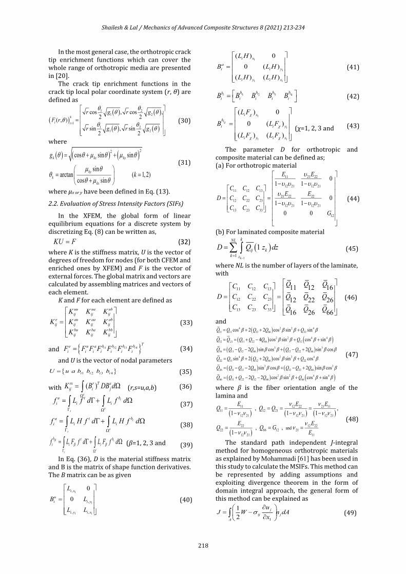
In the most general case, the orthotropic crack tip enrichment functions which can cover the whole range of orthotropic media are presented in [20].
The crack tip enrichment functions in the crack tip local polar coordinate system (r, θ) are defined as
( )( ) ( )
( ) ( )
1 21 2
4
11 2
1 2
cos , cos ,2 2
( , )
sin , sin2 2
t t
r g r g
F r
r g r g
=
=
(30)
where
( ) ( ) ( )22
cos sin sin
sinarctan ( 1,2)
cos sin
k kx ky
ky
k
kx
g
k
= + +
= =
+
(31)
where μx or y have been defined in Eq. (13).
2.2. Evaluation of Stress Intensity Factors (SIFs)
In the XFEM, the global form of linear equilibrium equations for a discrete system by discretizing Eq. (8) can be written as,
KU F= (32)
where K is the stiffness matrix, U is the vector of degrees of freedom for nodes (for both CFEM and enriched ones by XFEM) and F is the vector of external forces. The global matrix and vectors are calculated by assembling matrices and vectors of each element.
K and F for each element are defined as uu ua ub
ij ij ij
e au aa ab
ij ij ij ij
bu ba bb
ij ij ij
K K K
K K K K
K K K
=
(33)
and 1 2 3 4t t t tT
b b b be u a
i i i i i i iF F F F F F F= (34)
and U is the vector of nodal parameters
1 2 3 4t t t tU u a b b b b= (35)
with ( )e
rs r T s
ij i jK B DB d
= (r,s=u,a,b) (36)
t
et
bu t
i i if L f d L f d
= + (37)
t
et
ba t
i i if L H f d L H f d
= + (38)
t t
et
b bt
i i if L F f d L F f d
= + (β=1, 2, 3 and
4)
(39)
In Eq. (36), D is the material stiffness matrix and B is the matrix of shape function derivatives. The B matrix can be as given
1
1
1 1
,
,
, ,
0
0
i x
u
i i y
i y i x
L
B L
L L
=
(40)
1
1
1 1
( ) 0
0 ( )
( ) ( )
i x
a
i i y
i y i x
L H
B L H
L H L H
=
(41)
31 2 4tt t ttbb b bb
i i i i iB B B B B =
(42)
1
1
1 1
( ) 0
0 ( )
( ) ( )
t
i x
b
i i y
i y i x
L F
B L F
L F L F
=
(χ=1, 2, 3 and
4)
(43)
The parameter D for orthotropic and composite material can be defined as; (a) For orthotropic material
11 21 22
12 21 12 21
11 12 13
21 22 22
12 22 23
12 21 12 21
13 23 33
12
01 1
01 1
0 0
E E
C C CE E
D C C C
C C CG
− −
= = − −
(44)
(b) For laminated composite material
( )1
1
1
k
kNL
ij k
k z
D Q z dz
−=
= (45)
where NL is the number of layers of the laminate, with
11 12 13
12 22 23
13 23 33
11 12 16
12 22 26
16 26 66
Q Q QC C C
D C C C Q Q Q
C C C Q Q Q
= =
(46)
and ( )
( ) ( )
( ) ( )
( )
( )
4 2 2 4
11 11 12 66 22
2 2 4 4
12 11 22 66 1221
3 3
16 11 12 66 12 22 66
4 2 2 4
22 11 12 66 22
3
26 11 12 66
cos 2 2 cos sin sin
4 cos sin cos sin
2 sin cos 2 sin cos
sin 2 2 cos sin cos
2 sin cos
Q Q Q Q Q
Q Q Q Q Q Q
Q Q Q Q Q Q Q
Q Q Q Q Q
Q Q Q Q
= + + +
= = + − + +
= − − + − +
= + + +
= − − + ( )
( ) ( )
3
12 22 66
2 2 4 4
66 11 22 12 66 66
2 sin cos
2 2 cos sin cos sin
Q Q Q
Q Q Q Q Q Q
− +
= + − − + +
(47)
where β is the fiber orientation angle of the lamina and
( ) ( ) ( )
( )
11 12 22 21 11
11 12 21
12 21 12 21 12 21
22 12 22
22 66 12 21
12 21 11
and
, ,1 1 1
, ,1
E E EQ Q Q
E EQ Q G
E
= = = =− − −
= = =−
(48)
The standard path independent J-integral method for homogeneous orthotropic materials as explained by Mohammadi [61] has been used in this study to calculate the MSIFs. This method can be represented by adding assumptions and exploiting divergence theorem in the form of domain integral approach, the general form of this method can be explained as
1
1
2
j
ij j
A
uJ W n dA
x
= −
(49)
Shailesh & Lal / Mechanics of Advanced Composite Structures 8 (2021) 213-234
219
where A is the area surrounding the crack tip and would be the interior region of Γ as shown in Fig. 1, nj is jth component of the outward unit normal to A, W is the strain energy density,
1 1
2 2ij ij ijkl kl ijW C = = (50)
Using the equivalent domain integral, Eq. (49) can be transformed to
1
j
ij j
jA
u qJ W dA
x x
= −
(51)
where, Δ1j is the Kronecker delta and q is a simple function varying linearly from q=1 at the crack tip to q=0 at the exterior boundary ᴦ as shown in Fig. 1.
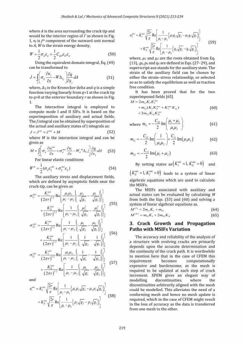
The interaction integral is employed to compute mode I and II SIFs. It is based on the superimposition of auxiliary and actual fields. The J integral can be obtained by superposition of the actual and auxiliary states of J integrals as:
act auxJ J J M= + + (52)
where M is the interaction integral and can be given as
1
aux
aux mi i
ij ij st J
jA
u u qM W dA
x x x
= + −
(53)
For linear elastic conditions
1( )
2
m aux aux
ij ij ij ijW = + (54)
The auxiliary stress and displacement fields, which are defined by asymptotic fields near the crack-tip, can be given as
( )
( )
1 2 2 1
11 1/2
1 2 2 1
2 2
2 1
1/2
1 2 2 1
Re2
1Re
2
aux
aux I
aux
II
K
g gr
K
g gr
= −
−
+ −
−
(55)
( )
( )
1 2
22 1/2
1 2 2 1
1/2
1 2 2 1
1Re
2
1 1 1Re
2
aux
aux I
aux
II
K
g gr
K
g gr
= −
−
+ −
−
(56)
( )
( )
1 2
12 1/2
1 2 1 2
1 2
1/2
1 2 1 2
1 1Re
2
1Re
2
aux
aux I
aux
II
K
g gr
K
g gr
= −
−
+ −
−
(57)
and
1 1 2 2 2 1 1
1 2
2 2 1 1
1 2
2 1Re
2 1Re
aux aux
I
aux
II
ru K p g p g
rK p g p g
= −
−
+ −
−
(58)
2 1 2 2 2 1 1
1 2
2 2 1 1
1 2
2 1Re
2 1Re
aux aux
I
aux
II
ru K q g q g
rK q g q g
= −
−
+ −
−
(59)
where, µ1 and µ2 are the roots obtained from Eq. (13), gk, pk and qk are defined in Eqs. (27- 29), and superscript aux stands for the auxiliary state. The strain of the auxiliary field can be chosen by either the strain–stress relationship, or selected so as to satisfy the equilibrium as well as traction free condition.
It has been proved that for the two superimposed fields [65]
11
12
22
2
( )
2
aux
I I
aux aux
I II I II
aux
II II
M m K K
m K K K K
m K K
=
+ +
+
(60)
where 22 1 2
11
1 2
Im2
Cm
+= −
(61)
( )22 11
12 1 2
1 2
1Im Im
2 2
C Cm
= − +
(62)
( )11
22 1 2Im2
Cm = − + (63)
By setting states as ( )1, 0aux aux
I IIK K= = and
( )1, 0aux aux
II IK K= = leads to a system of linear
algebraic equations which are used to calculate the MSIFs.
The MSIFs associated with auxiliary and actual states can be evaluated by calculating M from both the Eqs. (53) and (60) and solving a system of linear algebraic equations as.
( )
11 122I
IM m K m= + (64) ( )
12 222II
I IIM m K m K= + (65)
3. Crack Growth and Propagation Paths with MSIFs Variation
The accuracy and reliability of the analysis of a structure with evolving cracks are primarily depends upon the accurate determination and the continuity of the crack path. It is worthwhile to mention here that in the case of CFEM this requirement becomes computationally expensive and burdensome, as the mesh is required to be updated at each step of crack increment. XFEM gives an elegant way of modelling discontinuities, where the discontinuities arbitrarily aligned with the mesh could be modelled. This alleviates the need of a conforming mesh and hence no mesh update is required, which in the case of CFEM might result in the loss of accuracy as the data is transferred from one mesh to the other.
Shailesh & Lal / Mechanics of Advanced Composite Structures 8 (2021) 213-234
220
It is therefore very much essential to select the crack growth criteria very carefully. Some of the commonly used crack growth criteria/ algorithms are: I. Minimum strain energy density criteria proposed by Sih [66] II. Maximum energy release rate criteria proposed by Nuismer [67] III. Maximum hoop stress or maximum principal stress criteria proposed by Erdogan and Sih [68] IV. The global tracking algorithm proposed by Oliver et al. [69].
The first three criteria/ algorithms are widely used in CFEM. In these algorithms, the basic requirement is that the algorithm is needed to be evaluated for each individual crack growth segment, which is an expensive and may result in inaccuracy as discussed earlier.
In contrast to these tracking algorithms, Global tracking crack growth algorithm proposed by Oliver et al. [69- 70] traces all discontinuity paths at once and does not need to be evaluated at each individual crack propagation step. This algorithm shows good results [71- 72] in predicting crack paths and can be easily and elegantly incorporated in the XFEM algorithm. The basic idea is to construct a scalar function ψ whose isolines run perpendicular to the direction of principal stresses in all integration points of the investigated structure. However, this comes at the cost of solving additional global system of equations with one degree of freedom per node. An Iso-line is then defined as
( ) Yi iY x x = = (66)
If crack growth is indicated by the crack propagation criterion, the value of ψ is calculated at the crack tip. The crack is then extended following the isoline corresponding to this value of ψ. The crack growth criterion which is used for present analyses is an energy-based crack propagation criterion proposed by Xie and Gerstle [73]. According to this criterion the crack propagation condition can be given as follows,
0 nocrack propagation
0 stationarycrack propagation
0 crack propagationcrA
→
= →
→
(67)
where Acr is the area of a new crack segment.
4. Numerical Examples
In this section, several numerical examples are presented by developing a computer code in MATLAB. From the literature available it is being observed that, in the investigation of the effects of biaxially applied stresses, MSIFs are considered among the important parameters for fracture analysis and also for the determination of the path of crack propagation. Therefore, firstly to
show the accuracy of MATLAB code developed for implementation of XFEM algorithm to handle various fracture problems, the MSIFs are calculated and compared with the exact solution and those available in the literature, and then in the further study the effect of different types of biaxially applied stresses like tensile, shear and tensile and shear combined on the MSIFs by varying the load and crack parameters along with crack propagation paths is studied.
In all the examples considered in this study, the following average material parameters which are being the functions of independent engineering constants (Eij, υij, Gij, i, j = 1, 2) are used for all orthotropic and laminated composite plates as suggested by Mohammadi [60]
11 22 12 21
4 11 12
22 21 12
,
,2
E E E
E E
E G
= =
= = = −
(68)
where E' is the efficient Young’s modulus, ν' is the effective Poisson’s ratio, δ4 is the stiffness ratio, and κ' is the shear parameter.
The following normalized MSIFs, KI and KII are used in the present analysis unless otherwise mentioned, and
for tensile stress I I
II II
K K a
K K a
=
=
(69)
for shear stress I I
II II
K K a
K K a
=
=
(70)
( )for combined tensile shear stress I I
II II
K K a
K K a
= +
=
(71)
where IK and
IIK are the first and second mode
SIFs, the parameter σ, τ and ϛ are the tensile, shear and combined (tensile + shear) stresses respectively, which are assumed as unity, as the thickness of the plate considered is unity for the present analysis (unless otherwise mentioned) and the parameter a is a semi crack length.
4.1. Convergence and Validation of Present Study
For validating the present computer program developed for XFEM algorithm, the program is firstly applied to standard test problem. In this example, a finite plate of isotropic material having material parameters as E = 200 GPa and υ = 0.3 with an inclined central crack under biaxial stress as explained by Tabarraei and Sukumar [10] is considered. A square plate with height H (=5 mm), width W (=5 mm) and unit thickness with centrally located inclined crack with the crack angle α measured with the Y-axis and the semi crack length a=1mm is considered. The plate is subjected to uniformly applied tensile stress of KσX =1 MPa with K (=0.5) and σY = 2 MPa
Shailesh & Lal / Mechanics of Advanced Composite Structures 8 (2021) 213-234
221
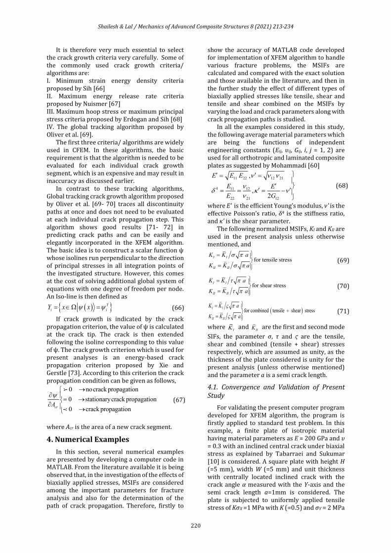
in the X- and Y-directions respectively is shown in Fig. 2 (a). The factor K is the biaxial load factor, which is defined as the ratio of the load applied parallel to the crack to that applied perpendicular to it, where the crack is aligned with the X or Y coordinate axis. The meshing, modelling of the plate and elements selected for the enrichment of the crack face and crack tips are shown in Fig. 2 (b-c).
For the accuracy point of view, convergence studies of various structured meshes are carried out. It is evident from the Table 1 that the present computations of MSIFs for the plate with an inclined center crack with crack angle (α =40°) as explained in the literature [10] are converged well for the 4 nodes quadrilateral elements with mesh size of 40 x 40 elements. Therefore, for further computations, 40 x 40 number of element mesh is used. The interaction integral with semi crack length ae is calculated within the domain of size 3d er a= as the values of the SIFs become
nearly independent of the domain size [61]. The exact stress intensity factors which are
the functions of the crack angle α and as given by Tabarraei and Sukumar [10] are
( )2 2sin cosI Y XK a = + (72)
( )sin cosII Y XK a = − (73)
It should be noted here that the exact values of stress intensity factors mentioned by Tabarraei and Sukumar [10] are for an infinite plate, and as the problem at hand has the plate dimensions quite large as compared to the crack length used for analysis, therefore the numerical solution can be compared with the exact solution and results given in [10].
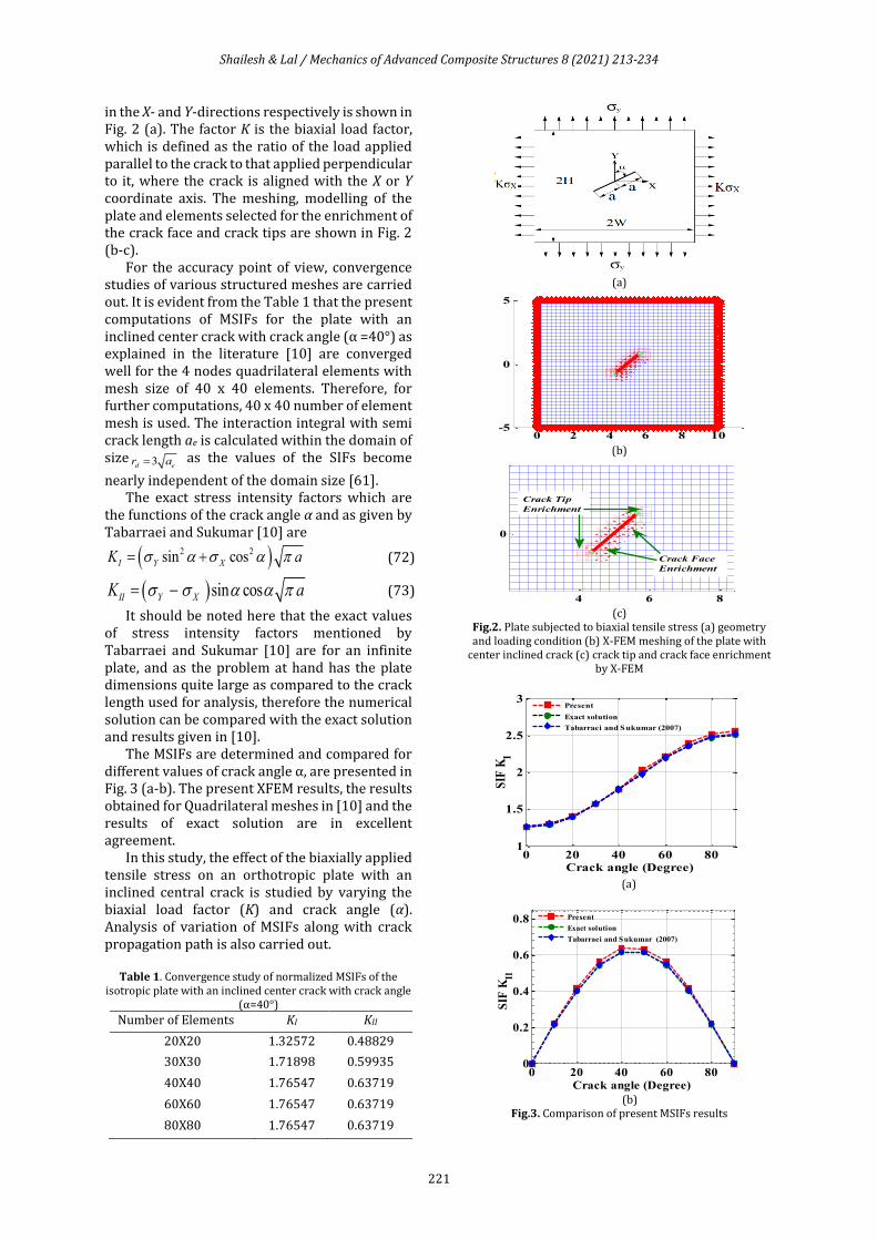
The MSIFs are determined and compared for different values of crack angle α, are presented in Fig. 3 (a-b). The present XFEM results, the results obtained for Quadrilateral meshes in [10] and the results of exact solution are in excellent agreement.
In this study, the effect of the biaxially applied tensile stress on an orthotropic plate with an inclined central crack is studied by varying the biaxial load factor (K) and crack angle (α). Analysis of variation of MSIFs along with crack propagation path is also carried out.
Table 1. Convergence study of normalized MSIFs of the
isotropic plate with an inclined center crack with crack angle (α=40°)
Number of Elements KI KII
20X20 1.32572 0.48829
30X30 1.71898 0.59935
40X40 1.76547 0.63719
60X60 1.76547 0.63719
80X80 1.76547 0.63719
(a)
(b)
(c)
Fig.2. Plate subjected to biaxial tensile stress (a) geometry and loading condition (b) X-FEM meshing of the plate with
center inclined crack (c) crack tip and crack face enrichment by X-FEM
(a)
(b)
Fig.3. Comparison of present MSIFs results
0 2 4 6 8 10-5
0
5
4 6 8
0
Crack Tip
Enrichment
Crack Face
Enrichment
0 20 40 60 801
1.5
2
2.5
3
Crack angle (Degree)
SIF
KI
Present
Exact solution
Tabarraei and Sukumar (2007)
0 20 40 60 800
0.2
0.4
0.6
0.8
Crack angle (Degree)
SIF
KII
Present
Exact solution
Tabarraei and Sukumar (2007)
Shailesh & Lal / Mechanics of Advanced Composite Structures 8 (2021) 213-234
222
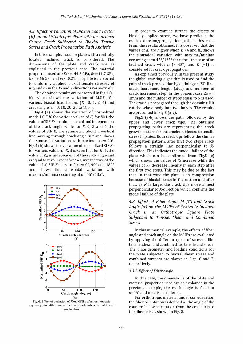
4.2. Effect of Variation of Biaxial Load Factor (K) on an Orthotropic Plate with an Inclined Centre Crack Subjected to Biaxial Tensile Stress and Crack Propagation Path Analysis.
In this example, a square plate with a centrally located inclined crack is considered. The dimensions of the plate and crack are as explained in the previous case. The material properties used are E11 =144.8 GPa, E22=11.7 GPa, G12=9.66 GPa and υ12 =0.21. The plate is subjected to uniformly applied biaxial tensile stresses of KσX and σY in the X- and Y-directions respectively.
The obtained results are presented in Fig.4 (a-b), which shows the variation of MSIFs for various biaxial load factors (K= 0, 1, 2, 4) and crack angle (α =0, 10, 20, 30 to 180°).
Fig.4 (a) shows the variation of normalized mode I SIF KI for various values of K, for K=1 the values of SIF KI are almost equal and independent of the crack angle while for K=0, 2 and 4 the values of SIF KI are symmetric about a vertical line passing through crack angle 90° and shows the sinusoidal variation with maxima at α= 90°. Fig.4 (b) shows the variation of normalized SIF KII for various values of K, it is seen that for K=1, the value of KII is independent of the crack angle and is equal to zero. Except for K=1, irrespective of the value of K, SIF KII is zero for α= 0°, 90° and 180° and shows the sinusoidal variation with maxima/minima occurring at α= 45°/135°.
(a)
(b)
Fig.4. Effect of variation of K on MSIFs of an orthotropic square plate with a center inclined crack subjected to biaxial
tensile stress
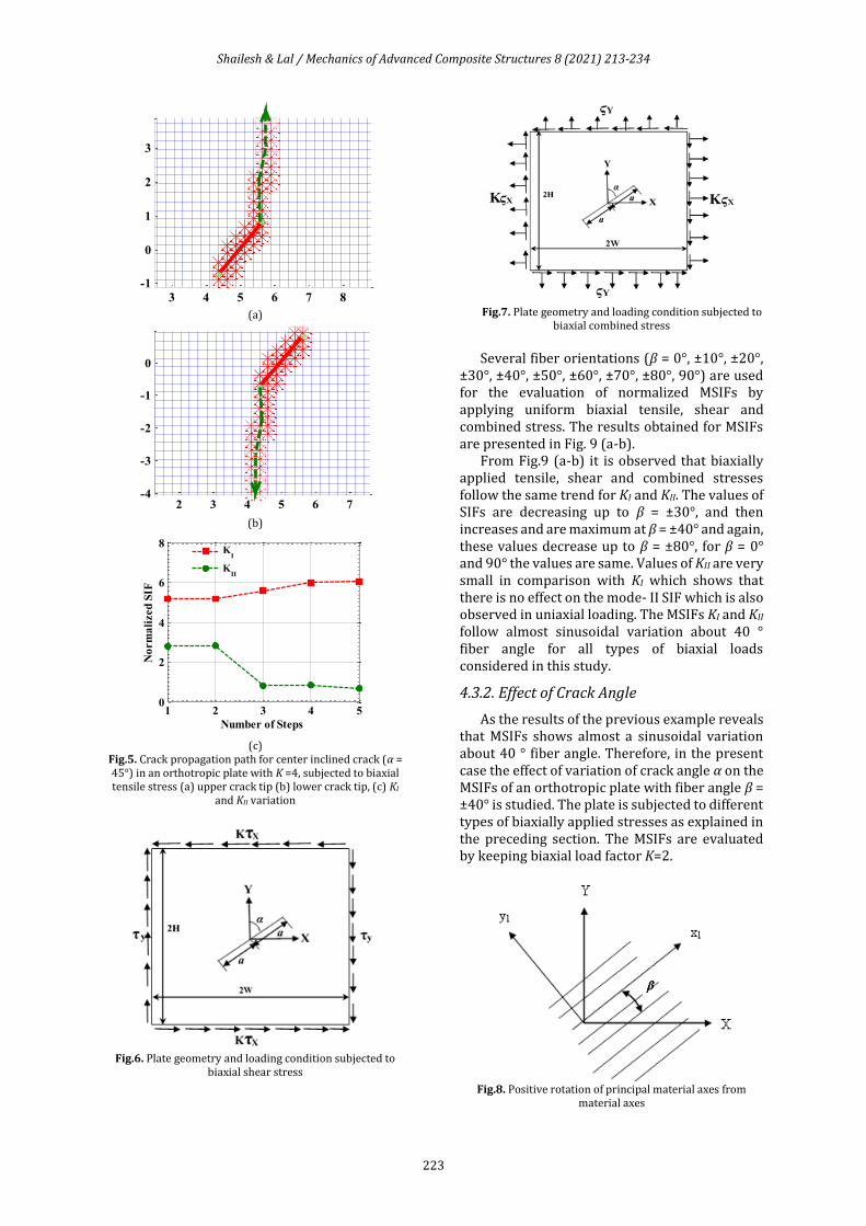
In order to examine further the effects of biaxially applied stress, we have predicted the crack extension/propagation path in this case. From the results obtained, it is observed that the values of KI are higher when K =4 and KII shows the sinusoidal variation with maxima/minima occurring at α= 45°/135° therefore, the case of an inclined crack with α (= 45°) and K (=4) is considered for crack propagation.
As explained previously, in the present study the global tracking algorithm is used to find the path of crack propagation by defining an ISO-line, crack increment length (Δincr) and number of crack increment step. In the present case Δincr = 1mm and the number of steps equal to 5 is used. The crack is propagated through the domain till it cut the whole body into two halves. The results are presented in Fig.5 (a-c).
Fig.5 (a-b) shows the path followed by the upper and lower crack tips. The obtained propagating paths are representing the crack growth pattern for the cracks subjected to tensile stress in plates. Both crack tips follow the similar propagation pattern, after first two steps crack follows a straight line perpendicular to X-direction. This indicates the mode I failure of the plate which can be confirmed from Fig.5 (c) which shows the values of KI increase while the values of KII decrease linearly in each step after the first two steps. This may be due to the fact that, in that zone the plate is in compression because of biaxial stress in Y-direction and after that, as K is large, the crack tips move almost perpendicular to X-direction which confirms the mode I failure of the plate.
4.3. Effect of Fiber Angle (± β°) and Crack Angle (α) on the MSIFs of Centrally Inclined Crack in an Orthotropic Square Plate Subjected to Tensile, Shear and Combined Stress
In this numerical example, the effects of fiber angle and crack angle on the MSIFs are evaluated by applying the different types of stresses like tensile, shear and combined i.e., tensile and shear. The plate geometry and loading conditions for the plate subjected to biaxial shear stress and combined stresses are shown in Figs. 6 and 7, respectively.
4.3.1. Effect of Fiber Angle
In this case, the dimensions of the plate and material properties used are as explained in the previous example, the crack angle is fixed at α=45° and K =2 is considered.
For orthotropic material under consideration the fiber orientation is defined as the angle of the counterclockwise rotation from the crack axis to the fiber axis as shown in Fig. 8.
0 50 100 150-1
0
1
2
3
4
5
6
Crack angle (degree)
No
rma
lize
d S
IF K
I
K=0
K=1
K=2
K=4
0 50 100 150-3
-2
-1
0
1
2
3
Crack angle (degree)
No
rma
lize
d S
IF K
II
K=0
K=1
K=2
K=4
Shailesh & Lal / Mechanics of Advanced Composite Structures 8 (2021) 213-234
223
(a)
(b)
(c)
Fig.5. Crack propagation path for center inclined crack (α = 45°) in an orthotropic plate with K =4, subjected to biaxial tensile stress (a) upper crack tip (b) lower crack tip, (c) KI
and KII variation
Fig.6. Plate geometry and loading condition subjected to
biaxial shear stress
Fig.7. Plate geometry and loading condition subjected to
biaxial combined stress
Several fiber orientations (β = 0°, ±10°, ±20°,
±30°, ±40°, ±50°, ±60°, ±70°, ±80°, 90°) are used for the evaluation of normalized MSIFs by applying uniform biaxial tensile, shear and combined stress. The results obtained for MSIFs are presented in Fig. 9 (a-b).
From Fig.9 (a-b) it is observed that biaxially applied tensile, shear and combined stresses follow the same trend for KI and KII. The values of SIFs are decreasing up to β = ±30°, and then increases and are maximum at β = ±40° and again, these values decrease up to β = ±80°, for β = 0° and 90° the values are same. Values of KII are very small in comparison with KI which shows that there is no effect on the mode- II SIF which is also observed in uniaxial loading. The MSIFs KI and KII follow almost sinusoidal variation about 40 ° fiber angle for all types of biaxial loads considered in this study.
4.3.2. Effect of Crack Angle
As the results of the previous example reveals that MSIFs shows almost a sinusoidal variation about 40 ° fiber angle. Therefore, in the present case the effect of variation of crack angle α on the MSIFs of an orthotropic plate with fiber angle β = ±40° is studied. The plate is subjected to different types of biaxially applied stresses as explained in the preceding section. The MSIFs are evaluated by keeping biaxial load factor K=2.
Fig.8. Positive rotation of principal material axes from
material axes
3 4 5 6 7 8
-1
0
1
2
3
2 3 4 5 6 7-4
-3
-2
-1
0
1 2 3 4 50
2
4
6
8
Number of Steps
No
rm
ali
zed
SIF
K
I
KII
Shailesh & Lal / Mechanics of Advanced Composite Structures 8 (2021) 213-234
224
(a)
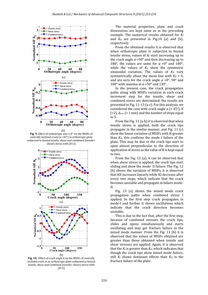
(b)
Fig. 9. Effect of orthotropic axis ± β ° on the MSIFs of centrally inclined crack (α =45°) in orthotropic plate
subjected to biaxial tensile, shear and combined (tensile+ shear) stress with (K=2)
(a)
(b)
Fig. 10. Effect of crack angle α on the MSIFs of centrally inclined crack in an orthotropic plate subjected to biaxial tensile, shear and combined (tensile+ shear) stress with
(K=2)
The material properties, plate and crack dimensions are kept same as in the preceding example. The numerical results obtained for KI and KII are presented in Fig.10 (a) and (b), respectively.
From the obtained results it is observed that when orthotropic plate is subjected to biaxial tensile stress, values of KI start increasing up to the crack angle α =90° and then decreasing up to 180°, the values are same for α =0° and 180°, while the values of KII show the symmetric sinusoidal variation. The values of KII vary symmetrically about the mean line with KII = 0, and are zero for the crack angle α =0°, 90° and 180° with maxima at α =50° and 130°.
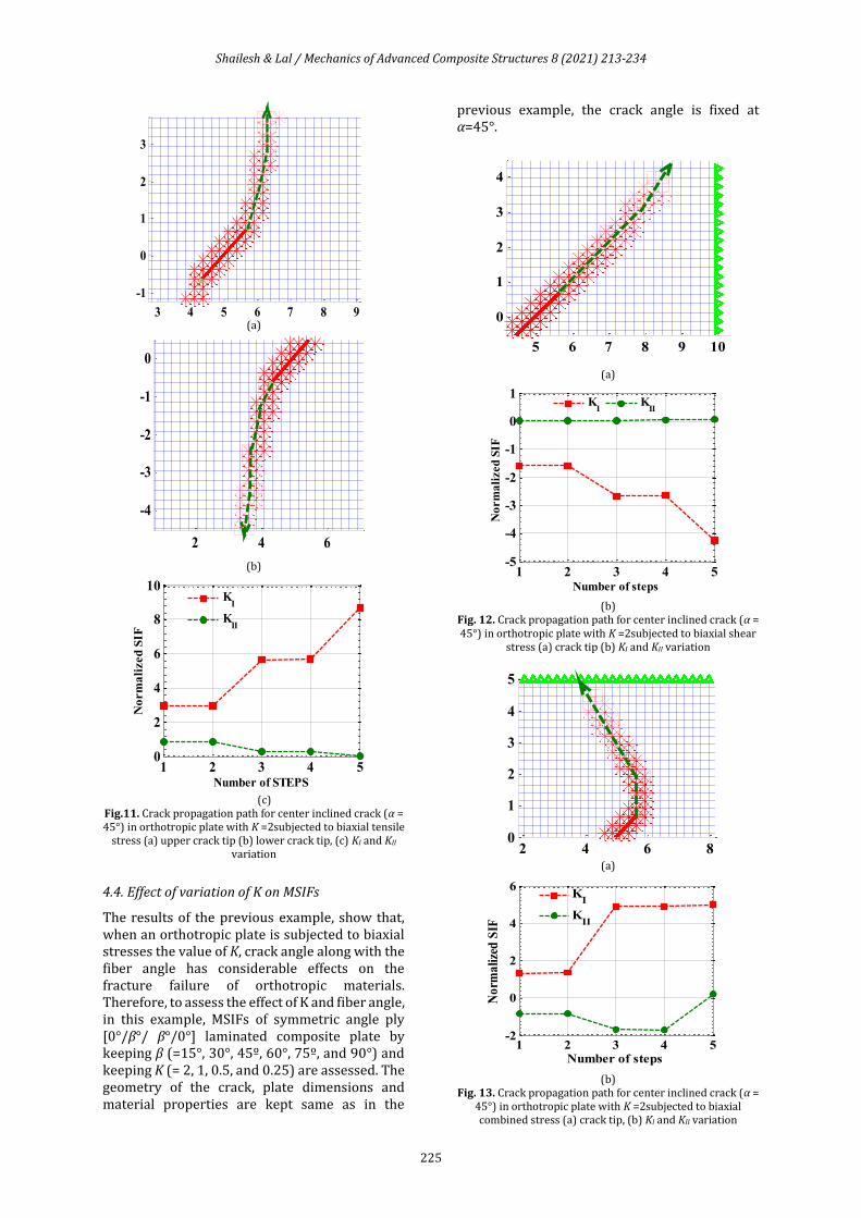
In the present case, the crack propagation paths along with MSIFs variation in each crack increment step for the tensile, shear and combined stress are determined; the results are presented in Fig. 11-13 (a-c). For this analysis, we considered the case with crack angle α (= 45°), K (=2), Δincr (= 1 mm) and the number of steps equal to 5.
From the Fig. 11 (a-b) it is observed that when tensile stress is applied, both the crack tips propagate in the similar manner, and Fig. 11 (c) show the linear variation of MSIFs with KI greater than KII, this confirms the mode I failure of the plate. This may be due to the crack tips start to open almost perpendicular to the direction of application of stress as the value of K is kept equal to two.
From the Fig. 12 (a), it can be observed that when shear stress is applied, the crack tips start sliding and show the mode- II failure. The Fig. 12 (b) shows the variation of MSIFs, it is observed that KII increases linearly while KI decrease after every two steps, which indicate that the crack becomes unstable and propagate in failure mode- II.
Fig. 13 (a) shows the mixed mode crack propagation paths when combined stress I applied. In the first step crack propagates in mode-I and further it shows oscillations which indicate that the crack direction becomes unstable.
This is due to the fact that, after the first step, because of combined stresses the crack tips, slides and opens simultaneously and starts oscillating and may get fracture failure in the mixed mode manner. From the Fig. 13 (b) it is observed that the values of MSIFs obtained are greater than those obtained when tensile and shear stresses are applied. Again, it is observed that the KI is greater than KII, which indicates that though the crack tips show mixed mode failure, still KI shows dominant effects than KII in the fracture failure of the plate.
0 20 40 60 80
-1
0
1
2
3
Orthotropic angle (degree)
No
rma
lize
d S
IF K
I
Tensile stress
Shear stress
Combined stress
0 20 40 60 80
-0.8
-0.6
-0.4
-0.2
0
Orthotropic angle (degree)
No
rma
lize
d S
IF K
II
Tensile stress
Shear stress
Combined stress
0 50 100 150-1
0
1
2
3
4
Crack angle (degree)
No
rma
lize
d S
IF K
I
Tensile stress
Shear stress
Combined stress
0 50 100 150-1.5
-1
-0.5
0
0.5
1
Crack angle (degree)
No
rm
ali
zed
SIF
KII
Tensile stress
Shear stress
Combined stress
Shailesh & Lal / Mechanics of Advanced Composite Structures 8 (2021) 213-234
225
(a)
(b)
(c)
Fig.11. Crack propagation path for center inclined crack (α = 45°) in orthotropic plate with K =2subjected to biaxial tensile
stress (a) upper crack tip (b) lower crack tip, (c) KI and KII variation
4.4. Effect of variation of K on MSIFs
The results of the previous example, show that, when an orthotropic plate is subjected to biaxial stresses the value of K, crack angle along with the fiber angle has considerable effects on the fracture failure of orthotropic materials. Therefore, to assess the effect of K and fiber angle, in this example, MSIFs of symmetric angle ply [0°/β°/ β°/0°] laminated composite plate by keeping β (=15°, 30°, 45º, 60°, 75º, and 90°) and keeping K (= 2, 1, 0.5, and 0.25) are assessed. The geometry of the crack, plate dimensions and material properties are kept same as in the
previous example, the crack angle is fixed at α=45°.
(a)
(b)
Fig. 12. Crack propagation path for center inclined crack (α = 45°) in orthotropic plate with K =2subjected to biaxial shear
stress (a) crack tip (b) KI and KII variation
(a)
(b)
Fig. 13. Crack propagation path for center inclined crack (α = 45°) in orthotropic plate with K =2subjected to biaxial combined stress (a) crack tip, (b) KI and KII variation
3 4 5 6 7 8 9
-1
0
1
2
3
2 4 6
-4
-3
-2
-1
0
1 2 3 4 50
2
4
6
8
10
Number of STEPS
No
rm
ali
zed
SIF
K
I
KII
5 6 7 8 9 10
0
1
2
3
4
1 2 3 4 5-5
-4
-3
-2
-1
0
1
Number of steps
No
rm
ali
zed
SIF
K
IK
II
2 4 6 80
1
2
3
4
5
1 2 3 4 5-2
0
2
4
6
Number of steps
No
rma
lize
d S
IF
K
I
KII
Shailesh & Lal / Mechanics of Advanced Composite Structures 8 (2021) 213-234
226
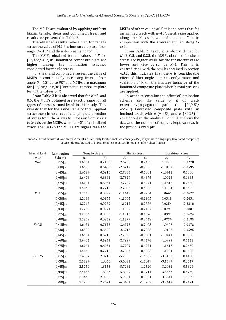
The MSIFs are evaluated by applying uniform biaxial tensile, shear and combined stress, and results are presented in Table 2.
The obtained results reveal that, for tensile stress the value of MSIF is increased up to a fiber angle β = 45° and then decreasing up to 90°.
The MSIFs obtained for all values of K for [0°/45°/ 45°/0°] laminated composite plate are higher among the lamination schemes considered for tensile stress.
For shear and combined stresses, the value of MSIFs is continuously increasing from a fiber angle β = 15° up to 90° and MSIFs are maximum for [0°/90°/ 90°/0°] laminated composite plate for all the values of K.
From Table 2 it is observed that for K =2, and 0.5, the MSIFs obtained are exactly same for all types of stresses considered in this study. This reveals that for the same value of total applied stress there is no effect of changing the direction of stress from the X-axis to Y-axis or from Y-axis to X-axis on the MSIFs when α=45° of an inclined crack. For K=0.25 the MSIFs are higher than the
MSIFs of other values of K, this indicates that for an inclined crack with α=45°, the stresses applied along the Y-axis have a dominant effect in comparison with the stresses applied along X-axis.
From Table 2, again, it is observed that for K =2, 0.5, and 0.25, the MSIFs obtained for shear stress are higher while for the tensile stress are lower and vice versa for K=1. This is in contradiction with the results obtained in section 4.3.2; this indicates that there is considerable effect of fiber angle, lamina configuration and variation of K on the fracture behavior of the laminated composite plate when biaxial stresses are applied.
In order to examine the effect of lamination scheme and the value of K on crack extension/propagation path, the [0°/45°/ 45°/0°] laminated composite plate with an inclined crack with α (= 45°) and K (=0.25) is considered in the analysis. For this analysis the Δincr and the number of steps is kept same as in the previous example.
Table 2. Effect of biaxial load factor K on SIFs of centrally located inclined crack (α=45°) in symmetric angle ply laminated composite square plate subjected to biaxial tensile, shear, combined (Tensile + shear) stress
Biaxial load factor
Lamination Scheme
Tensile stress Shear stress Combined stress
KI KII KI KII KI KII
K=2
[0/15]2S 1.6191 0.7125 -2.6798 -0.7403 -1.0607 -0.0278
[0/30]2S 1.6530 0.6458 -2.6717 -0.7053
-1.0187 -0.0595
[0/45]2S 1.6594 0.6210
-2.7035 -0.5881 -1.0441
0.0330
[0/60]2S 1.6406 0.6341 -2.7329
-0.4676 -1.0923 0.1665
[0/75]2S 1.6091 0.6951 -2.7709
-0.4271 -1.1618 0.2680
[0/90]2S 1.5869 0.7716 -2.7853 -0.6033
-1.1984 0.1683
K=1 [0/15]2S 1.2110 0.0332 -1.1445 -0.2954 0.0665 -0.2622
[0/30]2S 1.2183 0.0255 -1.1665 -0.2905 0.0518 -0.2651
[0/45]2S 1.2265 0.0239
-1.1912 -0.2556
0.0354
-0.2318
[0/60]2S 1.2286 0.0271 -1.1989 -0.2157 0.0297 -0.1887
[0/75]2S 1.2306 0.0302 -1.1913 -0.1976 0.0393 -0.1674
[0/90]2S 1.2309 0.0263 -1.1579 -0.2448 0.0730 -0.2185
K=0.5 [0/15]2S 1.6191 0.7125 -2.6798 -0.7403
-1.0607 -0.0278
[0/30]2S 1.6530 0.6458 -2.6717 -0.7053
-1.0187
-0.0595
[0/45]2S 1.6594 0.6210 -2.7035 -0.5881
-1.0441
0.0330
[0/60]2S 1.6406 0.6341 -2.7329 -0.4676 -1.0923 0.1665
[0/75]2S 1.6091 0.6951 -2.7709 -0.4271 -1.1618
0.2680
[0/90]2S 1.5869 0.7716 -2.7853 -0.6033 -1.1984 0.1683
K=0.25 [0/15]2S 2.4352 2.0710 -5.7505 -1.6302 -3.3152 0.4408
[0/30]2S 2.5224 1.8866 -5.6821
-1.5349 -3.1597 0.3517
[0/45]2S 2.5250 1.8153 -5.7281 -1.2529 -3.2031 0.5624
[0/60]2S 2.4646 1.8483 -5.8009 -0.9714
-3.3363
0.8769
[0/75]2S 2.3660 2.0250
-5.9301 -0.8861 -3.5641 1.1389
[0/90]2S 2.2988 2.2624 -6.0401
-1.3203 -3.7413 0.9421
Shailesh & Lal / Mechanics of Advanced Composite Structures 8 (2021) 213-234
227
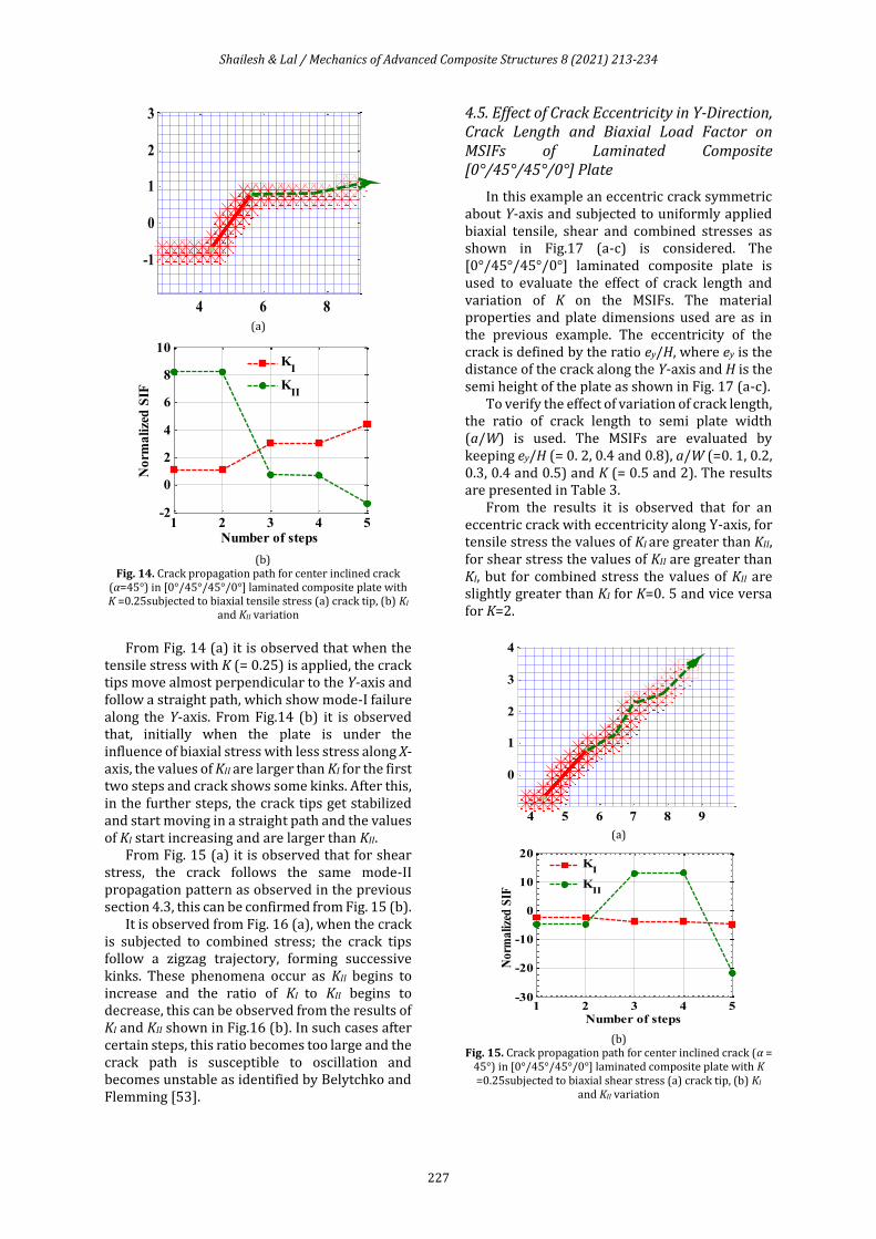
(a)
(b)
Fig. 14. Crack propagation path for center inclined crack (α=45°) in [0°/45°/45°/0°] laminated composite plate with K =0.25subjected to biaxial tensile stress (a) crack tip, (b) KI
and KII variation
From Fig. 14 (a) it is observed that when the
tensile stress with K (= 0.25) is applied, the crack tips move almost perpendicular to the Y-axis and follow a straight path, which show mode-I failure along the Y-axis. From Fig.14 (b) it is observed that, initially when the plate is under the influence of biaxial stress with less stress along X-axis, the values of KII are larger than KI for the first two steps and crack shows some kinks. After this, in the further steps, the crack tips get stabilized and start moving in a straight path and the values of KI start increasing and are larger than KII.
From Fig. 15 (a) it is observed that for shear stress, the crack follows the same mode-II propagation pattern as observed in the previous section 4.3, this can be confirmed from Fig. 15 (b).
It is observed from Fig. 16 (a), when the crack is subjected to combined stress; the crack tips follow a zigzag trajectory, forming successive kinks. These phenomena occur as KII begins to increase and the ratio of KI to KII begins to decrease, this can be observed from the results of KI and KII shown in Fig.16 (b). In such cases after certain steps, this ratio becomes too large and the crack path is susceptible to oscillation and becomes unstable as identified by Belytchko and Flemming [53].
4.5. Effect of Crack Eccentricity in Y-Direction, Crack Length and Biaxial Load Factor on MSIFs of Laminated Composite [0°/45°/45°/0°] Plate
In this example an eccentric crack symmetric about Y-axis and subjected to uniformly applied biaxial tensile, shear and combined stresses as shown in Fig.17 (a-c) is considered. The [0°/45°/45°/0°] laminated composite plate is used to evaluate the effect of crack length and variation of K on the MSIFs. The material properties and plate dimensions used are as in the previous example. The eccentricity of the crack is defined by the ratio ey/H, where ey is the distance of the crack along the Y-axis and H is the semi height of the plate as shown in Fig. 17 (a-c).
To verify the effect of variation of crack length, the ratio of crack length to semi plate width (a/W) is used. The MSIFs are evaluated by keeping ey/H (= 0. 2, 0.4 and 0.8), a/W (=0. 1, 0.2, 0.3, 0.4 and 0.5) and K (= 0.5 and 2). The results are presented in Table 3.
From the results it is observed that for an eccentric crack with eccentricity along Y-axis, for tensile stress the values of KI are greater than KII, for shear stress the values of KII are greater than KI, but for combined stress the values of KII are slightly greater than KI for K=0. 5 and vice versa for K=2.
(a)
(b)
Fig. 15. Crack propagation path for center inclined crack (α = 45°) in [0°/45°/45°/0°] laminated composite plate with K =0.25subjected to biaxial shear stress (a) crack tip, (b) KI
and KII variation
4 6 8
-1
0
1
2
3
1 2 3 4 5-2
0
2
4
6
8
10
Number of steps
No
rma
lize
d S
IF
KI
KII
4 5 6 7 8 9
0
1
2
3
4
1 2 3 4 5-30
-20
-10
0
10
20
Number of steps
No
rma
lize
d S
IF
K
I
KII
Shailesh & Lal / Mechanics of Advanced Composite Structures 8 (2021) 213-234
228
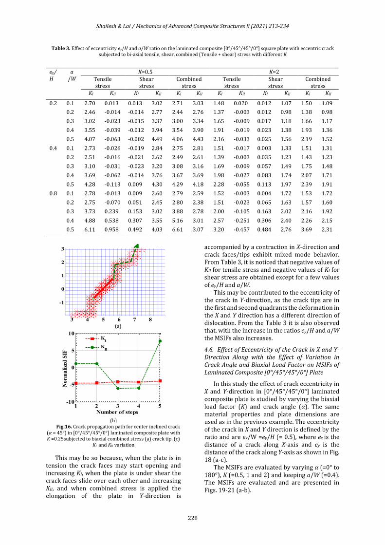
Table 3. Effect of eccentricity ey/H and a/W ratio on the laminated composite [0°/45°/45°/0°] square plate with eccentric crack subjected to bi-axial tensile, shear, combined (Tensile + shear) stress with different K
ey/H
a /W
K=0.5 K=2 Tensile stress
Shear stress
Combined stress
Tensile stress
Shear stress
Combined stress
KI KII KI KII KI KII KI KII KI KII KI KII
0.2 0.1 2.70 0.013 0.013 3.02 2.71 3.03 1.48 0.020 0.012 1.07 1.50 1.09
0.2 2.46 -0.014 -0.014 2.77 2.44 2.76 1.37 -0.003 0.012 0.98 1.38 0.98
0.3 3.02 -0.023 -0.015 3.37 3.00 3.34 1.65 -0.009 0.017 1.18 1.66 1.17
0.4 3.55 -0.039 -0.012 3.94 3.54 3.90 1.91 -0.019 0.023 1.38 1.93 1.36
0.5 4.07 -0.063 -0.002 4.49 4.06 4.43 2.16 -0.033 0.025 1.56 2.19 1.52
0.4 0.1 2.73 -0.026 -0.019 2.84 2.75 2.81 1.51 -0.017 0.003 1.33 1.51 1.31
0.2 2.51 -0.016 -0.021 2.62 2.49 2.61 1.39 -0.003 0.035 1.23 1.43 1.23
0.3 3.10 -0.031 -0.023 3.20 3.08 3.16 1.69 -0.009 0.057 1.49 1.75 1.48
0.4 3.69 -0.062 -0.014 3.76 3.67 3.69 1.98 -0.027 0.083 1.74 2.07 1.71
0.5 4.28 -0.113 0.009 4.30 4.29 4.18 2.28 -0.055 0.113 1.97 2.39 1.91
0.8 0.1 2.78 -0.013 0.009 2.60 2.79 2.59 1.52 -0.003 0.004 1.72 1.53 1.72
0.2 2.75 -0.070 0.051 2.45 2.80 2.38 1.51 -0.023 0.065 1.63 1.57 1.60
0.3 3.73 0.239 0.153 3.02 3.88 2.78 2.00 -0.105 0.163 2.02 2.16 1.92
0.4 4.88 0.538 0.307 3.55 5.16 3.01 2.57 -0.251 0.306 2.40 2.26 2.15
0.5 6.11 0.958 0.492 4.03 6.61 3.07 3.20 -0.457 0.484 2.76 3.69 2.31
(a)
(b)
Fig.16. Crack propagation path for center inclined crack (α = 45°) in [0°/45°/45°/0°] laminated composite plate with K =0.25subjected to biaxial combined stress (a) crack tip, (c)
KI and KII variation
This may be so because, when the plate is in tension the crack faces may start opening and increasing KI, when the plate is under shear the crack faces slide over each other and increasing KII, and when combined stress is applied the elongation of the plate in Y-direction is
accompanied by a contraction in X-direction and crack faces/tips exhibit mixed mode behavior. From Table 3, it is noticed that negative values of KII for tensile stress and negative values of KI for shear stress are obtained except for a few values of ey/H and a/W.
This may be contributed to the eccentricity of the crack in Y-direction, as the crack tips are in the first and second quadrants the deformation in the X and Y direction has a different direction of dislocation. From the Table 3 it is also observed that, with the increase in the ratios ey/H and a/W the MSIFs also increases.
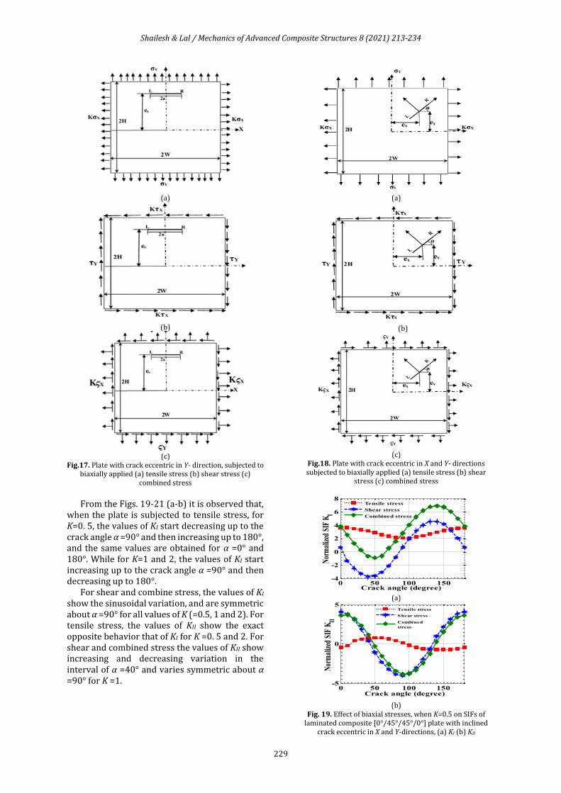
4.6. Effect of Eccentricity of the Crack in X and Y-Direction Along with the Effect of Variation in Crack Angle and Biaxial Load Factor on MSIFs of Laminated Composite [0°/45°/45°/0°] Plate
In this study the effect of crack eccentricity in X and Y-direction in [0°/45°/45°/0°] laminated composite plate is studied by varying the biaxial load factor (K) and crack angle (α). The same material properties and plate dimensions are used as in the previous example. The eccentricity of the crack in X and Y direction is defined by the ratio and are ex/W =ey/H (= 0.5), where ex is the distance of a crack along X-axis and ey is the distance of the crack along Y-axis as shown in Fig. 18 (a-c).
The MSIFs are evaluated by varying α (=0° to 180°), K (=0.5, 1 and 2) and keeping a/W (=0.4). The MSIFs are evaluated and are presented in Figs. 19-21 (a-b).
3 4 5 6 7 8
-1
0
1
2
3
1 2 3 4 5-10
-5
0
5
10
Number of steps
No
rma
lize
d S
IF
K
I
KII
Shailesh & Lal / Mechanics of Advanced Composite Structures 8 (2021) 213-234
229
(a)
(b)
(c)
Fig.17. Plate with crack eccentric in Y- direction, subjected to biaxially applied (a) tensile stress (b) shear stress (c)
combined stress
From the Figs. 19-21 (a-b) it is observed that,
when the plate is subjected to tensile stress, for K=0. 5, the values of KI start decreasing up to the crack angle α =90° and then increasing up to 180°, and the same values are obtained for α =0° and 180°. While for K=1 and 2, the values of KI start increasing up to the crack angle α =90° and then decreasing up to 180°.
For shear and combine stress, the values of KI show the sinusoidal variation, and are symmetric about α =90° for all values of K (=0.5, 1 and 2). For tensile stress, the values of KII show the exact opposite behavior that of KI for K =0. 5 and 2. For shear and combined stress the values of KII show increasing and decreasing variation in the interval of α =40° and varies symmetric about α =90° for K =1.
(a)
(b)
(c)
Fig.18. Plate with crack eccentric in X and Y- directions subjected to biaxially applied (a) tensile stress (b) shear
stress (c) combined stress
(a)
(b)
Fig. 19. Effect of biaxial stresses, when K=0.5 on SIFs of laminated composite [0°/45°/45°/0°] plate with inclined
crack eccentric in X and Y-directions, (a) KI (b) KII
0 50 100 150-4
-2
0
2
4
6
8
Crack angle (degree)
Nor
mal
ized
SIF
KI
Tensile stress
Shear stress
Combined stress
0 50 100 150-5
0
5
Crack angle (degree)
Nor
mal
ized
SIF
KII
Tensile stress
Shear stress
Combined
stress
Shailesh & Lal / Mechanics of Advanced Composite Structures 8 (2021) 213-234
230
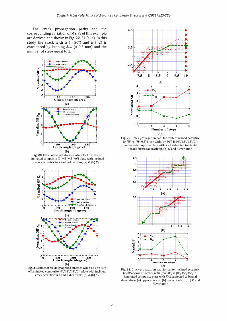
The crack propagation paths and the corresponding variation of MSIFs of this example are derived and shown in Fig. 22-24 (a- c). In this study the crack with α (= 50°) and K (=2) is considered by keeping Δincr (= 0.5 mm) and the number of steps equal to 5.
(a)
(b)
Fig. 20. Effect of biaxial stresses when K=1 on SIFs of laminated composite [0°/45°/45°/0°] plate with inclined
crack eccentric in X and Y-directions, (a) KI (b) KII
(a)
(b)
Fig. 21. Effect of biaxially applied stresses when K=2 on SIFs of laminated composite [0°/45°/45°/0°] plate with inclined
crack eccentric in X and Y-directions, (a) KI (b) KII
(a)
(b)
Fig. 22. Crack propagation path for center inclined eccentric (ex/W =ey/H= 0.5) crack with (α= 50°) in [0°/45°/45°/0°] laminated composite plate with K =2 subjected to biaxial
tensile stress (a) crack tip, (b) KI and KII variation
(a)
(b)
(c)
Fig. 23. Crack propagation path for center inclined eccentric (ex/W=ey/H= 0.5) crack with (α = 50°) in [0°/45°/45°/0°] laminated composite plate with K=2 subjected to biaxial
shear stress (a) upper crack tip (b) lower crack tip, (c) KI and KII variation
0 50 100 150-3
-2
-1
0
1
2
3
4
Crack angle (degree)
Nor
mal
ized
SIF
KI
Tensile stress
Shear stress
Combined stress
0 50 100 150-2
-1
0
1
2
Crack angle (degree)
Nor
mal
ized
SIF
KII
Tensile stress
Shear stress
Combined stress
0 50 100 150-4
-2
0
2
4
6
Crack angle (degree)
Nor
mal
ized
SIF
KI
Tensile stress
Shear stress
Combined stress
0 50 100 150-3
-2
-1
0
1
2
Crack angle (degree)
Nor
mal
ized
SIF
KII
Tensile stress
Shear stress
Combined
stress
7.5 8 8.5 9 9.5 10
2.5
3
3.5
4
4.5
1 2 3 4 5-1
0
1
2
3
4
Number of stepsN
orm
ali
zed
SIF
KI
KII
7 7.5 8 8.5 9 9.5
2.5
3
3.5
4
4.5
7 7.5 8
2.5
1 2 3 4 5-3
-2
-1
0
1
2
3
Number of steps
Norm
alize
d SI
F
KI
KII
Shailesh & Lal / Mechanics of Advanced Composite Structures 8 (2021) 213-234
231
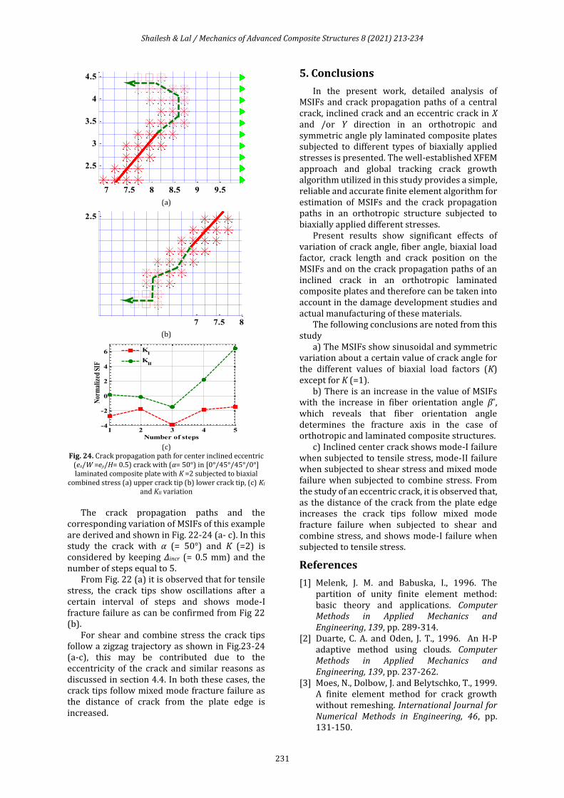
(a)
(b)
(c)
Fig. 24. Crack propagation path for center inclined eccentric (ex/W =ey/H= 0.5) crack with (α= 50°) in [0°/45°/45°/0°] laminated composite plate with K =2 subjected to biaxial
combined stress (a) upper crack tip (b) lower crack tip, (c) KI and KII variation
The crack propagation paths and the
corresponding variation of MSIFs of this example are derived and shown in Fig. 22-24 (a- c). In this study the crack with α (= 50°) and K (=2) is considered by keeping Δincr (= 0.5 mm) and the number of steps equal to 5.
From Fig. 22 (a) it is observed that for tensile stress, the crack tips show oscillations after a certain interval of steps and shows mode-I fracture failure as can be confirmed from Fig 22 (b).
For shear and combine stress the crack tips follow a zigzag trajectory as shown in Fig.23-24 (a-c), this may be contributed due to the eccentricity of the crack and similar reasons as discussed in section 4.4. In both these cases, the crack tips follow mixed mode fracture failure as the distance of crack from the plate edge is increased.
5. Conclusions
In the present work, detailed analysis of MSIFs and crack propagation paths of a central crack, inclined crack and an eccentric crack in X and /or Y direction in an orthotropic and symmetric angle ply laminated composite plates subjected to different types of biaxially applied stresses is presented. The well-established XFEM approach and global tracking crack growth algorithm utilized in this study provides a simple, reliable and accurate finite element algorithm for estimation of MSIFs and the crack propagation paths in an orthotropic structure subjected to biaxially applied different stresses.
Present results show significant effects of variation of crack angle, fiber angle, biaxial load factor, crack length and crack position on the MSIFs and on the crack propagation paths of an inclined crack in an orthotropic laminated composite plates and therefore can be taken into account in the damage development studies and actual manufacturing of these materials.
The following conclusions are noted from this study
a) The MSIFs show sinusoidal and symmetric variation about a certain value of crack angle for the different values of biaxial load factors (K) except for K (=1).
b) There is an increase in the value of MSIFs with the increase in fiber orientation angle β˚, which reveals that fiber orientation angle determines the fracture axis in the case of orthotropic and laminated composite structures.
c) Inclined center crack shows mode-I failure when subjected to tensile stress, mode-II failure when subjected to shear stress and mixed mode failure when subjected to combine stress. From the study of an eccentric crack, it is observed that, as the distance of the crack from the plate edge increases the crack tips follow mixed mode fracture failure when subjected to shear and combine stress, and shows mode-I failure when subjected to tensile stress.
References
[1] Melenk, J. M. and Babuska, I., 1996. The partition of unity finite element method: basic theory and applications. Computer Methods in Applied Mechanics and Engineering, 139, pp. 289-314.
[2] Duarte, C. A. and Oden, J. T., 1996. An H-P adaptive method using clouds. Computer Methods in Applied Mechanics and Engineering, 139, pp. 237-262.
[3] Moes, N., Dolbow, J. and Belytschko, T., 1999. A finite element method for crack growth without remeshing. International Journal for Numerical Methods in Engineering, 46, pp. 131-150.
7 7.5 8 8.5 9 9.5
2.5
3
3.5
4
4.5
7 7.5 8
2.5
1 2 3 4 5-4
-2
0
2
4
6
Number of steps
Nor
mal
ized
SIF
KI
KII
Shailesh & Lal / Mechanics of Advanced Composite Structures 8 (2021) 213-234
232
[4] Bellec, J. and Dolbow, J. E., 2003. A note on enrichment functions for modelling crack nucleation. Communications in Numerical Methods in Engineering, 19, pp. 921-932.
[5] Belytschko, T., Chen, H., Xu, J. and Zi, G., 2003. Dynamic crack propagation based on loss of hyperbolicity and a new discontinuous enrichment. International Journal for Numerical Methods in Engineering, 58, pp. 1873-1905.
[6] Sukumar, N. and Prevost, J. H., 2003. Modelling quasi-static crack growth with the extended finite element method, part –I, computer implementation. International Journal of Solids and Structures, 40, pp. 7513-7537.
[7] Belytschko, T., Gracie, R. and Ventura, G., 2009. A review of extended/generalized finite element methods for material modelling. International Journal of Fracture, 131, pp. 124-129.
[8] Sukumar, N., Dolbow, J., Devan, A., Yvonnet, J., Chinesta, F., Ryckelynck, D., Lorong, P., Alfaro, I., Martínez, M. A., Cueto, E. and Doblaré, M., 2005. Meshless methods and partition of unity finite elements. International Journal of Forming Processes, 8, pp. 409-427.
[9] Belytschko, T. and Gracie, R., 2007. On X-FEM applications to dislocations and interfaces. International Journal of Plasticity, 23, pp. 1721-1738.
[10] Tabarraei, A. and Sukumar, N., 2007. Extended finite element method on polygonal and quadtree meshes. Computer Methods in Applied Mechanics and Engineering, 197, 425-438.
[11] Richardson, C. L., Hegemann, J., Sifakis, E., Hellrung, J. and Teran, J. M., 2009. An X-FEM method for modelling geometrically elaborate crack propagation in brittle materials. International Journal for Numerical Methods in Engineering, 1, pp. 1042-1065.
[12] Liang, R. Z., Rui, Z. C., Liang, Z. Y. and Bo. Z. H., 2010. M-Integral for stress intensity factor based on X-FEM. Proceedings ISECS’10, Guangzhou, P. R. China. Numerical Methods in Engineering, 1, pp. 1042-1065.
[13] Mousavi, S. E. and Sukumar, N., 2010. Generalized Gaussian quadrature rules for discontinuities and crack singularities in the extended finite element method. Computer Methods in Applied Mechanics and Engineering, 199, pp. 3237-3249.
[14] Giner, E., Sukumar, N., Tarancon, J. E. and Fuenmayor, F. J., 2009. An ABAQUS implementation of the extended finite element method. Engineering Fracture Mechanics, 76, pp. 347-368.
[15] Chatzi, E. N., Hiriyur, B., Waisman, H. and Smyth, A. W., 2011. Experimental application
and enhancement of the X-FEM–GA algorithm for the detection of flaws in structures. Computers and Structures, 89, pp. 556-570.
[16] Abdelaziz, Y. and Hamouine, A., 2008. A survey of the extended finite element. Computers and Structures, 86, pp.1141-1151.
[17] Hattori, G., Rojas-Diaz, R., Saez, A., Sukumar, N. and Garcia, S. F., 2012. New anisotropic crack-tip enrichment functions for the extended finite element method. Computational Mechanics, 50, pp. 591-601.
[18] Asadpoure, A., Mohammadi, S. and Vafai, A., 2006. Modelling crack in orthotropic media using a coupled finite element and partition of unity methods. Finite Elements in Analysis and Design, 42, pp. 165-175.
[19] Asadpoure, A., Mohammadi, S. and Vafai, A., 2006. Crack analysis in orthotropic media using the extended finite element method. Thin-Walled Structures, 44, pp. 1031-1038.
[20] Asadpoure, A. and Mohammadi, S., 2007. Developing new enrichment functions for crack simulation in orthotropic media by the extended finite element method. International Journal for Numerical Methods in Engineering, 69, pp. 2150-2172.
[21] Ebrahimi, S. H., Mohammadi, S. and Asadpoure, A., 2008. An extended finite element (X-FEM) approach for crack analysis in composite media. International Journal of Civil Engineering, 6, pp. 198-207.
[22] Ghorashi, S. S., Mohammadi, S. and Yazdi, S. R. S., 2011. Orthotropic enriched element free Galerkin method for fracture analysis of composites. Engineering Fracture Mechanics, 78, pp. 1906-1927.
[23] Bhardwaj, G., Singh, I.V., Mishra, B.K., Bui, T.Q., 2015. Numerical simulation of functionally graded cracked plates using NURBS based XIGA under different loads and boundary conditions. Composite Structures, 126, pp. 347-359.
[24] Chen, X., Gu, J., Yu, T., Qiu, L., Bui, T. Q., 2019. Numerical simulation of arbitrary holes in orthotropic media by an efficient Computational method based on adaptive XIGA. Composite Structures, 229, 111387.
[25] Gu, J., Yu, T., Lich, L. V., Tanaka, S., Qiu, L., Bui, T. Q., 2019. Adaptive orthotropic XIGA for fracture analysis of composites. Composites Part- B, 176, 107259.
[26] Gu, J., Yu, T., Lich, L. V., Tanaka, S., Yuan, H., Bui, T. Q., 2020. Crack growth adaptive XIGA simulation in isotropic and orthotropic materials. Computer Methods in Applied Mechanics and Engineering, 365, 113016.
[27] Yu, T., Yuan, H., Gu, J., Tanaka, S., Bui, T. Q., 2020. Error-controlled adaptive LR B-splines XIGA for assessment of fracture
Shailesh & Lal / Mechanics of Advanced Composite Structures 8 (2021) 213-234
233
parameters in through-cracked Mindlin- Reissner plates. Engineering Fracture Mechanics, 229, 106964.
[28] Fang, W., Wu, J., Yu, T., Nguyen, T. T., Bui, T. Q., 2019. Simulation of cohesive crack growth by a variable-node XFEM. Frontiers of Structural and Civil Engineering, 14, pp. 215-228.
[29] Liu, P., Bui, T.Q., Zhu, D., Yu, T.T., Wang, J.W., Yin, S.H., Hirose, S., 2015. Buckling failure analysis of cracked functionally graded plates by a stabilized discrete shear gap extended 3-node triangular plate element. Composites Part- B, 77, pp. 79-193.
[30] Wang, Z., Yu, T., Bui, T. Q., Tanaka, Zhang, C., Hirose, S., Jose, L., Sosa, C., 2016. 3-D Local Mesh Refinement XFEM with Variable-Node Hexahedron Elements for Extraction of Stress Intensity Factors of Straight and Curved Planar Cracks. Computer Methods in Applied Mechanics and Engineering, 313, pp. 375-405.
[31] Wang, Z., Yu, T., Bui, T. Q., Trinh, N. A., Luong, N. T. H., Duc, N. D., Doan, D. H., 2016. Numerical modeling of 3-D inclusions and voids by a novel adaptive XFEM. Advances in Engineering Software, 102, pp. 105-122.
[32] Yin, S., Yu, T., Bui, T. Q., Liu, P., Hirose, S., 2016. Buckling and vibration extended isogeometric analysis of imperfect graded Reissner-Mindlin plates with internal defects using NURBS and level sets. Computers and Structures, 177, pp. 23-38.
[33] Ma, C., Yu, T., Lich, L. V., Bui, T. Q., 2017. An effective computational approach based on XFEM and a novel three-step detection algorithm for multiple complex flaw clusters. Computers and Structures, 193, pp. 207-225.
[34] Yu, T., Bui, T. Q., 2018. Numerical simulation of 2-D weak and strong discontinuities by a novel approach based on XFEM with local mesh refinement. Computers and Structures, 196, pp. 112-133.
[35] Bui, T. Q., Nguyen, N. T., Lich, L. V., Nguyen, M. N., Truong, T. T., 2018. Analysis of transient dynamic fracture parameters of cracked functionally graded composites by improved meshfree methods. Theoretical and Applied Fracture Mechanics, 96, pp. 642-657.
[36] Ding, J., Yu, T., Bui, T. Q., 2020. Modeling strong/weak discontinuities by local mesh refinement variable node XFEM with object-oriented implementation. Theoretical and Applied Fracture Mechanics, 106, 102434, pp.1-19.
[37] Ding, J., Yu, T., Yang, Y., Bui, T. Q., 2020. An efficient variable-node XFEM for modeling multiple crack growth: A Matlab object-oriented implementation. Advances in Engineering Software, 140, 102750.
[38] Pathak, H., Singh, A., Singh, I. V., 2013. Fatigue crack growth simulations of 3-D problems using XFEM. International Journal of Mechanical Sciences, 76, pp. 112-131.
[39] Pathak, H., Singh, A., Singh, I. V., Yadav, S. K., 2015. Fatigue crack growth simulations of 3-D linear elastic cracks under thermal load by XFEM. Frontiers of Structural and Civil Engineering, 9(4), pp. 359-382.
[40] Kumar, M., Singh, I.V., Mishra, B.K., 2019. Fatigue crack growth simulations of plastically graded materials using XFEM and J-integral decomposition approach. Engineering Fracture Mechanics, 216, 106470.
[41] Pathak, H., 2018. Crack interaction study in functionally graded materials (FGMs) using XFEM under thermal and mechanical loading environment. Mechanics of Advanced Materials and Structures, 27 (11), pp. 903- 926.
[42] Mishra, R., Burela, R. G., Pathak, H., 2018. Crack interaction study in piezoelectric materials under thermo-electro-mechanical loading environment. International Journal of Mechanics and Materials in Design, 15, pp. 379-412.
[43] Patil, R.U., Mishra, B.K., Singh, I.V., 2019. A multiscale framework based on phase field method and XFEM to simulate fracture in highly heterogeneous materials. Theoretical and Applied Fracture Mechanics, 100, pp. 390-415.
[44] Bansal, M., Singh, I.V., Mishra, B.K., Bordas, S.P.A., 2019. A parallel and efficient multi-split XFEM for 3-D analysis of heterogeneous materials. Computer Methods in Applied Mechanics and Engineering, 347, pp. 365-401.
[45] Kumar, S., Singh, I. V., Mishra, B.K., Sharma, K., Khan, I. A., 2019. A homogenized multigrid XFEM to predict the crack growth behavior of ductile material in the presence of microstructural defects. Engineering Fracture Mechanics, 205, pp. 577-602.
[46] Jones, D. L., Poulose, P. K. and Liebowitz, H., 1986. The effects of biaxial loading on the fracture characteristics of several engineering materials. Engineering Fracture Mechanics, 24 (2), pp. 187-205.
[47] Kfouri, P. and Miller, K. J., 1977.The effect of load biaxiality on the fracture toughness parameters J and GA. Fracture Proc. tCF4, Waterloo, Canada, University of Waterloo Press, 3, pp. 241-245.
[48] Lee, J. D. and Liebowitz, H., 1977. The nonlinear and biaxial effects on energy release rate, J-integral, and stress intensity factor. Engineering Fracture Mechanics, 9, pp. 765-779.
Shailesh & Lal / Mechanics of Advanced Composite Structures 8 (2021) 213-234
234
[49] Liebowitz, H., Lee, J. D. and Efus, J., 1978. Biaxial load effects in fracture mechanics. Engineering Fracture Mechanics, 10, pp. 315-335.
[50] Oladimeji, M. K., 1981. Cracks emanating from a circular hole under biaxial load. Engineering Fracture Mechanics, 15, pp. 391-405.
[51] Theocaris, I. S. and Papadopoulos, G. A., 1985. Crack-propagation trajectories under biaxial loading based on fracture criteria. Journal of the Franklin Institute, pp. 16-32.
[52] Lim, W. K., Choi, S.Y. and Sankar, B. V., 2001. Biaxial load effects on crack extension in anisotropic solids. Engineering Fracture Mechanics, 68, pp. 403-416.
[53] Carloni, C., Piva, A. and Viola, E., 2003. An alternative complex variable formulation for an inclined crack in an orthotropic medium. Engineering Fracture Mechanics, 70, pp. 2033-2058.
[54] Nobile, L. and Carloni, C., 2005. Fracture analysis for orthotropic cracked plates. Composite Structures, 68, pp. 285-293.
[55] Nobile, L., Piva, A. and Viola, E., 2004. On the inclined crack problem in an orthotropic medium under biaxial loading. Engineering Fracture Mechanics, 71, pp. 529-546.
[56] Wang, J. G., Ju, D. Y., Sun, M. J. and Li, S. L., 2011.A new analytical method for stress intensity factors based on IN-SITU measurement of crack deformation under biaxial tension. Materials and Design, 32, pp. 664-670.
[57] Mostafavi, M., Smith, D. J. and Pavier, M. J., 2011. Fracture of aluminum alloy 2024 under biaxial and triaxial loading. Engineering Fracture Mechanics, 78, pp. 1705-1716.
[58] Goldstein, R. V. and Shifrin, E. I., 2012. Conditions for mode I crack deviation in orthotropic plane subjected to biaxial loading. International Journal of Engineering Science, 61, pp. 36-47.
[59] Meek, C. and Ainsworth, R. A., 2015. The effects of load biaxiality and plate length on the limit load of a center-cracked plate. Engineering Fracture Mechanics, 147, pp. 306-317.
[60] Mohammadi, S., 2008. Extended finite element method for fracture analysis of structures. Blackwell, Oxford.
[61] Mohammadi, S., 2012. XFEM Fracture Analysis of Composites. A John Wiley & Sons, Ltd. Publication, United Kingdom.
[62] Lekhnitskii, S. G., 1963. Theory of an Anisotropic Elastic Body. San Francisco: Holden-Day.
[63] Sad, M. H., 2005. Elasticity: theory, applications, and numeric. Elsevier.
[64] Sih, G. C., Paris, P. C. and Irwin, G. R., 1965. On cracks in rectilinearly anisotropic bodies. International Journal of Fracture Mechanics, 1, pp. 189-203.
[65] Wang, S. S., Yau, J. F. and Corten, H. T., 1980. A mixed mode crack analysis of rectilinear anisotropic solids using conservation laws of elasticity. International Journal of Fracture, 16, pp. 247-259.
[66] Sih, G., 1974. Strain energy density factor applied to mixed mode crack problem. International Journal of Fracture, 10, pp. 305-321.
[67] Nuismer, R., 1975. An energy release rate criterion for mixed fracture. International Journal of Fracture, 11, pp. 245-250.
[68] Erdogan, F. and Sih, G., 1963. On the crack extension in plates under plane loading and transverse shear. Journal of Basic Engineering, 85, pp. 519-527.
[69] Oliver, J., Huespe, A., Samaniego, E. and Chaves, E., 2004. Continuum Approach to the Numerical Simulation of Material Failure in Concrete. International Journal for Numerical and Analytical Methods in Geomechnics, 28, pp. 609-632.
[70] Oliver, J., Huespe, A., Samaniego, E. and Chaves, W. V., 2002. On strategies for tracking strong discontinuities in computational failure mechanics. Fifth World Congress on Computational Mechanics (WCCM -V).
[71] Dumstorff, P. and Meschke, G., 2007. Crack propagation criteria in the framework of XFEM based structural analyses. International Journal for Numerical and Analytical Methods in Geomechnics, 31, pp. 239-259.
[72] Areias, P. M. and Belytscchko, T., 2005. Analysis of three-dimensional crack initiation and propagation using the extended finite element method. International Journal of Numerical Methods in Engineering, 63, pp. 760-788.
[73] Xie, M. and Gerstle, W. H., 1995. Energy-based cohesive crack propagation modelling. Journal of Engineering Mechanics, 121(12), pp. 1349-1358.