Embed Size (px)
Citation preview
XFEL THIRD HARMONIC SUPERCONDUCTING CAVITY PROTOTYPES: FABRICATION AND PROCESSING EXPERIENCE
P. Pierini , A. Bosotti, P. Michelato, L. Monaco, R. Paparella, D. Sertore, INFN Milano - LASA, 20090 Segrate, MI, Italy
E. Vogel, DESY, 22603 Hamburg, Germany.
Abstract Three superconducting 3.9 GHz cavity prototypes have
been fabricated for the XFEL linac injector, with minor modifications to the RF structures built at FNAL for the FLASH linac. This paper describes the production procedures and the RF preparation experience, the chemical processing and the plans for the vertical test at INFN Milano for the characterization of the structure.
INTRODUCTION The European XFEL linac injector includes a third
harmonic (3.9 GHz) accelerating section in order to generate the high quality electron beam required for the short wavelength FEL operation. The third harmonic section is required for the linearization of the beam phase space before the longitudinal bunch compression performed to increase the peak current for lasing [1].
A short module of four 3.9 GHz cavities, ACC39, designed and contributed by FNAL to DESY, will be put into operation during 2010 in the FLASH FEL facility as a proof of principle of the concept. A number of cavities have been successfully fabricated and tested at FNAL, exceeding the required performances [2].
The cavity design for the XFEL third harmonic section has been derived from the FNAL design, with the minimal modifications described in ref. [3] to adapt to the slightly different XFEL modules environment.
The main components of the XFEL third harmonic system will be procured jointly by INFN and DESY as in-kind contributions to the European XFEL Project.
PRODUCTION OF CAVITY PROTOTYPES In order to prepare for the realization of the European
XFEL third harmonic system, a small preseries of three cavities has been tendered by DESY (under the supervision of INFN personnel) to one of the companies qualified for the XFEL cavity production. The vendor is responsible for the fabrication and surface processing, up to the final assembly for the vertical tests at INFN.
Cavity Mockups For the development of the initial fabrication
procedures and to assist in the commissioning of the necessary tooling for these new structures at the company (for fabrication, welding, field flatness tuning and surface processing) first a simplified copper RF mockup (with no auxiliary ports) and later a complete Niobium mockup (using non RF-grade material, from discarded sheets after scanning) have been produced. Their RF properties have been extensively characterized at warm.
The mockups have been used to determine the frequency sensitivity parameters (for trimming and tuning) and the weld shrinkages necessary to define the structure fabrication procedure in order to meet the correct frequency and length of the final structure. Furthermore, they proved useful in the development of all software tools for the RF measurements and field flatness adjustment procedures.
Figure 1: Components of the Nb mockup during intermediate fabrication steps.
Cavity Prototypes Three structures have then been fabricated on the basis
of the experience gathered from the mockups, after some further small adjustment performed during the analysis of all produced subcomponents (half-cell, dumb-bells) [4]. After fabrication, it was decided to perform a frequency adjustment and field flatness tuning prior to the BCP etching of the cavity. During this operation the cavity length was adjusted within a mm from its nominal value, and the field flatness raised to a value above 95%. In order to reach the correct length the cavities have been tuned to a frequency slightly higher (by 3 MHz) than originally estimated by our original assumptions. The further frequency adjustment to recover this offset will be therefore performed by correspondingly increasing the etch removal by approximately 100 μm.
Figure 2: The field flatness tuning machine.
THPPO092 Proceedings of SRF2009, Berlin, Germany
09 Cavity preparation and production
844
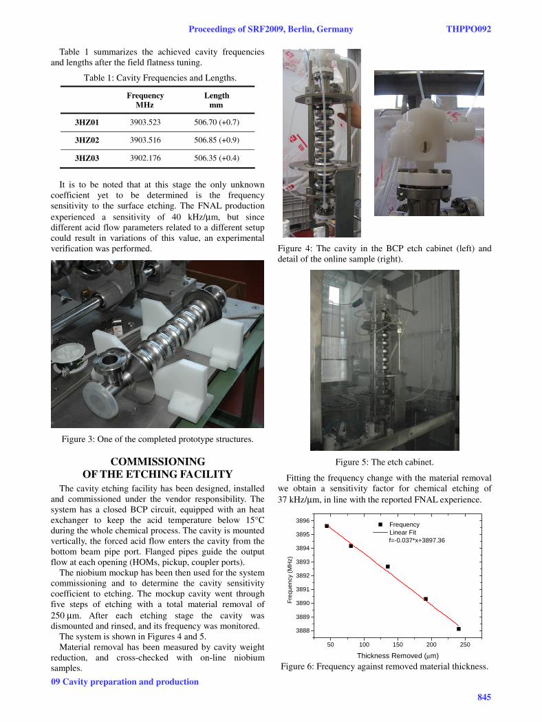
Table 1 summarizes the achieved cavity frequencies and lengths after the field flatness tuning.
Table 1: Cavity Frequencies and Lengths.
Frequency MHz
Length mm
3HZ01 3903.523 506.70 (+0.7)
3HZ02 3903.516 506.85 (+0.9)
3HZ03 3902.176 506.35 (+0.4)
It is to be noted that at this stage the only unknown
coefficient yet to be determined is the frequency sensitivity to the surface etching. The FNAL production experienced a sensitivity of 40 kHz/μm, but since different acid flow parameters related to a different setup could result in variations of this value, an experimental verification was performed.
Figure 3: One of the completed prototype structures.
COMMISSIONING OF THE ETCHING FACILITY
The cavity etching facility has been designed, installed and commissioned under the vendor responsibility. The system has a closed BCP circuit, equipped with an heat exchanger to keep the acid temperature below 15°C during the whole chemical process. The cavity is mounted vertically, the forced acid flow enters the cavity from the bottom beam pipe port. Flanged pipes guide the output flow at each opening (HOMs, pickup, coupler ports).
The niobium mockup has been then used for the system commissioning and to determine the cavity sensitivity coefficient to etching. The mockup cavity went through five steps of etching with a total material removal of 250 μm. After each etching stage the cavity was dismounted and rinsed, and its frequency was monitored.
The system is shown in Figures 4 and 5. Material removal has been measured by cavity weight
reduction, and cross-checked with on-line niobium samples.
Figure 4: The cavity in the BCP etch cabinet (left) and detail of the online sample (right).
Figure 5: The etch cabinet.
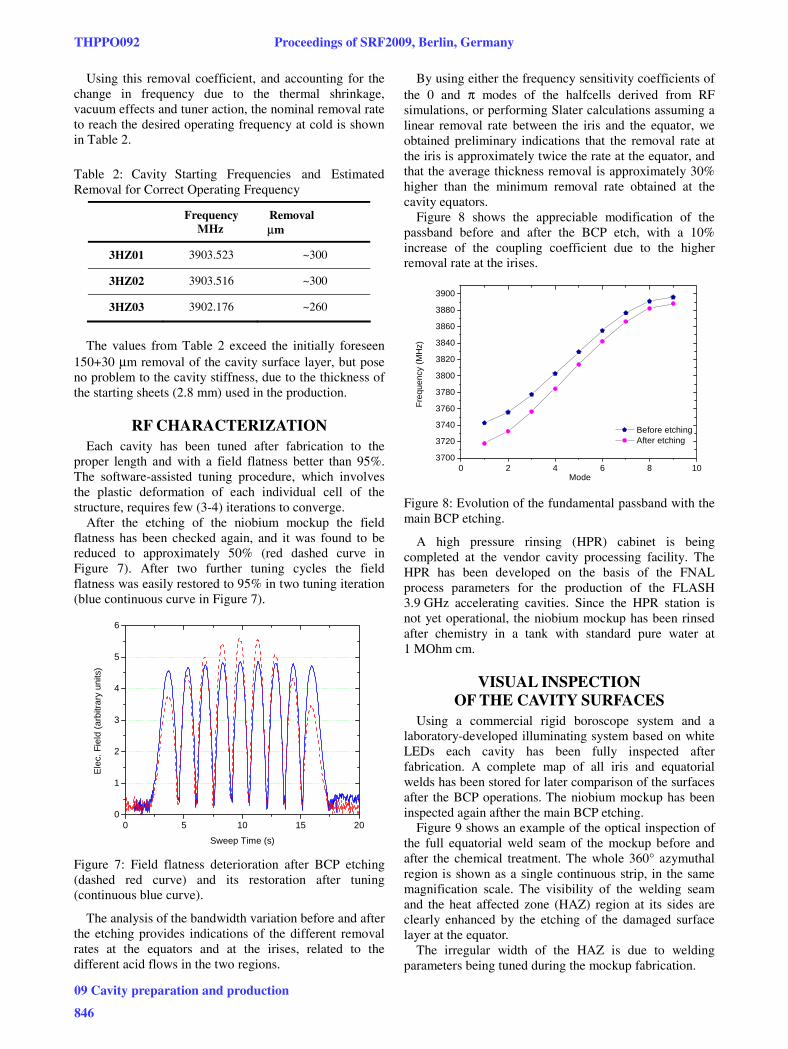
Fitting the frequency change with the material removal we obtain a sensitivity factor for chemical etching of 37 kHz/μm, in line with the reported FNAL experience.
50 100 150 200 250
3888
3889
3890
3891
3892
3893
3894
3895
3896
Frequency Linear Fit
f=-0.037*x+3897.36
Fre
quen
cy (
MH
z)
Thickness Removed (μm)
Figure 6: Frequency against removed material thickness.
Proceedings of SRF2009, Berlin, Germany THPPO092
09 Cavity preparation and production
845
Using this removal coefficient, and accounting for the change in frequency due to the thermal shrinkage, vacuum effects and tuner action, the nominal removal rate to reach the desired operating frequency at cold is shown in Table 2.
Table 2: Cavity Starting Frequencies and Estimated emoval for orrect perating Frequency
Frequency MHz
Removal μm
3HZ01 3903.523 ~300
3HZ02 3903.516 ~300
3HZ03 3902.176 ~260
The values from Table 2 exceed the initially foreseen
150+30 μm removal of the cavity surface layer, but pose no problem to the cavity stiffness, due to the thickness of the starting sheets (2.8 mm) used in the production.
RF CHARACTERIZATION Each cavity has been tuned after fabrication to the
proper length and with a field flatness better than 95%. The software-assisted tuning procedure, which involves the plastic deformation of each individual cell of the structure, requires few (3-4) iterations to converge.
After the etching of the niobium mockup the field flatness has been checked again, and it was found to be reduced to approximately 50% (red dashed curve in Figure 7). After two further tuning cycles the field flatness was easily restored to 95% in two tuning iteration (blue continuous curve in Figure 7).
0 5 10 15 200
1
2
3
4
5
6
Ele
c. F
ield
(ar
bitr
ary
units
)
Sweep Time (s)
Figure 7: Field flatness deterioration after BCP etching (dashed red curve) and its restoration after tuning (continuous blue curve).
The analysis of the bandwidth variation before and after the etching provides indications of the different removal rates at the equators and at the irises, related to the different acid flows in the two regions.
By using either the frequency sensitivity coefficients of the 0 and π modes of the halfcells derived from RF simulations, or performing Slater calculations assuming a linear removal rate between the iris and the equator, we obtained preliminary indications that the removal rate at the iris is approximately twice the rate at the equator, and that the average thickness removal is approximately 30% higher than the minimum removal rate obtained at the cavity equators.
Figure 8 shows the appreciable modification of the passband before and after the BCP etch, with a 10% increase of the coupling coefficient due to the higher removal rate at the irises.
0 2 4 6 8 103700
3720
3740
3760
3780
3800
3820
3840
3860
3880
3900
Before etching After etching
Fre
quen
cy (
MH
z)
Mode
Figure 8: Evolution of the fundamental passband with the main BCP etching.
A high pressure rinsing (HPR) cabinet is being completed at the vendor cavity processing facility. The HPR has been developed on the basis of the FNAL process parameters for the production of the FLASH 3.9 GHz accelerating cavities. Since the HPR station is not yet operational, the niobium mockup has been rinsed after chemistry in a tank with standard pure water at 1 MOhm cm.
VISUAL INSPECTION OF THE CAVITY SURFACES
Using a commercial rigid boroscope system and a laboratory-developed illuminating system based on white LEDs each cavity has been fully inspected after fabrication. A complete map of all iris and equatorial welds has been stored for later comparison of the surfaces after the BCP operations. The niobium mockup has been inspected again afther the main BCP etching.
Figure 9 shows an example of the optical inspection of the full equatorial weld seam of the mockup before and after the chemical treatment. The whole 360° azymuthal region is shown as a single continuous strip, in the same magnification scale. The visibility of the welding seam and the heat affected zone (HAZ) region at its sides are clearly enhanced by the etching of the damaged surface layer at the equator.
The irregular width of the HAZ is due to welding parameters being tuned during the mockup fabrication.
R C O
THPPO092 Proceedings of SRF2009, Berlin, Germany
09 Cavity preparation and production
846
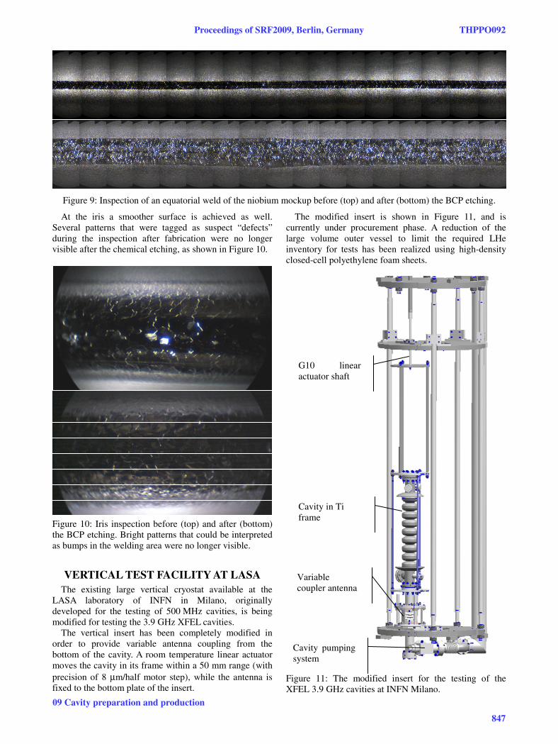
Figure 9: Inspection of an equatorial weld of the niobium mockup before (top) and after (bottom) the BCP etching.
At the iris a smoother surface is achieved as well. Several patterns that were tagged as suspect “defects” during the inspection after fabrication were no longer visible after the chemical etching, as shown in Figure 10.
Figure 10: Iris inspection before (top) and after (bottom) the BCP etching. Bright patterns that could be interpreted as bumps in the welding area were no longer visible.
VERTICAL TEST FACILITY AT LASA The existing large vertical cryostat available at the
LASA laboratory of INFN in Milano, originally developed for the testing of 500 MHz cavities, is being modified for testing the 3.9 GHz XFEL cavities.
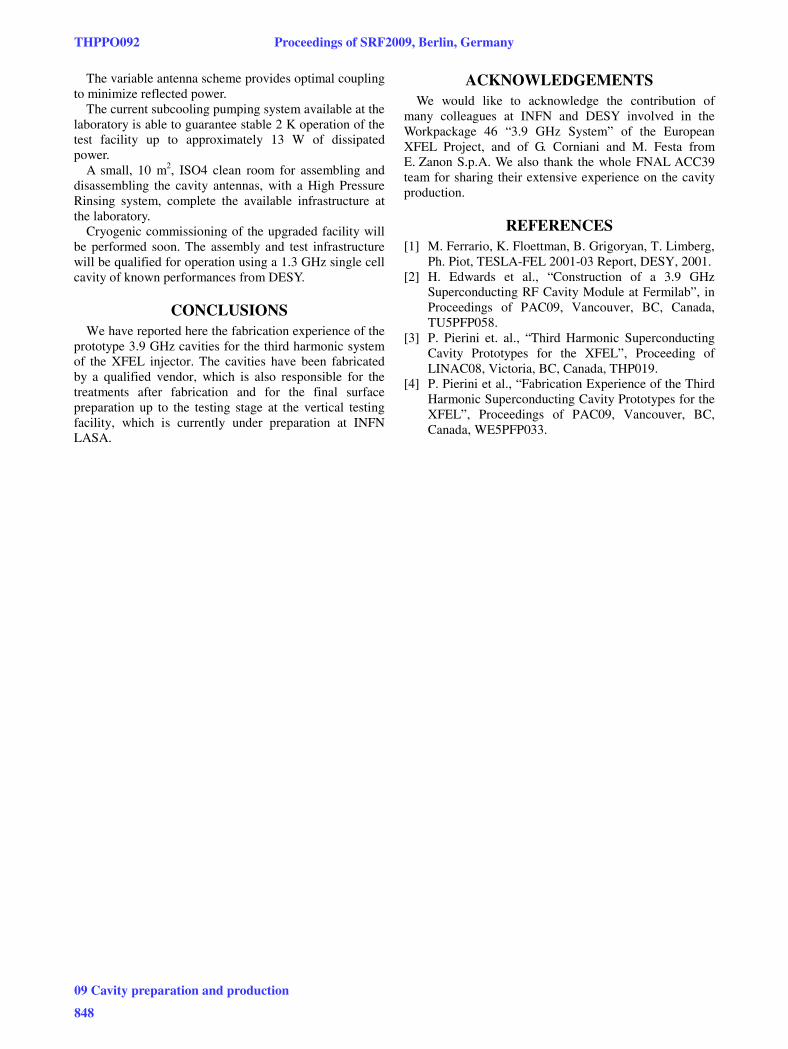
The vertical insert has been completely modified in order to provide variable antenna coupling from the bottom of the cavity. A room temperature linear actuator moves the cavity in its frame within a 50 mm range (with precision of 8 μm/half motor step), while the antenna is fixed to the bottom plate of the insert.
The modified insert is shown in Figure 11, and is currently under procurement phase. A reduction of the large volume outer vessel to limit the required LHe inventory for tests has been realized using high-density closed-cell polyethylene foam sheets.
Figure 11: The modified insert for the testing of the XFEL 3.9 GHz cavities at INFN Milano.
Variable coupler antenna
Cavity in Ti frame
G10 linear actuator shaft
Cavity pumping system
Proceedings of SRF2009, Berlin, Germany THPPO092
09 Cavity preparation and production
847
The variable antenna scheme provides optimal coupling to minimize reflected power.
The current subcooling pumping system available at the laboratory is able to guarantee stable 2 K operation of the test facility up to approximately 13 W of dissipated power.
A small, 10 m2, ISO4 clean room for assembling and disassembling the cavity antennas, with a High Pressure Rinsing system, complete the available infrastructure at the laboratory.
Cryogenic commissioning of the upgraded facility will be performed soon. The assembly and test infrastructure will be qualified for operation using a 1.3 GHz single cell cavity of known performances from DESY.
CONCLUSIONS We have reported here the fabrication experience of the
prototype 3.9 GHz cavities for the third harmonic system of the XFEL injector. The cavities have been fabricated by a qualified vendor, which is also responsible for the treatments after fabrication and for the final surface preparation up to the testing stage at the vertical testing facility, which is currently under preparation at INFN LASA.
ACKNOWLEDGEMENTS We would like to acknowledge the contribution of
many colleagues at INFN and DESY involved in the Workpackage 46 “3.9 GHz System” of the European XFEL Project, and of G. Corniani and M. Festa from E. Zanon S.p.A. We also thank the whole FNAL ACC39 team for sharing their extensive experience on the cavity production.
REFERENCES [1] M. Ferrario, K. Floettman, B. Grigoryan, T. Limberg,
Ph. Piot, TESLA-FEL 2001-03 Report, DESY, 2001. [2] H. Edwards et al., “Construction of a 3.9 GHz
Superconducting RF Cavity Module at Fermilab”, in Proceedings of PAC09, Vancouver, BC, Canada, TU5PFP058.
[3] P. Pierini et. al., “Third Harmonic Superconducting Cavity Prototypes for the XFEL”, Proceeding of LINAC08, Victoria, BC, Canada, THP019.
[4] P. Pierini et al., “Fabrication Experience of the Third Harmonic Superconducting Cavity Prototypes for the XFEL”, Proceedings of PAC09, Vancouver, BC, Canada, WE5PFP033.
THPPO092 Proceedings of SRF2009, Berlin, Germany
09 Cavity preparation and production
848


![Overview of E-XFEL Standard Electron Beam … Cavity BPM The re-entrant cavity BPM has the potential of better resolution compared to the standard button type [7]. From the mechanical](https://img.pdfslide.us/doc/110x75/5af711c37f8b9a8d1c8fbcb1/overview-of-e-xfel-standard-electron-beam-cavity-bpm-the-re-entrant-cavity-bpm.jpg)