Embed Size (px)
Citation preview
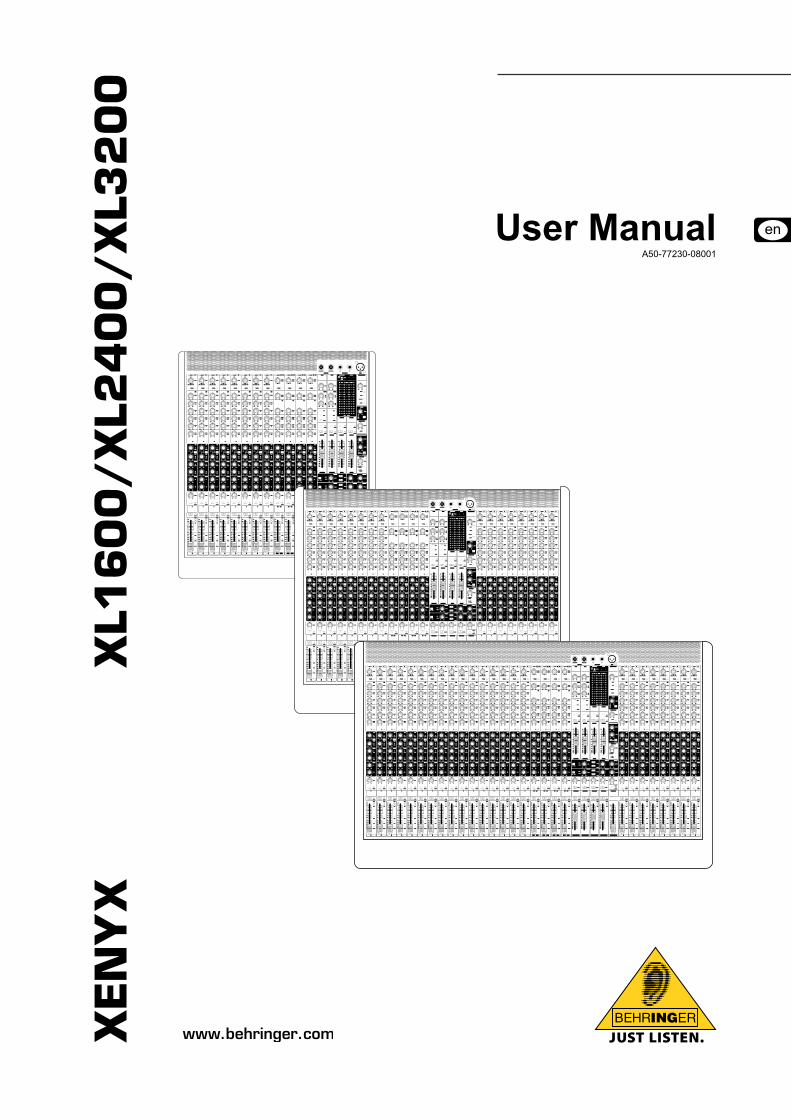
XE
NY
X
XL1
60
0/
XL2
40
0/
XL3
20
0
User ManualA50-77230-08001
XENYX XL1600/XL2400/XL3200
2
Important Safety Instructions
This symbol, wherever it appears, alerts you to the
* presence of uninsulated dangerous voltage inside the enclosure - voltage that may be suffi cient to constitute a risk of shock.
This symbol, wherever it appears, alerts you to important
! operating and maintenance instructions in the accom-panying literature. Please read the manual.
CautionTo reduce the risk of electric shock, do not remove the +top cover (or the rear section). No user serviceable parts inside. Refer servicing to qualifi ed personnel.
To reduce the risk of fi re or electric shock, do not expose +this appliance to rain and moisture. The apparatus shall not be exposed to dripping or splashing liquids and no objects fi lled with liquids, such as vases, shall be placed on the apparatus.
These service instructions are for use by qualifi ed ser- +vice personnel only. To reduce the risk of electric shock do not perform any servicing other than that contained in the operation instructions.Repairs have to be performed by qualifi ed service personnel.
Read these instructions.1) Keep these instructions.2) Heed all warnings.3) Follow all instructions.4) Do not use this apparatus near water.5) Clean only with dry cloth.6) Do not block any ventilation openings. Install in accor-7) dance with the manufacturer’s instructions.Do not install near any heat sources such as radiators, 8) heat registers, stoves, or other apparatus (including amplifi ers) that produce heat.Do not defeat the safety purpose of the polarized or 9) grounding-type plug. A polarized plug has two blades with one wider than the other. A grounding-type plug has two blades and a third grounding prong. The wide blade or the third prong are provided for your safety. If the provided plug does not fi t into your outlet, consult an electrician for replacement of the obsolete outlet.Place the power cord so that it is protected from being 10) walked on and sharp edges. Be sure that the power cord is protected particularly at plugs, convenience receptacles and the point where it exits from the apparatus.Only use attachments/accessories specified by the 11) manufacturer.Use only with the cart, stand, tripod, 12) bracket, or table specifi ed by the manu-facturer, or sold with the apparatus. When a cart is used, use caution when moving the cart/apparatus combination to avoid injury from tip-over.Unplug this apparatus during lightning storms or when 13) unused for long periods of time.Refer all servicing to qualifi ed service personnel. Servic-14) ing is required when the apparatus has been damaged in any way, such as power supply cord or plug is damaged, liquid has been spilled or objects have fallen into the appa-ratus, the apparatus has been exposed to rain or moisture, does not operate normally, or has been dropped.The apparatus shall be connected to a MAINS socket 15) outlet with a protective earthing connection.Where the MAINS plug or an appliance coupler is used 16) as the disconnect device, the disconnect device shall remain readily operable.Excessive sound pressure from earphones and headpho-17) nes can cause hearing loss.
XENYX XL1600/XL2400/XL3200
3
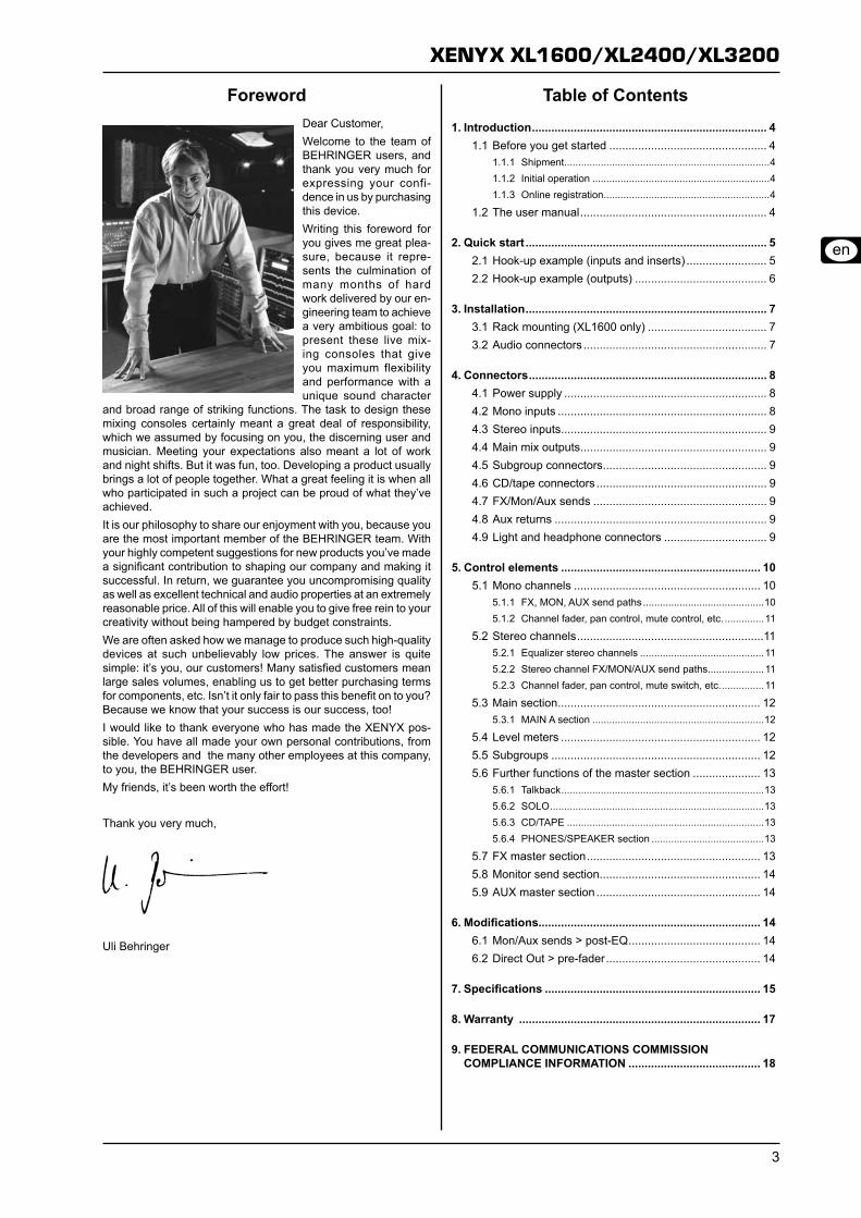
Foreword Dear Customer,Welcome to the team of BEHRINGER users, and thank you very much for expressing your confi-dence in us by purchasing this device.Writing this foreword for you gives me great plea-sure, because it repre-sents the culmination of many months of hard work delivered by our en-gineering team to achieve a very ambitious goal: to present these live mix-ing consoles that give you maximum flexibility and performance with a unique sound character
and broad range of striking functions. The task to design these mixing consoles certainly meant a great deal of responsibility, which we assumed by focusing on you, the discerning user and musician. Meeting your expectations also meant a lot of work and night shifts. But it was fun, too. Developing a product usually brings a lot of people together. What a great feeling it is when all who participated in such a project can be proud of what they’ve achieved.It is our philosophy to share our enjoyment with you, because you are the most important member of the BEHRINGER team. With your highly competent suggestions for new products you’ve made a significant contribution to shaping our company and making it successful. In return, we guarantee you uncompromising quality as well as excellent technical and audio properties at an extremely reasonable price. All of this will enable you to give free rein to your creativity without being hampered by budget constraints. We are often asked how we manage to produce such high-quality devices at such unbelievably low prices. The answer is quite simple: it’s you, our customers! Many satisfied customers mean large sales volumes, enabling us to get better purchasing terms for components, etc. Isn’t it only fair to pass this benefit on to you? Because we know that your success is our success, too! I would like to thank everyone who has made the XENYX pos-sible. You have all made your own personal contributions, from the developers and the many other employees at this company, to you, the BEHRINGER user. My friends, it’s been worth the effort!
Thank you very much,
Uli Behringer
Table of Contents
1. Introduction ......................................................................... 41.1 Before you get started ................................................. 4
1.1.1 Shipment .........................................................................41.1.2 Initial operation ...............................................................41.1.3 Online registration ...........................................................4
1.2 The user manual .......................................................... 4
2. Quick start ........................................................................... 52.1 Hook-up example (inputs and inserts) ......................... 52.2 Hook-up example (outputs) ......................................... 6
3. Installation ........................................................................... 73.1 Rack mounting (XL1600 only) ..................................... 73.2 Audio connectors ......................................................... 7
4. Connectors .......................................................................... 84.1 Power supply ............................................................... 84.2 Mono inputs ................................................................. 84.3 Stereo inputs ................................................................ 94.4 Main mix outputs .......................................................... 94.5 Subgroup connectors ................................................... 94.6 CD/tape connectors ..................................................... 94.7 FX/Mon/Aux sends ...................................................... 94.8 Aux returns .................................................................. 94.9 Light and headphone connectors ................................ 9
5. Control elements .............................................................. 105.1 Mono channels .......................................................... 10
5.1.1 FX, MON, AUX send paths ...........................................105.1.2 Channel fader, pan control, mute control, etc. ..............11
5.2 Stereo channels ..........................................................115.2.1 Equalizer stereo channels ............................................115.2.2 Stereo channel FX/MON/AUX send paths ....................115.2.3 Channel fader, pan control, mute switch, etc. ...............11
5.3 Main section ............................................................... 125.3.1 MAIN A section .............................................................12
5.4 Level meters .............................................................. 125.5 Subgroups ................................................................. 125.6 Further functions of the master section ..................... 13
5.6.1 Talkback ........................................................................135.6.2 SOLO ............................................................................135.6.3 CD/TAPE ......................................................................135.6.4 PHONES/SPEAKER section ........................................13
5.7 FX master section ...................................................... 135.8 Monitor send section .................................................. 145.9 AUX master section ................................................... 14
6. Modifications..................................................................... 146.1 Mon/Aux sends > post-EQ ......................................... 146.2 Direct Out > pre-fader ................................................ 14
7. Specifications ................................................................... 15
8. Warranty ........................................................................... 17
9. FEDERAL COMMUNICATIONS COMMISSION COMPLIANCE INFORMATION ......................................... 18
XENYX XL1600/XL2400/XL3200
Introduction4
Introduction1. Congratulations! By purchasing one of the XENYX mixing con-soles you have acquired a state-of-the-art audio mixer that sets new standards. Right from the very start it has been our goal to design a revolutionary unit that can be used for a great variety of applications. And indeed, this overwhelming mixing console gives you plenty of funtionality and a broad range of connection and expansion options.BEHRINGER is a company with its roots in professional recording studio technology. For many years now we have been successful in developing products for studio and live use. These include mi-crophones and studio gear of all kinds (compressors, enhancers, noise gates, tube processors, headphone amplifiers, digital effects, DI boxes, etc.), monitor and PA speakers as well as professional live and recording mixers. Our entire technical know-how has gone into your XENYX mixing console.
Before you get started1.1
Shipment1.1.1 Your XENYX was carefully packed at the factory, and the pack-aging was designed to protect the unit from damage caused by rough handling. Nevertheless, we recommend that you carefully examine the packaging and its contents for any signs of physical damage that may have occurred during transit.
If the unit is damaged, please do NOT return it to us; +instead, notify your dealer and the shipping company immediately, otherwise claims for damage or replace-ment may not be granted.
We recommend using a case to ensure optimal protec- +tion of the device.
Please always use the original packaging to avoid dam- +age due to storage or shipping.
Never let unsupervised children play with the XENYX +or with its packaging.
Recycle whenever possible. +
Initial operation1.1.2 Ensure adequate air supply, and to avoid overheating do not place the unit near radiators etc.
Blown fuses must be replaced by fuses of the same +type and rating! Please refer to the “Specifications” for details.
Caution
Before changing the fuse, switch off the device and +pull the plug to avoid electric shock or damage to the device.
The power connection is made by using the enclosed cable and the amplifier’s standard IEC receptacle. It meets all of the international safety certification requirements.
Please make sure that all units have a proper earth con- +nection. For your own safety, never remove or disable the earth conductor from the unit or of the AC power cord. The unit must always be connected to the mains outlet with a protective grounding connection.
Extreme output volumes may damage your hearing and/ +or your loudspeakers. Turn down all volume and level controls before you switch on the unit. Always set the volume to an appropriate level.
IMPORTANT NOTES CONCERNING INSTALLATION
The sound quality may diminish within the range of pow- +erful broadcasting stations and high-frequency sources. Increase the distance between the transmitter and the device and use shielded cables for all connections.
Online registration1.1.3 Please remember to register your new BEHRINGER equipment right after your purchase by visiting www.behringer.com (alterna-tively www.behringer.de) and read the terms and conditions of our warranty carefully.Should your BEHRINGER product malfunction, our goal is to have it repaired as quickly as possible. To arrange for warranty service, please contact the retailer from whom the equipment was purchased. Should your BEHRINGER dealer not be located in your vicinity, you may directly contact one of our subsidiaries. Corresponding contact information is included in the original equip-ment packaging (Global Contact Information/European Contact Information). Should your country not be listed, please contact the distributor nearest you. A list of distributors can be found in the support area of our website (www.behringer.com).Registering your purchase and equipment with us helps us process your repair claims quicker and more efficiently.Thank you for your cooperation!
The user manual1.2 The user manual is designed to give you both an overview of the controls, as well as detailed information on how to use them. In or-der to help you understand the links between the controls, we have arranged them in groups according to their function. If you need to know more about specific issues, please visit our website at http://www.behringer.com. Additional information and explanations about various music industry/audio technology terminology can be found on individual product pages as well as in the glossary.
XENYX XL1600/XL2400/XL3200
Quick start 5
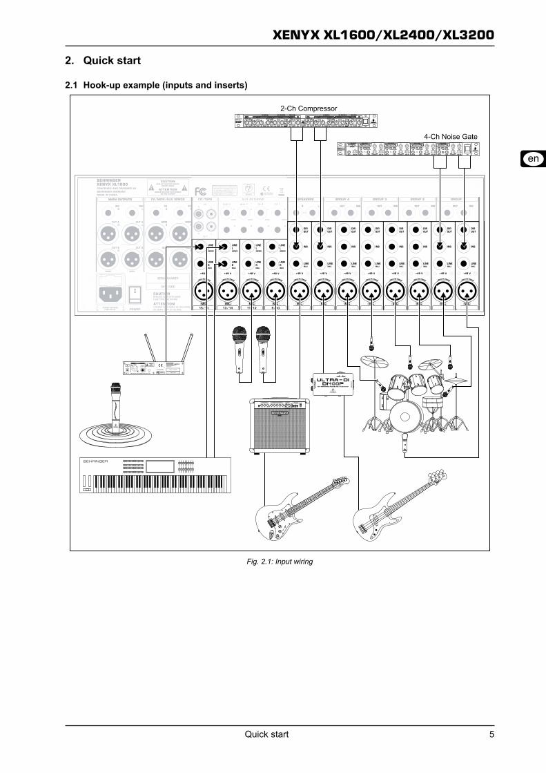
Quick start2.
Hook-up example (inputs and inserts)2.1
Input wiringFig. 2.1:
XENYX XL1600/XL2400/XL3200
Quick start6
Hook-up example (outputs)2.2
Output wiringFig. 2.2:
XENYX XL1600/XL2400/XL3200
Installation 7
Installation3.
Rack mounting (XL1600 only)3.1 The packaging of your XL1600 contains two 19" rack mounts that can be fastened to the side panels of the console.Before you can attach the rack mounts to the mixing console, you need to remove the screws holding the left and right side panels. Then, use these screws to fasten the two rack mounts, each specifically to one side. After attaching the rack mounts, you can mount the mixing console in a standard 19" rack. Be sure to allow for proper air flow around the unit, and do not place the mixing console close to radiators or power amps, so as to avoid overheating.
Only use the screws holding the mixing console side +panels to fasten the 19" rack mounts.
Audio connectors3.2 The ¼" inputs and outputs of the BEHRINGER XENYX mixer are unbalanced mono TS connectors except for the balanced Line inputs on the mono and stereo channels as well as the Main Out connectors. Of course, you can use the mixer with balanced as well as unbalanced ¼" connectors. The CD/TAPE inputs and outputs are stereo RCA connectors.
Make sure that only competent people install your mixer. +They must be sufficiently grounded during and after the installation process. Otherwise, electrostatic discharges may negatively affect the operating characteristics of your equipment.
XLR connectorFig. 3.1:
¼" TRS connectorFig. 3.2:
¼" TS connectorFig. 3.3:
Insert send/return stereo plugFig. 3.4:
¼" headphones connectorFig. 3.5:
RCA cableFig. 3.6:
XENYX XL1600/XL2400/XL3200
Connectors8
Connectors4. Let's begin with the rear panel where the majority of inputs and outputs are located.
Power supply4.1 IEC receptacleThe mains connection is a standard IEC re-ceptacle. An appropri-ate power cord is sup-plied with the unit.
FUSE HOLDERBefore connecting the unit to the mains, ensure that the voltage setting matches your local voltage. Blown fuses should only be replaced by fuses of the same type and rating. Please also read the information given in chapter “Specifications.”
POWERUse the POWER switch to turn on the mixing console. The POWER switch should always be in the “Off” position when you are about to connect your unit to the mains.To disconnect the unit from the mains, pull out the main cord plug. When installing the product, ensure that the plug is easily accessible. If mounting in a rack (XL1600 only), ensure that the mains can be easily disconnected by a plug pull or by an all-pole disconnect switch on or near the rack.
Please note: The POWER switch does not fully discon- +nect the unit from the mains. To disconnect the unit from the mains, pull out the main cord plug or appli-ance coupler. When installing the product, ensure the plug or appliance coupler is readily operable. Unplug the power cord when the unit is not used for prolonged periods of time.
SERIAL NUMBERThis is the serial number of the mixing console.
Mono inputs4.2 MICThe balanced XLR input connects to microphones, DI boxes and multicores. (Multicores are cables that have multiple cores and which run from the so-called stagebox to the mixer.)
Connect the microphone and mute all +mixer outputs before turning on the phantom power to avoid noise when the microphone is turned on. Please wait for about one minute when switching on the mic until the voltage is stable. Only then turn on the input amplification.
Caution! Never use unbalanced XLR connec- +tors (pins 1 and 3 interconnected) on the MIC input jacks, if you want to use phantom power.
+48 VPhantom power is used for operating a capacitor microphone. A control LED lights up next to the switch when the phantom power supply is active. Additional control LEDs are located in each Trim section of the mixer's channels. As a rule, dynamic microphones can still be used with phantom power, provided they are wired in a balanced configuration. In case of doubt, contact the microphone manufacturer!
LINEThis is a ¼" jack connector which connects to line-level signal sources (for example, keyboards, CD players and wireless micro-phone receivers). The input is balanced (TRS connector) but can also be used with unbalanced connectors (TS connector).
INSERTThe INS(ert) connector (¼" stereo jack connector) is used to con-nect to external signal processors. Here you can hook up a com-pressor, noise gate or equalizer to process the signal of a single channel. The insert jack is placed before the fader, EQ and aux send. Please use an insert cable to connect to the insert point.
DIRECT OUTThis ¼" mono jack connector is a direct output which taps the signal after the channel fader to route it to a multi-track recorder, for example. By modifying the circuit board in the unit, the signal can also be tapped pre-fader (see chapter 6).
XENYX XL1600/XL2400/XL3200
Connectors 9
Stereo inputs4.3 LINE L (MONO), LINE RThe stereo channels consist of two line inputs (¼" jacks), one for the left and one for the right channel. The inputs are balanced (TRS connectors), but it is also possible to connect to unbalanced plugs (TS con-nectors). These channels can also be used as mono channels by connecting to the jack labeled “L” (left).
MICThe stereo channels also consist of XLR inputs for connecting to microphones DI boxes and multicores.
+48 VThis is the phantom power for operating capacitor microphones along with the control LED located next to the switch and in the Trim section of the stereo channels.
Main mix outputs4.4 OUT AThe OUT A outputs are balanced XLR connec-tors with a nominal operating level of +4 dBu and provide the main mix signal.
OUT BThe OUT B outputs provide the MAIN B signal the volume level of which can be controlled.
INSERTLike the channel inserts, the INS(ert) con-nectors can be used to hook up a dynamics processor or equalizer for further processing of the mix signal on OUT A.
Subgroup connectors4.5
GROUP OUT 1 - 4These four GROUP OUTS 1 – 4 carry the signals of the individual subgroups. For multi-tracking connect the outputs to the inputs of a multi-track recorder.
INSERTEach subgroup has an insert jack which is labeled INS. Here you can connect to a noise gate, compressor or equalizer to process the subgroup signal as a whole. For example, route your back-ground vocalists to one subgroup bus and then use a compressor to bring the vocals closer together. This makes it sound more like a choir rather than a group of individual soloists. The insert point is placed before the group fader, allowing the dynamics proces-sors (noise gate, compressor, etc.) to be optimally used and not affected by changes in volume level of the group fader. Please use an insert cable to connect to the insert point.
SPEAKERSThe SPEAKERS outputs provide the same signal as the head-phone outputs. Use these outputs to hook up monitor speakers. This is helpful when the mixing console is not located close the performance but in a separate room, such as a TV control room. It is also possible to hook up a stage monitor, ideally one identical to the monitors being used on stage, to listen in on the sound as perceived from the stage monitors.
CD/tape connectors4.6 INThe CD/TAPE input connectors are used to hook up CD players, tape decks or other line-level sources.
OUTThe CD/TAPE output connectors provide the stereo main mix signal to a tape deck or DAT recorder to record your mix. The signal is taken pre-fader so that it will not be influenced by the fader positions.
FX/Mon/Aux sends4.7 FX 1 and 2The FX outputs 1 and 2 provide the signals of the effects buses 1 and 2. These signals may be sent to external effects processors and are routed back over the AUX-RETURN inputs or separate input channels, for example.
MON 1 and 2The monitor outputs 1 and 2 provide the sig-nals of the monitor buses. These signals may be be sent to stage loudspeakers. To prevent interference due to the long cables being used between stage and mixing console, the outputs are balanced XLR connectors. What's more, you have the right connectors when working with multicores.
AUX 1 and 2The AUX outputs 1 and 2 provide the signals of the AUX buses 1 and 2. You can switch these buses pre-fader and post-fader so that they may be used for effects as well as for monitor applications.
Aux returns4.8 AUX RETURNThe stereo AUX inputs 1 und 2 let you connect the mixer to additional equip-ment (players, effects processors, submixers, etc.). The signal is sent to the signal sum.
FX RETURNThe stereo FX RETURN connectors 1 and 2 are linked to the outputs of external effects processors. Depending on the routing, the signals are sent to the subgroup or the main mix bus.
Light and headphone connectors4.9 LAMPSThe LAMPS plugs are for connecting gooseneck lamps with BNC connectors. The power supply is 12 V _ and the total connection load is 5 Watts a lamp.
PHONESThe PHONES outputs (¼" stereo jacks) let you plug in your headphones.
XENYX XL1600/XL2400/XL3200
Control elements10
Control elements5. This chapter describes the various control elements of your mixing console. Each control and switch is explained in full detail.
Mono channels5.1 +48 VThis control LED lights up as long as the phantom power is switched on. The switch is found on the rear panel of the unit.
TrimThe TRIM control adjusts the input gain.
Be sure to set this control fully counter- +clockwise before you connect or discon-nect a signal source to or from one of the inputs.
The dial offers 2 different value ranges. The first value range between 0 and +60 refers to the microphone input, indicating the degree of ampli-fication applied to the input's signal. The second value range between -20 and +40 dB refers to the amplification of the line input. When centered (at 12 o'clock), the line signals are neither boosted nor cut.
80 HzPress the 80 Hz switch to activate the high-pass filter which blends out low-frequency noise (-3 dB at 80 Hz, 18 dB/octave).
EqualizationThe mono input channels provide 4-band equaliza-tion with 2 semi-parametric mids. You can boost or cut the bands up to 15 dB. When in center position (0 dB), the equalizer has a flat response.
HIGHThe high-frequency range is processed with a shelving filter above 12 kHz.
HIGH MIDA semi-parametric peak filter processes the upper mid range be-tween 400 Hz and 8 kHz. The FRE control selects the frequency which is boosted or cut by using the HIGH MID control.
LOW MIDA second semi-parametric peak filter processes the upper mid range. The FREQ control selects the frequency which is boosted or cut by using the HIGH MID control.
LOWThe low-frequency range is processed with a shelving filter below 80 Hz.
EQThe EQ push-button switch activates the equalizer. Toggle the EQ to give you a quick comparison between unprocessed and processed signal.
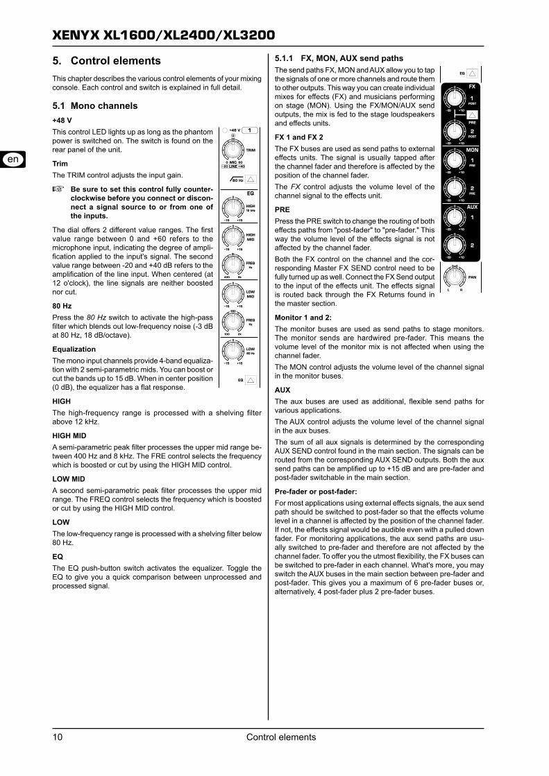
FX, MON, AUX send paths5.1.1 The send paths FX, MON and AUX allow you to tap the signals of one or more channels and route them to other outputs. This way you can create individual mixes for effects (FX) and musicians performing on stage (MON). Using the FX/MON/AUX send outputs, the mix is fed to the stage loudspeakers and effects units.
FX 1 and FX 2The FX buses are used as send paths to external effects units. The signal is usually tapped after the channel fader and therefore is affected by the position of the channel fader.The FX control adjusts the volume level of the channel signal to the effects unit.
PREPress the PRE switch to change the routing of both effects paths from "post-fader" to "pre-fader." This way the volume level of the effects signal is not affected by the channel fader.Both the FX control on the channel and the cor-responding Master FX SEND control need to be fully turned up as well. Connect the FX Send output to the input of the effects unit. The effects signal is routed back through the FX Returns found in the master section.
Monitor 1 and 2:The monitor buses are used as send paths to stage monitors. The monitor sends are hardwired pre-fader. This means the volume level of the monitor mix is not affected when using the channel fader.The MON control adjusts the volume level of the channel signal in the monitor buses.
AUXThe aux buses are used as additional, flexible send paths for various applications.The AUX control adjusts the volume level of the channel signal in the aux buses.The sum of all aux signals is determined by the corresponding AUX SEND control found in the main section. The signals can be routed from the corresponding AUX SEND outputs. Both the aux send paths can be amplified up to +15 dB and are pre-fader and post-fader switchable in the main section.
Pre-fader or post-fader:For most applications using external effects signals, the aux send path should be switched to post-fader so that the effects volume level in a channel is affected by the position of the channel fader. If not, the effects signal would be audible even with a pulled down fader. For monitoring applications, the aux send paths are usu-ally switched to pre-fader and therefore are not affected by the channel fader. To offer you the utmost flexibility, the FX buses can be switched to pre-fader in each channel. What's more, you may switch the AUX buses in the main section between pre-fader and post-fader. This gives you a maximum of 6 pre-fader buses or, alternatively, 4 post-fader plus 2 pre-fader buses.
XENYX XL1600/XL2400/XL3200
Control elements 11
Channel fader, pan control, mute control, etc.5.1.2 PANThe PAN control determines the position of the channel signal in the stereo mix as well as the subgroup to which the channel signal is routed.
MUTEThe MUTE switch mutes the channel. This means that the channel signal has been removed from the main mix and subgroups. At the same time the FX, monitor and aux paths of the respective channel are muted as well. The corresponding MUTE LED indicates that the channel has been muted.
SOLOUse the solo function to listen in on a channel. Press the channel's SOLO switch to hear the signal on your headphones. Simultaneously, the monitor meter 1/2 switches to the solo signal, allowing you to level the signal correctly (see chapter X). The signal to be listened in on is tapped either before (PFL, mono) or behind (AFL, stereo) the channel fader and the pan control (depending on the state of the PFL/AFL switch. The corresponding LED lights up when the solo function is activated.
CLIPThe CLIP LED lights up as soon as the channel's level is too high. In this case, reduce the channel's input amplification with the TRIM control.
SIGThe SIG LED lights up when a channel's signal is higher than -20 dB. The LED is not affected by the fader. The signals are indicated even when the fader is pulled down and the channel is muted.
FaderThe channel fader adjusts the level of the channel signal as part of the main mix (or submix).
1-2, 3-4, MIXThe routing switch routes the signal to the respective subgroup or the main mix or both. The XENYX features 4 subgroups. The PAN control determines the group to which the signal is routed (fully left: Sub 1 or 3, fully right: Sub 2 or 4).
Stereo channels5.2 +48 VThis control LED lights up when the phantom power is activated. The switch is located on the rear panel of the unit.
MIC TRIMThe MIC TRIM control adjusts amplification of the microphone input. The amplification ranges between 0 and +60 dB.
Be sure to set this control fully counter- +clockwise before you connect or discon-nect a signal source to or from one of the inputs.
80 HzPress the 80 Hz switch to activate the high-pass filter which blends out low-frequency noise (-3 dB at 80 Hz, 18 dB/octave).
LINE TRIMThe LINE TRIM control adjusts the amplification of the LINE input, ranging between -20 and +20 dB. When centered (at 12 o'clock), the line signal is neither boosted nor cut.
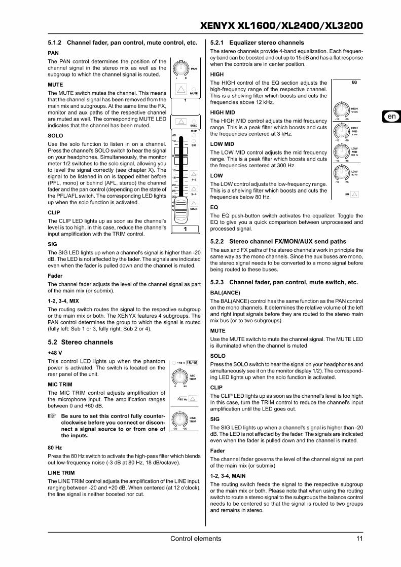
Equalizer stereo channels5.2.1 The stereo channels provide 4-band equalization. Each frequen-cy band can be boosted and cut up to 15 dB and has a flat response when the controls are in center position.
HIGHThe HIGH control of the EQ section adjusts the high-frequency range of the respective channel. This is a shelving filter which boosts and cuts the frequencies above 12 kHz.
HIGH MIDThe HIGH MID control adjusts the mid frequency range. This is a peak filter which boosts and cuts the frequencies centered at 3 kHz.
LOW MIDThe LOW MID control adjusts the mid frequency range. This is a peak filter which boosts and cuts the frequencies centered at 300 Hz.
LOWThe LOW control adjusts the low-frequency range. This is a shelving filter which boosts and cuts the frequencies below 80 Hz.
EQThe EQ push-button switch activates the equalizer. Toggle the EQ to give you a quick comparison between unprocessed and processed signal.
Stereo channel FX/MON/AUX send paths5.2.2 The aux and FX paths of the stereo channels work in principle the same way as the mono channels. Since the aux buses are mono, the stereo signal needs to be converted to a mono signal before being routed to these buses.
Channel fader, pan control, mute switch, etc.5.2.3 BAL(ANCE)The BAL(ANCE) control has the same function as the PAN control on the mono channels. It determines the relative volume of the left and right input signals before they are routed to the stereo main mix bus (or to two subgroups).
MUTEUse the MUTE switch to mute the channel signal. The MUTE LED is illuminated when the channel is muted
SOLOPress the SOLO switch to hear the signal on your headphones and simultaneously see it on the monitor display 1/2). The correspond-ing LED lights up when the solo function is activated.
CLIPThe CLIP LED lights up as soon as the channel's level is too high. In this case, turn the TRIM control to reduce the channel's input amplification until the LED goes out.
SIGThe SIG LED lights up when a channel's signal is higher than -20 dB. The LED is not affected by the fader. The signals are indicated even when the fader is pulled down and the channel is muted.
FaderThe channel fader governs the level of the channel signal as part of the main mix (or submix)
1-2, 3-4, MAINThe routing switch feeds the signal to the respective subgroup or the main mix or both. Please note that when using the routing switch to route a stereo signal to the subgroups the balance control needs to be centered so that the signal is routed to two groups and remains in stereo.
XENYX XL1600/XL2400/XL3200
Control elements12
Main section5.3
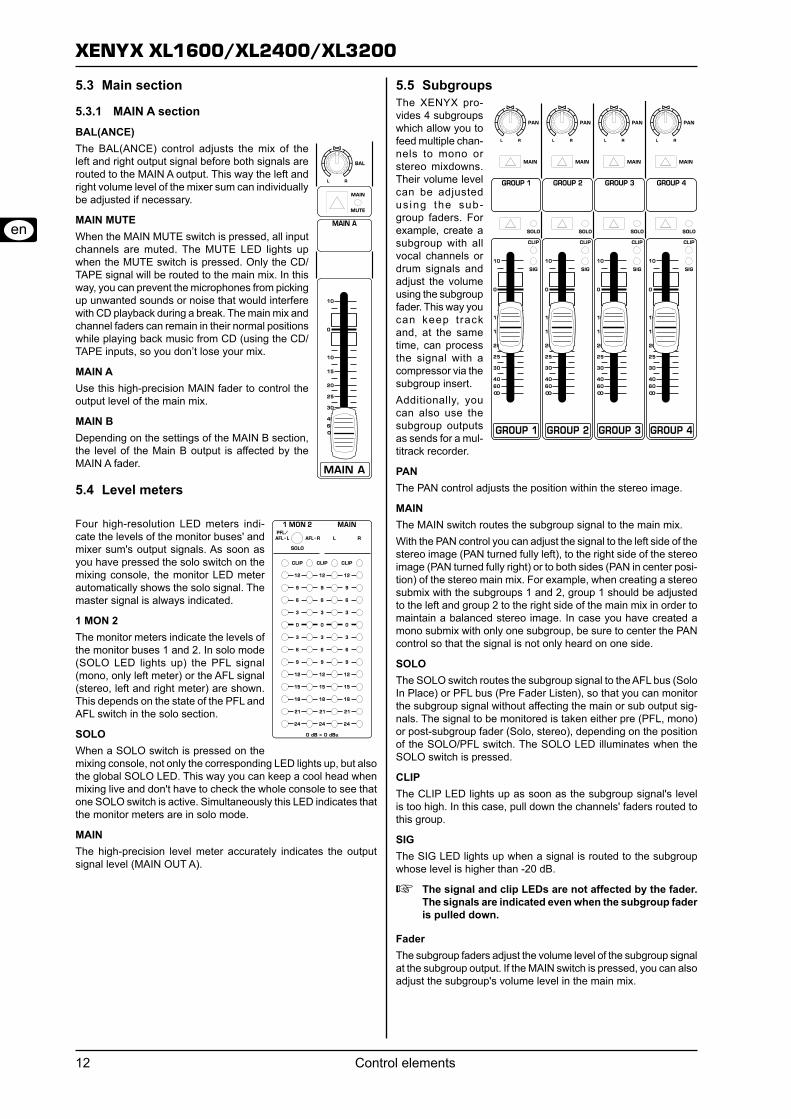
MAIN A section5.3.1 BAL(ANCE)The BAL(ANCE) control adjusts the mix of the left and right output signal before both signals are routed to the MAIN A output. This way the left and right volume level of the mixer sum can individually be adjusted if necessary.
MAIN MUTEWhen the MAIN MUTE switch is pressed, all input channels are muted. The MUTE LED lights up when the MUTE switch is pressed. Only the CD/TAPE signal will be routed to the main mix. In this way, you can prevent the microphones from picking up unwanted sounds or noise that would interfere with CD playback during a break. The main mix and channel faders can remain in their normal positions while playing back music from CD (using the CD/TAPE inputs, so you don’t lose your mix.
MAIN AUse this high-precision MAIN fader to control the output level of the main mix.
MAIN BDepending on the settings of the MAIN B section, the level of the Main B output is affected by the MAIN A fader.
Level meters5.4
Four high-resolution LED meters indi-cate the levels of the monitor buses' and mixer sum's output signals. As soon as you have pressed the solo switch on the mixing console, the monitor LED meter automatically shows the solo signal. The master signal is always indicated.
1 MON 2The monitor meters indicate the levels of the monitor buses 1 and 2. In solo mode (SOLO LED lights up) the PFL signal (mono, only left meter) or the AFL signal (stereo, left and right meter) are shown. This depends on the state of the PFL and AFL switch in the solo section.
SOLOWhen a SOLO switch is pressed on the mixing console, not only the corresponding LED lights up, but also the global SOLO LED. This way you can keep a cool head when mixing live and don't have to check the whole console to see that one SOLO switch is active. Simultaneously this LED indicates that the monitor meters are in solo mode.
MAINThe high-precision level meter accurately indicates the output signal level (MAIN OUT A).
Subgroups5.5 The XENYX pro-vides 4 subgroups which allow you to feed multiple chan-nels to mono or stereo mixdowns. Their volume level can be adjusted us ing the sub-group faders. For example, create a subgroup with all vocal channels or drum signals and adjust the volume using the subgroup fader. This way you can keep track and, at the same time, can process the signal with a compressor via the subgroup insert.Additionally, you can also use the subgroup outputs as sends for a mul-titrack recorder.
PANThe PAN control adjusts the position within the stereo image.
MAINThe MAIN switch routes the subgroup signal to the main mix.With the PAN control you can adjust the signal to the left side of the stereo image (PAN turned fully left), to the right side of the stereo image (PAN turned fully right) or to both sides (PAN in center posi-tion) of the stereo main mix. For example, when creating a stereo submix with the subgroups 1 and 2, group 1 should be adjusted to the left and group 2 to the right side of the main mix in order to maintain a balanced stereo image. In case you have created a mono submix with only one subgroup, be sure to center the PAN control so that the signal is not only heard on one side.
SOLOThe SOLO switch routes the subgroup signal to the AFL bus (Solo In Place) or PFL bus (Pre Fader Listen), so that you can monitor the subgroup signal without affecting the main or sub output sig-nals. The signal to be monitored is taken either pre (PFL, mono) or post-subgroup fader (Solo, stereo), depending on the position of the SOLO/PFL switch. The SOLO LED illuminates when the SOLO switch is pressed.
CLIPThe CLIP LED lights up as soon as the subgroup signal's level is too high. In this case, pull down the channels' faders routed to this group.
SIGThe SIG LED lights up when a signal is routed to the subgroup whose level is higher than -20 dB.
The signal and clip LEDs are not affected by the fader. +The signals are indicated even when the subgroup fader is pulled down.
FaderThe subgroup faders adjust the volume level of the subgroup signal at the subgroup output. If the MAIN switch is pressed, you can also adjust the subgroup's volume level in the main mix.
XENYX XL1600/XL2400/XL3200
Control elements 13
Further functions of the master section5.6
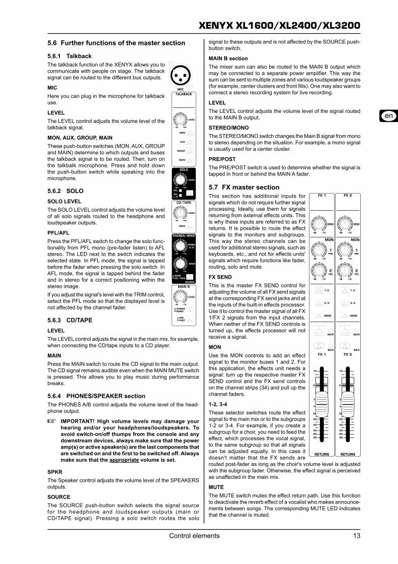
Talkback5.6.1 The talkback function of the XENYX allows you to communicate with people on stage. The talkback signal can be routed to the different bus outputs.
MICHere you can plug in the microphone for talkback use.
LEVELThe LEVEL control adjusts the volume level of the talkback signal.
MON, AUX, GROUP, MAINThese push-button switches (MON, AUX, GROUP and MAIN) determine to which outputs and buses the talkback signal is to be routed. Then, turn on the talkbalk microphone. Press and hold down the push-button switch while speaking into the microphone.
SOLO5.6.2 SOLO LEVELThe SOLO LEVEL control adjusts the volume level of all solo signals routed to the headphone and loudspeaker outputs.
PFL/AFLPress the PFL/AFL switch to change the solo func-tionality from PFL mono (pre-fader listen) to AFL stereo. The LED next to the switch indicates the selected state. In PFL mode, the signal is tapped before the fader when pressing the solo switch. In AFL mode, the signal is tapped behind the fader and in stereo for a correct positioning within the stereo image.If you adjust the signal's level with the TRIM control, select the PFL mode so that the displayed level is not affected by the channel fader.
CD/TAPE5.6.3 LEVELThe LEVEL control adjusts the signal in the main mix, for example, when connecting the CD/tape inputs to a CD player.
MAINPress the MAIN switch to route the CD signal to the main output. The CD signal remains audible even when the MAIN MUTE switch is pressed. This allows you to play music during performance breaks.
PHONES/SPEAKER section5.6.4 The PHONES A/B control adjusts the volume level of the head-phone output.
IMPORTANT! High volume levels may damage your +hearing and/or your headphones/loudspeakers. To avoid switch-on/off thumps from the console and any downstream devices, always make sure that the power amp(s) or active speaker(s) are the last components that are switched on and the first to be switched off. Always make sure that the appropriate volume is set.
SPKRThe Speaker control adjusts the volume level of the SPEAKERS outputs.
SOURCEThe SOURCE push-button switch selects the signal source for the headphone and loudspeaker outputs (main or CD/TAPE signal). Pressing a solo switch routes the solo
signal to these outputs and is not affected by the SOURCE push-button switch.
MAIN B sectionThe mixer sum can also be routed to the MAIN B output which may be connected to a separate power amplifier. This way the sum can be sent to multiple zones and various loudspeaker groups (for example, center clusters and front fills). One may also want to connect a stereo recording system for live recording.
LEVELThe LEVEL control adjusts the volume level of the signal routed to the MAIN B output.
STEREO/MONOThe STEREO/MONO switch changes the Main B signal from mono to stereo depending on the situation. For example, a mono signal is usually used for a center cluster.
PRE/POSTThe PRE/POST switch is used to determine whether the signal is tapped in front or behind the MAIN A fader.
FX master section5.7 This section has additional inputs for signals which do not require further signal processing. Ideally, use them for signals returning from external effects units. This is why these inputs are referred to as FX returns. It is possible to route the effect signals to the monitors and subgroups. This way the stereo channels can be used for additional stereo signals, such as keyboards, etc., and not for effects units' signals which require functions like fader, routing, solo and mute.
FX SENDThis is the master FX SEND control for adjusting the volume of all FX send signals at the corresponding FX send jacks and at the inputs of the built-in effects processor. Use it to control the master signal of all FX 1/FX 2 signals from the input channels. When neither of the FX SEND controls is turned up, the effects processor will not receive a signal.
MONUse the MON controls to add an effect signal to the monitor buses 1 and 2. For this application, the effects unit needs a signal: turn up the respective master FX SEND control and the FX send controls on the channel strips (34) and pull up the channel faders.
1-2, 3-4These selector switches route the effect signal to the main mix or to the subgroups 1-2 or 3-4. For example, if you create a subgroup for a choir, you need to feed the effect, which processes the vocal signal, to the same subgroup so that all signals can be adjusted equally. In this case it doesn't matter that the FX sends are routed post-fader as long as the choir's volume level is adjusted with the subgroup fader. Otherwise, the effect signal is perceived as unaffected in the main mix.
MUTEThe MUTE switch mutes the effect return path. Use this function to deactivate the reverb effect of a vocalist who makes announce-ments between songs. The corresponding MUTE LED indicates that the channel is muted.
XENYX XL1600/XL2400/XL3200
Modifications14
SOLOPress the SOLO switch to listen in on the effect signal on the head-phones/speakers as well as see it on the monitor meter 1/2. The corresponding LED lights up when the solo function is activated.
FX RETURNThe FX return fader adjusts the volume level of the returned effect signal in the main mix and subgroups (this depends on the routing switch you have pressed).
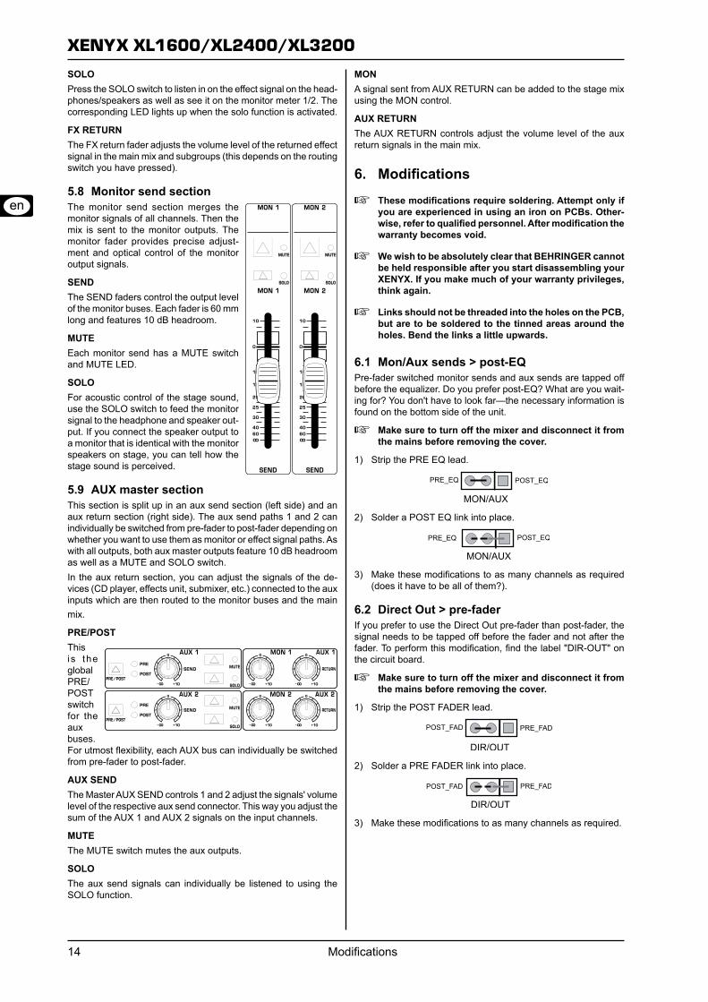
Monitor send section5.8 The monitor send section merges the monitor signals of all channels. Then the mix is sent to the monitor outputs. The monitor fader provides precise adjust-ment and optical control of the monitor output signals.
SENDThe SEND faders control the output level of the monitor buses. Each fader is 60 mm long and features 10 dB headroom.
MUTEEach monitor send has a MUTE switch and MUTE LED.
SOLOFor acoustic control of the stage sound, use the SOLO switch to feed the monitor signal to the headphone and speaker out-put. If you connect the speaker output to a monitor that is identical with the monitor speakers on stage, you can tell how the stage sound is perceived.
AUX master section5.9 This section is split up in an aux send section (left side) and an aux return section (right side). The aux send paths 1 and 2 can individually be switched from pre-fader to post-fader depending on whether you want to use them as monitor or effect signal paths. As with all outputs, both aux master outputs feature 10 dB headroom as well as a MUTE and SOLO switch.In the aux return section, you can adjust the signals of the de-vices (CD player, effects unit, submixer, etc.) connected to the aux inputs which are then routed to the monitor buses and the main mix.
PRE/POSTThis is the global PRE/POST switch for the aux buses. For utmost flexibility, each AUX bus can individually be switched from pre-fader to post-fader.
AUX SENDThe Master AUX SEND controls 1 and 2 adjust the signals' volume level of the respective aux send connector. This way you adjust the sum of the AUX 1 and AUX 2 signals on the input channels.
MUTEThe MUTE switch mutes the aux outputs.
SOLOThe aux send signals can individually be listened to using the SOLO function.
MONA signal sent from AUX RETURN can be added to the stage mix using the MON control.
AUX RETURNThe AUX RETURN controls adjust the volume level of the aux return signals in the main mix.
Modifications6.
These modifications require soldering. Attempt only if +you are experienced in using an iron on PCBs. Other-wise, refer to qualified personnel. After modification the warranty becomes void.
We wish to be absolutely clear that BEHRINGER cannot +be held responsible after you start disassembling your XENYX. If you make much of your warranty privileges, think again.
Links should not be threaded into the holes on the PCB, +but are to be soldered to the tinned areas around the holes. Bend the links a little upwards.
Mon/Aux sends > post-EQ6.1 Pre-fader switched monitor sends and aux sends are tapped off before the equalizer. Do you prefer post-EQ? What are you wait-ing for? You don't have to look far—the necessary information is found on the bottom side of the unit.
Make sure to turn off the mixer and disconnect it from +the mains before removing the cover.
Strip the PRE EQ lead.1)
Solder a POST EQ link into place.2)
Make these modifications to as many channels as required 3) (does it have to be all of them?).
Direct Out > pre-fader6.2 If you prefer to use the Direct Out pre-fader than post-fader, the signal needs to be tapped off before the fader and not after the fader. To perform this modification, find the label "DIR-OUT" on the circuit board.
Make sure to turn off the mixer and disconnect it from +the mains before removing the cover.
Strip the POST FADER lead.1)
Solder a PRE FADER link into place.2)
Make these modifications to as many channels as required.3)
XENYX XL1600/XL2400/XL3200
Specifications 15
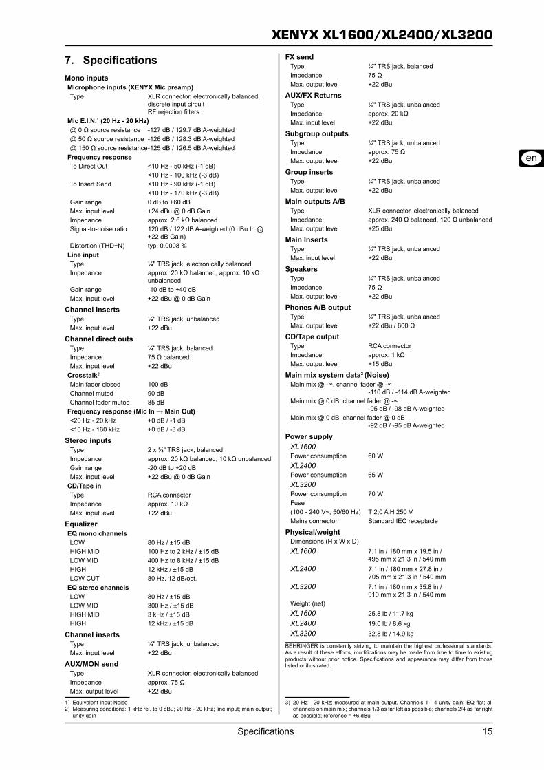
Specifications7. Mono inputsMicrophone inputs (XENYX Mic preamp)Type XLR connector, electronically balanced,
discrete input circuit RF rejection filters
Mic E.I.N.1 (20 Hz - 20 kHz)@ 0 Ω source resistance -127 dB / 129.7 dB A-weighted@ 50 Ω source resistance -126 dB / 128.3 dB A-weighted@ 150 Ω source resistance -125 dB / 126.5 dB A-weighted
Frequency responseTo Direct Out <10 Hz - 50 kHz (-1 dB) <10 Hz - 100 kHz (-3 dB)To Insert Send <10 Hz - 90 kHz (-1 dB) <10 Hz - 170 kHz (-3 dB)Gain range 0 dB to +60 dBMax. input level +24 dBu @ 0 dB GainImpedance approx. 2.6 kΩ balancedSignal-to-noise ratio 120 dB / 122 dB A-weighted (0 dBu In @
+22 dB Gain)Distortion (THD+N) typ. 0.0008 %
Line inputType ¼" TRS jack, electronically balancedImpedance approx. 20 kΩ balanced, approx. 10 kΩ
unbalancedGain range -10 dB to +40 dBMax. input level +22 dBu @ 0 dB Gain
Channel insertsType ¼" TRS jack, unbalancedMax. input level +22 dBu
Channel direct outsType ¼" TRS jack, balancedImpedance 75 Ω balancedMax. input level +22 dBu
Crosstalk2
Main fader closed 100 dBChannel muted 90 dBChannel fader muted 85 dB
Frequency response (Mic In → Main Out)<20 Hz - 20 kHz +0 dB / -1 dB<10 Hz - 160 kHz +0 dB / -3 dB
Stereo inputsType 2 x ¼" TRS jack, balancedImpedance approx. 20 kΩ balanced, 10 kΩ unbalancedGain range -20 dB to +20 dBMax. input level +22 dBu @ 0 dB Gain
CD/Tape inType RCA connectorImpedance approx. 10 kΩMax. input level +22 dBu
EqualizerEQ mono channelsLOW 80 Hz / ±15 dBHIGH MID 100 Hz to 2 kHz / ±15 dBLOW MID 400 Hz to 8 kHz / ±15 dBHIGH 12 kHz / ±15 dBLOW CUT 80 Hz, 12 dB/oct.
EQ stereo channelsLOW 80 Hz / ±15 dBLOW MID 300 Hz / ±15 dBHIGH MID 3 kHz / ±15 dBHIGH 12 kHz / ±15 dB
Channel insertsType ¼" TRS jack, unbalancedMax. input level +22 dBu
AUX/MON sendType XLR connector, electronically balancedImpedance approx. 75 ΩMax. output level +22 dBu
1) Equivalent Input Noise2) Measuring conditions: 1 kHz rel. to 0 dBu; 20 Hz - 20 kHz; line input; main output;
unity gain
FX sendType ¼" TRS jack, balancedImpedance 75 ΩMax. output level +22 dBu
AUX/FX ReturnsType ¼" TRS jack, unbalancedImpedance approx. 20 kΩMax. input level +22 dBu
Subgroup outputsType ¼" TRS jack, unbalancedImpedance approx. 75 ΩMax. output level +22 dBu
Group insertsType ¼" TRS jack, unbalancedMax. output level +22 dBu
Main outputs A/BType XLR connector, electronically balancedImpedance approx. 240 Ω balanced, 120 Ω unbalancedMax. output level +25 dBu
Main InsertsType ¼" TRS jack, unbalancedMax. input level +22 dBu
SpeakersType ¼" TRS jack, unbalancedImpedance 75 ΩMax. output level +22 dBu
Phones A/B outputType ¼" TRS jack, unbalancedMax. output level +22 dBu / 600 Ω
CD/Tape outputType RCA connectorImpedance approx. 1 kΩMax. output level +15 dBu
Main mix system data3 (Noise)Main mix @ -∞, channel fader @ -∞
-110 dB / -114 dB A-weightedMain mix @ 0 dB, channel fader @ -∞
-95 dB / -98 dB A-weightedMain mix @ 0 dB, channel fader @ 0 dB
-92 dB / -95 dB A-weighted
Power supplyXL1600Power consumption 60 WXL2400Power consumption 65 WXL3200Power consumption 70 WFuse(100 - 240 V~, 50/60 Hz) T 2,0 A H 250 VMains connector Standard IEC receptacle
Physical/weightDimensions (H x W x D)XL1600 7.1 in / 180 mm x 19.5 in /
495 mm x 21.3 in / 540 mmXL2400 7.1 in / 180 mm x 27.8 in / 705 mm x 21.3 in / 540 mmXL3200 7.1 in / 180 mm x 35.8 in /
910 mm x 21.3 in / 540 mmWeight (net) XL1600 25.8 lb / 11.7 kgXL2400 19.0 lb / 8.6 kgXL3200 32.8 lb / 14.9 kg
BEHRINGER is constantly striving to maintain the highest professional standards. As a result of these efforts, modifications may be made from time to time to existing products without prior notice. Specifications and appearance may differ from those listed or illustrated.
3) 20 Hz - 20 kHz; measured at main output. Channels 1 - 4 unity gain; EQ flat; all channels on main mix; channels 1/3 as far left as possible; channels 2/4 as far right as possible; reference = +6 dBu
XENYX XL1600/XL2400/XL3200
Specifications16
XENYX XL1600/XL2400/XL3200
Warranty 17
Technical specifications and appearance are subject to change without notice. The information contained herein is correct at the time of printing. BEHRINGER accepts no liability for any loss which may be suffered by any person who relies either wholly or in part upon any description, photograph or statement contained herein. Colors and specifications may vary slightly from product. Products are sold through our authorized dealers only. Distributors and dealers are not agents of BEHRINGER and have absolutely no authority to bind BEHRINGER by any express or implied undertaking or representation. No part of this manual may be reproduced or transmitted in any form or by any means, electronic or mechanical, including photocopying and recording of any kind, for any purpose, without the express written permission of BEHRINGER International GmbH.
ALL RIGHTS RESERVED. © 2009 BEHRINGER International GmbH, Hanns-Martin-Schleyer-Str. 36-38, 47877 Willich, Germany, Tel. +49 2154 9206 0, Fax +49 2154 9206 4903
Warranty 8. Other warranty rights and national law § 1
1. This warranty does not exclude or limit the buyer’s statutory rights pro-vided by national law, in particular, any such rights against the seller that arise from a legally effective purchase contract. 2. The warranty regulations mentioned herein are applicable unless they constitute an infringement of national warranty law.
Online registration § 2 Please do remember to register your new BEHRINGER equipment right after your purchase by visiting http://www.behringer.com and kindly read the terms and conditions of our warranty carefully. Registering your pur-chase and equipment with us helps us process your repair claims quicker and more efficiently. Thank you for your cooperation!
Warranty § 3 1. BEHRINGER (BEHRINGER International GmbH including all BEH-RINGER subsidiaries, except BEHRINGER Japan) warrants the mechanical and electronic components of this product to be free of defects in material and workmanship for a period of one (1) year* from the original date of purchase, in accordance with the warranty regulations described below. If the product shows any defects within the specified warranty period that are not excluded from this warranty as described under § 5, BEHRINGER shall, at its discretion, either replace the product by providing a new or reconditioned product or repair the product using suitable new or recon-ditioned parts. In the case that other parts are used which constitute an improvement, BEHRINGER may, at its discretion, charge the customer for the additional cost of these parts. In case BEHRINGER decides to replace the product, this warranty shall apply to the replacement product for the remaining initial warranty period, i.e one year* from the date of purchase of the initial product. 2. If the warranty claim proves to be justified, the product will be returned to the user freight prepaid. 3. Warranty claims other than those indicated above are expressly ex-cluded.
Return authorization number § 4 1. To obtain warranty service, the buyer (or his authorized dealer) must call BEHRINGER during normal business hours BEFORE returning the product. All inquiries must be accompanied by a description of the problem. The buyer or his authorized dealer will receive a return authorization number. 2. Subsequently, the product must be returned in its original shipping carton, together with the return authorization number. The return shipment address will be indicated by BEHRINGER. 3. Shipments without freight prepaid will not be accepted.
Warranty regulations§ 5 1. Warranty services will be furnished only if the product is accompanied by a copy of the original retail dealer’s invoice. Any product deemed eligible for repair or replacement under the terms of this warranty will be repaired or replaced.2. If the product needs to be modified or adapted in order to comply with applicable technical or safety standards on a national or local level, in any country which is not the country for which the product was originally devel-oped and manufactured, this modification/adaptation shall not be considered a defect in materials or workmanship. The warranty does not cover any such modification/adaptation, irrespective of whether it was carried out properly or not. Under the terms of this warranty, BEHRINGER shall not be held responsible for any cost resulting from such a modification/adaptation. 3. Free inspections and maintenance/repair work are expressly excluded from this warranty, in particular, if caused by improper handling of the product by the user. This also applies to defects caused by normal wear and tear, in particular, of faders, crossfaders, potentiometers, keys/buttons, tubes, guitar strings, illuminants and similar parts.
4. Damage/defects caused by the following conditions are not covered by this warranty:
improper handling, neglect or failure to operate the unit in compli- =ance with the instructions given in BEHRINGER user or service manuals. connection or operation of the unit in any way that does not comply =with the technical or safety regulations applicable in the country where the product is used.damage/defects caused by force majeure or any other condition =that is beyond the control of BEHRINGER.
5. Any repair or opening of the unit carried out by unauthorized personnel (user included) will void the warranty. 6. If an inspection of the product by BEHRINGER shows that the defect in question is not covered by the warranty, 7. Products which do not meet the terms of this warranty will be repaired exclusively at the buyer’s expense. BEHRINGER will inform the buyer of any such circumstance. If the buyer fails to submit a written repair order within 6 weeks after notification, BEHRINGER will return the unit. Costs for freight and packing will be invoiced separately C.O.D. When the buyer has sent in a written repair order such costs will also be invoiced separately.
Warranty transferability§ 6 This warranty is extended exclusively to the original buyer (customer of retail dealer) and is not transferable to anyone who may subsequently purchase this product. No other person (retail dealer, etc.) shall be entitled to give any warranty promise on behalf of BEHRINGER.
Claim for damages§ 7 Failure of BEHRINGER to provide proper warranty service shall not entitle the buyer to claim (consequential) damages. In no event shall the liability of BEHRINGER exceed the invoiced value of the product.* Customers in the European Union please contact BEHRINGER Germany Support for further details.
FEDERAL COMMUNICATIONS 9. COMMISSION COMPLIANCE INFORMATION
Responsible party name: BEHRINGER USA, Inc.Address: 18912 North Creek Parkway,
Suite 200 Bothell, WA 98011, USA
Phone/Fax No.: Phone: +1 425 672 0816 Fax: +1 425 673 7647
hereby declares that the product
XENYX XL1600
XENYX XL2400
XENYX XL3200
complies with the FCC rules as mentioned in the following paragraph:This equipment has been tested and found to comply with the limits for a Class B digital device, pursuant to part 15 of the FCC Rules. These limits are designed to provide reasonable protection against harmful interference in a residential installation. This equipment generates, uses and can radiate radio frequency energy and, if not installed and used in accordance with the instructions, may cause harmful interference to radio communications. However, there is no guarantee that interference will not occur in a particular installation. If this equipment does cause harmful interference to radio or television reception, which can be determined by turning the equipment off and on, the user is encouraged to try to correct the interference by one or more of the following measures:
Reorient or relocate the receiving antenna.•Increase the separation between the equipment and •receiver.Connect the equipment into an outlet on a circuit diffe-•rent from that to which the receiver is connected.Consult the dealer or an experienced radio/TV technician •for help.
This device complies with Part 15 of the FCC rules. Operation is subject to the following two conditions:(1) this device may not cause harmful interference, and (2) this device must accept any interference received, including interference that may cause undesired operation.
Important information:Changes or modifications to the equipment not expressly approved by BEHRINGER USA can void the user’s authority to use the equipment.
XENYX XL1600/XL2400/XL3200