Embed Size (px)
Citation preview
R
Copley Controls, 20 Dan Road, Canton, MA 02021, USA Tel: 781-828-8090 Fax: 781-828-6547 Tech Support: E-mail: [email protected], Internet: http://www.copleycontrols.com Page 1 of 26
DIGITAL SERVO DRIVE
for BRUSHLESS/BRUSH MOTORSXenus XSL
DESCRIPTIONXenus combines CANopen networking with 100% digital control of brushless or brush motors in an off-line powered package that can operate from single or three-phase mains with continuous power output to 4 kW.Xenus is offered in two versions based on the type of feedback. Standard models supports digital quadrature or analog sin/cos encoders. Resolver feedback is available in “-R” models which convert the resolver angle into quadrature encoder signals for using Xenus with external controllers.Xenus operates as a Motion Control Device under the DSP-402 protocol of the CANopen DS-301 V4.01 (EN 50325-4) application layer. DSP-402 modes supported include: Profile Position, Profile Velocity, Profile Torque, Interpolated Position (PVT), and Homing.Drive commissioning is fast and simple using CME 2 software operating under Windows® communicating with Xenus via CAN or an RS-232 link. CAN address selection is by a 16-position rotary switch on the front panel. If there are more than fifteen devices on a CAN bus, the additional address bits needed can come from programmable inputs, or can be set in flash memory. Profile Position Mode does a complete motion index on command with S-curve acceleration & deceleration, top speed, and distance programmable. In PVT mode, the controller sends out a sequence of points each of which is an increment of a larger, more complex move than a single index or profile. The drive then uses cubic polynomial interpolation to “connect the dots” such that the motor reaches each point (Position) at the specified velocity (Velocity) at the prescribed time (Time).
Homing mode is configurable to work with a variety of limit, index, and home switches such that the drive moves the motor into a position that has an absolute reference to some part of the machine. Eleven logic inputs are programmable as limit or home switches, stepper/encoder pulse inputs, reset, digital torque or velocity reference, or motor-temperature. A twelfth input is dedicated to the drive Enable function. Three programmable logic outputs are for reporting a drive fault or other status indications. A fourth optically-isolated output can drive a motor brake from the external +24 Vdc power supply or can be programmed as a logic output.In addition to CANopen motion commands, Xenus can operate as a stand-alone drive. Current and velocity modes accept ±10 Vdc analog, digital 50% PWM or PWM/polarity inputs. In position mode inputs can be incremental position commands from step-motor controllers in Pulse/Direction or CW/CCW format, ±10 Vdc analog, or A/B quadrature commands from a master-encoder. Pulse to position ratio is programmable for electronic gearing.Power output of the drive varies with the input power which can range from 100 to 240 Vac, and from 47 to 63 Hz. Either single or three phase mains can be used giving Xenus the ability to work in the widest possible range of industrial settings. Signal and control circuits are isolated from the high-voltage power supply and inverter stage that connect to the mains. A +24 Vdc input powers control circuits for keep-alive operation permitting the drive power stage to be completely powered down without losing position information or communications with the control system.
Control Modes • Indexer, Point-to-Point, PVT • Camming, Gearing, Position, Velocity, Torque
Command Interface • CANopen • ASCII and discrete I/O • Stepper commands • ±10V position/velocity/torque command • PWM velocity/torque command • Master encoder (Gearing/Camming)
Communications • CANopen • RS232
Feedback • Digital Quad A/B encoder • Secondary encoder / emulated encoder out • Analog sin/cos encoder • Resolver • Digital Halls
I/O - Digital • 12 inputs, 4 outputs
Accessories • External regen resistors • External edge filter
Dimensions: mm [in] • 7.5 x 5.5 x 2.5 [191 x 140 x 64]
Model Vac Ic Ip
XSL-230-18 100 - 240 6 18
XSL-230-36 100 - 240 12 36
XSL-230-40 100 - 240 20 40
Resolver version: append -R
Copley Controls, 20 Dan Road, Canton, MA 02021, USA Tel: 781-828-8090 Fax: 781-828-6547 Tech Support: E-mail: [email protected], Internet: http://www.copleycontrols.com Page 2 of 26
DIGITAL SERVO DRIVE
for BRUSHLESS/BRUSH MOTORSXenus XSLGENERAL SPECIFICATIONS (ALL VERSIONS)
Test conditions: Wye connected load: 2 mH line-line. Ambient temperature = 25 °C. Power input = 230 Vac, 60 Hz, 1 Ø
MODEL XSL-230-18 XSL-230-36 XSL-230-40 XSL-230-18-R XSL-230-36-R XSL-230-40-ROUTPUT CURRENT
Peak Current 18 (12.7) 36 (25.5) 40 (28.3) Adc (Arms, sinusoidal) Peak time 1 1 1 s Continuous current (Note 1) 6 (4.24) 12 (8.5) 20 (14.1) Adc (Arms, sinusoidal)
INPUT POWER Mains voltage, phase, frequency 100~240 Vac, ±10%, 1 Ø or 3 Ø, 47~63 Hz Mains current 20 Arms +24 Vdc Control power +20 to +32 Vdc, 500 mA max Required for operation
DIGITAL CONTROL Digital Control Loops Current, velocity, position. 100% digital loop control Sampling rate (time) Current loop: 15 kHz (67 µs), Velocity & position loops: 3 kHz (333 µs) Bus voltage compensation Changes in bus or mains voltage do not affect bandwidth Minimum load inductance 200 µH line-line
COMMAND INPUTS (NOTE: DIGITAL INPUT FUNCTIONS ARE PROGRAMMABLE) As CAN node
CANopen bus Position & Velocity Mode commands Homing, Profile, and Interpolated profile modes Stand-alone mode
Analog torque, velocity, position reference ±10 Vdc, 12 bit resolution Dedicated differential analog input Input impedance 74.8 kΩ Between Ref(+), Ref(-) Digital position reference Pulse/Direction, CW/CCW Stepper commands (2 MHz maximum rate)
Quad A/B Encoder 2 M line/sec, 8 Mcount/sec (after quadrature) Digital torque & velocity reference PWM , Polarity PWM = 0% - 100%, Polarity = 1/0
PWM 50% PWM = 50% ±50%, no polarity signal required PWM frequency range 1 kHz minimum, 100 kHz maximum PWM minimum pulse width 220 nsDIGITAL INPUTS
Number 12 All inputs 74HC14 Schmitt trigger operating from 5.0 Vdc with RC filter on input, 10 kΩ to +5 Vdc or ground (selectable) Logic levels Vin-LO < 1.35 Vdc, Vin-HI >3.65 Vdc Pull-up, pull-down control Inputs are divided into four groups with selectable connection of input pull-up/down resistor to
+5 Vdc or ground for each group: [IN1,2,3], [IN4,5], [IN6,7,8], [IN9,10,11,12] Enable [IN1] 1 dedicated input with 330 µs RC filter for drive enable. Active level programmable, +24 Vdc max GP [IN2,3,4,5,11,12] 6 General Purpose inputs with 330 µs RC filter, programmable functions, and active level select, +24 Vdc max HS [IN6,7,8,9,10] 5 High-Speed Inputs inputs with 100 ns RC filter, programmable functions, and active level select, +12 Vdc max
DIGITAL OUTPUTS (NOTE 2)Number 4 [OUT1], [OUT2], [OUT3] Current-sinking MOSFET with 1 kΩ pullup to +5 Vdc through diode Current rating 1 Adc max, +40 Vdc max. Functions programmable
External flyback diode required if driving inductive loads Brake [OUT4] Opto-isolated, current-sinking with flyback diode to +24 Vdc, 1 Adc
QUADRATURE ENCODER OUTPUTSMaximum frequency 18 M-counts, post-quadrature (4.5 M-lines/sec)Encoder feedback models
Operation Motor encoder signals are buffered and appear on J7 Signals A, /A, B, /B, X, /X Driver 26LS31 differential line driver
Resolver feedback models Operation Quadrature encoder emulation with programmable resolution to 4096 lines (65,536 count/rev) Signals A, /A, B, /B Driver 26LS31 differential line driver
RS-232 PORTSignals RxD, TxD, Gnd in 6-position, 4-contact RJ-11 style modular connector Mode Full-duplex, serial communication port for drive setup and control, 9,600 to 115,200 baud Protocol Binary and ASCII formats
CAN PORTSSignals CANH, CANL, Gnd in 8-position RJ-45 style modular connector, wired as per CAN Cia DR-303-1, V1.1 Format CAN V2.0b physical layer for high-speed connections compliant Data CANopen Device Profile DSP-402 Address selection 16 position rotary switch on front panel with 3 additional address bits available as
digital inputs or programmable to flash memory (7-bit addressing, 127 nodes per CAN network)STATUS INDICATORS
Drive Status Bicolor LED, drive status indicated by color, and blinking or non-blinking condition CAN Status Bicolor LED, status of CAN bus indicated by color and blink codes to CAN Indicator Specification 303-3
REGENERATIONOperation Internal solid-state switch drives external regen resistor (see Ordering Guide for types) Cut-In Voltage +HV > 390 Vdc Regen output is on, (optional external) regen resistor is dissipating energy Drop-Out Voltage +HV < 380 Vdc Regen output is off, (optional external) regen resistor not dissipating energy Tolerance ±2 Vdc For either Cut-In or Drop-Out voltage Hysteresis 10 ±0.5 Vdc Differential between Cut-In & Drop-Out voltage
NOTES:1. Heatsinking and/or forced-air cooling is required for continuous output power rating
2. Brake[OUT4] is programmable as motor brake, or as general purpose digital output
Copley Controls, 20 Dan Road, Canton, MA 02021, USA Tel: 781-828-8090 Fax: 781-828-6547 Tech Support: E-mail: [email protected], Internet: http://www.copleycontrols.com Page 3 of 26
DIGITAL SERVO DRIVE
for BRUSHLESS/BRUSH MOTORSXenus XSL
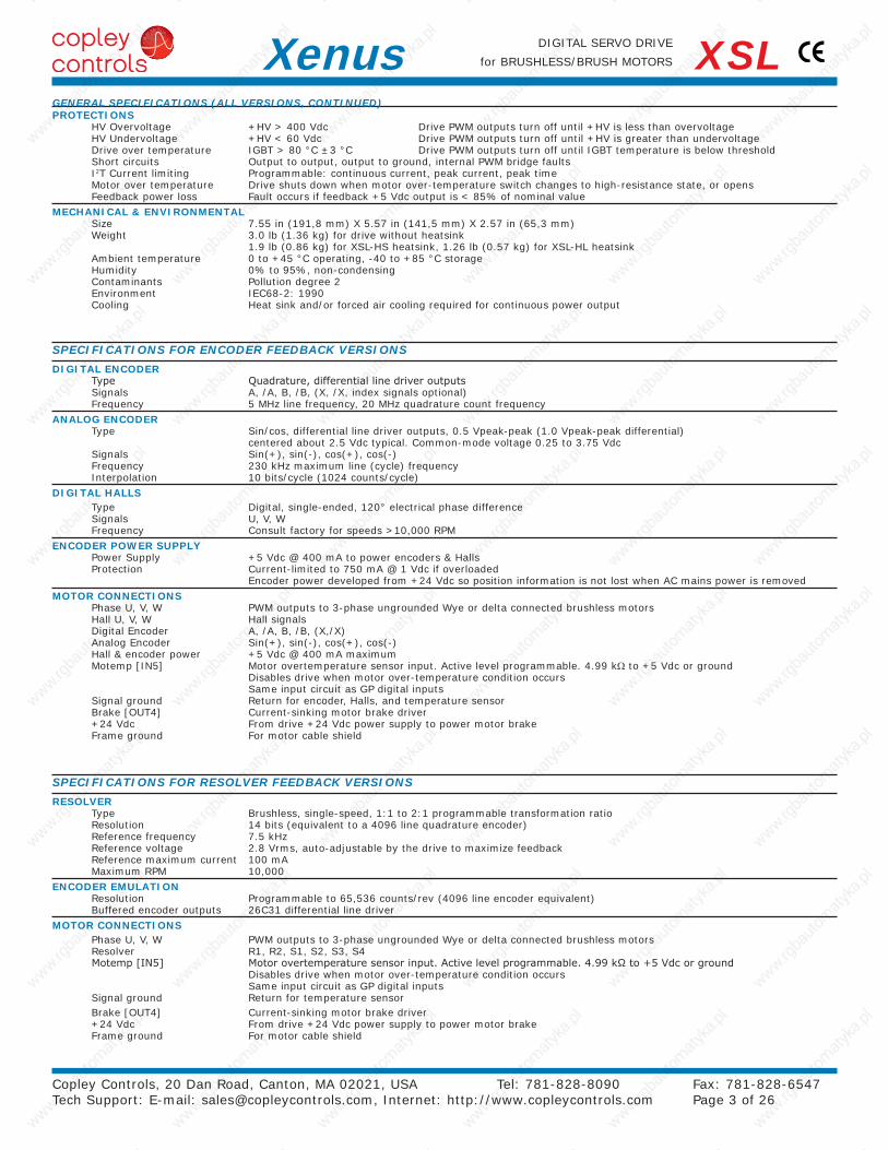
SPECIFICATIONS FOR RESOLVER FEEDBACK VERSIONS
RESOLVERType Brushless, single-speed, 1:1 to 2:1 programmable transformation ratio Resolution 14 bits (equivalent to a 4096 line quadrature encoder) Reference frequency 7.5 kHz Reference voltage 2.8 Vrms, auto-adjustable by the drive to maximize feedback Reference maximum current 100 mA Maximum RPM 10,000
ENCODER EMULATIONResolution Programmable to 65,536 counts/rev (4096 line encoder equivalent) Buffered encoder outputs 26C31 differential line driver
MOTOR CONNECTIONSPhase U, V, W PWM outputs to 3-phase ungrounded Wye or delta connected brushless motors Resolver R1, R2, S1, S2, S3, S4 Motemp [IN5] Motor overtemperature sensor input. Active level programmable. 4.99 kΩ to +5 Vdc or ground
Disables drive when motor over-temperature condition occurs Same input circuit as GP digital inputs
Signal ground Return for temperature sensorBrake [OUT4] Current-sinking motor brake driver +24 Vdc From drive +24 Vdc power supply to power motor brake Frame ground For motor cable shield
SPECIFICATIONS FOR ENCODER FEEDBACK VERSIONS
DIGITAL ENCODERType Quadrature, differential line driver outputs Signals A, /A, B, /B, (X, /X, index signals optional) Frequency 5 MHz line frequency, 20 MHz quadrature count frequency
ANALOG ENCODERType Sin/cos, differential line driver outputs, 0.5 Vpeak-peak (1.0 Vpeak-peak differential)
centered about 2.5 Vdc typical. Common-mode voltage 0.25 to 3.75 Vdc Signals Sin(+), sin(-), cos(+), cos(-) Frequency 230 kHz maximum line (cycle) frequency Interpolation 10 bits/cycle (1024 counts/cycle)
DIGITAL HALLSType Digital, single-ended, 120° electrical phase difference Signals U, V, W Frequency Consult factory for speeds >10,000 RPM
ENCODER POWER SUPPLYPower Supply +5 Vdc @ 400 mA to power encoders & Halls Protection Current-limited to 750 mA @ 1 Vdc if overloaded
Encoder power developed from +24 Vdc so position information is not lost when AC mains power is removed
MOTOR CONNECTIONSPhase U, V, W PWM outputs to 3-phase ungrounded Wye or delta connected brushless motors Hall U, V, W Hall signals Digital Encoder A, /A, B, /B, (X,/X) Analog Encoder Sin(+), sin(-), cos(+), cos(-) Hall & encoder power +5 Vdc @ 400 mA maximum Motemp [IN5] Motor overtemperature sensor input. Active level programmable. 4.99 kΩ to +5 Vdc or ground
Disables drive when motor over-temperature condition occurs Same input circuit as GP digital inputs
Signal ground Return for encoder, Halls, and temperature sensor Brake [OUT4] Current-sinking motor brake driver +24 Vdc From drive +24 Vdc power supply to power motor brake Frame ground For motor cable shield
GENERAL SPECIFICATIONS (ALL VERSIONS, CONTINUED)PROTECTIONS
HV Overvoltage +HV > 400 Vdc Drive PWM outputs turn off until +HV is less than overvoltage HV Undervoltage +HV < 60 Vdc Drive PWM outputs turn off until +HV is greater than undervoltage Drive over temperature IGBT > 80 °C ±3 °C Drive PWM outputs turn off until IGBT temperature is below threshold Short circuits Output to output, output to ground, internal PWM bridge faults I2T Current limiting Programmable: continuous current, peak current, peak time Motor over temperature Drive shuts down when motor over-temperature switch changes to high-resistance state, or opens Feedback power loss Fault occurs if feedback +5 Vdc output is < 85% of nominal value
MECHANICAL & ENVIRONMENTALSize 7.55 in (191,8 mm) X 5.57 in (141,5 mm) X 2.57 in (65,3 mm) Weight 3.0 lb (1.36 kg) for drive without heatsink
1.9 lb (0.86 kg) for XSL-HS heatsink, 1.26 lb (0.57 kg) for XSL-HL heatsink Ambient temperature 0 to +45 °C operating, -40 to +85 °C storage Humidity 0% to 95%, non-condensing Contaminants Pollution degree 2 Environment IEC68-2: 1990 Cooling Heat sink and/or forced air cooling required for continuous power output
Copley Controls, 20 Dan Road, Canton, MA 02021, USA Tel: 781-828-8090 Fax: 781-828-6547 Tech Support: E-mail: [email protected], Internet: http://www.copleycontrols.com Page 4 of 26
DIGITAL SERVO DRIVE
for BRUSHLESS/BRUSH MOTORSXenus XSL
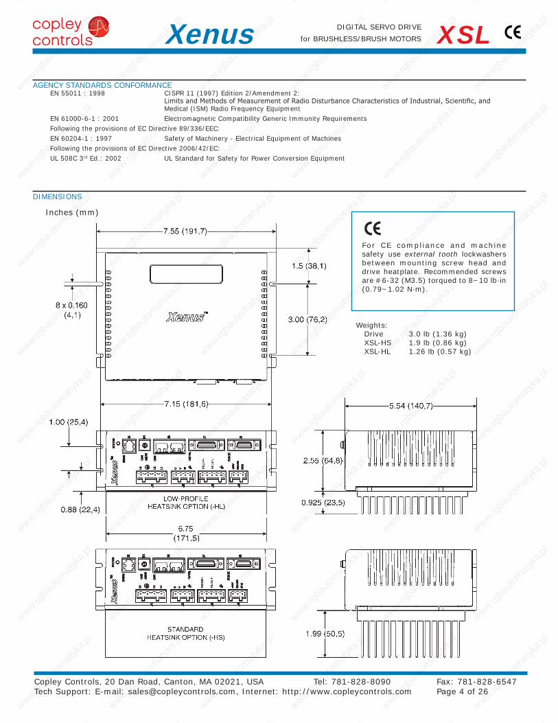
Inches (mm)
DIMENSIONS
For CE compliance and machine safety use external tooth lockwashers between mounting screw head and drive heatplate. Recommended screws are #6-32 (M3.5) torqued to 8~10 lb·in (0.79~1.02 N·m).
Weights:Drive 3.0 lb (1.36 kg) XSL-HS 1.9 lb (0.86 kg) XSL-HL 1.26 lb (0.57 kg)
AGENCY STANDARDS CONFORMANCEEN 55011 : 1998 CISPR 11 (1997) Edition 2/Amendment 2:
Limits and Methods of Measurement of Radio Disturbance Characteristics of Industrial, Scientific, and Medical (ISM) Radio Frequency Equipment
EN 61000-6-1 : 2001 Electromagnetic Compatibility Generic Immunity RequirementsFollowing the provisions of EC Directive 89/336/EEC:EN 60204-1 : 1997 Safety of Machinery - Electrical Equipment of MachinesFollowing the provisions of EC Directive 2006/42/EC:UL 508C 3rd Ed.: 2002 UL Standard for Safety for Power Conversion Equipment
Copley Controls, 20 Dan Road, Canton, MA 02021, USA Tel: 781-828-8090 Fax: 781-828-6547 Tech Support: E-mail: [email protected], Internet: http://www.copleycontrols.com Page 5 of 26
DIGITAL SERVO DRIVE
for BRUSHLESS/BRUSH MOTORSXenus XSL
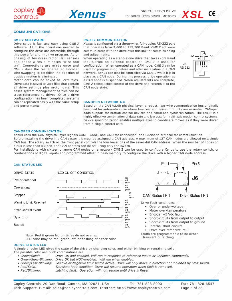
RS-232 COMMUNICATIONXenus is configured via a three-wire, full-duplex RS-232 port that operates from 9,600 to 115,200 Baud. CME 2 software communicates with the drive over this link for commissioning and adjustments.When operating as a stand-alone drive that takes command inputs from an external controller, CME 2 is used for configuration. When operated as a CAN node, CME 2 can be used for programming before and after installation in a CAN network. Xenus can also be controlled via CME 2 while it is in place as a CAN node. During this process, drive operation as a CAN node is suspended. When adjustments are complete, CME 2 relinquishes control of the drive and returns it to the CAN node state.
CANOPEN COMMUNICATIONXenus uses the CAN physical layer signals CANH, CANL, and GND for connection, and CANopen protocol for communication. Before installing the drive in a CAN system, it must be assigned a CAN address. A maximum of 127 CAN nodes are allowed on a single CAN bus. The rotary switch on the front panel controls the four lower bits of the seven-bit CAN address. When the number of nodes on a bus is less than sixteen, the CAN address can be set using only the switch.For installations with sixteen or more CAN nodes on a network CME 2 can be used to configure Xenus to use the rotary switch, or combinations of digital inputs and programmed offset in flash memory to configure the drive with a higher CAN node address.
CANOPEN NETWORKINGBased on the CAN V2.0b physical layer, a robust, two-wire communication bus originally designed for automotive use where low-cost and noise-immunity are essential, CANopen adds support for motion-control devices and command synchronization. The result is a highly effective combination of data-rate and low cost for multi-axis motion control systems. Device synchronization enables multiple axes to coordinate moves as if they were driven from a single control card.
CME 2 SOFTWAREDrive setup is fast and easy using CME 2 software. All of the operations needed to configure the drive are accessible through this powerful and intuitive program. Auto-phasing of brushless motor Hall sensors and phase wires eliminates “wire and try”. Connections are made once and CME 2 does the rest thereafter. Encoder wire swapping to establish the direction of positive motion is eliminated.Motor data can be saved as .ccm files. Drive data is saved as .ccx files that contain all drive settings plus motor data. This eases system management as files can be cross-referenced to drives. Once a drive configuration has been completed systems can be replicated easily with the same setup and performance.
DRIVE STATUS LEDA single bi-color LED gives the state of the drive by changing color, and either blinking or remaining solid. The possible color and blink combinations are:•Green/Solid: DriveOKandenabled.WillruninresponsetoreferenceinputsorCANopencommands.•Green/Slow-Blinking: DriveOKbutNOT-enabled.Willrunwhenenabled.•Green/Fast-Blinking: PositiveorNegativelimitswitchactive.Drivewillonlymoveindirectionnotinhibitedbylimitswitch.•Red/Solid: Transientfaultcondition.Drivewillresumeoperationwhenfaultisremoved.•Red/Blinking: Latchingfault.OperationwillnotresumeuntildriveisReset
Note: Red & green led on-times do not overlap. LED color may be red, green, off, or flashing of either color.
COMMUNICATIONS
CAN STATUS LED
Drive Fault conditions:• Over or under-voltage• Motor over-temperature• Encoder +5 Vdc fault• Short-circuits from output to output• Short-circuits from output to ground• Internal short circuits• Drive over-temperature
Faults are programmable to be either transient or latching
Xenus
24
25
23
1
+
5.0k
5.0k37.4k
Frame Ground
Vref
J7D/A
F.G.
37.4k±10V
Sgnd
-
Copley Controls, 20 Dan Road, Canton, MA 02021, USA Tel: 781-828-8090 Fax: 781-828-6547 Tech Support: E-mail: [email protected], Internet: http://www.copleycontrols.com Page 6 of 26
DIGITAL SERVO DRIVE
for BRUSHLESS/BRUSH MOTORSXenus XSL
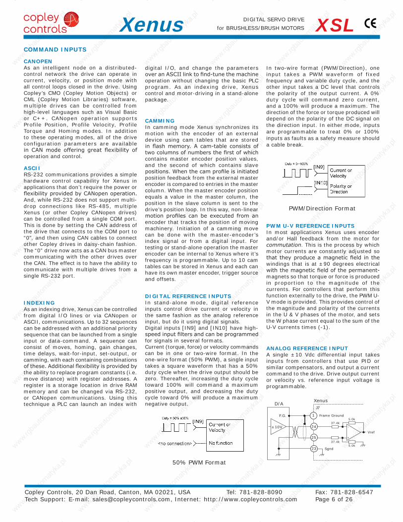
DIGITAL REFERENCE INPUTSIn stand-alone mode, digital reference inputs control drive current or velocity in the same fashion as the analog reference input, but do it using digital signals.Digital inputs [IN9] and [IN10] have high-speed input filters and can be programmed for signals in several formats.Current (torque, force) or velocity commands can be in one or two-wire format. In the one-wire format (50% PWM), a single input takes a square waveform that has a 50% duty cycle when the drive output should be zero. Thereafter, increasing the duty cycle toward 100% will command a maximum positive output, and decreasing the duty cycle toward 0% will produce a maximum negative output.
PWM/Direction Format
50% PWM Format
ANALOG REFERENCE INPUTA single ±10 Vdc differential input takes inputs from controllers that use PID or similar compensators, and output a current command to the drive. Drive output current or velocity vs. reference input voltage is programmable.
CANOPENAs an intelligent node on a distributed-control network the drive can operate in current, velocity, or position mode with all control loops closed in the drive. Using Copley’s CMO (Copley Motion Objects) or CML (Copley Motion Libraries) software, multiple drives can be controlled from high-level languages such as Visual Basic or C++. CANopen operation supports Profile Position, Profile Velocity, Profile Torque and Homing modes. In addition to these operating modes, all of the drive configuration parameters are available in CAN mode offering great flexibility of operation and control.
In two-wire format (PWM/Direction), one input takes a PWM waveform of fixed frequency and variable duty cycle, and the other input takes a DC level that controls the polarity of the output current. A 0% duty cycle will command zero current, and a 100% will produce a maximum. The direction of the force or torque produced will depend on the polarity of the DC signal on the direction input. In either mode, inputs are programmable to treat 0% or 100% inputs as faults as a safety measure should a cable break.
ASCIIRS-232 communications provides a simple hardware control capability for Xenus in applications that don’t require the power or flexibility provided by CANopen operation. And, while RS-232 does not support multi-drop connections like RS-485, multiple Xenus (or other Copley CANopen drives) can be controlled from a single COM port. This is done by setting the CAN address of the drive that connects to the COM port to “0”, and then using CAN cables to connect other Copley drives in daisy-chain fashion. The “0” drive now acts as a CAN bus master communicating with the other drives over the CAN. The effect is to have the ability to communicate with multiple drives from a single RS-232 port.
INDEXINGAs an indexing drive, Xenus can be controlled from digital I/O lines or via CANopen or ASCII, communications. Up to 32 sequences can be addressed with an additional priority sequence that can be launched from a single input or data-command. A sequence can consist of moves, homing, gain changes, time delays, wait-for-input, set-output, or camming, with each containing combinations of these. Additional flexibility is provided by the ability to replace program constants (i.e. move distance) with register addresses. A register is a storage location in drive RAM memory and can be changed via RS-232, or CANopen communications. Using this technique a PLC can launch an index with
digital I/O, and change the parameters over an ASCII link to find-tune the machine operation without changing the basic PLC program. As an indexing drive, Xenus control and motor-driving in a stand-alone package.
COMMAND INPUTS
CAMMINGIn camming mode Xenus synchronizes its motion with the encoder of an external device using cam tables that are stored in flash memory. A cam-table consists of two columns of numbers the first of which contains master encoder position values, and the second of which contains slave positions. When the cam profile is initiated position feedback from the external master encoder is compared to entries in the master column. When the master encoder position equals a value in the master column, the position in the slave column is sent to the drive’s position loop. In this way, non-linear motion profiles can be executed from an encoder that tracks the position of moving machinery. Initiation of a camming move can be done with the master-encoder’s index signal or from a digital input. For testing or stand-alone operation the master encoder can be internal to Xenus where it’s frequency is programmable. Up to 10 cam tables can be stored in Xenus and each can have its own master encoder, trigger source and offsets.
PWM U-V REFERENCE INPUTSIn most applications Xenus uses encoder and/or Hall feedback from the motor for commutation. This is the process by which motor currents are constantly adjusted so that they produce a magnetic field in the windings that is at ±90 degrees electrical with the magnetic field of the permanent-magnets so that torque or force is produced in proportion to the magnitude of the currents. For controllers that perform this function externally to the drive, the PWM U-V mode is provided. This provides control of the magnitude and polarity of the currents in the U & V phases of the motor, and sets the W phase current equal to the sum of the U-V currents times (-1).
24VDC MAX
12VDC MAX
24VDC MAX
12VDC MAX (*24VDC)
Copley Controls, 20 Dan Road, Canton, MA 02021, USA Tel: 781-828-8090 Fax: 781-828-6547 Tech Support: E-mail: [email protected], Internet: http://www.copleycontrols.com Page 7 of 26
DIGITAL SERVO DRIVE
for BRUSHLESS/BRUSH MOTORSXenus XSL
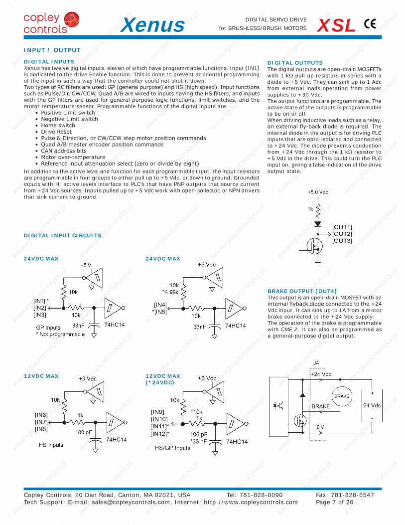
DIGITAL OUTPUTSThe digital outputs are open-drain MOSFETs with 1 kΩ pull-up resistors in series with a diode to +5 Vdc. They can sink up to 1 Adc from external loads operating from power supplies to +30 Vdc.The output functions are programmable. The active state of the outputs is programmable to be on or off.When driving inductive loads such as a relay, an external fly-back diode is required. The internal diode in the output is for driving PLC inputs that are opto-isolated and connected to +24 Vdc. The diode prevents conduction from +24 Vdc through the 1 kΩ resistor to +5 Vdc in the drive. This could turn the PLC input on, giving a false indication of the drive output state.
DIGITAL INPUTSXenus has twelve digital inputs, eleven of which have programmable functions. Input [IN1] is dedicated to the drive Enable function. This is done to prevent accidental programming of the input in such a way that the controller could not shut it down.Two types of RC filters are used: GP (general purpose) and HS (high speed). Input functions such as Pulse/Dir, CW/CCW, Quad A/B are wired to inputs having the HS filters, and inputs with the GP filters are used for general purpose logic functions, limit switches, and the motor temperature sensor. Programmable functions of the digital inputs are:
• Positive Limit switch• Negative Limit switch• Home switch• Drive Reset• Pulse & Direction, or CW/CCW step motor position commands• Quad A/B master encoder position commands• CAN address bits• Motor over-temperature• Reference input attenuation select (zero or divide by eight)
In addition to the active level and function for each programmable input, the input resistors are programmable in four groups to either pull up to +5 Vdc, or down to ground. Grounded inputs with HI active levels interface to PLC’s that have PNP outputs that source current from +24 Vdc sources. Inputs pulled up to +5 Vdc work with open-collector, or NPN drivers that sink current to ground.
BRAKE OUTPUT [OUT4]This output is an open-drain MOSFET with an internal flyback diode connected to the +24 Vdc input. It can sink up to 1A from a motor brake connected to the +24 Vdc supply.The operation of the brake is programmable with CME 2. It can also be programmed as a general-purpose digital output.
DIGITAL INPUT CIRCUITS
INPUT / OUTPUT
Sin/Cos Encoder Signals Vdd = Encoder supply voltageVcm = Common-Mode Voltage
Copley Controls, 20 Dan Road, Canton, MA 02021, USA Tel: 781-828-8090 Fax: 781-828-6547 Tech Support: E-mail: [email protected], Internet: http://www.copleycontrols.com Page 8 of 26
DIGITAL SERVO DRIVE
for BRUSHLESS/BRUSH MOTORSXenus XSL
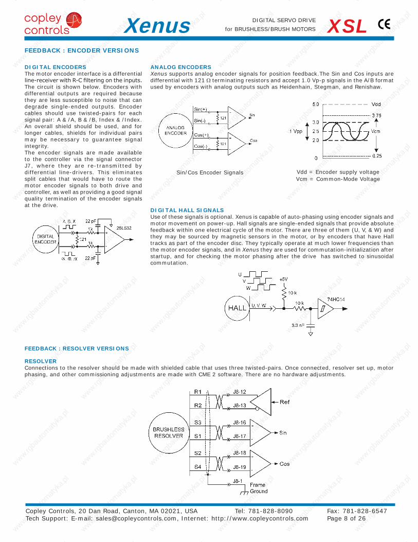
DIGITAL ENCODERSThe motor encoder interface is a differential line-receiver with R-C filtering on the inputs. The circuit is shown below. Encoders with differential outputs are required because they are less susceptible to noise that can degrade single-ended outputs. Encoder cables should use twisted-pairs for each signal pair: A & /A, B & /B, Index & /Index. An overall shield should be used, and for longer cables, shields for individual pairs may be necessary to guarantee signal integrity.The encoder signals are made available to the controller via the signal connector J7, where they are re-transmitted by differential line-drivers. This eliminates split cables that would have to route the motor encoder signals to both drive and controller, as well as providing a good signal quality termination of the encoder signals at the drive.
DIGITAL HALL SIGNALSUse of these signals is optional. Xenus is capable of auto-phasing using encoder signals and motor movement on power-up. Hall signals are single-ended signals that provide absolute feedback within one electrical cycle of the motor. There are three of them (U, V, & W) and they may be sourced by magnetic sensors in the motor, or by encoders that have Hall tracks as part of the encoder disc. They typically operate at much lower frequencies than the motor encoder signals, and in Xenus they are used for commutation-initialization after startup, and for checking the motor phasing after the drive has switched to sinusoidal commutation.
ANALOG ENCODERSXenus supports analog encoder signals for position feedback.The Sin and Cos inputs are differential with 121 Ω terminating resistors and accept 1.0 Vp-p signals in the A/B format used by encoders with analog outputs such as Heidenhain, Stegman, and Renishaw.
RESOLVERConnections to the resolver should be made with shielded cable that uses three twisted-pairs. Once connected, resolver set up, motor phasing, and other commissioning adjustments are made with CME 2 software. There are no hardware adjustments.
FEEDBACK : RESOLVER VERSIONS
FEEDBACK : ENCODER VERSIONS
-
+
Secondary22 pF
26CS32
2.2kEncoder Input
1k
+5V
1k
22 pF
Buffered Digital Encoder orEmulated Encoder Output
Input/OutputSelect
26CS31
Copley Controls, 20 Dan Road, Canton, MA 02021, USA Tel: 781-828-8090 Fax: 781-828-6547 Tech Support: E-mail: [email protected], Internet: http://www.copleycontrols.com Page 9 of 26
DIGITAL SERVO DRIVE
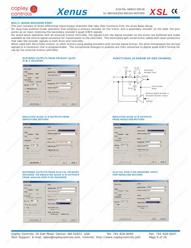
for BRUSHLESS/BRUSH MOTORSXenus XSLMULTI-MODE ENCODER PORTThis port consists of three differential input/output channels that take their functions from the drive Basic Setup.For dual-loop position-mode operation that employs a primary encoder on the motor, and a secondary encoder on the load, the port works as an input receiving the secondary encoder’s quad A/B/X signals.For stand-alone operation with an external motion controller, the signals from the digital encoder on the motor are buffered and made available at the control signal connector for transmission to the controller. This eliminates split-wired motor cables with dual connectors that take the encoder signals to both drive and controller.When used with ServoTube motors, or other motors using analog encoders with sin/cos signal format, the drive interpolates the sin/cos signals to a resolution that is programmable. The incremental changes in position are then converted to digital quad A/B/X format for use by the external motion controller.
FUNCTIONAL DIAGRAM OF ONE CHANNELBUFFERED OUTPUTS FROM PRIMARY QUAD A/B/X ENCODER
EMULATED QUAD A/B OUTPUTS FROM SERVOTUBE MOTORS
BUFFERED OUTPUTS FROM DIGITAL PRIMARY ENCODER OR EMULATED QUAD A/B OUTPUTS FROM ANALOG POSITION ENCODER
EMULATED QUAD A/B OUTPUTS FROM RESOLVER MOTORS
DIGITAL POSITION ENCODER INPUT FOR RESOLVER MOTORS
(NOTE 1)
(NOTE 1)
Copley Controls, 20 Dan Road, Canton, MA 02021, USA Tel: 781-828-8090 Fax: 781-828-6547 Tech Support: E-mail: [email protected], Internet: http://www.copleycontrols.com Page 10 of 26
DIGITAL SERVO DRIVE
for BRUSHLESS/BRUSH MOTORSXenus XSLEncoder
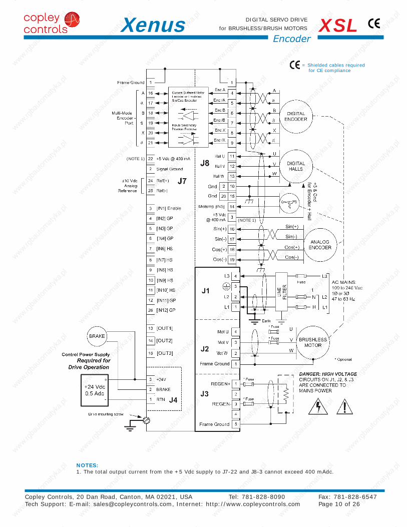
NOTES:1. The total output current from the +5 Vdc supply to J7-22 and J8-3 cannot exceed 400 mAdc.
= Shielded cables required for CE compliance
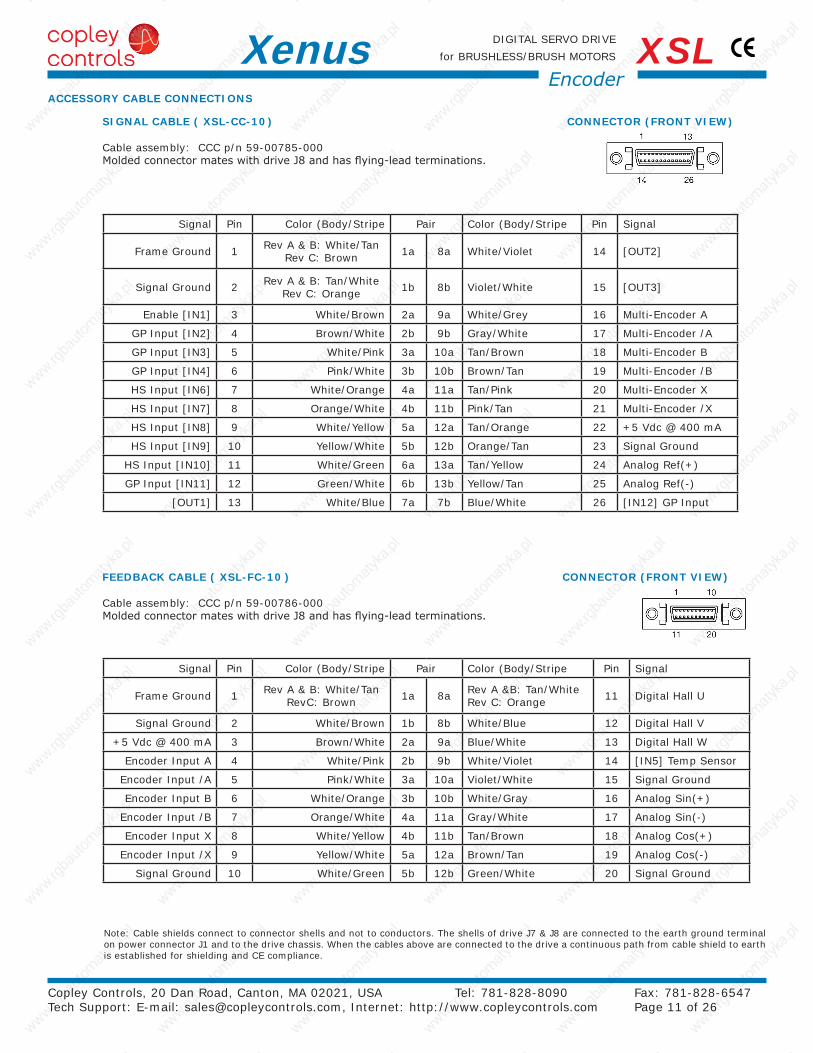
Note: Cable shields connect to connector shells and not to conductors. The shells of drive J7 & J8 are connected to the earth ground terminal on power connector J1 and to the drive chassis. When the cables above are connected to the drive a continuous path from cable shield to earth is established for shielding and CE compliance.
Copley Controls, 20 Dan Road, Canton, MA 02021, USA Tel: 781-828-8090 Fax: 781-828-6547 Tech Support: E-mail: [email protected], Internet: http://www.copleycontrols.com Page 11 of 26
DIGITAL SERVO DRIVE
for BRUSHLESS/BRUSH MOTORSXenus XSLEncoder
ACCESSORY CABLE CONNECTIONS
Signal Pin Color (Body/Stripe Pair Color (Body/Stripe Pin Signal
Frame Ground 1 Rev A & B: White/Tan Rev C: Brown 1a 8a White/Violet 14 [OUT2]
Signal Ground 2 Rev A & B: Tan/White Rev C: Orange 1b 8b Violet/White 15 [OUT3]
Enable [IN1] 3 White/Brown 2a 9a White/Grey 16 Multi-Encoder A
GP Input [IN2] 4 Brown/White 2b 9b Gray/White 17 Multi-Encoder /A
GP Input [IN3] 5 White/Pink 3a 10a Tan/Brown 18 Multi-Encoder B
GP Input [IN4] 6 Pink/White 3b 10b Brown/Tan 19 Multi-Encoder /B
HS Input [IN6] 7 White/Orange 4a 11a Tan/Pink 20 Multi-Encoder X
HS Input [IN7] 8 Orange/White 4b 11b Pink/Tan 21 Multi-Encoder /X
HS Input [IN8] 9 White/Yellow 5a 12a Tan/Orange 22 +5 Vdc @ 400 mA
HS Input [IN9] 10 Yellow/White 5b 12b Orange/Tan 23 Signal Ground
HS Input [IN10] 11 White/Green 6a 13a Tan/Yellow 24 Analog Ref(+)
GP Input [IN11] 12 Green/White 6b 13b Yellow/Tan 25 Analog Ref(-)
[OUT1] 13 White/Blue 7a 7b Blue/White 26 [IN12] GP Input
Signal Pin Color (Body/Stripe Pair Color (Body/Stripe Pin Signal
Frame Ground 1 Rev A & B: White/Tan RevC: Brown 1a 8a Rev A &B: Tan/White
Rev C: Orange 11 Digital Hall U
Signal Ground 2 White/Brown 1b 8b White/Blue 12 Digital Hall V
+5 Vdc @ 400 mA 3 Brown/White 2a 9a Blue/White 13 Digital Hall W
Encoder Input A 4 White/Pink 2b 9b White/Violet 14 [IN5] Temp Sensor
Encoder Input /A 5 Pink/White 3a 10a Violet/White 15 Signal Ground
Encoder Input B 6 White/Orange 3b 10b White/Gray 16 Analog Sin(+)
Encoder Input /B 7 Orange/White 4a 11a Gray/White 17 Analog Sin(-)
Encoder Input X 8 White/Yellow 4b 11b Tan/Brown 18 Analog Cos(+)
Encoder Input /X 9 Yellow/White 5a 12a Brown/Tan 19 Analog Cos(-)
Signal Ground 10 White/Green 5b 12b Green/White 20 Signal Ground
SIGNAL CABLE ( XSL-CC-10 ) CONNECTOR (FRONT VIEW)
Cable assembly: CCC p/n 59-00785-000 Molded connector mates with drive J8 and has flying-lead terminations.
FEEDBACK CABLE ( XSL-FC-10 ) CONNECTOR (FRONT VIEW)
Cable assembly: CCC p/n 59-00786-000 Molded connector mates with drive J8 and has flying-lead terminations.
Signal Pin
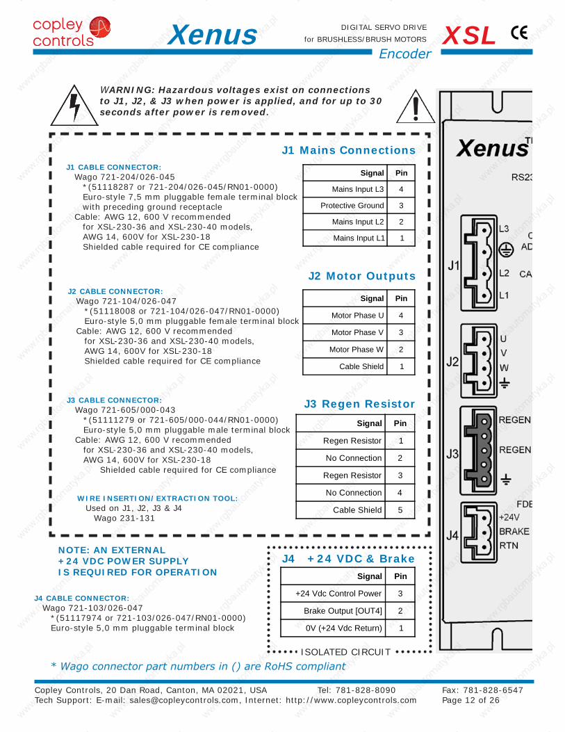
+24 Vdc Control Power 3
Brake Output [OUT4] 2
0V (+24 Vdc Return) 1
Signal Pin
Mains Input L3 4
Protective Ground 3
Mains Input L2 2
Mains Input L1 1
Signal Pin
Motor Phase U 4
Motor Phase V 3
Motor Phase W 2
Cable Shield 1
Signal Pin
Regen Resistor 1
No Connection 2
Regen Resistor 3
No Connection 4
Cable Shield 5
Copley Controls, 20 Dan Road, Canton, MA 02021, USA Tel: 781-828-8090 Fax: 781-828-6547 Tech Support: E-mail: [email protected], Internet: http://www.copleycontrols.com Page 12 of 26
DIGITAL SERVO DRIVE
for BRUSHLESS/BRUSH MOTORSXenus XSLEncoder
J1 Mains Connections
J2 Motor Outputs
J3 Regen Resistor
J4 +24 VDC & Brake
J1 CABLE CONNECTOR: Wago 721-204/026-045
*(51118287 or 721-204/026-045/RN01-0000) Euro-style 7,5 mm pluggable female terminal block with preceding ground receptacle
Cable: AWG 12, 600 V recommended for XSL-230-36 and XSL-230-40 models, AWG 14, 600V for XSL-230-18 Shielded cable required for CE compliance
J2 CABLE CONNECTOR: Wago 721-104/026-047
*(51118008 or 721-104/026-047/RN01-0000) Euro-style 5,0 mm pluggable female terminal block
Cable: AWG 12, 600 V recommended for XSL-230-36 and XSL-230-40 models, AWG 14, 600V for XSL-230-18 Shielded cable required for CE compliance
J3 CABLE CONNECTOR:Wago 721-605/000-043
*(51111279 or 721-605/000-044/RN01-0000) Euro-style 5,0 mm pluggable male terminal block
Cable: AWG 12, 600 V recommended for XSL-230-36 and XSL-230-40 models, AWG 14, 600V for XSL-230-18 Shielded cable required for CE compliance
J4 CABLE CONNECTOR:Wago 721-103/026-047
*(51117974 or 721-103/026-047/RN01-0000) Euro-style 5,0 mm pluggable terminal block
WIRE INSERTION/EXTRACTION TOOL:Used on J1, J2, J3 & J4
Wago 231-131
NOTE: AN EXTERNAL +24 VDC POWER SUPPLY IS REQUIRED FOR OPERATION
ISOLATED CIRCUIT
*Wagoconnectorpartnumbersin()areRoHScompliant
WARNING: Hazardous voltages exist on connections to J1, J2, & J3 when power is applied, and for up to 30 seconds after power is removed.
Signal Pin Signal
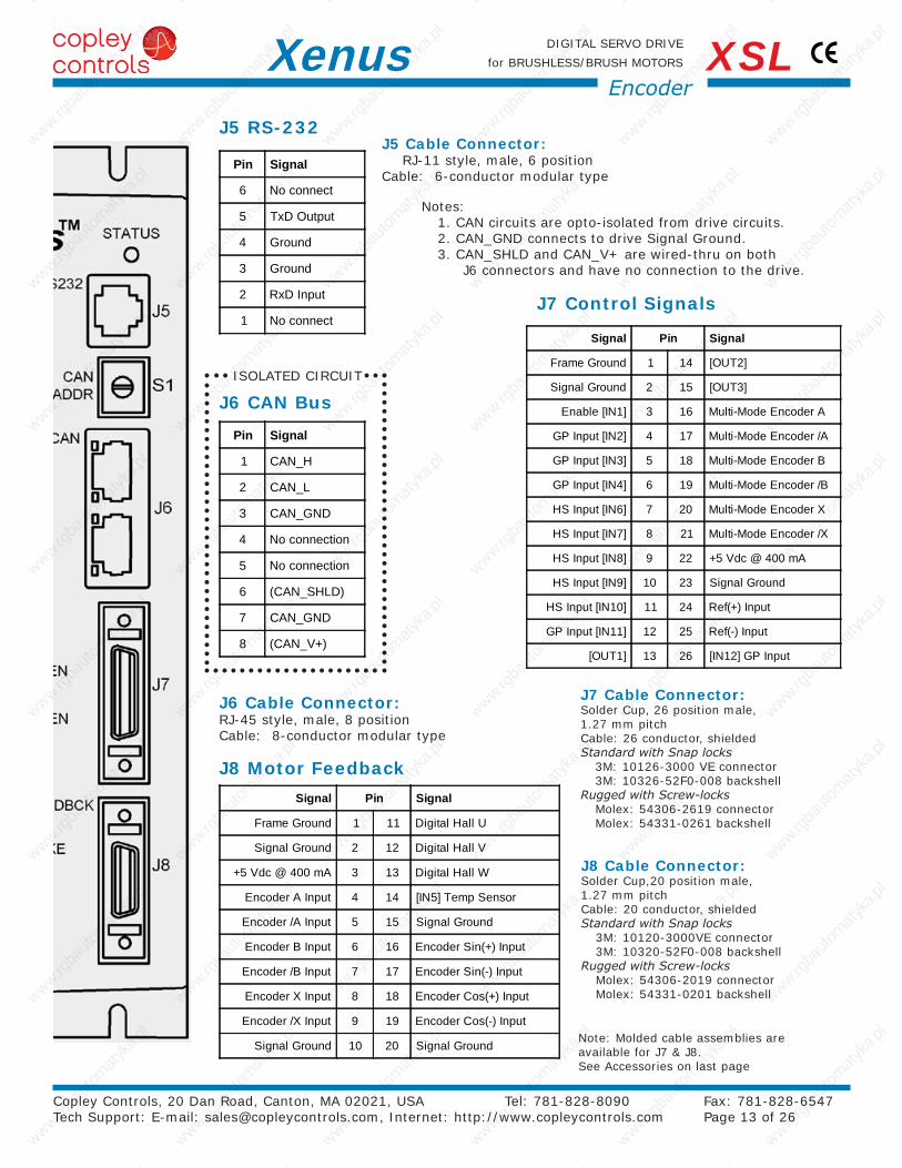
Frame Ground 1 11 Digital Hall U
Signal Ground 2 12 Digital Hall V
+5 Vdc @ 400 mA 3 13 Digital Hall W
Encoder A Input 4 14 [IN5] Temp Sensor
Encoder /A Input 5 15 Signal Ground
Encoder B Input 6 16 Encoder Sin(+) Input
Encoder /B Input 7 17 Encoder Sin(-) Input
Encoder X Input 8 18 Encoder Cos(+) Input
Encoder /X Input 9 19 Encoder Cos(-) Input
Signal Ground 10 20 Signal Ground
Signal Pin Signal
Frame Ground 1 14 [OUT2]
Signal Ground 2 15 [OUT3]
Enable [IN1] 3 16 Multi-Mode Encoder A
GP Input [IN2] 4 17 Multi-Mode Encoder /A
GP Input [IN3] 5 18 Multi-Mode Encoder B
GP Input [IN4] 6 19 Multi-Mode Encoder /B
HS Input [IN6] 7 20 Multi-Mode Encoder X
HS Input [IN7] 8 21 Multi-Mode Encoder /X
HS Input [IN8] 9 22 +5 Vdc @ 400 mA
HS Input [IN9] 10 23 Signal Ground
HS Input [IN10] 11 24 Ref(+) Input
GP Input [IN11] 12 25 Ref(-) Input
[OUT1] 13 26 [IN12] GP Input
Pin Signal
1 CAN_H
2 CAN_L
3 CAN_GND
4 No connection
5 No connection
6 (CAN_SHLD)
7 CAN_GND
8 (CAN_V+)
Pin Signal
6 No connect
5 TxD Output
4 Ground
3 Ground
2 RxD Input
1 No connect
Copley Controls, 20 Dan Road, Canton, MA 02021, USA Tel: 781-828-8090 Fax: 781-828-6547 Tech Support: E-mail: [email protected], Internet: http://www.copleycontrols.com Page 13 of 26
DIGITAL SERVO DRIVE
for BRUSHLESS/BRUSH MOTORSXenus XSLEncoder
J8 Motor Feedback
J7 Control Signals
J6 CAN Bus
J5 RS-232J5 Cable Connector: RJ-11 style, male, 6 position Cable: 6-conductor modular type
J6 Cable Connector: RJ-45 style, male, 8 position Cable: 8-conductor modular type
Notes:1. CAN circuits are opto-isolated from drive circuits. 2. CAN_GND connects to drive Signal Ground. 3. CAN_SHLD and CAN_V+ are wired-thru on both J6 connectors and have no connection to the drive.
ISOLATED CIRCUIT
J7 Cable Connector:Solder Cup, 26 position male, 1.27 mm pitch Cable: 26 conductor, shieldedStandardwithSnaplocks
3M: 10126-3000 VE connector 3M: 10326-52F0-008 backshell
RuggedwithScrew-locksMolex: 54306-2619 connector Molex: 54331-0261 backshell
J8 Cable Connector: Solder Cup,20 position male, 1.27 mm pitch Cable: 20 conductor, shieldedStandardwithSnaplocks
3M: 10120-3000VE connector 3M: 10320-52F0-008 backshell
RuggedwithScrew-locksMolex: 54306-2019 connector Molex: 54331-0201 backshell
Note: Molded cable assemblies are available for J7 & J8. See Accessories on last page
(NOTE 1)
Copley Controls, 20 Dan Road, Canton, MA 02021, USA Tel: 781-828-8090 Fax: 781-828-6547 Tech Support: E-mail: [email protected], Internet: http://www.copleycontrols.com Page 14 of 26
DIGITAL SERVO DRIVE
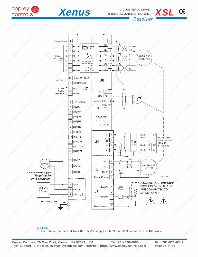
for BRUSHLESS/BRUSH MOTORSXenus XSLResolver
NOTES:1. The total output current from the +5 Vdc supply to J7-22 and J8-3 cannot exceed 400 mAdc.
Copley Controls, 20 Dan Road, Canton, MA 02021, USA Tel: 781-828-8090 Fax: 781-828-6547 Tech Support: E-mail: [email protected], Internet: http://www.copleycontrols.com Page 15 of 26
DIGITAL SERVO DRIVE
for BRUSHLESS/BRUSH MOTORSXenus XSLResolver
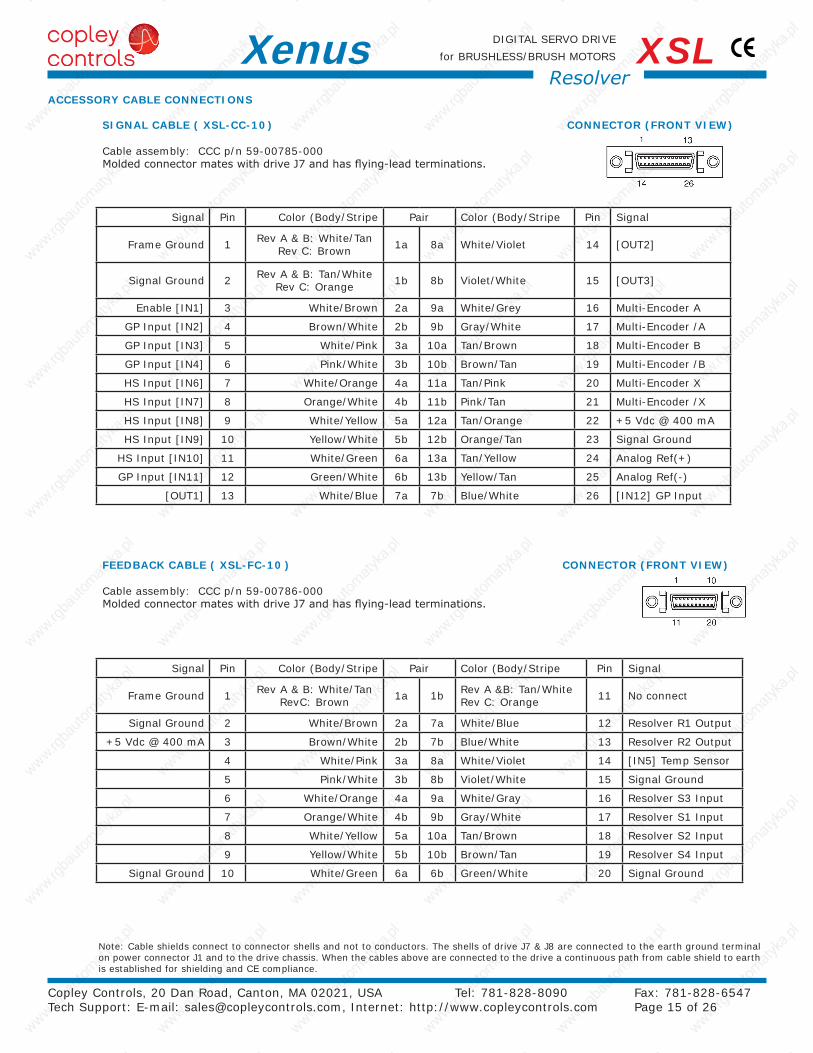
Note: Cable shields connect to connector shells and not to conductors. The shells of drive J7 & J8 are connected to the earth ground terminal on power connector J1 and to the drive chassis. When the cables above are connected to the drive a continuous path from cable shield to earth is established for shielding and CE compliance.
ACCESSORY CABLE CONNECTIONS
SIGNAL CABLE ( XSL-CC-10 ) CONNECTOR (FRONT VIEW)
Cable assembly: CCC p/n 59-00785-000 Molded connector mates with drive J7 and has flying-lead terminations.
FEEDBACK CABLE ( XSL-FC-10 ) CONNECTOR (FRONT VIEW)
Cable assembly: CCC p/n 59-00786-000 Molded connector mates with drive J7 and has flying-lead terminations.
Signal Pin Color (Body/Stripe Pair Color (Body/Stripe Pin Signal
Frame Ground 1 Rev A & B: White/Tan Rev C: Brown 1a 8a White/Violet 14 [OUT2]
Signal Ground 2 Rev A & B: Tan/White Rev C: Orange 1b 8b Violet/White 15 [OUT3]
Enable [IN1] 3 White/Brown 2a 9a White/Grey 16 Multi-Encoder A
GP Input [IN2] 4 Brown/White 2b 9b Gray/White 17 Multi-Encoder /A
GP Input [IN3] 5 White/Pink 3a 10a Tan/Brown 18 Multi-Encoder B
GP Input [IN4] 6 Pink/White 3b 10b Brown/Tan 19 Multi-Encoder /B
HS Input [IN6] 7 White/Orange 4a 11a Tan/Pink 20 Multi-Encoder X
HS Input [IN7] 8 Orange/White 4b 11b Pink/Tan 21 Multi-Encoder /X
HS Input [IN8] 9 White/Yellow 5a 12a Tan/Orange 22 +5 Vdc @ 400 mA
HS Input [IN9] 10 Yellow/White 5b 12b Orange/Tan 23 Signal Ground
HS Input [IN10] 11 White/Green 6a 13a Tan/Yellow 24 Analog Ref(+)
GP Input [IN11] 12 Green/White 6b 13b Yellow/Tan 25 Analog Ref(-)
[OUT1] 13 White/Blue 7a 7b Blue/White 26 [IN12] GP Input
Signal Pin Color (Body/Stripe Pair Color (Body/Stripe Pin Signal
Frame Ground 1 Rev A & B: White/Tan RevC: Brown 1a 1b Rev A &B: Tan/White
Rev C: Orange 11 No connect
Signal Ground 2 White/Brown 2a 7a White/Blue 12 Resolver R1 Output
+5 Vdc @ 400 mA 3 Brown/White 2b 7b Blue/White 13 Resolver R2 Output
4 White/Pink 3a 8a White/Violet 14 [IN5] Temp Sensor
5 Pink/White 3b 8b Violet/White 15 Signal Ground
6 White/Orange 4a 9a White/Gray 16 Resolver S3 Input
7 Orange/White 4b 9b Gray/White 17 Resolver S1 Input
8 White/Yellow 5a 10a Tan/Brown 18 Resolver S2 Input
9 Yellow/White 5b 10b Brown/Tan 19 Resolver S4 Input
Signal Ground 10 White/Green 6a 6b Green/White 20 Signal Ground

Signal Pin
Mains Input L3 4
Protective Ground 3
Mains Input L2 2
Mains Input L1 1
Signal Pin
Motor Phase U 4
Motor Phase V 3
Motor Phase W 2
Cable Shield 1
Signal Pin
Regen Resistor 1
No Connection 2
Regen Resistor 3
No Connection 4
Cable Shield 5
Signal Pin
+24 Vdc Control Power 3
Brake Output [OUT4] 2
0V (+24 Vdc Return) 1
Copley Controls, 20 Dan Road, Canton, MA 02021, USA Tel: 781-828-8090 Fax: 781-828-6547 Tech Support: E-mail: [email protected], Internet: http://www.copleycontrols.com Page 16 of 26
DIGITAL SERVO DRIVE
for BRUSHLESS/BRUSH MOTORSXenus XSLResolver
J1 Mains Connections
J2 Motor Outputs
J3 Regen Resistor
J4 +24 VDC & Brake
J1 CABLE CONNECTOR: Wago 721-204/026-045
*(51118287 or 721-204/026-045/RN01-0000) Euro-style 7,5 mm pluggable female terminal block with preceding ground receptacle
Cable: AWG 12, 600 V recommended for XSL-230-36 and XSL-230-40 models, AWG 14, 600V for XSL-230-18 Shielded cable required for CE compliance
J2 CABLE CONNECTOR: Wago 721-104/026-047
*(51118008 or 721-104/026-047/RN01-0000) Euro-style 5,0 mm pluggable female terminal block
Cable: AWG 12, 600 V recommended for XSL-230-36 and XSL-230-40 models, AWG 14, 600V for XSL-230-18 Shielded cable required for CE compliance
J3 CABLE CONNECTOR:Wago 721-605/000-043
*(51111279 or 721-605/000-044/RN01-0000) Euro-style 5,0 mm pluggable male terminal block
Cable: AWG 12, 600 V recommended for XSL-230-36 and XSL-230-40 models, AWG 14, 600V for XSL-230-18 Shielded cable required for CE compliance
WARNING: Hazardous voltages exist on connections to J1, J2, & J3 when power is applied, and for up to 30 seconds after power is removed.
WIRE INSERTION/EXTRACTION TOOL:Used on J1, J2, J3, & J4
Wago 231-131
ISOLATED CIRCUIT
ISOLATED CIRCUIT
*Wagoconnectorpartnumbersin()areRoHScompliant
J4 CABLE CONNECTOR:Wago 721-103/026-047
*(51117974 or 721-103/026-047/RN01-0000) Euro-style 5,0 mm pluggable terminal block
NOTE: AN EXTERNAL +24 VDC POWER SUPPLY IS REQUIRED FOR OPERATION
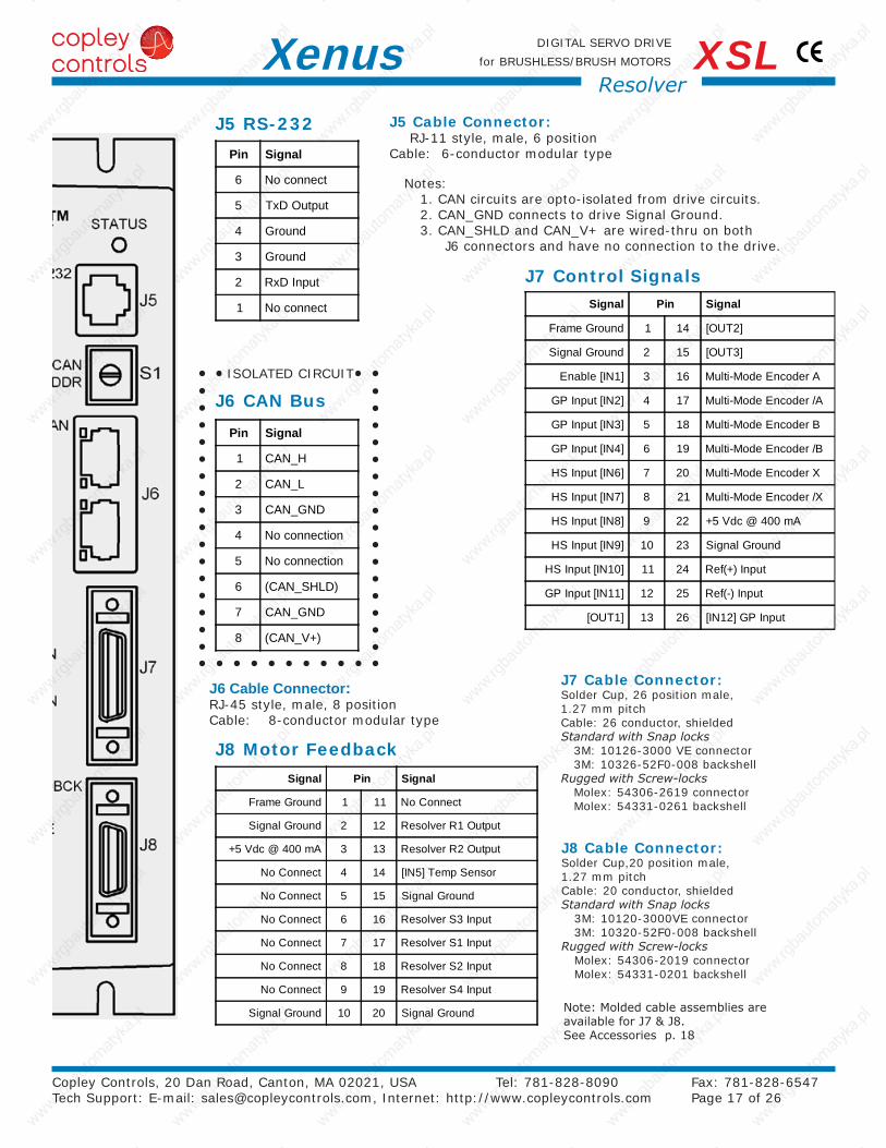
Signal Pin Signal
Frame Ground 1 14 [OUT2]
Signal Ground 2 15 [OUT3]
Enable [IN1] 3 16 Multi-Mode Encoder A
GP Input [IN2] 4 17 Multi-Mode Encoder /A
GP Input [IN3] 5 18 Multi-Mode Encoder B
GP Input [IN4] 6 19 Multi-Mode Encoder /B
HS Input [IN6] 7 20 Multi-Mode Encoder X
HS Input [IN7] 8 21 Multi-Mode Encoder /X
HS Input [IN8] 9 22 +5 Vdc @ 400 mA
HS Input [IN9] 10 23 Signal Ground
HS Input [IN10] 11 24 Ref(+) Input
GP Input [IN11] 12 25 Ref(-) Input
[OUT1] 13 26 [IN12] GP Input
Pin Signal
1 CAN_H
2 CAN_L
3 CAN_GND
4 No connection
5 No connection
6 (CAN_SHLD)
7 CAN_GND
8 (CAN_V+)
Pin Signal
6 No connect
5 TxD Output
4 Ground
3 Ground
2 RxD Input
1 No connect
Signal Pin Signal
Frame Ground 1 11 No Connect
Signal Ground 2 12 Resolver R1 Output
+5 Vdc @ 400 mA 3 13 Resolver R2 Output
No Connect 4 14 [IN5] Temp Sensor
No Connect 5 15 Signal Ground
No Connect 6 16 Resolver S3 Input
No Connect 7 17 Resolver S1 Input
No Connect 8 18 Resolver S2 Input
No Connect 9 19 Resolver S4 Input
Signal Ground 10 20 Signal Ground
Copley Controls, 20 Dan Road, Canton, MA 02021, USA Tel: 781-828-8090 Fax: 781-828-6547 Tech Support: E-mail: [email protected], Internet: http://www.copleycontrols.com Page 17 of 26
DIGITAL SERVO DRIVE
for BRUSHLESS/BRUSH MOTORSXenus XSLResolver
J8 Motor Feedback
J7 Control Signals
J6 CAN Bus
J5 RS-232
ISOLATED CIRCUIT
Notes:1. CAN circuits are opto-isolated from drive circuits. 2. CAN_GND connects to drive Signal Ground. 3. CAN_SHLD and CAN_V+ are wired-thru on both
J6 connectors and have no connection to the drive.
J5 Cable Connector: RJ-11 style, male, 6 position Cable: 6-conductor modular type
J6 Cable Connector:RJ-45 style, male, 8 position Cable: 8-conductor modular type
Note: Molded cable assemblies are available for J7 & J8. See Accessories p. 18
J7 Cable Connector:Solder Cup, 26 position male, 1.27 mm pitch Cable: 26 conductor, shieldedStandardwithSnaplocks
3M: 10126-3000 VE connector 3M: 10326-52F0-008 backshell
RuggedwithScrew-locksMolex: 54306-2619 connector Molex: 54331-0261 backshell
J8 Cable Connector: Solder Cup,20 position male, 1.27 mm pitch Cable: 20 conductor, shieldedStandardwithSnaplocks
3M: 10120-3000VE connector 3M: 10320-52F0-008 backshell
RuggedwithScrew-locksMolex: 54306-2019 connector Molex: 54331-0201 backshell
+24VDC
LOGIC&
SIGNALPOWER
RTN
PWMINVERTER
L1
CONTROLLOGIC
MAINSL3
SIGNAL GND
+5 Vdc
U
V
W
MOTOR
HALLS
ENCODER
CASE
DC BUSS(+)
DC BUSS(-)
L2
DRIVECHASSIS
CONTROLSYSTEM
ENABLE [IN1]
SIGNAL GND
SIGNAL GND
SHIELD
J8J7
J1
J2
FRAME(SAFETY)GROUND
CONTROLSIGNAL
GROUND
~
~ -
+
~+
REGEN(-) REGEN(+)
SHIELD
BRAKE
+24 Vdc
+24 VdcGROUND
J3
J4
1760 µF
DC/DCCntrl
DC/DCConverter +5 Vdc @
400mA
PWMSTAGE
CONTROLPOWER
+5 Vdc
BRAKE
Chassis ground
+5 Vdc
CANBUS
POWER
OPTICALISOLATOR
CAN BUS
ISOLATIONBARRIERS
20
40
60
80
100
120
240220200180160140120100
Energy Absorption vs.Mains Voltage
Mains Voltage (Vac)
Ener
gy
Ab
sorp
tio
n (
W·s
)
Copley Controls, 20 Dan Road, Canton, MA 02021, USA Tel: 781-828-8090 Fax: 781-828-6547 Tech Support: E-mail: [email protected], Internet: http://www.copleycontrols.com Page 18 of 26
DIGITAL SERVO DRIVE
for BRUSHLESS/BRUSH MOTORSXenus XSL
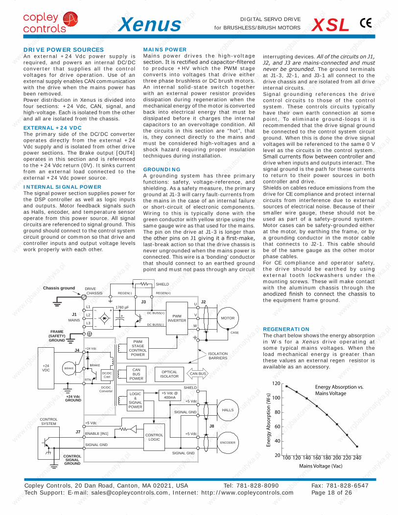
GROUNDINGA grounding system has three primary functions: safety, voltage-reference, and shielding. As a safety measure, the primary ground at J1-3 will carry fault-currents from the mains in the case of an internal failure or short-circuit of electronic components. Wiring to this is typically done with the green conductor with yellow stripe using the same gauge wire as that used for the mains. The pin on the drive at J1-3 is longer than the other pins on J1 giving it a first-make, last-break action so that the drive chassis is never ungrounded when the mains power is connected. This wire is a ‘bonding’ conductor that should connect to an earthed ground point and must not pass through any circuit
interrupting devices. AllofthecircuitsonJ1,J2,andJ3aremains-connectedandmustneverbegrounded. The ground terminals at J1-3, J2-1, and J3-1 all connect to the drive chassis and are isolated from all drive internal circuits.Signal grounding references the drive control circuits to those of the control system. These controls circuits typically have their own earth connection at some point. To eliminate ground-loops it is recommended that the drive signal ground be connected to the control system circuit ground. When this is done the drive signal voltages will be referenced to the same 0 V level as the circuits in the control system. Small currents flow between controller and drive when inputs and outputs interact. The signal ground is the path for these currents to return to their power sources in both controller and drive.Shields on cables reduce emissions from the drive for CE compliance and protect internal circuits from interference due to external sources of electrical noise. Because of their smaller wire gauge, these should not be used as part of a safety-ground system. Motor cases can be safety-grounded either at the motor, by earthing the frame, or by a grounding conductor in the motor cable that connects to J2-1. This cable should be of the same gauge as the other motor phase cables.For CE compliance and operator safety, the drive should be earthed by using external tooth lockwashers under the mounting screws. These will make contact with the aluminum chassis through the anodized finish to connect the chassis to the equipment frame ground.
DRIVE POWER SOURCESAn external +24 Vdc power supply is required, and powers an internal DC/DC converter that supplies all the control voltages for drive operation. Use of an external supply enables CAN communication with the drive when the mains power has been removed.Power distribution in Xenus is divided into four sections: +24 Vdc, CAN, signal, and high-voltage. Each is isolated from the other and all are isolated from the chassis.
EXTERNAL +24 VDCThe primary side of the DC/DC converter operates directly from the external +24 Vdc supply and is isolated from other drive power sections. The Brake output [OUT4] operates in this section and is referenced to the +24 Vdc return (0V). It sinks current from an external load connected to the external +24 Vdc power source.
INTERNAL SIGNAL POWERThe signal power section supplies power for the DSP controller as well as logic inputs and outputs. Motor feedback signals such as Halls, encoder, and temperature sensor operate from this power source. All signal circuits are referenced to signal ground. This ground should connect to the control system circuit ground or common so that drive and controller inputs and output voltage levels work properly with each other.
MAINS POWERMains power drives the high-voltage section. It is rectified and capacitor-filtered to produce +HV which the PWM stage converts into voltages that drive either three phase brushless or DC brush motors. An internal solid-state switch together with an external power resistor provides dissipation during regeneration when the mechanical energy of the motor is converted back into electrical energy that must be dissipated before it charges the internal capacitors to an overvoltage condition. All the circuits in this section are “hot”, that is, they connect directly to the mains and must be considered high-voltages and a shock hazard requiring proper insulation techniques during installation.
REGENERATIONThe chart below shows the energy absorption in W·s for a Xenus drive operating at some typical mains voltages. When the load mechanical energy is greater than these values an external regen resistor is available as an accessory.
CANCARD
COM1COM2COMx
J6
J8
J7
J5
(1)
PART NUMBER DESCRIPTION
XSL-230-18 Xenus XSL Servodrive 6/18 A
XSL-230-36 Xenus XSL Servodrive 12/36 A
XSL-230-40 Xenus XSL Servodrive 20/40 A
XSL-NK CANopen Network Kit
XSL-CK Xenus Solder-Cup Connector Kit
XSL-CA Xenus Molded-Cable Connector Kit
CME2 CME 2 Configuration Software CD
SER-CK CME 2 RS-232 Cable Kit
XSL-HS Heatsink, Standard (Optional)
XSL-HL Heatsink, Low-Profile (Optional)
XTL-RA-03 Regen resistor, 30 Ω (Optional)
XTL-RA-04 Regen resistor, 10 Ω (Optional)
Add -R to Xenus part number for resolver feedback model
Copley Controls, 20 Dan Road, Canton, MA 02021, USA Tel: 781-828-8090 Fax: 781-828-6547 Tech Support: E-mail: [email protected], Internet: http://www.copleycontrols.com Page 19 of 26
DIGITAL SERVO DRIVE
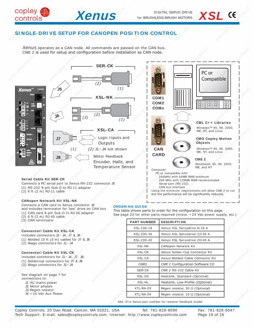
for BRUSHLESS/BRUSH MOTORSXenus XSLSINGLE-DRIVE SETUP FOR CANOPEN POSITION CONTROL
See diagram on page 7 for connections to:
J1 AC mains power J2 Motor phases J3 Regen resistor J4 +24 Vdc Aux Power
CANopen Network Kit XSL-NKConnects a CAN card to Xenus connector J6 and includes terminator for ‘last’ drive on CAN bus(1) CAN card 9-pin Sub-D to RJ-45 adapter (2) 6 ft (2 m) RJ-45 cable (3) CAN terminator
Connector/Cable Kit XSL-CAIncludes connectors J1~J4, J7 & J8:(1) Molded 10 ft (3 m) cables for J7 & J8 (2) Wago connectors for J1~J4
Logic Inputs andOutputs
Motor FeedbackEncoder, Halls, andTemperature Sensor
Xenus operates as a CAN node. All commands are passed on the CAN bus.CME 2 is used for setup and configuration before installation as CAN node.
Serial Cable Kit SER-CKConnects a PC serial port to Xenus RX-232 connector J5(1) RS-232 9-pin Sub-D to RJ-11 adapter (2) 6 ft (2 m) RJ-11 cable
Connector/Cable Kit XSL-CKIncludes connectors for J1~J4, J7, J8:(1) Soldercup connectors for J7 & J8 (2) Wago connectors for J1~J4
(2) J1~J4 not shown
CML C++ Libraries
CME 2
Windows™ 95, 98, 2000, ME, NT, and Linux
Windows® 95, 98, 2000, ME, and NT
Computer:PC or compatible with 166MHz with 64MB RAM minimum 266 MHz with 128MB RAM recommended Serial port (RS-232) CAN bus interface
Using the minimum requirements will allow CME 2 to run but the performance will be significantly reduced.
CMO Copley Motion Objects
Windows™ 95, 98, 2000, ME, NT, and Linux
XSL-NK
XSL-CA
SER-CK
(1)(2)
(1)(2)
(3)
ORDERING GUIDEThis table shows parts to order for the configuration on this pageSee page 23 for other parts required (motor, +24 Vdc power supply, etc.)
J6
J6
J6
PART NUMBER DESCRIPTION
XSL-230-18 Xenus XSL Servodrive 6/18 A
XSL-230-36 Xenus XSL Servodrive 12/36 A
XSL-230-40 Xenus XSL Servodrive 20/40 A
XSL-NK CANopen Network Kit
XSL-NC-10 CAN Network Cable,10 ft (3 m)
XSL-NC-01 CAN Network Cable,1 ft (0.3 m)
XSL-CK Xenus Solder-Cup Connector Kit
XSL-CA Xenus Molded-Cable Connector Kit
CME2 CME 2 Configuration Software CD
SER-CK CME 2 RS-232 Cable Kit
XSL-HS Heatsink, Standard (Optional)
XSL-HL Heatsink, Low-Profile (Optional)
XTL-RA-03 Regen resistor, 30 Ω (Optional)
XTL-RA-04 Regen resistor, 10 Ω (Optional)
Add -R to Xenus part number for resolver feedback model
Copley Controls, 20 Dan Road, Canton, MA 02021, USA Tel: 781-828-8090 Fax: 781-828-6547 Tech Support: E-mail: [email protected], Internet: http://www.copleycontrols.com Page 20 of 26
DIGITAL SERVO DRIVE
for BRUSHLESS/BRUSH MOTORSXenus XSL
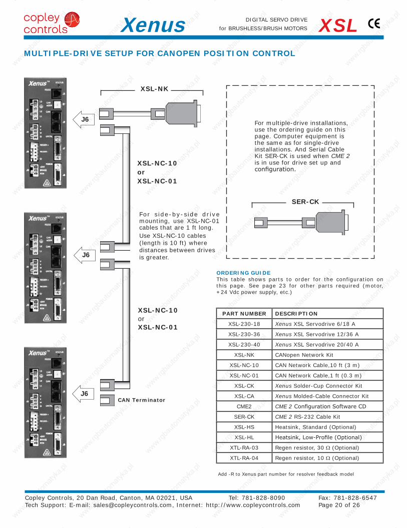
For multiple-drive installations, use the ordering guide on this page. Computer equipment is the same as for single-drive installations. And Serial Cable Kit SER-CK is used when CME 2 is in use for drive set up and configuration.
For side-by-side drive mounting, use XSL-NC-01 cables that are 1 ft long.Use XSL-NC-10 cables (length is 10 ft) where distances between drives is greater.
MULTIPLE-DRIVE SETUP FOR CANOPEN POSITION CONTROL
XSL-NC-10orXSL-NC-01
XSL-NK
CAN Terminator
XSL-NC-10orXSL-NC-01
SER-CK
ORDERING GUIDEThis table shows parts to order for the configuration on this page. See page 23 for other parts required (motor,+24 Vdc power supply, etc.)
J5
J8
J7 MotionController
PART NUMBER DESCRIPTION
XSL-230-18 Xenus XSL Servodrive 6/18 A
XSL-230-36 Xenus XSL Servodrive 12/36 A
XSL-230-40 Xenus XSL Servodrive 20/40 A
XSL-CK Xenus Solder-Cup Connector Kit
XSL-CA Xenus Molded-Cable Connector Kit
CME2 CME 2 Configuration Software CD
SER-CK CME 2 RS-232 Cable Kit
XSL-HS Heatsink, Standard (Optional)
XSL-HL Heatsink, Low-Profile (Optional)
XTL-RA-03 Regen resistor, 30 Ω (Optional)
XTL-RA-04 Regen resistor, 10 Ω (Optional)
Add -R to Xenus part number for resolver feedback model
Copley Controls, 20 Dan Road, Canton, MA 02021, USA Tel: 781-828-8090 Fax: 781-828-6547 Tech Support: E-mail: [email protected], Internet: http://www.copleycontrols.com Page 21 of 26
DIGITAL SERVO DRIVE
for BRUSHLESS/BRUSH MOTORSXenus XSLSTAND-ALONE OPERATION
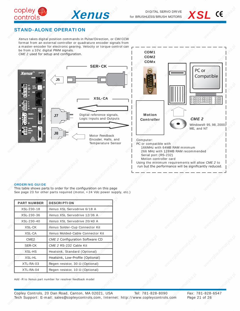
Computer:PC or compatible with 166MHz with 64MB RAM minimum 266 MHz with 128MB RAM recommended Serial port (RS-232) Motion controller cardUsing the minimum requirements will allow CME 2 to run but the performance will be significantly reduced.
Xenus takes digital position commands in Pulse/Direction, or CW/CCW format from an external controller or quadrature encoder signals from a master-encoder for electronic gearing. Velocity or torque control can be from ±10V, digital PWM signals.CME 2 used for setup and configuration.
Digital reference signals, Logic Inputs and Outputs
Motor FeedbackEncoder, Halls, andTemperature Sensor
ORDERING GUIDEThis table shows parts to order for the configuration on this pageSee page 23 for other parts required (motor, +24 Vdc power supply, etc.)
COM1COM2COMx
CME 2Windows® 95, 98, 2000,ME, and NT
SER-CK
XSL-CA
Heat-sink
AC LineFilter
Fuses
RegenResistor
XTL-RA-03XTL-RA-04
Brushless Servo Motor with Encoder (digital or analog)Digital Halls (optional)orResolverThermal sensor (optional)
DC Brush Servo Motor withEncoder (digital or analog)orResolverThermal sensor
+24 VdcPower Supply
Copley Controls, 20 Dan Road, Canton, MA 02021, USA Tel: 781-828-8090 Fax: 781-828-6547 Tech Support: E-mail: [email protected], Internet: http://www.copleycontrols.com Page 22 of 26
DIGITAL SERVO DRIVE
for BRUSHLESS/BRUSH MOTORSXenus XSL
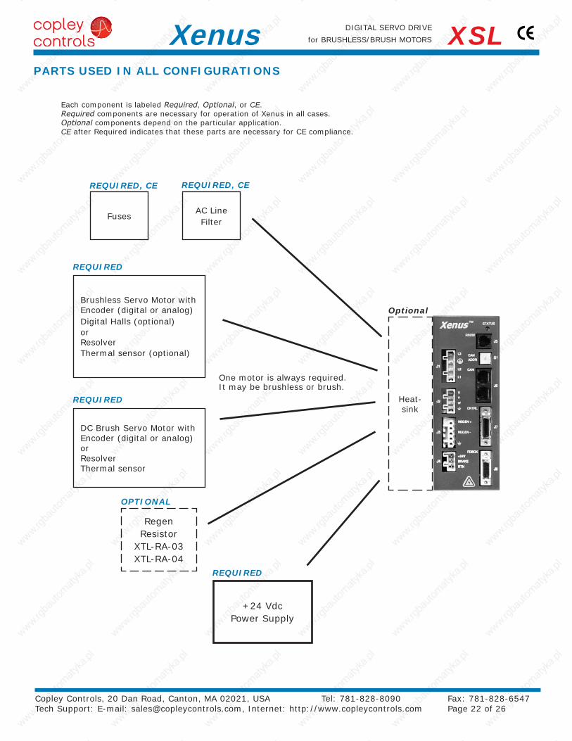
Each component is labeled Required, Optional, or CE.Required components are necessary for operation of Xenus in all cases.Optional components depend on the particular application.CE after Required indicates that these parts are necessary for CE compliance.
Optional
REQUIRED, CEREQUIRED, CE
REQUIRED
One motor is always required. It may be brushless or brush.
PARTS USED IN ALL CONFIGURATIONS
REQUIRED
REQUIRED
OPTIONAL
Edge Filter
RS-232
CME 2ASCII
Control
CANMaster
CANNode(s)
+24 VdcPowerSupply
Motor
Encoder Resolver
Line Filter
RegenResistor
Controller or
PLC
AC Mains100~240 Vac
47~63 Hz1 or 3 ph.
(Optional)
(Optional)
Copley Controls, 20 Dan Road, Canton, MA 02021, USA Tel: 781-828-8090 Fax: 781-828-6547 Tech Support: E-mail: [email protected], Internet: http://www.copleycontrols.com Page 23 of 26
DIGITAL SERVO DRIVE
for BRUSHLESS/BRUSH MOTORSXenus XSLINSTALLATION
NEW FEATURES
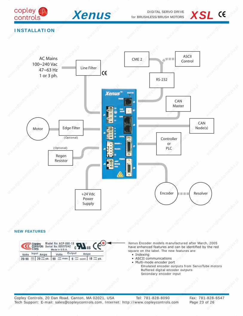
Xenus Encoder models manufactured after March, 2005 have enhanced features and can be identified by the red square on the label. The new features are:
• Indexing • ASCII communications • Multi-mode encoder port Emulated encoder outputs from ServoTube motors Buffered digital encoder outputs Secondary encoder input
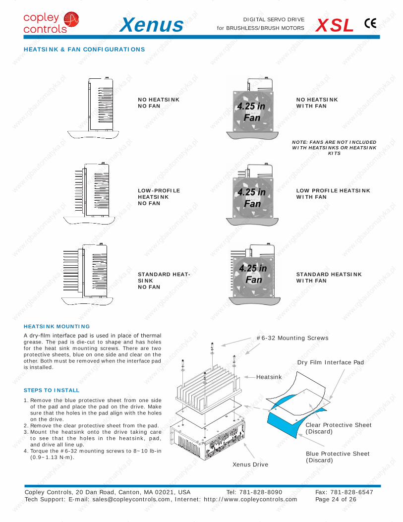
NOTE: FANS ARE NOT INCLUDED WITH HEATSINKS OR HEATSINK
KITS
Copley Controls, 20 Dan Road, Canton, MA 02021, USA Tel: 781-828-8090 Fax: 781-828-6547 Tech Support: E-mail: [email protected], Internet: http://www.copleycontrols.com Page 24 of 26
DIGITAL SERVO DRIVE
for BRUSHLESS/BRUSH MOTORSXenus XSLHEATSINK & FAN CONFIGURATIONS
HEATSINK MOUNTING
A dry-film interface pad is used in place of thermal grease. The pad is die-cut to shape and has holes for the heat sink mounting screws. There are two protective sheets, blue on one side and clear on the other. Both must be removed when the interface pad is installed.
STEPS TO INSTALL
1. Remove the blue protective sheet from one side of the pad and place the pad on the drive. Make sure that the holes in the pad align with the holes on the drive.
2. Remove the clear protective sheet from the pad.3. Mount the heatsink onto the drive taking care
to see that the holes in the heatsink, pad, and drive all line up.
4. Torque the #6-32 mounting screws to 8~10 lb-in (0.9~1.13 N·m).
NO HEATSINK NO FAN
NO HEATSINK WITH FAN
LOW-PROFILE HEATSINK NO FAN
LOW PROFILE HEATSINK WITH FAN
STANDARD HEAT-SINK NO FAN
STANDARD HEATSINK WITH FAN
Heatsink
#6-32 Mounting Screws
Dry Film Interface Pad
Xenus Drive
Blue Protective Sheet (Discard)
Clear Protective Sheet (Discard)
20
30
40
50
60
654321
Continuous Output Current (Adc)
Am
bie
nt T
emp
erat
ure
(˚C
)
Model: XSL-230-18Mains: 120 Vac
No Heatsink
Low ProfileHeatsink *
1
2
1
2
* All other heatsink and fan combinations enable operation at 55 ˚C
20
30
40
50
60
654321
Continuous Output Current (Adc)
Am
bie
nt T
emp
erat
ure
(˚C
)
Model: XSL-230-18Mains: 240 Vac
No Heatsink
Low ProfileHeatsink *
1
2
All other heatsink and fan combinations enable operation at 55 ˚C
1
2
3 3
20
30
40
50
60
121110987654321
Continuous Output Current (Adc)
Am
bie
nt T
emp
erat
ure
(˚C
)
Model: XSL-230-36Mains: 240 Vac
StandardHeatsink
Low ProfileHeatsink w/fan
Low ProfileHeatsink orno Heatsink w/fan
StandardHeatsink w/fan
5
5
4
1
1
2
23
3
4
No Heatsink
20
30
40
50
60
2018161412108642
Continuous Output Current (Adc)
Am
bie
nt T
emp
erat
ure
(˚C
)
Model: XSL-230-40Mains: 120 Vac
No Heatsink
StandardHeatsink
Low ProfileHeatsink w/fan
Low ProfileHeatsink orno Heatsink w/fan
StandardHeatsink w/fan
1
23
4
5
1 2
34
5
20
30
40
50
60
2018161412108642
Continuous Output Current (Adc)
Am
bie
nt T
emp
erat
ure
(˚C
)
Model: XSL-230-40Mains: 240 Vac
No Heatsink
StandardHeatsink
Low ProfileHeatsink w/fan
Low ProfileHeatsink orno Heatsink w/fan
StandardHeatsink w/fan
1
2
3
4
5
1
2
3
4
5
20
30
40
50
60
121110987654321
Continuous Output Current (Adc)
Am
bie
nt T
emp
erat
ure
(°C
)
Model: XSL-230-36Mains: 120 Vac
No Heatsink
StandardHeatsink
Low ProfileHeatsink w/fan
Low ProfileHeatsink orno Heatsink w/fan
StandardHeatsink w/fan
4
5
1
2
3
1
2
3
4
5
Copley Controls, 20 Dan Road, Canton, MA 02021, USA Tel: 781-828-8090 Fax: 781-828-6547 Tech Support: E-mail: [email protected], Internet: http://www.copleycontrols.com Page 25 of 26
DIGITAL SERVO DRIVE
for BRUSHLESS/BRUSH MOTORSXenus XSL
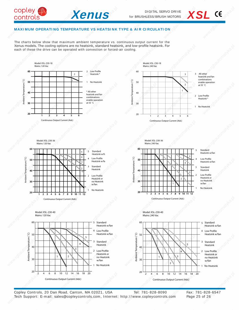
The charts below show that maximum ambient temperature vs. continuous output current for the Xenus models. The cooling options are no heatsink, standard heatsink, and low-profile heatsink. For each of these the drive can be operated with convection or forced-air cooling.
MAXIMUM OPERATING TEMPERATURE VS HEATSINK TYPE & AIR CIRCULATION
ENCODER RESOLVER DESCRIPTION
XSL-230-18 XSL-230-18-R Xenus Servo Drive 6/18 Adc
XSL-230-36 XSL-230-36-R Xenus Servo Drive 12/36 Adc
XSL-230-40 XSL-230-40-R Xenus Servo Drive 20/40 Adc
QTY REF DESCRIPTION MANUFACTURERS PART NUMBER
XSL-CK
Connector KitwithSolder Cup ConnectorsforJ7 & J8
1 J1 Plug, 4 position, 7.5 mm, female Wago: 721-204/026-045 (Note 1)
1 J2 Plug, 4 position, 5.0 mm, female Wago: 721-104/026-047 (Note 1)
1 J3 Plug, 5 position, 5.0 mm, male Wago: 721-605/000-044 (Note 1)
1 J4 Plug, 3 position, 5.0 mm, female Wago: 721-103/026-047 (Note 1)
4 J1~4 Tool, wire insertion & extraction (for J1~4) Wago: 231-131
1J7
Connector, 26 position, solder-cup 3M: 10126-3000VE
1 Back shell, for 26 position connector 3M: 10326-52F0-008
1J8
Connector, 20 position, solder cup 3M: 10120-3000VE
1 Back shell, for 20 position connector 3M: 10320-52F0-008
XSL-CA
Connector KitwithMolded Cables forJ7 & J8
1 J1 Plug, 4 position, 7.5 mm, female Wago: 721-204/026-045 (Note 1)
1 J2 Plug, 4 position, 5.0 mm, female Wago: 721-104/026-047 (Note 1)
1 J3 Plug, 5 position, 5.0 mm, male Wago: 721-605/000-044 (Note 1)
1 J4 Plug, 3 position, 5.0 mm, female Wago: 721-103/026-047 (Note 1)
4 J1~4 Tool, wire insertion & extraction (for J1~4) Wago: 231-131
1 J7 Cable assembly, control, 10 ft (3 m) Molex: 52316-2611, plug assy, Molex 52370-2610 boot cover
1 J8 Cable assembly, feedback, 10 ft (3 m) Molex: 52316-2011, plug assy, Molex 52370-2010 boot cover
XSL-CC-10 J7 Cable + molded connector, control, 10 ft (3 m) Molex: 52316-2611, plug assy, Molex 52370-2610 boot cover
XSL-FC-10 J8 Cable + molded connector, feedback, 10 ft (3 m) Molex: 52316-2011, plug assy, Molex 52370-2010 boot cover
CME 2J5
CME 2 Drive Configuration Software (CD-ROM)
SER-CK RS-232 Cable Kit
Note 1: For RoHS compliance, append “/RN01-0000” to the part numbers listed above
Connectors & Software for CANopen Operation
XSL-NK
1
J6
D-Sub 9F to RJ-45 Adapter XSL-CV
1 CAN bus RJ-45 terminator XSL-NT
1 CAN bus network cable, 10 ft (3 m) PC Connection Item#: 222440, Ethernet Patch cable, 10 ft
XSL-CV D-Sub 9F to RJ-45 Adapter
XSL-NC-10 CAN bus Network Cable, 10 ft (3 m) PC Connection Item#: 222440, Ethernet Patch cable, 10 ft
XSL-NC-01 CAN bus Network Cable, 1 ft (0.3 m) PC Connection Item#: 413209, Ethernet Patch cable, 1 ft.
XSL-NT CAN bus Network Terminator
CMO 1 CD with CMO Software
CML 1 CD with CML Software (Note: license fee required)
Heatsink Kits for Field Installation (Optional)
XSL-HL Heatsink Kit Low-Profile
1 Heatsink, low-profile
1 Heatsink thermal material
4 Heatsink hardware
XSL-HS Heatsink Kit Standard
1 Heatsink, standard
1 Heatsink thermal material
4 Heatsink hardware
Regeneration Resistors (Optional)
XTL-RA-03 Regeneration resistor assembly (for XSL-230-18)
XTL-RA-04 Regeneration resistor assembly (for XSL-230-36 & XSL-230-40 models)
Edge Filter (Optional)
XSL-FA-01 Edge filter
XSL-FK Edge filter connector kit
Copley Controls, 20 Dan Road, Canton, MA 02021, USA Tel: 781-828-8090 Fax: 781-828-6547 Tech Support: E-mail: [email protected], Internet: http://www.copleycontrols.com Page 26 of 26
DIGITAL SERVO DRIVE
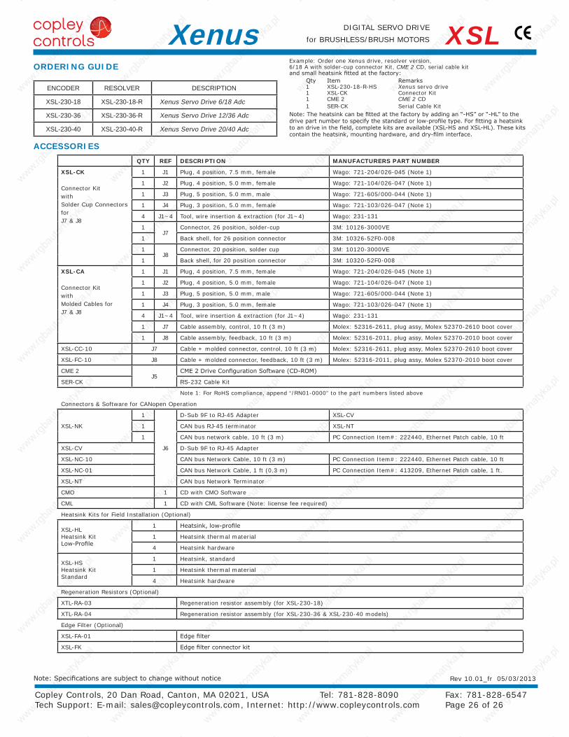
for BRUSHLESS/BRUSH MOTORSXenus XSLORDERING GUIDE
Example: Order one Xenus drive, resolver version, 6/18 A with solder-cup connector Kit, CME 2 CD, serial cable kit and small heatsink fitted at the factory:
Qty Item Remarks 1 XSL-230-18-R-HS Xenus servo drive 1 XSL-CK Connector Kit 1 CME 2 CME 2 CD 1 SER-CK Serial Cable Kit
Note: The heatsink can be fitted at the factory by adding an “-HS” or “-HL” to the drive part number to specify the standard or low-profile type. For fitting a heatsink to an drive in the field, complete kits are available (XSL-HS and XSL-HL). These kits contain the heatsink, mounting hardware, and dry-film interface.
ACCESSORIES
Rev 10.01_fr 05/03/2013Note: Specifications are subject to change without notice