Embed Size (px)
Citation preview
STRONGINTERNATIONALa division of Ballantyne of Omaha, Inc.4350 McKinley StreetOmaha, Nebraska 68112 USATel 402/453-4444 • Fax 402/453-7238www.strongint.com
XENON GLADIATOR IVFollow Spotlight
Type 47070
Rev. April 2003

PREFACE
STRONG INTERNATIONAL’S XENON GLADIATOR IV Model 47070 is a direct currentfollow spotlight system complete with a lamphouse, xenon power supply, optical system, color boomerang, andbase stand assembly. The spotlight assembly consists of the arc lamp, variable focus lens system, color boomer-ang, and base. The separate xenon power supply completes the installation.
ONLY THE SPECIAL XENON POWER SUPPLIES manufactured by Strong Internationalcan be used with the Gladiator IV. For installation and operation of the power supply, see the instruction manualfurnished separately.
THE XENON LAMPHOUSE utilizes a 4000 watt xenon bulb designed for horizontal opera-tion, and a deep ellipse metal reflector, as a light source. The reflector is designed to operate in a fixed position,and is dichroic (“cold”) coated to reduce heat in the projected light. A lens blower and heat filter, mounted in thespotlight optical system, further reduce heat at the projection lens and color media.
ONLY XENON BULBS designed for horizontal operation should be used in this follow spot.The Gladiator IV system includes a Type HS (Horizontal Short) 4500 watt bulb, and replacement bulbs (4000-4500 watt, not exceeding 4500 watts) must be certified as 100% interchangeable with this bulb. All requiredbulb cabling and contact clamps are provided in the xenon lamphouse, and bulb adapters are not required.
ADJUSTMENT CONTROL for the xenon bulb is located at the rear of the lamphouse behindthe access cover. The adjustments control the horizontal, vertical and focal movement of the bulb.
INSTRUMENTATION of the lamphouse includes a digital running time meter with DC volt-age and amperage display. A “wattage” readout on the digital display is an approximate figure and should notdictate the bulb’s output setting. The running time meter records the elapsed hours of the bulb (resettable), andthe total hours that the spotlight system has been in operation. A rocker switch controls lamp ON/OFF.
THE LAMPHOUSE COOLING BLOWERS are internally wired and operate on AC voltagederived from the xenon power supply. These blowers are required to maintain a safe operating temperature atthe bulb seals. An additional blower cools the optical system and color boomerang. The blowers operatecontinuously until the xenon power supply is de-energized.
THE LAMPHOUSE is supplied with a 13 foot cable containing the DC leads, the AC controlwires, and the ground wire. The cable terminates in a multiple-pin, quick-disconnect plug keyed to mate withthe receptacle on the power supply.
WHEN TRANSPORTING THE SPOTLIGHT, it is necessary to remove the xenon bulb andplace it in its original shipping container to prevent breakage. See the SAFETY PROCEDURES sectionfollowing, and permit only authorized personnel to handle the xenon bulb.
IF AT ANY TIME you have a suggestion, or desire aid in securing anticipated results, writedirectly to STRONG INTERNATIONAL, 4350 McKinley Street, Omaha, Nebraska 68112 USA, or online atwww.strongint.com.
XG4/001
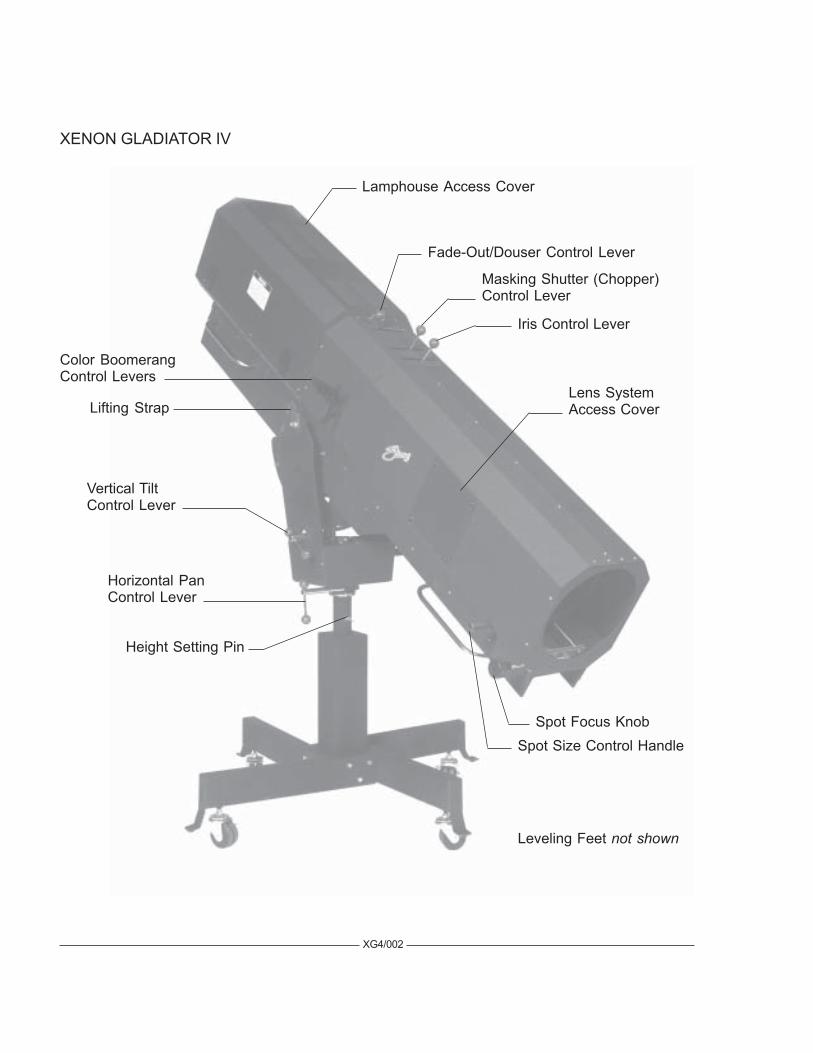
XG4/002
Lamphouse Access Cover
Fade-Out/Douser Control Lever
Masking Shutter (Chopper)Control Lever
Iris Control Lever
Horizontal PanControl Lever
Vertical TiltControl Lever
Height Setting Pin
Lifting Strap
Spot Size Control Handle
Color BoomerangControl Levers
Spot Focus Knob
Leveling Feet not shown
Lens SystemAccess Cover
XENON GLADIATOR IV

INSTALLATION AND SETTING UP SPOTLIGHT
THE XENON GLADIATOR IV is shipped in sections which must be assembled. Liftingstraps on the yoke assembly permit completely assembling the spotlight on the floor and later hoisting it to anelevated position.
ASSEMBLE THE FOUR BASE LEGS to the lower square section of the base column usingthe 3/8-16 x 2-3/4 inch hex head cap screws and lockwashers provided. Insert a leveling foot and locknut ineach of the four leg brackets and level the base before continuing the installation.
WHEN INSTALLED in a permanent location, the casters and leveling feet must be removed,and the clearance holes in the base leg brackets used for hardware (user supplied) to bolt the base to the floor orplatform. If it is desired to have the unit portable, when operating, the leveling feet must be adjusted down untilthe weight of the spotlight has been shifted from the casters to the leveling feet.
THE INNER TUBE of the support yoke has three holes to permit adjusting the height of thespotlight. The three holes are on four-inch centers and will allow an optical height of approximately 53 inches,57 inches, and 61 inches above floor level to the optical center of the lamphouse and lens system. Insert theheight location pin through the hole in the outer tube and one of the holes in the inner tube. The leveling feetmay be adjusted through an additional two-inch range.
THE HORIZONTAL SWING and vertical tilt locking knobs are on the right hand (operating)side of the yoke assembly. Level the yoke and tighten both of these locking devices securely before attemptingto place the lamphouse and lens system on the support yoke.
PLACE THE LAMPHOUSE and lens system on the yoke assembly, with the spot size controlhandle to the right hand (operating) side, the same as the locking controls on the yoke. Line up the four tapped(5/16-18) mounting holes in the bottom of the base rail mounting bracket with the four mating holes in thesupport yoke and secure using the four 5/16-18 wing screws. Note the mounting holes are slotted to allow fineadjustment for balancing the spotlight.
ATTACH THE LAMPHOUSE CABLE CONNECTOR to the mating receptacle on the powersupply. The lamphouse and power supply connectors are keyed for correct pin alignment; make certain pins areseated before tightening the locking ring. DO NOT energize the xenon power supply before the xenon bulb iscorrectly installed into the lamphouse.
XG4/003
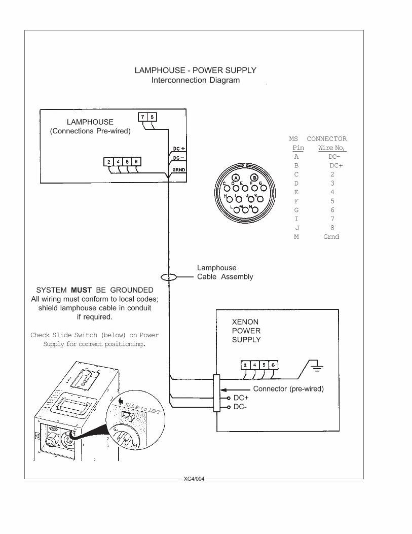
LAMPHOUSE - POWER SUPPLYInterconnection Diagram
LAMPHOUSE(Connections Pre-wired)
MS CONNECTORPin Wire No,A DC-B DC+C 2D 3E 4F 5G 6 I 7 J 8M Grnd
LamphouseCable Assembly
XENONPOWERSUPPLY
Connector (pre-wired)DC+DC-
XG4/004
SYSTEM MUST BE GROUNDEDAll wiring must conform to local codes;
shield lamphouse cable in conduitif required.
Check Slide Switch (below) on PowerSupply for correct positioning.
Slide to LEFT
SAFETY PROCEDURES
READ CAREFULLY BEFORE INSTALLING XENON BULB
THE XENON BULB is highly pressurized. When ignited, the normal operating temperatureof the bulb increases the pressure to a level at which the bulb may explode if not handled in strict accordance tothe manufacturer’s operating instructions.
THE BULB is stable at room temperature, but may still explode if dropped or otherwise mis-handled. Breakage resulting from transport and handling is not covered by the bulb manufacturer’s warranty,and it is strongly recommended to dismount the xenon bulb when transporting the spotlight.
REFER bulb replacement and service to QUALIFIED PERSONNEL with adequate protec-tive clothing (face shield, clean cotton gloves, welder’s jacket). For routine lamphouse service, observe thefollowing rules:
1. Allow the bulb to cool to room temperature before opening the lamphouse. Put on protective clothingdescribed above.
2. De-energize the xenon power supply at the AC source before opening the lamphouse compartment.
3. When possible, encase the bulb in its protective cover when cleaning or servicing the lamphouse inte-rior. The bulb, when outside the lamphouse, must be encased in the cover.
4. Clean the bulb after it has cooled to room temperature. Do not touch the quartz envelope of the bulb;fingerprints will burn in and create hot spots which may shorten bulb life. If fingermarks are made,they should be carefully removed with methyl alcohol and cotton prior to bulb operation.
5. Never view an ignited bulb directly. BLINDNESS OR PERMANENT EYE DAMAGE MAY BEINCURRED.
6. Use only xenon bulbs designated as OZONE FREE. When possible, vent the lamphouse exhaust tooutside atmosphere.
7. Maintain the lamphouse blowers in good operating condition. Keep the blower inlets and grilles cleanfor unrestricted air flow.
8. To insure maximum bulb life, operate the lamphouse blowers for at least ten minutes after extinguish-ing the bulb.
9. If returning a bulb for warranty adjustment, pack it in its original shipping container. Complete andreturn all required warranty information.
XG4/005
10. Dispose of expired bulbs that are beyond warranty in the following manner: Wrap the bulb tightly inseveral layers of canvas or heavy cloth. Place it on a hard surface and shatter the envelope with a sharphammer blow. DO NOT place an unshattered bulb in an ordinary refuse container.
11. DO NOT PERMIT UNAUTHORIZED PERSONNEL TO PERFORM OR ATTEMPT ANY PHASEOF XENON BULB HANDLING OR SERVICE.
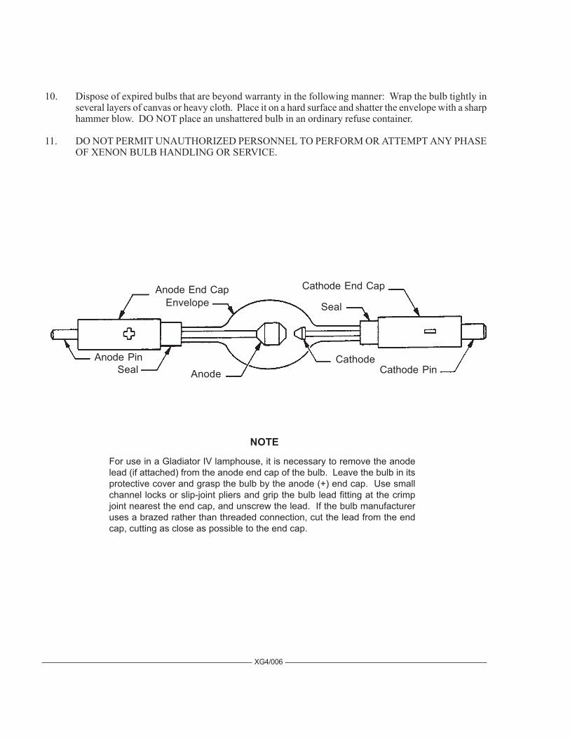
Cathode PinCathode
AnodeAnode Pin
Cathode End Cap
Seal
SealEnvelopeAnode End Cap
XG4/006
For use in a Gladiator IV lamphouse, it is necessary to remove the anodelead (if attached) from the anode end cap of the bulb. Leave the bulb in itsprotective cover and grasp the bulb by the anode (+) end cap. Use smallchannel locks or slip-joint pliers and grip the bulb lead fitting at the crimpjoint nearest the end cap, and unscrew the lead. If the bulb manufactureruses a brazed rather than threaded connection, cut the lead from the endcap, cutting as close as possible to the end cap.
NOTE
BULB INSTALLATION
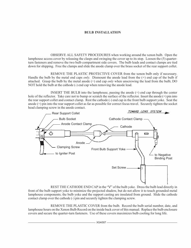
OBSERVE ALL SAFETY PROCEDURES when working around the xenon bulb. Open thelamphouse access cover by releasing the clasps and swinging the cover up to its stop. Loosen the (5) quarter-turn fasteners and remove the two bulb compartment side covers. The bulb leads and contact clamps are tieddown for shipping. Free the clamps and slide the anode clamp over the brass socket of the rear support collet.
REMOVE THE PLASTIC PROTECTIVE COVER from the xenon bulb only if necessary.Handle the bulb by the metal end caps only. Dismount the anode lead from the (+) end cap of the bulb ifattached. Grasp the bulb by the metal anode (+) end cap only when unscrewing the lead from the bulb; DONOT hold the bulb at the cathode (-) end cap when removing the anode lead.
INSERT THE BULB into the lamphouse, passing the anode (+) end cap through the centerhole of the reflector. Take care not to bump or scratch the surface of the reflector. Insert the anode (+) pin intothe rear support collet and contact clamp. Rest the cathode (-) end cap in the front bulb support yoke. Seat theanode (+) pin into the rear support collet as far as possible for correct focus travel. Securely tighten the sockethead clamping screw in the anode contact.
REST THE CATHODE END CAP in the “V” of the bulb yoke. Dress the bulb lead directly infront of the bulb support yoke to minimize the projected shadow, but do not allow it to touch grounded metallamphouse components; the bulb yoke and the support casting are insulated from ground. Slide the cathodecontact clamp over the cathode (-) pin and securely tighten the clamping screw.
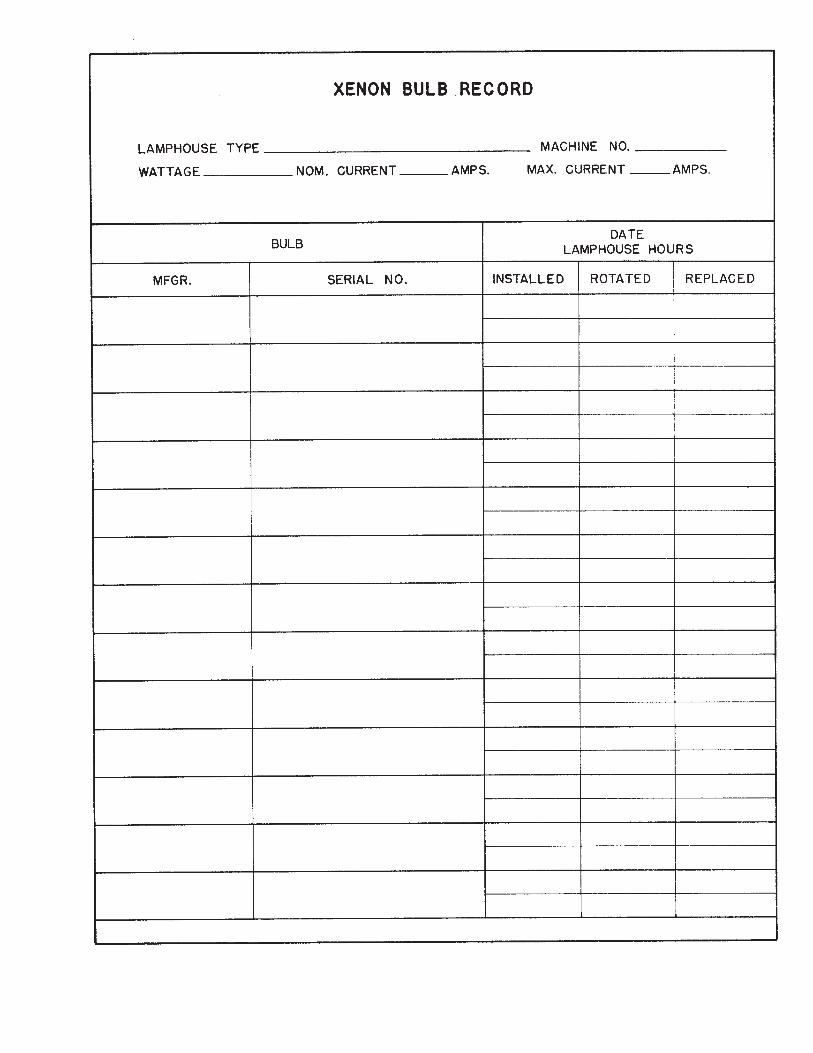
REMOVE THE PLASTIC COVER from the bulb. Record the bulb serial number, date, andlamphouse hours on the Xenon Bulb Record on the inside back cover of this manual. Replace the bulb enclosurecovers and secure the quarter-turn fasteners. Use of these covers maximizes bulb cooling for long life.
XG4/007
Rear Support Collet
Bulb SocketAnode Contact Clamp
AnodeClamping Screw
to Igniter Post
Cathode
Front Bulb Support Yoke
Set Screw
Cathode Contact Clamp
to NegativeBinding Post
ESTABLISH A ROUTINE of periodically checking all electrical connections for tightness.Loose contacts, particularly in the DC circuit, will cause overheating and damage the xenon bulb and othercomponents. Normal xenon bulb warranties allow no credit for bulb damage caused by overheating.
REFER TO THE BULB MANUFACTURER’S INSTRUCTIONS regarding bulb rotation.Most bulb manufacturers recommend rotating the bulb 180° at 50% of warranty hours. After rotating the bulb,operate at maximum allowable current for several hours, and then return to the nominal operating current.
IN THE EVENT of a bulb warranty claim, the bulb must be packaged in its original shippingcontainer, and returned with all required warranty forms completed. Contact the dealer through whom the bulbwas originally purchased for correct procedures and Return Authorizations.
IT IS A COMMON PRACTICE to replace the bulb at the expiration of its warranty period. Ifa xenon bulb explodes in operation, the reflector and other lamphouse components are frequently damaged. Thexenon bulb manufacturer will extend no credit for a replacement reflector if the defective bulb is beyond war-ranty. Explosion-damaged reflectors are to be returned to the bulb supplier, NOT Strong International, unlessthe bulb was supplied by Strong.
XG4/008
ARC STABILIZATION MAGNET
THE XENON BULB used in the Gladiator IV lamphouse requires an arc stabilization magnet.This magnet is located below and behind the reflector. The magnet is preset at the factory and should notrequire adjustment. Should it become necessary to adjust the magnet, the following procedure must befollowed. Observe all bulb safety procedures when working in the lamphouse compartment.
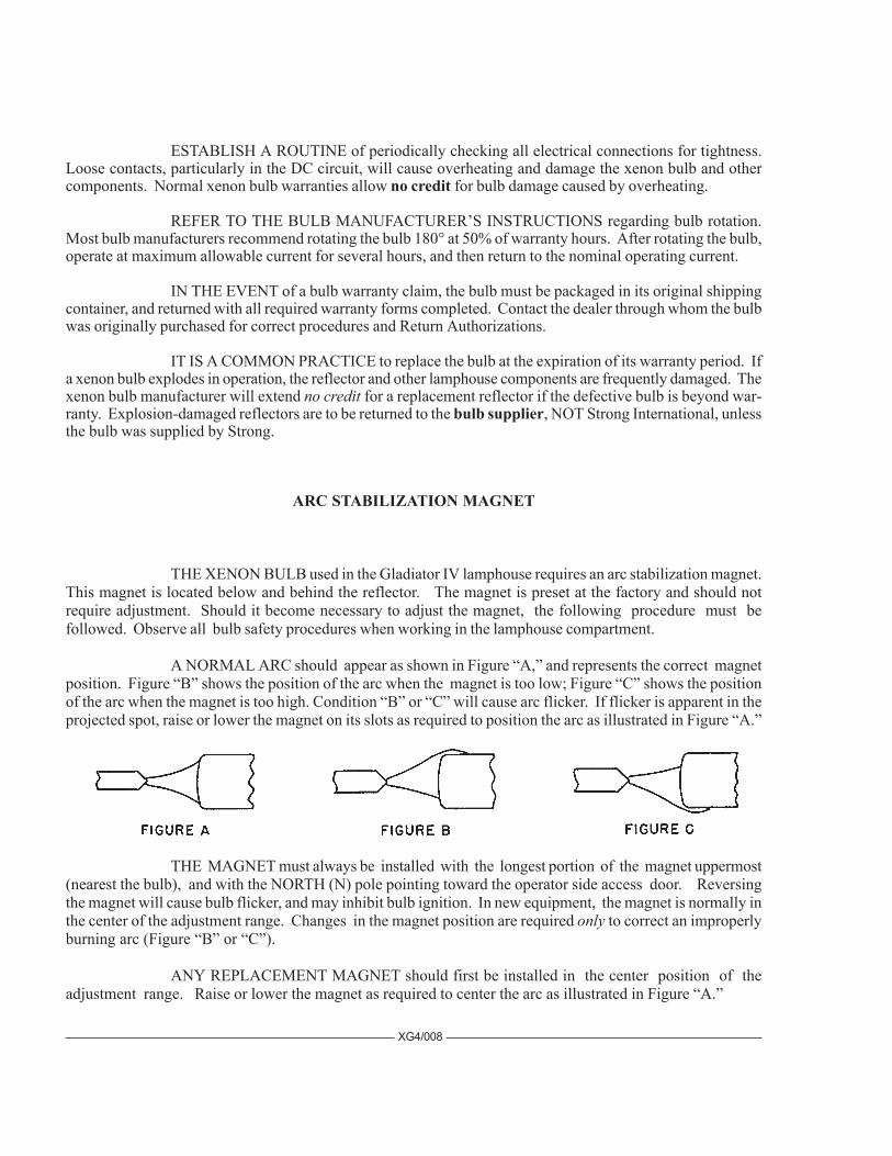
A NORMAL ARC should appear as shown in Figure “A,” and represents the correct magnetposition. Figure “B” shows the position of the arc when the magnet is too low; Figure “C” shows the positionof the arc when the magnet is too high. Condition “B” or “C” will cause arc flicker. If flicker is apparent in theprojected spot, raise or lower the magnet on its slots as required to position the arc as illustrated in Figure “A.”
THE MAGNET must always be installed with the longest portion of the magnet uppermost(nearest the bulb), and with the NORTH (N) pole pointing toward the operator side access door. Reversingthe magnet will cause bulb flicker, and may inhibit bulb ignition. In new equipment, the magnet is normally inthe center of the adjustment range. Changes in the magnet position are required only to correct an improperlyburning arc (Figure “B” or “C”).
ANY REPLACEMENT MAGNET should first be installed in the center position of theadjustment range. Raise or lower the magnet as required to center the arc as illustrated in Figure “A.”
OPERATION
OPEN THE BOOMERANG ACCESS COVER and verify that the round glass heat filter andring assembly is installed into the bracket mounted to the fadeout and douser support housing. NOTE: Thecoated side of the filter, with the XX or other marking, must be facing the reflector.
REMOVE THE PLASTIC COVER from the xenon bulb. DO NOT ignite the lamp with thecover on the bulb. Store the cover for future re-use. Replace and secure the bulb enclosure covers.
CLOSE THE LAMPHOUSE COVER and secure using both latches. Turn on the main lineswitch and/or circuit breaker to energize the xenon power supply. The spotlight blowers will start and operatecontinuously until the xenon power supply is de-energized.
PLACE THE LAMP SWITCH in the “ON” position and the lamp will ignite. Check thereading on the lamphouse ammeter. Nominal current for the 4500 watt xenon bulb is 135 amperes. DO NOT,AT ANY TIME, exceed 150 amperes; the “wattage” readout on the digital display is an approximate figureand should not dictate the output setting. Output current is adjusted at the xenon power supply; see powersupply manual for instructions. Operation of a new bulb is normally started at the lower end of its range (125 A.),and current is gradually increased as the bulb ages to maintain light output. During the ignition cycle, the displaywill also briefly indicate the high “no load” (open circuit) DC voltage applied to the xenon bulb for ignition.
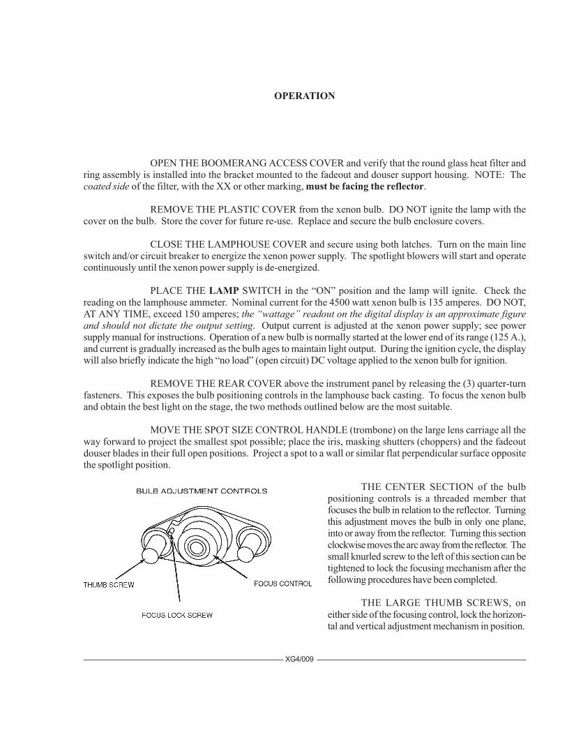
REMOVE THE REAR COVER above the instrument panel by releasing the (3) quarter-turnfasteners. This exposes the bulb positioning controls in the lamphouse back casting. To focus the xenon bulband obtain the best light on the stage, the two methods outlined below are the most suitable.
MOVE THE SPOT SIZE CONTROL HANDLE (trombone) on the large lens carriage all theway forward to project the smallest spot possible; place the iris, masking shutters (choppers) and the fadeoutdouser blades in their full open positions. Project a spot to a wall or similar flat perpendicular surface oppositethe spotlight position.
XG4/009
THE CENTER SECTION of the bulbpositioning controls is a threaded member thatfocuses the bulb in relation to the reflector. Turningthis adjustment moves the bulb in only one plane,into or away from the reflector. Turning this sectionclockwise moves the arc away from the reflector. Thesmall knurled screw to the left of this section can betightened to lock the focusing mechanism after thefollowing procedures have been completed.
THE LARGE THUMB SCREWS, oneither side of the focusing control, lock the horizon-tal and vertical adjustment mechanism in position.
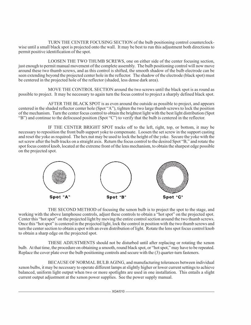
TURN THE CENTER FOCUSING SECTION of the bulb positioning control counterclock-wise until a small black spot is projected onto the wall. It may be best to run this adjustment both directions topermit positive identification of the spot.
LOOSEN THE TWO THUMB SCREWS, one on either side of the center focusing section,just enough to permit manual movement of the complete assembly. The bulb positioning control will now movearound these two thumb screws, and as this control is shifted, the smooth shadow of the bulb electrode can beseen extending beyond the projected center hole in the reflector. The shadow of the electrode (black spot) mustbe centered in the projected hole of the reflector (shaded, less dense dark area).
MOVE THE CONTROL SECTION around the two screws until the black spot is as round aspossible to project. It may be necessary to again turn the focus control to project a sharply defined black spot.
AFTER THE BLACK SPOT is as even around the outside as possible to project, and appearscentered in the shaded reflector center hole (Spot “A”), tighten the two large thumb screws to lock the positionof the mechanism. Turn the center focus control to obtain the brightest light with the best light distribution (Spot“B”) and continue to the defocused position (Spot “C”) to verify that the bulb is centered in the reflector.
IF THE CENTER BRIGHT SPOT tracks off to the left, right, top, or bottom, it may benecessary to reposition the front bulb support yoke to compensate. Loosen the set screw in the support castingand reset the yoke as required. The hex nut may be used to lock the height of the yoke. Secure the yoke with theset screw after the bulb tracks on a straight axis. Return the focus control to the desired Spot “B,” and rotate thespot focus control knob, located at the extreme front of the lens mechanism, to obtain the sharpest edge possibleon the projected spot.
XG4/010
THE SECOND METHOD of focusing the xenon bulb is to project the spot to the stage, andworking with the above lamphouse controls, adjust these controls to obtain a “hot spot” on the projected spot.Center this “hot spot” on the projected light by moving the entire control section around the two thumb screws.Once this “hot spot” is centered in the projected light, lock the control in position with the two thumb screws andturn the center section to obtain a spot with an even distribution of light. Rotate the lens spot focus control knobto obtain a sharp edge on the projected spot.
THESE ADJUSTMENTS should not be disturbed until after replacing or rotating the xenonbulb. At that time, the procedure on obtaining a smooth, round black spot, or “hot spot,” may have to be repeated.Replace the cover plate over the bulb positioning controls and secure with the (3) quarter-turn fasteners.
BECAUSE OF NORMAL BULB AGING, and manufacturing tolerances between individualxenon bulbs, it may be necessary to operate different lamps at slightly higher or lower current settings to achievebalanced, uniform light output when two or more spotlights are used in one installation. This entails a slightcurrent output adjustment at the xenon power supplies. See the power supply manual.
XG4/011
TO EXTINGUISH the arc, place the LAMP switch on the instrument panel to “OFF.” Thelamphouse blowers will continue to operate until the xenon power supply is de-energized. Allow the blowers tooperate for ten minutes before turning off the power supply; a forced-air bulb cooling cycle at shutdown isrequired by all bulb manufacturers to comply with their warranty terms.
BEFORE OPENING the lamphouse enclosure for servicing, allow the blowers to operate fortwenty minutes, or until the bulb has cooled to room temperature.
HANDLING THE SPOTLIGHT
GENERALLY THE BEST POSITION for the operator to stand is near the center of the spot-light on the right side. The angle of tilt, the size of the porthole, and the layout of the spotlight position maydictate another location.
EACH OPERATOR will, after a few minutes of operation, generally develop his own systemand position for most convenient operation.
THE HORIZONTAL SWING and vertical tilt are individually adjustable to give the desireddegree of friction to suit the operator. The locking clamps are located on the right side of the yoke assembly.
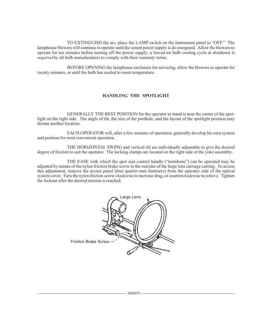
THE EASE with which the spot size control handle (“trombone”) can be operated may beadjusted by means of the nylon friction brake screw in the outrider of the large lens carriage casting. To accessthis adjustment, remove the access panel (four quarter-turn fasteners) from the operator side of the opticalsystem cover. Turn the nylon friction screw clockwise to increase drag, or counterclockwise to relieve. Tightenthe locknut after the desired tension is reached.
Large Lens
Friction Brake Screw
OPERATION OF OPTICAL SYSTEM
THE IRIS CONTROL is the front lever which projects through the top of the optical systemhousing. When this lever is to the left (as viewed from the rear of the unit), the largest aperture is provided.Smaller apertures are obtained as the lever is moved to the right.
THE SPOT SIZE CONTROL HANDLE is located on the right hand side of the optical systemjust above the base rail. A variation of spot sizes from full flood to small spot can be obtained by moving thespot size control handle from one extreme to the other. Beam intensity is increased by this optical system whenreducing from flood to spot, and maximum intensity is reached when the spot size control handle is in theextreme forward position. Rotating the handle allows a slight degree of spot focus.
THE MAXIMUM FLOOD SPOT is obtained with the iris control lever to the left (away fromoperating side) for the largest aperture and with the spot size control handle moved as far to the rear as possible.
SMALLER SIZED SPOTS are projected as the spot size control handle is moved forward.Most of the spot sizes needed will be produced with the iris in its maximum open position.
FOR A “HEAD SPOT,” or any spot smaller than can be obtained with the spot size controlhandle in its extreme forward position, shift the iris control lever to the right (toward operating side) for asmaller aperture. The iris control lever should always be returned to its extreme left position before the spot sizecontrol handle is again moved to obtain larger spots.
THE MASKING SHUTTER (chopper) lever is the middle lever projecting through the top ofthe optical system housing. The masking shutter blades are operated by this lever to shape the projected spot toa rectangle, strip spot, or dousing.
THE DISENGAGED POSITION of the masking shutter lever is to the extreme right (towardoperating side) and varying degrees of masking to complete cutoff are obtained by moving the lever to the left(away from operating side). If dousing the spot for a prolonged period with the bulb operating, it is highlyrecommended to use the Fadeout dousers (below) to prevent heat damage to the masking shutter blades.
THE ANGLE of the masking shutter blades can be adjusted to compensate for the horizontalprojection angle. Remove the color arm cover plate and dismount the boomerang. Loosen the (4) screwsholding each of the masking shutter blades enough to allow adjustments. Ignite the bulb and adjust the angle ofthe bottom blade by tapping with a screwdriver so its projected edge lies parallel to the footlights. Tighten thescrew. Operate the masking shutter lever to close the blades. Adjust the upper blade to close in line with thebottom blade and tighten the screw.
THE FADEOUT MECHANISM AND DOUSER CONTROL is the rear lever projectingthrough the top of the optical system cover. This lever controls the intensity of light from complete fadeoutwhen the lever is to the left, to full intensity when the lever is to the right.
THE SPOT FOCUSING CONTROL KNOB is located on the operating side of the opticalsystem at the forward end above the base rail. This control is used to adjust the optical system for the length ofthrow. When making an adjustment, rotate the spot focusing control knob until the sharpest edge is obtained onthe projected spot.
XG4/012
OPERATION OF COLOR BOOMERANG
THE COLOR BOOMERANG is equipped with six color arms. A “starter” set of six 50mmdichroic color discs is included. Additional colors, including color temperature reduction filters, are avail-able from most theatrical supply dealers.
COLOR FILTERS are controlled by the rearmost (6) levers of the color boomerang; the frontmostlever is the color release control. To engage individual color filters, lower the desired filter selector lever. Arocker catch located in the color disc housing holds the filter in position.
TO RELEASE A COLOR, lower the filter release lever or engage another color, thus releasingthe previous color automatically.
TO REPLACE A COLOR FILTER, it is recommended to dismount the boomerang assemblyfrom the spotlight and place it on a convenient working surface. Loosen the (2) quarter-turn fasteners andremove the side cover plate. The entire boomerang assembly can then be easily removed by loosening the singlecaptive screw securing the boomerang bracket to the base rail, and lifting the bracket off the (2) locating pins.When re-installing the boomerang, position the holes in the boomerang base plate on these pins before againsecuring the captive screw.
NOTE: WHEN PLACING COLOR FILTERS in the boomerang, the less dense colors (pink,amber) should be placed in the holders toward the rear of the boomerang (toward arc), and those of greaterdensity (red, green) should be placed in the holders toward the front of the boomerang (away from the arc). Thismeasure will prolong the useful life of the filters.
XG4/013
XG4/014
DIGITAL DISPLAY
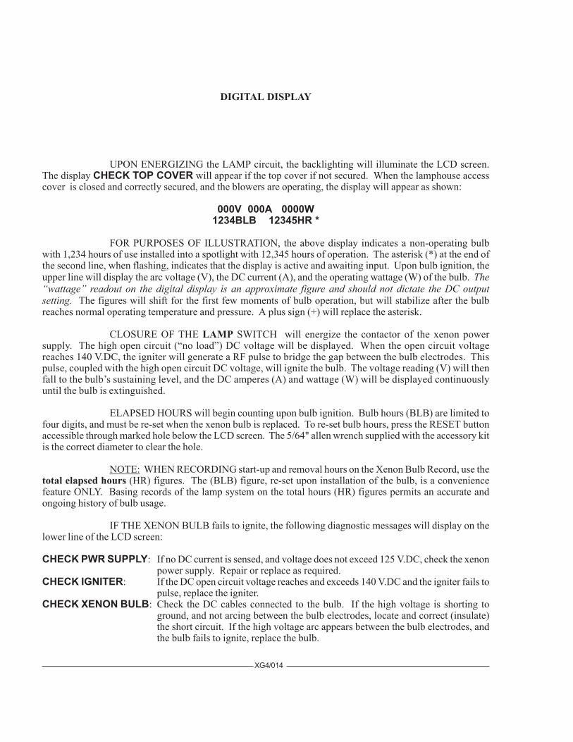
UPON ENERGIZING the LAMP circuit, the backlighting will illuminate the LCD screen.The display CHECK TOP COVER will appear if the top cover if not secured. When the lamphouse accesscover is closed and correctly secured, and the blowers are operating, the display will appear as shown:
000V 000A 0000W1234BLB 12345HR *
FOR PURPOSES OF ILLUSTRATION, the above display indicates a non-operating bulbwith 1,234 hours of use installed into a spotlight with 12,345 hours of operation. The asterisk (*) at the end ofthe second line, when flashing, indicates that the display is active and awaiting input. Upon bulb ignition, theupper line will display the arc voltage (V), the DC current (A), and the operating wattage (W) of the bulb. The“wattage” readout on the digital display is an approximate figure and should not dictate the DC outputsetting. The figures will shift for the first few moments of bulb operation, but will stabilize after the bulbreaches normal operating temperature and pressure. A plus sign (+) will replace the asterisk.
CLOSURE OF THE LAMP SWITCH will energize the contactor of the xenon powersupply. The high open circuit (“no load”) DC voltage will be displayed. When the open circuit voltagereaches 140 V.DC, the igniter will generate a RF pulse to bridge the gap between the bulb electrodes. Thispulse, coupled with the high open circuit DC voltage, will ignite the bulb. The voltage reading (V) will thenfall to the bulb’s sustaining level, and the DC amperes (A) and wattage (W) will be displayed continuouslyuntil the bulb is extinguished.
ELAPSED HOURS will begin counting upon bulb ignition. Bulb hours (BLB) are limited tofour digits, and must be re-set when the xenon bulb is replaced. To re-set bulb hours, press the RESET buttonaccessible through marked hole below the LCD screen. The 5/64" allen wrench supplied with the accessory kitis the correct diameter to clear the hole.
NOTE: WHEN RECORDING start-up and removal hours on the Xenon Bulb Record, use thetotal elapsed hours (HR) figures. The (BLB) figure, re-set upon installation of the bulb, is a conveniencefeature ONLY. Basing records of the lamp system on the total hours (HR) figures permits an accurate andongoing history of bulb usage.
IF THE XENON BULB fails to ignite, the following diagnostic messages will display on thelower line of the LCD screen:
CHECK PWR SUPPLY: If no DC current is sensed, and voltage does not exceed 125 V.DC, check the xenonpower supply. Repair or replace as required.
CHECK IGNITER: If the DC open circuit voltage reaches and exceeds 140 V.DC and the igniter fails topulse, replace the igniter.
CHECK XENON BULB: Check the DC cables connected to the bulb. If the high voltage is shorting toground, and not arcing between the bulb electrodes, locate and correct (insulate)the short circuit. If the high voltage arc appears between the bulb electrodes, andthe bulb fails to ignite, replace the bulb.

XG4/015
DIAGNOSTIC MESSAGES serve as prompts and suggestions but do not replace traditionaltroubleshooting procedures. If the top cover is closed and secured but transmits an error message, check thesubject cover interlock switch with an ohmmeter and replace if defective. Dirt or dust fouling an air vane switchwill cause a “blower” error message. A “power supply” or “igniter” error message might be caused by a looseor oxidized connection.
XG4/016
MAINTENANCE
THE XENON GLADIATOR IV SPOTLIGHT requires very little maintenance to keep it ingood working order.
THE REFLECTOR should be cleaned periodically with a soft, clean, lint-free cloth to removedust from the reflecting surface. If excessively soiled, the reflector may be cleaned with Windex® or an equiva-lent glass cleaner. DO NOT use abrasive cleaners of any kind. Clean the heat filter glass; replace with thecoated surface toward the lamphouse.
CHECK ALL ELECTRICAL CONNECTIONS for tightness on a regular basis. Loose con-nections, particularly in the DC circuit, may cause premature bulb failure and damage lamphouse components.
LUBRICATE the (3) squirrelcage blower motors with two or three drops of non-detergent oilonce every six months.
THE XENON BULB should be checked occasionally for the presence of dust or foreign mate-rials on the quartz envelope. If necessary, clean the envelope with alcohol, and wipe dry with a clean, lint-freecloth. Observe all safety procedures when working with the exposed bulb.
THE INSIDE OF THE LAMPHOUSE and the blower squirrelcages should be cleaned peri-odically, depending on the dust conditions at each installation. Keep the blower inlet and outlet grilles clean topermit free air flow.
THE LENS SYSTEM should be kept clean to prevent any light reduction in the projected spot.Tighten the horizontal swing and vertical tilt locking clamps. Remove the operator-side optical system accesspanel to clean the back surface of the large lens and access the small projection lens which is held in place witha large spring-type retainer ring at the front of its lens barrel.
CLEAN THE PROJECTION LENS and large lens with any cleaner approved for use oncoated projection lenses. Replace the projection lens with the end with the FL marking ring toward the iris;secure with the retainer ring.
BEFORE TRANSPORTING the spotlight, remove the xenon bulb from the lamphouse. Placethe bulb in its plastic cover and original shipping container.
CAUTION: DISCONNECT AC POWER BEFORE SERVICING
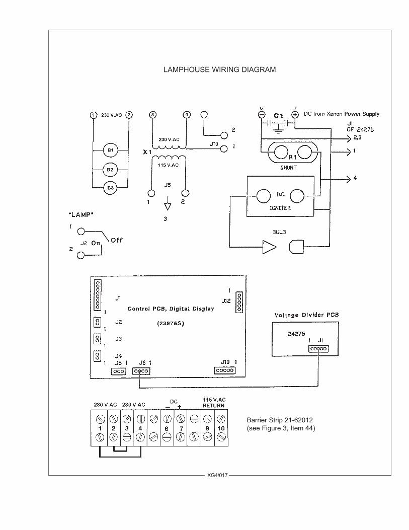
LAMPHOUSE WIRING DIAGRAM
XG4/017
Barrier Strip 21-62012(see Figure 3, Item 44)
XG4/018
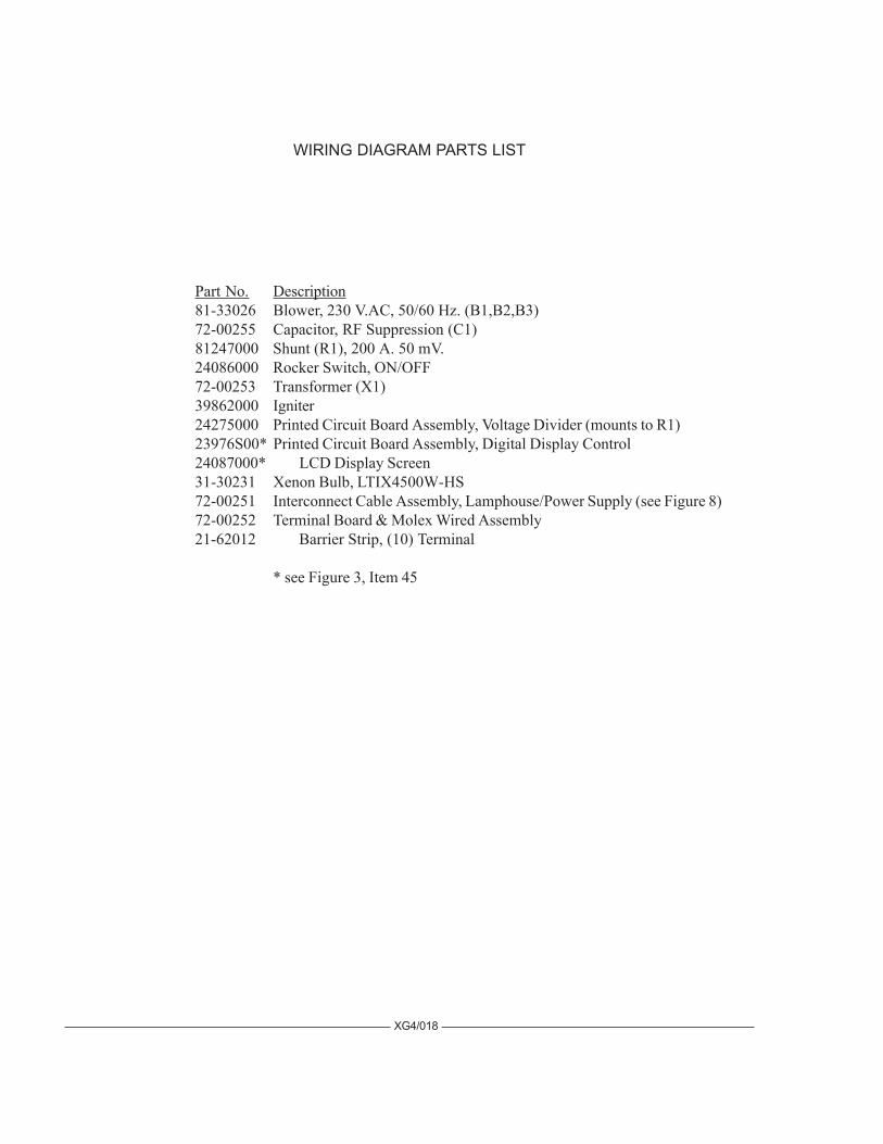
WIRING DIAGRAM PARTS LIST
Part No. Description81-33026 Blower, 230 V.AC, 50/60 Hz. (B1,B2,B3)72-00255 Capacitor, RF Suppression (C1)81247000 Shunt (R1), 200 A. 50 mV.24086000 Rocker Switch, ON/OFF72-00253 Transformer (X1)39862000 Igniter24275000 Printed Circuit Board Assembly, Voltage Divider (mounts to R1)23976S00* Printed Circuit Board Assembly, Digital Display Control24087000* LCD Display Screen31-30231 Xenon Bulb, LTIX4500W-HS72-00251 Interconnect Cable Assembly, Lamphouse/Power Supply (see Figure 8)72-00252 Terminal Board & Molex Wired Assembly21-62012 Barrier Strip, (10) Terminal
* see Figure 3, Item 45

XG4/019
2397
6S D
IGIT
AL D
ISPL
AYC
ON
TRO
L C
IRC
UIT
Page
1 0
f 3
XG4/020
2397
6S D
IGIT
AL D
ISPL
AYC
ON
TRO
L C
IRC
UIT
Page
2 0
f 3
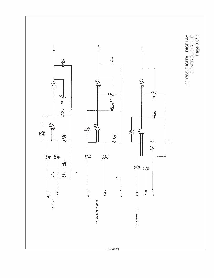
XG4/021
2397
6S D
IGIT
AL D
ISPL
AYC
ON
TRO
L C
IRC
UIT
Page
3 0
f 3
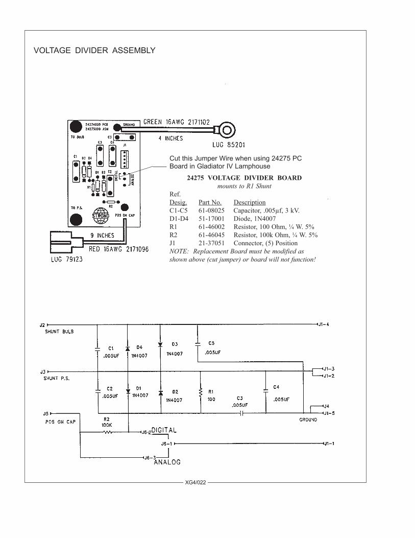
24275 VOLTAGE DIVIDER BOARDmounts to R1 Shunt
Ref.Desig. Part No. DescriptionC1-C5 61-08025 Capacitor, .005µf, 3 kV.D1-D4 51-17001 Diode, 1N4007R1 61-46002 Resistor, 100 Ohm, ¼ W. 5%R2 61-46045 Resistor, 100k Ohm, ¼ W. 5%J1 21-37051 Connector, (5) PositionNOTE: Replacement Board must be modified asshown above (cut jumper) or board will not function!
VOLTAGE DIVIDER ASSEMBLY
Cut this Jumper Wire when using 24275 PCBoard in Gladiator IV Lamphouse
XG4/022
XG4/023
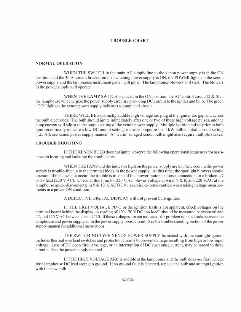
TROUBLE CHART
NORMAL OPERATION
WHEN THE SWITCH in the main AC supply line to the xenon power supply is in the ONposition, and the 30 A. circuit breaker on the switching power supply is ON, the POWER lights on the xenonpower supply and the lamphouse instrument panel will glow. The lamphouse blowers will start. The blowersin the power supply will operate.
WHEN THE LAMP SWITCH is placed in the ON position, the AC control circuit (2 & 6) inthe lamphouse will energize the power supply circuitry providing DC current to the igniter and bulb. The green“GO” light on the xenon power supply indicates a completed circuit.
THERE WILL BE a distinctly audible high voltage arc ping at the igniter arc gap and acrossthe bulb electrodes. The bulb should ignite immediately after one or two of these high voltage pulses, and thelamp current will adjust to the output setting of the xenon power supply. Multiple ignition pulses prior to bulbignition normally indicate a low DC output setting; increase output to the 4 kW bulb’s initial current setting(125 A.); see xenon power supply manual. A “warm” or aged xenon bulb might also require multiple strikes.
TROUBLE SHOOTING
IF THE XENON BULB does not ignite, observe the following operational sequences for assis-tance in locating and isolating the trouble area.
WHEN THE FANS and the indicator light on the power supply are on, the circuit in the powersupply is trouble-free up to the terminal block in the power supply. At this time, the spotlight blowers shouldoperate. If this does not occur, the trouble is in one of the blower motors, a loose connection, or a broken #7or #8 lead (220 V.AC). Check at this time for 220 V.AC blower voltage at wires 7 & 8, and 220 V.AC at thelamphouse quick-disconnect pins 9 & 10. CAUTION: exercise extreme caution when taking voltage measure-ments in a power ON condition.
A DEFECTIVE DIGITAL DISPLAY will not prevent bulb ignition.
IF THE HIGH VOLTAGE PING or the ignition flash is not apparent, check voltages on theterminal board behind the display. A reading of 120-170 V.DC “no load” should be measured between #6 and#7, and 115 V.AC between #9 and #10. If these voltages are not indicated, the problem is in the leads between thelamphouse and power supply, or in the power supply boost circuit. See the trouble shooting section of the powersupply manual for additional instructions.
THE SWITCHING-TYPE XENON POWER SUPPLY furnished with the spotlight systemincludes thermal overload switches and protection circuits to prevent damage resulting from high or low inputvoltage. Loss of DC open circuit voltage, or an interruption of DC sustaining current, may be traced to thesecircuits. See the power supply manual.
IF THE HIGH VOLTAGE ARC is audible at the lamphouse and the bulb does not flash, checkfor a lamphouse DC lead arcing to ground. If no ground fault is detected, replace the bulb and attempt ignitionwith the new bulb.

XG4/024
Bulb fails to ignite.
1. AC power not on to lamphouse. Turn switching power supply 30 A. circuit breaker ON. If 230 V.ACnot read at 1 & 2, or POWER indicator not glowing, see power supply manual.
2. Faulty “ON-OFF” switch. Check for voltage at terminal block positions 9 & 10; check for looseterminals or wiring. Replace if defective.
3. Low AC source voltage actuating “brownout” protection circuit in xenon power supply.
Bulb fails to ignite; ping audible, bulb flash visible.
1. Inadequate DC output from xenon power supply. Set power supply output to correct range required forbulb wattage (120-150 A. for 4000 watt). Do not exceed 150 A.
2. If bulb flash is visible but faint, check for defective printed circuit board in igniter. Replace if defective. 3. Faulty or expired xenon bulb. Replace as required.
Bulb fails to ignite; ping audible, no bulb flash.
1. Faulty xenon bulb. Check for cracked electrodes or darkened envelope. Replace if defective. 2. Ignition pulse shorting to ground. Inspect DC leads for burned insulation; dress leads away from
grounded metal components.
No high voltage ping audible; LAMP switch in “ON.”
1. Loss of AC control voltage. Check xenon power supply for tripped circuit breaker or open thermalswitch. See power supply manual.
2. Lamphouse top cover interlock switch open. Top cover must be closed and both latches secured. 3. Xenon power supply “GO” light not glowing. See power supply manual. 4. Little or no DC “No Load” voltage. Measure DC “No Load” voltage at 6 & 7. See power supply
manual. 5. Open fuse F1 (10 A.) on switching power supply primary PC board. SEE POWER SUPPLY MANUAL.
Allow (20) minutes for capacitor discharge before replacing. 6. Loose spark gap connections or terminals. Repair or replace igniter PC board as required.
IF THE HIGH VOLTAGE ARC is audible at the lamphouse, the flash of the bulb is apparent,but ignition of the bulb is not sustained, the problem area is in the power supply. See the trouble shootingsection of the power supply manual for additional instructions.
IF THE HIGH VOLTAGE ARC is not audible or the flash of the bulb visible, the problem is inthe igniter assembly.
EXCHANGE of components (i.e. igniters, printed circuit boards) between similar StrongXenon Gladiators to aid in diagnosis of a problem is encouraged. This will not lead to equipment damage, andwill not void equipment warranty.
XENON GLADIATOR IV TROUBLESHOOTING
EXERCISE ALL DUE CAUTION WHEN MEASURINGVOLTAGES IN A “POWER ON” CONDITION
XG4/025
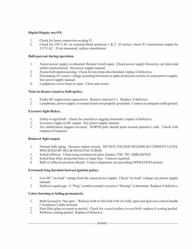
Digital Display not ON.
1. Check for loose connection on plug J5. 2. Check for 230 V.AC on terminal block positions 1 & 2. If correct, check X1 transformer output for
115 V.AC. If not measured, replace transformer.
Bulb goes out during operation.
1. Xenon power supply overheated; thermal switch open. Check power supply blower(s), air inlets andoutlets unobstructed. See power supply manual.
2. Xenon bulb depressurizing. Check for envelope discoloration; replace if defective. 3. Fluctuating AC source voltage actuating brownout or spike protection circuits in xenon power supply.
See power supply manual. 4. Lamphouse cover loose or open. Close and secure.
Noise in theatre sound as bulb ignites.
1. Faulty RF suppression capacitor(s). Remove and test C1. Replace if defective. 2. Lamphouse, power supply, or sound system not properly grounded. Connect to adequate earth ground.
Excessive light flicker..
1. Faulty or aged bulb. Check for cracked or sagging electrodes; replace if defective. 2. Excessive ripple in DC output. See power supply manual. 3. Arc stabilization magnet reversed. NORTH pole should point toward operator’s side. Check with
compass if required.
Reduced light output.
1. Normal bulb aging. Increase output current. DO NOT EXCEED MAXIMUM CURRENT LEVELSPECIFIED BY BULB MANUFACTURER.
2. Soiled reflector. Clean using commercial glass cleaner; USE NO ABRASIVES. 3. Soiled heat filter, projection lens, or large lens. Clean as required. 4. Bulb or reflector position altered. Correct alignment; see preceding OPERATION section.
Extremely long duration between ignition pulses.
1. Low DC “no load” voltage from the xenon power supply. Check “no load” voltage; see power supplymanual.
2. Defective spark gap. A “Ping” sound is normal; excessive “Hissing” is abnormal. Replace if defective.
Colors burning or fading prematurely.
1. Bulb focused to “hot spot.” Refocus bulb to flat field with iris fully open and spot size control handle(“trombone”) fully forward.
2. Heat filter glass reversed or peeled. Check for coated surface toward bulb; replace if coating peeled. 3. Reflector coating peeled. Replace if defective.

FIGURE 1
XG4/026
1
2 3
4
5
67
8
910
12
13
7
14
15
11
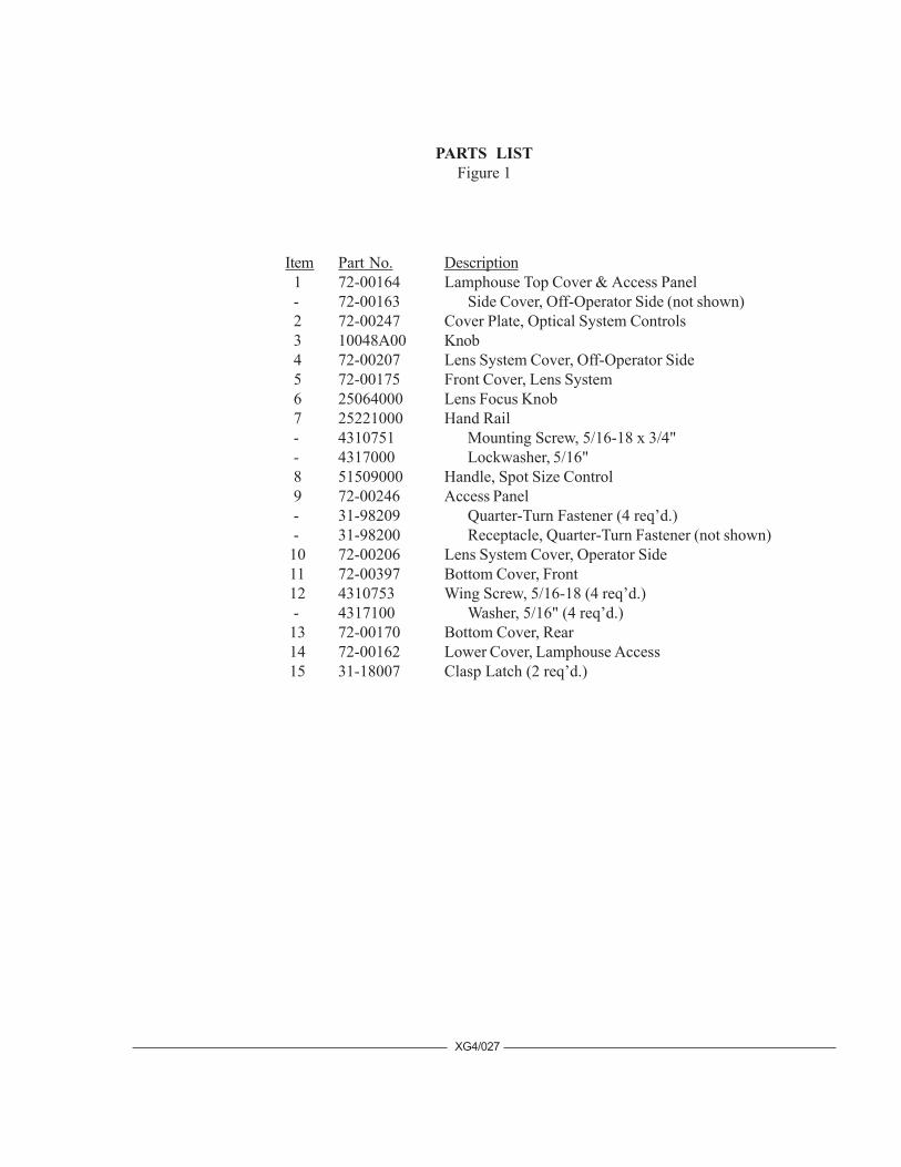
PARTS LISTFigure 1
Item Part No. Description 1 72-00164 Lamphouse Top Cover & Access Panel - 72-00163 Side Cover, Off-Operator Side (not shown) 2 72-00247 Cover Plate, Optical System Controls 3 10048A00 Knob 4 72-00207 Lens System Cover, Off-Operator Side 5 72-00175 Front Cover, Lens System 6 25064000 Lens Focus Knob 7 25221000 Hand Rail - 4310751 Mounting Screw, 5/16-18 x 3/4" - 4317000 Lockwasher, 5/16" 8 51509000 Handle, Spot Size Control 9 72-00246 Access Panel - 31-98209 Quarter-Turn Fastener (4 req’d.) - 31-98200 Receptacle, Quarter-Turn Fastener (not shown) 10 72-00206 Lens System Cover, Operator Side 11 72-00397 Bottom Cover, Front 12 4310753 Wing Screw, 5/16-18 (4 req’d.) - 4317100 Washer, 5/16" (4 req’d.) 13 72-00170 Bottom Cover, Rear 14 72-00162 Lower Cover, Lamphouse Access 15 31-18007 Clasp Latch (2 req’d.)
XG4/027

FIGURE 2
XG4/028
1
2
3
4
5
6
7
8
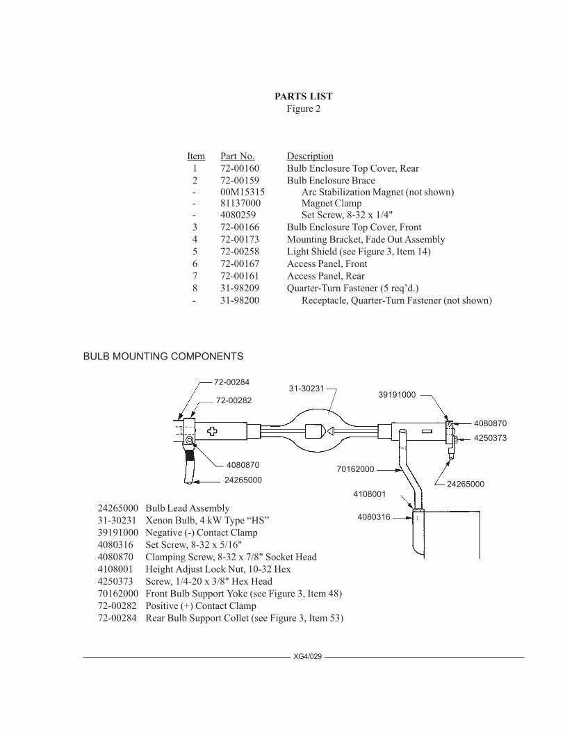
Item Part No. Description 1 72-00160 Bulb Enclosure Top Cover, Rear 2 72-00159 Bulb Enclosure Brace - 00M15315 Arc Stabilization Magnet (not shown) - 81137000 Magnet Clamp - 4080259 Set Screw, 8-32 x 1/4" 3 72-00166 Bulb Enclosure Top Cover, Front 4 72-00173 Mounting Bracket, Fade Out Assembly 5 72-00258 Light Shield (see Figure 3, Item 14) 6 72-00167 Access Panel, Front 7 72-00161 Access Panel, Rear 8 31-98209 Quarter-Turn Fastener (5 req’d.) - 31-98200 Receptacle, Quarter-Turn Fastener (not shown)
PARTS LISTFigure 2
XG4/029
72-00284
72-00282
4080870 70162000
4080316
4108001
4080870
4250373
24265000 Bulb Lead Assembly31-30231 Xenon Bulb, 4 kW Type “HS”39191000 Negative (-) Contact Clamp4080316 Set Screw, 8-32 x 5/16"4080870 Clamping Screw, 8-32 x 7/8" Socket Head4108001 Height Adjust Lock Nut, 10-32 Hex4250373 Screw, 1/4-20 x 3/8" Hex Head70162000 Front Bulb Support Yoke (see Figure 3, Item 48)72-00282 Positive (+) Contact Clamp72-00284 Rear Bulb Support Collet (see Figure 3, Item 53)
39191000
BULB MOUNTING COMPONENTS
2426500024265000
31-30231

XG4/030
12
3
45
67
8
109
1112
1314 15 16 17
1819
20 21 22
23 2425
26 27
28
29
31
32
33
34
3536
33
FIGURE 3
38 3940
41
42
4344
45
4950
5152
5354
4647
48
27
30
37
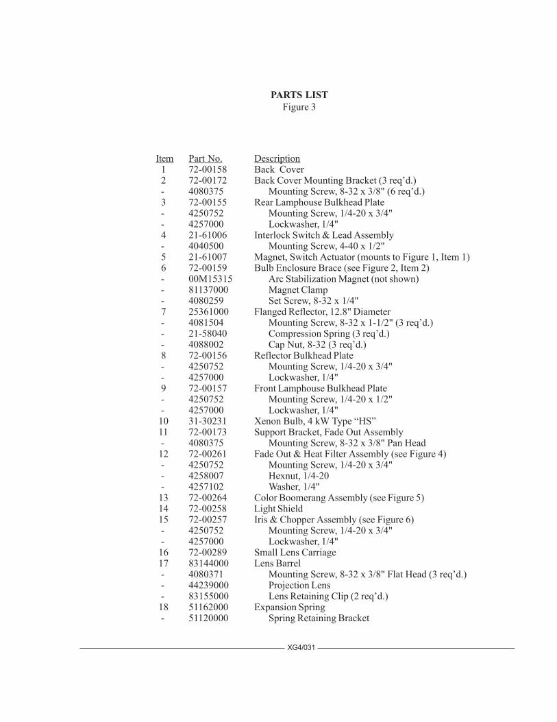
Item Part No. Description 1 72-00158 Back Cover 2 72-00172 Back Cover Mounting Bracket (3 req’d.) - 4080375 Mounting Screw, 8-32 x 3/8" (6 req’d.) 3 72-00155 Rear Lamphouse Bulkhead Plate - 4250752 Mounting Screw, 1/4-20 x 3/4" - 4257000 Lockwasher, 1/4" 4 21-61006 Interlock Switch & Lead Assembly - 4040500 Mounting Screw, 4-40 x 1/2" 5 21-61007 Magnet, Switch Actuator (mounts to Figure 1, Item 1) 6 72-00159 Bulb Enclosure Brace (see Figure 2, Item 2) - 00M15315 Arc Stabilization Magnet (not shown) - 81137000 Magnet Clamp - 4080259 Set Screw, 8-32 x 1/4" 7 25361000 Flanged Reflector, 12.8" Diameter - 4081504 Mounting Screw, 8-32 x 1-1/2" (3 req’d.) - 21-58040 Compression Spring (3 req’d.) - 4088002 Cap Nut, 8-32 (3 req’d.) 8 72-00156 Reflector Bulkhead Plate - 4250752 Mounting Screw, 1/4-20 x 3/4" - 4257000 Lockwasher, 1/4" 9 72-00157 Front Lamphouse Bulkhead Plate - 4250752 Mounting Screw, 1/4-20 x 1/2" - 4257000 Lockwasher, 1/4" 10 31-30231 Xenon Bulb, 4 kW Type “HS” 11 72-00173 Support Bracket, Fade Out Assembly - 4080375 Mounting Screw, 8-32 x 3/8" Pan Head 12 72-00261 Fade Out & Heat Filter Assembly (see Figure 4) - 4250752 Mounting Screw, 1/4-20 x 3/4" - 4258007 Hexnut, 1/4-20 - 4257102 Washer, 1/4" 13 72-00264 Color Boomerang Assembly (see Figure 5) 14 72-00258 Light Shield 15 72-00257 Iris & Chopper Assembly (see Figure 6) - 4250752 Mounting Screw, 1/4-20 x 3/4" - 4257000 Lockwasher, 1/4" 16 72-00289 Small Lens Carriage 17 83144000 Lens Barrel - 4080371 Mounting Screw, 8-32 x 3/8" Flat Head (3 req’d.) - 44239000 Projection Lens - 83155000 Lens Retaining Clip (2 req’d.) 18 51162000 Expansion Spring - 51120000 Spring Retaining Bracket
XG4/031
PARTS LISTFigure 3
XG4/032
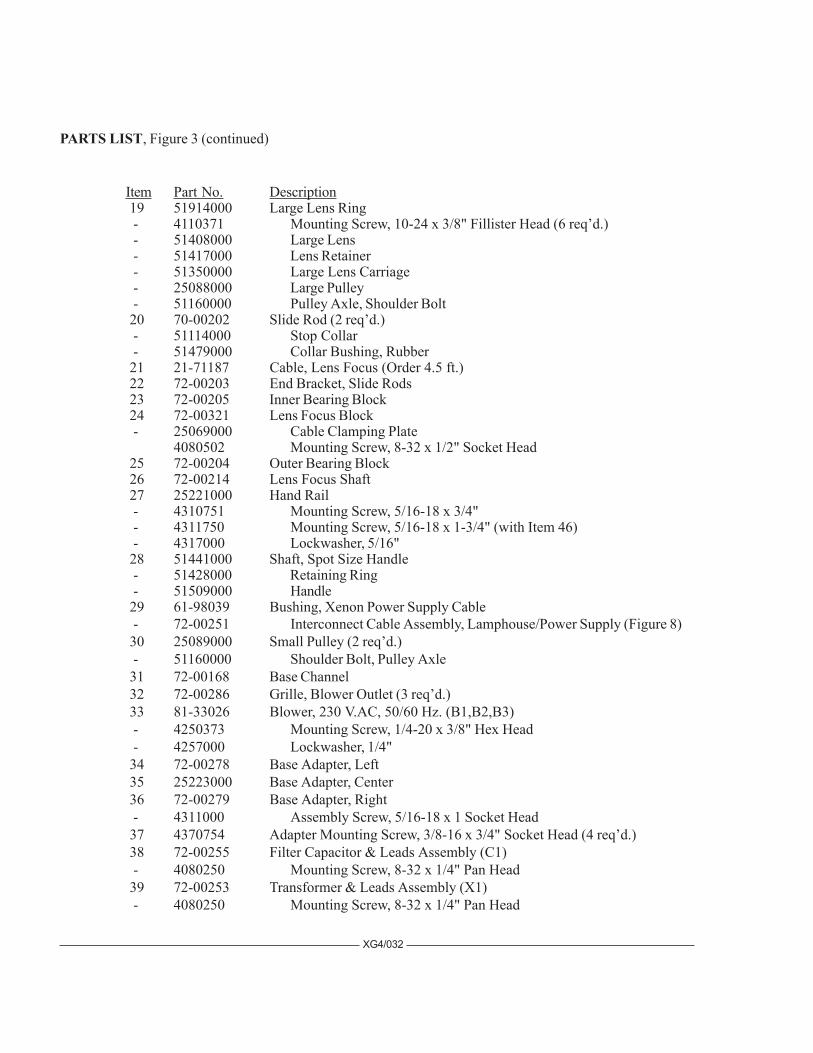
Item Part No. Description 19 51914000 Large Lens Ring - 4110371 Mounting Screw, 10-24 x 3/8" Fillister Head (6 req’d.) - 51408000 Large Lens - 51417000 Lens Retainer - 51350000 Large Lens Carriage - 25088000 Large Pulley - 51160000 Pulley Axle, Shoulder Bolt 20 70-00202 Slide Rod (2 req’d.) - 51114000 Stop Collar - 51479000 Collar Bushing, Rubber 21 21-71187 Cable, Lens Focus (Order 4.5 ft.) 22 72-00203 End Bracket, Slide Rods 23 72-00205 Inner Bearing Block 24 72-00321 Lens Focus Block - 25069000 Cable Clamping Plate
4080502 Mounting Screw, 8-32 x 1/2" Socket Head 25 72-00204 Outer Bearing Block 26 72-00214 Lens Focus Shaft 27 25221000 Hand Rail - 4310751 Mounting Screw, 5/16-18 x 3/4" - 4311750 Mounting Screw, 5/16-18 x 1-3/4" (with Item 46) - 4317000 Lockwasher, 5/16" 28 51441000 Shaft, Spot Size Handle - 51428000 Retaining Ring - 51509000 Handle 29 61-98039 Bushing, Xenon Power Supply Cable - 72-00251 Interconnect Cable Assembly, Lamphouse/Power Supply (Figure 8) 30 25089000 Small Pulley (2 req’d.) - 51160000 Shoulder Bolt, Pulley Axle 31 72-00168 Base Channel 32 72-00286 Grille, Blower Outlet (3 req’d.) 33 81-33026 Blower, 230 V.AC, 50/60 Hz. (B1,B2,B3) - 4250373 Mounting Screw, 1/4-20 x 3/8" Hex Head - 4257000 Lockwasher, 1/4" 34 72-00278 Base Adapter, Left 35 25223000 Base Adapter, Center 36 72-00279 Base Adapter, Right - 4311000 Assembly Screw, 5/16-18 x 1 Socket Head 37 4370754 Adapter Mounting Screw, 3/8-16 x 3/4" Socket Head (4 req’d.) 38 72-00255 Filter Capacitor & Leads Assembly (C1) - 4080250 Mounting Screw, 8-32 x 1/4" Pan Head 39 72-00253 Transformer & Leads Assembly (X1) - 4080250 Mounting Screw, 8-32 x 1/4" Pan Head
PARTS LIST, Figure 3 (continued)
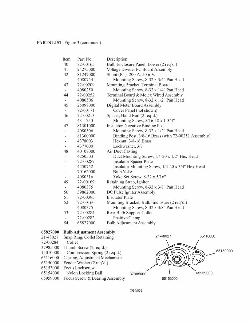
65827000 Bulb Adjustment Assembly21-48027 Snap Ring, Collet Retaining72-00284 Collet37985000 Thumb Screw (2 req’d.)15010000 Compression Spring (2 req’d.)65116000 Casting, Adjustment Mechanism65150000 Fender Washer (2 req’d.)65153000 Focus Lockscrew65154000 Nylon Locking Ball65959000 Focus Screw & Bearing Assembly
XG4/033
Item Part No. Description 40 72-00165 Bulb Enclosure Panel, Lower (2 req’d.) 41 24275000 Voltage Divider PC Board Assembly 42 81247000 Shunt (R1), 200 A. 50 mV. - 4080754 Mounting Screw, 8-32 x 3/4" Pan Head 43 72-00209 Mounting Bracket, Terminal Board - 4080250 Mounting Screw, 8-32 x 1/4" Pan Head 44 72-00252 Terminal Board & Molex Wired Assembly - 4080506 Mounting Screw, 8-32 x 1/2" Pan Head 45 25098000 Digital Meter Board Assembly - 72-00171 Cover Panel (not shown) 46 72-00213 Spacer, Hand Rail (2 req’d.) - 4311750 Mounting Screw, 5/16-18 x 1-3/4" 47 81301000 Insulator, Negative Binding Post - 4080506 Mounting Screw, 8-32 x 1/2" Pan Head - 81300000 Binding Post, 3/8-16 Brass (with 72-00251 Assembly) - 4378003 Hexnut, 3/8-16 Brass - 4377000 Lockwasher, 3/8" 48 40107000 Air Duct Casting - 4250503 Duct Mounting Screw, 1/4-20 x 1/2" Hex Head - 72-00287 Insulator Spacer Plate - 4250752 Insulator Mounting Screw, 1/4-20 x 3/4" Hex Head - 70162000 Bulb Yoke - 4080316 Yoke Set Screw, 8-32 x 5/16" 49 72-00169 Retaining Strap, Igniter - 4080375 Mounting Screw, 8-32 x 3/8" Pan Head 50 39862000 DC Pulse Igniter Assembly 51 72-00395 Insulator Plate 52 72-00160 Mounting Bracket, Bulb Enclosure (2 req’d.) - 4080375 Mounting Screw, 8-32 x 3/8" Pan Head 53 72-00284 Rear Bulb Support Collet - 72-00282 Positive Clamp 54 65827000 Bulb Adjustment Assembly
37985000
6511600021-48027
65150000
6595900065153000
PARTS LIST, Figure 3 (continued)
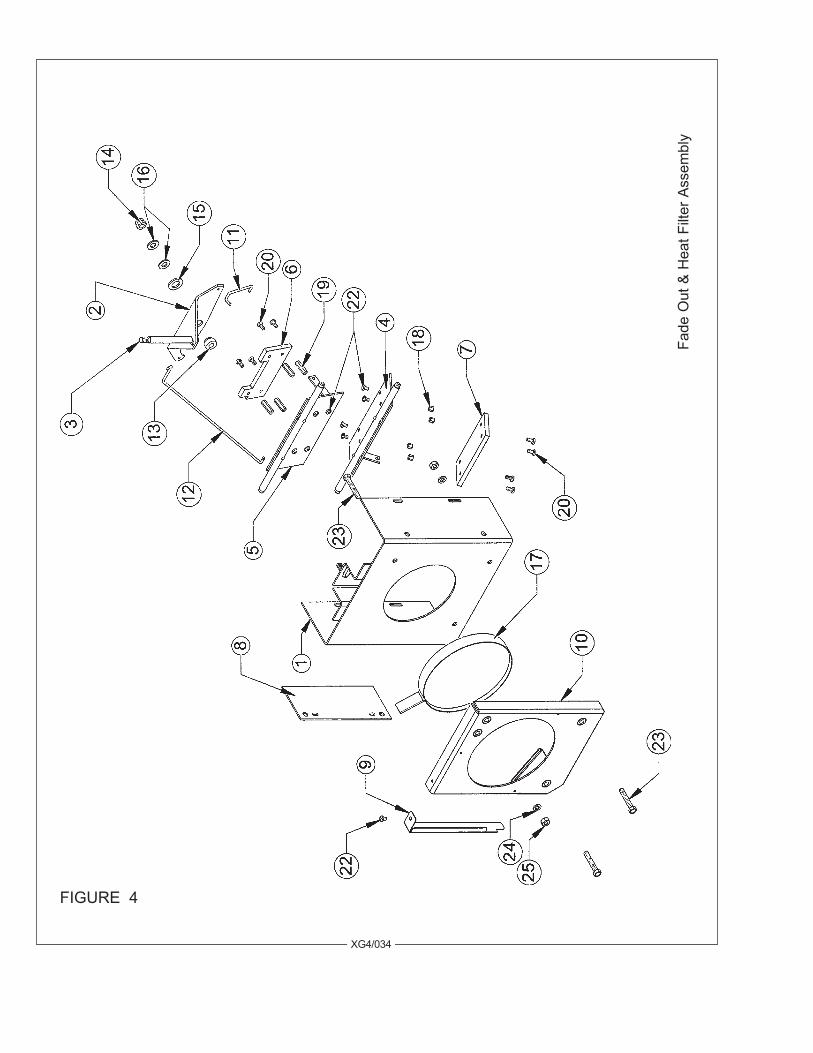
FIGURE 4
XG4/034
Fade
Out
& H
eat F
ilter
Ass
embl
y

Item Part No. Description 1 72-00212 Fade Out Housing, Welded Assembly 2 72-00262 Bell Crank, Fade Out Dousers 3 51155000 Control Lever, Fade Out - 4257102 Flatwasher, 1/4" SAE - 4258001 Hexnut, 1/4-20 4 72-00268 Lower Douser Blade Assembly 5 72-00265 Upper Douser Blade Assembly 6 72-00272 Heat Shield, Upper Blade 7 72-00271 Heat Shield, Lower Blade 8 83351000 Pivot Adjusting Plate, Douser Blades - 4100503 Mounting Screw, 10-32 x 1/2" 9 24332000 Cover Shield, Heat Filter 10 81847000 Heat Filter Holder, Welded Assembly 11 72-00273 Pull Rod, Short 12 72-00274 Pull Rod, Long - 01704000 Hitch Pin, Pull Rods (not shown; 4 req’d.) 13 51153000 Spacer Bushing 14 4318004 Lock Nut, 5/16-18 Hex 15 4507106 Washer, 1/2" Brass 16 4317102 Washer, 5/16" SAE (2 req’d.) 17 72-00504 Heat Filter & Ring Assembly 18 41-98003 Stand-Off, 1/4" Hex (4 req’d.) 19 51-56016 Stand-Off, 7/8" (4 req’d.) 20 4080375 Mounting Screw, 8-32 x 3/8" Pan Head 22 4080250 Mounting Screw, 8-32 x 1/4" Pan Head 23 4251500 Mounting Screw, 1/4-20 x 1-1/2" Hex Head (3 req’d.) 24 4257001 Lockwasher, 1/4" 25 4258001 Hexnut, 1/4-20
PARTS LISTFigure 4
XG4/035
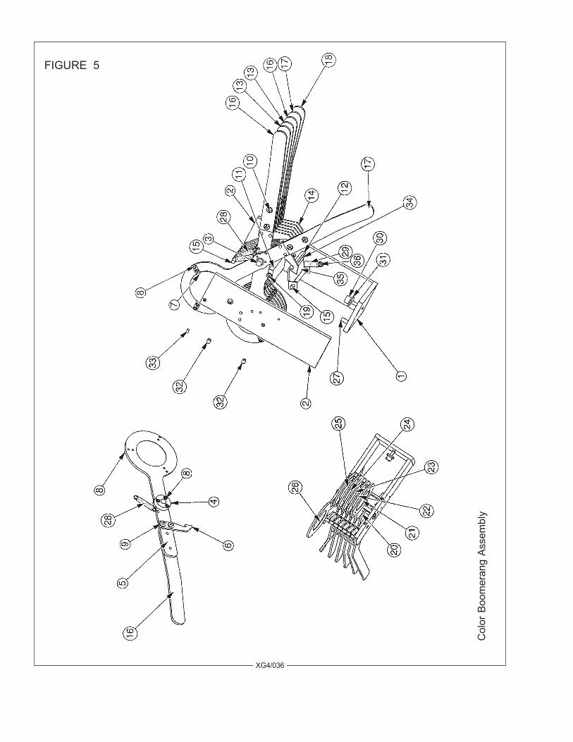
FIGURE 5
XG4/036
Col
or B
oom
eran
g As
sem
bly
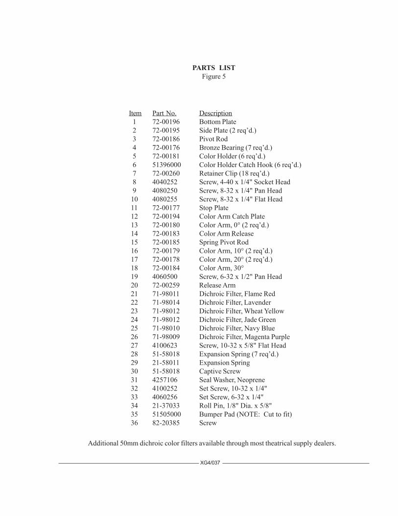
PARTS LISTFigure 5
XG4/037
Item Part No. Description 1 72-00196 Bottom Plate 2 72-00195 Side Plate (2 req’d.) 3 72-00186 Pivot Rod 4 72-00176 Bronze Bearing (7 req’d.) 5 72-00181 Color Holder (6 req’d.) 6 51396000 Color Holder Catch Hook (6 req’d.) 7 72-00260 Retainer Clip (18 req’d.) 8 4040252 Screw, 4-40 x 1/4" Socket Head 9 4080250 Screw, 8-32 x 1/4" Pan Head 10 4080255 Screw, 8-32 x 1/4" Flat Head 11 72-00177 Stop Plate 12 72-00194 Color Arm Catch Plate 13 72-00180 Color Arm, 0° (2 req’d.) 14 72-00183 Color Arm Release 15 72-00185 Spring Pivot Rod 16 72-00179 Color Arm, 10° (2 req’d.) 17 72-00178 Color Arm, 20° (2 req’d.) 18 72-00184 Color Arm, 30° 19 4060500 Screw, 6-32 x 1/2" Pan Head 20 72-00259 Release Arm 21 71-98011 Dichroic Filter, Flame Red 22 71-98014 Dichroic Filter, Lavender 23 71-98012 Dichroic Filter, Wheat Yellow 24 71-98012 Dichroic Filter, Jade Green 25 71-98010 Dichroic Filter, Navy Blue 26 71-98009 Dichroic Filter, Magenta Purple 27 4100623 Screw, 10-32 x 5/8" Flat Head 28 51-58018 Expansion Spring (7 req’d.) 29 21-58011 Expansion Spring 30 51-58018 Captive Screw 31 4257106 Seal Washer, Neoprene 32 4100252 Set Screw, 10-32 x 1/4" 33 4060256 Set Screw, 6-32 x 1/4" 34 21-37033 Roll Pin, 1/8" Dia. x 5/8" 35 51505000 Bumper Pad (NOTE: Cut to fit) 36 82-20385 Screw
Additional 50mm dichroic color filters available through most theatrical supply dealers.
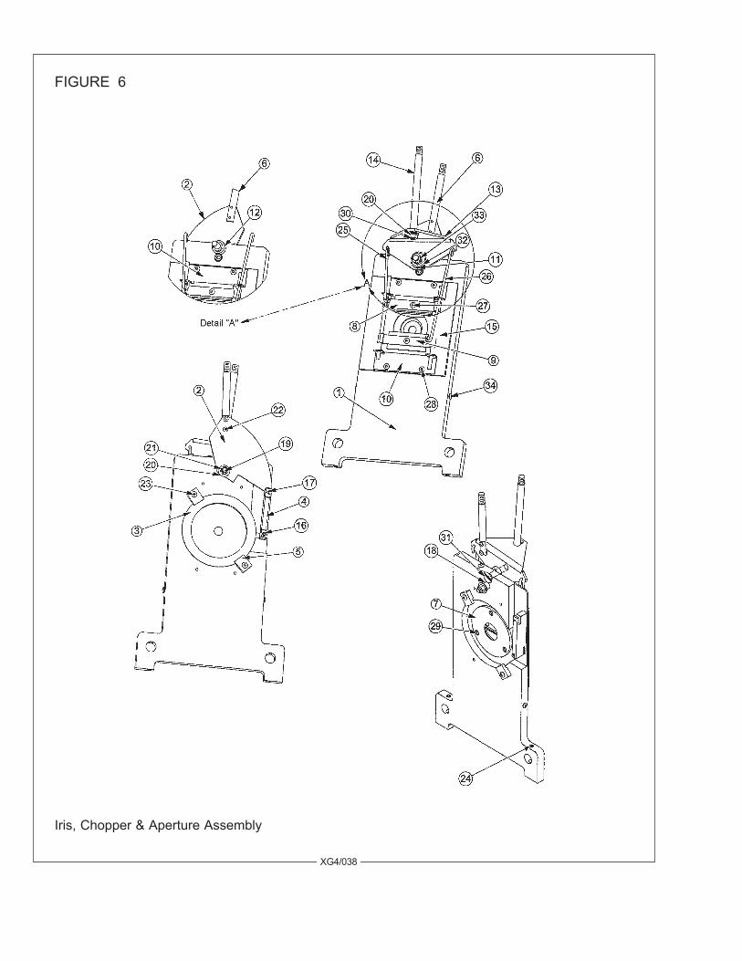
XG4/038
FIGURE 6
Iris, Chopper & Aperture Assembly
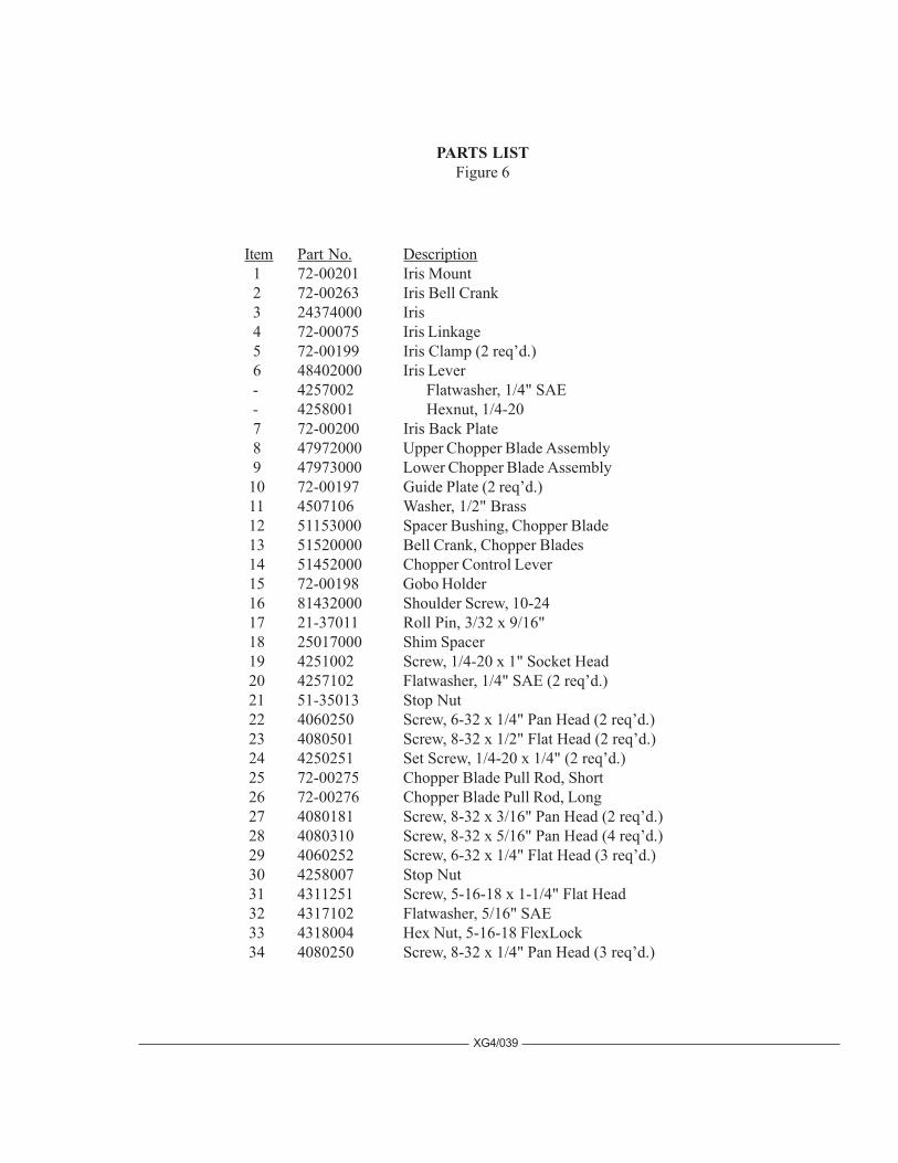
PARTS LISTFigure 6
Item Part No. Description 1 72-00201 Iris Mount 2 72-00263 Iris Bell Crank 3 24374000 Iris 4 72-00075 Iris Linkage 5 72-00199 Iris Clamp (2 req’d.) 6 48402000 Iris Lever - 4257002 Flatwasher, 1/4" SAE - 4258001 Hexnut, 1/4-20 7 72-00200 Iris Back Plate 8 47972000 Upper Chopper Blade Assembly 9 47973000 Lower Chopper Blade Assembly 10 72-00197 Guide Plate (2 req’d.) 11 4507106 Washer, 1/2" Brass 12 51153000 Spacer Bushing, Chopper Blade 13 51520000 Bell Crank, Chopper Blades 14 51452000 Chopper Control Lever 15 72-00198 Gobo Holder 16 81432000 Shoulder Screw, 10-24 17 21-37011 Roll Pin, 3/32 x 9/16" 18 25017000 Shim Spacer 19 4251002 Screw, 1/4-20 x 1" Socket Head 20 4257102 Flatwasher, 1/4" SAE (2 req’d.) 21 51-35013 Stop Nut 22 4060250 Screw, 6-32 x 1/4" Pan Head (2 req’d.) 23 4080501 Screw, 8-32 x 1/2" Flat Head (2 req’d.) 24 4250251 Set Screw, 1/4-20 x 1/4" (2 req’d.) 25 72-00275 Chopper Blade Pull Rod, Short 26 72-00276 Chopper Blade Pull Rod, Long 27 4080181 Screw, 8-32 x 3/16" Pan Head (2 req’d.) 28 4080310 Screw, 8-32 x 5/16" Pan Head (4 req’d.) 29 4060252 Screw, 6-32 x 1/4" Flat Head (3 req’d.) 30 4258007 Stop Nut 31 4311251 Screw, 5-16-18 x 1-1/4" Flat Head 32 4317102 Flatwasher, 5/16" SAE 33 4318004 Hex Nut, 5-16-18 FlexLock 34 4080250 Screw, 8-32 x 1/4" Pan Head (3 req’d.)
XG4/039
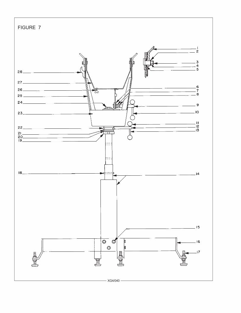
FIGURE 7
XG4/040
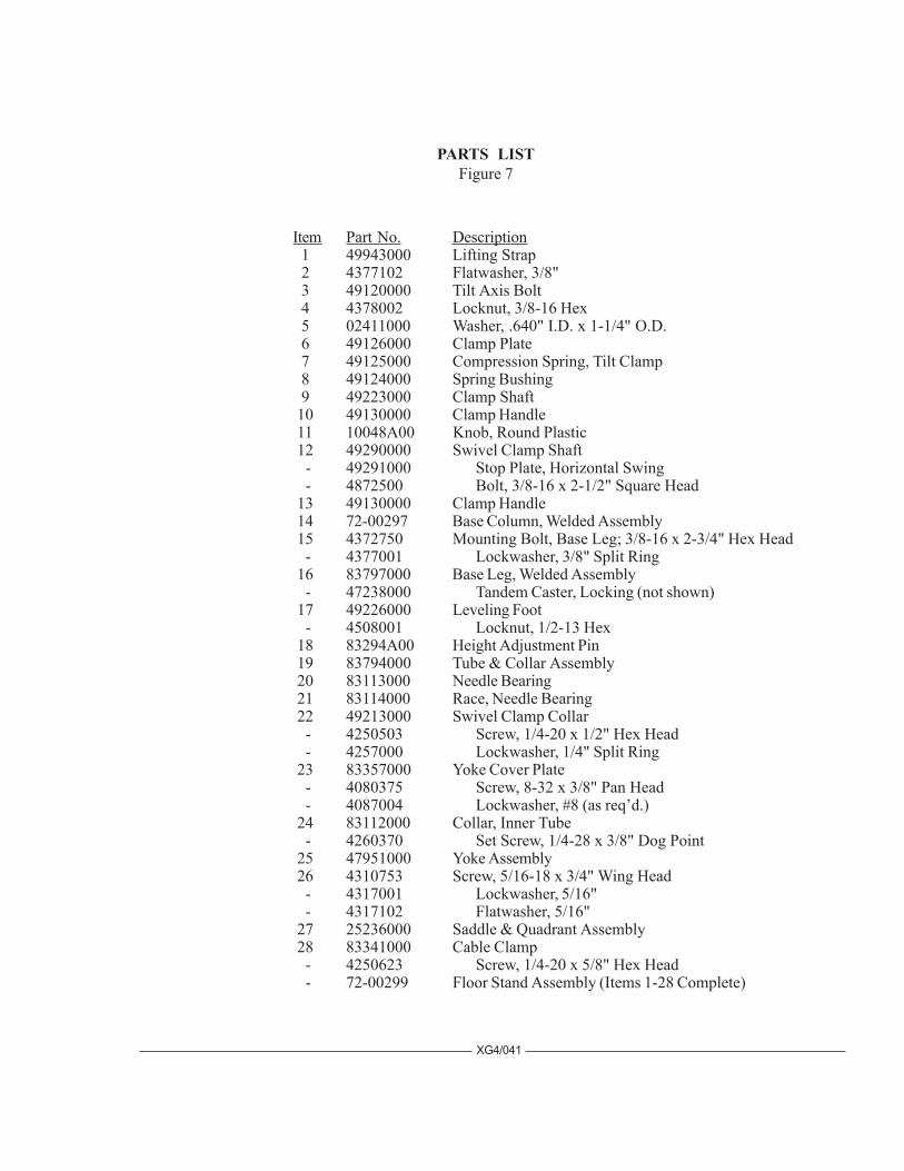
PARTS LISTFigure 7
XG4/041
Item Part No. Description 1 49943000 Lifting Strap 2 4377102 Flatwasher, 3/8" 3 49120000 Tilt Axis Bolt 4 4378002 Locknut, 3/8-16 Hex 5 02411000 Washer, .640" I.D. x 1-1/4" O.D. 6 49126000 Clamp Plate 7 49125000 Compression Spring, Tilt Clamp 8 49124000 Spring Bushing 9 49223000 Clamp Shaft 10 49130000 Clamp Handle 11 10048A00 Knob, Round Plastic 12 49290000 Swivel Clamp Shaft - 49291000 Stop Plate, Horizontal Swing - 4872500 Bolt, 3/8-16 x 2-1/2" Square Head 13 49130000 Clamp Handle 14 72-00297 Base Column, Welded Assembly 15 4372750 Mounting Bolt, Base Leg; 3/8-16 x 2-3/4" Hex Head - 4377001 Lockwasher, 3/8" Split Ring 16 83797000 Base Leg, Welded Assembly - 47238000 Tandem Caster, Locking (not shown) 17 49226000 Leveling Foot - 4508001 Locknut, 1/2-13 Hex 18 83294A00 Height Adjustment Pin 19 83794000 Tube & Collar Assembly 20 83113000 Needle Bearing 21 83114000 Race, Needle Bearing 22 49213000 Swivel Clamp Collar - 4250503 Screw, 1/4-20 x 1/2" Hex Head - 4257000 Lockwasher, 1/4" Split Ring 23 83357000 Yoke Cover Plate - 4080375 Screw, 8-32 x 3/8" Pan Head - 4087004 Lockwasher, #8 (as req’d.) 24 83112000 Collar, Inner Tube - 4260370 Set Screw, 1/4-28 x 3/8" Dog Point 25 47951000 Yoke Assembly 26 4310753 Screw, 5/16-18 x 3/4" Wing Head - 4317001 Lockwasher, 5/16" - 4317102 Flatwasher, 5/16" 27 25236000 Saddle & Quadrant Assembly 28 83341000 Cable Clamp - 4250623 Screw, 1/4-20 x 5/8" Hex Head - 72-00299 Floor Stand Assembly (Items 1-28 Complete)

FIGURE 8
LAMPHOUSE CABLE ASSEMBLYPart No. 72-00251
POWER SUPPLY CABLE ASSEMBLYPart No.62-70025
See Page XG4/004 for Connector Pinout
XG4/042