Embed Size (px)
Citation preview

Material Science - A
MATERIAL SCIENCE A XE

Material Science
© Career Avenues A 2
Structure
Material Science
© Career Avenues A 3
CHAPTER 1
INTRODUCTION
1. CLASSIFICATION OF MATERIALS
Like many other things, materials are classified in groups, so that our brain can
handle the complexity. One can classify them based on many criteria, for example
crystal structure (arrangement of atoms and bonds between them), or properties, or
use. Metals, Ceramics, Polymers, Composites, Semiconductors, and Biomaterials
constitute the main classes of present engineering materials.
Metals
These materials are characterized by high thermal and electrical conductivity;
strong yet deformable under applied mechanical loads; opaque to light (shiny if
polished). These characteristics are due to valence electrons that are detached from
atoms, and spread in an electron sea that glues the ions together, i.e. atoms are
bound together by metallic bonds and weaker van der Waalls forces. Pure metals
are not good enough for many applications, especially structural applications. Thus
metals are used in alloy form i.e. a metal mixed with another metal to improve the
desired qualities. E.g.: aluminum, steel, brass, gold.
Ceramics
These are inorganic compounds, and usually made either of oxides, carbides,
nitrides, or silicates of metals. Ceramics are typically partly crystalline and partly
amorphous. Atoms (ions often) in ceramic materials behave mostly like either
positive or negative ions, and are bound by very strong Coulomb forces between
them. These materials are characterized by very high strength under compression
low ductility; usually insulators to heat and electricity. Examples: glass, porcelain,
many minerals.
Polymers
Polymers in the form of thermo-plastics (nylon, polyethylene, polyvinyl chloride,
rubber, etc.) consist of molecules that have covalent bonding within each molecule

Material Science
© Career Avenues A 4
and van der Waals forces between them. Polymers in the form of thermo-sets (e.g.,
epoxy, phenolics, etc.) consist of a network of covalent bonds. They are based on H,
C and other non-metallic elements. Polymers are amorphous, except for a minority
of thermoplastics. Due to the kind of bonding, polymers are typically electrical and
thermal insulators. However, conducting polymers can be obtained by doping, and
conducting polymer-matrix composites can be obtained by the use of conducting
fillers. They decompose at moderate temperatures (100 – 400° C), and are
lightweight. Other properties vary greatly.
Composite materials
Composite materials are multiphase materials obtained by artificial combination of
different materials to attain properties that the individual components cannot
attain. An example is a lightweight brake disc obtained by embedding SiC particles
in Al-alloy matrix. Another example is reinforced cement concrete, a structural
composite obtained by combining cement (the matrix, i.e., the binder, obtained by a
reaction known as hydration, between cement and water), sand (fine aggregate),
gravel (coarse aggregate), and, thick steel fibers. However, there are some natural
composites available in nature, for example – wood. In general, composites are
classified according to their matrix materials. The main classes of composites are
metal-matrix, polymer-matrix, and ceramic-matrix.
Semiconductors
Semiconductors are covalent in nature. Their atomic structure is characterized by
the highest occupied energy band (the valence band, where the valence electrons
reside energetically) full such that the energy gap between the top of the valence
band and the bottom of the empty energy band (the conduction band) is small
enough for some fraction of the valence electrons to be excited from the valence
band to the conduction band by thermal, optical, or other forms of energy. Their
electrical properties depend extremely strongly on minute proportions of
contaminants. They are usually doped in order to enhance electrical conductivity.
They are used in the form of single crystals without dislocations because grain
boundaries and dislocations would degrade electrical behavior. They are opaque to

Material Science
© Career Avenues A 5
visible light but transparent to the infrared. Examples: silicon (Si), germanium (Ge),
and gallium arsenide (GaAs, a compound semiconductor).
Biomaterials
These are any type material that can be used for replacement of damaged or
diseased human body parts. Primary requirement of these materials is that they
must be biocompatible with body tissues, and must not produce toxic substances.
Other important material factors are: ability to support forces; low friction, wear,
density, and cost; reproducibility. Typical applications involve heart valves, hip
joints, dental implants, intraocular lenses. Examples: Stainless steel, Co-28Cr-6Mo,
Ti-6Al-4V, ultra high molecular weight poly-ethelene, high purity dense Al-oxide,
etc.
ATOMIC STRUCTURE AND ATOMIC BONDING IN SOLIDS
Atomic Structure
Atoms are composed of electrons, protons, and neutrons. Electrons and protons are
negative and positive charged particles respectively. The magnitude of each charged
particle in an atom is 1.6 x 10⁻¹⁹ Coulombs.
The mass of the electron is negligible with respect to those of the proton and the
neutron, which form the nucleus of the atom. The unit of mass is an atomic mass
unit (amu) = 1.66 x 10⁻²⁷ kg, and equals 1/12 the mass of a carbon atom. The
Carbon nucleus has Z=6, and A=6, where Z is the number of protons, and A the
number of neutrons. Neutrons and protons have very similar masses, roughly equal
to 1 amu each. A neutral atom has the same number of electrons and protons, Z.
A mol is the amount of matter that has a mass in grams equal to the atomic mass in
amu of the atoms. Thus, a mole of carbon has a mass of 12 grams. The number of
atoms in a mole is called the Avogadro number, Nav= 6.023 x 10²³. Note that Nav = 1
gram/1 amu.

Material Science
© Career Avenues A 6
Atomic bonding in solids
In order to understand the why materials behave like they do and why they differ in
properties, it is necessary that one should look at atomic level. The study primarily
concentrates on two issues: what made the atoms to cluster together, and how
atoms are arranged. As mentioned in earlier chapter, atoms are bound to each other
by number of bonds. These inter-atomic bonds are primarily of two kinds: Primary
bonds and Secondary bonds. Ionic, Covalent and Metallic bonds are relatively very
strong, and grouped as primary bonds, whereas van der Waals and hydrogen bonds
are relatively weak, and termed as secondary bonds. Metals and Ceramics are
entirely held together by primary bonds - the ionic and covalent bonds in ceramics,
and the metallic and covalent bonds in metals. Although much weaker than
primary bonds, secondary bonds are still very important. They provide the links
between polymer molecules in polyethylene (and other polymers) which make them
solids. Without them, water would boil at -80°C, and life as we know it on earth
would not exist.
Ionic Bonding
This bond exists between two atoms when one of the atoms is negative (has an extra
electron) and another is positive (has lost an electron). Then there is a strong, direct
Coulomb attraction. Basically ionic bonds are non-directional in nature. An example
is NaCl. In the molecule, there are more electrons around Cl, forming Cl- and fewer
electrons around Na, forming Na+. Ionic bonds are the strongest bonds. In real
solids, ionic bonding is usually exists along with covalent bonding.
Schematic representation of ioning bonding. Here, Na is giving an electron to Cl to
have stable structure

Material Science
© Career Avenues A 7
Covalent Bonding
In covalent bonding, electrons are shared between the atoms, to saturate the
valency. The simplest example is the H2 molecule, where the electrons spend more
time in between the nuclei of two atoms than outside, thus producing bonding.
Covalent bonds are stereo-specific i.e. each bond is between a specific pair of atoms,
which share a pair of electrons (of opposite magnetic spins). Typically, covalent
bonds are very strong, and directional in nature. The hardness of diamond is a
result of the fact that each carbon atom is covalently bonded with four neighboring
atoms, and each neighbor is bonded with an equal number of atoms to form a rigid
three-dimensional structure.
Schematic representation of covalent bond in Hydrogen molecule
(sharing of Electrons)
Metallic Bonding
Metals are characterized by high thermal and electrical conductivities. Thus, neither
covalent nor ionic bondings are realized because both types of bonding localize the
valence electrons and preclude conduction. However, strong bonding does occur in
metals. The valence electrons of metals also are delocalized. Thus metallic bonding
can be viewed as metal containing a periodic structure of positive ions surrounded
by a sea of delocalized electrons. The attraction between the two provides the bond,
which is non-directional.
Fluctuating Induced Dipole Bonds
Since the electrons may be on one side of the atom or the other, a dipole is formed:
the + nucleus at the center, and the electron outside. Since the electron moves, the

Material Science
© Career Avenues A 8
dipole fluctuates. This fluctuation in atom A produces a fluctuating electric field
that is felt by the electrons of an adjacent atom, B. Atom B then polarizes so that its
outer electrons are on the side of the atom closest to the + side (or opposite to the -
side) of the dipole in A.
Polar Molecule-Induced Dipole Bonds
Another type of secondary bond exists with asymmetric molecules, also called polar
molecules because of positively and negatively charged regions. A permanent dipole
moment arises from net positive and negative charges that are respectively
associated with the hydrogen and chlorine ends of the HCl molecule, leading to
bonding. The magnitude of this bond will be greater than for fluctuating induced
dipoles.
These two kinds of bonds are also called van der Waals bonds. Third type of
secondary bond is the hydrogen bond. It is categorized separately because it
produces the strongest forces of attraction in this category.
Permanent Dipole Bonds / Hydrogen bonding
It occurs between molecules as covalently bonded hydrogen atoms - for example C-
H, O-H, F-H - share single electron with other atom essentially resulting in
positively charged proton that is not shielded any electrons. This highly positively
charged end of the molecule is capable of strong attractive force with the negative
end of an adjacent molecule. The properties of water are influenced significantly by
the hydrogen bonds/bridges. The bridges are of sufficient strength, and as a
consequence water has the highest melting point of any molecule of its size.
Likewise, its heat of vaporization is very high.
Material Science
© Career Avenues A 9
CHAPTER 2
CRYSTAL STRUCTURE
2.1 DEFINITION OF SOLID
The state of matter that has definition shape and volume is called solid state. Solid
are characterized by incompressibility, rigidity and mechanical strength. It indicates
that in solid state, the constituent particles (atoms, ions or molecules) are closely
packed in some definite geometric arrangement with very small vacant shape or
voids among the neighbouring particles. The constituent particles are held together
by strong force of attraction. The constituent particles vibrate about their mean
position.
2.2 CLASSIFICATION OF SOLID
On the basis of arrangement of constituent particle (atoms/molecules/ions) solid
are divided into three categories
1. Crystalline
2. Polycrystalline
3. Amorphous
Crystalline Solid
The solid whose constituent particles are arranged in a definite pattern
throughout the entire three dimensional network of the crystal are known as
crystalline solids.
They have long range order of constituent particles.
They are isotropic.
They posses very sharp melting point definite geometrical shape and give
clean cleavage of the crystals. They do not lose shapes under their own
weight. Examples are sugar, NaCl, urea, sulphur etc.
Amorphous Solid
The solid whose constituent particles do not possess an ordered arrangement
over a long-range are called amorphous solids.

Material Science
© Career Avenues A 10
Although they possess the properties of incompressibility and rigidity to
certain extent, yet they do not have definite geometrical shapes.
They lose their shape under their own weight, do not posses sharp melting
points also do not give clean cleavage of solid.
They may be regarded as super cooled liquids whose stiffness is due to an
exceptionally high viscosity. They are also called pseudo solids.
Example of amorphous solid is glass, rubber and plastics. These solid are
isotropic in nature, i.e. they have similar physical properties in all the
directions.
The distinction between crystalline and amorphous forms is nicely exhibited in
boron trioxide (B2O3) which can occurs in both crystalline amorphous forms.
Crystalline solid based on the nature of bonding are classified in four main
categories:
Ionic Crystals
In these crystals the icons are held together by strong electrostatic force of
attraction. Each positive and negative charge is held together by certain fixed
number of opposite ions at fixed points in three dimensional spaces. These points
are called lattice points.
Difference between crystalline and amorphous solids
Examples
Crystalline solid Amorphous solid
A 1. The constituent particles
(atoms/molecules/ions) are arranged in
a regular pattern containing short range
as well as long range order.
2. They have sharp melting points all the
bonds are broken at particular
temperature as all bonds are of equal
strength.
3. They are isotropic.
4. They undergone a clean cleavage.
1. The constituent particles
(atoms/molecules/ions) are not arranged in
any regular in any regular pattern, they may
be at the most some short range order only.
2. They melt over a range of temperature as
all the bonds are not equal strength.
3. They are anisotropic.
4. They undergo an irregular cut.
Material Science
© Career Avenues A 11
NaCI is a ionic crystal in which each Na+ ion is surrounded by 6CI-- ions and vice-
versa. Other examples are KNO3, LiF, BaSO4, BaO, MgO etc.
Important characteristics
- They have very high melting point and boiling point.
- Heat of vaporization is very high.
- These solids are hard and brittle.
- Electrical insulator in solid state but conduct electricity in aqueous solution.
Covalent solids
Atoms are held together by a continuous system of covalent linkage. The covalent
bonds extend in two or three dimensions to give rise to a giant network structure.
Examples are diamond, silica, tin, boron nitride, graphite, carborandum, quartz etc.
Important characteristics
- They have generally vey high melting and boiling point.
- Poor conductor of electricity.
- Generally very hard solids.
- Covalent solids does not dissolve in polar solvents.
Metallic solids
In these solids, the lattice points are occupied by kernels (positive ions). These
kernels are immersed in a sea of mobile electron.
Important characteristics
- Quite hard and tough.
- Shining appearance when freshly cut.
- Generally elastic in nature.
- High tensile strength.

Material Science
© Career Avenues A 12
Molecular solids
In these solids, the lattice points are occupied by chargeless molecules. The
intermolecular forces of attraction are hydrogen bonds.
- They are soft solids
- They have low melting and boiling points.
- Volatile solid and high vapour pressure.
- Low heat of vaporization. Non-conductor of electricity.
Polycrystalline Materials
A solid can be composed of many crystalline grains, not aligned with each other. It
is called polycrystalline. The grains can be more or less aligned with respect to each
other. Where they meet is called a grain boundary.
2.3 CRYSTAL STRUCTURE
Crystals are made up of regular and periodic three dimensional pattern of
atoms/ions/molecules in space called crystal structure. Crystal structures are
described in terms of an idealized geometrical concept called space lattice.
The position of constituent atoms, ions or molecules in a crystal relative to one
another in space is represented usually by points. The arrangements of these
points’ shows how the atoms, ions or molecules in a crystal are arranged at different
sites in three dimensional space called space lattice.
2.4 SPACE LATTICE
A space lattice is array of points in space such that the environment about each
pints is same for the sake of simplicity, we first discuss two dimensional
arrangement of point called two dimensional lattice. In the lattice we find that
environment of each point is same. It should be noted that lattice points may or
may not be atoms sites.

Material Science
© Career Avenues A 13
Basis
In the space lattice every lattice point is associated with one or more points (atoms)
called the basis or pattern. When basis is repeated with proper periodicity in all
directions give the actual crystal structure. Thus crystal structure can be imagined
to be lattice array of basis. The basis may contain one two or more atoms. For
example the basis contain three different atoms. The basis itself may or may not
have elements of symmetry.
There are five type of two dimensional lattice namely,
(i) Hexagonal
(ii) Square
(iii) Rectangular
(iv) Rhombic and
(v) Parallelogram lattice.
These differ in symmetry of arrangement of points.
A vector drawn from any lattice point to another is called lattice translation vector
which is a linear combination of two primitive vector.
𝑟 = 𝑥𝑎 + 𝑦𝑏
where x and y are integers. This equation shows that complete two dimensional
lattice may be generated from a lattice points.
A lattice may be divided into cells called basics cell one or more often unit cell in
case or identical atoms in the lattice. A crystal lattice may be generated by
repeating the unit cell after displacement along the axis. The unit cell is
characterized by edge length (a.b) and angle (𝛼) between them.
Full lattice can be generated by repeatedly moving the unit cell in the direction of
edges by the distance equal to the cell edge. For a rhombic lattice, a regular unit cell
with an interior point is normally chosen such a unit cell with interior point is
called centered unit cell. The unit cell which does not contain any interior point is
known as a primitive unit cell.
Material Science
© Career Avenues A 14
2.5 THREE-DIMENSIONAL LATTICE (SPACE LATTICE AND UNIT
CELL)
The crystal lattice or space lattice is the diagrammatic representation of constituent
particles in three-dimensional in which each particles is represented by points.
Thus a regular three dimensional arrangements of points in space is called crystal
lattice.
Unit cell
A unit cell is the smallest portion of crystal lattice which when repeated in different
defection generates the entire lattice. A unit cell may be defined as a polyhedron that
will cover the crystal by application of translation group and exhibits all the properties
of a crystal as a whole.
A unit cell is characterized by edge length a, b along the three edges of unit cell and
angle α, β and γ are the angles between the pairs of edges us a unit cell is
characterized by six parameters a, b, c, a, β and γ. The choice of units cell is made
consistent with the consideration that unit cell must be some integral multiple of
basic cell and it must contain at least one unit( molecule, atoms, ions) of the solid.
2.6 PRIMITIVE AND CENTERED UNIT CELLS
The unit cell are broadly classified in two categories namely primitive and centered
(non-primitive).
Primitive unit cell
A primitive unit cell contains the equivalent of one lattice points. In other words
when constituent particles are present only at the corner position of unit cell it is
called primitive cell. There are seven type of primitive unit cell in crystal.
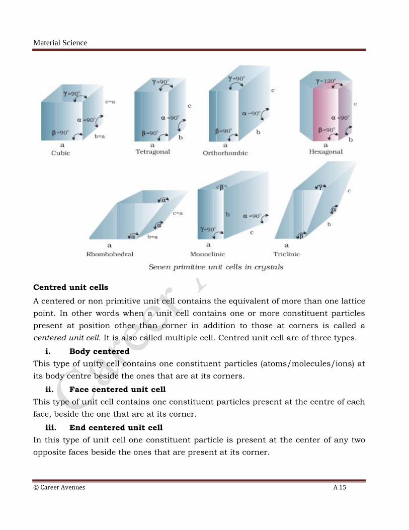
Material Science
© Career Avenues A 15
Centred unit cells
A centered or non primitive unit cell contains the equivalent of more than one lattice
point. In other words when a unit cell contains one or more constituent particles
present at position other than corner in addition to those at corners is called a
centered unit cell. It is also called multiple cell. Centred unit cell are of three types.
i. Body centered
This type of unity cell contains one constituent particles (atoms/molecules/ions) at
its body centre beside the ones that are at its corners.
ii. Face centered unit cell
This type of unit cell contains one constituent particles present at the centre of each
face, beside the one that are at its corner.
iii. End centered unit cell
In this type of unit cell one constituent particle is present at the center of any two
opposite faces beside the ones that are present at its corner.

Material Science
© Career Avenues A 16
There may be possible variation of primitive unit cell as centered unit cells. The
seven primitive unit cell and their possible variation as centered unit cell with
characterized are describe.
It should be noted that theoretically that can be 32 points groups or crystal based
system on different combination of elements of symmetry but on grouping there are
only seven categories known as seven basic crystal systems. It can be shown
mathematically that 32 points groups (crystal system) can further produce 230
space groups(Lattice).
Bravias Lattice
The French mathematician Bravias showed from geometrical consideration that
there can be only 14 different ways in which similar points can be arrangement in
three dimensional space. Thus total number of space lattice belonging to all the
seven crystal system put together is only14. There are known as Bravias lattice. The
units cell of 14 Bravias lattice.

Material Science
© Career Avenues A 17
There are 32 classes of Crystal systems based on geometrical considerations
(i.e, symmetry and internal structure). But it is common practice to divide call
Crystal system into seven groups or basic systems.
The Basic Crystal system are:
(i) Cubic (ii) Tetragonal (ii) Orthorhombic (iv) Monoclinic
(v) Triclinic (iv) Trigonal (vii) Hexagonal
Material Science
© Career Avenues A 18
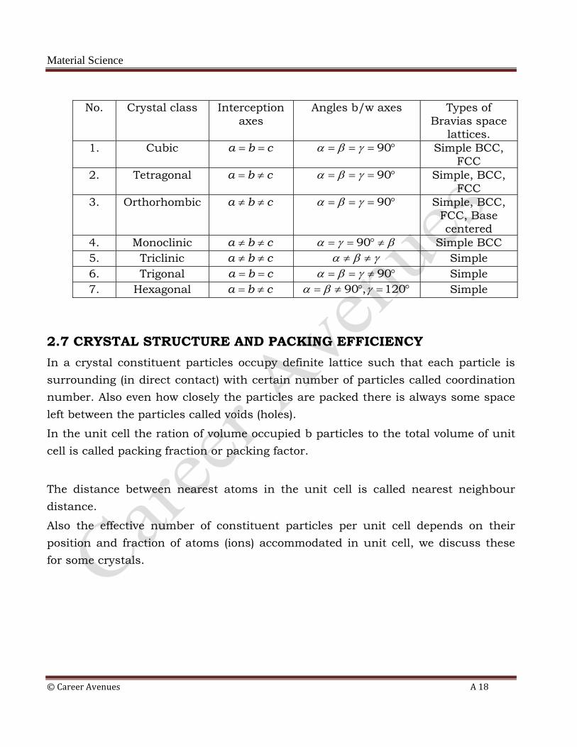
No. Crystal class Interception
axes
Angles b/w axes Types of
Bravias space lattices.
1. Cubic a b c 90 Simple BCC,
FCC
2. Tetragonal a b c 90 Simple, BCC,
FCC
3. Orthorhombic a b c 90 Simple, BCC,
FCC, Base centered
4. Monoclinic a b c 90 Simple BCC
5. Triclinic a b c Simple
6. Trigonal a b c 90 Simple
7. Hexagonal a b c 90 , 120 Simple
2.7 CRYSTAL STRUCTURE AND PACKING EFFICIENCY
In a crystal constituent particles occupy definite lattice such that each particle is
surrounding (in direct contact) with certain number of particles called coordination
number. Also even how closely the particles are packed there is always some space
left between the particles called voids (holes).
In the unit cell the ration of volume occupied b particles to the total volume of unit
cell is called packing fraction or packing factor.
The distance between nearest atoms in the unit cell is called nearest neighbour
distance.
Also the effective number of constituent particles per unit cell depends on their
position and fraction of atoms (ions) accommodated in unit cell, we discuss these
for some crystals.

Material Science
© Career Avenues A 19
2.8 CUBIC CRYSTAL
In the cubic crystal three edges are equal and angle between two faces in 90oThere
are three type of cubic crystal.
Simple cubic structure (primitive)
Structure as eight atoms are arranged in a regular cube one atom at each corner. It
is a cubic unit cell of size ‘a’. The arrangement of atoms is related in all X,Y and Z
direction . It can be observed that each corner atoms shared by 8 lattice i.e., one
corner of lattice contains only 1/8 atoms. The structure of polonium is comes in
this category.
Atomic packing factor
This is also called relative density of packing.
𝐴𝑃𝐹 =𝑁𝑜. 𝑜𝑓 𝑎𝑡𝑜𝑚𝑠 × 𝑣𝑜𝑙𝑢𝑚𝑒 𝑜𝑓 𝑜𝑛𝑒 𝑎𝑡𝑜𝑚
𝑣𝑜𝑙𝑢𝑚𝑒 𝑜𝑓 𝑢𝑛𝑖𝑡 𝑐𝑒𝑙𝑙
Since in case of simple cubic crystal the atoms are present only at corner Therefore
in a simple cubic cell number of atoms per unit cell.
1
8× 8 = 1

Material Science
© Career Avenues A 20
Radius of an atoms =r,
volume of cubic cell= a3=(2r)3
where, a= 2 r
nearest neighbour distance, d= a =2r
𝐴𝑃𝐹 =1 ×
4
3𝜋 𝑟3
(2𝑟)3= 0.52
The side of the unit cell is called as lattice constant.
Body-Centered cubic (BCC) structure
There is one atoms at each corner of the cube and one atoms at the center of the
cube. Such crystal are called BCC crystal.
𝑁𝑢𝑚𝑏𝑒𝑟 𝑜𝑓 𝑎𝑡𝑜𝑚𝑠 𝑎𝑡 𝑎𝑙𝑙 𝑐𝑜𝑟𝑛𝑒𝑟 = 1
𝑁𝑢𝑚𝑏𝑒𝑟 𝑜𝑓 𝑎𝑡𝑜𝑚𝑠 𝑎𝑡 𝑎𝑙𝑙 𝑐𝑜𝑟𝑛𝑒𝑟𝑠 = 1
8× 8 = 1𝑡𝑜𝑡𝑎𝑙 𝑛𝑜. 𝑜𝑓 𝑎𝑡𝑜𝑚𝑠 = 2
𝐵𝑜𝑑𝑦 𝑑𝑖𝑎𝑔𝑜𝑛𝑎𝑙 = 𝑟 + 2𝑟 + 𝑟 = 4𝑟
Now
(𝐵𝑜𝑑𝑦 𝑑𝑖𝑎𝑔𝑜𝑛𝑎𝑙)2 = 𝑆𝑢𝑚 𝑜𝑓 𝑠𝑞𝑢𝑎𝑟𝑒 𝑜𝑓 𝑎𝑙𝑙 𝑡𝑒 𝑡𝑟𝑒𝑒 𝑠𝑖𝑑𝑒𝑠
(4𝑟)2 = 𝑎2 + 𝑎2 + 𝑎2 = 3𝑎2
𝑎 =4𝑟
3
𝐴𝑃𝐹 =2 ×
4
3𝜋𝑟3
4𝑟
3
3 = 0.68

Material Science
© Career Avenues A 21
Face-centered cubic (FCC) structure
There is one atoms in each corner of the cube and one atoms at ht e center of each
face. There is no atom in the center of the cube. Such crystal are called FCC
structure. Copper, aluminium, argon, nickel, gold, platinum, lead, thorium etc. are
of FCC structure. Each face atoms is shared by two units cells or we can say that
one face of the FCC unit cell contain ½ atoms.
𝑁𝑢𝑚𝑏𝑒𝑟 𝑜𝑓 𝑎𝑡𝑜𝑚𝑠 𝑖𝑛 𝑎𝑙𝑙 𝑠𝑖𝑥 𝑓𝑎𝑐𝑒𝑠 =1
2× 6 = 3
𝑁𝑢𝑚𝑏𝑒𝑟 𝑜𝑓 𝑎𝑡𝑜𝑚𝑠 𝑎𝑡 𝑎𝑙𝑙 𝑐𝑜𝑟𝑛𝑒𝑟 =1
8× 8 = 1
𝑡𝑜𝑡𝑎𝑙 𝑛𝑜. 𝑜𝑓 𝑎𝑡𝑜𝑚𝑠 = 4
(4𝑟)2 = 𝑎2 + 𝑎2
𝑎 = 8𝑟
𝐴𝑃𝐹 =4 ×
4
3𝜋𝑟3
8𝑟 3 = 0.74
Thus in FCC arrangement 74 % space is occupied by constituent particles and
26%is empty

Material Science
© Career Avenues A 22
Hexagonal Crystals
It contains one lattice points at each corner of hexagonal face and one at the center
of hexagonal faces.
Each corner atoms is shared by six other unit lattice.
𝑁𝑢𝑚𝑏𝑒𝑟 𝑜𝑓 𝑎𝑡𝑜𝑚𝑠 𝑖𝑛 𝑢𝑝𝑝𝑒𝑟 𝑒𝑥𝑎𝑔𝑜𝑛𝑎𝑙 𝑝𝑙𝑎𝑛𝑒 =1
6× 6 = 1
𝑁𝑢𝑚𝑏𝑒𝑟 𝑜𝑓 𝑎𝑡𝑜𝑚𝑠 𝑖𝑛 𝑙𝑜𝑤𝑒𝑟 𝑒𝑥𝑎𝑔𝑜𝑛𝑎𝑙 𝑝𝑙𝑎𝑛𝑒 =1
6× 6 = 1
Each central atoms is shared by two unit cell. Which means upper and lower planes
contain ½ atoms each.
𝑇𝑜𝑡𝑎𝑙 𝑛𝑢𝑚𝑏𝑒𝑟 𝑜𝑓 𝑐𝑒𝑛𝑡𝑟𝑎𝑙 𝑎𝑡𝑜𝑚𝑠 𝑖𝑛 𝑏𝑜𝑡 𝑢𝑝𝑝𝑒𝑟 𝑎𝑛𝑑 𝑙𝑜𝑤𝑒𝑟 𝑝𝑙𝑎𝑛𝑒𝑠 =1
2× 2 = 1 and three
central atoms. The arrangement is called hexagonal close-packed (hcp) structure
(discussed later). There are three atoms at the interstices between two hexagonal
faces. The total number of atoms inside the cp structure is 6 as calculated.
Total number of atoms in hcp crystal= 1+1+1+ 3=6
A.P.F may be calculated which is found to be 0.74.
The coordination number of hcp structure is12.

Material Science
© Career Avenues A 23
2.9 CLOSE PACKING IN CRYSTAL SOLIDS
The constituent particles of a crystalline solid is said to be closely packed if they
occupy maximum possible space so the state of maximum possible density is
reached. In order to understand the close packing we consider the constituent
particles as rigid spheres.
Close packing in two dimensions
The spheres responding atoms/ions can be arranged side by side to make a line of
spheres which is called a row and row from a crystal plane. The crystal plane can be
formed in two ways.
1. The rows are arranged in such a way that rows have a horizontal as well as
verticals alignment. Such type of packing in two dimension is called square
close packing in two dimension and in this packing one sphere is in direct
contact of four other spheres and sphere occupy 52.4 per cent of space.
2. The rows are arranged in such a way that sphere of successor row are placed
in the depression between the spheres of predecessor row. In such
arrangement one sphere is in direct contact of six spheres and 60.4% space is
occupied by spheres. Such a arrangement in two dimensions is called
hexagonal close packing in two dimension.
Close packing in three dimensions
In order to extend the packing in three dimensions we place layers one over the
other in different ways.
(a) Three dimensional close packing from two dimensional square close packing.
When two dimensional square closed packing layers are placed over the other
in such a way that sphere of upper layer is layers above those of first layers
the resulting 3- dimensional arrangement has AAA—type pattern. The lattice
thus generated is the simple cubic lattice and the unit cell is primitive cubic
unit cell.
(b) Three dimensional close packing from two dimensional hexagonal close
packing.
Material Science
© Career Avenues A 24
In order to understand the more closed packing we take layers of hexagonal close
packing in two dimensional as it is a denser packing than square close packing in
two dimension. As we see that some space is left among spheres. These empty space
are called voids As it is clear from the figure that there two type of voids, upper
triangular marked a and upper triangular marked b. Now the second layer is placed
over first layer in such a way that spheres of second layer are placed over any one
type of voids (a or b) as placing sphere over both a and b type of voids are but
possible. Let us place the spheres of second layer over first layer in such a way that
it lies over void of b type in first layer. So a new type of voids (tetrahedral) marked T
are created.
When second layer is placed in such a way he triangular voids in second layer are
above the triangular voids in first layer and triangular shapes of these voids do not
overlap. A new type of voids is formed called octahedral void (marked O).
Placing third layer over second layer
Now the third layer can also be formed in two ways:
(i) HCP
When the third is placed in such a way that its sphere lie over the new void
T(tetrahedral) then third layer will be identical to first layer and after that
placing fourth layer identical to second.
In this way arrangement will be AB, AB---------- type and known as
hexagonal close packing in three dimension. Metal like Be, Mg, Mo, V,
and Cd Crystallizes in HCP structure.
(ii) Cubic close packing
when third layer over second layer in such a way that spheres of this layer
cover octahedral voids then a different third layer formed and then placing
fourth layer similar to first layer, gives other arrangement of the type
ABCABC---- Which is called cubic closed packing (ccp) and is similar to
FFC arrangement in cubic crystal.

Material Science
© Career Avenues A 25
2.10 INTERSTITIAL SITES CLOSED PACKED STRUCTURE
(a) Trigonal site or void or hole
This is formed when three sphere lie at the vertices of an equilateral triangle.
In this case, 𝑟 = 0.155𝑅
(b) Tetrahedral site or void or hole
When one sphere is placed above the three spheres placed in a plane touching
each other, tetrahedral void is formed. The site is surrounded by 4 spheres
and centres of these sphere lie at the corners of a regular tetrahedron.
In this case, 𝑟 = 0.225𝑅
(c) Octahedral site or void
This hole is surrounded by six closely packed spheres.
In this case, 𝑟 = 0.414𝑅

Material Science
© Career Avenues A 26
(d) Cubic site or hole
This is formed between eight closely packed spheres.
In this case, 𝑟 = 0.732𝑅
2.11 COORDINATION NUMBER
The number of neighbouring particles in direct contact of a particle is called
coordination no. For example, in two dimensional arrangements the coordination
no. for square close packing is four, while for hcp, the coordination no. is 6. In 3-D
arrangement, the C.N. in FCC or HCP is 12 while in BCC is 8.
2.12 RADIUS RATION
𝑅𝑎𝑑𝑖𝑢𝑠 𝑟𝑎𝑡𝑖𝑜 =𝑅𝑎𝑑𝑖𝑢𝑠 𝑜𝑓 𝑐𝑎𝑡𝑖𝑜𝑛
𝑟𝑎𝑑𝑖𝑢𝑠 𝑜𝑓 𝑎𝑛𝑖𝑜𝑛=
𝑟+
𝑟−
Material Science
© Career Avenues A 27
2.13 STRUCTURE OF IONIC CRYSTAL
Structure of Sodium Chloride (NaCl)
The structure is also known as Rock Salt Structure. The salient feature of this
structure are:
i) The Cl- ions being in the six than Na+ ions from cubic close packed
arrangement, i.e., they are located at all the eight corners of the cubic and
also at the center of each face (FFC arrangement).
ii) The Na+ occupies all the octahedral voids. In the cubic unit cell, Na+ ions
are present at the canter each edge of the cube and one Na+ ions is located
at the body canter of cube.
iii) Since there is only one octahedral voids for each cubic closed packed
spheres, so there is only Na+ for each Cl- ion. Thus the stoichiometry of the
crystal is Na+ Cl-.
𝑁𝑢𝑚𝑏𝑒𝑟 𝑜𝑓 𝑓𝑜𝑟𝑚𝑢𝑙𝑎 𝑢𝑛𝑖𝑡𝑠 𝑜𝑓 𝑠𝑜𝑑𝑖𝑢𝑚 𝑐𝑙𝑜𝑟𝑖𝑑𝑒 𝑝𝑒𝑟 𝑢𝑛𝑖𝑡 𝑐𝑒𝑙𝑙
𝑁𝑢𝑚𝑏𝑒𝑟 𝑜𝑓 𝑁𝑎 + 𝑖𝑜𝑛𝑠 𝑝𝑒𝑟 𝑢𝑛𝑖𝑡 𝑐𝑒𝑙𝑙 = 4
𝑁𝑢𝑚𝑏𝑒𝑟 𝑜𝑓 𝐶𝑙 − 𝑖𝑜𝑛𝑠 𝑝𝑒𝑟 𝑢𝑛𝑖𝑡 𝑐𝑒𝑙𝑙 = 4
2.14 CRYSTAL DIRECTIONS, CRYSTAL PLANES AND MILLER
INDICES
For understandings crystallography the concept of direction and planes play an
important role. In a crystal there exist directions and planes which contain large
number of atoms. It is necessary to locate these directions and planes for crystal
analysis.
2.15 CRYSTAL DIRECTIONS
To understand the crystal directions let us first take the case of two dimensions.
The crystal direction is described by writing the first integer point (x,y) in [] though
which the directions line passes. For example the direction OA, OB, OC, OD are
written as [1,2], [1,1], [2,1], [3,1] are respectively.
Material Science
© Career Avenues A 28
In the similar way the crystal direction in three-dimension is written as [x,y,z] where
x,y,z are first integral points corresponding to three mutually perpendicular axes
X,Y,Z respectively.
It is easier to specify crystal direction on a unit cell. Three different directions are
shown in the orthorhombic lattice. The direction [111] is the line passing through
origin and point P. The point p is at a unit ell edge distance from each axis.
The direction [100] is the line passing through origin point Q. The point Q is a
distance of 1,0 0, 1 from X,Y and Z-axis.
In specifying crystal direction, crystal axes are taken base. Directions [333] or [222]
direction are identical to [111] directions. In such cases lowest combination of
integers [111] is used to specifying directions.
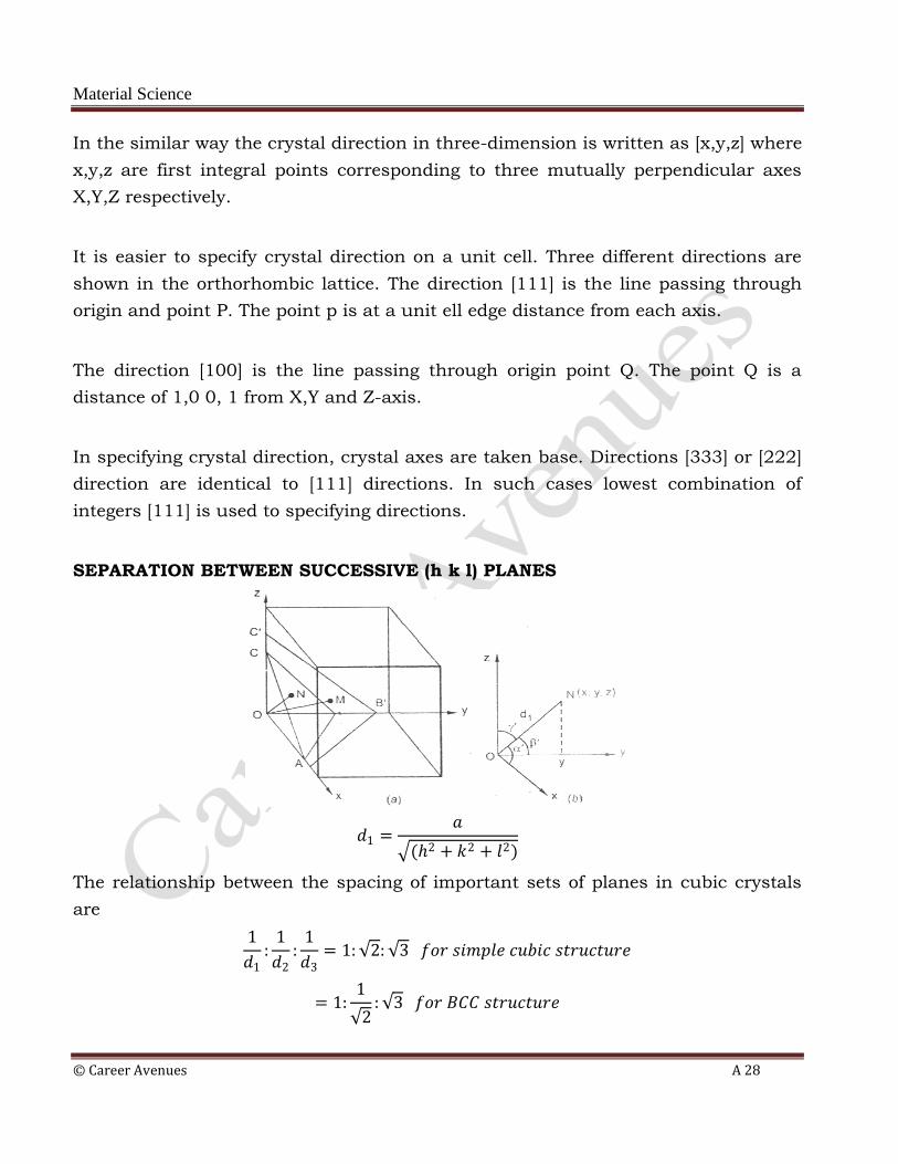
SEPARATION BETWEEN SUCCESSIVE (h k l) PLANES
𝑑1 =𝑎
(2 + 𝑘2 + 𝑙2)
The relationship between the spacing of important sets of planes in cubic crystals
are
1
𝑑1:
1
𝑑2:
1
𝑑3= 1: 2: 3 𝑓𝑜𝑟 𝑠𝑖𝑚𝑝𝑙𝑒 𝑐𝑢𝑏𝑖𝑐 𝑠𝑡𝑟𝑢𝑐𝑡𝑢𝑟𝑒
= 1:1
2: 3 𝑓𝑜𝑟 𝐵𝐶𝐶 𝑠𝑡𝑟𝑢𝑐𝑡𝑢𝑟𝑒

Material Science
© Career Avenues A 29
= 1: 2: 3
2 𝑓𝑜𝑟 𝐹𝐶𝐶 𝑠𝑡𝑟𝑢𝑐𝑡𝑢𝑟𝑒
2.16 LAW OF RATIONAL INDICES
This law state that intercepts of any face of a crystal along the crystallographic axis
are either equal to unit intercepts (a, b, c) or some simple whole number multiples
of them.
If OX, OY and OZ represent, crystallographic axes and ABC is unit plane having
intercepts a, b, c on crystallographic axes respectively. Then as per law of rational
indices the intercepts of plane KLM will be n1 a, n2 b, n3 c where n1, n2 , n3 are
positive integer.
2.17 CRYSTALLOGRAPHIC PLANES
The crystal lattice may be regarded as made-up of parallel equidistant planes
passing through lattice point which are known as lattice planes.
For a given lattice the lattice points on lattice planes can be chosen in different
ways.
These plane are also called crystallographic- planes or atomic planes. These planes
and crystal direction play an important role in hardness, plastic deformation and
other properties. Some of the crystallographic planes for cubic crystal are shown.
2.18 LINEAR DENSITY AND PLANER DENSITY
Linear Density (LD)
It is defined as number of atoms per unit length whose centres lie on the direction
vector for specific crystallographic direction.
𝐿𝐷 =𝑁𝑜. 𝑜𝑓 𝑎𝑡𝑜𝑚𝑠 𝑐𝑒𝑛𝑡𝑟𝑒𝑑 𝑜𝑛 𝑑𝑖𝑟𝑒𝑐𝑡𝑖𝑜𝑛 𝑣𝑒𝑐𝑡𝑜𝑟
𝑙𝑒𝑛𝑔𝑡 𝑜𝑓 𝑑𝑖𝑟𝑒𝑐𝑡𝑖𝑜𝑛 𝑣𝑒𝑐𝑡𝑜𝑟
The unit for linear density are reciprocal of length (m-1,nm-1)

Material Science
© Career Avenues A 30
Planer density (PD)
The planer density of a crystal is the density of atoms in a crystal plane. It is defined
as the number of atoms per units area. The unit of planar density is reciprocal of
area (m-1, nm-1)
𝑃𝐷 =𝑁𝑜. 𝑜𝑓 𝑎𝑡𝑜𝑚𝑠 𝑖𝑛 𝑎 𝑝𝑙𝑎𝑛𝑒
𝑡𝑒 𝑎𝑟𝑒𝑎 𝑜𝑓 𝑡𝑒 𝑝𝑙𝑎𝑛𝑒
2.19 MILLER INDICES
Miller evolved a method a crystal plane or direction. In this method to represent a
crystal plane a set of three integers h, k, l are written with in parentheses as (h, k, l)
Similarly crystal direction is represented as a set of three number written with in
the square brackets [u, v, w]. The miller indices of a crystal inversely proportional to
the intercepts of that face on the axes.
Miller indices are used to designate the relation of a certain set planes to the axes of
unit cell. One corner of the crystal is assumed to be the origin of space coordinates
and any set of plane given by reciprocals of its smallest intersection with these
coordinates. The unit of coordinates is taken as lattice parameters of the crystal. If a
plane is parallel to certain axis. It (plane) intersects the axis at∞.
Method to find the Miller Indices of Plane
To find out the miller indices of a given plane, the following steps are to be followed.
1. The intercepts made by the plane along x, y and z axes are noted.
2. The coefficients of the intercepts are noted separately.
3. Inverse of these coefficients are taken.
4. The fraction are multiplied by a suitable number, so that all the fraction
become integers.
5. Write the integers within the parentheses which is the Miller indices for the
plane.
6. The positive X-axis is represented as (100) Y-axis as )(010) and Z-axis as
(001). Similarly the negative X-axis as (100) negative Y-axis as (010) and
negative Z-axis as (001).
Material Science
© Career Avenues A 31
Important Feature of the Miller Indices
The miller index notion is especially useful for cubic system. Its desirable features
are:
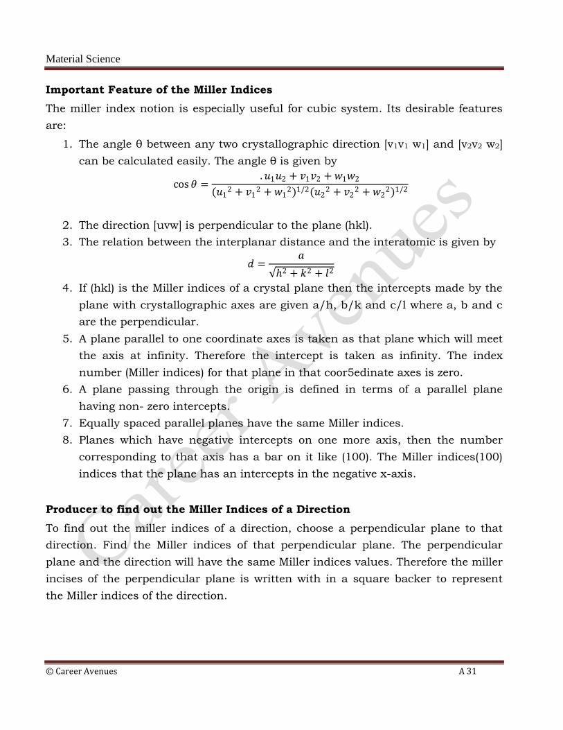
1. The angle θ between any two crystallographic direction [v1v1 w1] and [v2v2 w2]
can be calculated easily. The angle θ is given by
cos 𝜃 =.𝑢1𝑢2 + 𝑣1𝑣2 + 𝑤1𝑤2
(𝑢12 + 𝑣1
2 + 𝑤12)1/2(𝑢2
2 + 𝑣22 + 𝑤2
2)1/2
2. The direction [uvw] is perpendicular to the plane (hkl).
3. The relation between the interplanar distance and the interatomic is given by
𝑑 =𝑎
2 + 𝑘2 + 𝑙2
4. If (hkl) is the Miller indices of a crystal plane then the intercepts made by the
plane with crystallographic axes are given a/h, b/k and c/l where a, b and c
are the perpendicular.
5. A plane parallel to one coordinate axes is taken as that plane which will meet
the axis at infinity. Therefore the intercept is taken as infinity. The index
number (Miller indices) for that plane in that coor5edinate axes is zero.
6. A plane passing through the origin is defined in terms of a parallel plane
having non- zero intercepts.
7. Equally spaced parallel planes have the same Miller indices.
8. Planes which have negative intercepts on one more axis, then the number
corresponding to that axis has a bar on it like (100). The Miller indices(100)
indices that the plane has an intercepts in the negative x-axis.
Producer to find out the Miller Indices of a Direction
To find out the miller indices of a direction, choose a perpendicular plane to that
direction. Find the Miller indices of that perpendicular plane. The perpendicular
plane and the direction will have the same Miller indices values. Therefore the miller
incises of the perpendicular plane is written with in a square backer to represent
the Miller indices of the direction.

Material Science
© Career Avenues A 32
To find the Miller indices of a line(direction). Find the direction ration of that line
and then write them within the square brackets. It represents the Miller indices of
the line. In general a line normal to the plane and passing through origin given
crystal direction.
Miller Indices of Hexagonal Crystals
In case of hexagonal crystal four axes are used to specify its plane and direction.
This is called Miller bravais system.
Three axes corresponding to close packed direction making 120o angle with each
other taken. The fourth is normal to the base plane and is called c-axis. Three axis
are designated as a1 a2 and a3. These axes lie in base plane.

Material Science
© Career Avenues A 33
DIAMOND CUBIC STRUCTURE:
The diamond lattice can be considered to be formed by interpenetrating two fcc
lattices along the body diagonal by (1/4)th cube edge. One sub lattice has its origin
at the point (0,0,0) and the other at a point quarter of the way along the body
diagonal (at the point a/4, a/4, a.4). The basic diamond lattice and the atomic
positions in the cubic cell of diamond lattice and the atomic positions in the cubic
cell of diamond projected on a cube face are shown in figure. The fractions denoted
height about the base in units of cube edge. The point at 0 and ½ are on the fcc
lattice, those at 1/4 and ¾ ar eon a similar lattice displaced among the body
diagonal by ¼ of the cube edge.
The packing factor of this structure is thus calculated as flows:
2 2 22
4 4 8
a a aXY
2 2 2
2 2 2 3
8 16 16
a a aXZ XY YZ
But, 2XZ r
Therefore, 2
2 32
16
ar
(or) the nearest neighbour distance, 3
24
ar
Lattice constant, 8
3
ra

Material Science
© Career Avenues A 34
33
33
48
32 3 3 33Packing factor / 0.34or34%3 168
rr
v Va r
Thus is a loosely packed structure. Carbon, silicon and germanium crystalline in
this structure.

Material Science
© Career Avenues A 35
Example: Show that lattice constant ‘a’ in a cubic crystal is given by
13nM
aN
Solution: Volume of unit cell 3.a
Mass of each unit cell 3 ... 1a
If M is the molecular weight and N is the Avogadro number.
Mass of each molecule M
N
As if n is the number of molecules per unit cell, then the mass in each
unit cell . .. 2M
nN
From (1) (2)
13
3 M nMa n a
N N

Material Science
© Career Avenues A 36
Example: Calculate the lattice constant of NaCl Crystal. The density of NaCl is
2189 kg/m3 and Avogadro’s no N is 266.02 10 kg molecule
Solution: Fcc lattice
1/3nM
aNP
M(NaCl) 58.5 /kg kg molecule (or gm/gm mol)
4n
1/330 10
26
4 58.5177 10 5.61 10 5.61
6.02 10 2189a m A
Example: Find the ratio of intercepts on the three axes by 132 planes in simple
cubic lattice.
Solution: Let p, q, r be the intercepts on the x, y and z axis respectively. Then
: : : :
: : : : 6 : 2 : 31 3 2
a b cp q r
h k l
a a ap q r
Example: In a tetragonal lattice a 2.5 1.8a b Ac A
. Deduce the lattice
spacing between (1 1 1) planes.
Solution:
2 2 2
2 2 2
11.26hkld A
h k l
a b c
Example: For a simple cubic crystal find (i) the ratio of intercepts on the three axe
by (1 2 3) plane, (ii) the ratio of the spacings of (1 1 0) and (1 1 1) plane
and (iii) the ratio of nearest neighbor distance to the next nearest
neibhbour distance.
Solution: (i) : : : :a b c
p q rh k l
: : : : 6 : 3 : 21 2 3
a a ap q r
(ii)
110110 111
2 2 2111
/ 2 / 3 3 : 2hkl
dad d a d a
dh k l

Material Science
© Career Avenues A 37
(iii) In a simple cubic, distance between nearest neighbor is and that
between next nearest neighbor is 2a . Their ratio 1: 2.2
a
a
Example: Calculate the density of (100) plane in a simple cubic (p) lattice; given
2.5a A.
Solution: 3
d
a Now 100d a
19
23 2 10
1 11.6 10
2.5 10
a
a a m
Example: Compare the densities of lattice points in (1 1 1) and (1 1 0) planes in
an simple cubic lattice.
Solution:
3
111 / 3 2
110 / 2 3
d d d a
abc a d a
Example: Sodium transform from B.C.C to H.C.P. crystal structure at 23°K
without change of density in the cubic face 4.23a Aand in bcp face
1.63.c
aFind lattice constant in hcp face.
Solution: Volume of hcp cell 23 3.
2a c
Volume of bcc cell 3.a
mass volume density
Volume of bcc Volume of hcp
2 3
2 1
2
3 31.63
2
ca c a
a
33 3 3
2 1 2 2
13 3
2 2
3 3 3 31.63 , 1.63 1.63 4.23
2 2
4.23 22.6144
3 1.732 1.63
a a c a a
a a A
Material Science
© Career Avenues A 38
Example: Find the Miller indices for planes in each of the following sets which
intercepts
,a b and c at (i) 3a, 3b, 2c; (ii) a, 2b ; (iii) a, b /2, c (iv) 3a,
2b, 2c
Solution: (i) Set of intercepts 3 ,3 ,2a b c
Reciprocal of numbers representing the intercepts are 1 1 1
, ,3 3 2
Smallest three integers having the same ration are 2, 2, 3.
Therefore, Miller indices are 223
(ii) Set of intercepts are a, 2b,
Reciprocals of numbers are 1
1, ,02
Smallest three integers having the same ration, 2, 1, 0
Therefore, Miller indices are (2 1 0)
(iii) Set of intercepts ,2
ba c
Reciprocal of numbers are 1, 2, 1
Therefore, Miller indices are (1 2 1)
(iv) Sets of intercepts are 3a, 2b, 2c
Reciprocals of numbers representing the intercepts are 1 1 1
, ,3 2 2
Smallest three integers having the same ration are 2, 3, 3.
Therefore, Miller indices are (2 3 3).