Embed Size (px)
Citation preview

XCell Stratus
Assembly Manual
Version 1.4

XCell Stratus Kit Assembly Manual
Created: 12/27/2006 Copyright Miniature Aircraft USA Page 2 Of 190 This document may not be distributed without permission of Miniature Aircraft USA
For More Information Contact:
Miniature Aircraft USA31713 Long Acres Drive Sorrento, FL 32776 Phone (352)-383-3201 FAX (352)-383-3204 Website: www.miniatureaircraftusa.com E-Mail: [email protected]
XCell Stratus Kit Assembly Manual
Created: 12/27/2006 Copyright Miniature Aircraft USA Page 3 Of 190 This document may not be distributed without permission of Miniature Aircraft USA
Table Of Contents REVISIONS TO THIS MANUAL .........................................................................................................................................................4 ERRATA ..................................................................................................................................................................................................4 KIT INTRODUCTION ...........................................................................................................................................................................5
R/C HELICOPTER SAFETY.......................................................................................................................................................................5 GUIDELINES FOR SAFE R/C HELICOPTER FLIGHT ...................................................................................................................................5 X-CELL LIMITED WARRANTY ...............................................................................................................................................................6 WARRANTY PROCEDURES ......................................................................................................................................................................6 X-CELL STRATUS WARRANTY REGISTRATION.......................................................................................................................................6
KIT ASSEMBLY .....................................................................................................................................................................................7 Supplies Needed for Assembly ...........................................................................................................................................................7 Adhesives Needed...............................................................................................................................................................................7 Tools Needed for Assembly ................................................................................................................................................................8 Assembly Tips ....................................................................................................................................................................................8
UNBAGGED PARTS..................................................................................................................................................................................9 Kit Box ...............................................................................................................................................................................................9
LOWER FRAME ASSEMBLY ...................................................................................................................................................................11 Bag 1 – Bottom Plate Components ..................................................................................................................................................11 Bag 2 – Engine Specific Components ..............................................................................................................................................18
Bag 2 – YS – 8.45 ............................................................................................................................................................................................. 18 Bag 2 – OS 91 SZ-H – 8.18............................................................................................................................................................................... 20 Bag 2 – OS 91 C-Spec – 8.18............................................................................................................................................................................ 22
UPPER FRAME ASSEMBLY ....................................................................................................................................................................43 Bag 3 – Left Upper Frame Components ..........................................................................................................................................43 Bag 4 – Right Upper Frame Components........................................................................................................................................76
UPPER/LOWER FRAME ASSEMBLY .......................................................................................................................................................96 CONTROL SYSTEM ASSEMBLY............................................................................................................................................................100
Bag 5 – Upper Control System Components..................................................................................................................................100 Bag 6 – Lower Control System/Canopy Components ....................................................................................................................109
CANOPY ASSEMBLY ...........................................................................................................................................................................124 ROTOR HEAD ASSEMBLY ...................................................................................................................................................................130
Bag 7 – Rotor Head Components...................................................................................................................................................130 TAIL ROTOR ASSEMBLY .....................................................................................................................................................................152
Bag 8 – Tail Rotor Components.....................................................................................................................................................152 TAIL BOOM ASSEMBLY ......................................................................................................................................................................163
Bag 9 – Tail Boom Components.....................................................................................................................................................163 Bag 10 – Tail Rotor Components...................................................................................................................................................165
FINAL ASSEMBLY ...............................................................................................................................................................................181 ROTOR BLADES................................................................................................................................................................................181 FINAL INSPECTION .........................................................................................................................................................................184 PRE-FLIGHT INSTRUCTIONS .......................................................................................................................................................184 INITIAL TRIMMING INSTRUCTIONS .........................................................................................................................................185 MAINTENANCE ITEMS...................................................................................................................................................................186
Open Tail Rotor Transmission ........................................................................................................................................................................ 186 Constant Drive................................................................................................................................................................................................. 187
CANOPY CUT-OUT TEMPLATE – NO MUFFLER .....................................................................................................................188 CANOPY CUT-OUT TEMPLATE – WITH HATORI SB16/SB17................................................................................................189
XCell Stratus Kit Assembly Manual
Created: 12/27/2006 Copyright Miniature Aircraft USA Page 4 Of 190 This document may not be distributed without permission of Miniature Aircraft USA
Revisions to this Manual
• 10/01/05 – Version 1.2 - Revisions for final kitting modifications • 10/08/05 – Version 1.3 – Added Canopy Cut-Out Template • 11/01/05 - Version 1.3 – Added Canopy Cut-Out with Muffler • 12/27/06 - Version 1.4 – Updated fuel tank installation
For the most current version of this manual, please refer to www.miniatureaircraftusa.com, visit the Stratus helicopter kit and download the assembly manual
Errata None Noted
XCell Stratus Kit Assembly Manual
Created: 12/27/2006 Copyright Miniature Aircraft USA Page 5 Of 190 This document may not be distributed without permission of Miniature Aircraft USA
Kit Introduction
R/C Helicopter Safety A radio controlled model helicopter is a technically complex device that must be built and operated with care. It is also a fascinating and challenging part of the R/C sport, the mastery of which is very rewarding. A model helicopter must be built exactly in accordance with the building instructions. The kit manufacturer has spent much time and effort refining his product to make it reliable in operation and easy to build. The essentially bolt together construction can proceed quite rapidly, giving the builder a strong sense of accomplishment that encourages hasty progress from one construction phase to the next, so that the completed model can be more quickly seen and enjoyed. It is essential to recognize and guard against this tendency. Follow building instructions exactly. Vibration and stress levels are high and all fasteners and attachments must be secure for safe operation. Note that this is the first use of the word SAFETY in these comments. Previously the kit manufacturer’s efforts to ensure reliable operation were mentioned. That is ALL that he can do. Safe operation is the responsibility of the builder/flyer and starts with careful construction and continues with selection and installation of reliable radio equipment and engine. The need for safety is nowhere greater than at the flying field. A number of guidelines for safe flight have been developed by experienced flyers and are set down here. It is urged that they be read, understood and followed.
Guidelines for Safe R/C Helicopter Flight
• Fly only at approved flying fields and obey field regulations. • Follow frequency control procedures. Interference can be dangerous to all. • Know your radio. Check all transmitter functions before each flight. • Be aware that rotating blades are very dangerous and can cause serious injury. • Never fly near or above spectators or other modelers. • If a beginner, get help trimming the model first and flight training later. • Don’t “track” the main blades by holding the tail boom. This is a temptation to builders who cannot
hover yet and is very dangerous. • Follow all recommended maintenance procedures for model, radio and engine.
WARNING! This helicopter is not a toy, but a complex flying machine that must be assembled with care by a responsible individual. Failure to exert care in assembly, or radio or accessory installation, may result in a model incapable of safe flight or ground operation. Rotating components are an ever present danger and source of injury to operators and spectators. Since the manufacturer and his agents have no control over the proper assembly and operation of his products, no responsibility or liability can be assumed for their use.
XCell Stratus Kit Assembly Manual
Created: 12/27/2006 Copyright Miniature Aircraft USA Page 6 Of 190 This document may not be distributed without permission of Miniature Aircraft USA
X-CELL Limited Warranty The warranty covers defects in material or workmanship or missing components to the original purchaser for 30 days from the date of purchase. Miniature Aircraft, USA will replace or repair, at our discretion, the defective or missing component. Defective components must be returned to us prior to replacement. Any part, which has been improperly installed, abused, crash damaged or altered by unauthorized agencies, is not covered. Under no circumstances will the buyer be entitled to consequential or incidental damages. The components used in this kit are made form special materials designed for special applications and design strengths. We recommend that all replacement parts be original parts manufactured by Miniature Aircraft, USA, to ensure proper and safe operation of your model. Any part used which was manufactured by any firm other than Miniature Aircraft, USA, VOIDS all warrantees of this product by Miniature Aircraft, USA.
Warranty Procedures Mail all warranty information within 15 days of original purchase date. If service is required, send the component in question (if not missing) together with a photocopy of your bill of sale and an accurate description of the problem and part. Ship components fully insured and prepaid. Miniature Aircraft, USA is not responsible for any shipping damages. We will, at our discretion, notify you of any costs involved, or ship it COD. You are required to pay all postage, shipping and insurance charges.
X-Cell Stratus Warranty Registration
Please print or type, filling in the information listed below and mail immediately Model No:____________ Serial No:____________ Price paid:___________________
Owners name:______________________________ Age_______________________
Address:____________________________________ Phone:___________________
City:_______________________ State:____________ Zip:___________________
Purchased from: ________________________________________________________
Dealer’s address ________________________________________________________
Comments: ____________________________________________________________ ______________________________________________________________________ _________________________________________________________________________
MINIATURE AIRCRAFT USA 31713 Long Acres Drive
Sorrento, FL 32776 Phone (352) 383-3201 FAX (352) 383-3204

XCell Stratus Kit Assembly Manual
Created: 12/27/2006 Copyright Miniature Aircraft USA Page 7 Of 190 This document may not be distributed without permission of Miniature Aircraft USA
Kit Assembly In order to assemble this kit, you will need a number of additional supplies and tools to ensure the best final result. They are as follows:
Supplies Needed for Assembly
Blue Thread Lock
Red Thread Lock
Green Thread Lock
Oil Grease
Adhesives Needed
Slow Cyanoacrylate
JB Weld
XCell Stratus Kit Assembly Manual
Created: 12/27/2006 Copyright Miniature Aircraft USA Page 8 Of 190 This document may not be distributed without permission of Miniature Aircraft USA
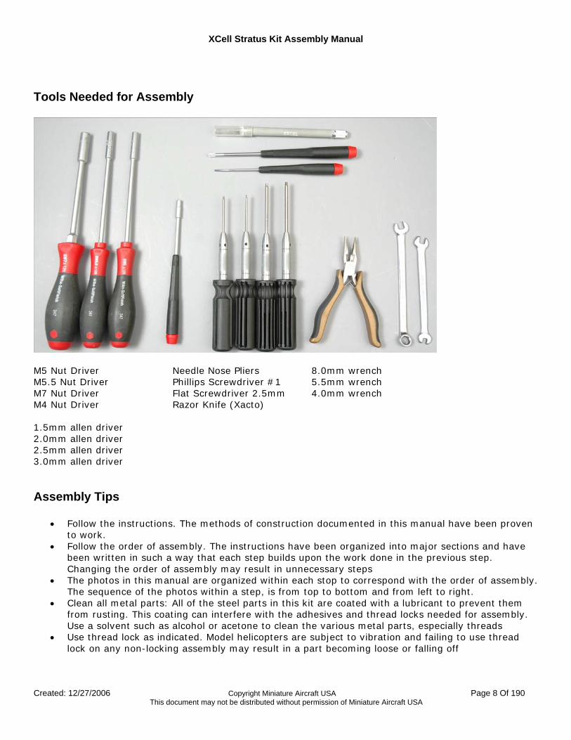
Tools Needed for Assembly
M5 Nut Driver M5.5 Nut Driver M7 Nut Driver M4 Nut Driver 1.5mm allen driver 2.0mm allen driver 2.5mm allen driver 3.0mm allen driver
Needle Nose Pliers Phillips Screwdriver #1 Flat Screwdriver 2.5mm Razor Knife (Xacto)
8.0mm wrench 5.5mm wrench 4.0mm wrench
Assembly Tips
• Follow the instructions. The methods of construction documented in this manual have been proven to work.
• Follow the order of assembly. The instructions have been organized into major sections and have been written in such a way that each step builds upon the work done in the previous step. Changing the order of assembly may result in unnecessary steps
• The photos in this manual are organized within each stop to correspond with the order of assembly. The sequence of the photos within a step, is from top to bottom and from left to right.
• Clean all metal parts: All of the steel parts in this kit are coated with a lubricant to prevent them from rusting. This coating can interfere with the adhesives and thread locks needed for assembly. Use a solvent such as alcohol or acetone to clean the various metal parts, especially threads
• Use thread lock as indicated. Model helicopters are subject to vibration and failing to use thread lock on any non-locking assembly may result in a part becoming loose or falling off
XCell Stratus Kit Assembly Manual
Created: 12/27/2006 Copyright Miniature Aircraft USA Page 9 Of 190 This document may not be distributed without permission of Miniature Aircraft USA
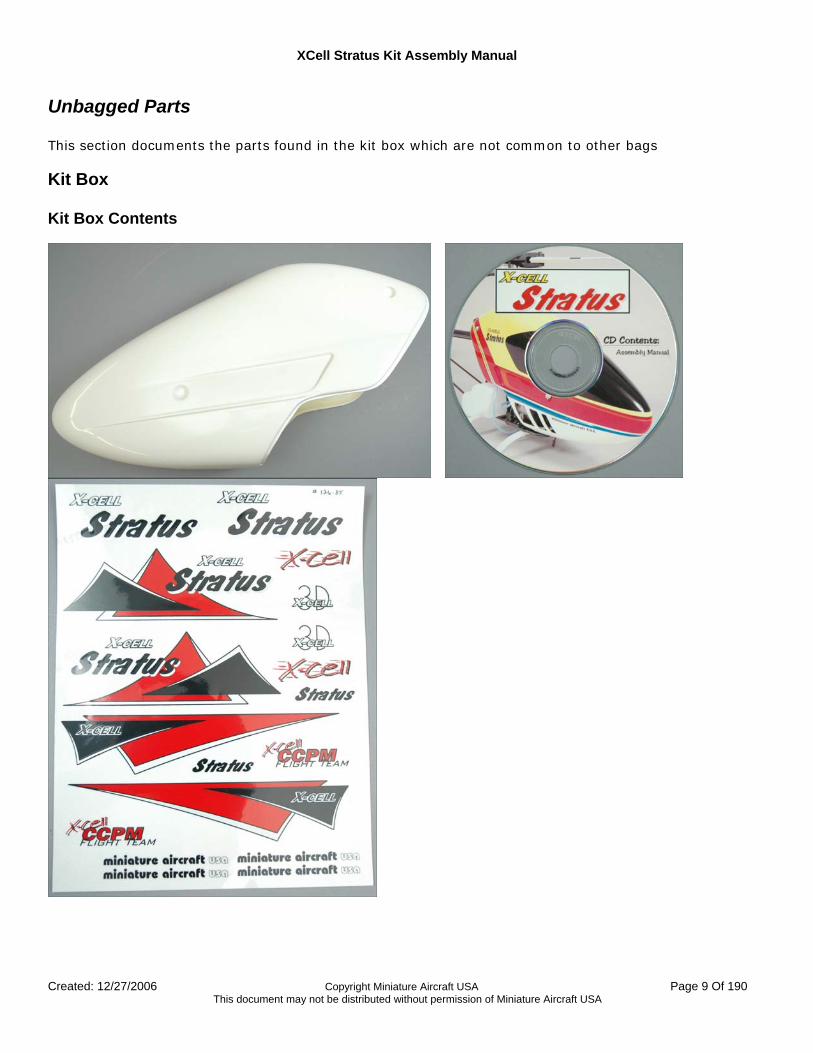
Unbagged Parts This section documents the parts found in the kit box which are not common to other bags
Kit Box Kit Box Contents
XCell Stratus Kit Assembly Manual
Created: 12/27/2006 Copyright Miniature Aircraft USA Page 10 Of 190 This document may not be distributed without permission of Miniature Aircraft USA
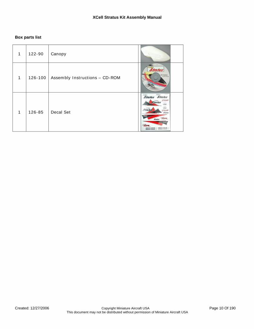
Box parts list
1 122-90 Canopy
1 126-100 Assembly Instructions – CD-ROM
1 126-85 Decal Set
XCell Stratus Kit Assembly Manual
Created: 12/27/2006 Copyright Miniature Aircraft USA Page 11 Of 190 This document may not be distributed without permission of Miniature Aircraft USA
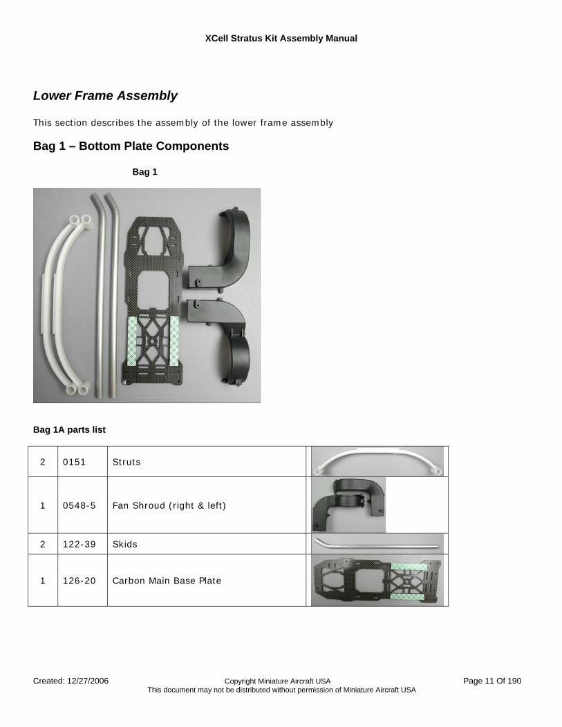
Lower Frame Assembly This section describes the assembly of the lower frame assembly
Bag 1 – Bottom Plate Components
Bag 1
Bag 1A parts list
2 0151 Struts
1 0548-5 Fan Shroud (right & left)
2 122-39 Skids
1 126-20 Carbon Main Base Plate
XCell Stratus Kit Assembly Manual
Created: 12/27/2006 Copyright Miniature Aircraft USA Page 12 Of 190 This document may not be distributed without permission of Miniature Aircraft USA
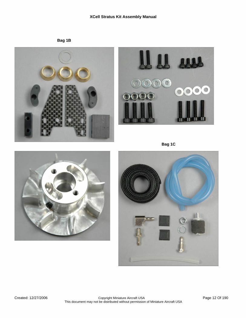
Bag 1B
Bag 1C
XCell Stratus Kit Assembly Manual
Created: 12/27/2006 Copyright Miniature Aircraft USA Page 13 Of 190 This document may not be distributed without permission of Miniature Aircraft USA
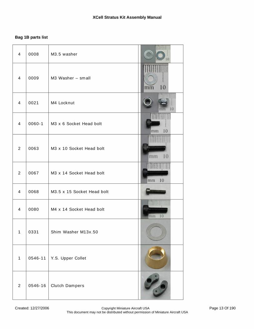
Bag 1B parts list
4 0008 M3.5 washer
4 0009 M3 Washer – small
4 0021 M4 Locknut
4 0060-1 M3 x 6 Socket Head bolt
2 0063 M3 x 10 Socket Head bolt
2 0067 M3 x 14 Socket Head bolt
4 0068 M3.5 x 15 Socket Head bolt
4 0080 M4 x 14 Socket Head bolt
1 0331 Shim Washer M13x.50
1 0546-11 Y.S. Upper Collet
2 0546-16 Clutch Dampers
XCell Stratus Kit Assembly Manual
Created: 12/27/2006 Copyright Miniature Aircraft USA Page 14 Of 190 This document may not be distributed without permission of Miniature Aircraft USA
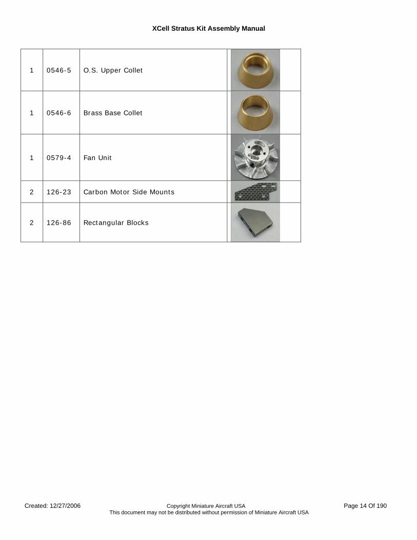
1 0546-5 O.S. Upper Collet
1 0546-6 Brass Base Collet
1 0579-4 Fan Unit
2 126-23 Carbon Motor Side Mounts
2 126-86 Rectangular Blocks
XCell Stratus Kit Assembly Manual
Created: 12/27/2006 Copyright Miniature Aircraft USA Page 15 Of 190 This document may not be distributed without permission of Miniature Aircraft USA
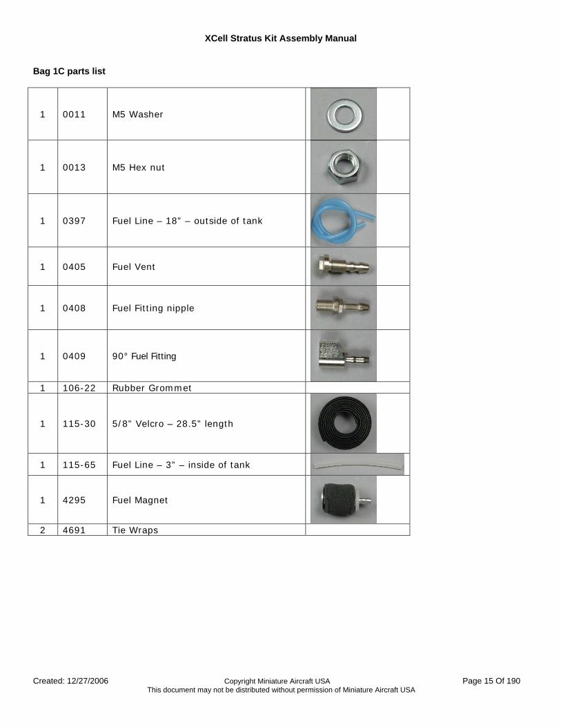
Bag 1C parts list
1 0011 M5 Washer
1 0013 M5 Hex nut
1 0397 Fuel Line – 18” – outside of tank
1 0405 Fuel Vent
1 0408 Fuel Fitting nipple
1 0409 90° Fuel Fitting
1 106-22 Rubber Grommet
1 115-30 5/8” Velcro – 28.5” length
1 115-65 Fuel Line – 3” – inside of tank
1 4295 Fuel Magnet
2 4691 Tie Wraps
XCell Stratus Kit Assembly Manual
Created: 12/27/2006 Copyright Miniature Aircraft USA Page 16 Of 190 This document may not be distributed without permission of Miniature Aircraft USA
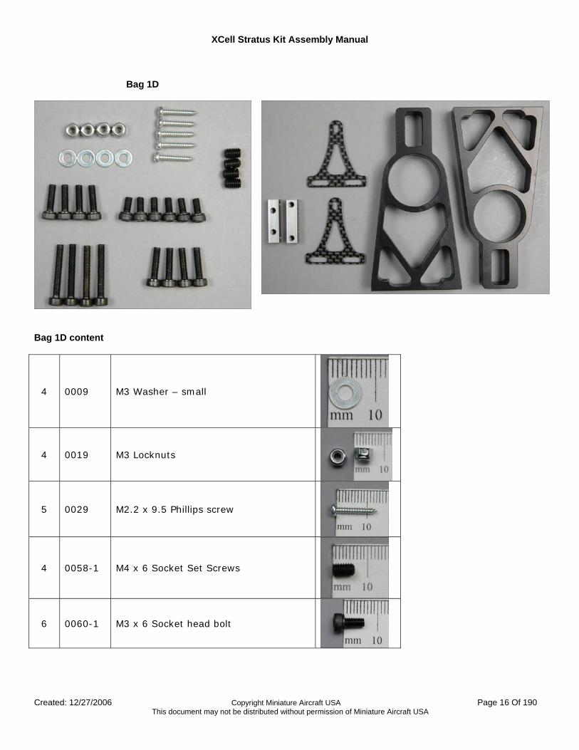
Bag 1D
Bag 1D content
4 0009 M3 Washer – small
4 0019 M3 Locknuts
5 0029 M2.2 x 9.5 Phillips screw
4 0058-1 M4 x 6 Socket Set Screws
6 0060-1 M3 x 6 Socket head bolt
XCell Stratus Kit Assembly Manual
Created: 12/27/2006 Copyright Miniature Aircraft USA Page 17 Of 190 This document may not be distributed without permission of Miniature Aircraft USA
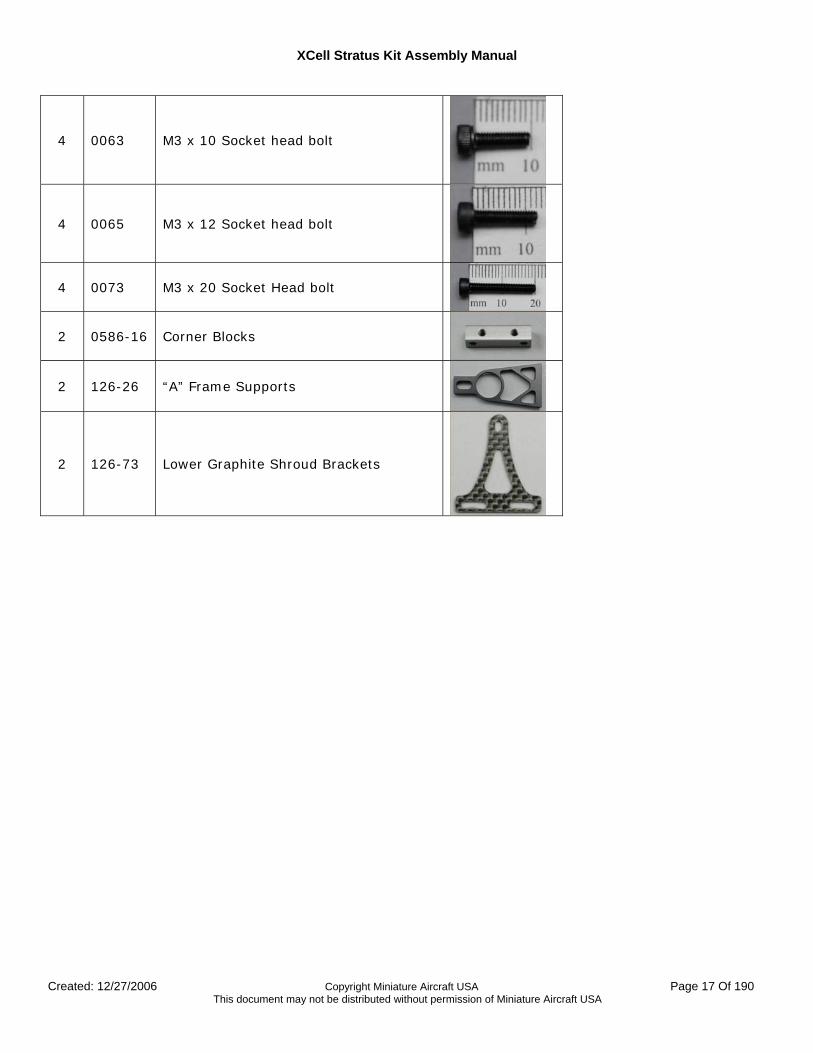
4 0063 M3 x 10 Socket head bolt
4 0065 M3 x 12 Socket head bolt
4 0073 M3 x 20 Socket Head bolt
2 0586-16 Corner Blocks
2 126-26 “A” Frame Supports
2 126-73 Lower Graphite Shroud Brackets
XCell Stratus Kit Assembly Manual
Created: 12/27/2006 Copyright Miniature Aircraft USA Page 18 Of 190 This document may not be distributed without permission of Miniature Aircraft USA
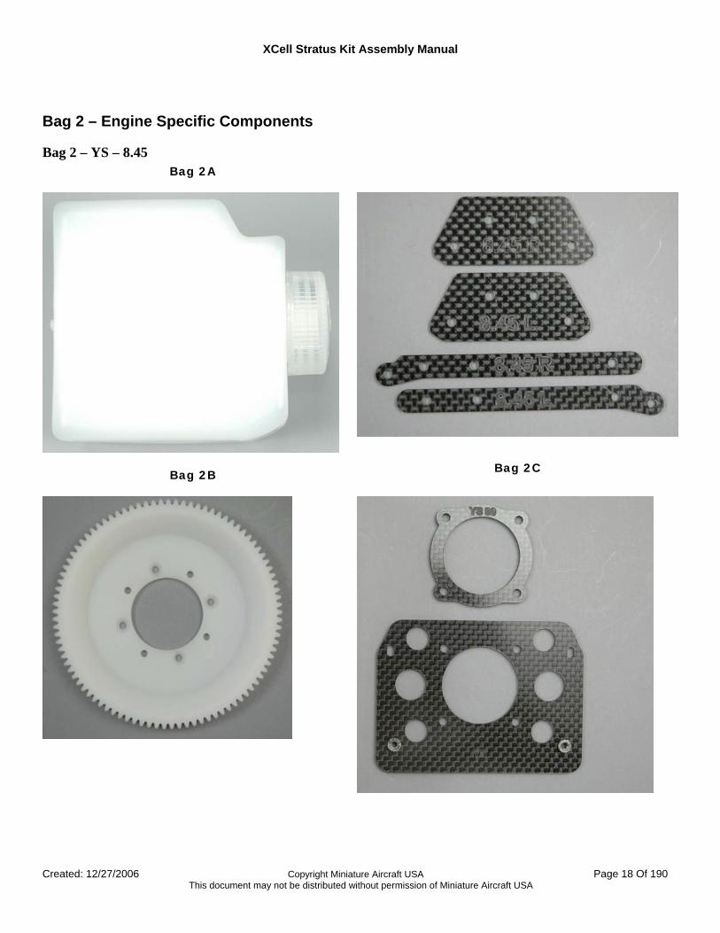
Bag 2 – Engine Specific Components
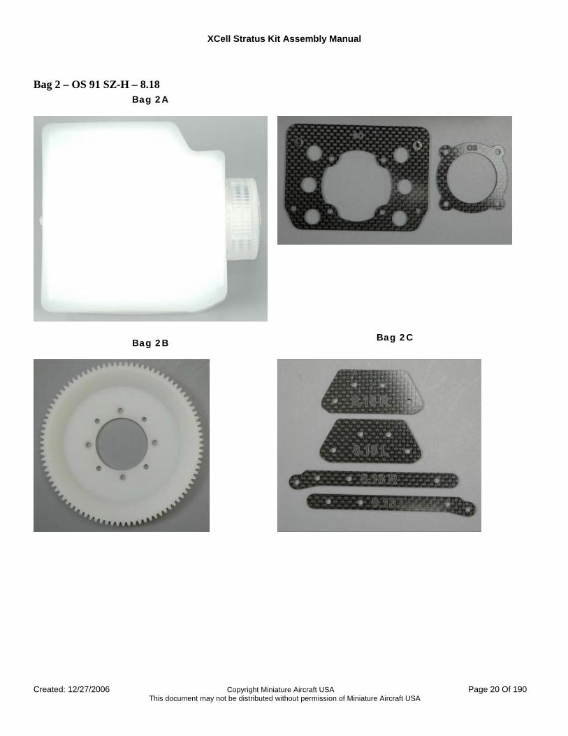
Bag 2 – YS – 8.45 Bag 2A
Bag 2B
Bag 2C
XCell Stratus Kit Assembly Manual
Created: 12/27/2006 Copyright Miniature Aircraft USA Page 19 Of 190 This document may not be distributed without permission of Miniature Aircraft USA
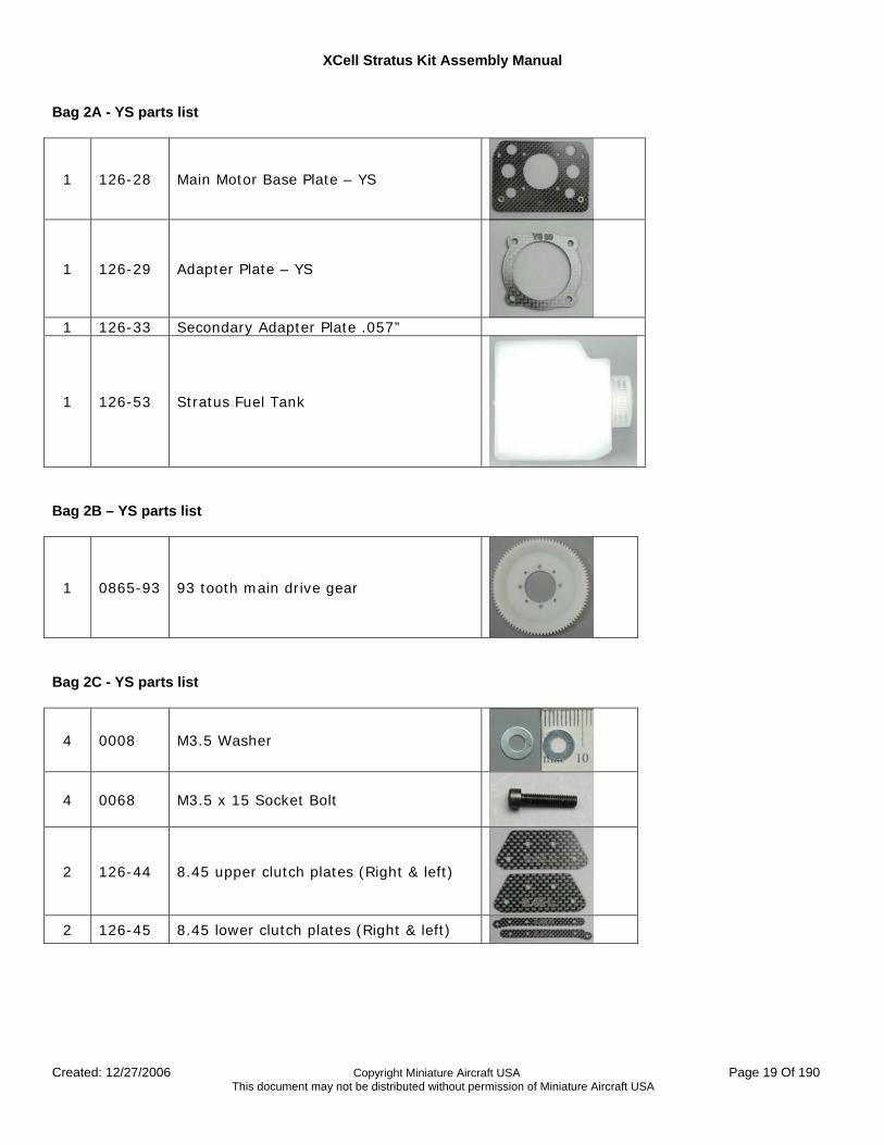
Bag 2A - YS parts list
1 126-28 Main Motor Base Plate – YS
1 126-29 Adapter Plate – YS
1 126-33 Secondary Adapter Plate .057”
1 126-53 Stratus Fuel Tank
Bag 2B – YS parts list
1 0865-93 93 tooth main drive gear
Bag 2C - YS parts list
4 0008 M3.5 Washer
4 0068 M3.5 x 15 Socket Bolt
2 126-44 8.45 upper clutch plates (Right & left)
2 126-45 8.45 lower clutch plates (Right & left)
XCell Stratus Kit Assembly Manual
Created: 12/27/2006 Copyright Miniature Aircraft USA Page 20 Of 190 This document may not be distributed without permission of Miniature Aircraft USA
Bag 2 – OS 91 SZ-H – 8.18 Bag 2A
Bag 2B
Bag 2C
XCell Stratus Kit Assembly Manual
Created: 12/27/2006 Copyright Miniature Aircraft USA Page 21 Of 190 This document may not be distributed without permission of Miniature Aircraft USA
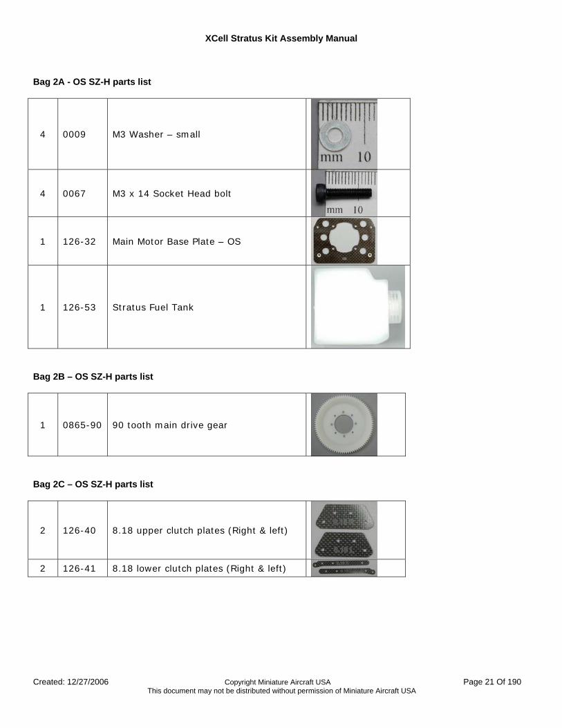
Bag 2A - OS SZ-H parts list
4 0009 M3 Washer – small
4 0067 M3 x 14 Socket Head bolt
1 126-32 Main Motor Base Plate – OS
1 126-53 Stratus Fuel Tank
Bag 2B – OS SZ-H parts list
1 0865-90 90 tooth main drive gear
Bag 2C – OS SZ-H parts list
2 126-40 8.18 upper clutch plates (Right & left)
2 126-41 8.18 lower clutch plates (Right & left)
XCell Stratus Kit Assembly Manual
Created: 12/27/2006 Copyright Miniature Aircraft USA Page 22 Of 190 This document may not be distributed without permission of Miniature Aircraft USA
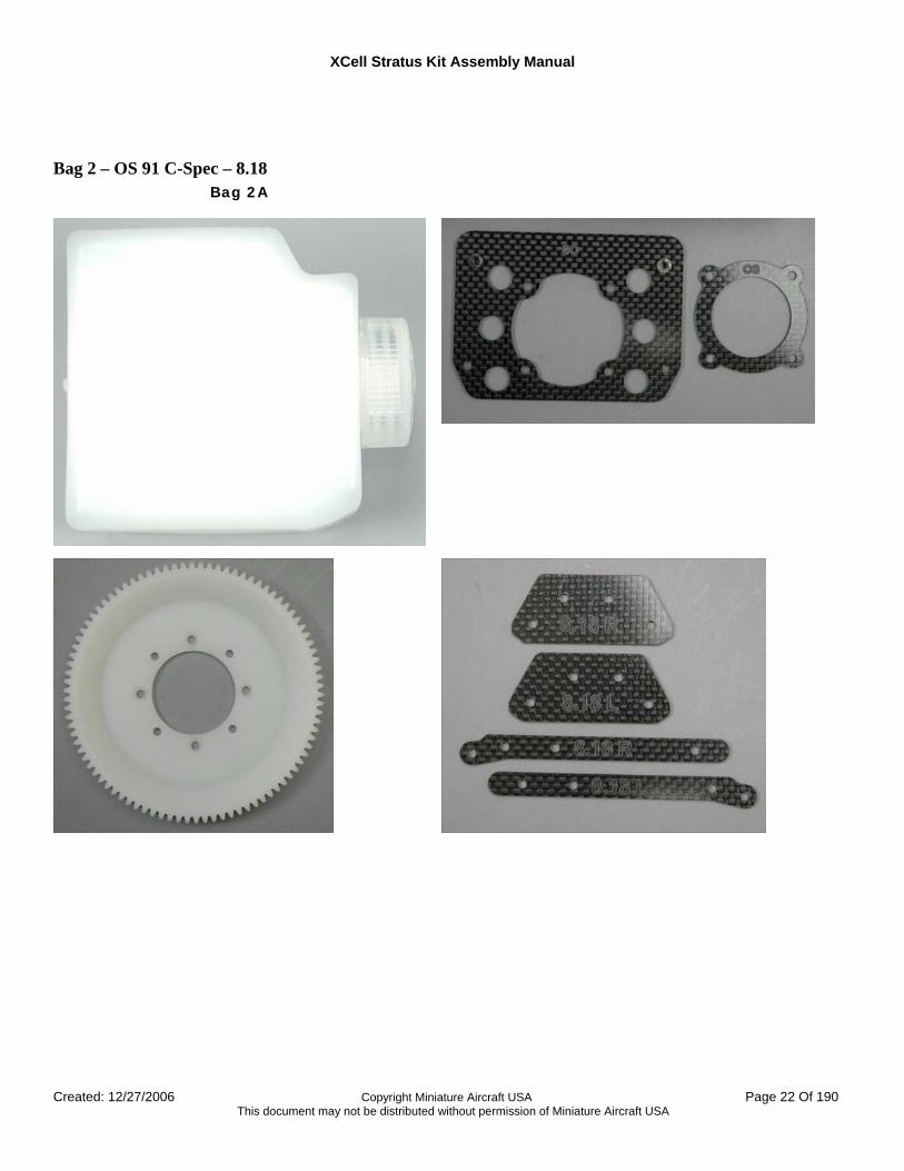
Bag 2 – OS 91 C-Spec – 8.18 Bag 2A

XCell Stratus Kit Assembly Manual
Created: 12/27/2006 Copyright Miniature Aircraft USA Page 23 Of 190 This document may not be distributed without permission of Miniature Aircraft USA
Bag 2A - OS C-Spec parts list
4 0008 M3.5 Washer
4 0068 M3.5 x 15 Socket Bolt
1 0865-90 90 tooth main drive gear
1 126-24 Main Motor Base Plate – OS
1 126-25 Adapter Plate – OS
2 126-40 8.18 upper clutch plates (Right & left)
2 126-41 8.18 lower clutch plates (Right & left)
1 126-53 Stratus Fuel Tank
XCell Stratus Kit Assembly Manual
Created: 12/27/2006 Copyright Miniature Aircraft USA Page 24 Of 190 This document may not be distributed without permission of Miniature Aircraft USA
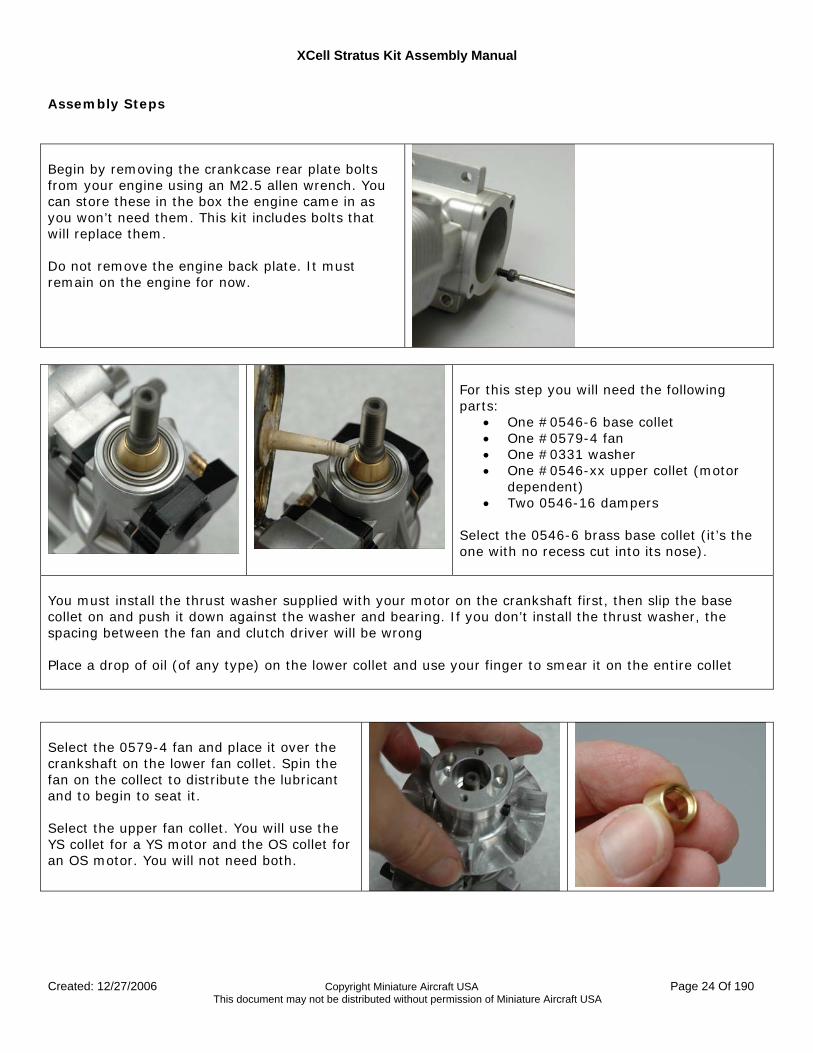
Assembly Steps Begin by removing the crankcase rear plate bolts from your engine using an M2.5 allen wrench. You can store these in the box the engine came in as you won’t need them. This kit includes bolts that will replace them. Do not remove the engine back plate. It must remain on the engine for now.
For this step you will need the following parts:
• One #0546-6 base collet • One #0579-4 fan • One #0331 washer • One #0546-xx upper collet (motor
dependent) • Two 0546-16 dampers
Select the 0546-6 brass base collet (it’s the one with no recess cut into its nose).
You must install the thrust washer supplied with your motor on the crankshaft first, then slip the base collet on and push it down against the washer and bearing. If you don’t install the thrust washer, the spacing between the fan and clutch driver will be wrong Place a drop of oil (of any type) on the lower collet and use your finger to smear it on the entire collet Select the 0579-4 fan and place it over the crankshaft on the lower fan collet. Spin the fan on the collect to distribute the lubricant and to begin to seat it. Select the upper fan collet. You will use the YS collet for a YS motor and the OS collet for an OS motor. You will not need both.
XCell Stratus Kit Assembly Manual
Created: 12/27/2006 Copyright Miniature Aircraft USA Page 25 Of 190 This document may not be distributed without permission of Miniature Aircraft USA
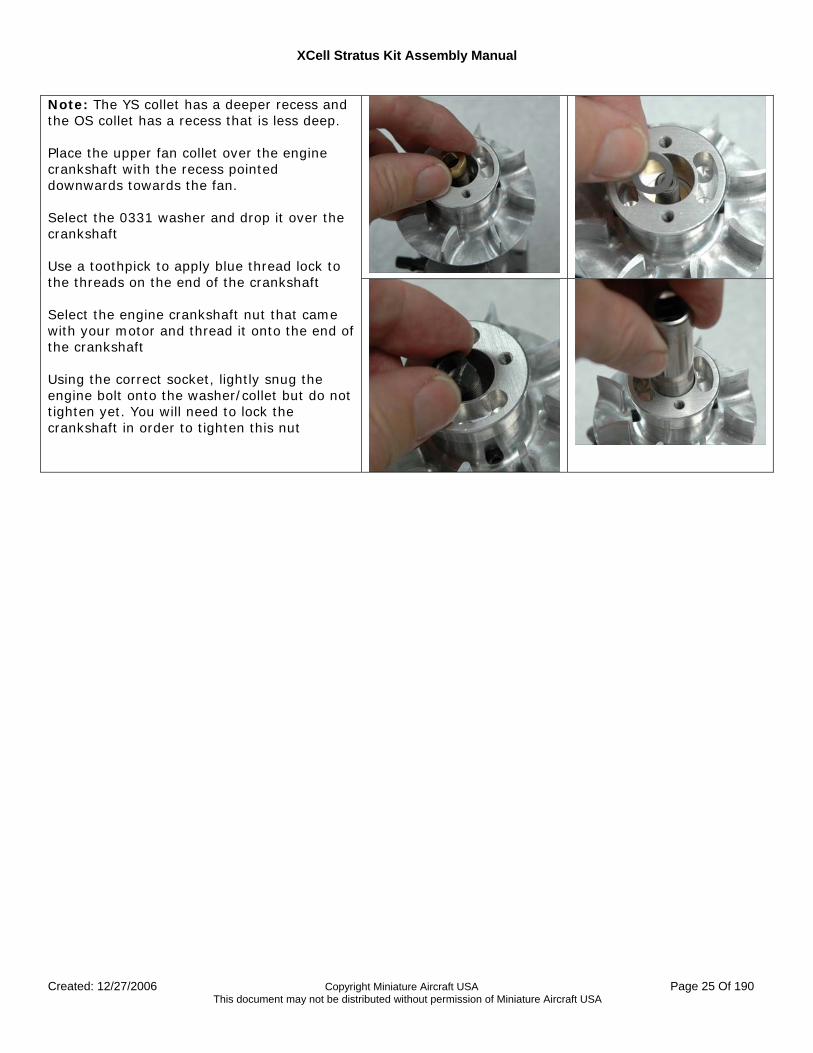
Note: The YS collet has a deeper recess and the OS collet has a recess that is less deep. Place the upper fan collet over the engine crankshaft with the recess pointed downwards towards the fan. Select the 0331 washer and drop it over the crankshaft Use a toothpick to apply blue thread lock to the threads on the end of the crankshaft Select the engine crankshaft nut that came with your motor and thread it onto the end of the crankshaft Using the correct socket, lightly snug the engine bolt onto the washer/collet but do not tighten yet. You will need to lock the crankshaft in order to tighten this nut
XCell Stratus Kit Assembly Manual
Created: 12/27/2006 Copyright Miniature Aircraft USA Page 26 Of 190 This document may not be distributed without permission of Miniature Aircraft USA
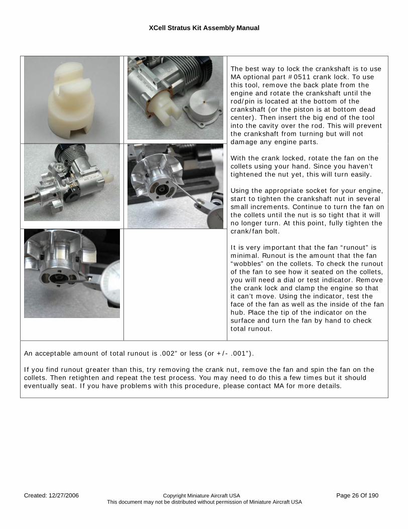
The best way to lock the crankshaft is to use MA optional part #0511 crank lock. To use this tool, remove the back plate from the engine and rotate the crankshaft until the rod/pin is located at the bottom of the crankshaft (or the piston is at bottom dead center). Then insert the big end of the tool into the cavity over the rod. This will prevent the crankshaft from turning but will not damage any engine parts. With the crank locked, rotate the fan on the collets using your hand. Since you haven’t tightened the nut yet, this will turn easily. Using the appropriate socket for your engine, start to tighten the crankshaft nut in several small increments. Continue to turn the fan on the collets until the nut is so tight that it will no longer turn. At this point, fully tighten the crank/fan bolt. It is very important that the fan “runout” is minimal. Runout is the amount that the fan “wobbles” on the collets. To check the runout of the fan to see how it seated on the collets, you will need a dial or test indicator. Remove the crank lock and clamp the engine so that it can’t move. Using the indicator, test the face of the fan as well as the inside of the fan hub. Place the tip of the indicator on the surface and turn the fan by hand to check total runout.
An acceptable amount of total runout is .002” or less (or +/- .001”). If you find runout greater than this, try removing the crank nut, remove the fan and spin the fan on the collets. Then retighten and repeat the test process. You may need to do this a few times but it should eventually seat. If you have problems with this procedure, please contact MA for more details.
XCell Stratus Kit Assembly Manual
Created: 12/27/2006 Copyright Miniature Aircraft USA Page 27 Of 190 This document may not be distributed without permission of Miniature Aircraft USA
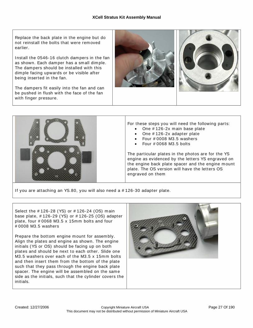
Replace the back plate in the engine but do not reinstall the bolts that were removed earlier. Install the 0546-16 clutch dampers in the fan as shown. Each damper has a small dimple. The dampers should be installed with this dimple facing upwards or be visible after being inserted in the fan. The dampers fit easily into the fan and can be pushed in flush with the face of the fan with finger pressure.
For these steps you will need the following parts:
• One #126-2x main base plate • One #126-2x adapter plate • Four #0008 M3.5 washers • Four #0068 M3.5 bolts
The particular plates in the photos are for the YS engine as evidenced by the letters YS engraved on the engine back plate spacer and the engine mount plate. The OS version will have the letters OS engraved on them
If you are attaching an YS.80, you will also need a #126-30 adapter plate. Select the #126-28 (YS) or #126-24 (OS) main base plate, #126-29 (YS) or #126-25 (OS) adapter plate, four #0068 M3.5 x 15mm bolts and four #0008 M3.5 washers Prepare the bottom engine mount for assembly. Align the plates and engine as shown. The engine initials (YS or OS) should be facing up on both plates and should be next to each other. Slide one M3.5 washers over each of the M3.5 x 15mm bolts and then insert them from the bottom of the plate such that they pass through the engine back plate spacer. The engine will be assembled on the same side as the initials, such that the cylinder covers the initials.
XCell Stratus Kit Assembly Manual
Created: 12/27/2006 Copyright Miniature Aircraft USA Page 28 Of 190 This document may not be distributed without permission of Miniature Aircraft USA
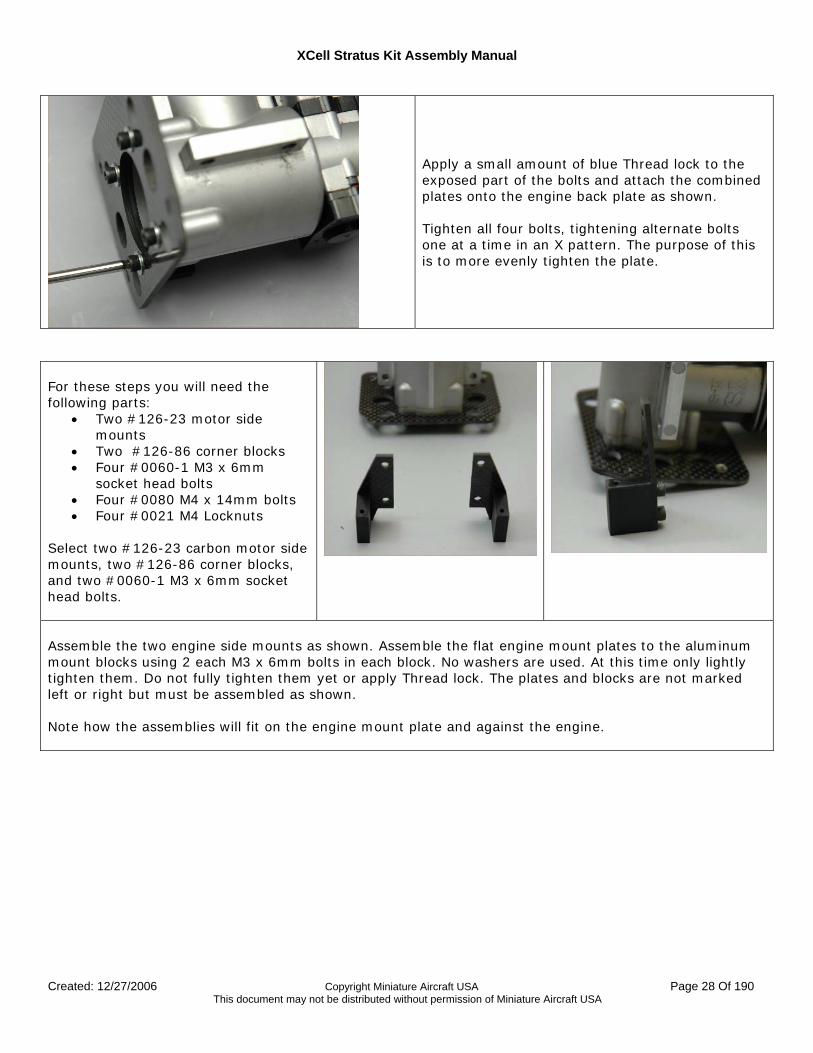
Apply a small amount of blue Thread lock to the exposed part of the bolts and attach the combined plates onto the engine back plate as shown. Tighten all four bolts, tightening alternate bolts one at a time in an X pattern. The purpose of this is to more evenly tighten the plate.
For these steps you will need the following parts:
• Two #126-23 motor side mounts
• Two #126-86 corner blocks • Four #0060-1 M3 x 6mm
socket head bolts • Four #0080 M4 x 14mm bolts • Four #0021 M4 Locknuts
Select two #126-23 carbon motor side mounts, two #126-86 corner blocks, and two #0060-1 M3 x 6mm socket head bolts.
Assemble the two engine side mounts as shown. Assemble the flat engine mount plates to the aluminum mount blocks using 2 each M3 x 6mm bolts in each block. No washers are used. At this time only lightly tighten them. Do not fully tighten them yet or apply Thread lock. The plates and blocks are not marked left or right but must be assembled as shown. Note how the assemblies will fit on the engine mount plate and against the engine.
XCell Stratus Kit Assembly Manual
Created: 12/27/2006 Copyright Miniature Aircraft USA Page 29 Of 190 This document may not be distributed without permission of Miniature Aircraft USA
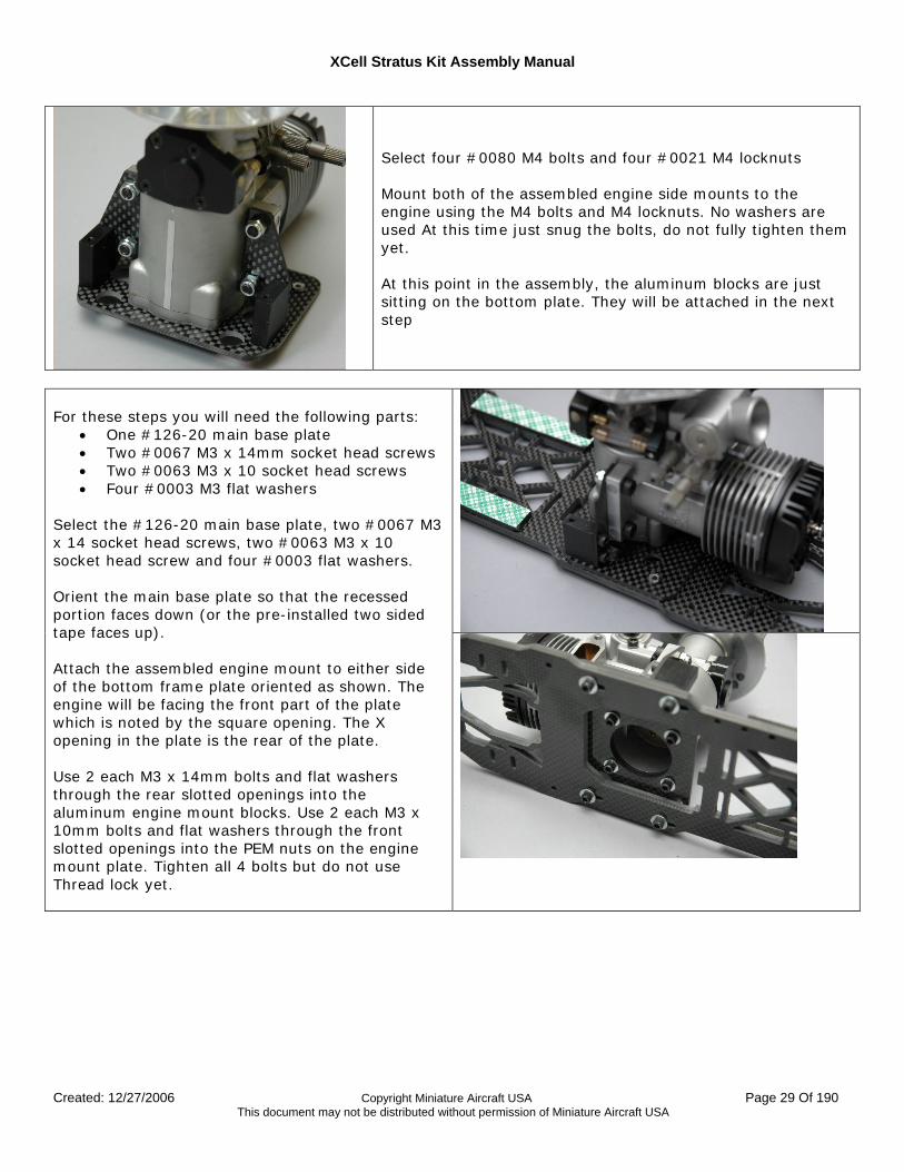
Select four #0080 M4 bolts and four #0021 M4 locknuts Mount both of the assembled engine side mounts to the engine using the M4 bolts and M4 locknuts. No washers are used At this time just snug the bolts, do not fully tighten them yet. At this point in the assembly, the aluminum blocks are just sitting on the bottom plate. They will be attached in the next step
For these steps you will need the following parts:
• One #126-20 main base plate • Two #0067 M3 x 14mm socket head screws • Two #0063 M3 x 10 socket head screws • Four #0003 M3 flat washers
Select the #126-20 main base plate, two #0067 M3 x 14 socket head screws, two #0063 M3 x 10 socket head screw and four #0003 flat washers. Orient the main base plate so that the recessed portion faces down (or the pre-installed two sided tape faces up). Attach the assembled engine mount to either side of the bottom frame plate oriented as shown. The engine will be facing the front part of the plate which is noted by the square opening. The X opening in the plate is the rear of the plate. Use 2 each M3 x 14mm bolts and flat washers through the rear slotted openings into the aluminum engine mount blocks. Use 2 each M3 x 10mm bolts and flat washers through the front slotted openings into the PEM nuts on the engine mount plate. Tighten all 4 bolts but do not use Thread lock yet.
XCell Stratus Kit Assembly Manual
Created: 12/27/2006 Copyright Miniature Aircraft USA Page 30 Of 190 This document may not be distributed without permission of Miniature Aircraft USA
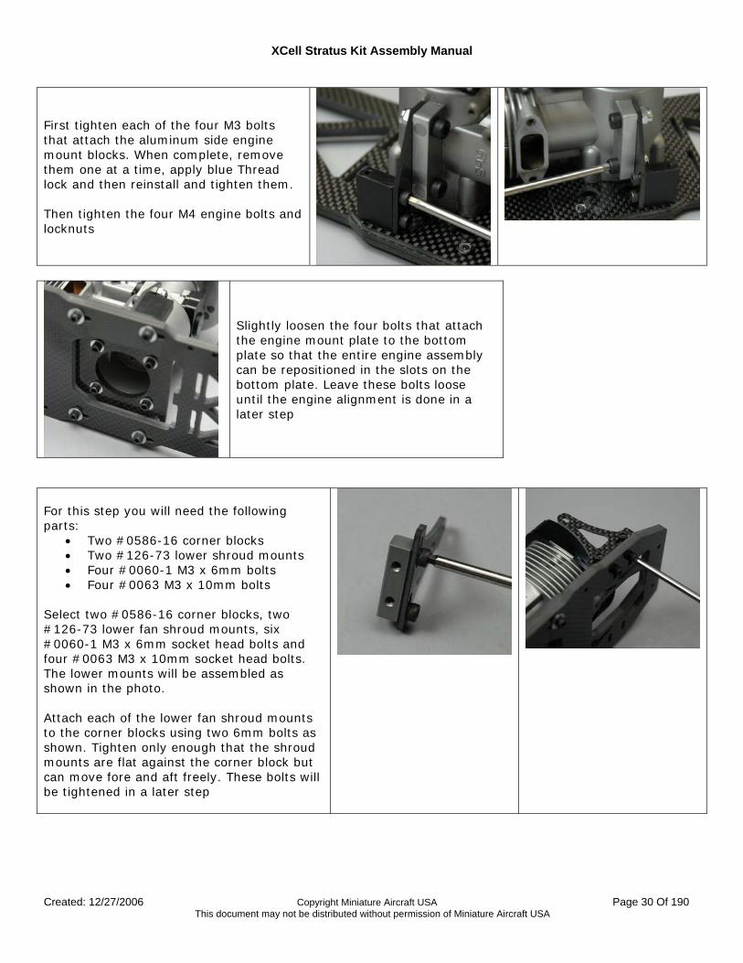
First tighten each of the four M3 bolts that attach the aluminum side engine mount blocks. When complete, remove them one at a time, apply blue Thread lock and then reinstall and tighten them. Then tighten the four M4 engine bolts and locknuts
Slightly loosen the four bolts that attach the engine mount plate to the bottom plate so that the entire engine assembly can be repositioned in the slots on the bottom plate. Leave these bolts loose until the engine alignment is done in a later step
For this step you will need the following parts:
• Two #0586-16 corner blocks • Two #126-73 lower shroud mounts • Four #0060-1 M3 x 6mm bolts • Four #0063 M3 x 10mm bolts
Select two #0586-16 corner blocks, two #126-73 lower fan shroud mounts, six #0060-1 M3 x 6mm socket head bolts and four #0063 M3 x 10mm socket head bolts. The lower mounts will be assembled as shown in the photo. Attach each of the lower fan shroud mounts to the corner blocks using two 6mm bolts as shown. Tighten only enough that the shroud mounts are flat against the corner block but can move fore and aft freely. These bolts will be tightened in a later step
XCell Stratus Kit Assembly Manual
Created: 12/27/2006 Copyright Miniature Aircraft USA Page 31 Of 190 This document may not be distributed without permission of Miniature Aircraft USA
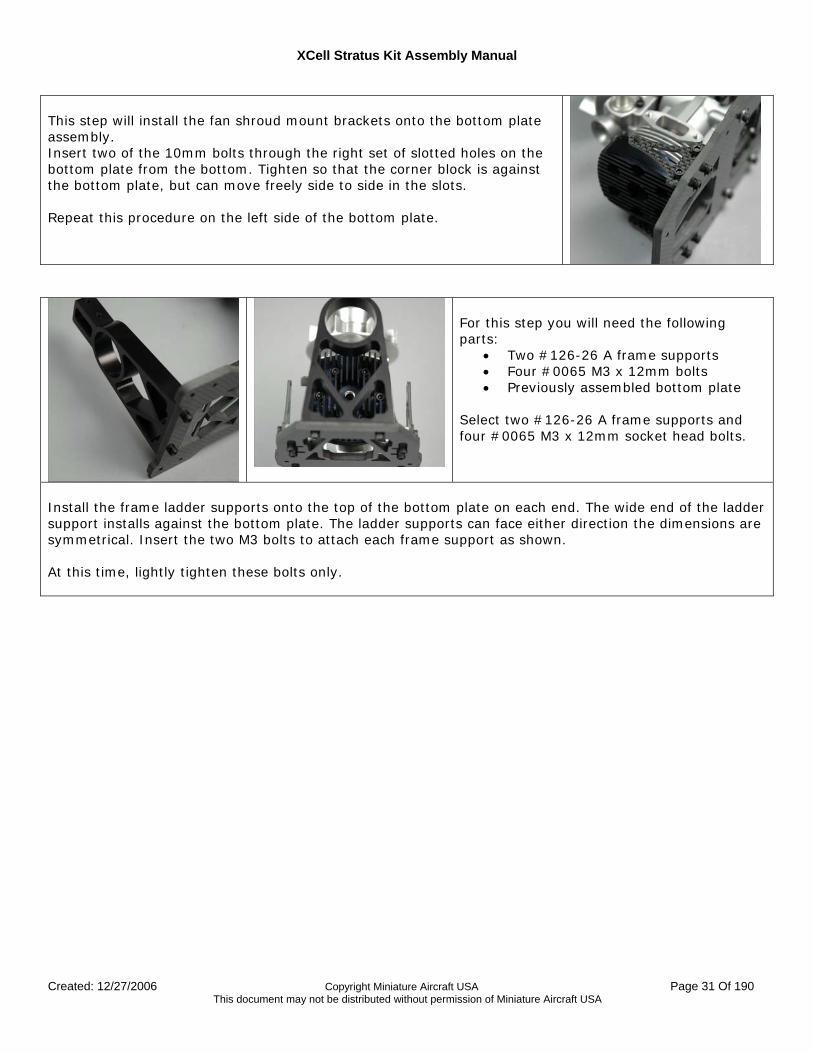
This step will install the fan shroud mount brackets onto the bottom plate assembly. Insert two of the 10mm bolts through the right set of slotted holes on the bottom plate from the bottom. Tighten so that the corner block is against the bottom plate, but can move freely side to side in the slots. Repeat this procedure on the left side of the bottom plate.
For this step you will need the following parts:
• Two #126-26 A frame supports • Four #0065 M3 x 12mm bolts • Previously assembled bottom plate
Select two #126-26 A frame supports and four #0065 M3 x 12mm socket head bolts.
Install the frame ladder supports onto the top of the bottom plate on each end. The wide end of the ladder support installs against the bottom plate. The ladder supports can face either direction the dimensions are symmetrical. Insert the two M3 bolts to attach each frame support as shown. At this time, lightly tighten these bolts only.
XCell Stratus Kit Assembly Manual
Created: 12/27/2006 Copyright Miniature Aircraft USA Page 32 Of 190 This document may not be distributed without permission of Miniature Aircraft USA
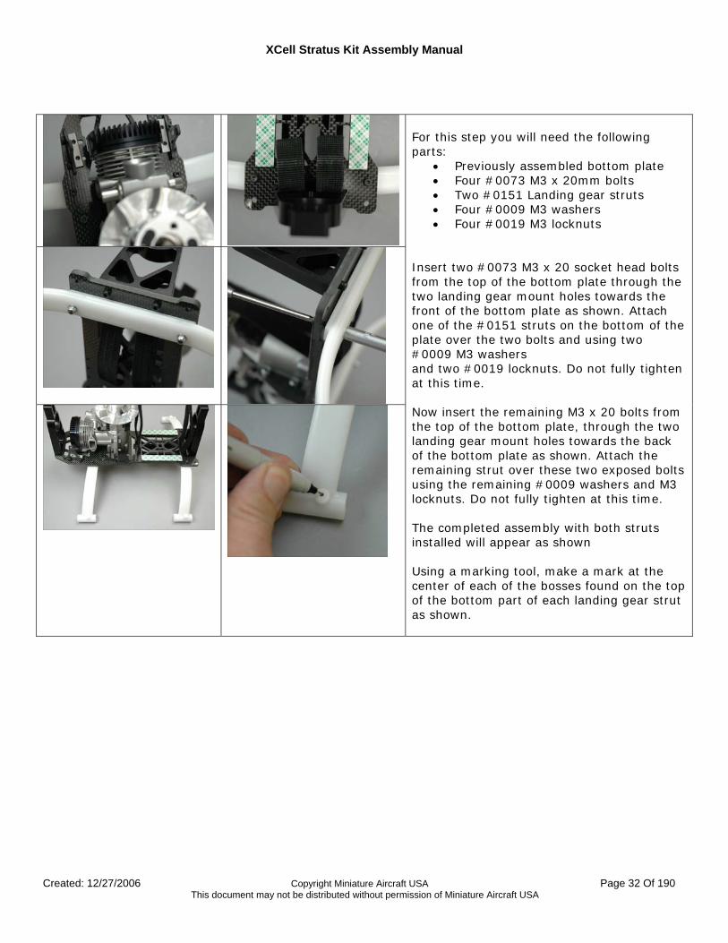
For this step you will need the following parts:
• Previously assembled bottom plate • Four #0073 M3 x 20mm bolts • Two #0151 Landing gear struts • Four #0009 M3 washers • Four #0019 M3 locknuts
Insert two #0073 M3 x 20 socket head bolts from the top of the bottom plate through the two landing gear mount holes towards the front of the bottom plate as shown. Attach one of the #0151 struts on the bottom of the plate over the two bolts and using two #0009 M3 washers and two #0019 locknuts. Do not fully tighten at this time. Now insert the remaining M3 x 20 bolts from the top of the bottom plate, through the two landing gear mount holes towards the back of the bottom plate as shown. Attach the remaining strut over these two exposed bolts using the remaining #0009 washers and M3 locknuts. Do not fully tighten at this time. The completed assembly with both struts installed will appear as shown Using a marking tool, make a mark at the center of each of the bosses found on the top of the bottom part of each landing gear strut as shown.
XCell Stratus Kit Assembly Manual
Created: 12/27/2006 Copyright Miniature Aircraft USA Page 33 Of 190 This document may not be distributed without permission of Miniature Aircraft USA
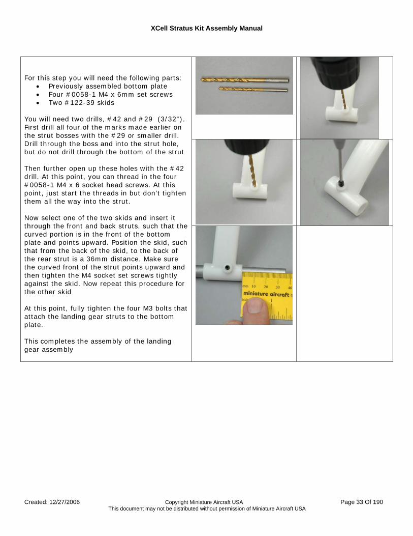
For this step you will need the following parts:
• Previously assembled bottom plate • Four #0058-1 M4 x 6mm set screws • Two #122-39 skids
You will need two drills, #42 and #29 (3/32”). First drill all four of the marks made earlier on the strut bosses with the #29 or smaller drill. Drill through the boss and into the strut hole, but do not drill through the bottom of the strut Then further open up these holes with the #42 drill. At this point, you can thread in the four #0058-1 M4 x 6 socket head screws. At this point, just start the threads in but don’t tighten them all the way into the strut. Now select one of the two skids and insert it through the front and back struts, such that the curved portion is in the front of the bottom plate and points upward. Position the skid, such that from the back of the skid, to the back of the rear strut is a 36mm distance. Make sure the curved front of the strut points upward and then tighten the M4 socket set screws tightly against the skid. Now repeat this procedure for the other skid At this point, fully tighten the four M3 bolts that attach the landing gear struts to the bottom plate. This completes the assembly of the landing gear assembly
XCell Stratus Kit Assembly Manual
Created: 12/27/2006 Copyright Miniature Aircraft USA Page 34 Of 190 This document may not be distributed without permission of Miniature Aircraft USA
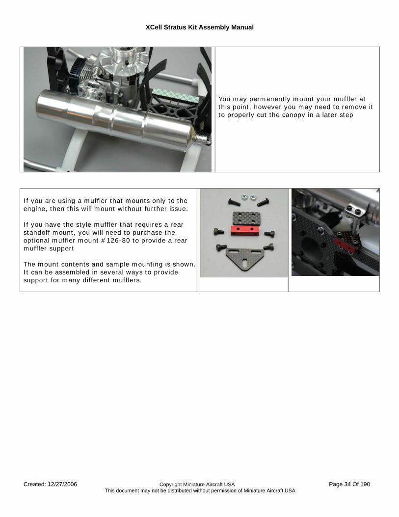
You may permanently mount your muffler at this point, however you may need to remove it to properly cut the canopy in a later step
If you are using a muffler that mounts only to the engine, then this will mount without further issue. If you have the style muffler that requires a rear standoff mount, you will need to purchase the optional muffler mount #126-80 to provide a rear muffler support The mount contents and sample mounting is shown. It can be assembled in several ways to provide support for many different mufflers.
XCell Stratus Kit Assembly Manual
Created: 12/27/2006 Copyright Miniature Aircraft USA Page 35 Of 190 This document may not be distributed without permission of Miniature Aircraft USA
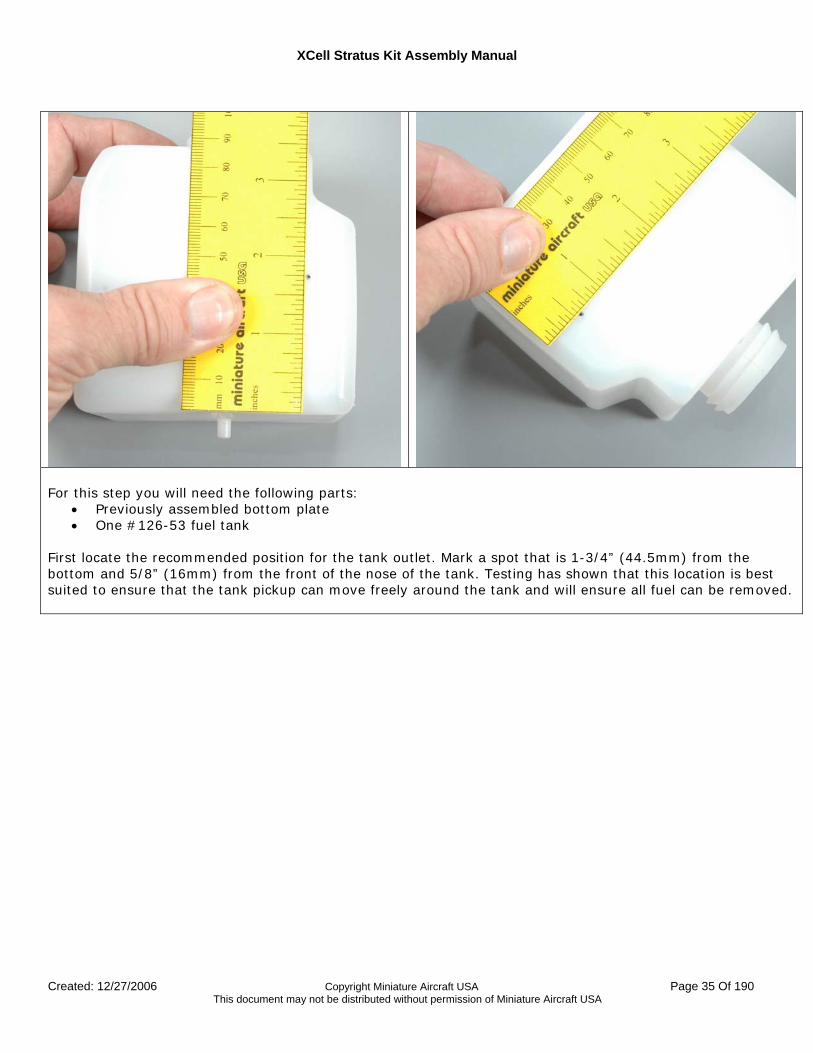
For this step you will need the following parts:
• Previously assembled bottom plate • One #126-53 fuel tank
First locate the recommended position for the tank outlet. Mark a spot that is 1-3/4” (44.5mm) from the bottom and 5/8” (16mm) from the front of the nose of the tank. Testing has shown that this location is best suited to ensure that the tank pickup can move freely around the tank and will ensure all fuel can be removed.
XCell Stratus Kit Assembly Manual
Created: 12/27/2006 Copyright Miniature Aircraft USA Page 36 Of 190 This document may not be distributed without permission of Miniature Aircraft USA
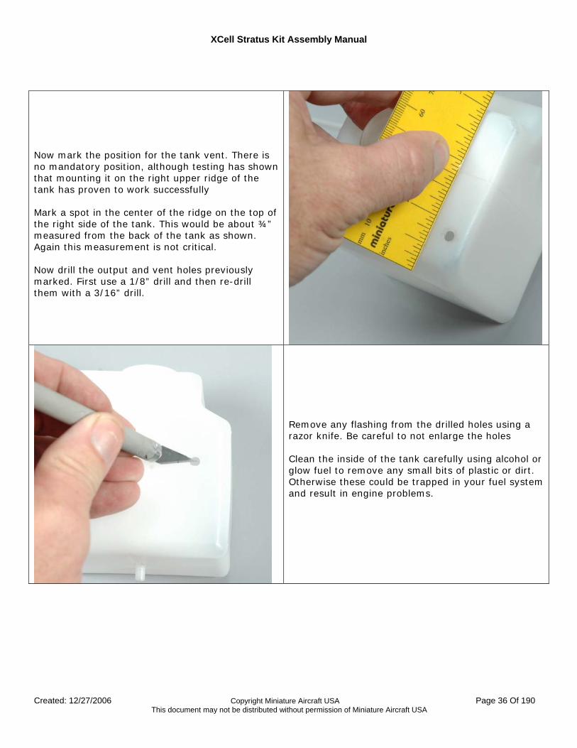
Now mark the position for the tank vent. There is no mandatory position, although testing has shown that mounting it on the right upper ridge of the tank has proven to work successfully Mark a spot in the center of the ridge on the top of the right side of the tank. This would be about ¾” measured from the back of the tank as shown. Again this measurement is not critical. Now drill the output and vent holes previously marked. First use a 1/8” drill and then re-drill them with a 3/16” drill.
Remove any flashing from the drilled holes using a razor knife. Be careful to not enlarge the holes Clean the inside of the tank carefully using alcohol or glow fuel to remove any small bits of plastic or dirt. Otherwise these could be trapped in your fuel system and result in engine problems.
XCell Stratus Kit Assembly Manual
Created: 12/27/2006 Copyright Miniature Aircraft USA Page 37 Of 190 This document may not be distributed without permission of Miniature Aircraft USA
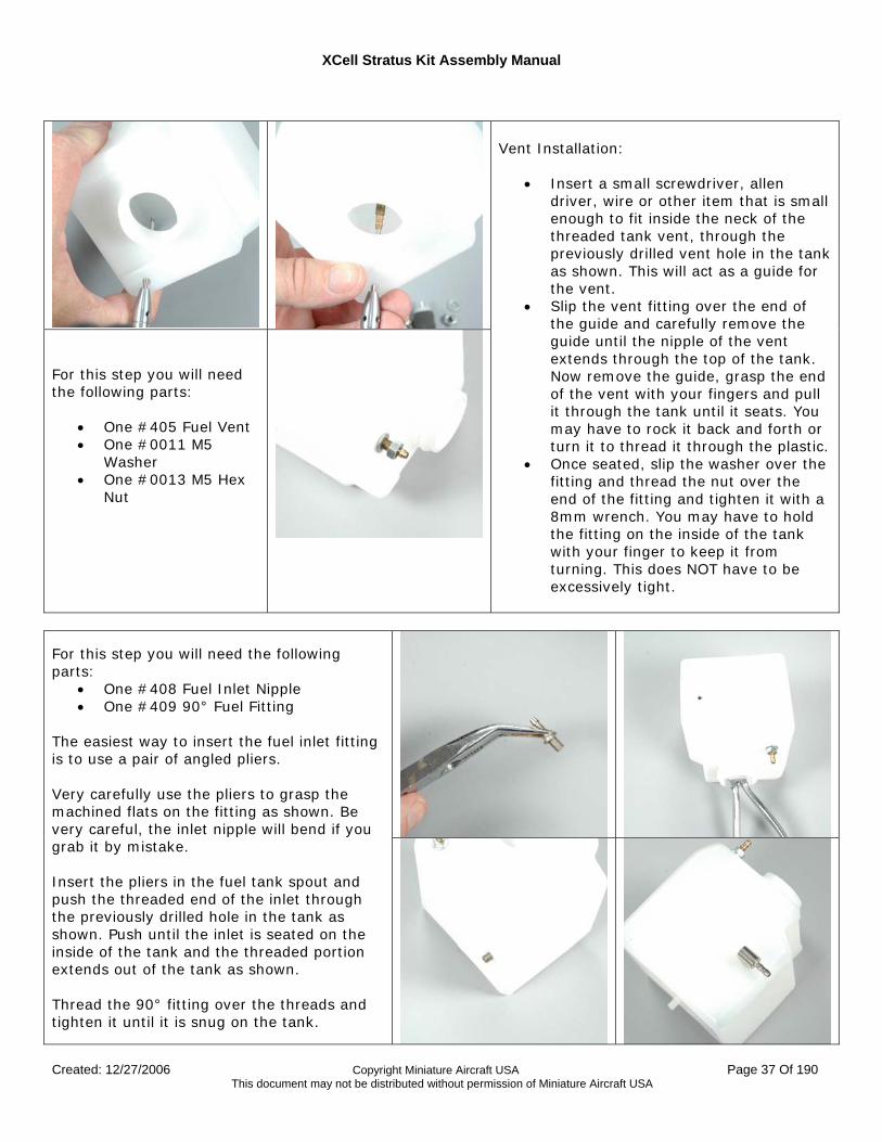
For this step you will need the following parts:
• One #405 Fuel Vent • One #0011 M5
Washer • One #0013 M5 Hex
Nut
Vent Installation:
• Insert a small screwdriver, allen driver, wire or other item that is small enough to fit inside the neck of the threaded tank vent, through the previously drilled vent hole in the tank as shown. This will act as a guide for the vent.
• Slip the vent fitting over the end of the guide and carefully remove the guide until the nipple of the vent extends through the top of the tank. Now remove the guide, grasp the end of the vent with your fingers and pull it through the tank until it seats. You may have to rock it back and forth or turn it to thread it through the plastic.
• Once seated, slip the washer over the fitting and thread the nut over the end of the fitting and tighten it with a 8mm wrench. You may have to hold the fitting on the inside of the tank with your finger to keep it from turning. This does NOT have to be excessively tight.
For this step you will need the following parts:
• One #408 Fuel Inlet Nipple • One #409 90° Fuel Fitting
The easiest way to insert the fuel inlet fitting is to use a pair of angled pliers. Very carefully use the pliers to grasp the machined flats on the fitting as shown. Be very careful, the inlet nipple will bend if you grab it by mistake. Insert the pliers in the fuel tank spout and push the threaded end of the inlet through the previously drilled hole in the tank as shown. Push until the inlet is seated on the inside of the tank and the threaded portion extends out of the tank as shown. Thread the 90° fitting over the threads and tighten it until it is snug on the tank.
XCell Stratus Kit Assembly Manual
Created: 12/27/2006 Copyright Miniature Aircraft USA Page 38 Of 190 This document may not be distributed without permission of Miniature Aircraft USA
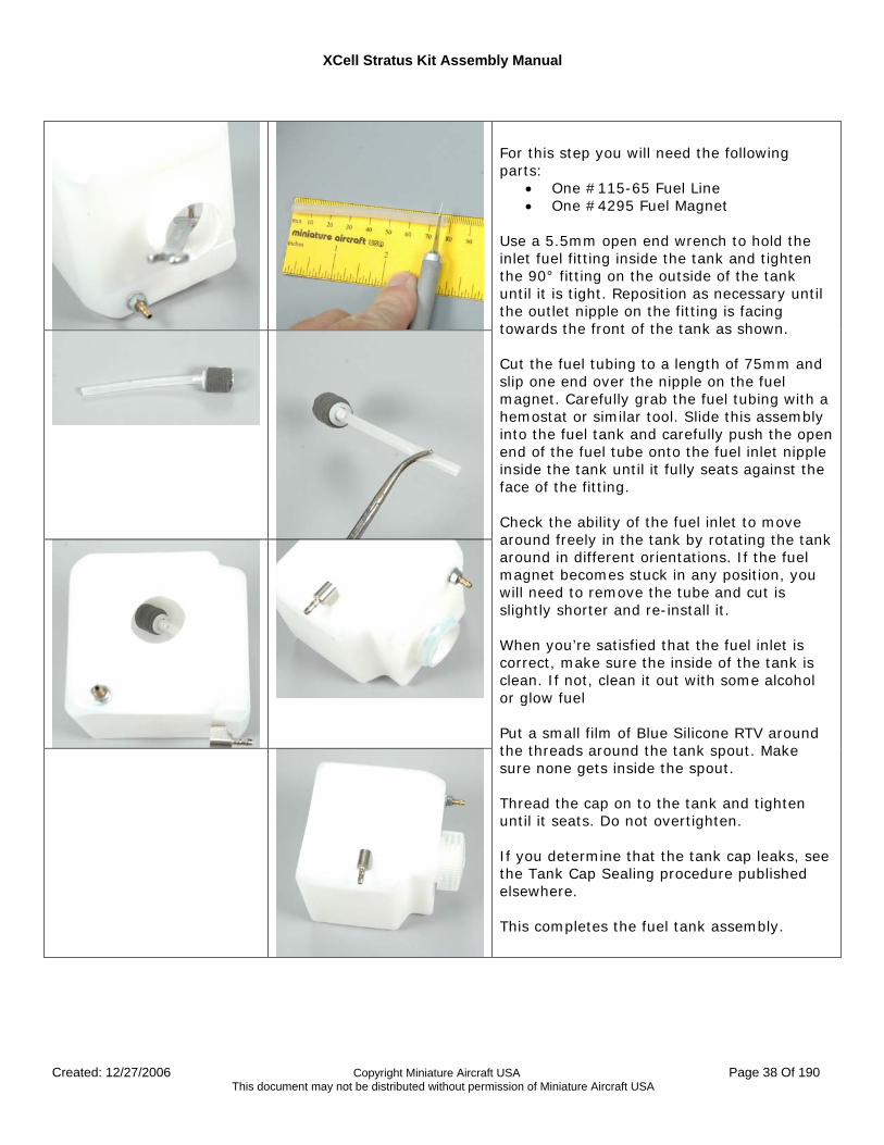
For this step you will need the following parts:
• One #115-65 Fuel Line • One #4295 Fuel Magnet
Use a 5.5mm open end wrench to hold the inlet fuel fitting inside the tank and tighten the 90° fitting on the outside of the tank until it is tight. Reposition as necessary until the outlet nipple on the fitting is facing towards the front of the tank as shown. Cut the fuel tubing to a length of 75mm and slip one end over the nipple on the fuel magnet. Carefully grab the fuel tubing with a hemostat or similar tool. Slide this assembly into the fuel tank and carefully push the open end of the fuel tube onto the fuel inlet nipple inside the tank until it fully seats against the face of the fitting. Check the ability of the fuel inlet to move around freely in the tank by rotating the tank around in different orientations. If the fuel magnet becomes stuck in any position, you will need to remove the tube and cut is slightly shorter and re-install it. When you’re satisfied that the fuel inlet is correct, make sure the inside of the tank is clean. If not, clean it out with some alcohol or glow fuel Put a small film of Blue Silicone RTV around the threads around the tank spout. Make sure none gets inside the spout. Thread the cap on to the tank and tighten until it seats. Do not overtighten. If you determine that the tank cap leaks, see the Tank Cap Sealing procedure published elsewhere. This completes the fuel tank assembly.
XCell Stratus Kit Assembly Manual
Created: 12/27/2006 Copyright Miniature Aircraft USA Page 39 Of 190 This document may not be distributed without permission of Miniature Aircraft USA
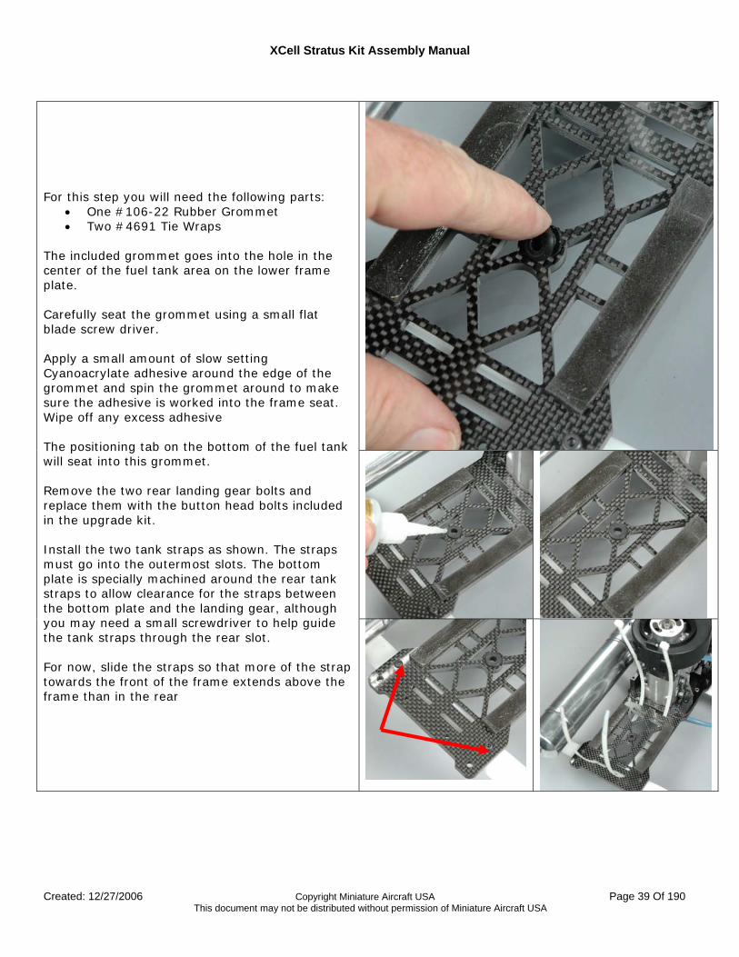
For this step you will need the following parts: • One #106-22 Rubber Grommet • Two #4691 Tie Wraps
The included grommet goes into the hole in the center of the fuel tank area on the lower frame plate. Carefully seat the grommet using a small flat blade screw driver. Apply a small amount of slow setting Cyanoacrylate adhesive around the edge of the grommet and spin the grommet around to make sure the adhesive is worked into the frame seat. Wipe off any excess adhesive The positioning tab on the bottom of the fuel tank will seat into this grommet. Remove the two rear landing gear bolts and replace them with the button head bolts included in the upgrade kit. Install the two tank straps as shown. The straps must go into the outermost slots. The bottom plate is specially machined around the rear tank straps to allow clearance for the straps between the bottom plate and the landing gear, although you may need a small screwdriver to help guide the tank straps through the rear slot. For now, slide the straps so that more of the strap towards the front of the frame extends above the frame than in the rear
XCell Stratus Kit Assembly Manual
Created: 12/27/2006 Copyright Miniature Aircraft USA Page 40 Of 190 This document may not be distributed without permission of Miniature Aircraft USA
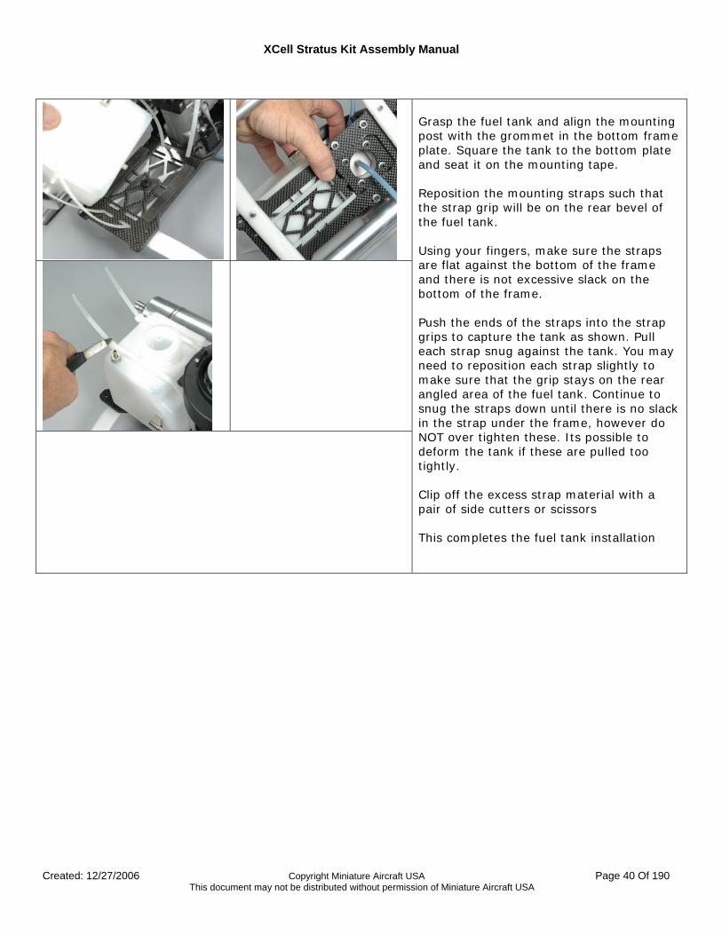
Grasp the fuel tank and align the mounting post with the grommet in the bottom frame plate. Square the tank to the bottom plate and seat it on the mounting tape. Reposition the mounting straps such that the strap grip will be on the rear bevel of the fuel tank. Using your fingers, make sure the straps are flat against the bottom of the frame and there is not excessive slack on the bottom of the frame. Push the ends of the straps into the strap grips to capture the tank as shown. Pull each strap snug against the tank. You may need to reposition each strap slightly to make sure that the grip stays on the rear angled area of the fuel tank. Continue to snug the straps down until there is no slack in the strap under the frame, however do NOT over tighten these. Its possible to deform the tank if these are pulled too tightly. Clip off the excess strap material with a pair of side cutters or scissors This completes the fuel tank installation
XCell Stratus Kit Assembly Manual
Created: 12/27/2006 Copyright Miniature Aircraft USA Page 41 Of 190 This document may not be distributed without permission of Miniature Aircraft USA
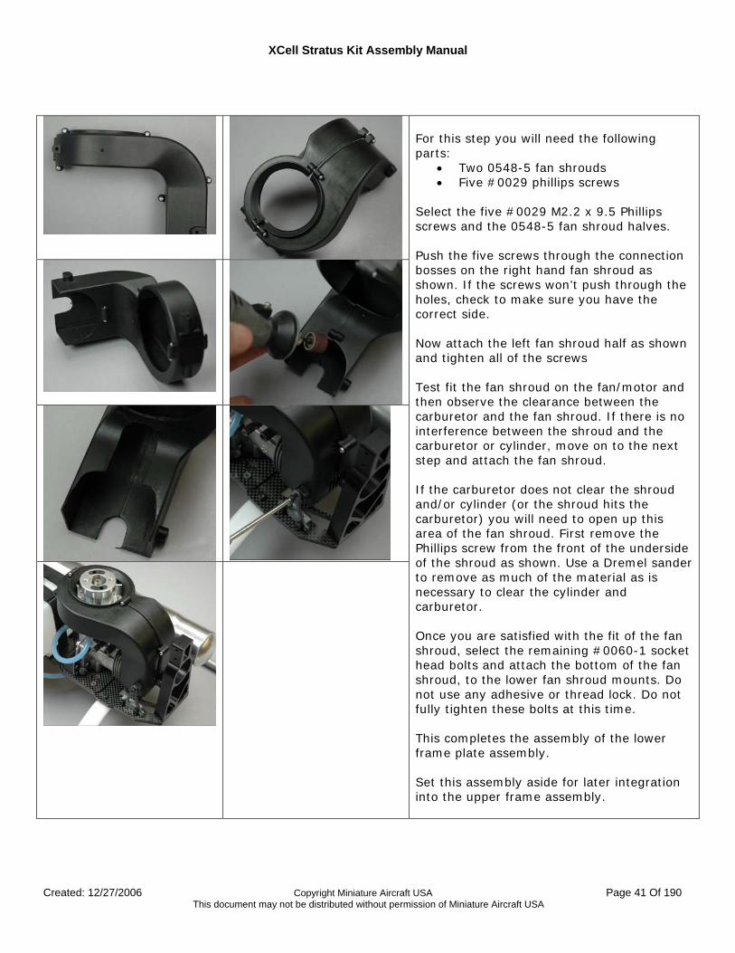
For this step you will need the following parts:
• Two 0548-5 fan shrouds • Five #0029 phillips screws
Select the five #0029 M2.2 x 9.5 Phillips screws and the 0548-5 fan shroud halves. Push the five screws through the connection bosses on the right hand fan shroud as shown. If the screws won’t push through the holes, check to make sure you have the correct side. Now attach the left fan shroud half as shown and tighten all of the screws Test fit the fan shroud on the fan/motor and then observe the clearance between the carburetor and the fan shroud. If there is no interference between the shroud and the carburetor or cylinder, move on to the next step and attach the fan shroud. If the carburetor does not clear the shroud and/or cylinder (or the shroud hits the carburetor) you will need to open up this area of the fan shroud. First remove the Phillips screw from the front of the underside of the shroud as shown. Use a Dremel sander to remove as much of the material as is necessary to clear the cylinder and carburetor. Once you are satisfied with the fit of the fan shroud, select the remaining #0060-1 socket head bolts and attach the bottom of the fan shroud, to the lower fan shroud mounts. Do not use any adhesive or thread lock. Do not fully tighten these bolts at this time. This completes the assembly of the lower frame plate assembly. Set this assembly aside for later integration into the upper frame assembly.
XCell Stratus Kit Assembly Manual
Created: 12/27/2006 Copyright Miniature Aircraft USA Page 42 Of 190 This document may not be distributed without permission of Miniature Aircraft USA
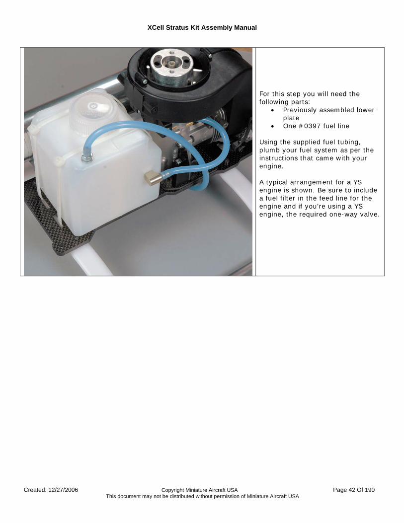
For this step you will need the following parts:
• Previously assembled lower plate
• One #0397 fuel line Using the supplied fuel tubing, plumb your fuel system as per the instructions that came with your engine. A typical arrangement for a YS engine is shown. Be sure to include a fuel filter in the feed line for the engine and if you’re using a YS engine, the required one-way valve.
XCell Stratus Kit Assembly Manual
Created: 12/27/2006 Copyright Miniature Aircraft USA Page 43 Of 190 This document may not be distributed without permission of Miniature Aircraft USA
Upper Frame Assembly This section describes the assembly of the left and right upper frames and their assembly together.
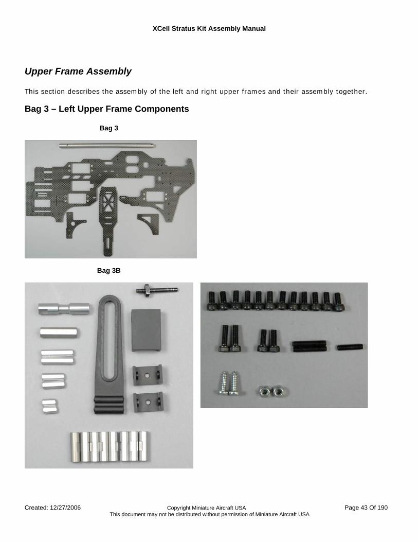
Bag 3 – Left Upper Frame Components
Bag 3
Bag 3B
XCell Stratus Kit Assembly Manual
Created: 12/27/2006 Copyright Miniature Aircraft USA Page 44 Of 190 This document may not be distributed without permission of Miniature Aircraft USA
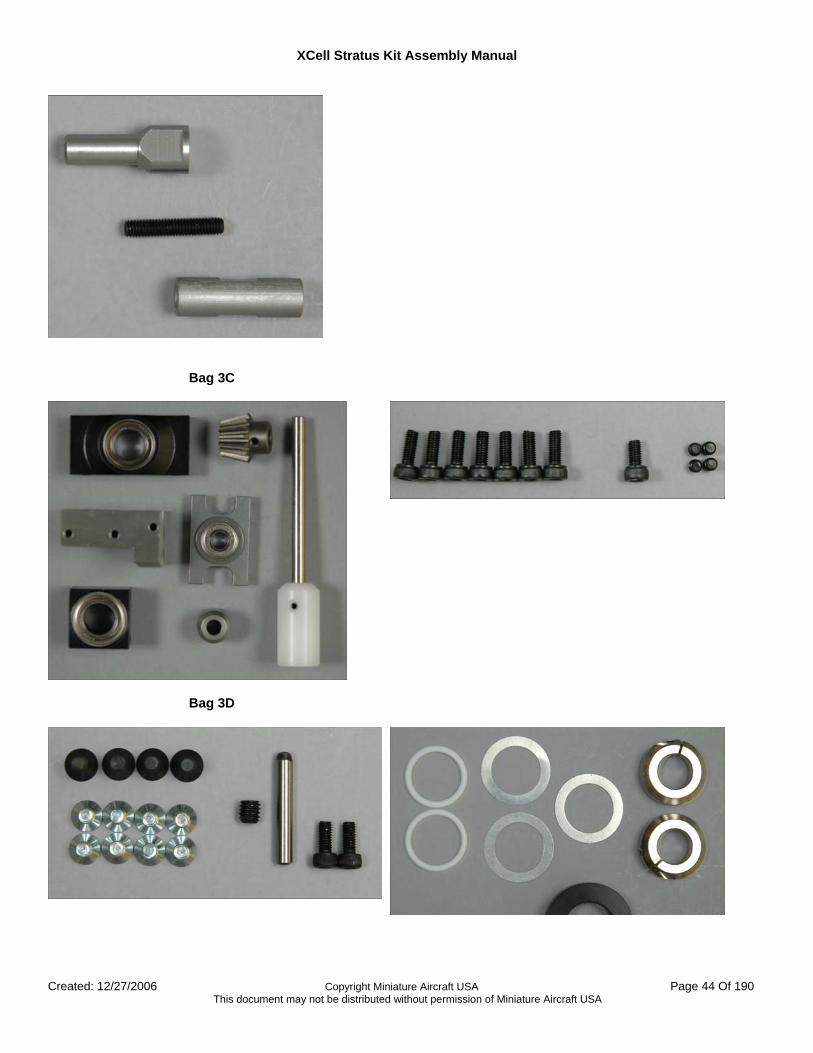
Bag 3C
Bag 3D
XCell Stratus Kit Assembly Manual
Created: 12/27/2006 Copyright Miniature Aircraft USA Page 45 Of 190 This document may not be distributed without permission of Miniature Aircraft USA
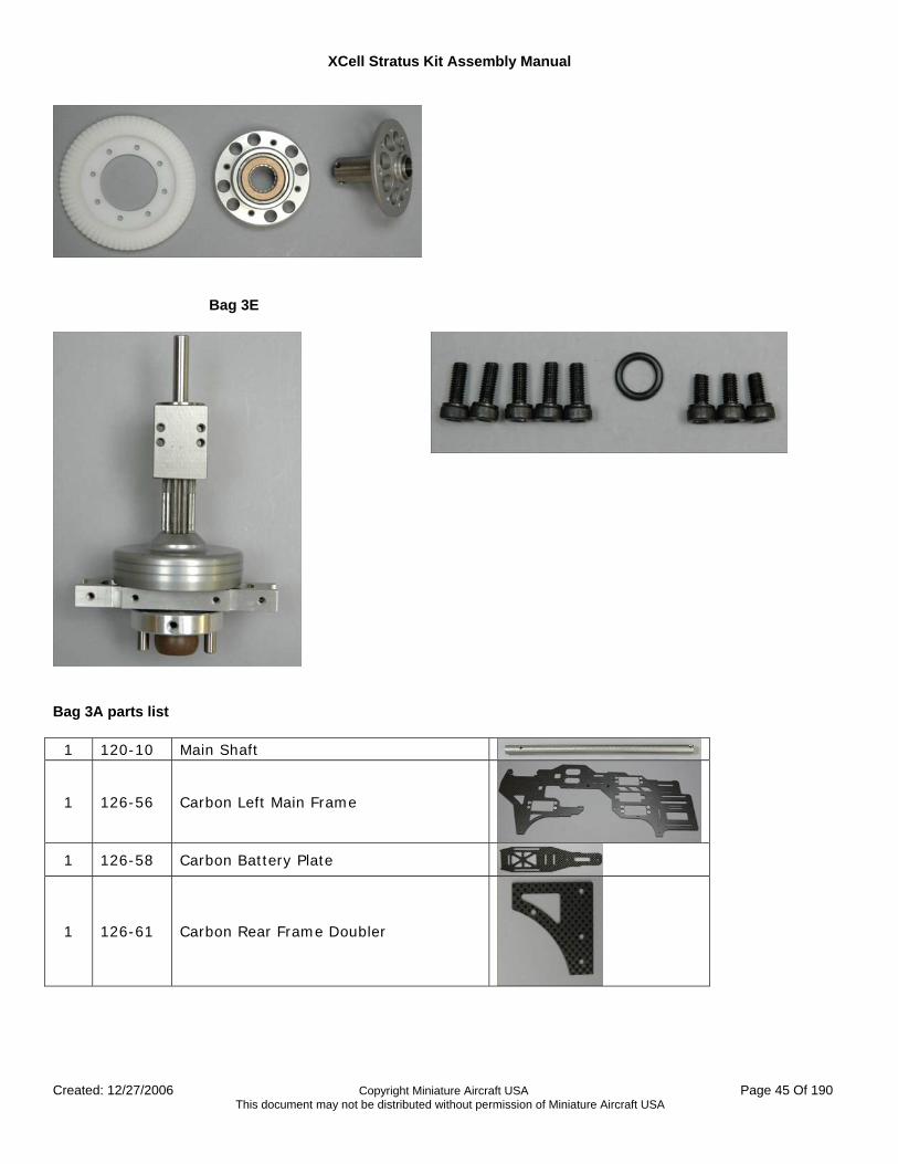
Bag 3E
Bag 3A parts list
1 120-10 Main Shaft
1 126-56 Carbon Left Main Frame
1 126-58 Carbon Battery Plate
1 126-61 Carbon Rear Frame Doubler
XCell Stratus Kit Assembly Manual
Created: 12/27/2006 Copyright Miniature Aircraft USA Page 46 Of 190 This document may not be distributed without permission of Miniature Aircraft USA
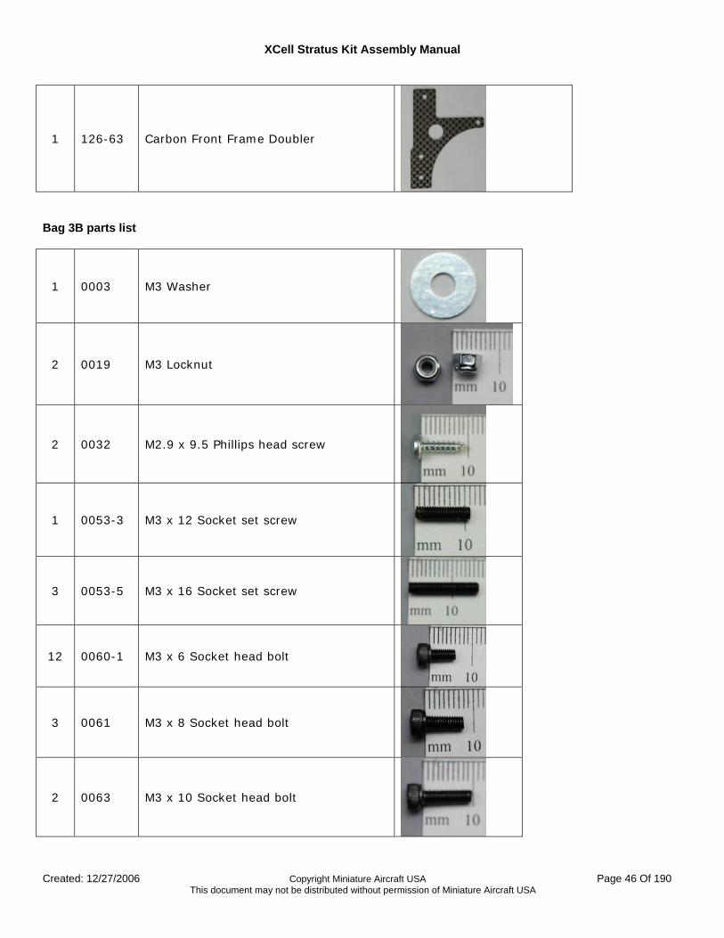
1 126-63 Carbon Front Frame Doubler
Bag 3B parts list
1 0003 M3 Washer
2 0019 M3 Locknut
2 0032 M2.9 x 9.5 Phillips head screw
1 0053-3 M3 x 12 Socket set screw
3 0053-5 M3 x 16 Socket set screw
12 0060-1 M3 x 6 Socket head bolt
3 0061 M3 x 8 Socket head bolt
2 0063 M3 x 10 Socket head bolt
XCell Stratus Kit Assembly Manual
Created: 12/27/2006 Copyright Miniature Aircraft USA Page 47 Of 190 This document may not be distributed without permission of Miniature Aircraft USA
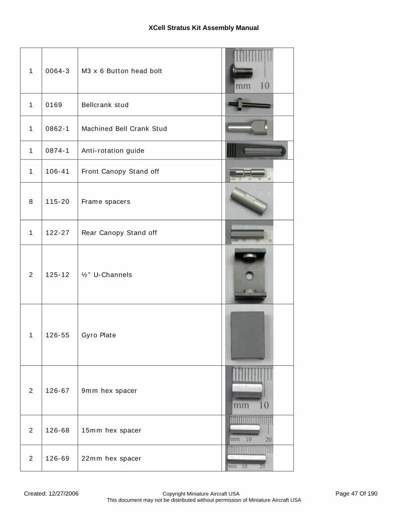
1 0064-3 M3 x 6 Button head bolt
1 0169 Bellcrank stud
1 0862-1 Machined Bell Crank Stud
1 0874-1 Anti-rotation guide
1 106-41 Front Canopy Stand off
8 115-20 Frame spacers
1 122-27 Rear Canopy Stand off
2 125-12 ½” U-Channels
1 126-55 Gyro Plate
2 126-67 9mm hex spacer
2 126-68 15mm hex spacer
2 126-69 22mm hex spacer

XCell Stratus Kit Assembly Manual
Created: 12/27/2006 Copyright Miniature Aircraft USA Page 48 Of 190 This document may not be distributed without permission of Miniature Aircraft USA
Bag 3C parts list
4 0051 M3 x 3 Socket Set screw
1 0060-1 M3 x 6 Socket Head bolt
7 0061 M3 x 8 Socket Head bolt
1 0232 15 Tooth T/R pinion gear
1 115-18 Lower Main Shaft Bearing block
1 120-12 Upper Main Shaft Bearing block
1 120-8 Mainshaft/Tail Drive Bearing block
1 120-9 Front Input shaft
1 123-87 5mm collar
1 126-66 Front T/R Bearing block
Bag 3D parts list
XCell Stratus Kit Assembly Manual
Created: 12/27/2006 Copyright Miniature Aircraft USA Page 49 Of 190 This document may not be distributed without permission of Miniature Aircraft USA
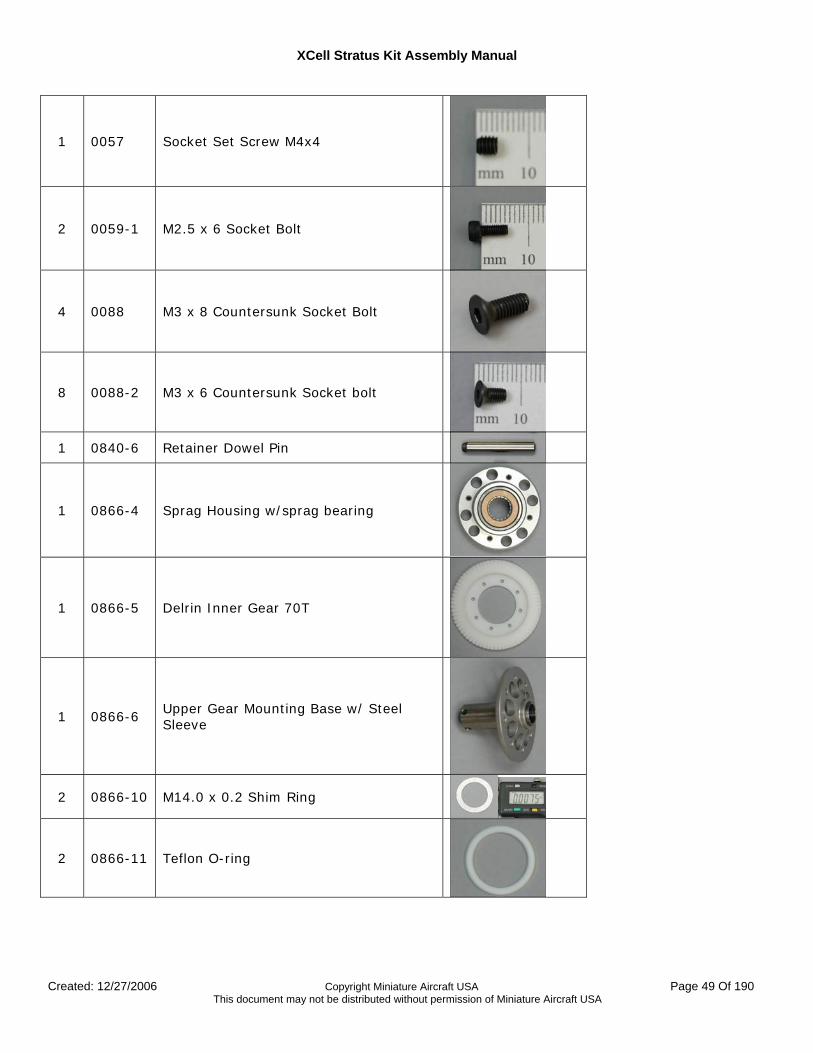
1 0057 Socket Set Screw M4x4
2 0059-1 M2.5 x 6 Socket Bolt
4 0088 M3 x 8 Countersunk Socket Bolt
8 0088-2 M3 x 6 Countersunk Socket bolt
1 0840-6 Retainer Dowel Pin
1 0866-4 Sprag Housing w/sprag bearing
1 0866-5 Delrin Inner Gear 70T
1 0866-6 Upper Gear Mounting Base w/ Steel Sleeve
2 0866-10 M14.0 x 0.2 Shim Ring
2 0866-11 Teflon O-ring
XCell Stratus Kit Assembly Manual
Created: 12/27/2006 Copyright Miniature Aircraft USA Page 50 Of 190 This document may not be distributed without permission of Miniature Aircraft USA
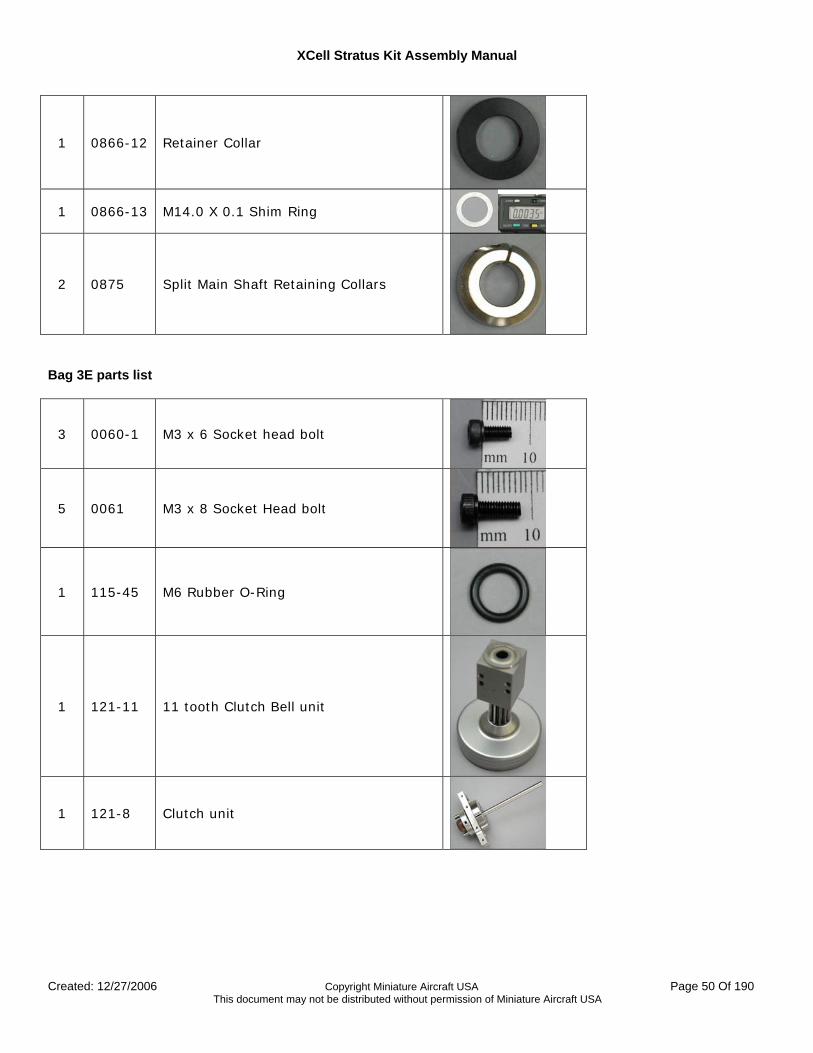
1 0866-12 Retainer Collar
1 0866-13 M14.0 X 0.1 Shim Ring
2 0875 Split Main Shaft Retaining Collars
Bag 3E parts list
3 0060-1 M3 x 6 Socket head bolt
5 0061 M3 x 8 Socket Head bolt
1 115-45 M6 Rubber O-Ring
1 121-11 11 tooth Clutch Bell unit
1 121-8 Clutch unit
XCell Stratus Kit Assembly Manual
Created: 12/27/2006 Copyright Miniature Aircraft USA Page 51 Of 190 This document may not be distributed without permission of Miniature Aircraft USA
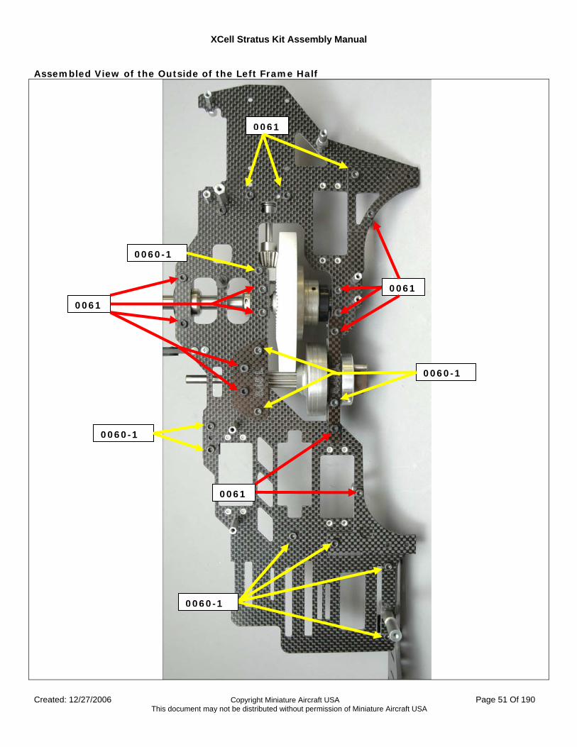
Assembled View of the Outside of the Left Frame Half
0060-1
0061
0060-1
0061
0060-1
0061
0061
0060-1
XCell Stratus Kit Assembly Manual
Created: 12/27/2006 Copyright Miniature Aircraft USA Page 52 Of 190 This document may not be distributed without permission of Miniature Aircraft USA
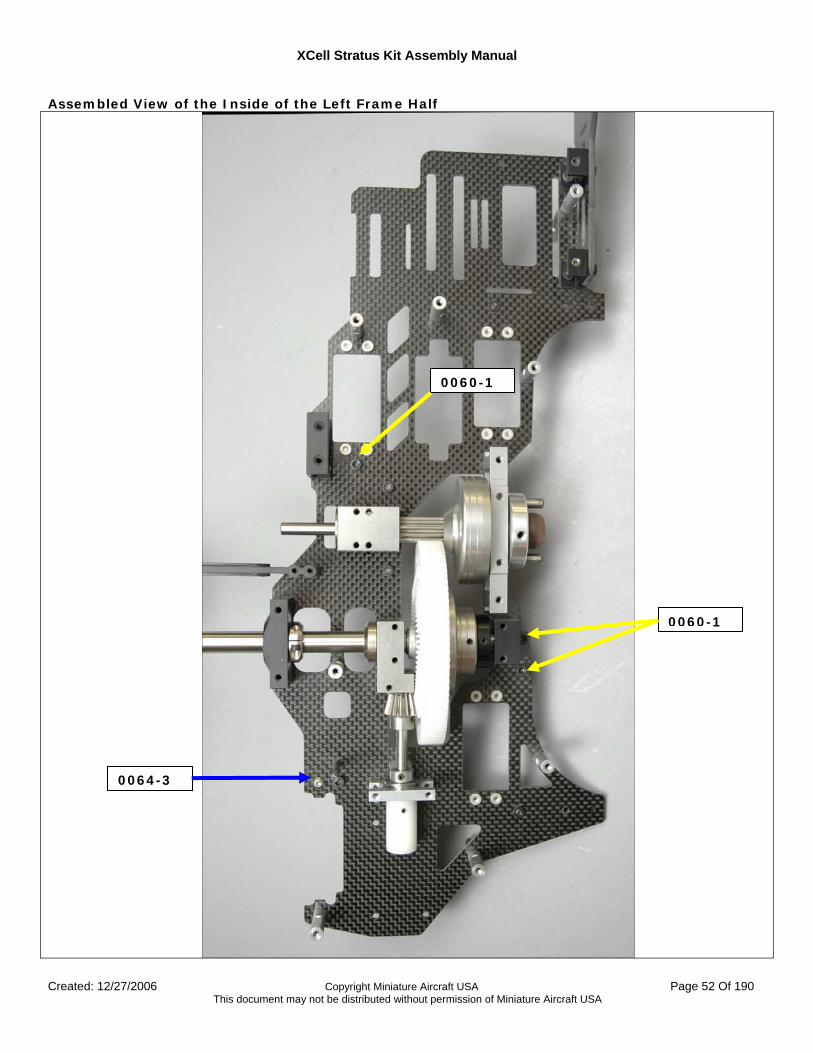
Assembled View of the Inside of the Left Frame Half
0060-1
0060-1
0064-3
XCell Stratus Kit Assembly Manual
Created: 12/27/2006 Copyright Miniature Aircraft USA Page 53 Of 190 This document may not be distributed without permission of Miniature Aircraft USA
Assembly Steps
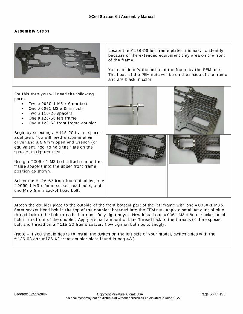
Locate the #126-56 left frame plate. It is easy to identify because of the extended equipment tray area on the front of the frame. You can identify the inside of the frame by the PEM nuts. The head of the PEM nuts will be on the inside of the frame and are black in color
For this step you will need the following parts:
• Two #0060-1 M3 x 6mm bolt • One #0061 M3 x 8mm bolt • Two #115-20 spacers • One #126-56 left frame • One #126-63 front frame doubler
Begin by selecting a #115-20 frame spacer as shown. You will need a 2.5mm allen driver and a 5.5mm open end wrench (or equivalent) tool to hold the flats on the spacers to tighten them. Using a #0060-1 M3 bolt, attach one of the frame spacers into the upper front frame position as shown. Select the #126-63 front frame doubler, one #0060-1 M3 x 6mm socket head bolts, and one M3 x 8mm socket head bolt.
Attach the doubler plate to the outside of the front bottom part of the left frame with one #0060-1 M3 x 6mm socket head bolt in the top of the doubler threaded into the PEM nut. Apply a small amount of blue thread lock to the bolt threads, but don’t fully tighten yet. Now install one #0061 M3 x 8mm socket head bolt in the front of the doubler. Apply a small amount of blue Thread lock to the threads of the exposed bolt and thread on a #115-20 frame spacer. Now tighten both bolts snugly. (Note – if you should desire to install the switch on the left side of your model, switch sides with the #126-63 and #126-62 front doubler plate found in bag 4A.)
XCell Stratus Kit Assembly Manual
Created: 12/27/2006 Copyright Miniature Aircraft USA Page 54 Of 190 This document may not be distributed without permission of Miniature Aircraft USA
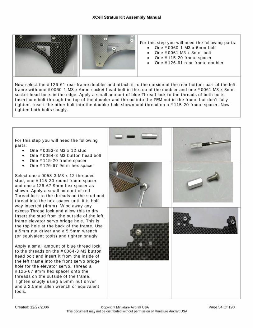
For this step you will need the following parts:
• One #0060-1 M3 x 6mm bolt • One #0061 M3 x 8mm bolt • One #115-20 frame spacer • One #126-61 rear frame doubler
Now select the #126-61 rear frame doubler and attach it to the outside of the rear bottom part of the left frame with one #0060-1 M3 x 6mm socket head bolt in the top of the doubler and one #0061 M3 x 8mm socket head bolts in the edge. Apply a small amount of blue Thread lock to the threads of both bolts. Insert one bolt through the top of the doubler and thread into the PEM nut in the frame but don’t fully tighten. Insert the other bolt into the doubler hole shown and thread on a #115-20 frame spacer. Now tighten both bolts snugly.
For this step you will need the following parts:
• One #0053-3 M3 x 12 stud • One #0064-3 M3 button head bolt • One #115-20 frame spacer • One #126-67 9mm hex spacer
Select one #0053-3 M3 x 12 threaded stud, one #115-20 round frame spacer and one #126-67 9mm hex spacer as shown. Apply a small amount of red Thread lock to the threads on the stud and thread into the hex spacer until it is half way inserted (4mm). Wipe away any excess Thread lock and allow this to dry. Insert the stud from the outside of the left frame elevator servo bridge hole. This is the top hole at the back of the frame. Use a 5mm nut driver and a 5.5mm wrench (or equivalent tools) and tighten snugly Apply a small amount of blue thread lock to the threads on the #0064-3 M3 button head bolt and insert it from the inside of the left frame into the front servo bridge hole for the elevator servo. Thread a #126-67 9mm hex spacer onto the threads on the outside of the frame. Tighten snugly using a 5mm nut driver and a 2.5mm allen wrench or equivalent tools.
XCell Stratus Kit Assembly Manual
Created: 12/27/2006 Copyright Miniature Aircraft USA Page 55 Of 190 This document may not be distributed without permission of Miniature Aircraft USA
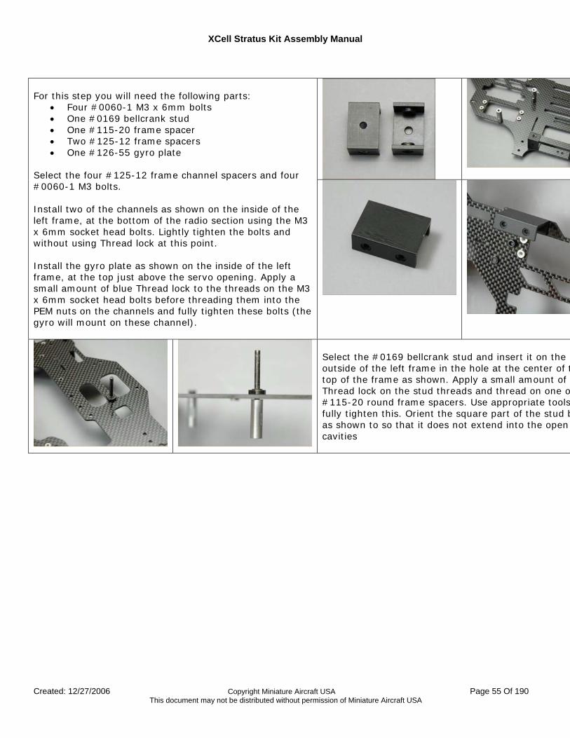
For this step you will need the following parts:
• Four #0060-1 M3 x 6mm bolts • One #0169 bellcrank stud • One #115-20 frame spacer • Two #125-12 frame spacers • One #126-55 gyro plate
Select the four #125-12 frame channel spacers and four #0060-1 M3 bolts. Install two of the channels as shown on the inside of the left frame, at the bottom of the radio section using the M3 x 6mm socket head bolts. Lightly tighten the bolts and without using Thread lock at this point. Install the gyro plate as shown on the inside of the left frame, at the top just above the servo opening. Apply a small amount of blue Thread lock to the threads on the M3 x 6mm socket head bolts before threading them into the PEM nuts on the channels and fully tighten these bolts (the gyro will mount on these channel).
Select the #0169 bellcrank stud and insert it on the outside of the left frame in the hole at the center of ttop of the frame as shown. Apply a small amount of Thread lock on the stud threads and thread on one o#115-20 round frame spacers. Use appropriate toolsfully tighten this. Orient the square part of the stud bas shown to so that it does not extend into the open cavities
XCell Stratus Kit Assembly Manual
Created: 12/27/2006 Copyright Miniature Aircraft USA Page 56 Of 190 This document may not be distributed without permission of Miniature Aircraft USA
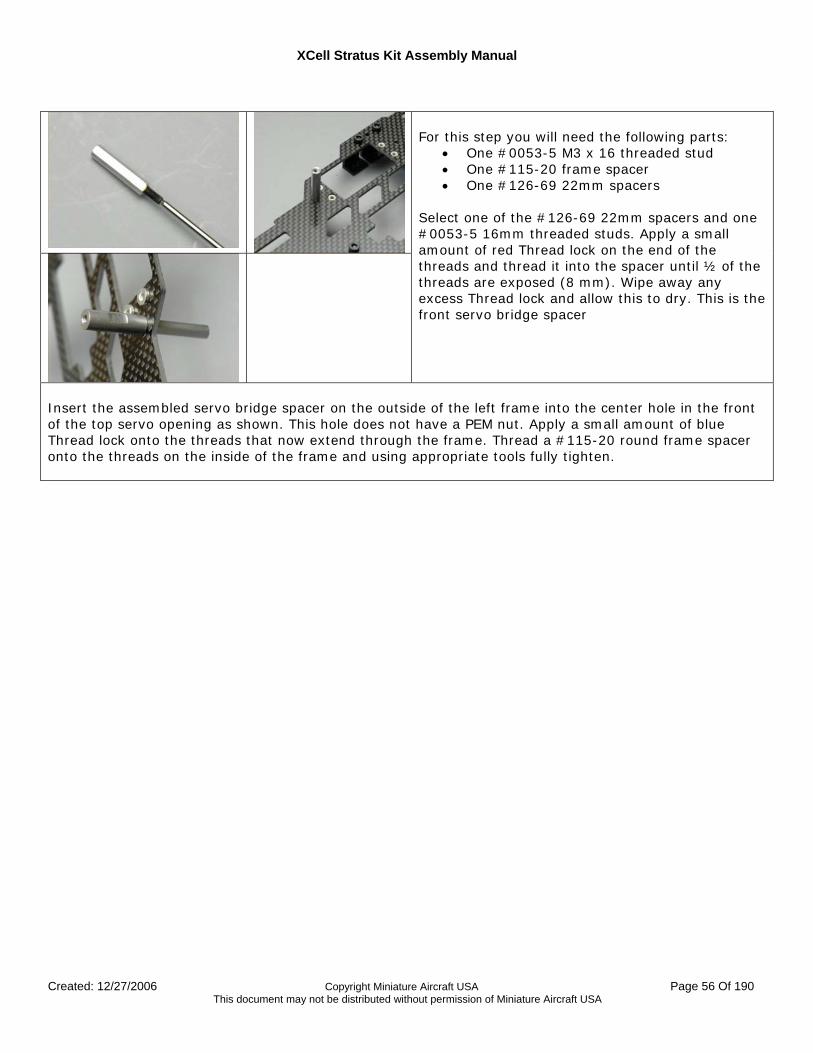
For this step you will need the following parts:
• One #0053-5 M3 x 16 threaded stud • One #115-20 frame spacer • One #126-69 22mm spacers
Select one of the #126-69 22mm spacers and one #0053-5 16mm threaded studs. Apply a small amount of red Thread lock on the end of the threads and thread it into the spacer until ½ of the threads are exposed (8 mm). Wipe away any excess Thread lock and allow this to dry. This is the front servo bridge spacer
Insert the assembled servo bridge spacer on the outside of the left frame into the center hole in the front of the top servo opening as shown. This hole does not have a PEM nut. Apply a small amount of blue Thread lock onto the threads that now extend through the frame. Thread a #115-20 round frame spacer onto the threads on the inside of the frame and using appropriate tools fully tighten.
XCell Stratus Kit Assembly Manual
Created: 12/27/2006 Copyright Miniature Aircraft USA Page 57 Of 190 This document may not be distributed without permission of Miniature Aircraft USA
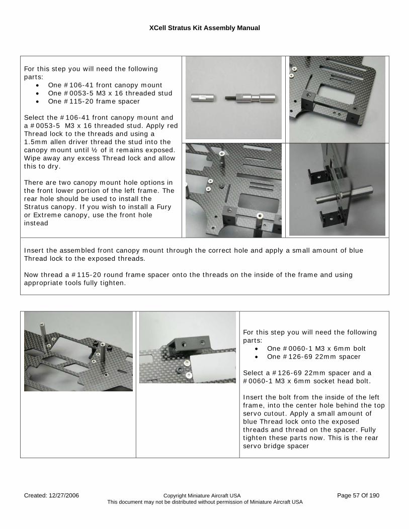
For this step you will need the following parts:
• One #106-41 front canopy mount • One #0053-5 M3 x 16 threaded stud • One #115-20 frame spacer
Select the #106-41 front canopy mount and a #0053-5 M3 x 16 threaded stud. Apply red Thread lock to the threads and using a 1.5mm allen driver thread the stud into the canopy mount until ½ of it remains exposed. Wipe away any excess Thread lock and allow this to dry. There are two canopy mount hole options in the front lower portion of the left frame. The rear hole should be used to install the Stratus canopy. If you wish to install a Fury or Extreme canopy, use the front hole instead Insert the assembled front canopy mount through the correct hole and apply a small amount of blue Thread lock to the exposed threads. Now thread a #115-20 round frame spacer onto the threads on the inside of the frame and using appropriate tools fully tighten.
For this step you will need the following parts:
• One #0060-1 M3 x 6mm bolt • One #126-69 22mm spacer
Select a #126-69 22mm spacer and a #0060-1 M3 x 6mm socket head bolt. Insert the bolt from the inside of the left frame, into the center hole behind the top servo cutout. Apply a small amount of blue Thread lock onto the exposed threads and thread on the spacer. Fully tighten these parts now. This is the rear servo bridge spacer

XCell Stratus Kit Assembly Manual
Created: 12/27/2006 Copyright Miniature Aircraft USA Page 58 Of 190 This document may not be distributed without permission of Miniature Aircraft USA
For this step you will need the following parts:
• Two #126-68 15mm spacers • Two #0060-1 M3 x 6mm bolts
Select two of the #126-68 15mm spacers and two #0060-1 M3 x 6mm socket head bolts.
Insert the two bolts from the inside of the left frame through the two holes at the bottom of the gear drive cutout. Apply a small amount of blue Thread lock to the threads and thread the fan shroud spacers onto the bolts on the outside of the frame. Fully tighten using appropriate tools. These are the mounts for the fan shroud plate.
XCell Stratus Kit Assembly Manual
Created: 12/27/2006 Copyright Miniature Aircraft USA Page 59 Of 190 This document may not be distributed without permission of Miniature Aircraft USA
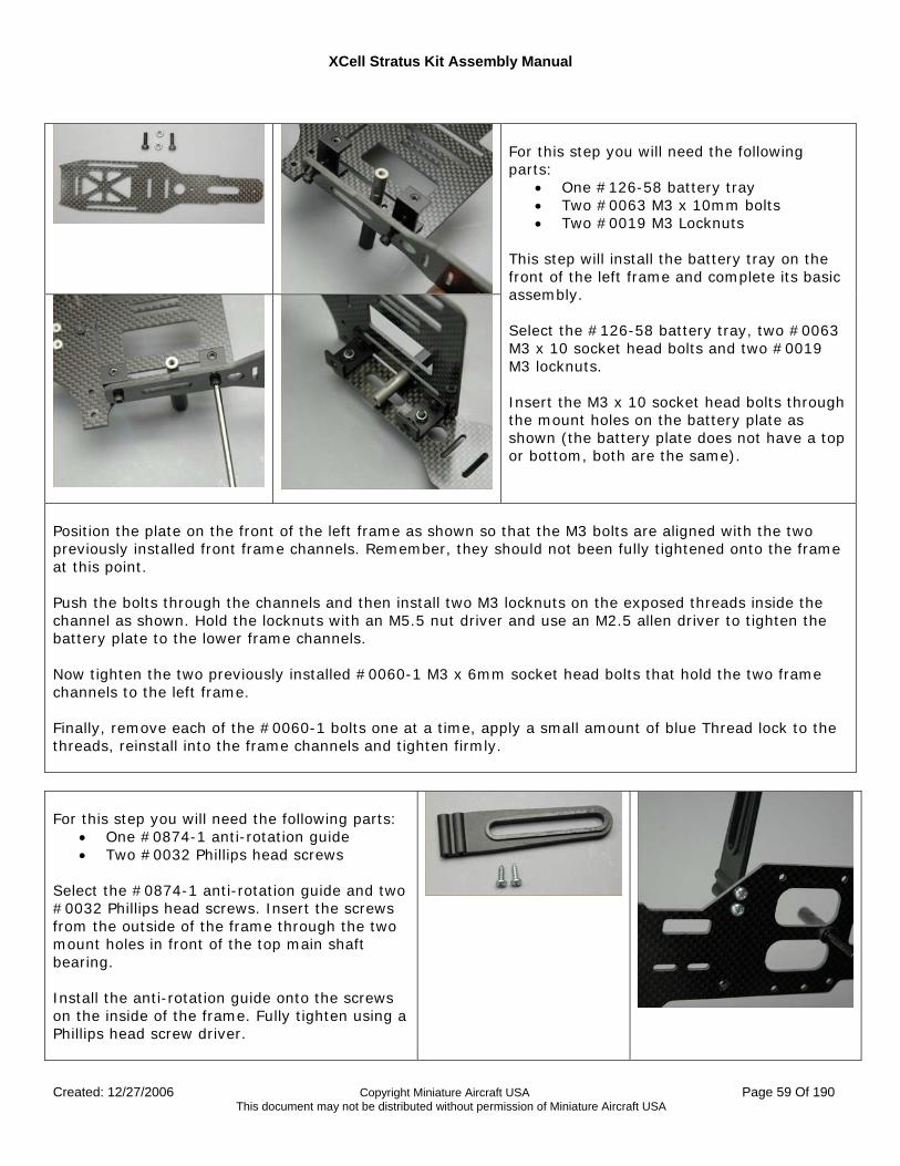
For this step you will need the following parts:
• One #126-58 battery tray • Two #0063 M3 x 10mm bolts • Two #0019 M3 Locknuts
This step will install the battery tray on the front of the left frame and complete its basic assembly. Select the #126-58 battery tray, two #0063 M3 x 10 socket head bolts and two #0019 M3 locknuts. Insert the M3 x 10 socket head bolts through the mount holes on the battery plate as shown (the battery plate does not have a top or bottom, both are the same).
Position the plate on the front of the left frame as shown so that the M3 bolts are aligned with the two previously installed front frame channels. Remember, they should not been fully tightened onto the frame at this point. Push the bolts through the channels and then install two M3 locknuts on the exposed threads inside the channel as shown. Hold the locknuts with an M5.5 nut driver and use an M2.5 allen driver to tighten the battery plate to the lower frame channels. Now tighten the two previously installed #0060-1 M3 x 6mm socket head bolts that hold the two frame channels to the left frame. Finally, remove each of the #0060-1 bolts one at a time, apply a small amount of blue Thread lock to the threads, reinstall into the frame channels and tighten firmly. For this step you will need the following parts:
• One #0874-1 anti-rotation guide • Two #0032 Phillips head screws
Select the #0874-1 anti-rotation guide and two #0032 Phillips head screws. Insert the screws from the outside of the frame through the two mount holes in front of the top main shaft bearing. Install the anti-rotation guide onto the screws on the inside of the frame. Fully tighten using a Phillips head screw driver.
XCell Stratus Kit Assembly Manual
Created: 12/27/2006 Copyright Miniature Aircraft USA Page 60 Of 190 This document may not be distributed without permission of Miniature Aircraft USA
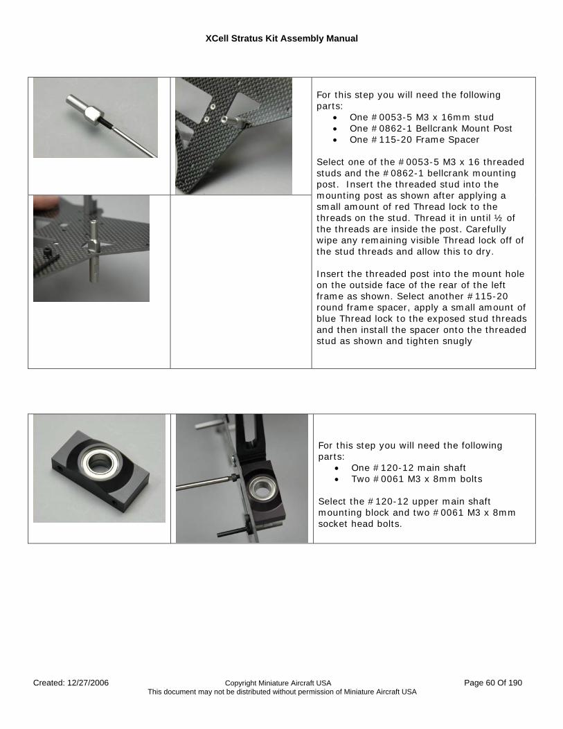
For this step you will need the following parts:
• One #0053-5 M3 x 16mm stud • One #0862-1 Bellcrank Mount Post • One #115-20 Frame Spacer
Select one of the #0053-5 M3 x 16 threaded studs and the #0862-1 bellcrank mounting post. Insert the threaded stud into the mounting post as shown after applying a small amount of red Thread lock to the threads on the stud. Thread it in until ½ of the threads are inside the post. Carefully wipe any remaining visible Thread lock off of the stud threads and allow this to dry. Insert the threaded post into the mount hole on the outside face of the rear of the left frame as shown. Select another #115-20 round frame spacer, apply a small amount of blue Thread lock to the exposed stud threads and then install the spacer onto the threaded stud as shown and tighten snugly
For this step you will need the following parts:
• One #120-12 main shaft • Two #0061 M3 x 8mm bolts
Select the #120-12 upper main shaft mounting block and two #0061 M3 x 8mm socket head bolts.
XCell Stratus Kit Assembly Manual
Created: 12/27/2006 Copyright Miniature Aircraft USA Page 61 Of 190 This document may not be distributed without permission of Miniature Aircraft USA
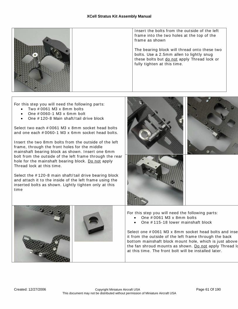
Insert the bolts from the outside of the left frame into the two holes at the top of the frame as shown The bearing block will thread onto these two bolts. Use a 2.5mm allen to lightly snug these bolts but do not apply Thread lock or fully tighten at this time.
For this step you will need the following parts:
• Two #0061 M3 x 8mm bolts • One #0060-1 M3 x 6mm bolt • One #120-8 Main shaft/tail drive block
Select two each #0061 M3 x 8mm socket head bolts and one each #0060-1 M3 x 6mm socket head bolts. Insert the two 8mm bolts from the outside of the left frame, through the front holes for the middle mainshaft bearing block as shown. Insert one 6mm bolt from the outside of the left frame through the rear hole for the mainshaft bearing block. Do not apply Thread lock at this time. Select the #120-8 main shaft/tail drive bearing block and attach it to the inside of the left frame using the inserted bolts as shown. Lightly tighten only at this time
For this step you will need the following parts:
• One #0061 M3 x 8mm bolts • One #115-18 lower mainshaft block
Select one #0061 M3 x 8mm socket head bolts and inserit from the outside of the left frame through the back bottom mainshaft block mount hole, which is just above the fan shroud mounts as shown. Do not apply Thread loat this time. The front bolt will be installed later.
XCell Stratus Kit Assembly Manual
Created: 12/27/2006 Copyright Miniature Aircraft USA Page 62 Of 190 This document may not be distributed without permission of Miniature Aircraft USA
Select the #115-18 lower mainshaft bearing block and attach it as shown to the inside of the left frame using thinserted bolt. Note that the bearing will be facing the bottom of the frame. Lightly tighten only at this time.
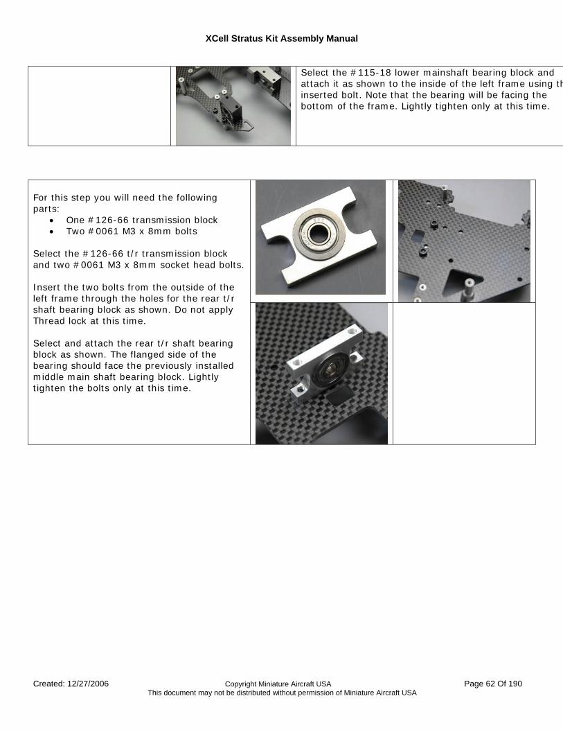
For this step you will need the following parts:
• One #126-66 transmission block • Two #0061 M3 x 8mm bolts
Select the #126-66 t/r transmission block and two #0061 M3 x 8mm socket head bolts. Insert the two bolts from the outside of the left frame through the holes for the rear t/r shaft bearing block as shown. Do not apply Thread lock at this time. Select and attach the rear t/r shaft bearing block as shown. The flanged side of the bearing should face the previously installed middle main shaft bearing block. Lightly tighten the bolts only at this time.
XCell Stratus Kit Assembly Manual
Created: 12/27/2006 Copyright Miniature Aircraft USA Page 63 Of 190 This document may not be distributed without permission of Miniature Aircraft USA
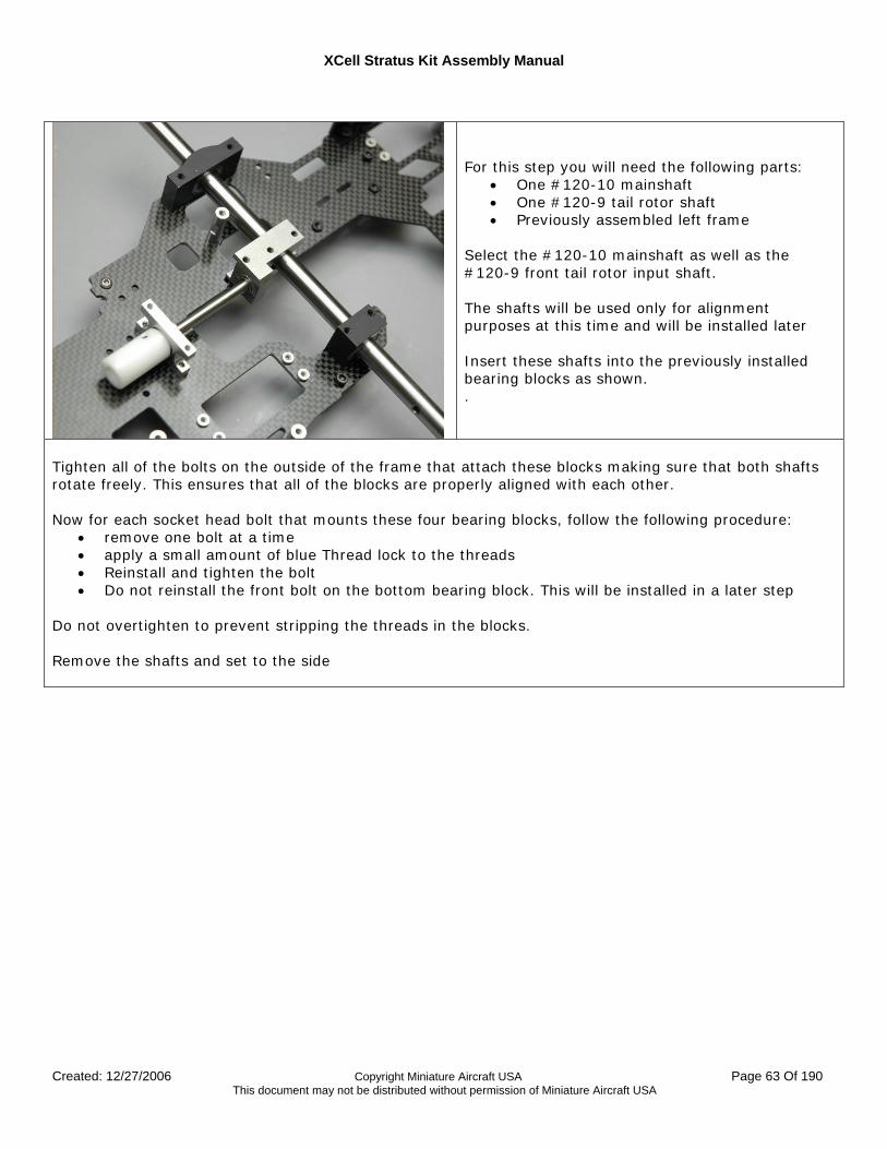
For this step you will need the following parts:
• One #120-10 mainshaft • One #120-9 tail rotor shaft • Previously assembled left frame
Select the #120-10 mainshaft as well as the #120-9 front tail rotor input shaft. The shafts will be used only for alignment purposes at this time and will be installed later Insert these shafts into the previously installed bearing blocks as shown. .
Tighten all of the bolts on the outside of the frame that attach these blocks making sure that both shafts rotate freely. This ensures that all of the blocks are properly aligned with each other. Now for each socket head bolt that mounts these four bearing blocks, follow the following procedure:
• remove one bolt at a time • apply a small amount of blue Thread lock to the threads • Reinstall and tighten the bolt • Do not reinstall the front bolt on the bottom bearing block. This will be installed in a later step
Do not overtighten to prevent stripping the threads in the blocks. Remove the shafts and set to the side
XCell Stratus Kit Assembly Manual
Created: 12/27/2006 Copyright Miniature Aircraft USA Page 64 Of 190 This document may not be distributed without permission of Miniature Aircraft USA
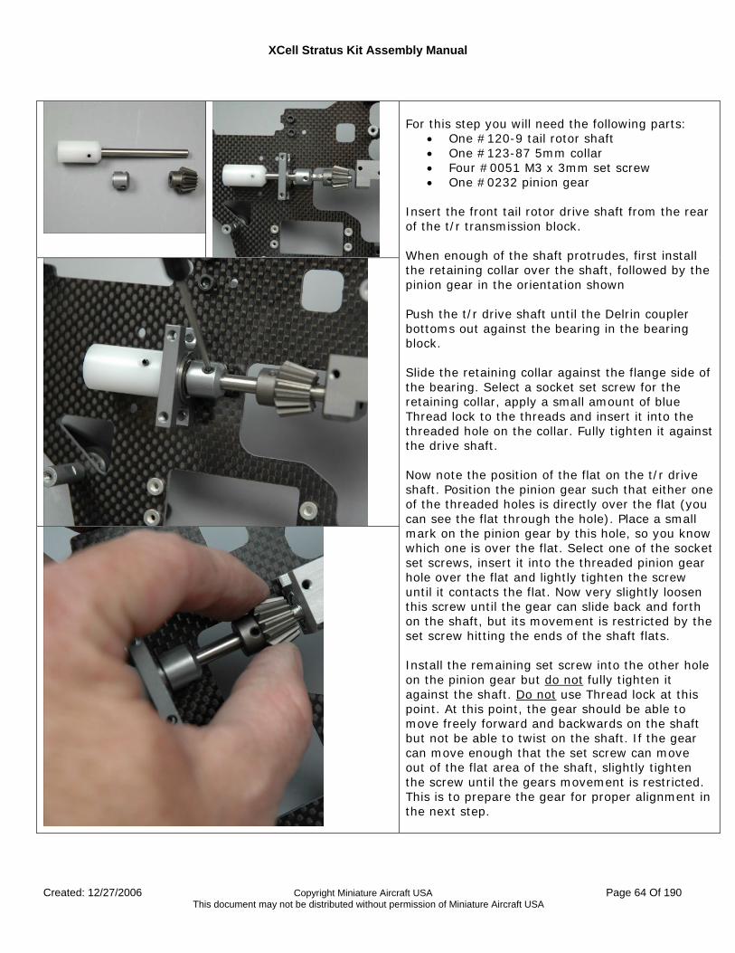
For this step you will need the following parts:
• One #120-9 tail rotor shaft • One #123-87 5mm collar • Four #0051 M3 x 3mm set screw • One #0232 pinion gear
Insert the front tail rotor drive shaft from the rear of the t/r transmission block. When enough of the shaft protrudes, first install the retaining collar over the shaft, followed by the pinion gear in the orientation shown Push the t/r drive shaft until the Delrin coupler bottoms out against the bearing in the bearing block. Slide the retaining collar against the flange side of the bearing. Select a socket set screw for the retaining collar, apply a small amount of blue Thread lock to the threads and insert it into the threaded hole on the collar. Fully tighten it against the drive shaft. Now note the position of the flat on the t/r drive shaft. Position the pinion gear such that either one of the threaded holes is directly over the flat (you can see the flat through the hole). Place a small mark on the pinion gear by this hole, so you know which one is over the flat. Select one of the socket set screws, insert it into the threaded pinion gear hole over the flat and lightly tighten the screw until it contacts the flat. Now very slightly loosen this screw until the gear can slide back and forth on the shaft, but its movement is restricted by the set screw hitting the ends of the shaft flats. Install the remaining set screw into the other hole on the pinion gear but do not fully tighten it against the shaft. Do not use Thread lock at this point. At this point, the gear should be able to move freely forward and backwards on the shaft but not be able to twist on the shaft. If the gear can move enough that the set screw can move out of the flat area of the shaft, slightly tighten the screw until the gears movement is restricted. This is to prepare the gear for proper alignment in the next step.
XCell Stratus Kit Assembly Manual
Created: 12/27/2006 Copyright Miniature Aircraft USA Page 65 Of 190 This document may not be distributed without permission of Miniature Aircraft USA
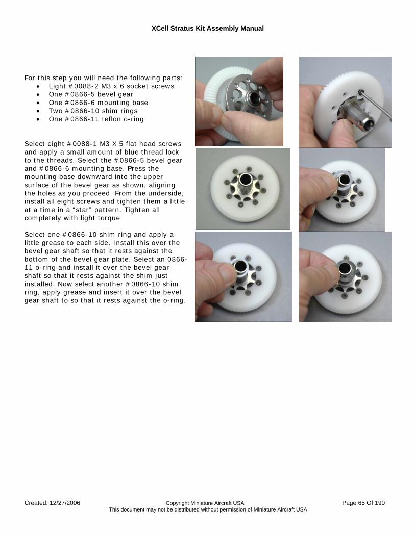
For this step you will need the following parts:
• Eight #0088-2 M3 x 6 socket screws • One #0866-5 bevel gear • One #0866-6 mounting base • Two #0866-10 shim rings • One #0866-11 teflon o-ring
Select eight #0088-1 M3 X 5 flat head screws and apply a small amount of blue thread lock to the threads. Select the #0866-5 bevel gear and #0866-6 mounting base. Press the mounting base downward into the upper surface of the bevel gear as shown, aligning the holes as you proceed. From the underside, install all eight screws and tighten them a little at a time in a “star” pattern. Tighten all completely with light torque Select one #0866-10 shim ring and apply a little grease to each side. Install this over the bevel gear shaft so that it rests against the bottom of the bevel gear plate. Select an 0866-11 o-ring and install it over the bevel gear shaft so that it rests against the shim just installed. Now select another #0866-10 shim ring, apply grease and insert it over the bevel gear shaft to so that it rests against the o-ring.
XCell Stratus Kit Assembly Manual
Created: 12/27/2006 Copyright Miniature Aircraft USA Page 66 Of 190 This document may not be distributed without permission of Miniature Aircraft USA
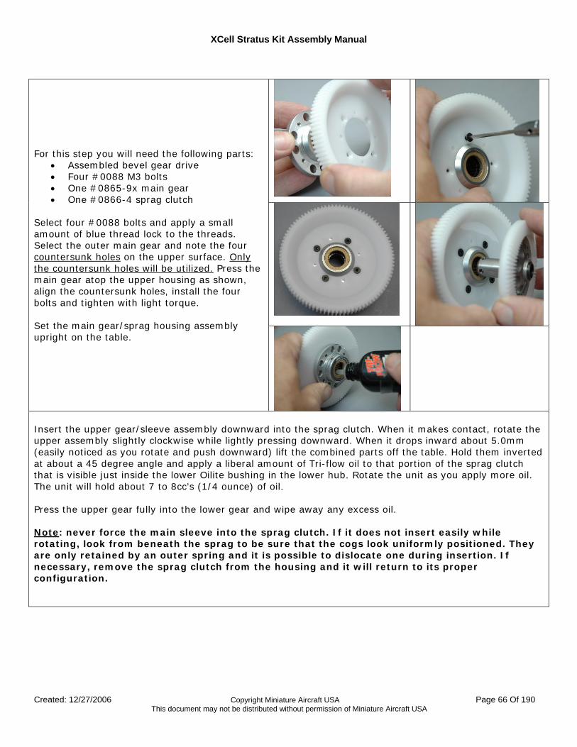
For this step you will need the following parts: • Assembled bevel gear drive • Four #0088 M3 bolts • One #0865-9x main gear • One #0866-4 sprag clutch
Select four #0088 bolts and apply a small amount of blue thread lock to the threads. Select the outer main gear and note the four countersunk holes on the upper surface. Only the countersunk holes will be utilized. Press the main gear atop the upper housing as shown, align the countersunk holes, install the four bolts and tighten with light torque. Set the main gear/sprag housing assembly upright on the table.
Insert the upper gear/sleeve assembly downward into the sprag clutch. When it makes contact, rotate the upper assembly slightly clockwise while lightly pressing downward. When it drops inward about 5.0mm (easily noticed as you rotate and push downward) lift the combined parts off the table. Hold them inverted at about a 45 degree angle and apply a liberal amount of Tri-flow oil to that portion of the sprag clutch that is visible just inside the lower Oilite bushing in the lower hub. Rotate the unit as you apply more oil. The unit will hold about 7 to 8cc’s (1/4 ounce) of oil. Press the upper gear fully into the lower gear and wipe away any excess oil. Note: never force the main sleeve into the sprag clutch. If it does not insert easily while rotating, look from beneath the sprag to be sure that the cogs look uniformly positioned. They are only retained by an outer spring and it is possible to dislocate one during insertion. If necessary, remove the sprag clutch from the housing and it will return to its proper configuration.
XCell Stratus Kit Assembly Manual
Created: 12/27/2006 Copyright Miniature Aircraft USA Page 67 Of 190 This document may not be distributed without permission of Miniature Aircraft USA
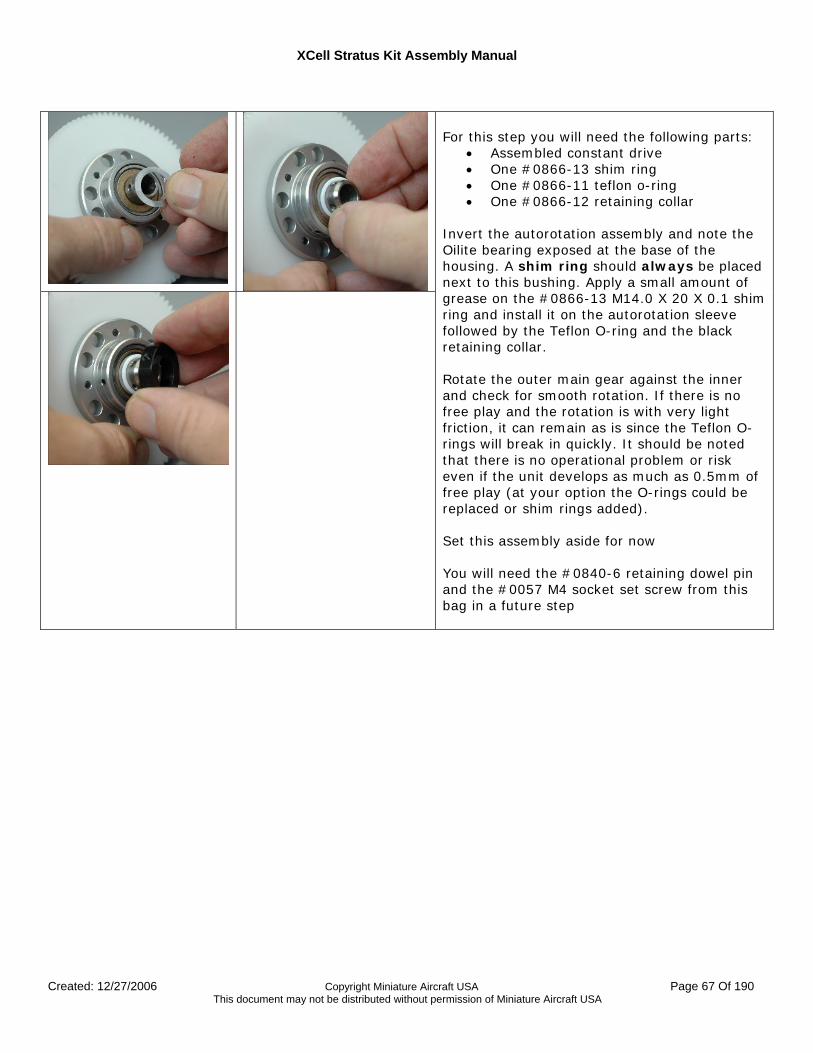
For this step you will need the following parts:
• Assembled constant drive • One #0866-13 shim ring • One #0866-11 teflon o-ring • One #0866-12 retaining collar
Invert the autorotation assembly and note the Oilite bearing exposed at the base of the housing. A shim ring should always be placed next to this bushing. Apply a small amount of grease on the #0866-13 M14.0 X 20 X 0.1 shim ring and install it on the autorotation sleeve followed by the Teflon O-ring and the black retaining collar. Rotate the outer main gear against the inner and check for smooth rotation. If there is no free play and the rotation is with very light friction, it can remain as is since the Teflon O-rings will break in quickly. It should be noted that there is no operational problem or risk even if the unit develops as much as 0.5mm of free play (at your option the O-rings could be replaced or shim rings added). Set this assembly aside for now You will need the #0840-6 retaining dowel pin and the #0057 M4 socket set screw from this bag in a future step
XCell Stratus Kit Assembly Manual
Created: 12/27/2006 Copyright Miniature Aircraft USA Page 68 Of 190 This document may not be distributed without permission of Miniature Aircraft USA
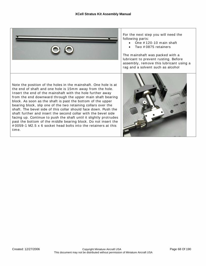
For the next step you will need the following parts:
• One #120-10 main shaft • Two #0875 retainers
The mainshaft was packed with a lubricant to prevent rusting. Before assembly, remove this lubricant using a rag and a solvent such as alcohol
Note the position of the holes in the mainshaft. One hole is at the end of shaft and one hole is 15mm away from the hole. Insert the end of the mainshaft with the hole further away from the end downward through the upper main shaft bearing block. As soon as the shaft is past the bottom of the upper bearing block, slip one of the two retaining collars over the shaft. The bevel side of this collar should face down. Push the shaft further and insert the second collar with the bevel side facing up. Continue to push the shaft until it slightly protrudes past the bottom of the middle bearing block. Do not insert the #0059-1 M2.5 x 6 socket head bolts into the retainers at this time.
XCell Stratus Kit Assembly Manual
Created: 12/27/2006 Copyright Miniature Aircraft USA Page 69 Of 190 This document may not be distributed without permission of Miniature Aircraft USA
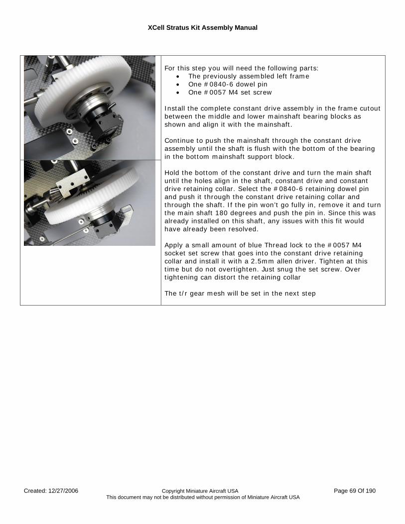
For this step you will need the following parts:
• The previously assembled left frame • One #0840-6 dowel pin • One #0057 M4 set screw
Install the complete constant drive assembly in the frame cutout between the middle and lower mainshaft bearing blocks as shown and align it with the mainshaft. Continue to push the mainshaft through the constant drive assembly until the shaft is flush with the bottom of the bearing in the bottom mainshaft support block. Hold the bottom of the constant drive and turn the main shaft until the holes align in the shaft, constant drive and constant drive retaining collar. Select the #0840-6 retaining dowel pin and push it through the constant drive retaining collar and through the shaft. If the pin won’t go fully in, remove it and turn the main shaft 180 degrees and push the pin in. Since this was already installed on this shaft, any issues with this fit would have already been resolved. Apply a small amount of blue Thread lock to the #0057 M4 socket set screw that goes into the constant drive retaining collar and install it with a 2.5mm allen driver. Tighten at this time but do not overtighten. Just snug the set screw. Over tightening can distort the retaining collar The t/r gear mesh will be set in the next step
XCell Stratus Kit Assembly Manual
Created: 12/27/2006 Copyright Miniature Aircraft USA Page 70 Of 190 This document may not be distributed without permission of Miniature Aircraft USA
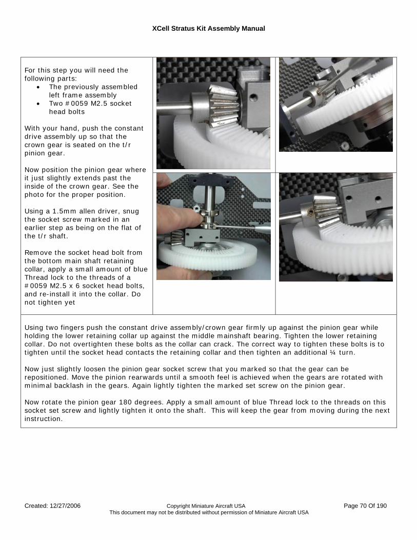
For this step you will need the following parts:
• The previously assembled left frame assembly
• Two #0059 M2.5 socket head bolts
With your hand, push the constant drive assembly up so that the crown gear is seated on the t/r pinion gear. Now position the pinion gear where it just slightly extends past the inside of the crown gear. See the photo for the proper position. Using a 1.5mm allen driver, snug the socket screw marked in an earlier step as being on the flat of the t/r shaft. Remove the socket head bolt from the bottom main shaft retaining collar, apply a small amount of blue Thread lock to the threads of a #0059 M2.5 x 6 socket head bolts, and re-install it into the collar. Do not tighten yet
Using two fingers push the constant drive assembly/crown gear firmly up against the pinion gear while holding the lower retaining collar up against the middle mainshaft bearing. Tighten the lower retaining collar. Do not overtighten these bolts as the collar can crack. The correct way to tighten these bolts is to tighten until the socket head contacts the retaining collar and then tighten an additional ¼ turn. Now just slightly loosen the pinion gear socket screw that you marked so that the gear can be repositioned. Move the pinion rearwards until a smooth feel is achieved when the gears are rotated with minimal backlash in the gears. Again lightly tighten the marked set screw on the pinion gear. Now rotate the pinion gear 180 degrees. Apply a small amount of blue Thread lock to the threads on this socket set screw and lightly tighten it onto the shaft. This will keep the gear from moving during the next instruction.
XCell Stratus Kit Assembly Manual
Created: 12/27/2006 Copyright Miniature Aircraft USA Page 71 Of 190 This document may not be distributed without permission of Miniature Aircraft USA
Now rotate the pinion gear again and remove the socket set screw that is against the t/r shaft flat. Apply a small amount of blue Thread lock to the threads on this socket screw and reinstall it. Tighten against the flat on the t/r shaft. Now rotate the pinion a final time and fully tighten the remaining socket set screw The t/r input pinion gear is now properly positioned. Now using two fingers, push the upper retaining collar up against the bottom of the upper mainshaft bearing. Repeat the tightening process previously outlined for the lower mainshaft retainer collar If you observe the retaining collars, there is a split where the collar tightens on the shaft. If after tightening, there is no gap in the collar, then the collar has been over tightened and has broken. If this is the case, the collar will need to be replaced as it will not hold the mainshaft properly. There should be a slight gap in the retainer split only.
For this step you will need the following parts:
• Left Upper ratio plate • Two #0060-1 M3 x 6mm bolts
You need the left ratio plate from Bag 2 for the particular engine and gear ratio kit you have selected. There are two sets of plates, an upper and lower. The plates are labeled as left and right sides.
Select the left upper clutch plate and two #0060-1 M3 x 6mm socket head bolts. Position the plate on the left frame as shown and using a small amount of blue Thread lock on the threads, thread the bolts into the PEM mounting nuts in the frame half. Tighten both bolts firmly. Make sure you install the marked left plate on the correct side.
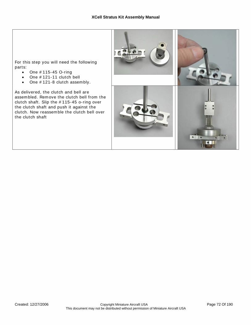
XCell Stratus Kit Assembly Manual
Created: 12/27/2006 Copyright Miniature Aircraft USA Page 72 Of 190 This document may not be distributed without permission of Miniature Aircraft USA
For this step you will need the following parts:
• One #115-45 O-ring • One #121-11 clutch bell • One #121-8 clutch assembly.
As delivered, the clutch and bell are assembled. Remove the clutch bell from the clutch shaft. Slip the #115-45 o-ring over the clutch shaft and push it against the clutch. Now reassemble the clutch bell over the clutch shaft
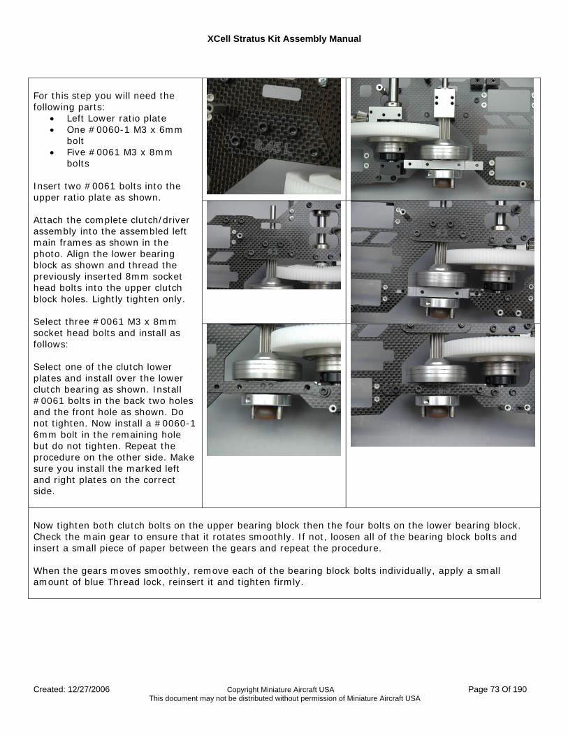
XCell Stratus Kit Assembly Manual
Created: 12/27/2006 Copyright Miniature Aircraft USA Page 73 Of 190 This document may not be distributed without permission of Miniature Aircraft USA
For this step you will need the following parts:
• Left Lower ratio plate • One #0060-1 M3 x 6mm
bolt • Five #0061 M3 x 8mm
bolts Insert two #0061 bolts into the upper ratio plate as shown. Attach the complete clutch/driver assembly into the assembled left main frames as shown in the photo. Align the lower bearing block as shown and thread the previously inserted 8mm socket head bolts into the upper clutch block holes. Lightly tighten only. Select three #0061 M3 x 8mm socket head bolts and install as follows: Select one of the clutch lower plates and install over the lower clutch bearing as shown. Install #0061 bolts in the back two holes and the front hole as shown. Do not tighten. Now install a #0060-1 6mm bolt in the remaining hole but do not tighten. Repeat the procedure on the other side. Make sure you install the marked left and right plates on the correct side.
Now tighten both clutch bolts on the upper bearing block then the four bolts on the lower bearing block. Check the main gear to ensure that it rotates smoothly. If not, loosen all of the bearing block bolts and insert a small piece of paper between the gears and repeat the procedure. When the gears moves smoothly, remove each of the bearing block bolts individually, apply a small amount of blue Thread lock, reinsert it and tighten firmly.
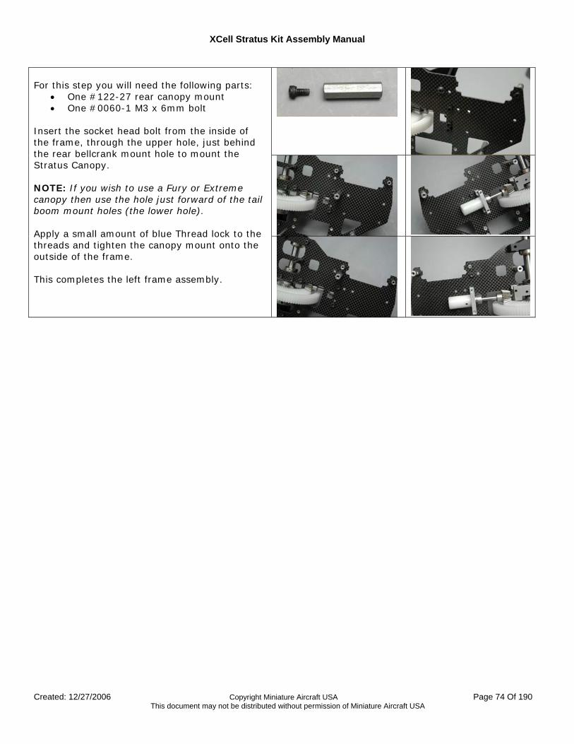
XCell Stratus Kit Assembly Manual
Created: 12/27/2006 Copyright Miniature Aircraft USA Page 74 Of 190 This document may not be distributed without permission of Miniature Aircraft USA
For this step you will need the following parts:
• One #122-27 rear canopy mount • One #0060-1 M3 x 6mm bolt
Insert the socket head bolt from the inside of the frame, through the upper hole, just behind the rear bellcrank mount hole to mount the Stratus Canopy. NOTE: If you wish to use a Fury or Extreme canopy then use the hole just forward of the tail boom mount holes (the lower hole). Apply a small amount of blue Thread lock to the threads and tighten the canopy mount onto the outside of the frame. This completes the left frame assembly.
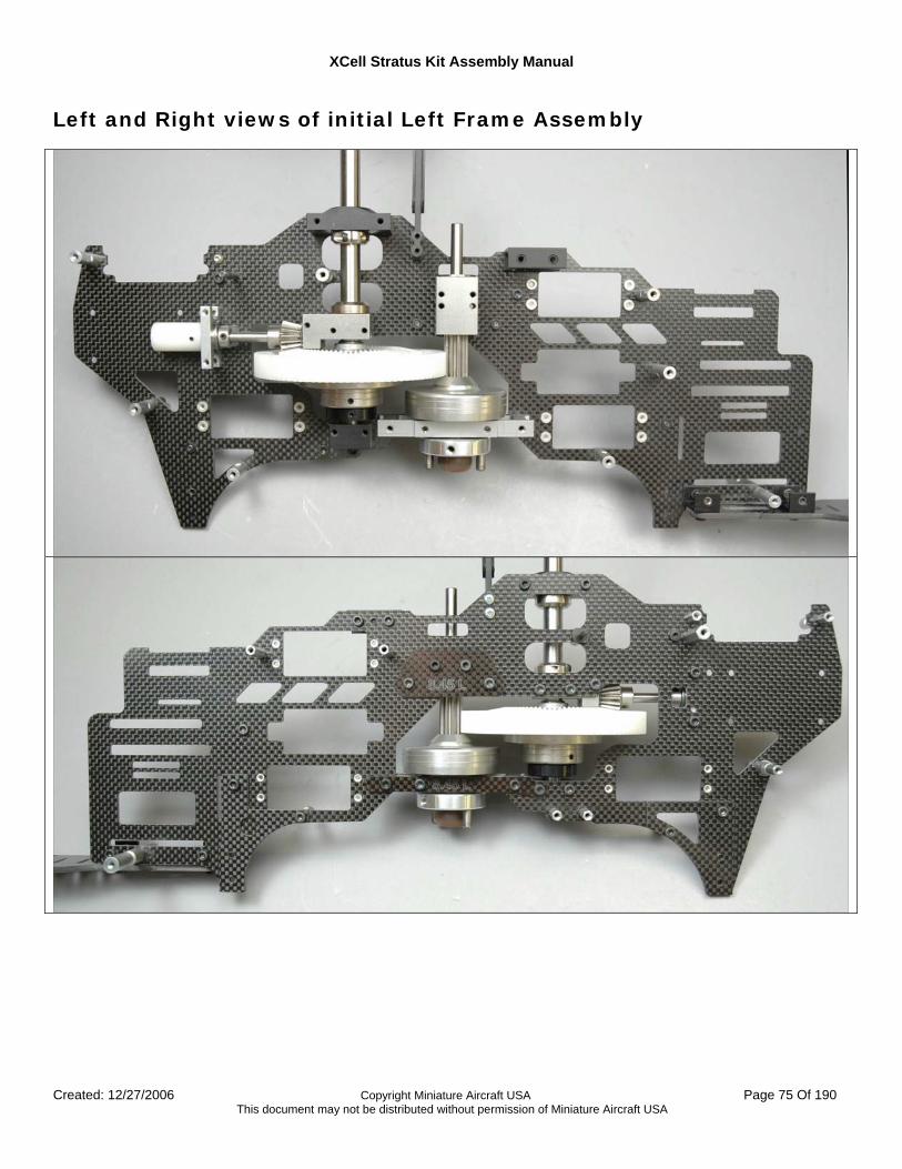
XCell Stratus Kit Assembly Manual
Created: 12/27/2006 Copyright Miniature Aircraft USA Page 75 Of 190 This document may not be distributed without permission of Miniature Aircraft USA
Left and Right views of initial Left Frame Assembly
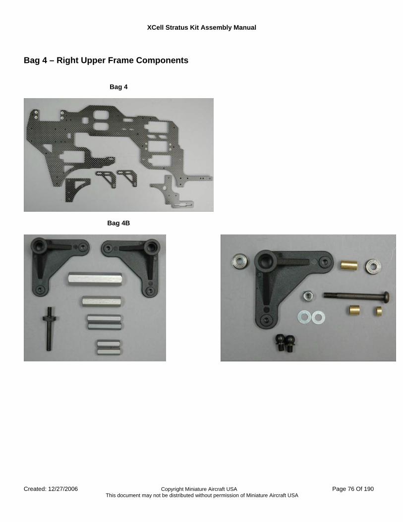
XCell Stratus Kit Assembly Manual
Created: 12/27/2006 Copyright Miniature Aircraft USA Page 76 Of 190 This document may not be distributed without permission of Miniature Aircraft USA
Bag 4 – Right Upper Frame Components
Bag 4
Bag 4B
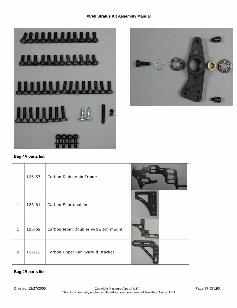
XCell Stratus Kit Assembly Manual
Created: 12/27/2006 Copyright Miniature Aircraft USA Page 77 Of 190 This document may not be distributed without permission of Miniature Aircraft USA
Bag 4A parts list
1 126-57 Carbon Right Main Frame
1 126-61 Carbon Rear doubler
1 126-62 Carbon Front Doubler w/Switch mount
2 126-72 Carbon Upper Fan Shroud Bracket
Bag 4B parts list
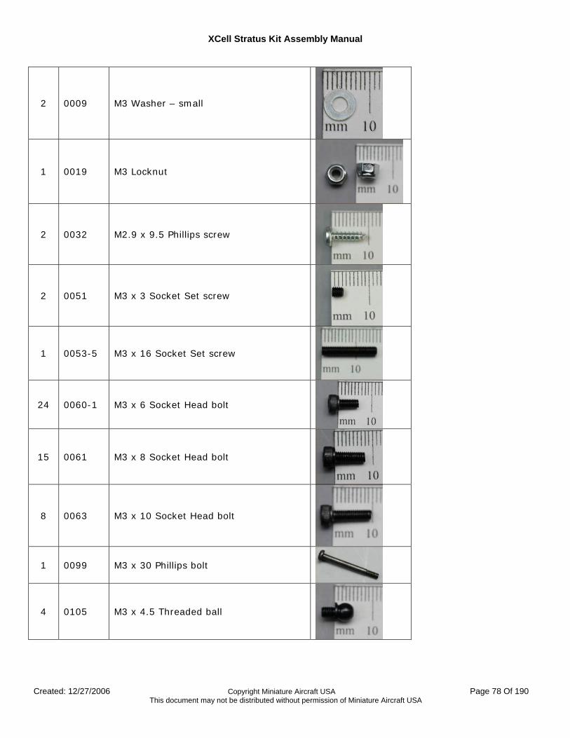
XCell Stratus Kit Assembly Manual
Created: 12/27/2006 Copyright Miniature Aircraft USA Page 78 Of 190 This document may not be distributed without permission of Miniature Aircraft USA
2 0009 M3 Washer – small
1 0019 M3 Locknut
2 0032 M2.9 x 9.5 Phillips screw
2 0051 M3 x 3 Socket Set screw
1 0053-5 M3 x 16 Socket Set screw
24 0060-1 M3 x 6 Socket Head bolt
15 0061 M3 x 8 Socket Head bolt
8 0063 M3 x 10 Socket Head bolt
1 0099 M3 x 30 Phillips bolt
4 0105 M3 x 4.5 Threaded ball
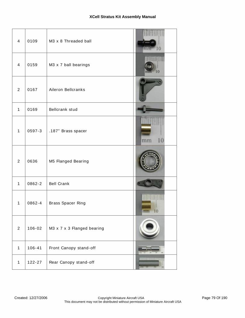
XCell Stratus Kit Assembly Manual
Created: 12/27/2006 Copyright Miniature Aircraft USA Page 79 Of 190 This document may not be distributed without permission of Miniature Aircraft USA
4 0109 M3 x 8 Threaded ball
4 0159 M3 x 7 ball bearings
2 0167 Aileron Bellcranks
1 0169 Bellcrank stud
1 0597-3 .187” Brass spacer
2 0636 M5 Flanged Bearing
1 0862-2 Bell Crank
1 0862-4 Brass Spacer Ring
2 106-02 M3 x 7 x 3 Flanged bearing
1 106-41 Front Canopy stand-off
1 122-27 Rear Canopy stand-off
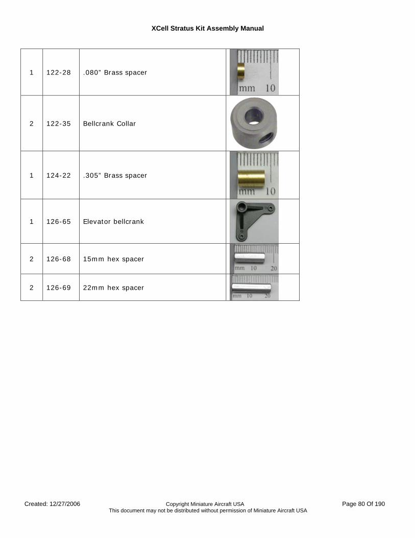
XCell Stratus Kit Assembly Manual
Created: 12/27/2006 Copyright Miniature Aircraft USA Page 80 Of 190 This document may not be distributed without permission of Miniature Aircraft USA
1 122-28 .080” Brass spacer
2 122-35 Bellcrank Collar
1 124-22 .305” Brass spacer
1 126-65 Elevator bellcrank
2 126-68 15mm hex spacer
2 126-69 22mm hex spacer
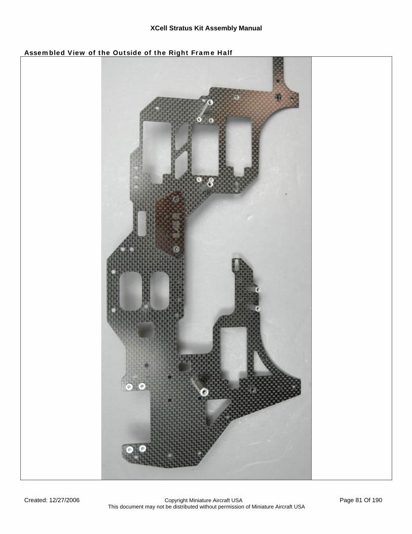
XCell Stratus Kit Assembly Manual
Created: 12/27/2006 Copyright Miniature Aircraft USA Page 81 Of 190 This document may not be distributed without permission of Miniature Aircraft USA
Assembled View of the Outside of the Right Frame Half
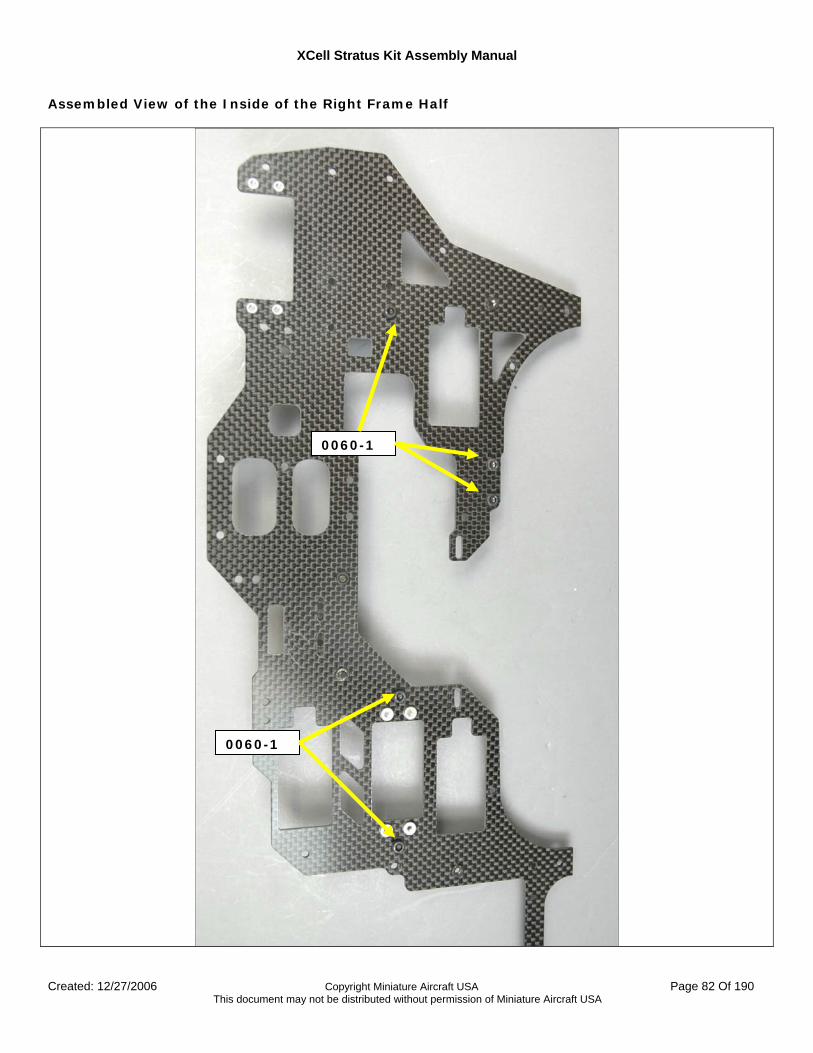
XCell Stratus Kit Assembly Manual
Created: 12/27/2006 Copyright Miniature Aircraft USA Page 82 Of 190 This document may not be distributed without permission of Miniature Aircraft USA
Assembled View of the Inside of the Right Frame Half
0060-1
0060-1
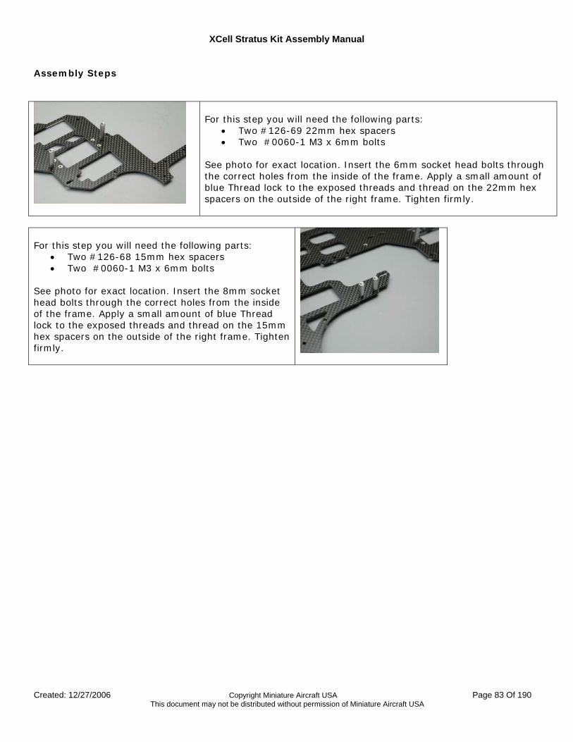
XCell Stratus Kit Assembly Manual
Created: 12/27/2006 Copyright Miniature Aircraft USA Page 83 Of 190 This document may not be distributed without permission of Miniature Aircraft USA
Assembly Steps
For this step you will need the following parts:
• Two #126-69 22mm hex spacers • Two #0060-1 M3 x 6mm bolts
See photo for exact location. Insert the 6mm socket head bolts through the correct holes from the inside of the frame. Apply a small amount of blue Thread lock to the exposed threads and thread on the 22mm hex spacers on the outside of the right frame. Tighten firmly.
For this step you will need the following parts:
• Two #126-68 15mm hex spacers • Two #0060-1 M3 x 6mm bolts
See photo for exact location. Insert the 8mm socket head bolts through the correct holes from the inside of the frame. Apply a small amount of blue Thread lock to the exposed threads and thread on the 15mm hex spacers on the outside of the right frame. Tighten firmly.
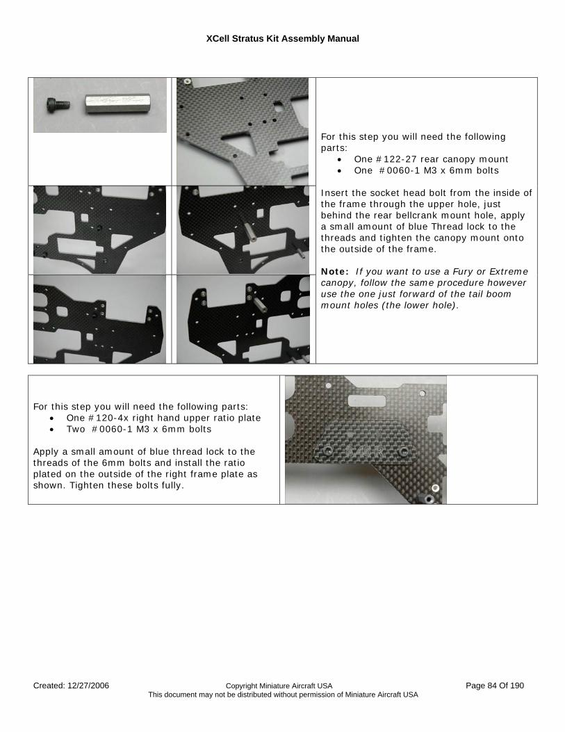
XCell Stratus Kit Assembly Manual
Created: 12/27/2006 Copyright Miniature Aircraft USA Page 84 Of 190 This document may not be distributed without permission of Miniature Aircraft USA
For this step you will need the following parts:
• One #122-27 rear canopy mount • One #0060-1 M3 x 6mm bolts
Insert the socket head bolt from the inside of the frame through the upper hole, just behind the rear bellcrank mount hole, apply a small amount of blue Thread lock to the threads and tighten the canopy mount onto the outside of the frame. Note: If you want to use a Fury or Extreme canopy, follow the same procedure however use the one just forward of the tail boom mount holes (the lower hole).
For this step you will need the following parts:
• One #120-4x right hand upper ratio plate • Two #0060-1 M3 x 6mm bolts
Apply a small amount of blue thread lock to the threads of the 6mm bolts and install the ratio plated on the outside of the right frame plate as shown. Tighten these bolts fully.
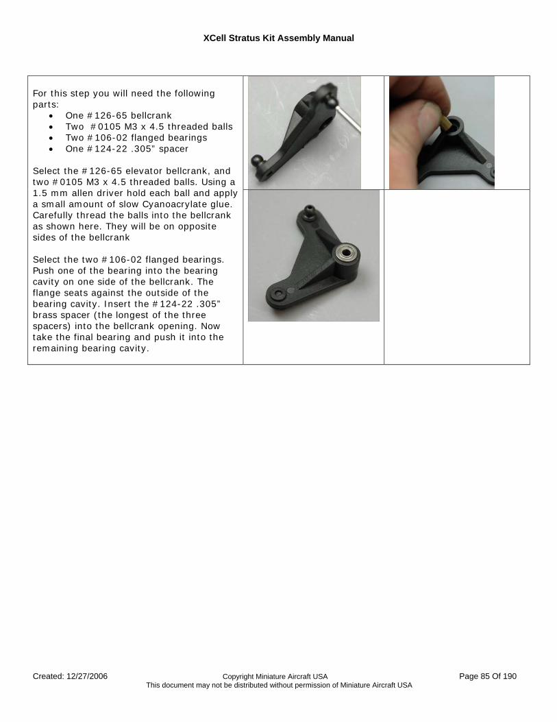
XCell Stratus Kit Assembly Manual
Created: 12/27/2006 Copyright Miniature Aircraft USA Page 85 Of 190 This document may not be distributed without permission of Miniature Aircraft USA
For this step you will need the following parts:
• One #126-65 bellcrank • Two #0105 M3 x 4.5 threaded balls • Two #106-02 flanged bearings • One #124-22 .305” spacer
Select the #126-65 elevator bellcrank, and two #0105 M3 x 4.5 threaded balls. Using a 1.5 mm allen driver hold each ball and apply a small amount of slow Cyanoacrylate glue. Carefully thread the balls into the bellcrank as shown here. They will be on opposite sides of the bellcrank Select the two #106-02 flanged bearings. Push one of the bearing into the bearing cavity on one side of the bellcrank. The flange seats against the outside of the bearing cavity. Insert the #124-22 .305” brass spacer (the longest of the three spacers) into the bellcrank opening. Now take the final bearing and push it into the remaining bearing cavity.
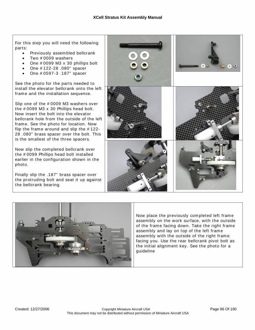
XCell Stratus Kit Assembly Manual
Created: 12/27/2006 Copyright Miniature Aircraft USA Page 86 Of 190 This document may not be distributed without permission of Miniature Aircraft USA
For this step you will need the following parts:
• Previously assembled bellcrank • Two #0009 washers • One #0099 M3 x 30 phillips bolt • One #122-28 .080” spacer • One #0597-3 .187” spacer
See the photo for the parts needed to install the elevator bellcrank onto the left frame and the installation sequence. Slip one of the #0009 M3 washers over the #0099 M3 x 30 Phillips head bolt. Now insert the bolt into the elevator bellcrank hole from the outside of the left frame. See the photo for location. Now flip the frame around and slip the #122-28 .080” brass spacer over the bolt. This is the smallest of the three spacers. Now slip the completed bellcrank over the #0099 Phillips head bolt installed earlier in the configuration shown in the photo. Finally slip the .187” brass spacer over the protruding bolt and seat it up against the bellcrank bearing.
Now place the previously completed left frame assembly on the work surface, with the outside of the frame facing down. Take the right frame assembly and lay on top of the left frame assembly with the outside of the right frame facing you. Use the rear bellcrank pivot bolt as the initial alignment key. See the photo for a guideline
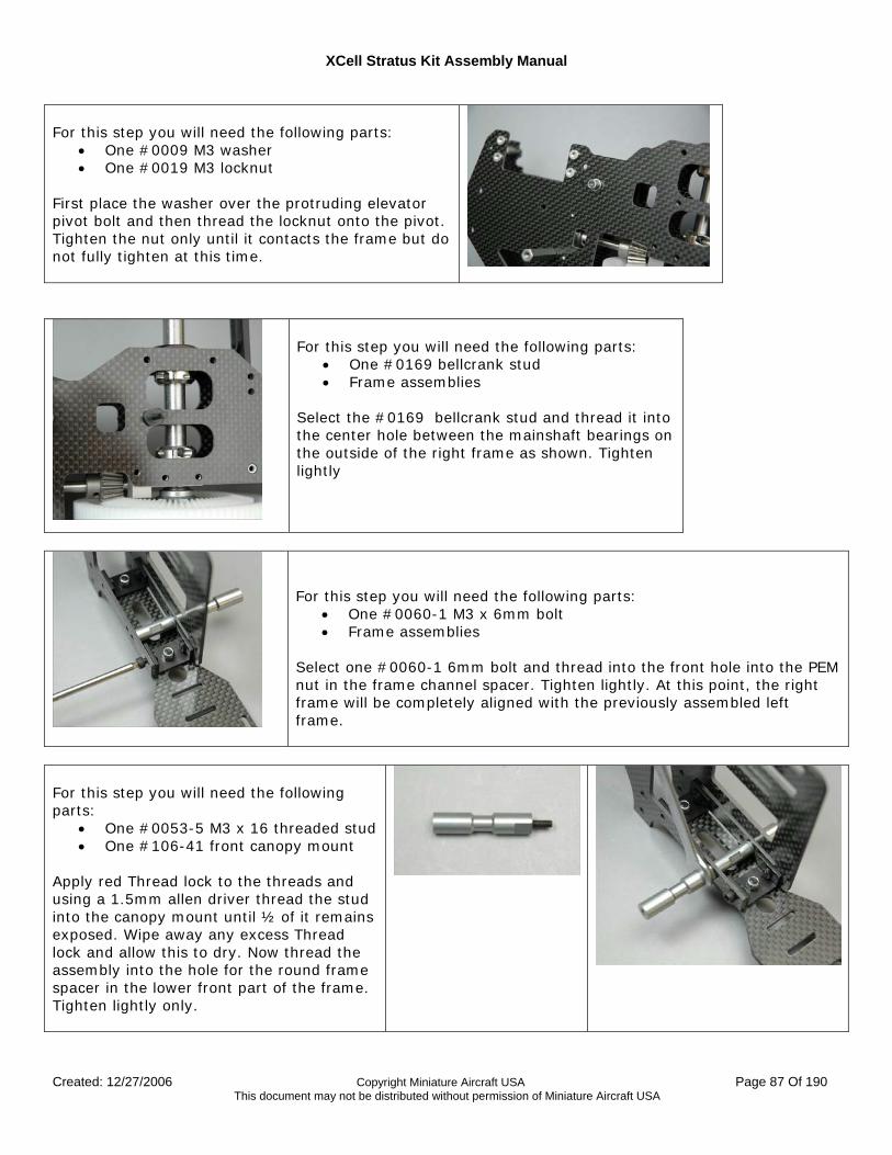
XCell Stratus Kit Assembly Manual
Created: 12/27/2006 Copyright Miniature Aircraft USA Page 87 Of 190 This document may not be distributed without permission of Miniature Aircraft USA
For this step you will need the following parts:
• One #0009 M3 washer • One #0019 M3 locknut
First place the washer over the protruding elevator pivot bolt and then thread the locknut onto the pivot. Tighten the nut only until it contacts the frame but do not fully tighten at this time.
For this step you will need the following parts:
• One #0169 bellcrank stud • Frame assemblies
Select the #0169 bellcrank stud and thread it into the center hole between the mainshaft bearings on the outside of the right frame as shown. Tighten lightly
For this step you will need the following parts:
• One #0060-1 M3 x 6mm bolt • Frame assemblies
Select one #0060-1 6mm bolt and thread into the front hole into the PEM nut in the frame channel spacer. Tighten lightly. At this point, the right frame will be completely aligned with the previously assembled left frame.
For this step you will need the following parts:
• One #0053-5 M3 x 16 threaded stud • One #106-41 front canopy mount
Apply red Thread lock to the threads and using a 1.5mm allen driver thread the stud into the canopy mount until ½ of it remains exposed. Wipe away any excess Thread lock and allow this to dry. Now thread the assembly into the hole for the round frame spacer in the lower front part of the frame. Tighten lightly only.
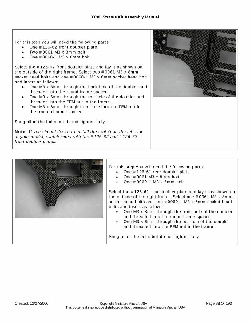
XCell Stratus Kit Assembly Manual
Created: 12/27/2006 Copyright Miniature Aircraft USA Page 88 Of 190 This document may not be distributed without permission of Miniature Aircraft USA
For this step you will need the following parts:
• One #126-62 front doubler plate • Two #0061 M3 x 8mm bolt • One #0060-1 M3 x 6mm bolt
Select the #126-62 front doubler plate and lay it as shown on the outside of the right frame. Select two #0061 M3 x 8mm socket head bolts and one #0060-1 M3 x 6mm socket head bolt and insert as follows:
• One M3 x 8mm through the back hole of the doubler and threaded into the round frame spacer.
• One M3 x 6mm through the top hole of the doubler and threaded into the PEM nut in the frame
• One M3 x 8mm through front hole into the PEM nut in the frame channel spacer
Snug all of the bolts but do not tighten fully Note: If you should desire to install the switch on the left side of your model, switch sides with the #126-62 and #126-63 front doubler plates.
For this step you will need the following parts:
• One #126-61 rear doubler plate • One #0061 M3 x 8mm bolt • One #0060-1 M3 x 6mm bolt
Select the #126-61 rear doubler plate and lay it as shown on the outside of the right frame. Select one #0061 M3 x 8mm socket head bolts and one #0060-1 M3 x 6mm socket head bolts and insert as follows:
• One M3 x 8mm through the front hole of the doubler and threaded into the round frame spacer.
• One M3 x 6mm through the top hole of the doubler and threaded into the PEM nut in the frame
Snug all of the bolts but do not tighten fully
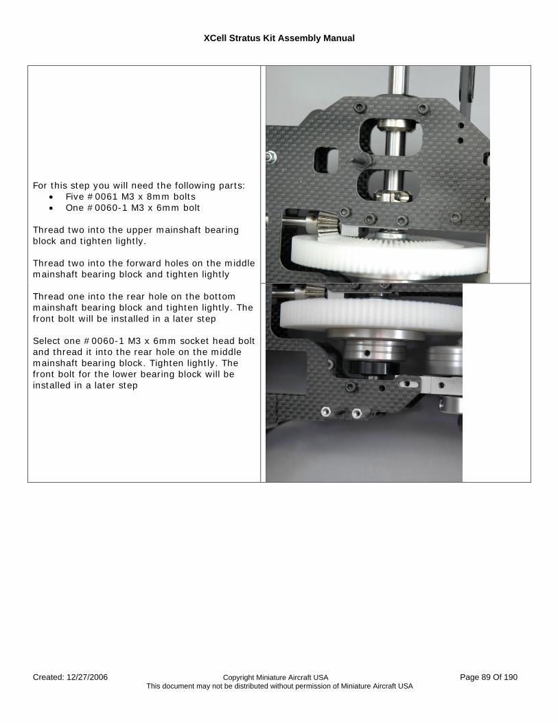
XCell Stratus Kit Assembly Manual
Created: 12/27/2006 Copyright Miniature Aircraft USA Page 89 Of 190 This document may not be distributed without permission of Miniature Aircraft USA
For this step you will need the following parts:
• Five #0061 M3 x 8mm bolts • One #0060-1 M3 x 6mm bolt
Thread two into the upper mainshaft bearing block and tighten lightly. Thread two into the forward holes on the middle mainshaft bearing block and tighten lightly Thread one into the rear hole on the bottom mainshaft bearing block and tighten lightly. The front bolt will be installed in a later step Select one #0060-1 M3 x 6mm socket head bolt and thread it into the rear hole on the middle mainshaft bearing block. Tighten lightly. The front bolt for the lower bearing block will be installed in a later step
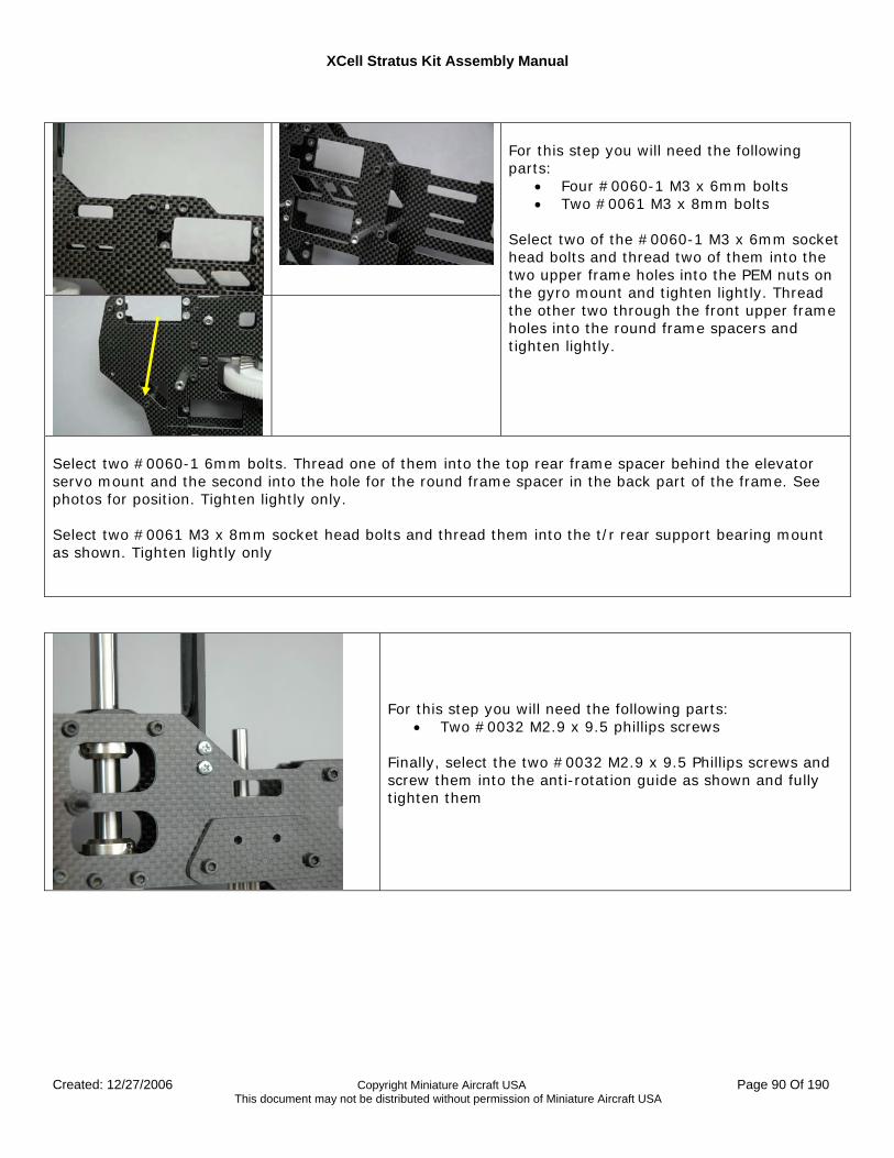
XCell Stratus Kit Assembly Manual
Created: 12/27/2006 Copyright Miniature Aircraft USA Page 90 Of 190 This document may not be distributed without permission of Miniature Aircraft USA
For this step you will need the following parts:
• Four #0060-1 M3 x 6mm bolts • Two #0061 M3 x 8mm bolts
Select two of the #0060-1 M3 x 6mm socket head bolts and thread two of them into the two upper frame holes into the PEM nuts on the gyro mount and tighten lightly. Thread the other two through the front upper frame holes into the round frame spacers and tighten lightly.
Select two #0060-1 6mm bolts. Thread one of them into the top rear frame spacer behind the elevator servo mount and the second into the hole for the round frame spacer in the back part of the frame. See photos for position. Tighten lightly only. Select two #0061 M3 x 8mm socket head bolts and thread them into the t/r rear support bearing mount as shown. Tighten lightly only
For this step you will need the following parts: • Two #0032 M2.9 x 9.5 phillips screws
Finally, select the two #0032 M2.9 x 9.5 Phillips screws and screw them into the anti-rotation guide as shown and fully tighten them
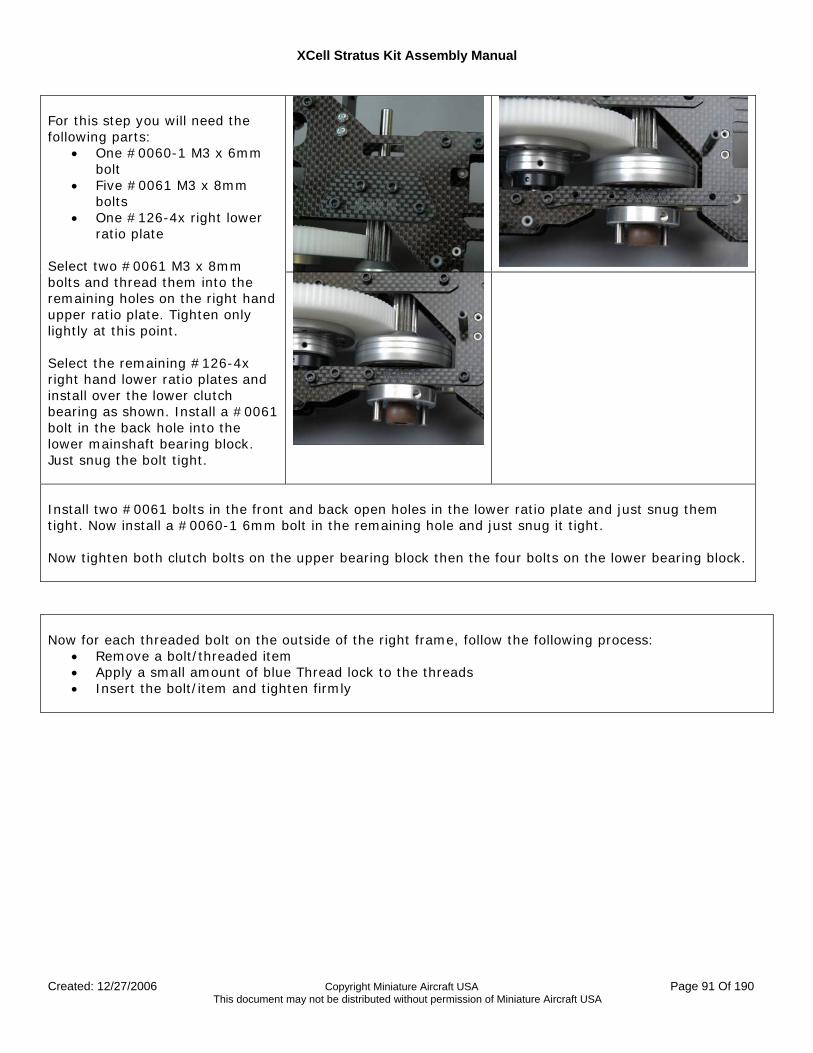
XCell Stratus Kit Assembly Manual
Created: 12/27/2006 Copyright Miniature Aircraft USA Page 91 Of 190 This document may not be distributed without permission of Miniature Aircraft USA
For this step you will need the following parts:
• One #0060-1 M3 x 6mm bolt
• Five #0061 M3 x 8mm bolts
• One #126-4x right lower ratio plate
Select two #0061 M3 x 8mm bolts and thread them into the remaining holes on the right hand upper ratio plate. Tighten only lightly at this point. Select the remaining #126-4x right hand lower ratio plates and install over the lower clutch bearing as shown. Install a #0061 bolt in the back hole into the lower mainshaft bearing block. Just snug the bolt tight.
Install two #0061 bolts in the front and back open holes in the lower ratio plate and just snug them tight. Now install a #0060-1 6mm bolt in the remaining hole and just snug it tight. Now tighten both clutch bolts on the upper bearing block then the four bolts on the lower bearing block. Now for each threaded bolt on the outside of the right frame, follow the following process:
• Remove a bolt/threaded item • Apply a small amount of blue Thread lock to the threads • Insert the bolt/item and tighten firmly
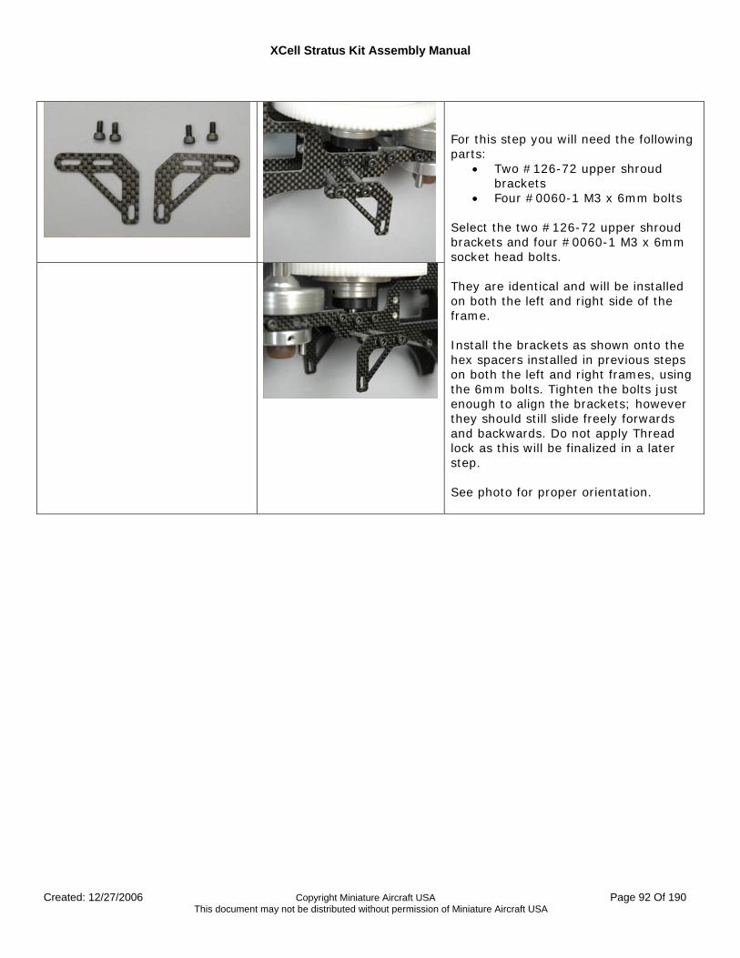
XCell Stratus Kit Assembly Manual
Created: 12/27/2006 Copyright Miniature Aircraft USA Page 92 Of 190 This document may not be distributed without permission of Miniature Aircraft USA
For this step you will need the following parts:
• Two #126-72 upper shroud brackets
• Four #0060-1 M3 x 6mm bolts Select the two #126-72 upper shroud brackets and four #0060-1 M3 x 6mm socket head bolts. They are identical and will be installed on both the left and right side of the frame. Install the brackets as shown onto the hex spacers installed in previous steps on both the left and right frames, using the 6mm bolts. Tighten the bolts just enough to align the brackets; however they should still slide freely forwards and backwards. Do not apply Thread lock as this will be finalized in a later step. See photo for proper orientation.
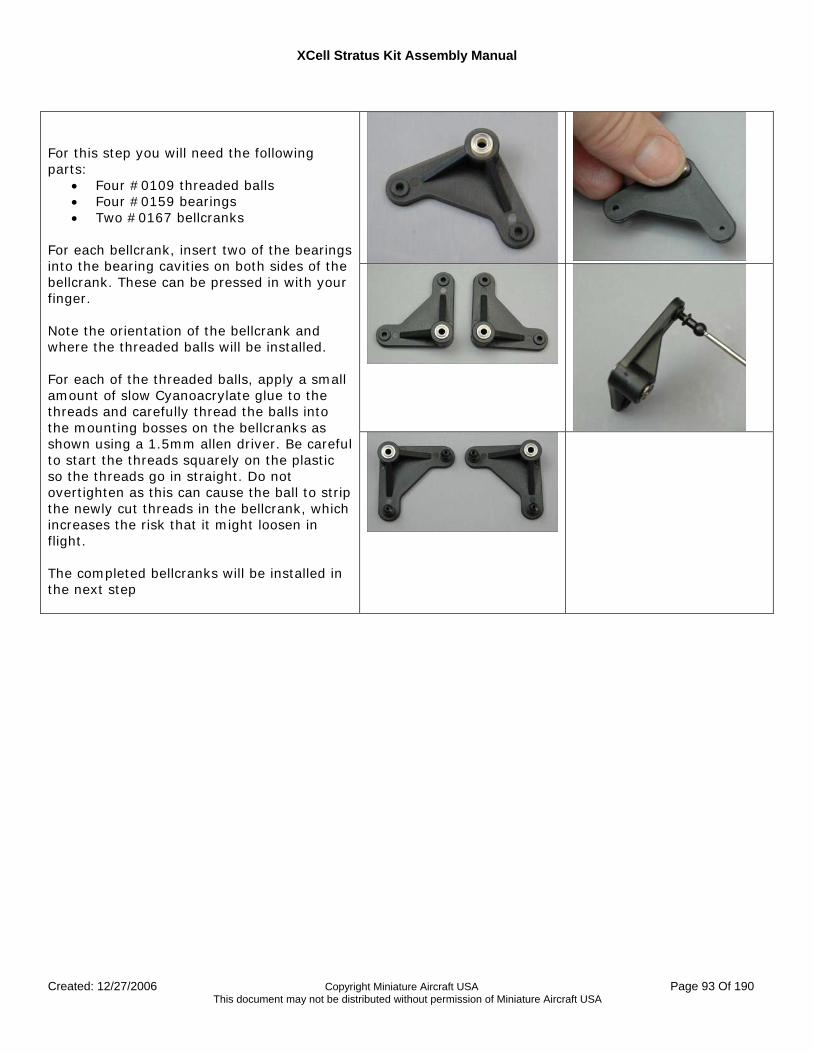
XCell Stratus Kit Assembly Manual
Created: 12/27/2006 Copyright Miniature Aircraft USA Page 93 Of 190 This document may not be distributed without permission of Miniature Aircraft USA
For this step you will need the following parts:
• Four #0109 threaded balls • Four #0159 bearings • Two #0167 bellcranks
For each bellcrank, insert two of the bearings into the bearing cavities on both sides of the bellcrank. These can be pressed in with your finger. Note the orientation of the bellcrank and where the threaded balls will be installed. For each of the threaded balls, apply a small amount of slow Cyanoacrylate glue to the threads and carefully thread the balls into the mounting bosses on the bellcranks as shown using a 1.5mm allen driver. Be careful to start the threads squarely on the plastic so the threads go in straight. Do not overtighten as this can cause the ball to strip the newly cut threads in the bellcrank, which increases the risk that it might loosen in flight. The completed bellcranks will be installed in the next step
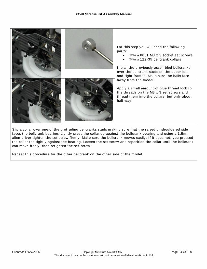
XCell Stratus Kit Assembly Manual
Created: 12/27/2006 Copyright Miniature Aircraft USA Page 94 Of 190 This document may not be distributed without permission of Miniature Aircraft USA
For this step you will need the following parts:
• Two #0051 M3 x 3 socket set screws • Two #122-35 bellcrank collars
Install the previously assembled bellcranks over the bellcrank studs on the upper left and right frames. Make sure the balls face away from the model. Apply a small amount of blue thread lock to the threads on the M3 x 3 set screws and thread them into the collars, but only about half way.
Slip a collar over one of the protruding bellcranks studs making sure that the raised or shouldered side faces the bellcrank bearing. Lightly press the collar up against the bellcrank bearing and using a 1.5mm allen driver tighten the set screw firmly. Make sure the bellcrank moves easily. If it does not, you pressed the collar too tightly against the bearing. Loosen the set screw and reposition the collar until the bellcrank can move freely, then retighten the set screw. Repeat this procedure for the other bellcrank on the other side of the model.
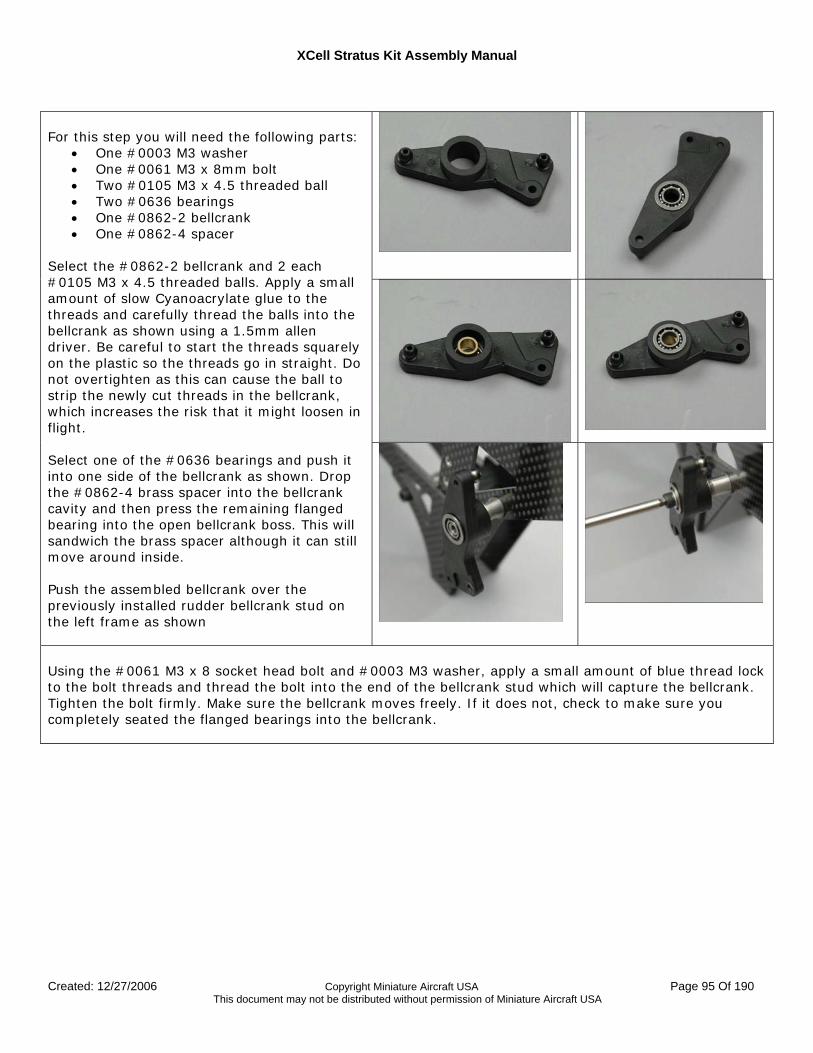
XCell Stratus Kit Assembly Manual
Created: 12/27/2006 Copyright Miniature Aircraft USA Page 95 Of 190 This document may not be distributed without permission of Miniature Aircraft USA
For this step you will need the following parts:
• One #0003 M3 washer • One #0061 M3 x 8mm bolt • Two #0105 M3 x 4.5 threaded ball • Two #0636 bearings • One #0862-2 bellcrank • One #0862-4 spacer
Select the #0862-2 bellcrank and 2 each #0105 M3 x 4.5 threaded balls. Apply a small amount of slow Cyanoacrylate glue to the threads and carefully thread the balls into the bellcrank as shown using a 1.5mm allen driver. Be careful to start the threads squarely on the plastic so the threads go in straight. Do not overtighten as this can cause the ball to strip the newly cut threads in the bellcrank, which increases the risk that it might loosen in flight. Select one of the #0636 bearings and push it into one side of the bellcrank as shown. Drop the #0862-4 brass spacer into the bellcrank cavity and then press the remaining flanged bearing into the open bellcrank boss. This will sandwich the brass spacer although it can still move around inside. Push the assembled bellcrank over the previously installed rudder bellcrank stud on the left frame as shown
Using the #0061 M3 x 8 socket head bolt and #0003 M3 washer, apply a small amount of blue thread lock to the bolt threads and thread the bolt into the end of the bellcrank stud which will capture the bellcrank. Tighten the bolt firmly. Make sure the bellcrank moves freely. If it does not, check to make sure you completely seated the flanged bearings into the bellcrank.
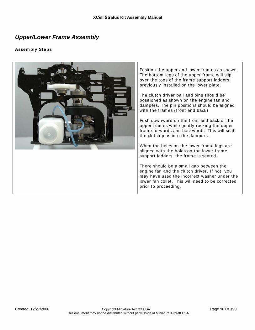
XCell Stratus Kit Assembly Manual
Created: 12/27/2006 Copyright Miniature Aircraft USA Page 96 Of 190 This document may not be distributed without permission of Miniature Aircraft USA
Upper/Lower Frame Assembly Assembly Steps
Position the upper and lower frames as shown. The bottom legs of the upper frame will slip over the tops of the frame support ladders previously installed on the lower plate. The clutch driver ball and pins should be positioned as shown on the engine fan and dampers. The pin positions should be aligned with the frames (front and back) Push downward on the front and back of the upper frames while gently rocking the upper frame forwards and backwards. This will seat the clutch pins into the dampers. When the holes on the lower frame legs are aligned with the holes on the lower frame support ladders, the frame is seated. There should be a small gap between the engine fan and the clutch driver. If not, you may have used the incorrect washer under the lower fan collet. This will need to be corrected prior to proceeding.
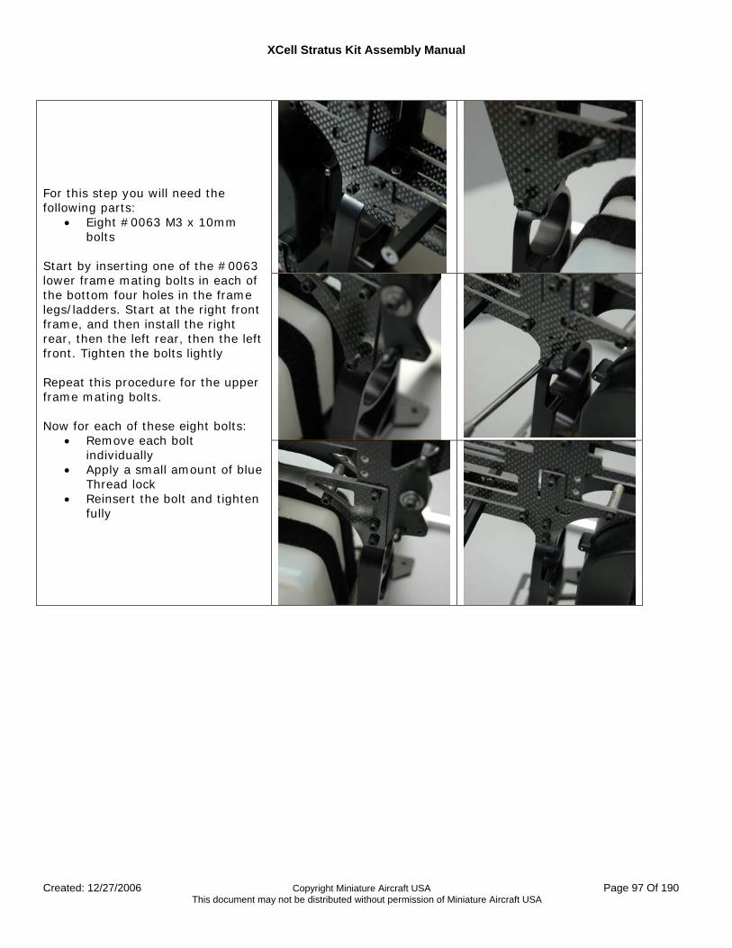
XCell Stratus Kit Assembly Manual
Created: 12/27/2006 Copyright Miniature Aircraft USA Page 97 Of 190 This document may not be distributed without permission of Miniature Aircraft USA
For this step you will need the following parts:
• Eight #0063 M3 x 10mm bolts
Start by inserting one of the #0063 lower frame mating bolts in each of the bottom four holes in the frame legs/ladders. Start at the right front frame, and then install the right rear, then the left rear, then the left front. Tighten the bolts lightly Repeat this procedure for the upper frame mating bolts. Now for each of these eight bolts:
• Remove each bolt individually
• Apply a small amount of blue Thread lock
• Reinsert the bolt and tighten fully
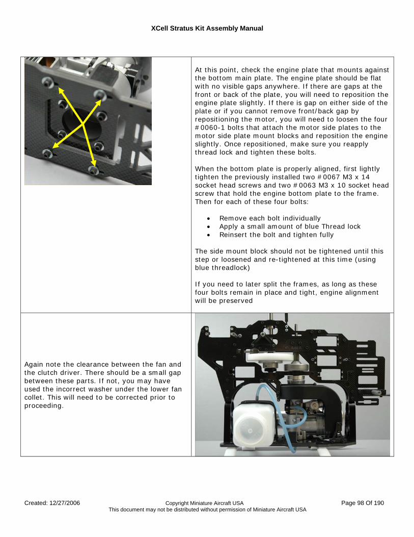
XCell Stratus Kit Assembly Manual
Created: 12/27/2006 Copyright Miniature Aircraft USA Page 98 Of 190 This document may not be distributed without permission of Miniature Aircraft USA
At this point, check the engine plate that mounts against the bottom main plate. The engine plate should be flat with no visible gaps anywhere. If there are gaps at the front or back of the plate, you will need to reposition the engine plate slightly. If there is gap on either side of the plate or if you cannot remove front/back gap by repositioning the motor, you will need to loosen the four #0060-1 bolts that attach the motor side plates to the motor side plate mount blocks and reposition the engine slightly. Once repositioned, make sure you reapply thread lock and tighten these bolts. When the bottom plate is properly aligned, first lightly tighten the previously installed two #0067 M3 x 14 socket head screws and two #0063 M3 x 10 socket head screw that hold the engine bottom plate to the frame. Then for each of these four bolts:
• Remove each bolt individually • Apply a small amount of blue Thread lock • Reinsert the bolt and tighten fully
The side mount block should not be tightened until this step or loosened and re-tightened at this time (using blue threadlock) If you need to later split the frames, as long as these four bolts remain in place and tight, engine alignment will be preserved
Again note the clearance between the fan and the clutch driver. There should be a small gap between these parts. If not, you may have used the incorrect washer under the lower fan collet. This will need to be corrected prior to proceeding.
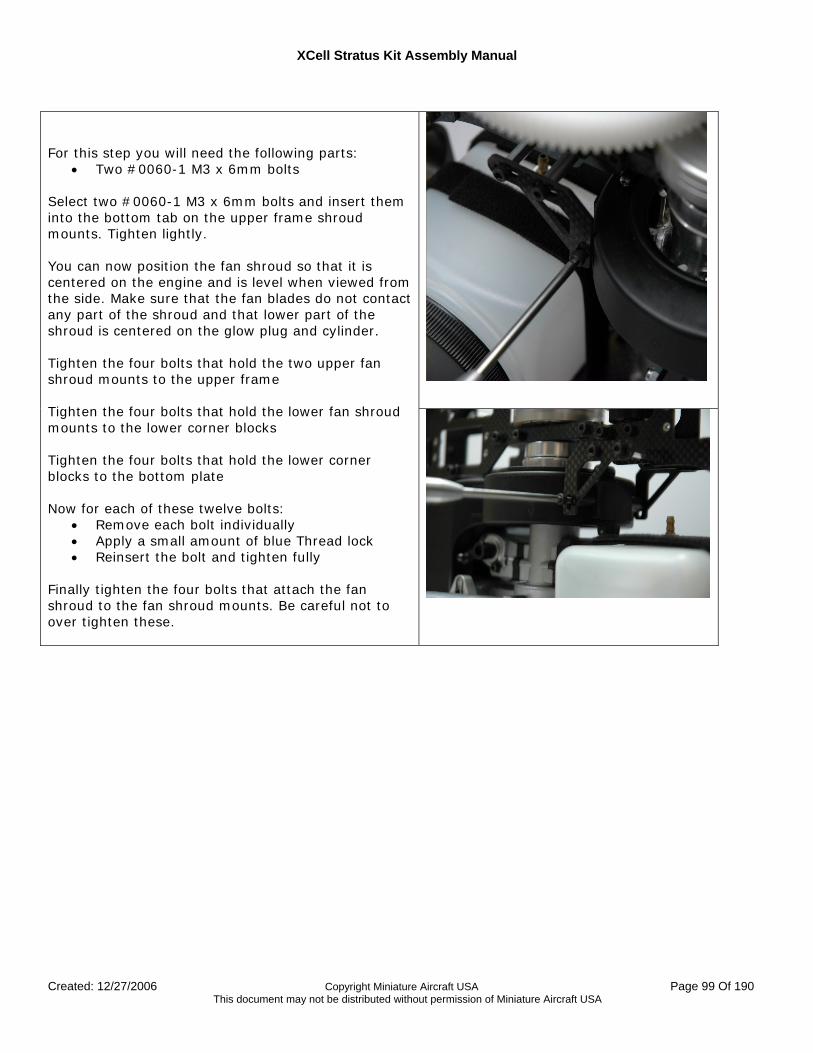
XCell Stratus Kit Assembly Manual
Created: 12/27/2006 Copyright Miniature Aircraft USA Page 99 Of 190 This document may not be distributed without permission of Miniature Aircraft USA
For this step you will need the following parts:
• Two #0060-1 M3 x 6mm bolts Select two #0060-1 M3 x 6mm bolts and insert them into the bottom tab on the upper frame shroud mounts. Tighten lightly. You can now position the fan shroud so that it is centered on the engine and is level when viewed from the side. Make sure that the fan blades do not contact any part of the shroud and that lower part of the shroud is centered on the glow plug and cylinder. Tighten the four bolts that hold the two upper fan shroud mounts to the upper frame Tighten the four bolts that hold the lower fan shroud mounts to the lower corner blocks Tighten the four bolts that hold the lower corner blocks to the bottom plate Now for each of these twelve bolts:
• Remove each bolt individually • Apply a small amount of blue Thread lock • Reinsert the bolt and tighten fully
Finally tighten the four bolts that attach the fan shroud to the fan shroud mounts. Be careful not to over tighten these.
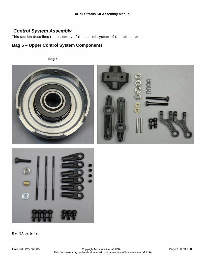
XCell Stratus Kit Assembly Manual
Created: 12/27/2006 Copyright Miniature Aircraft USA Page 100 Of 190 This document may not be distributed without permission of Miniature Aircraft USA
Control System Assembly This section describes the assembly of the control system of the helicopter
Bag 5 – Upper Control System Components
Bag 5
Bag 5A parts list
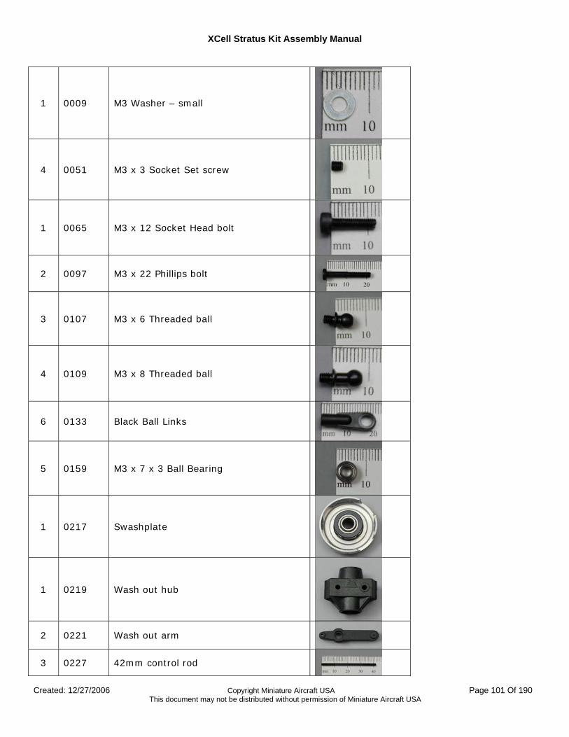
XCell Stratus Kit Assembly Manual
Created: 12/27/2006 Copyright Miniature Aircraft USA Page 101 Of 190 This document may not be distributed without permission of Miniature Aircraft USA
1 0009 M3 Washer – small
4 0051 M3 x 3 Socket Set screw
1 0065 M3 x 12 Socket Head bolt
2 0097 M3 x 22 Phillips bolt
3 0107 M3 x 6 Threaded ball
4 0109 M3 x 8 Threaded ball
6 0133 Black Ball Links
5 0159 M3 x 7 x 3 Ball Bearing
1 0217 Swashplate
1 0219 Wash out hub
2 0221 Wash out arm
3 0227 42mm control rod
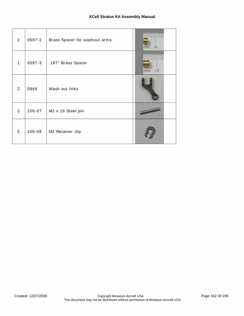
XCell Stratus Kit Assembly Manual
Created: 12/27/2006 Copyright Miniature Aircraft USA Page 102 Of 190 This document may not be distributed without permission of Miniature Aircraft USA
2 0597-2 Brass Spacer for washout arms
1 0597-3 .187” Brass Spacer
2 0869 Wash out links
2 106-07 M2 x 16 Steel pin
5 106-08 M2 Retainer clip
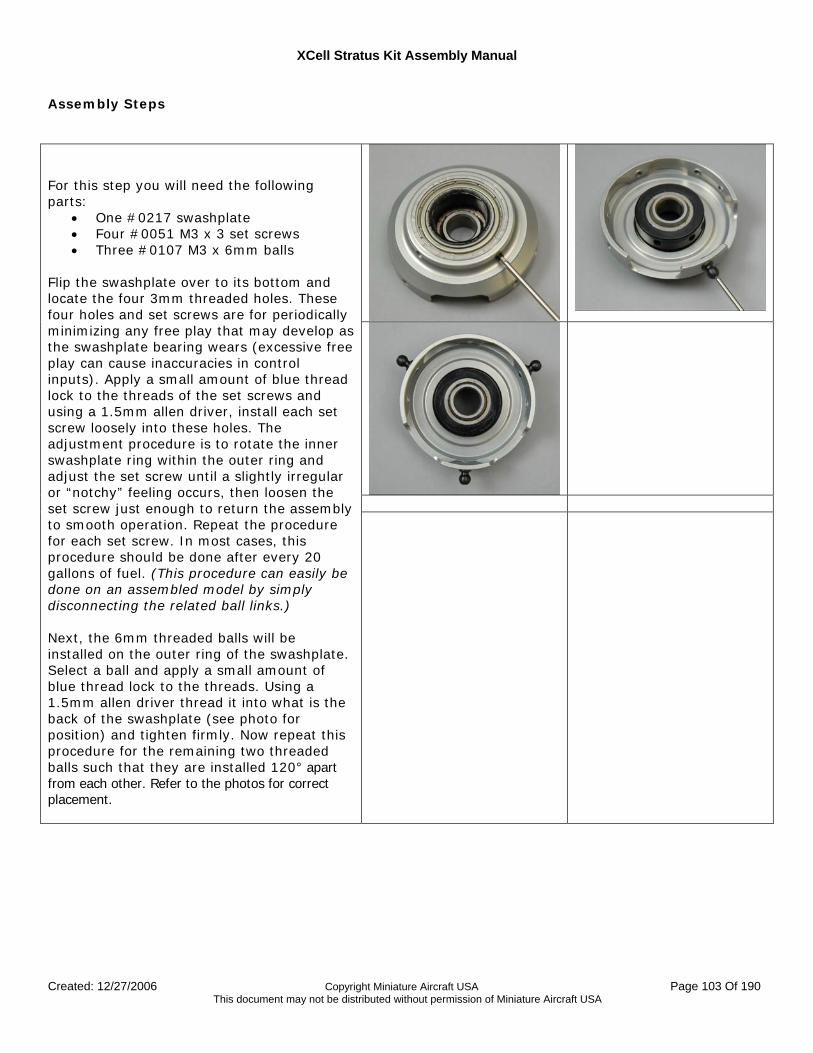
XCell Stratus Kit Assembly Manual
Created: 12/27/2006 Copyright Miniature Aircraft USA Page 103 Of 190 This document may not be distributed without permission of Miniature Aircraft USA
Assembly Steps
For this step you will need the following parts:
• One #0217 swashplate • Four #0051 M3 x 3 set screws • Three #0107 M3 x 6mm balls
Flip the swashplate over to its bottom and locate the four 3mm threaded holes. These four holes and set screws are for periodically minimizing any free play that may develop as the swashplate bearing wears (excessive free play can cause inaccuracies in control inputs). Apply a small amount of blue thread lock to the threads of the set screws and using a 1.5mm allen driver, install each set screw loosely into these holes. The adjustment procedure is to rotate the inner swashplate ring within the outer ring and adjust the set screw until a slightly irregular or “notchy” feeling occurs, then loosen the set screw just enough to return the assembly to smooth operation. Repeat the procedure for each set screw. In most cases, this procedure should be done after every 20 gallons of fuel. (This procedure can easily be done on an assembled model by simply disconnecting the related ball links.) Next, the 6mm threaded balls will be installed on the outer ring of the swashplate. Select a ball and apply a small amount of blue thread lock to the threads. Using a 1.5mm allen driver thread it into what is the back of the swashplate (see photo for position) and tighten firmly. Now repeat this procedure for the remaining two threaded balls such that they are installed 120° apart from each other. Refer to the photos for correct placement.
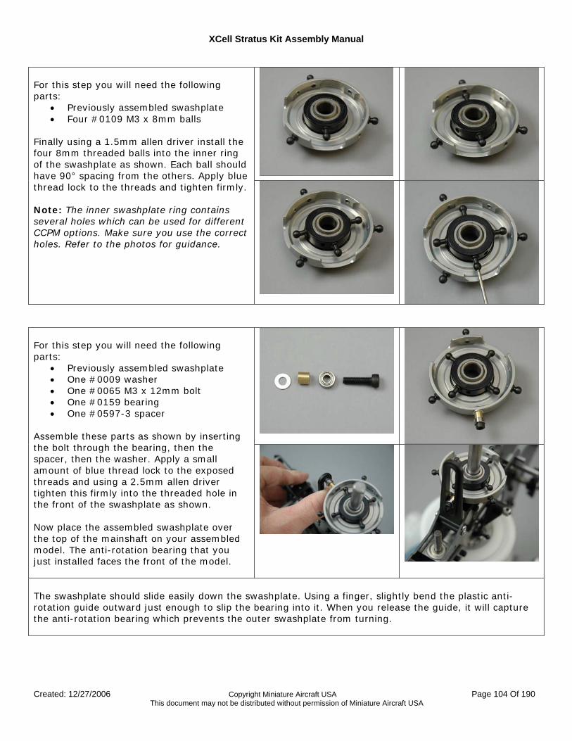
XCell Stratus Kit Assembly Manual
Created: 12/27/2006 Copyright Miniature Aircraft USA Page 104 Of 190 This document may not be distributed without permission of Miniature Aircraft USA
For this step you will need the following parts:
• Previously assembled swashplate • Four #0109 M3 x 8mm balls
Finally using a 1.5mm allen driver install the four 8mm threaded balls into the inner ring of the swashplate as shown. Each ball should have 90° spacing from the others. Apply blue thread lock to the threads and tighten firmly. Note: The inner swashplate ring contains several holes which can be used for different CCPM options. Make sure you use the correct holes. Refer to the photos for guidance.
For this step you will need the following parts:
• Previously assembled swashplate • One #0009 washer • One #0065 M3 x 12mm bolt • One #0159 bearing • One #0597-3 spacer
Assemble these parts as shown by inserting the bolt through the bearing, then the spacer, then the washer. Apply a small amount of blue thread lock to the exposed threads and using a 2.5mm allen driver tighten this firmly into the threaded hole in the front of the swashplate as shown. Now place the assembled swashplate over the top of the mainshaft on your assembled model. The anti-rotation bearing that you just installed faces the front of the model.
The swashplate should slide easily down the swashplate. Using a finger, slightly bend the plastic anti-rotation guide outward just enough to slip the bearing into it. When you release the guide, it will capture the anti-rotation bearing which prevents the outer swashplate from turning.
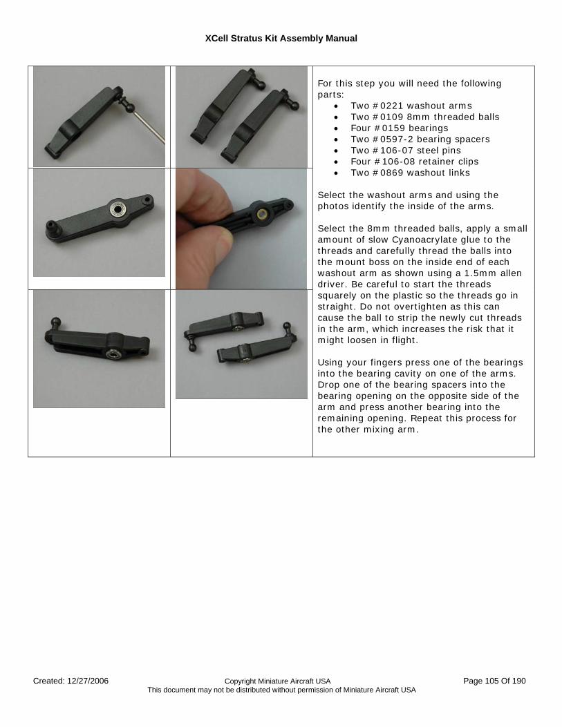
XCell Stratus Kit Assembly Manual
Created: 12/27/2006 Copyright Miniature Aircraft USA Page 105 Of 190 This document may not be distributed without permission of Miniature Aircraft USA
For this step you will need the following parts:
• Two #0221 washout arms • Two #0109 8mm threaded balls • Four #0159 bearings • Two #0597-2 bearing spacers • Two #106-07 steel pins • Four #106-08 retainer clips • Two #0869 washout links
Select the washout arms and using the photos identify the inside of the arms. Select the 8mm threaded balls, apply a small amount of slow Cyanoacrylate glue to the threads and carefully thread the balls into the mount boss on the inside end of each washout arm as shown using a 1.5mm allen driver. Be careful to start the threads squarely on the plastic so the threads go in straight. Do not overtighten as this can cause the ball to strip the newly cut threads in the arm, which increases the risk that it might loosen in flight. Using your fingers press one of the bearings into the bearing cavity on one of the arms. Drop one of the bearing spacers into the bearing opening on the opposite side of the arm and press another bearing into the remaining opening. Repeat this process for the other mixing arm.
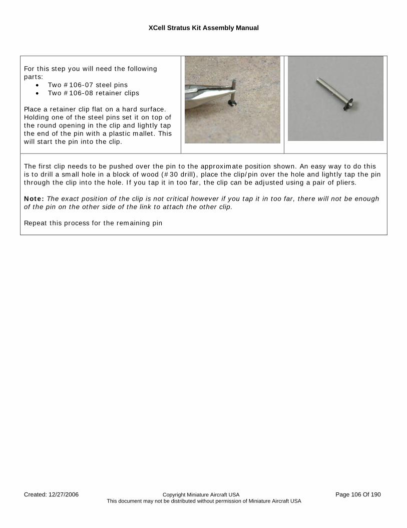
XCell Stratus Kit Assembly Manual
Created: 12/27/2006 Copyright Miniature Aircraft USA Page 106 Of 190 This document may not be distributed without permission of Miniature Aircraft USA
For this step you will need the following parts:
• Two #106-07 steel pins • Two #106-08 retainer clips
Place a retainer clip flat on a hard surface. Holding one of the steel pins set it on top of the round opening in the clip and lightly tap the end of the pin with a plastic mallet. This will start the pin into the clip.
The first clip needs to be pushed over the pin to the approximate position shown. An easy way to do this is to drill a small hole in a block of wood (#30 drill), place the clip/pin over the hole and lightly tap the pin through the clip into the hole. If you tap it in too far, the clip can be adjusted using a pair of pliers. Note: The exact position of the clip is not critical however if you tap it in too far, there will not be enough of the pin on the other side of the link to attach the other clip. Repeat this process for the remaining pin
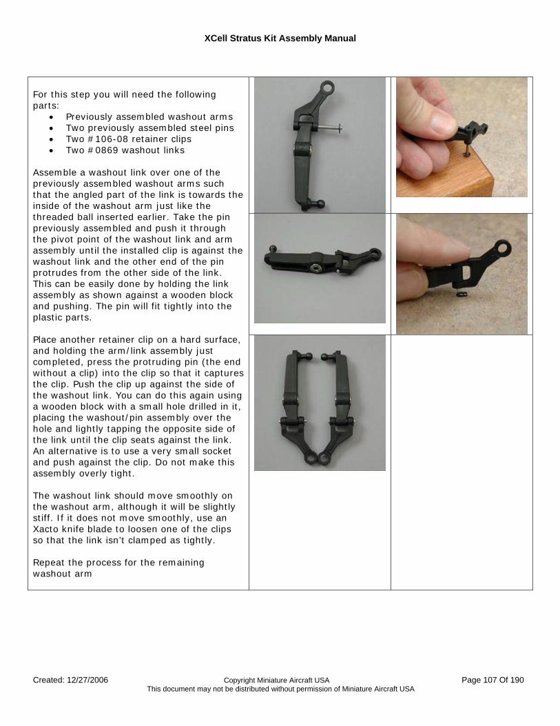
XCell Stratus Kit Assembly Manual
Created: 12/27/2006 Copyright Miniature Aircraft USA Page 107 Of 190 This document may not be distributed without permission of Miniature Aircraft USA
For this step you will need the following parts:
• Previously assembled washout arms • Two previously assembled steel pins • Two #106-08 retainer clips • Two #0869 washout links
Assemble a washout link over one of the previously assembled washout arms such that the angled part of the link is towards the inside of the washout arm just like the threaded ball inserted earlier. Take the pin previously assembled and push it through the pivot point of the washout link and arm assembly until the installed clip is against the washout link and the other end of the pin protrudes from the other side of the link. This can be easily done by holding the link assembly as shown against a wooden block and pushing. The pin will fit tightly into the plastic parts. Place another retainer clip on a hard surface, and holding the arm/link assembly just completed, press the protruding pin (the end without a clip) into the clip so that it captures the clip. Push the clip up against the side of the washout link. You can do this again using a wooden block with a small hole drilled in it, placing the washout/pin assembly over the hole and lightly tapping the opposite side of the link until the clip seats against the link. An alternative is to use a very small socket and push against the clip. Do not make this assembly overly tight. The washout link should move smoothly on the washout arm, although it will be slightly stiff. If it does not move smoothly, use an Xacto knife blade to loosen one of the clips so that the link isn’t clamped as tightly. Repeat the process for the remaining washout arm
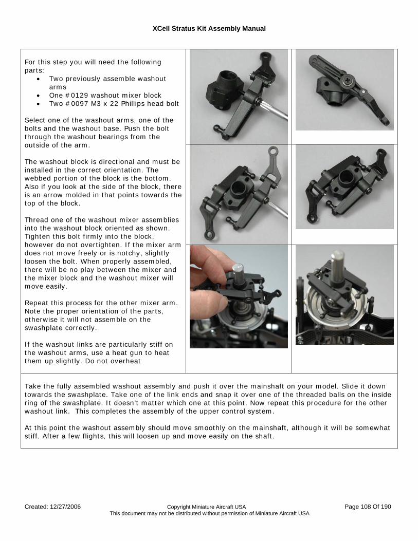
XCell Stratus Kit Assembly Manual
Created: 12/27/2006 Copyright Miniature Aircraft USA Page 108 Of 190 This document may not be distributed without permission of Miniature Aircraft USA
For this step you will need the following parts:
• Two previously assemble washout arms
• One #0129 washout mixer block • Two #0097 M3 x 22 Phillips head bolt
Select one of the washout arms, one of the bolts and the washout base. Push the bolt through the washout bearings from the outside of the arm. The washout block is directional and must be installed in the correct orientation. The webbed portion of the block is the bottom. Also if you look at the side of the block, there is an arrow molded in that points towards the top of the block. Thread one of the washout mixer assemblies into the washout block oriented as shown. Tighten this bolt firmly into the block, however do not overtighten. If the mixer arm does not move freely or is notchy, slightly loosen the bolt. When properly assembled, there will be no play between the mixer and the mixer block and the washout mixer will move easily. Repeat this process for the other mixer arm. Note the proper orientation of the parts, otherwise it will not assemble on the swashplate correctly. If the washout links are particularly stiff on the washout arms, use a heat gun to heat them up slightly. Do not overheat
Take the fully assembled washout assembly and push it over the mainshaft on your model. Slide it down towards the swashplate. Take one of the link ends and snap it over one of the threaded balls on the inside ring of the swashplate. It doesn’t matter which one at this point. Now repeat this procedure for the other washout link. This completes the assembly of the upper control system. At this point the washout assembly should move smoothly on the mainshaft, although it will be somewhat stiff. After a few flights, this will loosen up and move easily on the shaft.
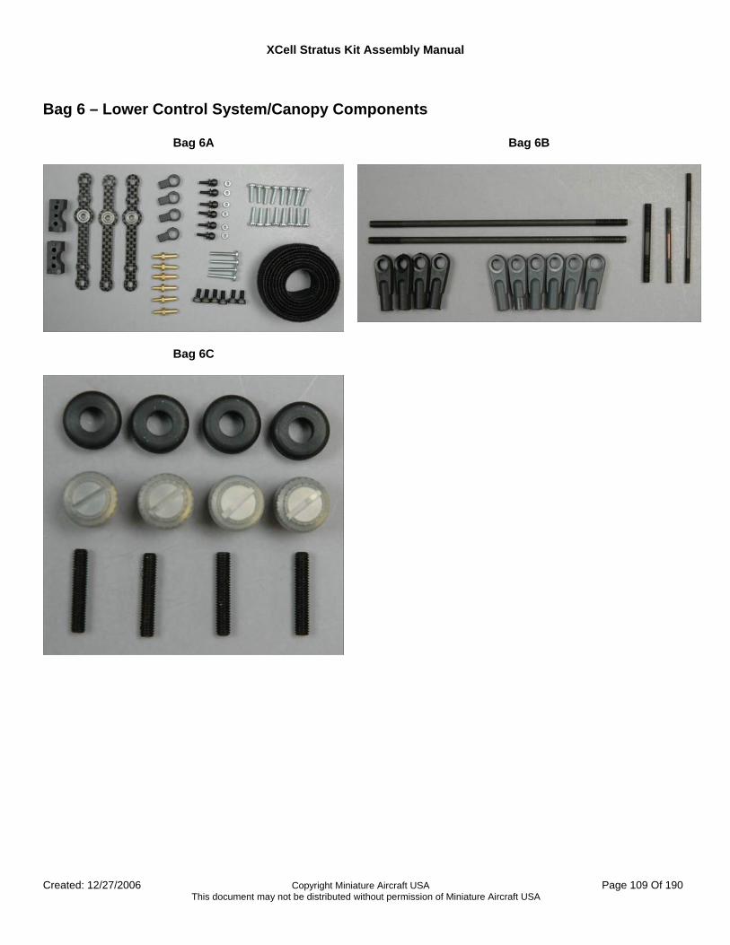
XCell Stratus Kit Assembly Manual
Created: 12/27/2006 Copyright Miniature Aircraft USA Page 109 Of 190 This document may not be distributed without permission of Miniature Aircraft USA
Bag 6 – Lower Control System/Canopy Components
Bag 6A
Bag 6B
Bag 6C
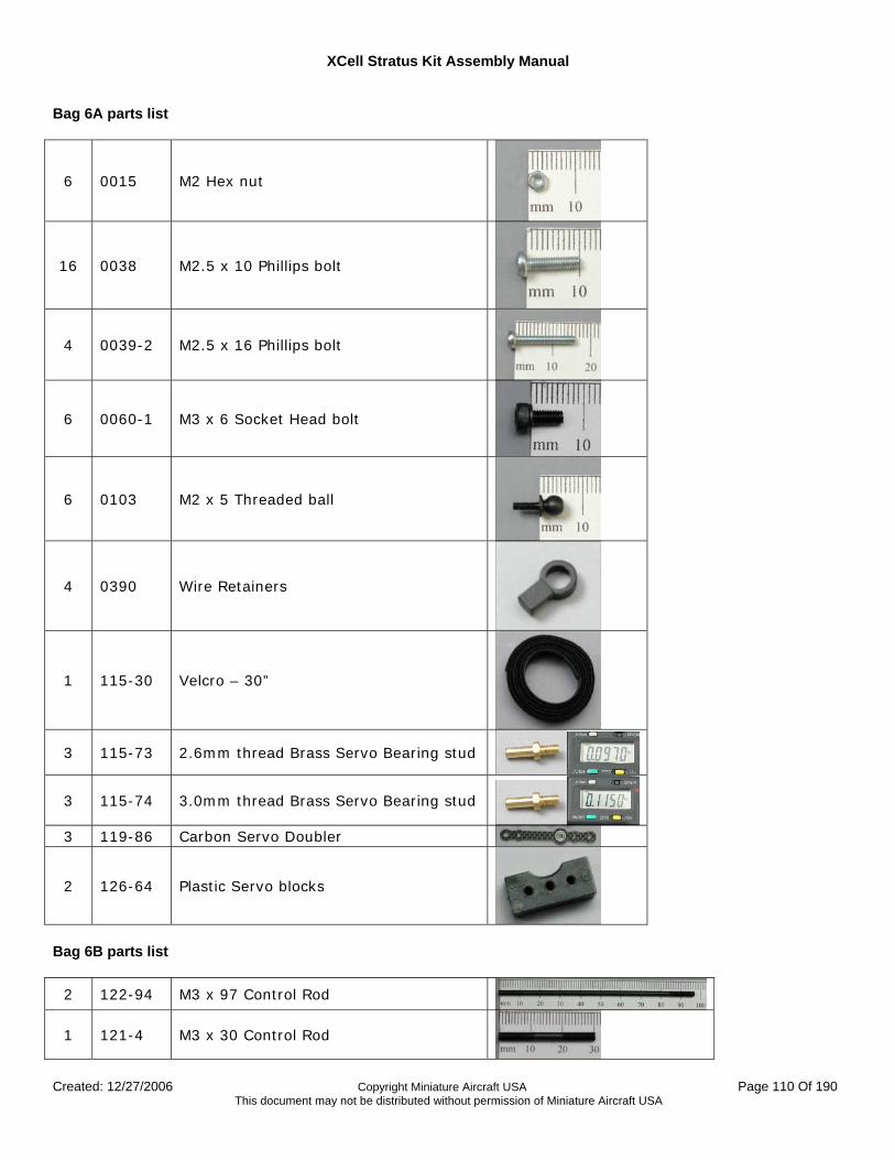
XCell Stratus Kit Assembly Manual
Created: 12/27/2006 Copyright Miniature Aircraft USA Page 110 Of 190 This document may not be distributed without permission of Miniature Aircraft USA
Bag 6A parts list
6 0015 M2 Hex nut
16 0038 M2.5 x 10 Phillips bolt
4 0039-2 M2.5 x 16 Phillips bolt
6 0060-1 M3 x 6 Socket Head bolt
6 0103 M2 x 5 Threaded ball
4 0390 Wire Retainers
1 115-30 Velcro – 30”
3 115-73 2.6mm thread Brass Servo Bearing stud
3 115-74 3.0mm thread Brass Servo Bearing stud
3 119-86 Carbon Servo Doubler
2 126-64 Plastic Servo blocks
Bag 6B parts list
2 122-94 M3 x 97 Control Rod
1 121-4 M3 x 30 Control Rod
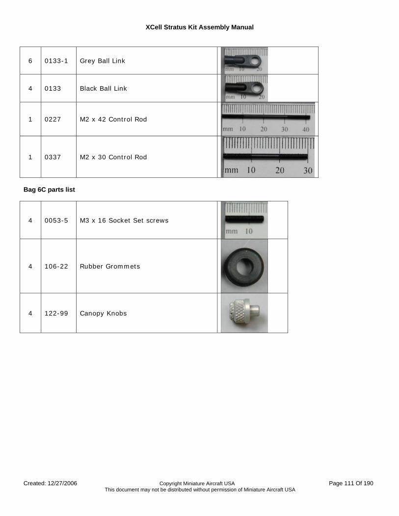
XCell Stratus Kit Assembly Manual
Created: 12/27/2006 Copyright Miniature Aircraft USA Page 111 Of 190 This document may not be distributed without permission of Miniature Aircraft USA
6 0133-1 Grey Ball Link
4 0133 Black Ball Link
1 0227 M2 x 42 Control Rod
1 0337 M2 x 30 Control Rod
Bag 6C parts list
4 0053-5 M3 x 16 Socket Set screws
4 106-22 Rubber Grommets
4 122-99 Canopy Knobs
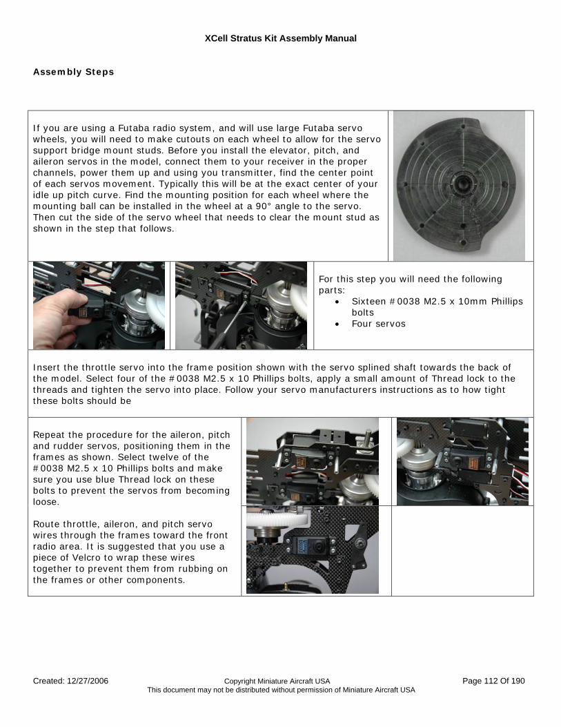
XCell Stratus Kit Assembly Manual
Created: 12/27/2006 Copyright Miniature Aircraft USA Page 112 Of 190 This document may not be distributed without permission of Miniature Aircraft USA
Assembly Steps If you are using a Futaba radio system, and will use large Futaba servo wheels, you will need to make cutouts on each wheel to allow for the servo support bridge mount studs. Before you install the elevator, pitch, and aileron servos in the model, connect them to your receiver in the proper channels, power them up and using you transmitter, find the center point of each servos movement. Typically this will be at the exact center of your idle up pitch curve. Find the mounting position for each wheel where the mounting ball can be installed in the wheel at a 90° angle to the servo. Then cut the side of the servo wheel that needs to clear the mount stud as shown in the step that follows.
For this step you will need the following parts:
• Sixteen #0038 M2.5 x 10mm Phillips bolts
• Four servos
Insert the throttle servo into the frame position shown with the servo splined shaft towards the back of the model. Select four of the #0038 M2.5 x 10 Phillips bolts, apply a small amount of Thread lock to the threads and tighten the servo into place. Follow your servo manufacturers instructions as to how tight these bolts should be
Repeat the procedure for the aileron, pitch and rudder servos, positioning them in the frames as shown. Select twelve of the #0038 M2.5 x 10 Phillips bolts and make sure you use blue Thread lock on these bolts to prevent the servos from becoming loose. Route throttle, aileron, and pitch servo wires through the frames toward the front radio area. It is suggested that you use a piece of Velcro to wrap these wires together to prevent them from rubbing on the frames or other components.
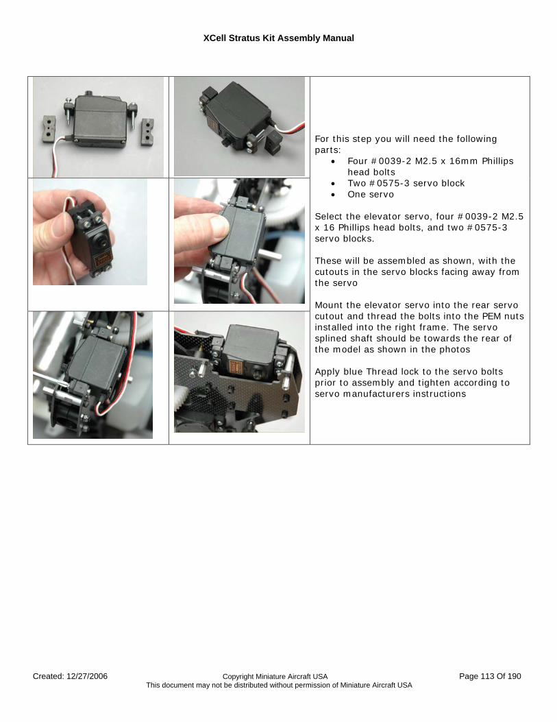
XCell Stratus Kit Assembly Manual
Created: 12/27/2006 Copyright Miniature Aircraft USA Page 113 Of 190 This document may not be distributed without permission of Miniature Aircraft USA
For this step you will need the following parts:
• Four #0039-2 M2.5 x 16mm Phillips head bolts
• Two #0575-3 servo block • One servo
Select the elevator servo, four #0039-2 M2.5 x 16 Phillips head bolts, and two #0575-3 servo blocks. These will be assembled as shown, with the cutouts in the servo blocks facing away from the servo Mount the elevator servo into the rear servo cutout and thread the bolts into the PEM nuts installed into the right frame. The servo splined shaft should be towards the rear of the model as shown in the photos Apply blue Thread lock to the servo bolts prior to assembly and tighten according to servo manufacturers instructions
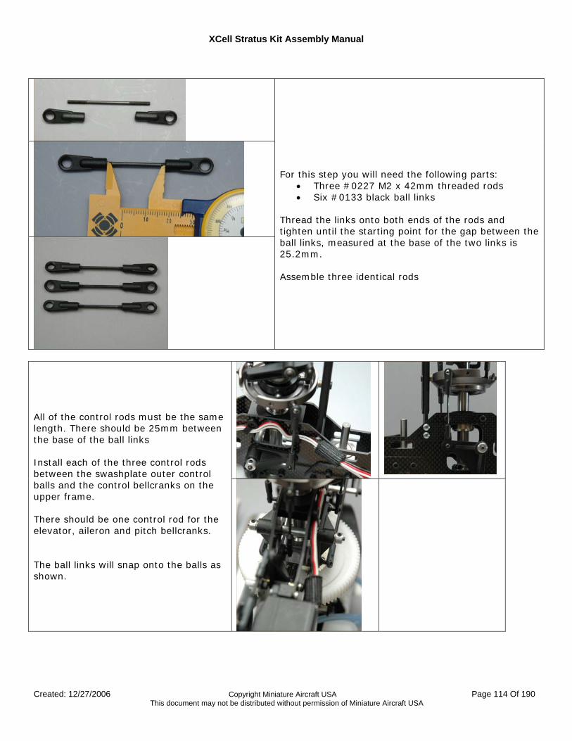
XCell Stratus Kit Assembly Manual
Created: 12/27/2006 Copyright Miniature Aircraft USA Page 114 Of 190 This document may not be distributed without permission of Miniature Aircraft USA
For this step you will need the following parts:
• Three #0227 M2 x 42mm threaded rods • Six #0133 black ball links
Thread the links onto both ends of the rods and tighten until the starting point for the gap between the ball links, measured at the base of the two links is 25.2mm. Assemble three identical rods
All of the control rods must be the same length. There should be 25mm between the base of the ball links Install each of the three control rods between the swashplate outer control balls and the control bellcranks on the upper frame. There should be one control rod for the elevator, aileron and pitch bellcranks. The ball links will snap onto the balls as shown.
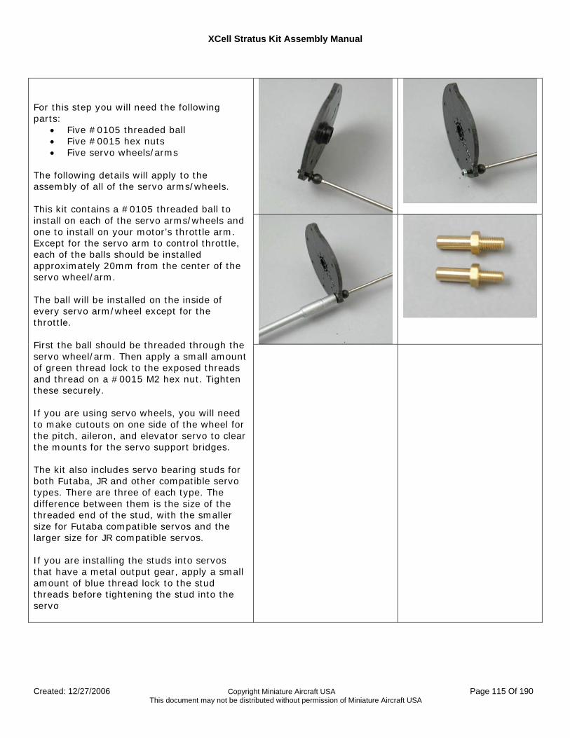
XCell Stratus Kit Assembly Manual
Created: 12/27/2006 Copyright Miniature Aircraft USA Page 115 Of 190 This document may not be distributed without permission of Miniature Aircraft USA
For this step you will need the following parts:
• Five #0105 threaded ball • Five #0015 hex nuts • Five servo wheels/arms
The following details will apply to the assembly of all of the servo arms/wheels. This kit contains a #0105 threaded ball to install on each of the servo arms/wheels and one to install on your motor’s throttle arm. Except for the servo arm to control throttle, each of the balls should be installed approximately 20mm from the center of the servo wheel/arm. The ball will be installed on the inside of every servo arm/wheel except for the throttle. First the ball should be threaded through the servo wheel/arm. Then apply a small amount of green thread lock to the exposed threads and thread on a #0015 M2 hex nut. Tighten these securely. If you are using servo wheels, you will need to make cutouts on one side of the wheel for the pitch, aileron, and elevator servo to clear the mounts for the servo support bridges. The kit also includes servo bearing studs for both Futaba, JR and other compatible servo types. There are three of each type. The difference between them is the size of the threaded end of the stud, with the smaller size for Futaba compatible servos and the larger size for JR compatible servos. If you are installing the studs into servos that have a metal output gear, apply a small amount of blue thread lock to the stud threads before tightening the stud into the servo
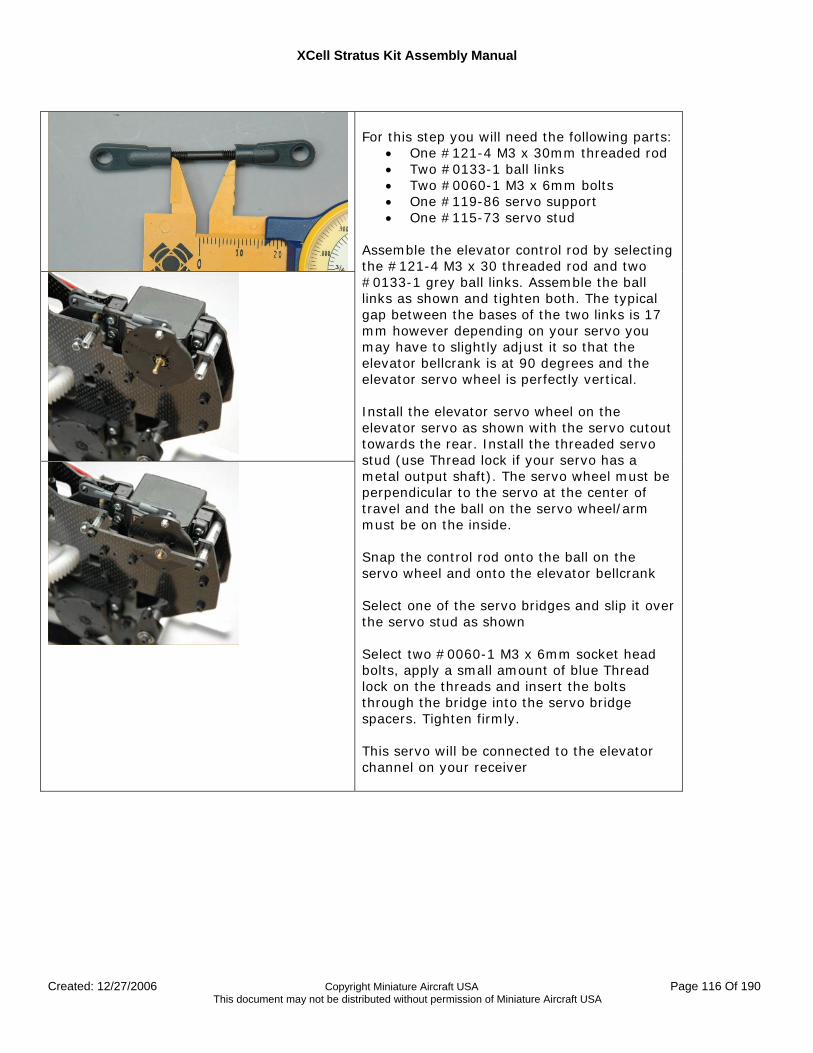
XCell Stratus Kit Assembly Manual
Created: 12/27/2006 Copyright Miniature Aircraft USA Page 116 Of 190 This document may not be distributed without permission of Miniature Aircraft USA
For this step you will need the following parts:
• One #121-4 M3 x 30mm threaded rod • Two #0133-1 ball links • Two #0060-1 M3 x 6mm bolts • One #119-86 servo support • One #115-73 servo stud
Assemble the elevator control rod by selecting the #121-4 M3 x 30 threaded rod and two #0133-1 grey ball links. Assemble the ball links as shown and tighten both. The typical gap between the bases of the two links is 17 mm however depending on your servo you may have to slightly adjust it so that the elevator bellcrank is at 90 degrees and the elevator servo wheel is perfectly vertical. Install the elevator servo wheel on the elevator servo as shown with the servo cutout towards the rear. Install the threaded servo stud (use Thread lock if your servo has a metal output shaft). The servo wheel must be perpendicular to the servo at the center of travel and the ball on the servo wheel/arm must be on the inside. Snap the control rod onto the ball on the servo wheel and onto the elevator bellcrank Select one of the servo bridges and slip it over the servo stud as shown Select two #0060-1 M3 x 6mm socket head bolts, apply a small amount of blue Thread lock on the threads and insert the bolts through the bridge into the servo bridge spacers. Tighten firmly. This servo will be connected to the elevator channel on your receiver
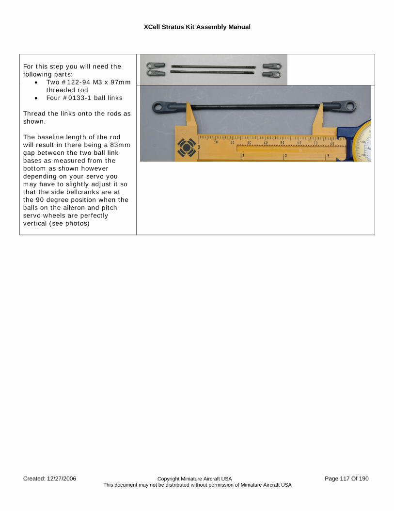
XCell Stratus Kit Assembly Manual
Created: 12/27/2006 Copyright Miniature Aircraft USA Page 117 Of 190 This document may not be distributed without permission of Miniature Aircraft USA
For this step you will need the following parts:
• Two #122-94 M3 x 97mm threaded rod
• Four #0133-1 ball links Thread the links onto the rods as shown. The baseline length of the rod will result in there being a 83mm gap between the two ball link bases as measured from the bottom as shown however depending on your servo you may have to slightly adjust it so that the side bellcranks are at the 90 degree position when the balls on the aileron and pitch servo wheels are perfectly vertical (see photos)
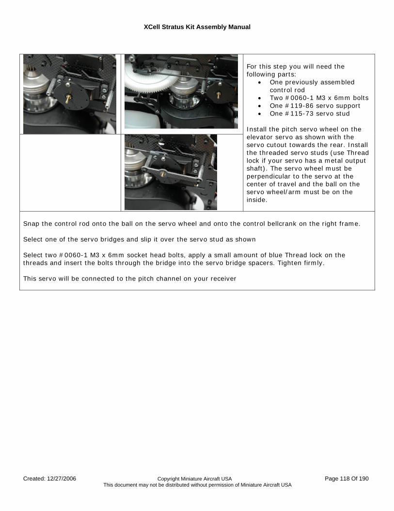
XCell Stratus Kit Assembly Manual
Created: 12/27/2006 Copyright Miniature Aircraft USA Page 118 Of 190 This document may not be distributed without permission of Miniature Aircraft USA
For this step you will need the following parts:
• One previously assembled control rod
• Two #0060-1 M3 x 6mm bolts • One #119-86 servo support • One #115-73 servo stud
Install the pitch servo wheel on the elevator servo as shown with the servo cutout towards the rear. Install the threaded servo studs (use Thread lock if your servo has a metal output shaft). The servo wheel must be perpendicular to the servo at the center of travel and the ball on the servo wheel/arm must be on the inside.
Snap the control rod onto the ball on the servo wheel and onto the control bellcrank on the right frame. Select one of the servo bridges and slip it over the servo stud as shown Select two #0060-1 M3 x 6mm socket head bolts, apply a small amount of blue Thread lock on the threads and insert the bolts through the bridge into the servo bridge spacers. Tighten firmly. This servo will be connected to the pitch channel on your receiver
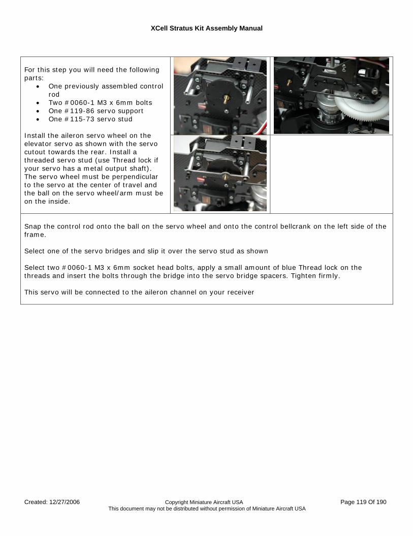
XCell Stratus Kit Assembly Manual
Created: 12/27/2006 Copyright Miniature Aircraft USA Page 119 Of 190 This document may not be distributed without permission of Miniature Aircraft USA
For this step you will need the following parts:
• One previously assembled control rod
• Two #0060-1 M3 x 6mm bolts • One #119-86 servo support • One #115-73 servo stud
Install the aileron servo wheel on the elevator servo as shown with the servo cutout towards the rear. Install a threaded servo stud (use Thread lock if your servo has a metal output shaft). The servo wheel must be perpendicular to the servo at the center of travel and the ball on the servo wheel/arm must be on the inside.
Snap the control rod onto the ball on the servo wheel and onto the control bellcrank on the left side of the frame. Select one of the servo bridges and slip it over the servo stud as shown Select two #0060-1 M3 x 6mm socket head bolts, apply a small amount of blue Thread lock on the threads and insert the bolts through the bridge into the servo bridge spacers. Tighten firmly. This servo will be connected to the aileron channel on your receiver
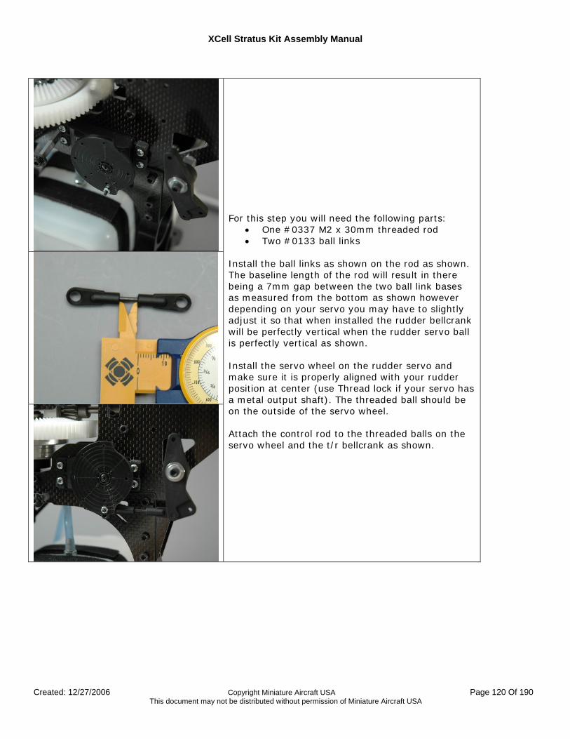
XCell Stratus Kit Assembly Manual
Created: 12/27/2006 Copyright Miniature Aircraft USA Page 120 Of 190 This document may not be distributed without permission of Miniature Aircraft USA
For this step you will need the following parts:
• One #0337 M2 x 30mm threaded rod • Two #0133 ball links
Install the ball links as shown on the rod as shown. The baseline length of the rod will result in there being a 7mm gap between the two ball link bases as measured from the bottom as shown however depending on your servo you may have to slightly adjust it so that when installed the rudder bellcrank will be perfectly vertical when the rudder servo ball is perfectly vertical as shown. Install the servo wheel on the rudder servo and make sure it is properly aligned with your rudder position at center (use Thread lock if your servo has a metal output shaft). The threaded ball should be on the outside of the servo wheel. Attach the control rod to the threaded balls on the servo wheel and the t/r bellcrank as shown.
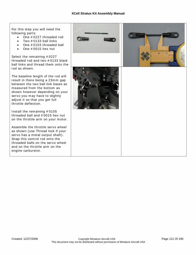
XCell Stratus Kit Assembly Manual
Created: 12/27/2006 Copyright Miniature Aircraft USA Page 121 Of 190 This document may not be distributed without permission of Miniature Aircraft USA
For this step you will need the following parts:
• One #0227 threaded rod • Two #0133 ball links • One #0103 threaded ball • One #0015 hex nut
Select the remaining #0227 threaded rod and two #0133 black ball links and thread them onto the rod as shown. The baseline length of the rod will result in there being a 23mm gap between the two ball link bases as measured from the bottom as shown however depending on your servo you may have to slightly adjust it so that you get full throttle deflection. Install the remaining #0105 threaded ball and #0015 hex nut on the throttle arm on your motor. Assemble the throttle servo wheel as shown (use Thread lock if your servo has a metal output shaft). Snap this control rod onto the threaded balls on the servo wheel and on the throttle arm on the engine carburetor.
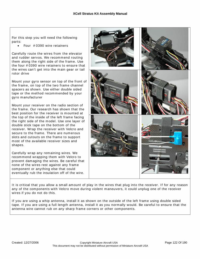
XCell Stratus Kit Assembly Manual
Created: 12/27/2006 Copyright Miniature Aircraft USA Page 122 Of 190 This document may not be distributed without permission of Miniature Aircraft USA
For this step you will need the following parts:
• Four #0390 wire retainers Carefully route the wires from the elevator and rudder servos. We recommend routing them along the right side of the frame. Use the four #0390 wire retainers to ensure that the wires can’t get into the main gear or tail rotor drive Mount your gyro sensor on top of the front of the frame, on top of the two frame channel spacers as shown. Use either double sided tape or the method recommended by your gyro manufacturer Mount your receiver on the radio section of the frame. Our research has shown that the best position for the receiver is mounted at the top of the inside of the left frame facing the right side of the model. Use one layer of double stick tape on the bottom of the receiver. Wrap the receiver with Velcro and secure to the frame. There are numerous slots and cutouts on the frame to support most of the available receiver sizes and shapes. Carefully wrap any remaining wires. We recommend wrapping them with Velcro to prevent damaging the wires. Be careful that none of the wires rest against any frame component or anything else that could eventually rub the insulation off of the wire.
It is critical that you allow a small amount of play in the wires that plug into the receiver. If for any reason any of the components with Velcro move during violent maneuvers, it could unplug one of the receiver wires if you do not do this. If you are using a whip antenna, install it as shown on the outside of the left frame using double sided tape. If you are using a full length antenna, install it as you normally would. Be careful to ensure that the antenna wire cannot rub on any sharp frame corners or other components.
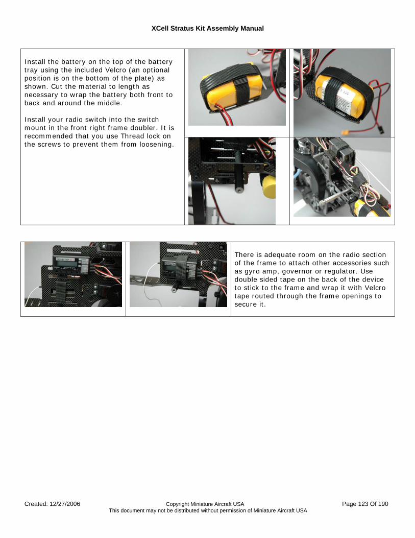
XCell Stratus Kit Assembly Manual
Created: 12/27/2006 Copyright Miniature Aircraft USA Page 123 Of 190 This document may not be distributed without permission of Miniature Aircraft USA
Install the battery on the top of the battery tray using the included Velcro (an optional position is on the bottom of the plate) as shown. Cut the material to length as necessary to wrap the battery both front to back and around the middle. Install your radio switch into the switch mount in the front right frame doubler. It is recommended that you use Thread lock on the screws to prevent them from loosening.
There is adequate room on the radio section of the frame to attach other accessories such as gyro amp, governor or regulator. Use double sided tape on the back of the device to stick to the frame and wrap it with Velcro tape routed through the frame openings to secure it.
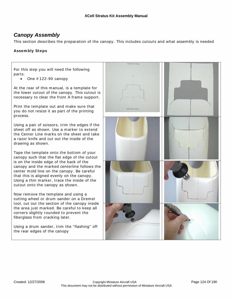
XCell Stratus Kit Assembly Manual
Created: 12/27/2006 Copyright Miniature Aircraft USA Page 124 Of 190 This document may not be distributed without permission of Miniature Aircraft USA
Canopy Assembly This section describes the preparation of the canopy. This includes cutouts and what assembly is needed Assembly Steps
For this step you will need the following parts:
• One #122-90 canopy At the rear of this manual, is a template for the lower cutout of the canopy. This cutout is necessary to clear the front A frame support. Print the template out and make sure that you do not resize it as part of the printing process. Using a pair of scissors, trim the edges if the sheet off as shown. Use a marker to extend the Center Line marks on the sheet and take a razor knife and cut out the inside of the drawing as shown. Tape the template onto the bottom of your canopy such that the flat edge of the cutout is on the inside edge of the back of the canopy and the marked centerline follows the center mold line on the canopy. Be careful that this is aligned evenly on the canopy. Using a thin marker, trace the inside of the cutout onto the canopy as shown. Now remove the template and using a cutting wheel or drum sander on a Dremel tool, cut out the section of the canopy inside the area just marked. Be careful to keep all corners slightly rounded to prevent the fiberglass from cracking later. Using a drum sander, trim the “flashing” off the rear edges of the canopy
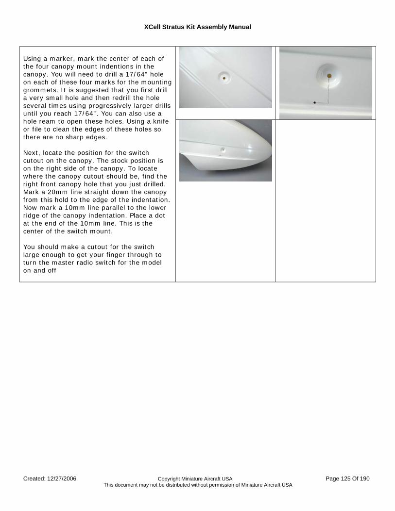
XCell Stratus Kit Assembly Manual
Created: 12/27/2006 Copyright Miniature Aircraft USA Page 125 Of 190 This document may not be distributed without permission of Miniature Aircraft USA
Using a marker, mark the center of each of the four canopy mount indentions in the canopy. You will need to drill a 17/64” hole on each of these four marks for the mounting grommets. It is suggested that you first drill a very small hole and then redrill the hole several times using progressively larger drills until you reach 17/64”. You can also use a hole ream to open these holes. Using a knife or file to clean the edges of these holes so there are no sharp edges. Next, locate the position for the switch cutout on the canopy. The stock position is on the right side of the canopy. To locate where the canopy cutout should be, find the right front canopy hole that you just drilled. Mark a 20mm line straight down the canopy from this hold to the edge of the indentation. Now mark a 10mm line parallel to the lower ridge of the canopy indentation. Place a dot at the end of the 10mm line. This is the center of the switch mount. You should make a cutout for the switch large enough to get your finger through to turn the master radio switch for the model on and off
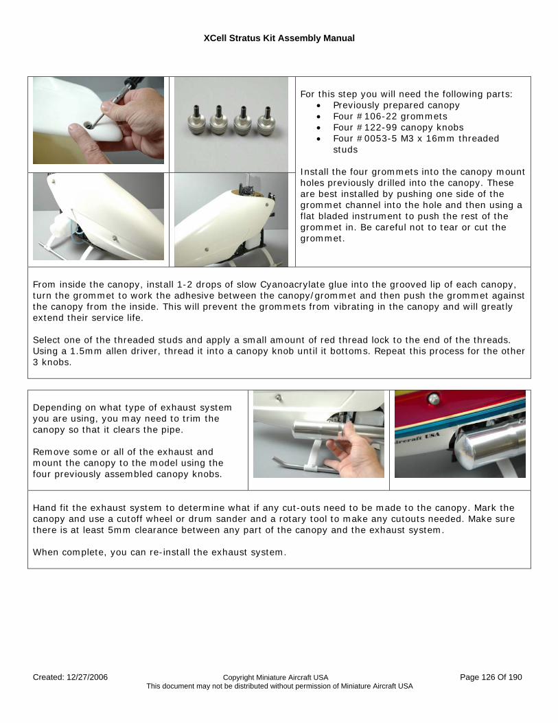
XCell Stratus Kit Assembly Manual
Created: 12/27/2006 Copyright Miniature Aircraft USA Page 126 Of 190 This document may not be distributed without permission of Miniature Aircraft USA
For this step you will need the following parts:
• Previously prepared canopy • Four #106-22 grommets • Four #122-99 canopy knobs • Four #0053-5 M3 x 16mm threaded
studs Install the four grommets into the canopy mount holes previously drilled into the canopy. These are best installed by pushing one side of the grommet channel into the hole and then using a flat bladed instrument to push the rest of the grommet in. Be careful not to tear or cut the grommet.
From inside the canopy, install 1-2 drops of slow Cyanoacrylate glue into the grooved lip of each canopy, turn the grommet to work the adhesive between the canopy/grommet and then push the grommet against the canopy from the inside. This will prevent the grommets from vibrating in the canopy and will greatly extend their service life. Select one of the threaded studs and apply a small amount of red thread lock to the end of the threads. Using a 1.5mm allen driver, thread it into a canopy knob until it bottoms. Repeat this process for the other 3 knobs. Depending on what type of exhaust system you are using, you may need to trim the canopy so that it clears the pipe. Remove some or all of the exhaust and mount the canopy to the model using the four previously assembled canopy knobs.
Hand fit the exhaust system to determine what if any cut-outs need to be made to the canopy. Mark the canopy and use a cutoff wheel or drum sander and a rotary tool to make any cutouts needed. Make sure there is at least 5mm clearance between any part of the canopy and the exhaust system. When complete, you can re-install the exhaust system.
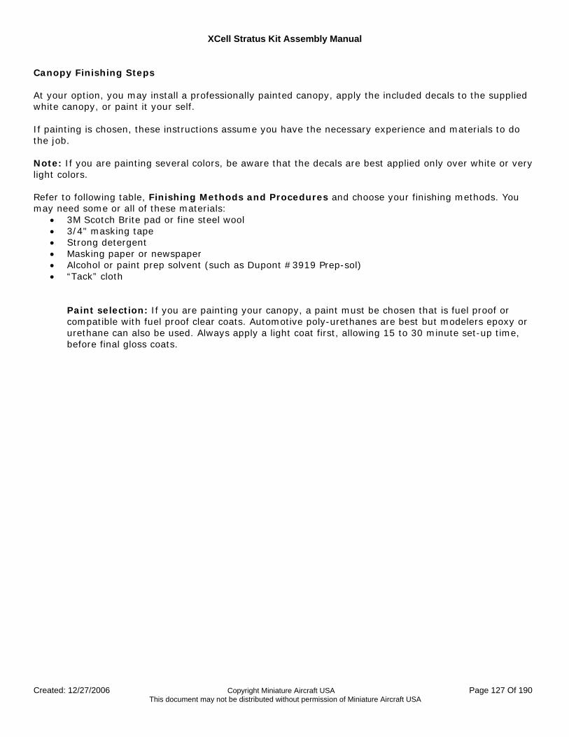
XCell Stratus Kit Assembly Manual
Created: 12/27/2006 Copyright Miniature Aircraft USA Page 127 Of 190 This document may not be distributed without permission of Miniature Aircraft USA
Canopy Finishing Steps At your option, you may install a professionally painted canopy, apply the included decals to the supplied white canopy, or paint it your self. If painting is chosen, these instructions assume you have the necessary experience and materials to do the job. Note: If you are painting several colors, be aware that the decals are best applied only over white or very light colors. Refer to following table, Finishing Methods and Procedures and choose your finishing methods. You may need some or all of these materials:
• 3M Scotch Brite pad or fine steel wool • 3/4" masking tape • Strong detergent • Masking paper or newspaper • Alcohol or paint prep solvent (such as Dupont #3919 Prep-sol) • “Tack” cloth
Paint selection: If you are painting your canopy, a paint must be chosen that is fuel proof or compatible with fuel proof clear coats. Automotive poly-urethanes are best but modelers epoxy or urethane can also be used. Always apply a light coat first, allowing 15 to 30 minute set-up time, before final gloss coats.
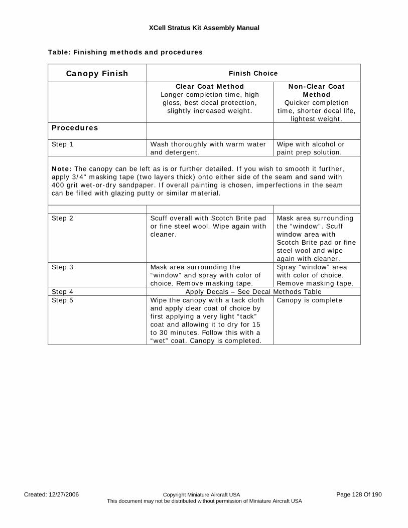
XCell Stratus Kit Assembly Manual
Created: 12/27/2006 Copyright Miniature Aircraft USA Page 128 Of 190 This document may not be distributed without permission of Miniature Aircraft USA
Table: Finishing methods and procedures
Canopy Finish Finish Choice
Clear Coat Method Longer completion time, high gloss, best decal protection, slightly increased weight.
Non-Clear Coat Method
Quicker completion time, shorter decal life,
lightest weight. Procedures
Step 1 Wash thoroughly with warm water and detergent.
Wipe with alcohol or paint prep solution.
Note: The canopy can be left as is or further detailed. If you wish to smooth it further, apply 3/4" masking tape (two layers thick) onto either side of the seam and sand with 400 grit wet-or-dry sandpaper. If overall painting is chosen, imperfections in the seam can be filled with glazing putty or similar material. Step 2 Scuff overall with Scotch Brite pad
or fine steel wool. Wipe again with cleaner.
Mask area surrounding the “window”. Scuff window area with Scotch Brite pad or fine steel wool and wipe again with cleaner.
Step 3 Mask area surrounding the “window” and spray with color of choice. Remove masking tape.
Spray “window” area with color of choice. Remove masking tape.
Step 4 Apply Decals – See Decal Methods Table Step 5 Wipe the canopy with a tack cloth
and apply clear coat of choice by first applying a very light “tack” coat and allowing it to dry for 15 to 30 minutes. Follow this with a “wet” coat. Canopy is completed.
Canopy is complete
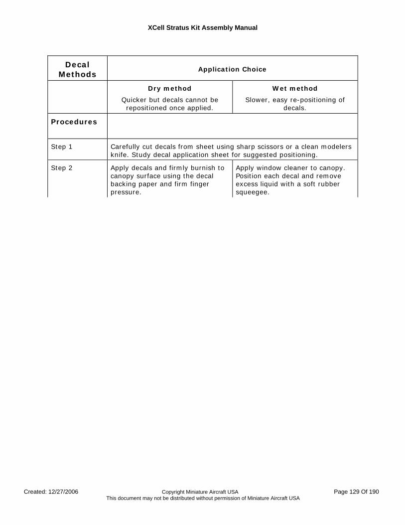
XCell Stratus Kit Assembly Manual
Created: 12/27/2006 Copyright Miniature Aircraft USA Page 129 Of 190 This document may not be distributed without permission of Miniature Aircraft USA
Decal Methods
Application Choice
Dry method
Quicker but decals cannot be repositioned once applied.
Wet method
Slower, easy re-positioning of decals.
Procedures
Step 1 Carefully cut decals from sheet using sharp scissors or a clean modelers knife. Study decal application sheet for suggested positioning.
Step 2 Apply decals and firmly burnish to canopy surface using the decal backing paper and firm finger pressure.
Apply window cleaner to canopy. Position each decal and remove excess liquid with a soft rubber squeegee.
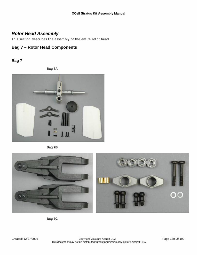
XCell Stratus Kit Assembly Manual
Created: 12/27/2006 Copyright Miniature Aircraft USA Page 130 Of 190 This document may not be distributed without permission of Miniature Aircraft USA
Rotor Head Assembly This section describes the assembly of the entire rotor head
Bag 7 – Rotor Head Components Bag 7
Bag 7A
Bag 7B
Bag 7C
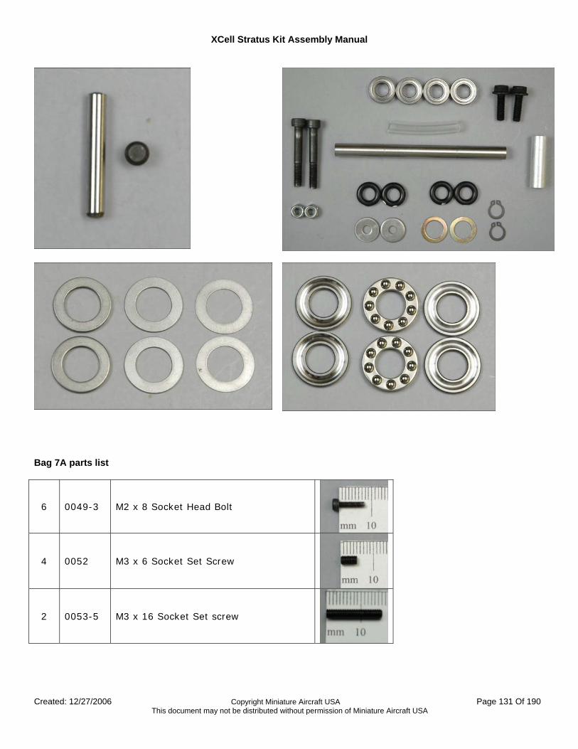
XCell Stratus Kit Assembly Manual
Created: 12/27/2006 Copyright Miniature Aircraft USA Page 131 Of 190 This document may not be distributed without permission of Miniature Aircraft USA
Bag 7A parts list
6 0049-3 M2 x 8 Socket Head Bolt
4 0052 M3 x 6 Socket Set Screw
2 0053-5 M3 x 16 Socket Set screw
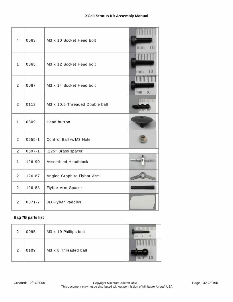
XCell Stratus Kit Assembly Manual
Created: 12/27/2006 Copyright Miniature Aircraft USA Page 132 Of 190 This document may not be distributed without permission of Miniature Aircraft USA
4 0063 M3 x 10 Socket Head Bolt
1 0065 M3 x 12 Socket Head bolt
2 0067 M3 x 14 Socket Head bolt
2 0113 M3 x 10.5 Threaded Double ball
1 0509 Head button
2 0555-1 Control Ball w/M3 Hole
2 0597-1 .125” Brass spacer
1 126-90 Assembled Headblock
2 126-87 Angled Graphite Flybar Arm
2 126-88 Flybar Arm Spacer
2 0871-7 3D Flybar Paddles
Bag 7B parts list
2 0095 M3 x 19 Phillips bolt
2 0109 M3 x 8 Threaded ball
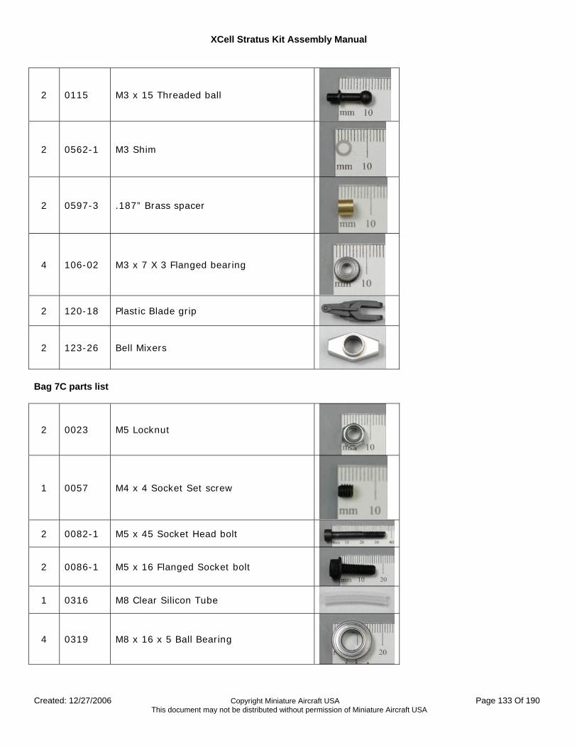
XCell Stratus Kit Assembly Manual
Created: 12/27/2006 Copyright Miniature Aircraft USA Page 133 Of 190 This document may not be distributed without permission of Miniature Aircraft USA
2 0115 M3 x 15 Threaded ball
2 0562-1 M3 Shim
2 0597-3 .187” Brass spacer
4 106-02 M3 x 7 X 3 Flanged bearing
2 120-18 Plastic Blade grip
2 123-26 Bell Mixers
Bag 7C parts list
2 0023 M5 Locknut
1 0057 M4 x 4 Socket Set screw
2 0082-1 M5 x 45 Socket Head bolt
2 0086-1 M5 x 16 Flanged Socket bolt
1 0316 M8 Clear Silicon Tube
4 0319 M8 x 16 x 5 Ball Bearing
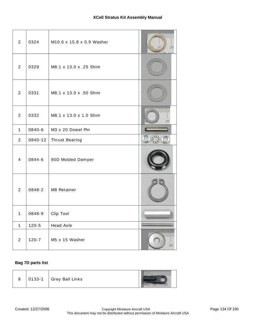
XCell Stratus Kit Assembly Manual
Created: 12/27/2006 Copyright Miniature Aircraft USA Page 134 Of 190 This document may not be distributed without permission of Miniature Aircraft USA
2 0324 M10.6 x 15.8 x 0.9 Washer
2 0329 M8.1 x 13.0 x .25 Shim
2 0331 M8.1 x 13.0 x .50 Shim
2 0332 M8.1 x 13.0 x 1.0 Shim
1 0840-6 M3 x 20 Dowel Pin
2 0840-12 Thrust Bearing
4 0844-6 90D Molded Damper
2 0848-2 M8 Retainer
1 0848-9 Clip Tool
1 120-5 Head Axle
2 120-7 M5 x 15 Washer
Bag 7D parts list
8 0133-1 Grey Ball Links
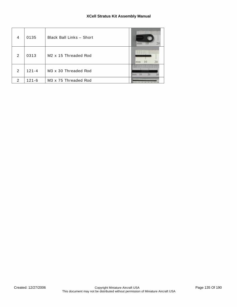
XCell Stratus Kit Assembly Manual
Created: 12/27/2006 Copyright Miniature Aircraft USA Page 135 Of 190 This document may not be distributed without permission of Miniature Aircraft USA
4 0135 Black Ball Links – Short
2 0313 M2 x 15 Threaded Rod
2 121-4 M3 x 30 Threaded Rod
2 121-6 M3 x 75 Threaded Rod
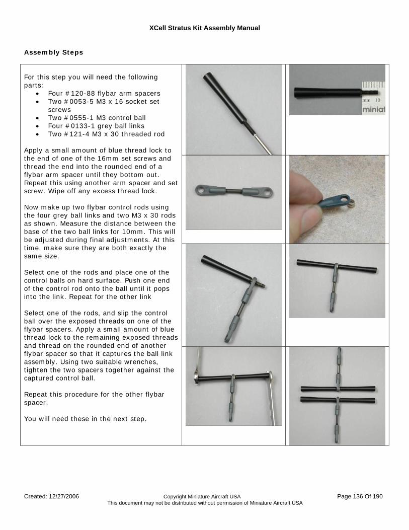
XCell Stratus Kit Assembly Manual
Created: 12/27/2006 Copyright Miniature Aircraft USA Page 136 Of 190 This document may not be distributed without permission of Miniature Aircraft USA
Assembly Steps
For this step you will need the following parts:
• Four #120-88 flybar arm spacers • Two #0053-5 M3 x 16 socket set
screws • Two #0555-1 M3 control ball • Four #0133-1 grey ball links • Two #121-4 M3 x 30 threaded rod
Apply a small amount of blue thread lock to the end of one of the 16mm set screws and thread the end into the rounded end of a flybar arm spacer until they bottom out. Repeat this using another arm spacer and set screw. Wipe off any excess thread lock. Now make up two flybar control rods using the four grey ball links and two M3 x 30 rods as shown. Measure the distance between the base of the two ball links for 10mm. This will be adjusted during final adjustments. At this time, make sure they are both exactly the same size. Select one of the rods and place one of the control balls on hard surface. Push one end of the control rod onto the ball until it pops into the link. Repeat for the other link Select one of the rods, and slip the control ball over the exposed threads on one of the flybar spacers. Apply a small amount of blue thread lock to the remaining exposed threads and thread on the rounded end of another flybar spacer so that it captures the ball link assembly. Using two suitable wrenches, tighten the two spacers together against the captured control ball. Repeat this procedure for the other flybar spacer. You will need these in the next step.
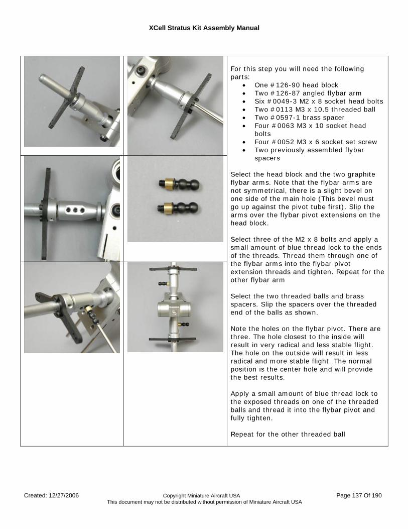
XCell Stratus Kit Assembly Manual
Created: 12/27/2006 Copyright Miniature Aircraft USA Page 137 Of 190 This document may not be distributed without permission of Miniature Aircraft USA
For this step you will need the following parts:
• One #126-90 head block • Two #126-87 angled flybar arm • Six #0049-3 M2 x 8 socket head bolts • Two #0113 M3 x 10.5 threaded ball • Two #0597-1 brass spacer • Four #0063 M3 x 10 socket head
bolts • Four #0052 M3 x 6 socket set screw • Two previously assembled flybar
spacers Select the head block and the two graphite flybar arms. Note that the flybar arms are not symmetrical, there is a slight bevel on one side of the main hole (This bevel must go up against the pivot tube first). Slip the arms over the flybar pivot extensions on the head block. Select three of the M2 x 8 bolts and apply a small amount of blue thread lock to the ends of the threads. Thread them through one of the flybar arms into the flybar pivot extension threads and tighten. Repeat for the other flybar arm Select the two threaded balls and brass spacers. Slip the spacers over the threaded end of the balls as shown. Note the holes on the flybar pivot. There are three. The hole closest to the inside will result in very radical and less stable flight. The hole on the outside will result in less radical and more stable flight. The normal position is the center hole and will provide the best results. Apply a small amount of blue thread lock to the exposed threads on one of the threaded balls and thread it into the flybar pivot and fully tighten. Repeat for the other threaded ball
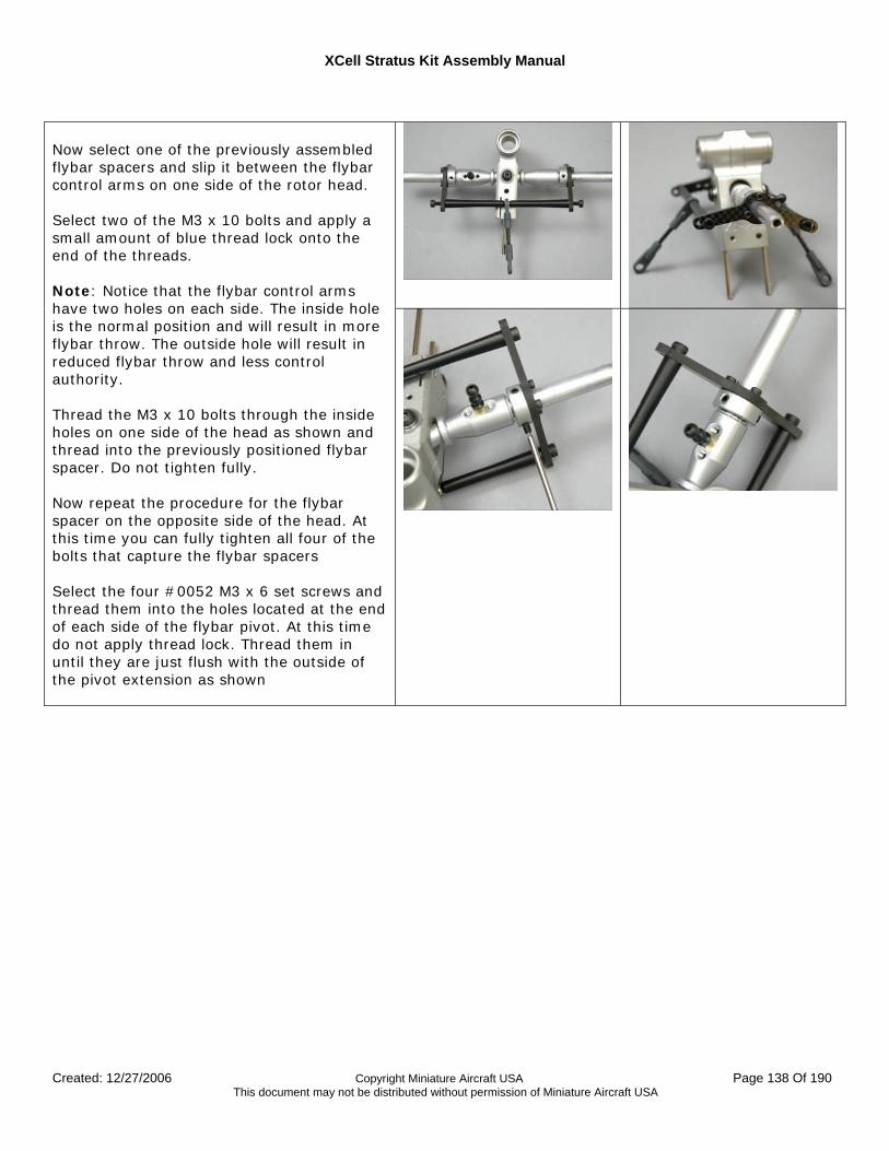
XCell Stratus Kit Assembly Manual
Created: 12/27/2006 Copyright Miniature Aircraft USA Page 138 Of 190 This document may not be distributed without permission of Miniature Aircraft USA
Now select one of the previously assembled flybar spacers and slip it between the flybar control arms on one side of the rotor head. Select two of the M3 x 10 bolts and apply a small amount of blue thread lock onto the end of the threads. Note: Notice that the flybar control arms have two holes on each side. The inside hole is the normal position and will result in more flybar throw. The outside hole will result in reduced flybar throw and less control authority. Thread the M3 x 10 bolts through the inside holes on one side of the head as shown and thread into the previously positioned flybar spacer. Do not tighten fully. Now repeat the procedure for the flybar spacer on the opposite side of the head. At this time you can fully tighten all four of the bolts that capture the flybar spacers Select the four #0052 M3 x 6 set screws and thread them into the holes located at the end of each side of the flybar pivot. At this time do not apply thread lock. Thread them in until they are just flush with the outside of the pivot extension as shown
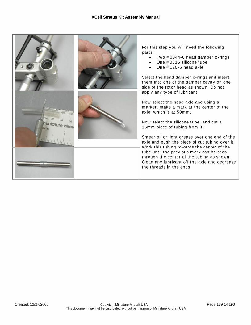
XCell Stratus Kit Assembly Manual
Created: 12/27/2006 Copyright Miniature Aircraft USA Page 139 Of 190 This document may not be distributed without permission of Miniature Aircraft USA
For this step you will need the following parts:
• Two #0844-6 head damper o-rings • One #0316 silicone tube • One #120-5 head axle
Select the head damper o-rings and insert them into one of the damper cavity on one side of the rotor head as shown. Do not apply any type of lubricant Now select the head axle and using a marker, make a mark at the center of the axle, which is at 50mm. Now select the silicone tube, and cut a 15mm piece of tubing from it. Smear oil or light grease over one end of the axle and push the piece of cut tubing over it. Work this tubing towards the center of the tube until the previous mark can be seen through the center of the tubing as shown. Clean any lubricant off the axle and degrease the threads in the ends
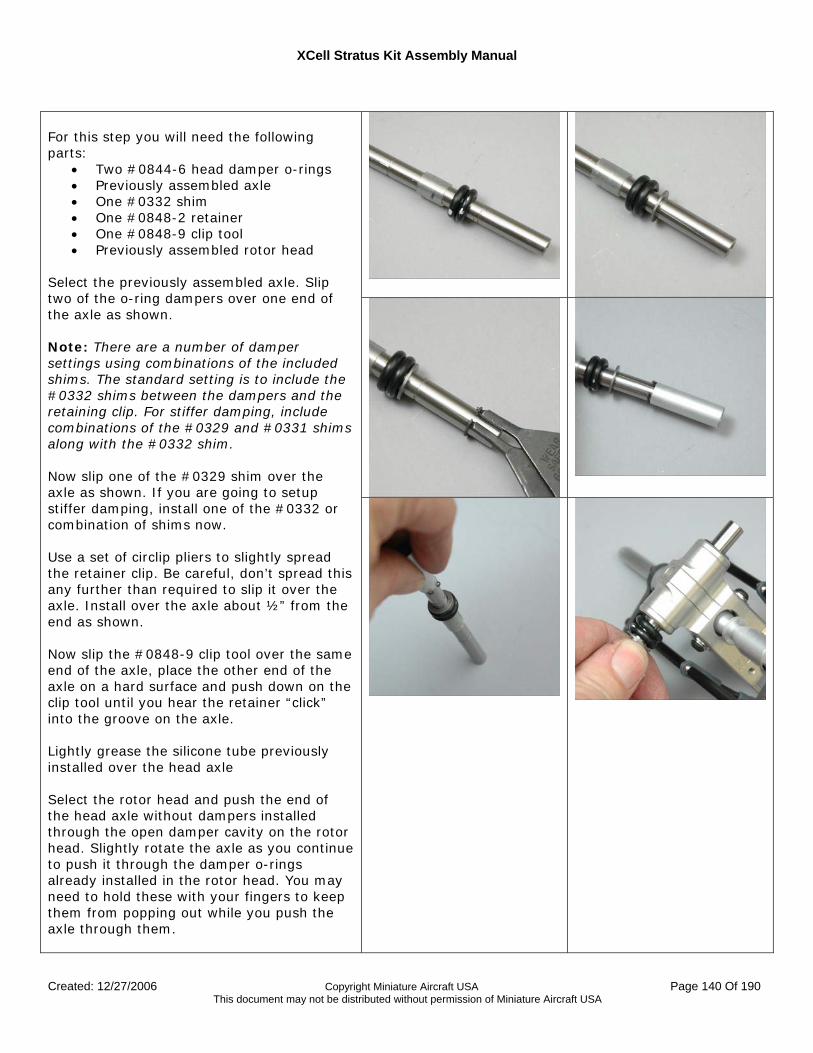
XCell Stratus Kit Assembly Manual
Created: 12/27/2006 Copyright Miniature Aircraft USA Page 140 Of 190 This document may not be distributed without permission of Miniature Aircraft USA
For this step you will need the following parts:
• Two #0844-6 head damper o-rings • Previously assembled axle • One #0332 shim • One #0848-2 retainer • One #0848-9 clip tool • Previously assembled rotor head
Select the previously assembled axle. Slip two of the o-ring dampers over one end of the axle as shown. Note: There are a number of damper settings using combinations of the included shims. The standard setting is to include the #0332 shims between the dampers and the retaining clip. For stiffer damping, include combinations of the #0329 and #0331 shims along with the #0332 shim. Now slip one of the #0329 shim over the axle as shown. If you are going to setup stiffer damping, install one of the #0332 or combination of shims now. Use a set of circlip pliers to slightly spread the retainer clip. Be careful, don’t spread this any further than required to slip it over the axle. Install over the axle about ½” from the end as shown. Now slip the #0848-9 clip tool over the same end of the axle, place the other end of the axle on a hard surface and push down on the clip tool until you hear the retainer “click” into the groove on the axle. Lightly grease the silicone tube previously installed over the head axle Select the rotor head and push the end of the head axle without dampers installed through the open damper cavity on the rotor head. Slightly rotate the axle as you continue to push it through the damper o-rings already installed in the rotor head. You may need to hold these with your fingers to keep them from popping out while you push the axle through them.
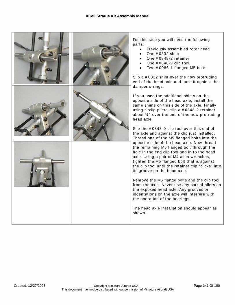
XCell Stratus Kit Assembly Manual
Created: 12/27/2006 Copyright Miniature Aircraft USA Page 141 Of 190 This document may not be distributed without permission of Miniature Aircraft USA
For this step you will need the following parts:
• Previously assembled rotor head • One #0332 shim • One #0848-2 retainer • One #0848-9 clip tool • Two #0086-1 flanged M5 bolts
Slip a #0332 shim over the now protruding end of the head axle and push it against the damper o-rings. If you used the additional shims on the opposite side of the head axle, install the same shims on this side of the axle. Finally using circlip pliers, slip a #0848-2 retainer about ½” over the end of the now protruding head axle. Slip the #0848-9 clip tool over this end of the axle and against the clip just installed. Thread one of the M5 flanged bolts into the opposite side of the head axle. Now thread the remaining M5 flanged bolt through the hole in the end clip tool and in to the head axle. Using a pair of M4 allen wrenches, tighten the M5 flanged bolt that is against the clip tool until the retainer clip “clicks” into its groove on the head axle. Remove the M5 flange bolts and the clip tool from the axle. Never use any sort of pliers on the exposed head axle. Any grooves or indentations on the axle will interfere with the operation of the bearings. The head axle installation should appear as shown.
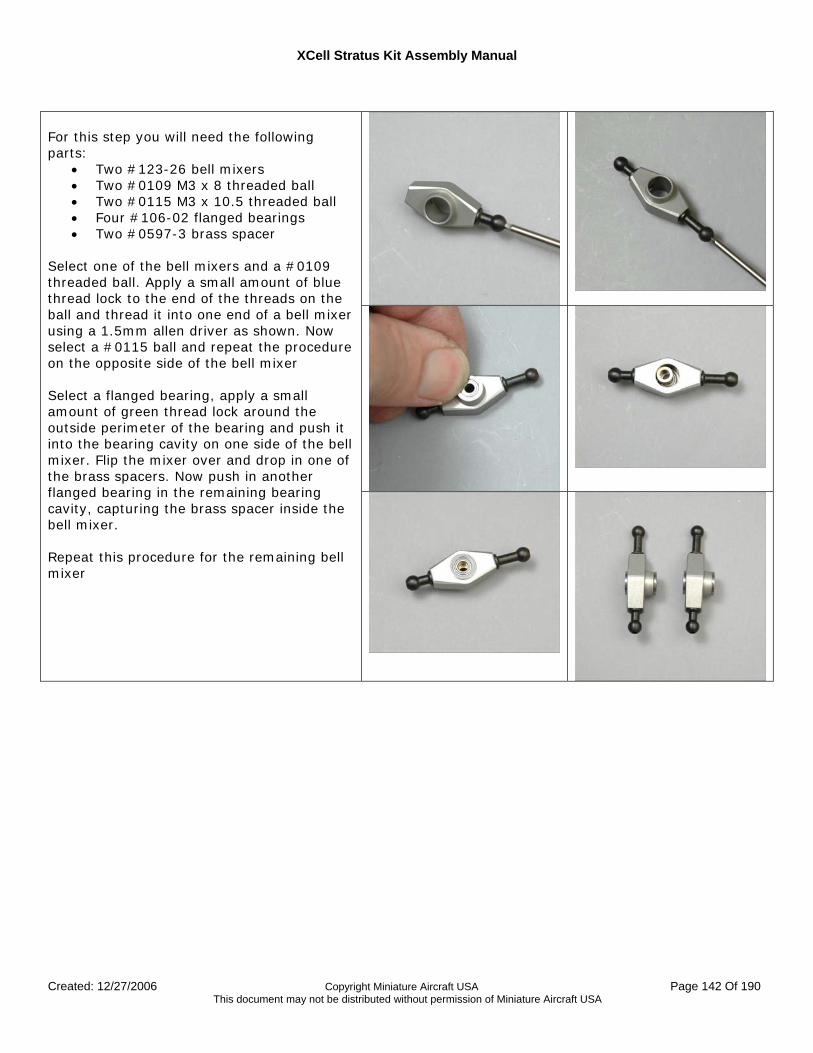
XCell Stratus Kit Assembly Manual
Created: 12/27/2006 Copyright Miniature Aircraft USA Page 142 Of 190 This document may not be distributed without permission of Miniature Aircraft USA
For this step you will need the following parts:
• Two #123-26 bell mixers • Two #0109 M3 x 8 threaded ball • Two #0115 M3 x 10.5 threaded ball • Four #106-02 flanged bearings • Two #0597-3 brass spacer
Select one of the bell mixers and a #0109 threaded ball. Apply a small amount of blue thread lock to the end of the threads on the ball and thread it into one end of a bell mixer using a 1.5mm allen driver as shown. Now select a #0115 ball and repeat the procedure on the opposite side of the bell mixer Select a flanged bearing, apply a small amount of green thread lock around the outside perimeter of the bearing and push it into the bearing cavity on one side of the bell mixer. Flip the mixer over and drop in one of the brass spacers. Now push in another flanged bearing in the remaining bearing cavity, capturing the brass spacer inside the bell mixer. Repeat this procedure for the remaining bell mixer
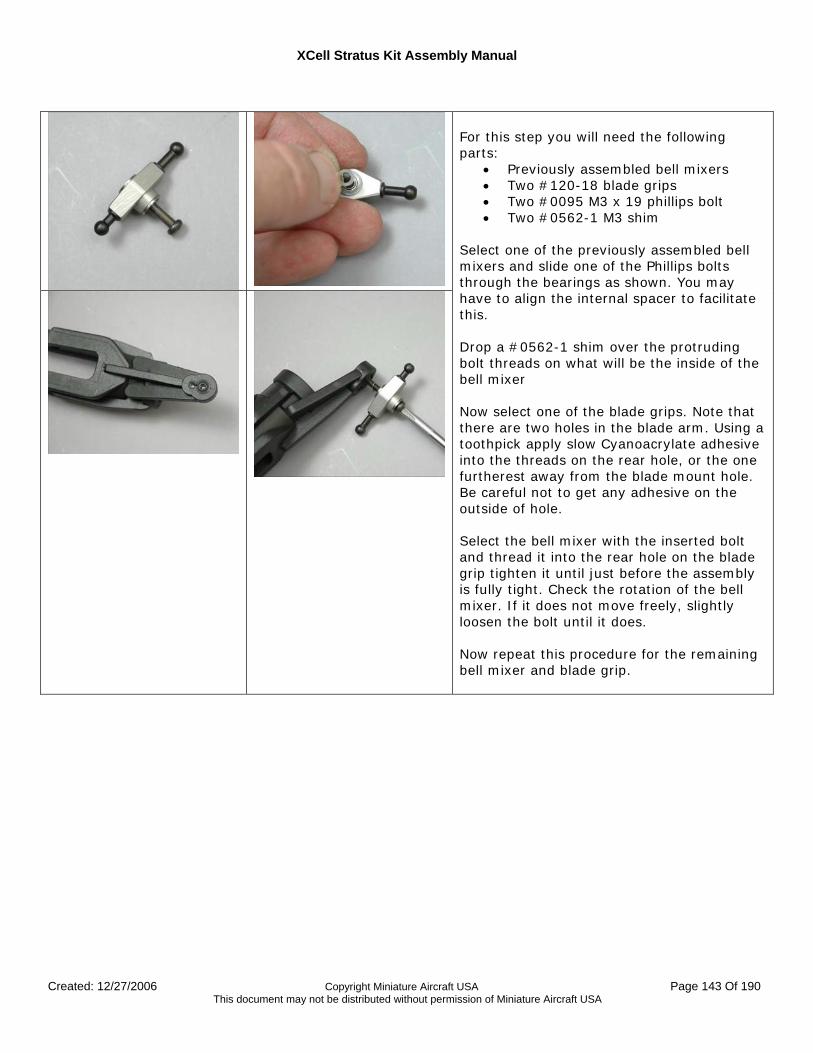
XCell Stratus Kit Assembly Manual
Created: 12/27/2006 Copyright Miniature Aircraft USA Page 143 Of 190 This document may not be distributed without permission of Miniature Aircraft USA
For this step you will need the following parts:
• Previously assembled bell mixers • Two #120-18 blade grips • Two #0095 M3 x 19 phillips bolt • Two #0562-1 M3 shim
Select one of the previously assembled bell mixers and slide one of the Phillips bolts through the bearings as shown. You may have to align the internal spacer to facilitate this. Drop a #0562-1 shim over the protruding bolt threads on what will be the inside of the bell mixer Now select one of the blade grips. Note that there are two holes in the blade arm. Using a toothpick apply slow Cyanoacrylate adhesive into the threads on the rear hole, or the one furtherest away from the blade mount hole. Be careful not to get any adhesive on the outside of hole. Select the bell mixer with the inserted bolt and thread it into the rear hole on the blade grip tighten it until just before the assembly is fully tight. Check the rotation of the bell mixer. If it does not move freely, slightly loosen the bolt until it does. Now repeat this procedure for the remaining bell mixer and blade grip.
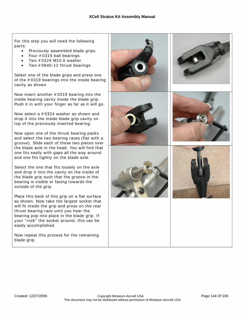
XCell Stratus Kit Assembly Manual
Created: 12/27/2006 Copyright Miniature Aircraft USA Page 144 Of 190 This document may not be distributed without permission of Miniature Aircraft USA
For this step you will need the following parts:
• Previously assembled blade grips • Four #0319 ball bearings • Two #0324 M10.6 washer • Two #0840-12 thrust bearings
Select one of the blade grips and press one of the #0319 bearings into the inside bearing cavity as shown Now insert another #0319 bearing into the inside bearing cavity inside the blade grip. Push it in with your finger as far as it will go. Now select a #0324 washer as shown and drop it into the inside blade grip cavity on top of the previously inserted bearing. Now open one of the thrust bearing packs and select the two bearing races (flat with a groove). Slide each of these two pieces over the blade axle in the head. You will find that one fits easily with gaps all the way around and one fits tightly on the blade axle. Select the one that fits loosely on the axle and drop it into the cavity on the inside of the blade grip such that the groove in the bearing is visible or facing towards the outside of the grip. Place this back of this grip on a flat surface as shown. Now take the largest socket that will fit inside the grip and press on the rear thrust bearing race until you hear the bearing pop into place in the blade grip. If your “rock” the socket around, this can be easily accomplished. Now repeat this process for the remaining blade grip.
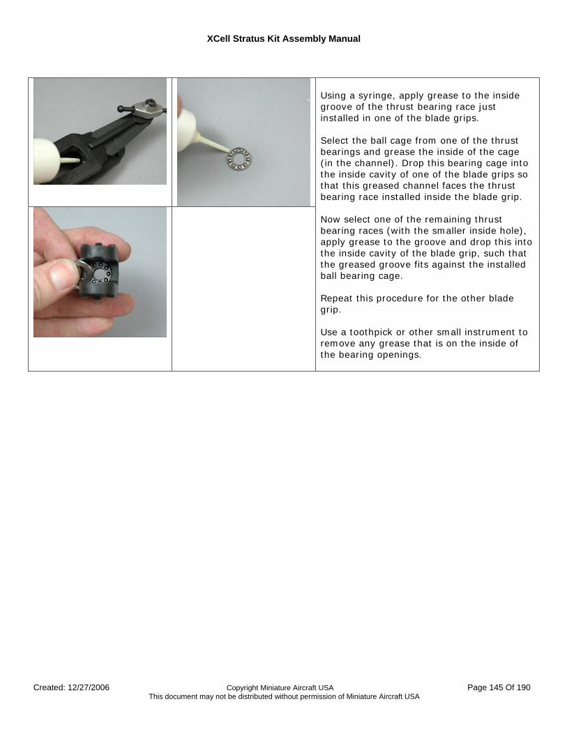
XCell Stratus Kit Assembly Manual
Created: 12/27/2006 Copyright Miniature Aircraft USA Page 145 Of 190 This document may not be distributed without permission of Miniature Aircraft USA
Using a syringe, apply grease to the inside groove of the thrust bearing race just installed in one of the blade grips. Select the ball cage from one of the thrust bearings and grease the inside of the cage (in the channel). Drop this bearing cage into the inside cavity of one of the blade grips so that this greased channel faces the thrust bearing race installed inside the blade grip. Now select one of the remaining thrust bearing races (with the smaller inside hole), apply grease to the groove and drop this into the inside cavity of the blade grip, such that the greased groove fits against the installed ball bearing cage. Repeat this procedure for the other blade grip. Use a toothpick or other small instrument to remove any grease that is on the inside of the bearing openings.
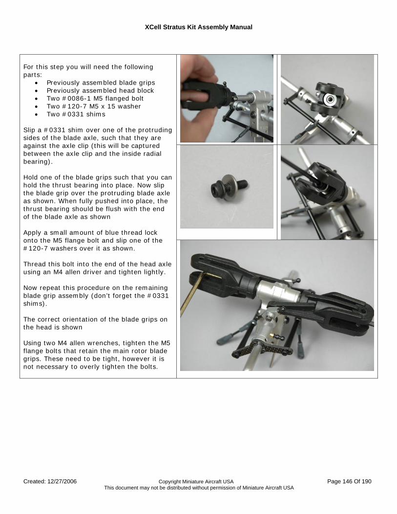
XCell Stratus Kit Assembly Manual
Created: 12/27/2006 Copyright Miniature Aircraft USA Page 146 Of 190 This document may not be distributed without permission of Miniature Aircraft USA
For this step you will need the following parts:
• Previously assembled blade grips • Previously assembled head block • Two #0086-1 M5 flanged bolt • Two #120-7 M5 x 15 washer • Two #0331 shims
Slip a #0331 shim over one of the protruding sides of the blade axle, such that they are against the axle clip (this will be captured between the axle clip and the inside radial bearing). Hold one of the blade grips such that you can hold the thrust bearing into place. Now slip the blade grip over the protruding blade axle as shown. When fully pushed into place, the thrust bearing should be flush with the end of the blade axle as shown Apply a small amount of blue thread lock onto the M5 flange bolt and slip one of the #120-7 washers over it as shown. Thread this bolt into the end of the head axle using an M4 allen driver and tighten lightly. Now repeat this procedure on the remaining blade grip assembly (don’t forget the #0331 shims). The correct orientation of the blade grips on the head is shown Using two M4 allen wrenches, tighten the M5 flange bolts that retain the main rotor blade grips. These need to be tight, however it is not necessary to overly tighten the bolts.
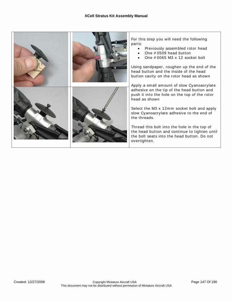
XCell Stratus Kit Assembly Manual
Created: 12/27/2006 Copyright Miniature Aircraft USA Page 147 Of 190 This document may not be distributed without permission of Miniature Aircraft USA
For this step you will need the following parts:
• Previously assembled rotor head • One #0509 head button • One #0065 M3 x 12 socket bolt
Using sandpaper, roughen up the end of the head button and the inside of the head button cavity on the rotor head as shown Apply a small amount of slow Cyanoacrylate adhesive on the tip of the head button and push it into the hole on the top of the rotor head as shown Select the M3 x 12mm socket bolt and apply slow Cyanoacrylate adhesive to the end of the threads. Thread this bolt into the hole in the top of the head button and continue to tighten until the bolt seats into the head button. Do not overtighten.
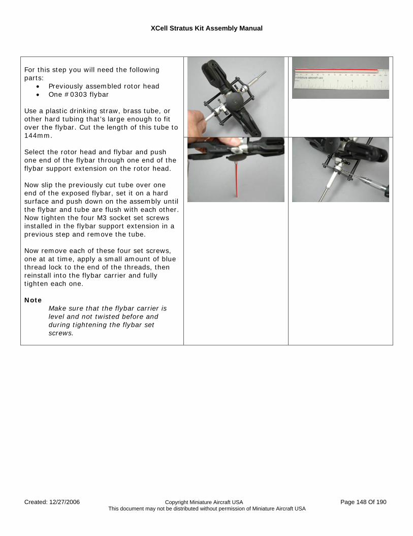
XCell Stratus Kit Assembly Manual
Created: 12/27/2006 Copyright Miniature Aircraft USA Page 148 Of 190 This document may not be distributed without permission of Miniature Aircraft USA
For this step you will need the following parts:
• Previously assembled rotor head • One #0303 flybar
Use a plastic drinking straw, brass tube, or other hard tubing that’s large enough to fit over the flybar. Cut the length of this tube to 144mm. Select the rotor head and flybar and push one end of the flybar through one end of the flybar support extension on the rotor head. Now slip the previously cut tube over one end of the exposed flybar, set it on a hard surface and push down on the assembly until the flybar and tube are flush with each other. Now tighten the four M3 socket set screws installed in the flybar support extension in a previous step and remove the tube. Now remove each of these four set screws, one at at time, apply a small amount of blue thread lock to the end of the threads, then reinstall into the flybar carrier and fully tighten each one. Note
Make sure that the flybar carrier is level and not twisted before and during tightening the flybar set screws.
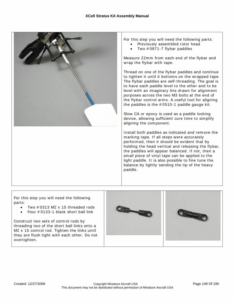
XCell Stratus Kit Assembly Manual
Created: 12/27/2006 Copyright Miniature Aircraft USA Page 149 Of 190 This document may not be distributed without permission of Miniature Aircraft USA
For this step you will need the following parts:
• Previously assembled rotor head • Two #0871-7 flybar paddles
Measure 22mm from each end of the flybar and wrap the flybar with tape. Thread on one of the flybar paddles and continue to tighten it until it bottoms on the wrapped tape. The flybar paddles are self-threading. The goal is to have each paddle level to the other and to be level with an imaginary line drawn for alignment purposes across the two M3 bolts at the end of the flybar control arms. A useful tool for aligning the paddles is the #0510-1 paddle gauge kit. Slow CA or epoxy is used as a paddle locking device, allowing sufficient cure time to simplify aligning the component. Install both paddles as indicated and remove the marking tape. If all steps were accurately performed, then it should be evident that by holding the head vertical and releasing the flybar, the paddles will appear balanced. If not, then a small piece of vinyl tape can be applied to the light paddle. It is also possible to fine tune the balance by lightly sanding the tip of the heavy paddle.
For this step you will need the following parts:
• Two #0313 M2 x 15 threaded rods • Four #0133-1 black short ball link
Construct two sets of control rods by threading two of the short ball links onto a M2 x 15 control rod. Tighten the links until they are flush tight with each other. Do not overtighten.
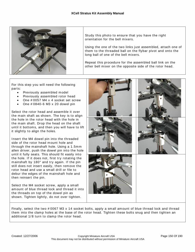
XCell Stratus Kit Assembly Manual
Created: 12/27/2006 Copyright Miniature Aircraft USA Page 150 Of 190 This document may not be distributed without permission of Miniature Aircraft USA
Study this photo to ensure that you have the right orientation for the bell mixers. Using the one of the two links just assembled, attach one of them to the threaded ball on the flybar pivot and onto the long ball of one of the bell mixers. Repeat this procedure for the assembled ball link on the other bell mixer on the opposite side of the rotor head.
For this step you will need the following parts:
• Previously assembled model • Previously assembled rotor head • One #0057 M4 x 4 socket set screw • One #0840-6 M3 x 20 dowel pin
Select the rotor head and assemble it over the main shaft as shown. The key is to align the hole in the rotor head with the hole in the main shaft. Drop the head on the shaft until it bottoms, and then you will have to lift it slightly to align the holes. Insert the M4 dowel pin into the threaded side of the rotor head mount hole and through the mainshaft hole. Using a 1.5mm allen driver, push the dowel pin into the hole until it fully seats. This should fit easily into the hole. If it does not, first try rotating the mainshaft by 180° and try again. If the pin still does not insert easily, then remove the rotor head and use a small drill or file to debur the edges of the mainshaft hole and then reinsert the pin. Select the M4 socket screw, apply a small amount of blue thread lock and thread it into the threads on top of the dowel pin as shown. Tighten lightly, do not over tighten.
Finally, select the two #0067 M3 x 14 socket bolts, apply a small amount of blue thread lock and thread them into the clamp holes at the base of the rotor head. Tighten these bolts snug and then tighten an additional 1/8 turn to clamp the rotor head.
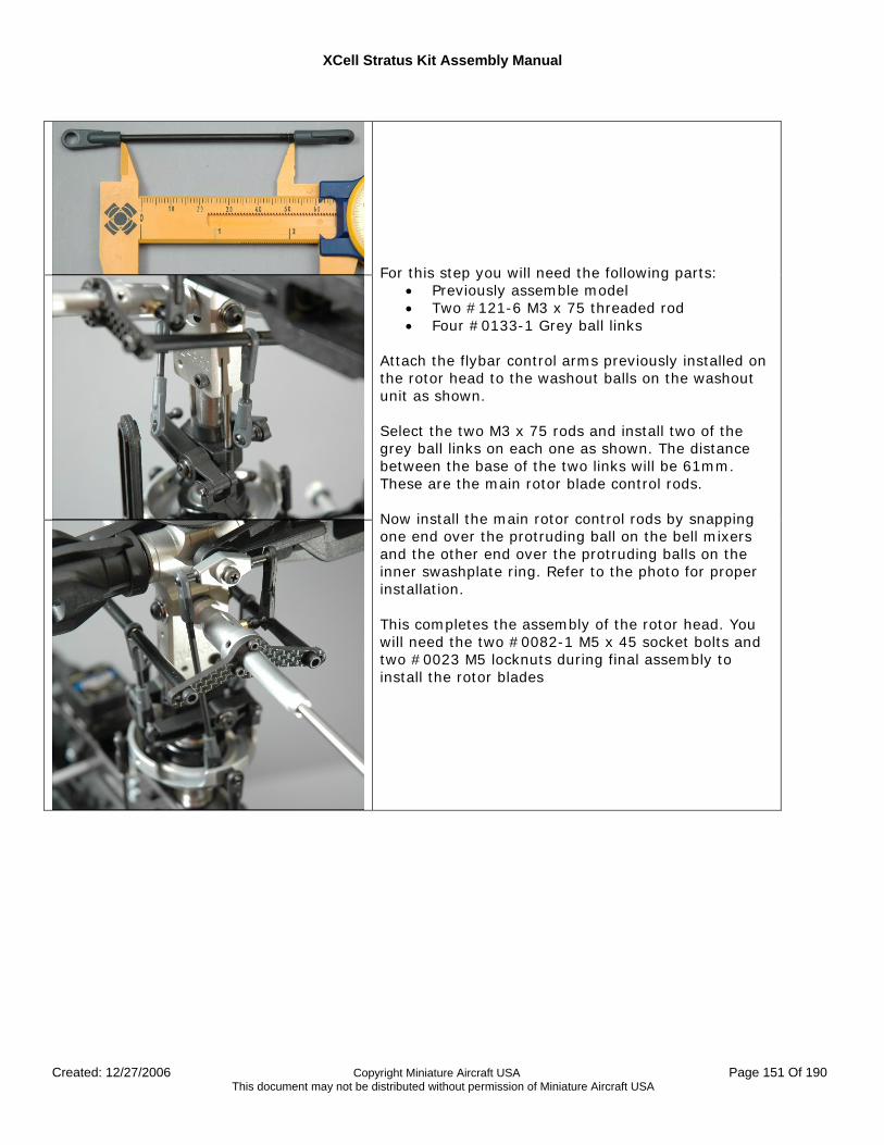
XCell Stratus Kit Assembly Manual
Created: 12/27/2006 Copyright Miniature Aircraft USA Page 151 Of 190 This document may not be distributed without permission of Miniature Aircraft USA
For this step you will need the following parts:
• Previously assemble model • Two #121-6 M3 x 75 threaded rod • Four #0133-1 Grey ball links
Attach the flybar control arms previously installed on the rotor head to the washout balls on the washout unit as shown. Select the two M3 x 75 rods and install two of the grey ball links on each one as shown. The distance between the base of the two links will be 61mm. These are the main rotor blade control rods. Now install the main rotor control rods by snapping one end over the protruding ball on the bell mixers and the other end over the protruding balls on the inner swashplate ring. Refer to the photo for proper installation. This completes the assembly of the rotor head. You will need the two #0082-1 M5 x 45 socket bolts and two #0023 M5 locknuts during final assembly to install the rotor blades
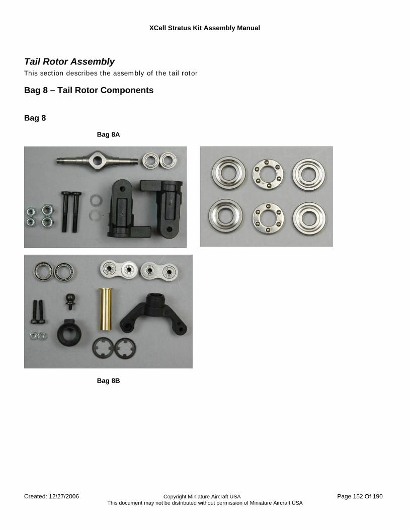
XCell Stratus Kit Assembly Manual
Created: 12/27/2006 Copyright Miniature Aircraft USA Page 152 Of 190 This document may not be distributed without permission of Miniature Aircraft USA
Tail Rotor Assembly This section describes the assembly of the tail rotor
Bag 8 – Tail Rotor Components Bag 8
Bag 8A
Bag 8B
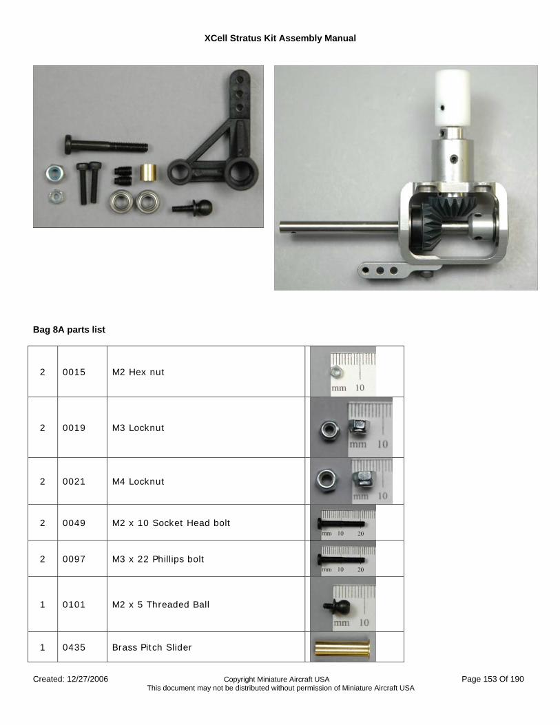
XCell Stratus Kit Assembly Manual
Created: 12/27/2006 Copyright Miniature Aircraft USA Page 153 Of 190 This document may not be distributed without permission of Miniature Aircraft USA
Bag 8A parts list
2 0015 M2 Hex nut
2 0019 M3 Locknut
2 0021 M4 Locknut
2 0049 M2 x 10 Socket Head bolt
2 0097 M3 x 22 Phillips bolt
1 0101 M2 x 5 Threaded Ball
1 0435 Brass Pitch Slider
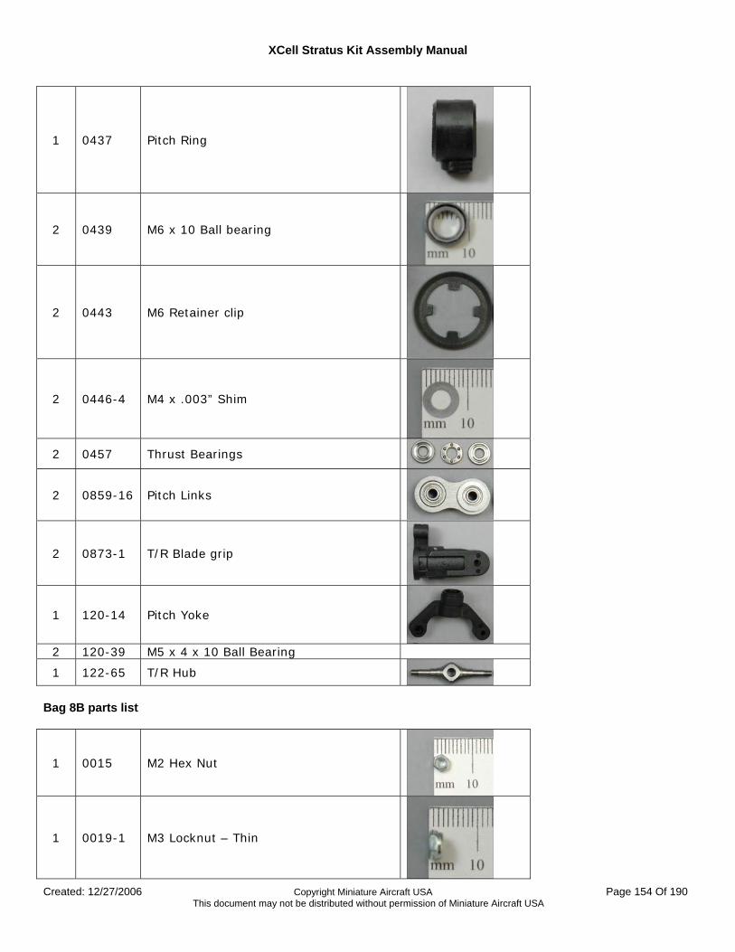
XCell Stratus Kit Assembly Manual
Created: 12/27/2006 Copyright Miniature Aircraft USA Page 154 Of 190 This document may not be distributed without permission of Miniature Aircraft USA
1 0437 Pitch Ring
2 0439 M6 x 10 Ball bearing
2 0443 M6 Retainer clip
2 0446-4 M4 x .003” Shim
2 0457 Thrust Bearings
2 0859-16 Pitch Links
2 0873-1 T/R Blade grip
1 120-14 Pitch Yoke
2 120-39 M5 x 4 x 10 Ball Bearing
1 122-65 T/R Hub
Bag 8B parts list
1 0015 M2 Hex Nut
1 0019-1 M3 Locknut – Thin
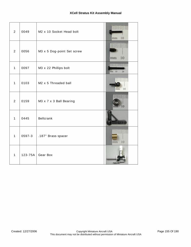
XCell Stratus Kit Assembly Manual
Created: 12/27/2006 Copyright Miniature Aircraft USA Page 155 Of 190 This document may not be distributed without permission of Miniature Aircraft USA
2 0049 M2 x 10 Socket Head bolt
2 0056 M3 x 5 Dog-point Set screw
1 0097 M3 x 22 Phillips bolt
1 0103 M2 x 5 Threaded ball
2 0159 M3 x 7 x 3 Ball Bearing
1 0445 Bellcrank
1 0597-3 .187” Brass spacer
1 123-75A Gear Box
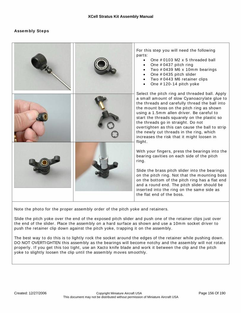
XCell Stratus Kit Assembly Manual
Created: 12/27/2006 Copyright Miniature Aircraft USA Page 156 Of 190 This document may not be distributed without permission of Miniature Aircraft USA
Assembly Steps
For this step you will need the following parts:
• One #0103 M2 x 5 threaded ball • One #0437 pitch ring • Two #0439 M6 x 10mm bearings • One #0435 pitch slider • Two #0443 M6 retainer clips • One #120-14 pitch yoke
Select the pitch ring and threaded ball. Apply a small amount of slow Cyanoacrylate glue to the threads and carefully thread the ball into the mount boss on the pitch ring as shown using a 1.5mm allen driver. Be careful to start the threads squarely on the plastic so the threads go in straight. Do not overtighten as this can cause the ball to strip the newly cut threads in the ring, which increases the risk that it might loosen in flight. With your fingers, press the bearings into the bearing cavities on each side of the pitch ring. Slide the brass pitch slider into the bearings on the pitch ring. Not that the mounting boss on the bottom of the pitch ring has a flat end and a round end. The pitch slider should be inserted into the ring on the same side as the flat end of the boss.
Note the photo for the proper assembly order of the pitch yoke and retainers. Slide the pitch yoke over the end of the exposed pitch slider and push one of the retainer clips just over the end of the slider. Place the assembly on a hard surface as shown and use a 10mm socket driver to push the retainer clip down against the pitch yoke, trapping it on the assembly. The best way to do this is to lightly rock the socket around the edges of the retainer while pushing down. DO NOT OVERTIGHTEN this assembly as the bearings will become notchy and the assembly will not rotate properly. If you get this too tight, use an Xacto knife blade and work it between the clip and the pitch yoke to slightly loosen the clip until the assembly moves smoothly.
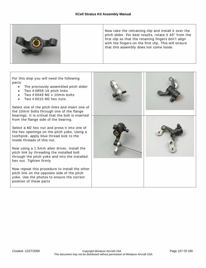
XCell Stratus Kit Assembly Manual
Created: 12/27/2006 Copyright Miniature Aircraft USA Page 157 Of 190 This document may not be distributed without permission of Miniature Aircraft USA
Now take the remaining clip and install it over the pitch slider. For best results, rotate it 45° from the first clip so that the retaining fingers don’t align with the fingers on the first clip. This will ensure that this assembly does not come loose.
For this step you will need the following parts:
• The previously assembled pitch slider • Two #0859-16 pitch links • Two #0049 M2 x 10mm bolts • Two #0015 M2 hex nuts
Select one of the pitch links and insert one of the 10mm bolts through one of the flange bearings. It is critical that the bolt is inserted from the flange side of the bearing. Select a M2 hex nut and press it into one of the hex openings on the pitch yoke. Using a toothpick, apply blue thread lock to the inside threads of this nut. Now using a 1.5mm allen driver, install the pitch link by threading the installed bolt through the pitch yoke and into the installed hex nut. Tighten firmly Now repeat this procedure to install the other pitch link on the opposite side of the pitch yoke. Use the photos to ensure the correct position of these parts
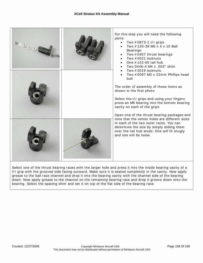
XCell Stratus Kit Assembly Manual
Created: 12/27/2006 Copyright Miniature Aircraft USA Page 158 Of 190 This document may not be distributed without permission of Miniature Aircraft USA
For this step you will need the following parts:
• Two #0873-1 t/r grips • Two #120-39 M5 x 4 x 10 Ball
Bearings • Two #0457 thrust bearings • Two #0021 locknuts • One #122-65 tail hub • Two 0446-4 M4 x .003” shim • Two #0019 locknuts • Two #0097 M3 x 22mm Phillips head
bolt The order of assembly of these items as shown in the first photo Select the t/r grips and using your fingers press an M5 bearing into the bottom bearing cavity on each of the grips Open one of the thrust bearing packages and note that the center holes are different sizes in each of the two outer races. You can determine the size by simply sliding them over the tail hub studs. One will fit snugly and one will be loose.
Select one of the thrust bearing races with the larger hole and press it into the inside bearing cavity of a t/r grip with the grooved side facing outward. Make sure it is seated completely in the cavity. Now apply grease to the ball race channel and drop it into the bearing cavity with the channel side of the bearing down. Now apply grease to the channel on the remaining bearing race and drop it groove down onto the bearing. Select the spacing shim and set it on top of the flat side of the bearing race.
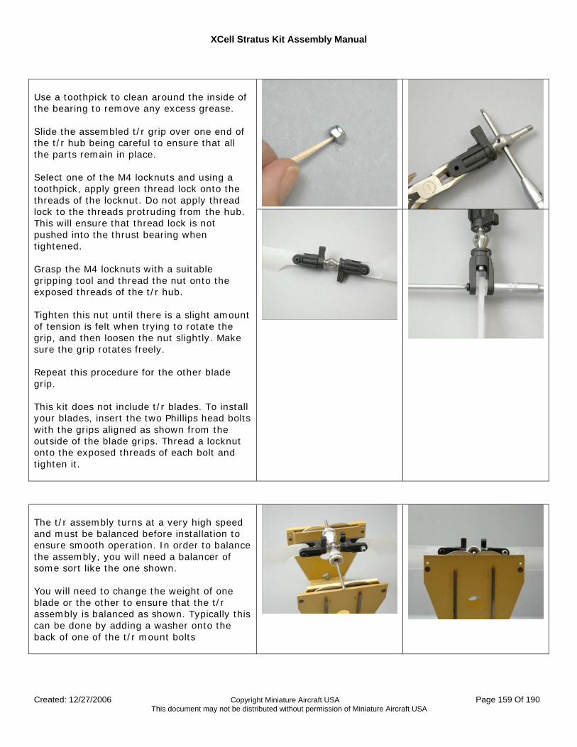
XCell Stratus Kit Assembly Manual
Created: 12/27/2006 Copyright Miniature Aircraft USA Page 159 Of 190 This document may not be distributed without permission of Miniature Aircraft USA
Use a toothpick to clean around the inside of the bearing to remove any excess grease. Slide the assembled t/r grip over one end of the t/r hub being careful to ensure that all the parts remain in place. Select one of the M4 locknuts and using a toothpick, apply green thread lock onto the threads of the locknut. Do not apply thread lock to the threads protruding from the hub. This will ensure that thread lock is not pushed into the thrust bearing when tightened. Grasp the M4 locknuts with a suitable gripping tool and thread the nut onto the exposed threads of the t/r hub. Tighten this nut until there is a slight amount of tension is felt when trying to rotate the grip, and then loosen the nut slightly. Make sure the grip rotates freely. Repeat this procedure for the other blade grip. This kit does not include t/r blades. To install your blades, insert the two Phillips head bolts with the grips aligned as shown from the outside of the blade grips. Thread a locknut onto the exposed threads of each bolt and tighten it.
The t/r assembly turns at a very high speed and must be balanced before installation to ensure smooth operation. In order to balance the assembly, you will need a balancer of some sort like the one shown. You will need to change the weight of one blade or the other to ensure that the t/r assembly is balanced as shown. Typically this can be done by adding a washer onto the back of one of the t/r mount bolts
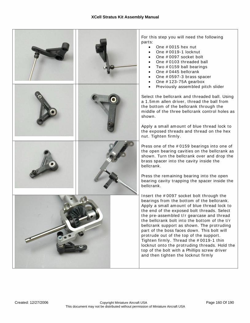
XCell Stratus Kit Assembly Manual
Created: 12/27/2006 Copyright Miniature Aircraft USA Page 160 Of 190 This document may not be distributed without permission of Miniature Aircraft USA
For this step you will need the following parts:
• One #0015 hex nut • One #0019-1 locknut • One #0097 socket bolt • One #0103 threaded ball • Two #0159 ball bearings • One #0445 bellcrank • One #0597-3 brass spacer • One #123-75A gearbox • Previously assembled pitch slider
Select the bellcrank and threaded ball. Using a 1.5mm allen driver, thread the ball from the bottom of the bellcrank through the middle of the three bellcrank control holes as shown. Apply a small amount of blue thread lock to the exposed threads and thread on the hex nut. Tighten firmly. Press one of the #0159 bearings into one of the open bearing cavities on the bellcrank as shown. Turn the bellcrank over and drop the brass spacer into the cavity inside the bellcrank. Press the remaining bearing into the open bearing cavity trapping the spacer inside the bellcrank. Insert the #0097 socket bolt through the bearings from the bottom of the bellcrank. Apply a small amount of blue thread lock to the end of the exposed bolt threads. Select the pre-assembled t/r gearcase and thread the bellcrank bolt into the bottom of the t/r bellcrank support as shown. The protruding part of the boss faces down. This bolt will protrude out of the top of the support. Tighten firmly. Thread the #0019-1 thin locknut onto the protruding threads. Hold the top of the bolt with a Phillips screw driver and then tighten the locknut firmly
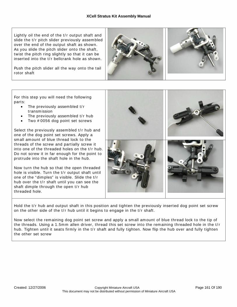
XCell Stratus Kit Assembly Manual
Created: 12/27/2006 Copyright Miniature Aircraft USA Page 161 Of 190 This document may not be distributed without permission of Miniature Aircraft USA
Lightly oil the end of the t/r output shaft and slide the t/r pitch slider previously assembled over the end of the output shaft as shown. As you slide the pitch slider onto the shaft, twist the pitch ring slightly so that it can be inserted into the t/r bellcrank hole as shown. Push the pitch slider all the way onto the tail rotor shaft
For this step you will need the following parts:
• The previously assembled t/r transmission
• The previously assembled t/r hub • Two #0056 dog point set screws
Select the previously assembled t/r hub and one of the dog point set screws. Apply a small amount of blue thread lock to the threads of the screw and partially screw it into one of the threaded holes on the t/r hub. Do not screw it in far enough for the point to protrude into the shaft hole in the hub. Now turn the hub so that the open threaded hole is visible. Turn the t/r output shaft until one of the “dimples” is visible. Slide the t/r hub over the t/r shaft until you can see the shaft dimple through the open t/r hub threaded hole.
Hold the t/r hub and output shaft in this position and tighten the previously inserted dog point set screw on the other side of the t/r hub until it begins to engage in the t/r shaft. Now select the remaining dog point set screw and apply a small amount of blue thread lock to the tip of the threads. Using a 1.5mm allen driver, thread this set screw into the remaining threaded hole in the t/r hub. Tighten until it seats firmly in the t/r shaft and fully tighten. Now flip the hub over and fully tighten the other set screw
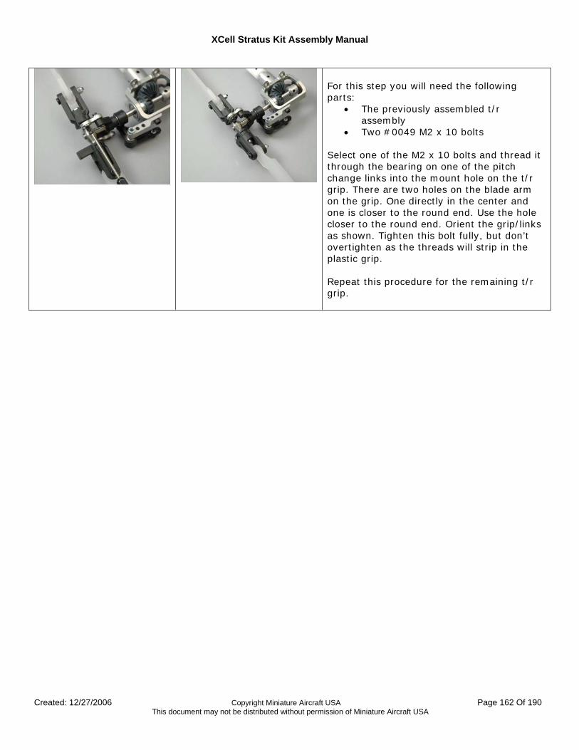
XCell Stratus Kit Assembly Manual
Created: 12/27/2006 Copyright Miniature Aircraft USA Page 162 Of 190 This document may not be distributed without permission of Miniature Aircraft USA
For this step you will need the following parts:
• The previously assembled t/r assembly
• Two #0049 M2 x 10 bolts Select one of the M2 x 10 bolts and thread it through the bearing on one of the pitch change links into the mount hole on the t/r grip. There are two holes on the blade arm on the grip. One directly in the center and one is closer to the round end. Use the hole closer to the round end. Orient the grip/links as shown. Tighten this bolt fully, but don’t overtighten as the threads will strip in the plastic grip. Repeat this procedure for the remaining t/r grip.
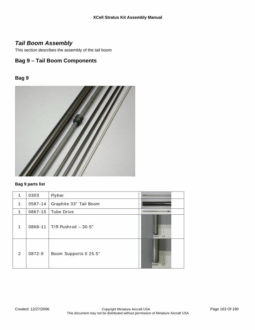
XCell Stratus Kit Assembly Manual
Created: 12/27/2006 Copyright Miniature Aircraft USA Page 163 Of 190 This document may not be distributed without permission of Miniature Aircraft USA
Tail Boom Assembly This section describes the assembly of the tail boom
Bag 9 – Tail Boom Components Bag 9
Bag 9 parts list
1 0303 Flybar
1 0587-14 Graphite 33” Tail Boom
1 0867-15 Tube Drive
1 0868-11 T/R Pushrod – 30.5”
2 0872-9 Boom Supports 0 25.5”
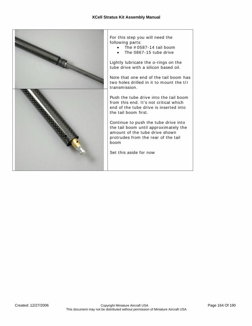
XCell Stratus Kit Assembly Manual
Created: 12/27/2006 Copyright Miniature Aircraft USA Page 164 Of 190 This document may not be distributed without permission of Miniature Aircraft USA
For this step you will need the following parts:
• The #0587-14 tail boom • The 0867-15 tube drive
Lightly lubricate the o-rings on the tube drive with a silicon based oil. Note that one end of the tail boom has two holes drilled in it to mount the t/r transmission. Push the tube drive into the tail boom from this end. It’s not critical which end of the tube drive is inserted into the tail boom first. Continue to push the tube drive into the tail boom until approximately the amount of the tube drive shown protrudes from the rear of the tail boom Set this aside for now
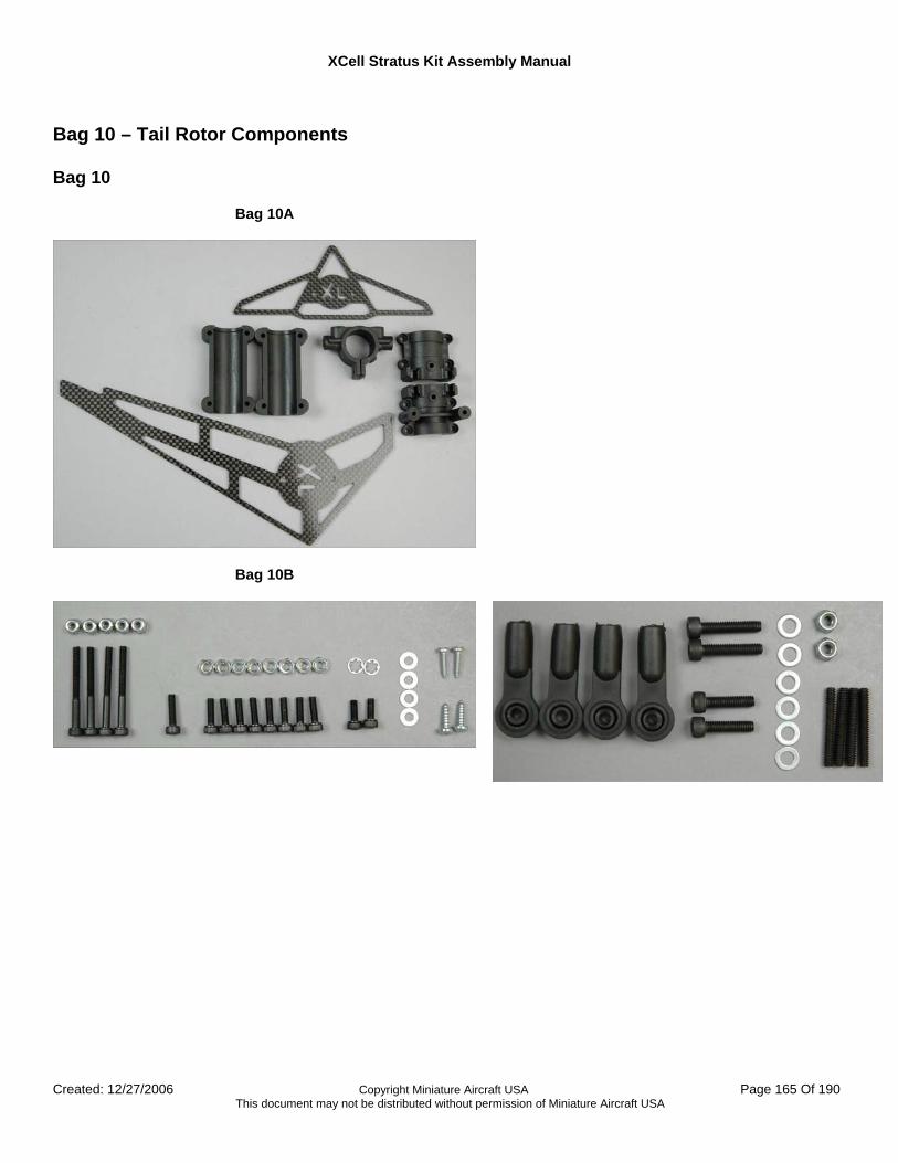
XCell Stratus Kit Assembly Manual
Created: 12/27/2006 Copyright Miniature Aircraft USA Page 165 Of 190 This document may not be distributed without permission of Miniature Aircraft USA
Bag 10 – Tail Rotor Components Bag 10
Bag 10A
Bag 10B
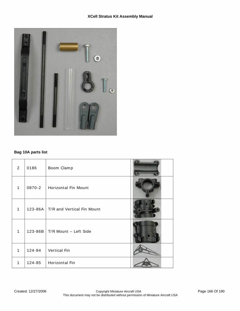
XCell Stratus Kit Assembly Manual
Created: 12/27/2006 Copyright Miniature Aircraft USA Page 166 Of 190 This document may not be distributed without permission of Miniature Aircraft USA
Bag 10A parts list
2 0186 Boom Clamp
1 0870-2 Horizontal Fin Mount
1 123-86A T/R and Vertical Fin Mount
1 123-86B T/R Mount – Left Side
1 124-84 Vertical Fin
1 124-85 Horizontal Fin
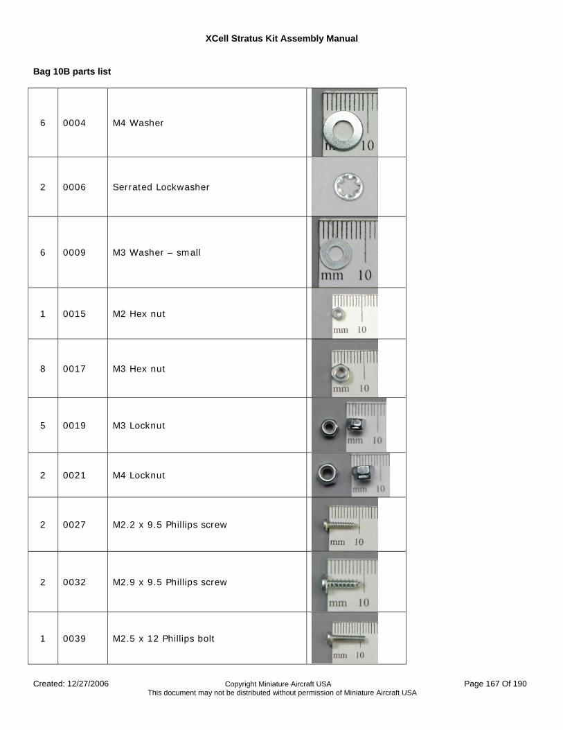
XCell Stratus Kit Assembly Manual
Created: 12/27/2006 Copyright Miniature Aircraft USA Page 167 Of 190 This document may not be distributed without permission of Miniature Aircraft USA
Bag 10B parts list
6 0004 M4 Washer
2 0006 Serrated Lockwasher
6 0009 M3 Washer – small
1 0015 M2 Hex nut
8 0017 M3 Hex nut
5 0019 M3 Locknut
2 0021 M4 Locknut
2 0027 M2.2 x 9.5 Phillips screw
2 0032 M2.9 x 9.5 Phillips screw
1 0039 M2.5 x 12 Phillips bolt
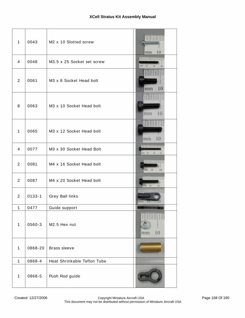
XCell Stratus Kit Assembly Manual
Created: 12/27/2006 Copyright Miniature Aircraft USA Page 168 Of 190 This document may not be distributed without permission of Miniature Aircraft USA
1 0043 M2 x 10 Slotted screw
4 0048 M3.5 x 25 Socket set screw
2 0061 M3 x 8 Socket Head bolt
8 0063 M3 x 10 Socket Head bolt
1 0065 M3 x 12 Socket Head bolt
4 0077 M3 x 30 Socket Head Bolt
2 0081 M4 x 16 Socket Head bolt
2 0087 M4 x 20 Socket Head bolt
2 0133-1 Grey Ball links
1 0477 Guide support
1 0560-3 M2.5 Hex nut
1 0868-20 Brass sleeve
1 0868-4 Heat Shrinkable Teflon Tube
1 0868-5 Push Rod guide
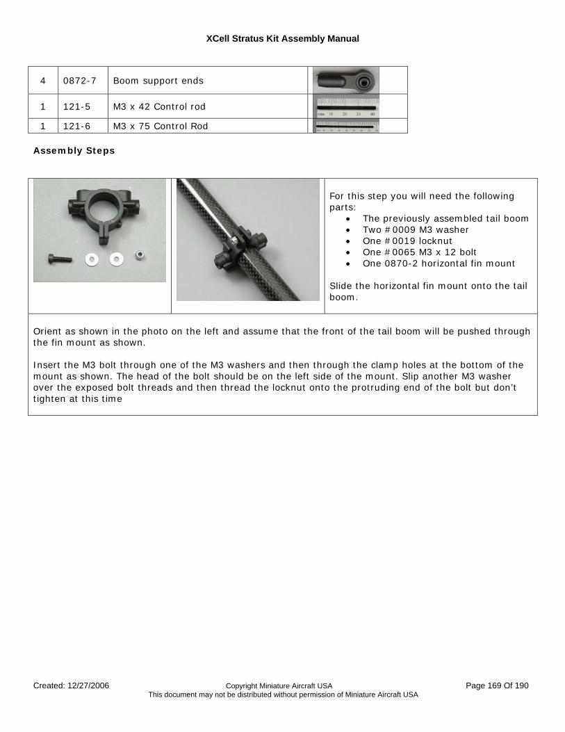
XCell Stratus Kit Assembly Manual
Created: 12/27/2006 Copyright Miniature Aircraft USA Page 169 Of 190 This document may not be distributed without permission of Miniature Aircraft USA
4 0872-7 Boom support ends
1 121-5 M3 x 42 Control rod
1 121-6 M3 x 75 Control Rod Assembly Steps
For this step you will need the following parts:
• The previously assembled tail boom • Two #0009 M3 washer • One #0019 locknut • One #0065 M3 x 12 bolt • One 0870-2 horizontal fin mount
Slide the horizontal fin mount onto the tail boom.
Orient as shown in the photo on the left and assume that the front of the tail boom will be pushed through the fin mount as shown. Insert the M3 bolt through one of the M3 washers and then through the clamp holes at the bottom of the mount as shown. The head of the bolt should be on the left side of the mount. Slip another M3 washer over the exposed bolt threads and then thread the locknut onto the protruding end of the bolt but don’t tighten at this time
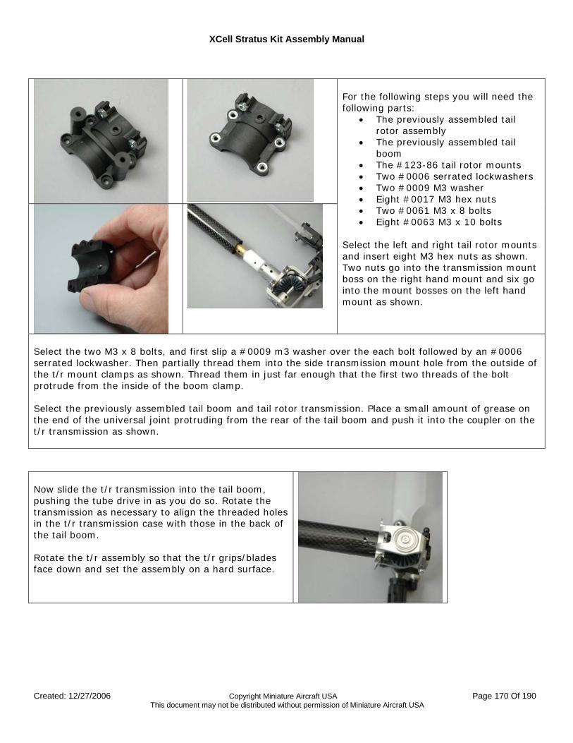
XCell Stratus Kit Assembly Manual
Created: 12/27/2006 Copyright Miniature Aircraft USA Page 170 Of 190 This document may not be distributed without permission of Miniature Aircraft USA
For the following steps you will need the following parts:
• The previously assembled tail rotor assembly
• The previously assembled tail boom
• The #123-86 tail rotor mounts • Two #0006 serrated lockwashers • Two #0009 M3 washer • Eight #0017 M3 hex nuts • Two #0061 M3 x 8 bolts • Eight #0063 M3 x 10 bolts
Select the left and right tail rotor mounts and insert eight M3 hex nuts as shown. Two nuts go into the transmission mount boss on the right hand mount and six go into the mount bosses on the left hand mount as shown.
Select the two M3 x 8 bolts, and first slip a #0009 m3 washer over the each bolt followed by an #0006 serrated lockwasher. Then partially thread them into the side transmission mount hole from the outside of the t/r mount clamps as shown. Thread them in just far enough that the first two threads of the bolt protrude from the inside of the boom clamp. Select the previously assembled tail boom and tail rotor transmission. Place a small amount of grease on the end of the universal joint protruding from the rear of the tail boom and push it into the coupler on the t/r transmission as shown. Now slide the t/r transmission into the tail boom, pushing the tube drive in as you do so. Rotate the transmission as necessary to align the threaded holes in the t/r transmission case with those in the back of the tail boom. Rotate the t/r assembly so that the t/r grips/blades face down and set the assembly on a hard surface.
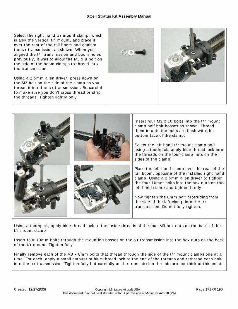
XCell Stratus Kit Assembly Manual
Created: 12/27/2006 Copyright Miniature Aircraft USA Page 171 Of 190 This document may not be distributed without permission of Miniature Aircraft USA
Select the right hand t/r mount clamp, which is also the vertical fin mount, and place it over the rear of the tail boom and against the t/r transmission as shown. When you aligned the t/r transmission and boom holes previously, it was to allow the M3 x 8 bolt on the side of the boom clamps to thread into the transmission. Using a 2.5mm allen driver, press down on the M3 bolt on the side of the clamp as you thread it into the t/r transmission. Be careful to make sure you don’t cross thread or strip the threads. Tighten lightly only
Insert four M3 x 10 bolts into the t/r mount clamp half bolt bosses as shown. Thread them in until the bolts are flush with the bottom face of the clamp. Select the left hand t/r mount clamp and using a toothpick, apply blue thread lock into the threads on the four clamp nuts on the sides of the clamp Place the left hand clamp over the rear of the tail boom, opposite of the installed right hand clamp. Using a 2.5mm allen driver to tighten the four 10mm bolts into the hex nuts on the left hand clamp and tighten firmly Now tighten the 8mm bolt protruding from the side of the left clamp into the t/r transmission. Do not fully tighten.
Using a toothpick, apply blue thread lock to the inside threads of the four M3 hex nuts on the back of the t/r mount clamp Insert four 10mm bolts through the mounting bosses on the t/r transmission into the hex nuts on the back of the t/r mount. Tighten fully Finally remove each of the M3 x 8mm bolts that thread through the side of the t/r mount clamps one at a time. For each, apply a small amount of blue thread lock to the end of the threads and rethread each bolt into the t/r transmission. Tighten fully but carefully as the transmission threads are not thick at this point

XCell Stratus Kit Assembly Manual
Created: 12/27/2006 Copyright Miniature Aircraft USA Page 172 Of 190 This document may not be distributed without permission of Miniature Aircraft USA
For this step you will need the following parts:
• The previously assembled tail boom assembly
• The #124-85 horizontal fin • The #124-84 vertical fin • Two #0027 M2.2 Phillips screw • Two #0032 M2.9 Phillips screw
Select the two M2.9 screws, two small washers and the vertical fin. Attach the vertical fin to the right hand t/r transmission mount as shown. Fully tighten the screws using a Phillips head screwdriver Select the two M2.2 screws, two small washers and the horizontal fin. Attach the horizontal fin to the horizontal boom support fin as shown. The front of the triangular fin should point away from the t/r transmission. Fully tighten using a Phillips head screwdriver
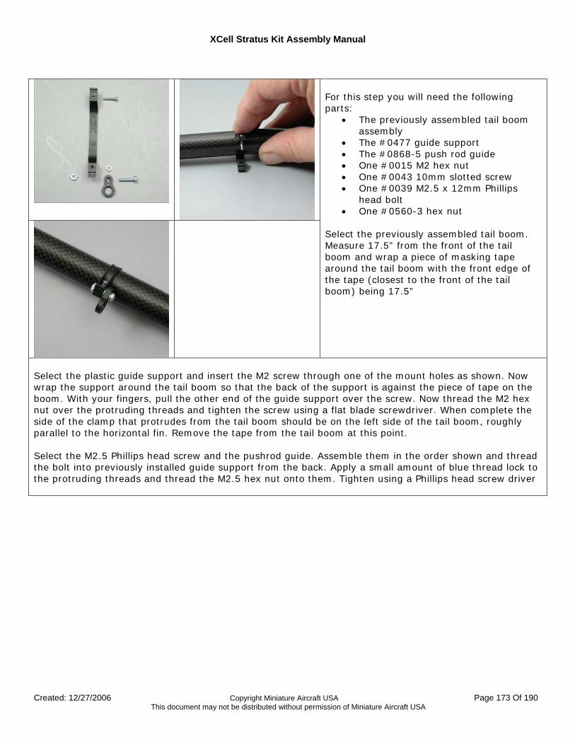
XCell Stratus Kit Assembly Manual
Created: 12/27/2006 Copyright Miniature Aircraft USA Page 173 Of 190 This document may not be distributed without permission of Miniature Aircraft USA
For this step you will need the following parts:
• The previously assembled tail boom assembly
• The #0477 guide support • The #0868-5 push rod guide • One #0015 M2 hex nut • One #0043 10mm slotted screw • One #0039 M2.5 x 12mm Phillips
head bolt • One #0560-3 hex nut
Select the previously assembled tail boom. Measure 17.5” from the front of the tail boom and wrap a piece of masking tape around the tail boom with the front edge of the tape (closest to the front of the tail boom) being 17.5”
Select the plastic guide support and insert the M2 screw through one of the mount holes as shown. Now wrap the support around the tail boom so that the back of the support is against the piece of tape on the boom. With your fingers, pull the other end of the guide support over the screw. Now thread the M2 hex nut over the protruding threads and tighten the screw using a flat blade screwdriver. When complete the side of the clamp that protrudes from the tail boom should be on the left side of the tail boom, roughly parallel to the horizontal fin. Remove the tape from the tail boom at this point. Select the M2.5 Phillips head screw and the pushrod guide. Assemble them in the order shown and thread the bolt into previously installed guide support from the back. Apply a small amount of blue thread lock to the protruding threads and thread the M2.5 hex nut onto them. Tighten using a Phillips head screw driver
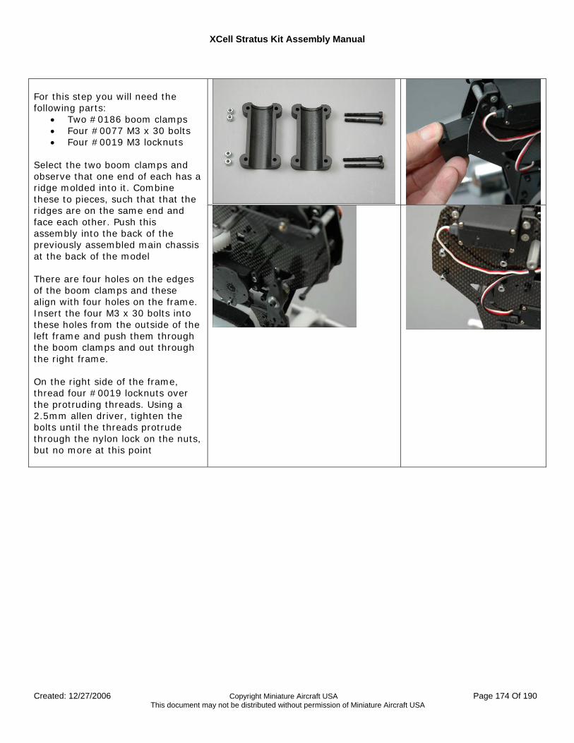
XCell Stratus Kit Assembly Manual
Created: 12/27/2006 Copyright Miniature Aircraft USA Page 174 Of 190 This document may not be distributed without permission of Miniature Aircraft USA
For this step you will need the following parts:
• Two #0186 boom clamps • Four #0077 M3 x 30 bolts • Four #0019 M3 locknuts
Select the two boom clamps and observe that one end of each has a ridge molded into it. Combine these to pieces, such that that the ridges are on the same end and face each other. Push this assembly into the back of the previously assembled main chassis at the back of the model There are four holes on the edges of the boom clamps and these align with four holes on the frame. Insert the four M3 x 30 bolts into these holes from the outside of the left frame and push them through the boom clamps and out through the right frame. On the right side of the frame, thread four #0019 locknuts over the protruding threads. Using a 2.5mm allen driver, tighten the bolts until the threads protrude through the nylon lock on the nuts, but no more at this point
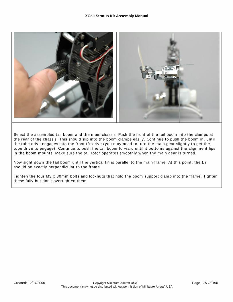
XCell Stratus Kit Assembly Manual
Created: 12/27/2006 Copyright Miniature Aircraft USA Page 175 Of 190 This document may not be distributed without permission of Miniature Aircraft USA
Select the assembled tail boom and the main chassis. Push the front of the tail boom into the clamps at the rear of the chassis. This should slip into the boom clamps easily. Continue to push the boom in, until the tube drive engages into the front t/r drive (you may need to turn the main gear slightly to get the tube drive to engage). Continue to push the tail boom forward until it bottoms against the alignment lips in the boom mounts. Make sure the tail rotor operates smoothly when the main gear is turned. Now sight down the tail boom until the vertical fin is parallel to the main frame. At this point, the t/r should be exactly perpendicular to the frame. Tighten the four M3 x 30mm bolts and locknuts that hold the boom support clamp into the frame. Tighten these fully but don’t overtighten them
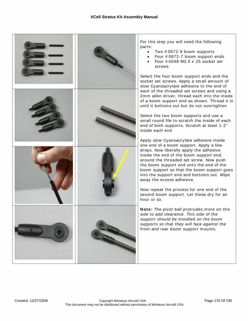
XCell Stratus Kit Assembly Manual
Created: 12/27/2006 Copyright Miniature Aircraft USA Page 176 Of 190 This document may not be distributed without permission of Miniature Aircraft USA
For this step you will need the following parts:
• Two #0872-9 boom supports • Four #0872-7 boom support ends • Four #0048 M3.5 x 25 socket set
screws Select the four boom support ends and the socket set screws. Apply a small amount of slow Cyanoacrylate adhesive to the end of each of the threaded set screws and using a 2mm allen driver, thread each into the inside of a boom support end as shown. Thread it in until it bottoms out but do not overtighten Select the two boom supports and use a small round file to scratch the inside of each end of both supports. Scratch at least 1-2” inside each end Apply slow Cyanoacrylate adhesive inside one end of a boom support. Apply a few drops. Now liberally apply the adhesive inside the end of the boom support end, around the threaded set screw. Now push the boom support end onto the end of the boom support so that the boom support goes into the support end and bottoms out. Wipe away the excess adhesive. Now repeat the process for one end of the second boom support. Let these dry for an hour or so. Note: The pivot ball protrudes more on this side to add clearance. This side of the support should be installed on the boom supports so that they will face against the front and rear boom support mounts.
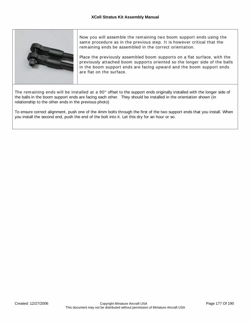
XCell Stratus Kit Assembly Manual
Created: 12/27/2006 Copyright Miniature Aircraft USA Page 177 Of 190 This document may not be distributed without permission of Miniature Aircraft USA
Now you will assemble the remaining two boom support ends using the same procedure as in the previous step. It is however critical that the remaining ends be assembled in the correct orientation. Place the previously assembled boom supports on a flat surface, with the previously attached boom supports oriented so the longer side of the balls in the boom support ends are facing upward and the boom support ends are flat on the surface.
The remaining ends will be installed at a 90° offset to the support ends originally installed with the longer side of the balls in the boom support ends are facing each other. They should be installed in the orientation shown (in relationship to the other ends in the previous photo) To ensure correct alignment, push one of the 4mm bolts through the first of the two support ends that you install. When you install the second end, push the end of the bolt into it. Let this dry for an hour or so.
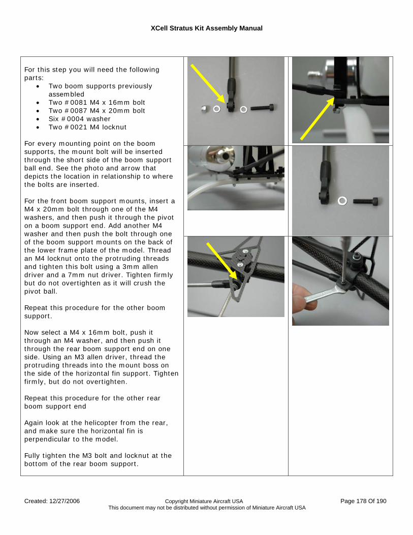
XCell Stratus Kit Assembly Manual
Created: 12/27/2006 Copyright Miniature Aircraft USA Page 178 Of 190 This document may not be distributed without permission of Miniature Aircraft USA
For this step you will need the following parts:
• Two boom supports previously assembled
• Two #0081 M4 x 16mm bolt • Two #0087 M4 x 20mm bolt • Six #0004 washer • Two #0021 M4 locknut
For every mounting point on the boom supports, the mount bolt will be inserted through the short side of the boom support ball end. See the photo and arrow that depicts the location in relationship to where the bolts are inserted. For the front boom support mounts, insert a M4 x 20mm bolt through one of the M4 washers, and then push it through the pivot on a boom support end. Add another M4 washer and then push the bolt through one of the boom support mounts on the back of the lower frame plate of the model. Thread an M4 locknut onto the protruding threads and tighten this bolt using a 3mm allen driver and a 7mm nut driver. Tighten firmly but do not overtighten as it will crush the pivot ball. Repeat this procedure for the other boom support. Now select a M4 x 16mm bolt, push it through an M4 washer, and then push it through the rear boom support end on one side. Using an M3 allen driver, thread the protruding threads into the mount boss on the side of the horizontal fin support. Tighten firmly, but do not overtighten. Repeat this procedure for the other rear boom support end Again look at the helicopter from the rear, and make sure the horizontal fin is perpendicular to the model. Fully tighten the M3 bolt and locknut at the bottom of the rear boom support.
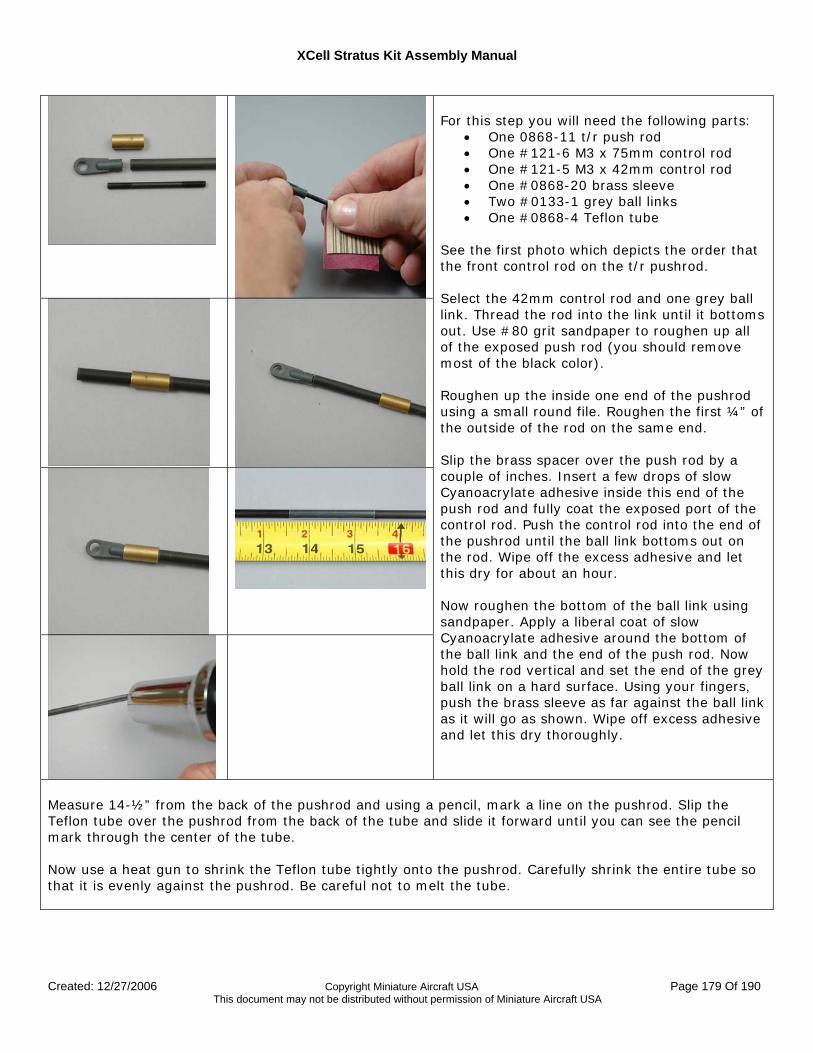
XCell Stratus Kit Assembly Manual
Created: 12/27/2006 Copyright Miniature Aircraft USA Page 179 Of 190 This document may not be distributed without permission of Miniature Aircraft USA
For this step you will need the following parts:
• One 0868-11 t/r push rod • One #121-6 M3 x 75mm control rod • One #121-5 M3 x 42mm control rod • One #0868-20 brass sleeve • Two #0133-1 grey ball links • One #0868-4 Teflon tube
See the first photo which depicts the order that the front control rod on the t/r pushrod. Select the 42mm control rod and one grey ball link. Thread the rod into the link until it bottoms out. Use #80 grit sandpaper to roughen up all of the exposed push rod (you should remove most of the black color). Roughen up the inside one end of the pushrod using a small round file. Roughen the first ¼” of the outside of the rod on the same end. Slip the brass spacer over the push rod by a couple of inches. Insert a few drops of slow Cyanoacrylate adhesive inside this end of the push rod and fully coat the exposed port of the control rod. Push the control rod into the end of the pushrod until the ball link bottoms out on the rod. Wipe off the excess adhesive and let this dry for about an hour. Now roughen the bottom of the ball link using sandpaper. Apply a liberal coat of slow Cyanoacrylate adhesive around the bottom of the ball link and the end of the push rod. Now hold the rod vertical and set the end of the grey ball link on a hard surface. Using your fingers, push the brass sleeve as far against the ball link as it will go as shown. Wipe off excess adhesive and let this dry thoroughly.
Measure 14-½” from the back of the pushrod and using a pencil, mark a line on the pushrod. Slip the Teflon tube over the pushrod from the back of the tube and slide it forward until you can see the pencil mark through the center of the tube. Now use a heat gun to shrink the Teflon tube tightly onto the pushrod. Carefully shrink the entire tube so that it is evenly against the pushrod. Be careful not to melt the tube.
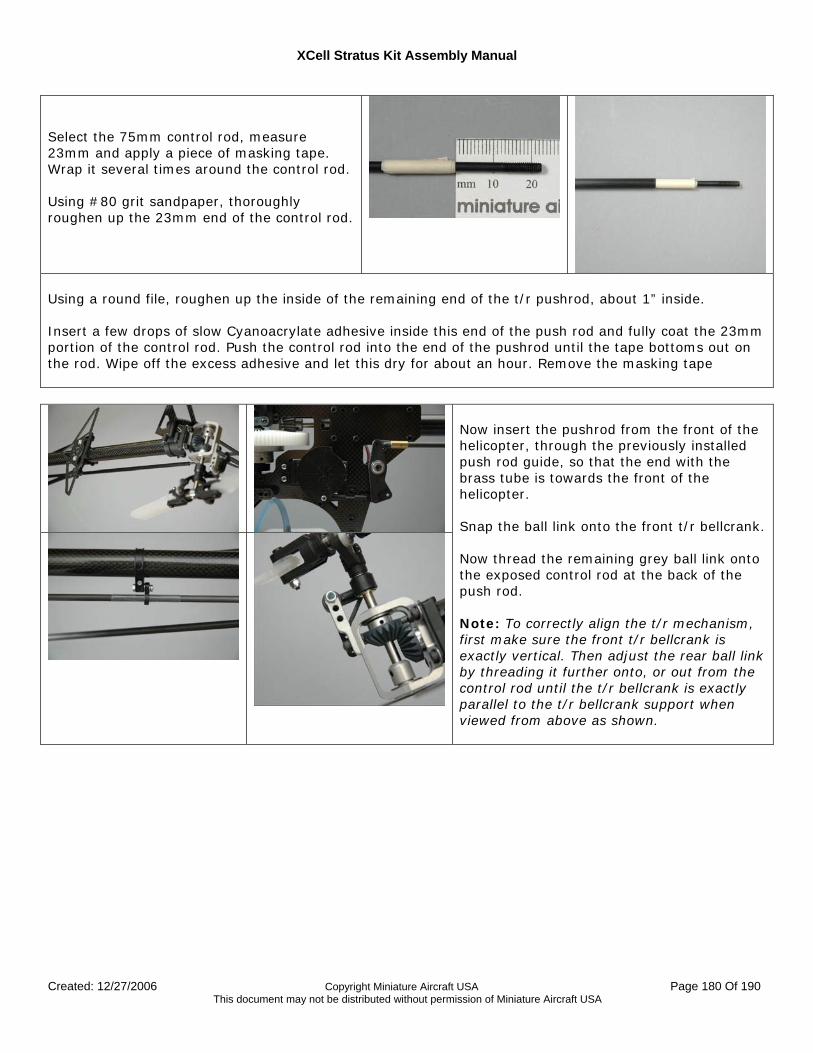
XCell Stratus Kit Assembly Manual
Created: 12/27/2006 Copyright Miniature Aircraft USA Page 180 Of 190 This document may not be distributed without permission of Miniature Aircraft USA
Select the 75mm control rod, measure 23mm and apply a piece of masking tape. Wrap it several times around the control rod. Using #80 grit sandpaper, thoroughly roughen up the 23mm end of the control rod.
Using a round file, roughen up the inside of the remaining end of the t/r pushrod, about 1” inside. Insert a few drops of slow Cyanoacrylate adhesive inside this end of the push rod and fully coat the 23mm portion of the control rod. Push the control rod into the end of the pushrod until the tape bottoms out on the rod. Wipe off the excess adhesive and let this dry for about an hour. Remove the masking tape
Now insert the pushrod from the front of the helicopter, through the previously installed push rod guide, so that the end with the brass tube is towards the front of the helicopter. Snap the ball link onto the front t/r bellcrank. Now thread the remaining grey ball link onto the exposed control rod at the back of the push rod. Note: To correctly align the t/r mechanism, first make sure the front t/r bellcrank is exactly vertical. Then adjust the rear ball link by threading it further onto, or out from the control rod until the t/r bellcrank is exactly parallel to the t/r bellcrank support when viewed from above as shown.
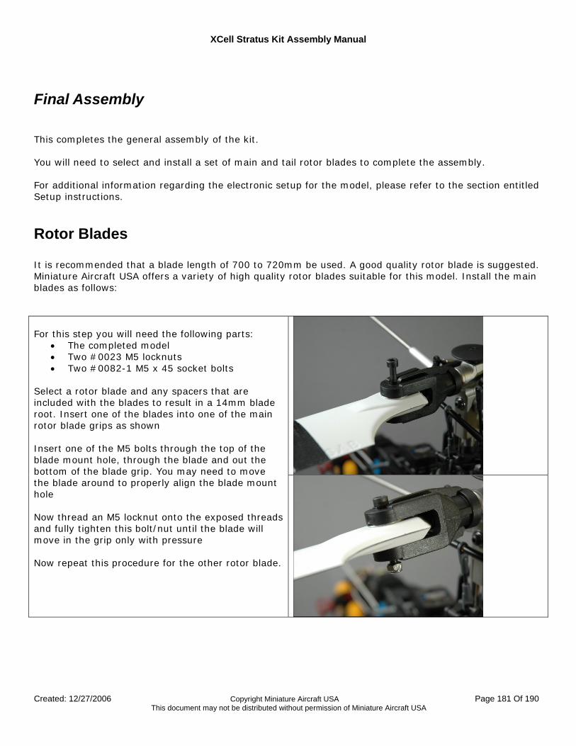
XCell Stratus Kit Assembly Manual
Created: 12/27/2006 Copyright Miniature Aircraft USA Page 181 Of 190 This document may not be distributed without permission of Miniature Aircraft USA
Final Assembly This completes the general assembly of the kit. You will need to select and install a set of main and tail rotor blades to complete the assembly. For additional information regarding the electronic setup for the model, please refer to the section entitled Setup instructions.
Rotor Blades It is recommended that a blade length of 700 to 720mm be used. A good quality rotor blade is suggested. Miniature Aircraft USA offers a variety of high quality rotor blades suitable for this model. Install the main blades as follows:
For this step you will need the following parts:
• The completed model • Two #0023 M5 locknuts • Two #0082-1 M5 x 45 socket bolts
Select a rotor blade and any spacers that are included with the blades to result in a 14mm blade root. Insert one of the blades into one of the main rotor blade grips as shown Insert one of the M5 bolts through the top of the blade mount hole, through the blade and out the bottom of the blade grip. You may need to move the blade around to properly align the blade mount hole Now thread an M5 locknut onto the exposed threads and fully tighten this bolt/nut until the blade will move in the grip only with pressure Now repeat this procedure for the other rotor blade.
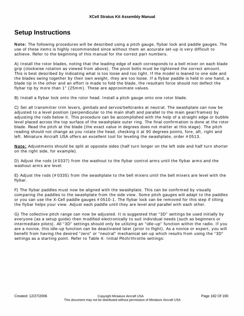
XCell Stratus Kit Assembly Manual
Created: 12/27/2006 Copyright Miniature Aircraft USA Page 182 Of 190 This document may not be distributed without permission of Miniature Aircraft USA
Setup Instructions
Note: The following procedures will be described using a pitch gauge, flybar lock and paddle gauges. The use of these items is highly recommended since without them an accurate set-up is very difficult to achieve. Refer to the beginning of this manual for the correct part numbers. A) Install the rotor blades, noting that the leading edge of each corresponds to a bell mixer on each blade grip (clockwise rotation as viewed from above). The pivot bolts must be tightened the correct amount. This is best described by indicating what is too loose and too tight. If the model is leaned to one side and the blades swing together by their own weight, they are too loose. If a flybar paddle is held in one hand, a blade tip in the other and an effort is made to fold the blade, the resultant force should not deflect the flybar tip by more than 1" (25mm). These are approximate values. B) Install a flybar lock onto the rotor head. Install a pitch gauge onto one rotor blade. C) Set all transmitter trim levers, gimbals and servos/bellcranks at neutral. The swashplate can now be adjusted to a level position (perpendicular to the main shaft and parallel to the main gear/frames) by adjusting the rods below it. This procedure can be accomplished with the help of a straight edge or bubble level placed across the top surface of the swashplate outer ring. The final confirmation is done at the rotor blade. Read the pitch at the blade (the exact value in degrees does not matter at this stage). The pitch reading should not change as you rotate the head, checking it at 90 degrees points, fore, aft, right and left. Miniature Aircraft USA offers an excellent tool for leveling the swashplate, order #0513. Note: Adjustments should be split at opposite sides (half turn longer on the left side and half turn shorter on the right side, for example). D) Adjust the rods (#0337) from the washout to the flybar control arms until the flybar arms and the washout arms are level. E) Adjust the rods (#0335) from the swashplate to the bell mixers until the bell mixers are level with the flybar. F) The flybar paddles must now be aligned with the swashplate. This can be confirmed by visually comparing the paddles to the swashplate from the side view. Some pitch gauges will adapt to the paddles or you can use the X-Cell paddle gauges #0510-1. The flybar lock can be removed for this step if tilting the flybar helps your view. Adjust each paddle until they are level and parallel with each other. G) The collective pitch range can now be adjusted. It is suggested that “3D” settings be used initially by everyone (as a setup guide) then modified electronically to suit individual needs (such as beginners or intermediate pilots). All “3D” settings should only be utilizing an “idle-up” function within the radio. If you are a novice, this idle-up function can be deactivated later (prior to flight). As a novice or expert, you will benefit from having the desired “zero” or “neutral” mechanical set-up which results from using the “3D” settings as a starting point. Refer to Table 4: Initial Pitch/throttle settings:
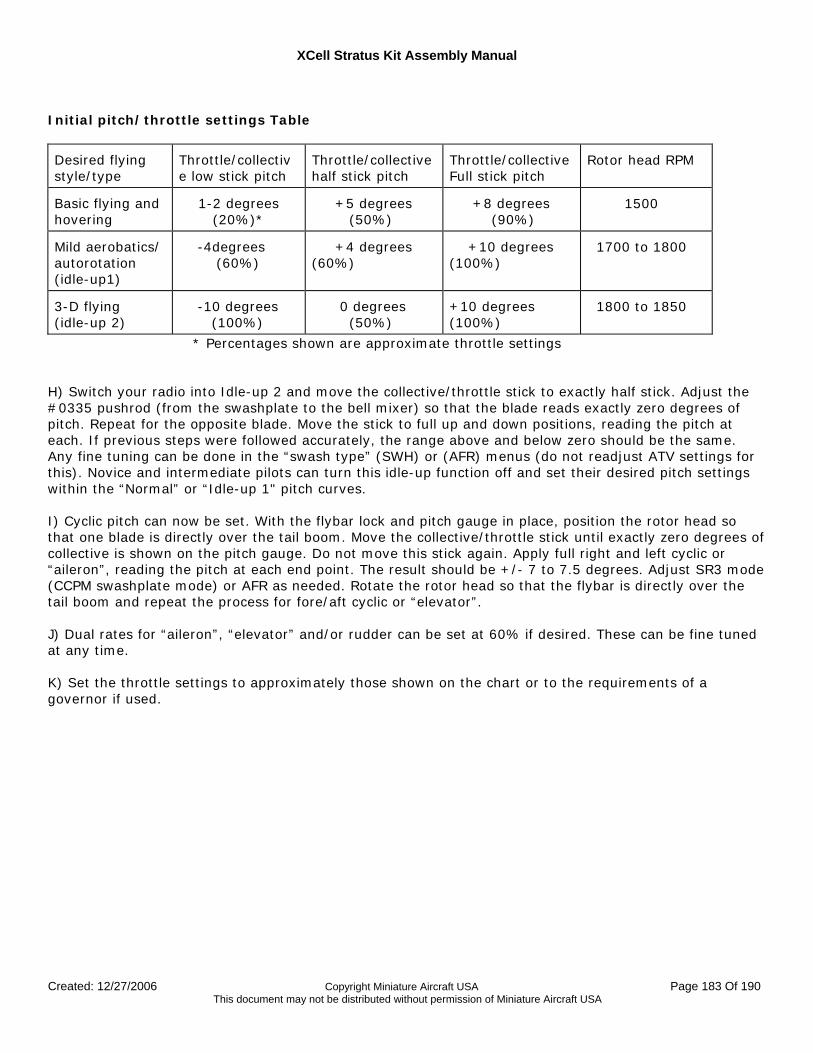
XCell Stratus Kit Assembly Manual
Created: 12/27/2006 Copyright Miniature Aircraft USA Page 183 Of 190 This document may not be distributed without permission of Miniature Aircraft USA
Initial pitch/throttle settings Table
Desired flying style/type
Throttle/collective low stick pitch
Throttle/collective half stick pitch
Throttle/collective Full stick pitch
Rotor head RPM
Basic flying and hovering
1-2 degrees (20%)*
+5 degrees (50%)
+8 degrees (90%)
1500
Mild aerobatics/ autorotation (idle-up1)
-4degrees (60%)
+4 degrees (60%)
+10 degrees (100%)
1700 to 1800
3-D flying (idle-up 2)
-10 degrees (100%)
0 degrees (50%)
+10 degrees (100%)
1800 to 1850
* Percentages shown are approximate throttle settings H) Switch your radio into Idle-up 2 and move the collective/throttle stick to exactly half stick. Adjust the #0335 pushrod (from the swashplate to the bell mixer) so that the blade reads exactly zero degrees of pitch. Repeat for the opposite blade. Move the stick to full up and down positions, reading the pitch at each. If previous steps were followed accurately, the range above and below zero should be the same. Any fine tuning can be done in the “swash type” (SWH) or (AFR) menus (do not readjust ATV settings for this). Novice and intermediate pilots can turn this idle-up function off and set their desired pitch settings within the “Normal” or “Idle-up 1" pitch curves. I) Cyclic pitch can now be set. With the flybar lock and pitch gauge in place, position the rotor head so that one blade is directly over the tail boom. Move the collective/throttle stick until exactly zero degrees of collective is shown on the pitch gauge. Do not move this stick again. Apply full right and left cyclic or “aileron”, reading the pitch at each end point. The result should be +/- 7 to 7.5 degrees. Adjust SR3 mode (CCPM swashplate mode) or AFR as needed. Rotate the rotor head so that the flybar is directly over the tail boom and repeat the process for fore/aft cyclic or “elevator”. J) Dual rates for “aileron”, “elevator” and/or rudder can be set at 60% if desired. These can be fine tuned at any time. K) Set the throttle settings to approximately those shown on the chart or to the requirements of a governor if used.
XCell Stratus Kit Assembly Manual
Created: 12/27/2006 Copyright Miniature Aircraft USA Page 184 Of 190 This document may not be distributed without permission of Miniature Aircraft USA
Final Inspection Recheck overall for loose fasteners, interfering components or incorrect radio installation. Operate all radio controls making certain that none are reversed and that the throttle can properly close the carburetor. Check to see that no control linkages are binding. Be certain that the gyro functions in the proper direction.
Pre-Flight Instructions At home:
• Be sure you have all necessary equipment to operate or service the model. Be sure all batteries are fully charged.
At the flying site:
• Observe any flying site rules. • Check the frequency board or any nearby pilots to be sure your frequency is clear. • Range check your radio as per your radio manufacturer’s instructions. • Pre-check all controls. • Obtain assistance from more experienced pilots if possible. • Never leave the transmitter in a position that would allow it to be handled or upset while you not
attending it...keep it cased when not in use. Starting the model:
• Check your battery status whenever possible. Most factory shipped batteries can only sustain three “full tank” flights on a charge. Do not take any unnecessary risks. Always turn off all components between flights.
XCell Stratus Kit Assembly Manual
Created: 12/27/2006 Copyright Miniature Aircraft USA Page 185 Of 190 This document may not be distributed without permission of Miniature Aircraft USA
Initial Trimming Instructions Throttle and pitch curves:
• After the needle valves are adjusted the model can be trimmed for hover. • The throttle curve should be adjusted so that the model is almost to the hover head speed just
above quarter stick. This helps the model lift off smoothly and also allows you to do slow vertical descents without fear of the engine running too slow.
• The throttle curve above half stick should be adjusted so that slow vertical ascents can be made without the engine speeding up or slowing down.
• Simultaneously adjust the hover pitch and hover throttle for the desired hovering rpm at half stick. • Next, adjust the high and low side of the normal pitch curve until the model has the response you
want in a hover. Tail rotor trimming:
• Adjust tail rotor trim as per your gyro instructions. Tail rotor compensation for torque: Note: Not required if you are using a heading lock type gyro and never intend to switch out of that mode.
• All adjustments are made from hover (at least 15' in altitude) with a “trimmed” tail rotor. • When properly adjusted, the model should not rotate to the right or left when ascending or
descending. • See your radio manufacturer’s instruction manual.
Swashplate trimming:
• When the helicopter drifts to the left or right, adjust the “aileron” transmitter trimmer until stabilized.
• When the helicopter drifts forward or backwards, adjust the “elevator” trimmer until stabilized. Main rotor dynamic blade tracking:
• The tracking of the main rotor blades may be checked just prior to lift off. • Be sure to maintain a safe distance from the machine. • The adjustments can be made by changing the length of the hiller rod (#0335) on either side of
the head. • A piece of colored tape may be applied to one blade tip in order to visually determine which blade
is high or low. Tracking procedure: -Low blade speed >>Lower the high blade -High blade speed >>Raise the low blade -If blades are out of track ½" or more >>Recheck original pitch settings
XCell Stratus Kit Assembly Manual
Created: 12/27/2006 Copyright Miniature Aircraft USA Page 186 Of 190 This document may not be distributed without permission of Miniature Aircraft USA
Maintenance Items
Open Tail Rotor Transmission
For best results when using the Open Tail Rotor transmission, it is important that you pay attention to two areas:
• T/R Transmission Gear Mesh • T/R Radio and Gyro Setup
Open T/R Transmission Gear Mesh
As delivered, the Open T/R transmission is properly meshed and has no backlash. However after as few as 1-2 gallons of use, the tail gears will show an increased amount of backlash (the actual time may vary depending on your flying style for this break-in period). As with any set of plastic gears, a large amount of backlash in the gear mesh can be detrimental during high stress maneuvers, so they will need to be adjusted. In addition, over time, additional adjustments may be necessary if the gears develop backlash. The adjustment process is very simple and is as follows: Open T/R Transmission Gear Mesh Adjustment Procedure:
1. Remove the gearbox from the tail boom clamp 2. Note the setscrews on the top and bottom of the transmission neck. Remove each, apply blue
thread lock to the screws and then re-thread them into the holes until each setscrew just bottoms out. Then loosen each approximately 1/8 of a turn
3. Tap the Delrin coupler inward until there is minimal backlash in the gear mesh with smooth operation. If the gears are meshed too deeply, a noticeable roughness in the gears will be felt.
4. Further tighten each setscrew until you feel them tough bottom. Alternately tighten each setscrew in small increments, approximately 1/16 of a turn each time. A snug fit of both set screws is all that is necessary. Make sure you applied blue thread lock to the setscrews NOTE: Over tightening of the setscrews will cause the bearings to pre-load and become notchy when rotated. This will result in premature bearing wear and failure. If you feel the bearings become notchy when rotated, slightly loosen one or both set screws
5. If bearing pre-loading persists, you may have to re-adjust the wheel collar between the gearbox and the Delrin coupler. If this method is used, observe that no endplay exists in the input shaft after re-tightening. NOTE: Any bearing pre-load is easily observed by removing the tail rotor blades and hub and then rotating the shafts.

XCell Stratus Kit Assembly Manual
Created: 12/27/2006 Copyright Miniature Aircraft USA Page 187 Of 190 This document may not be distributed without permission of Miniature Aircraft USA
Constant Drive The only maintenance required by the constant drive assembly is to ensure that the sprag bearing inside remains lubricated. Approximately every 100 flights, remove the constant drive assembly and lubricate the bearing by adding automatic transmission fluid or Tri-Flow oil.
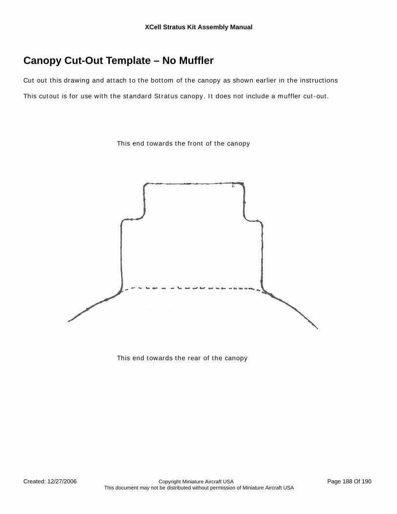
XCell Stratus Kit Assembly Manual
Created: 12/27/2006 Copyright Miniature Aircraft USA Page 188 Of 190 This document may not be distributed without permission of Miniature Aircraft USA
Canopy Cut-Out Template – No Muffler Cut out this drawing and attach to the bottom of the canopy as shown earlier in the instructions This cutout is for use with the standard Stratus canopy. It does not include a muffler cut-out. This end towards the front of the canopy
This end towards the rear of the canopy

XCell Stratus Kit Assembly Manual
Created: 12/27/2006 Copyright Miniature Aircraft USA Page 189 Of 190 This document may not be distributed without permission of Miniature Aircraft USA
Canopy Cut-Out Template – With Hatori SB16/SB17 Cut out the drawing on the next page and attach to the bottom of the canopy as shown earlier in the instructions. This cutout is for use with the standard Stratus canopy. It includes a cut-out for the Hatori SB16/SB17 muffler.
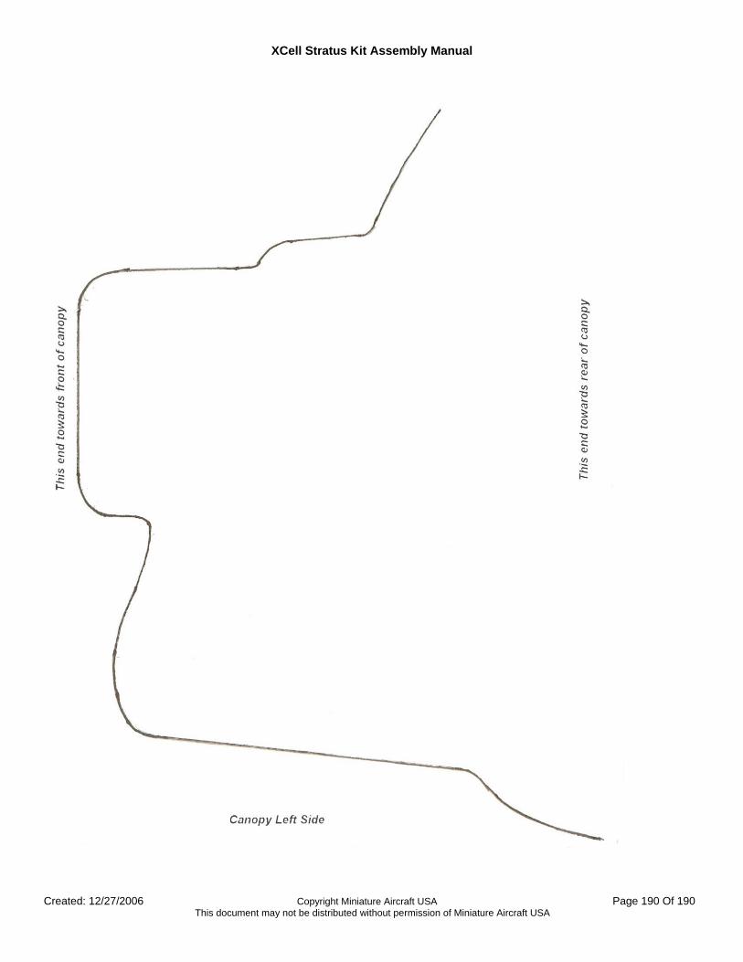
XCell Stratus Kit Assembly Manual
Created: 12/27/2006 Copyright Miniature Aircraft USA Page 190 Of 190 This document may not be distributed without permission of Miniature Aircraft USA