Embed Size (px)
Citation preview

1
Contents:Introduction............................................................................2Configurable Features.........................................................2-3Standard Features................................................................3-5Dip Switch Features................................................................6Unpacking & Pre-installation..................................................7Installation & Mounting............................................................7Amplifier Power Distribution.................................................8Troubleshooting..................................................................9 Siren Wiring Diagram.............................................................10Siren Specifications..............................................................11Lighting Specifications........................................................11Siren Control Head - Exploded View.......................................12Siren Control Head - Parts List................................................13Notes................................................................................14-15Warranty................................................................................16
SIREN PATENTED. See https://secure.code3pse.com/patents/
WARNINGSirens produce loud sounds that may damage hearing• Wear hearing protection when testing• Use siren only for emergency response• Roll up windows when siren is operating• Avoid exposure to the siren sound outside of vehicle
Read all instruction and warnings before installing and using.INSTALLER: This manual must be delivered to the end user of this equipment.
XCEL SERIES
IMPORTANT:
TM

2
!Sirens are an integral part of an effective audio/visual emergency warning system. However, sirens are only short range secondary warning devices. The use of a siren does not insure that all drivers can or will observe or react to an emergency warning signal, particularly at long distances or when either vehicle is traveling at a high rate of speed. Sirens should only be used in a combination with effective warning lights and never relied upon as a sole warning signal. Never take the right of way for granted. It is your responsibility to be sure you can proceed safely before entering an intersection driving against traffic, or responding at a high rate of speed.The effectiveness of this warning device is highly dependent upon correct mounting and wiring. Read and follow themanufacturer’s instructions before installing this device. The vehicle operator should check the equipment daily to insure that all features of the device operate correctly. To be effective, sirens must produce high sound levels that potentially can inflict hearing damage. Installers should be warned to wear hearing protection, clear bystanders from the area and not to operate the siren indoors during testing. Vehicle operators and occupants should assess their exposure to siren noise and determine what steps, such as consultation with professionals or use of hearing protection should be implemented to protect their hearing.This equipment is intended for use by authorized personnel only. It is the user’s responsibility to understand and obey all laws regarding emergency warning devices. The user should check all applicable city, state and federal laws and regulations. Code 3, Inc., assumes no liability for any loss resulting from the use of this warning device.Proper installation is vital to the performance of the siren and the safe operation of the emergency vehicle. It is important to recognize that the operator of the emergency vehicle is under psychological and physiological stress caused by the emergency situation. The siren system should be installed in such a manner as to: A) Not reduce the acoustical performance of the system, B) Limit as much as practical the noise level in the passenger compartment of the vehicle, C) Place the controls within convenient reach of the operator so that he can operate the system without losing eye contact with the roadway. Emergency warning devices often require high electrical voltages and/or currents. Properly protect and use caution around live electrical connections. Grounding or shorting of electrical connections can cause high current arcing, which can cause personal injury and/or severe vehicle damage, including fire. PROPER INSTALLATION COMBINED WITH OPERATOR TRAINING IN THE PROPER USE OF EMERGENCY WARNING DEVICES IS ESSENTIAL TO INSURE THE SAFETY OF EMERGENCY PERSONNEL AND THE PUBLIC.
WARNING
Standard FeaturesThe XCEL Siren consists of integrated controls and amplifier in a single package with 9 circuit lighting controls available as well. This model includes the following standard features:
- Primary Tones: WAIL, YELP, ALT TONE (Default Tone for ALT TONE is Hi-Lo but can be configured to Hyper-Yelp).- MANUAL Push-Button- AIR HORN Push-Button- 6 Auxiliary Controls: Default to be Toggle On/Off, can be individually configured to be Momentary Aux A - Aux E, Timed (8Sec) Aux F, and Latched
to individual levels of the 3 Level Switch.- PA and Radio RebroadcastConfigurable Features (Programming Mode-Front Face of Siren, L6 Models ONLY)Programming mode will allow you to configure: Backlighting, Latching of auxiliary switches to the 3 level switch, Auxiliary switch type (ON/OFF, Momentary, or 8 second timed), Park Kill (+ or -), Horn Ring In (+ or -), Light Alert, and Button Press feedback.
IntroductionThe XCEL Siren has been designed to meet the needs of all emergency vehicles. It incorporates many of the popular features of the past and uses microprocessor based circuitry. All standard features are available along with many new features: Fully Configurable 3-Level Switch, Selectable Tones, Adjustable Backlighting, Hands Free and much more.
!IMPORTANT WARNINGS TO USERS OF SIRENS: “Wail” and “Yelp” tones are in some cases (such as the state of California) the only recognized siren tones for calling for the right of way. Ancillary tones such as “Air Horn”, “Hi-Lo”, “Hyper-Yelp”, and “Hyper-Lo” in some cases do not provide as high a sound pressure level. It is recommended that these tones be used in a secondary mode to alert motorists to the presence of multiple emergency vehicles or to the momentary shift from the primary tone as an indication of the imminent presence of any emergency vehicle.WARNING

3
you will need to start again at step 4. Latching Auxiliary Buttons to 3 Level Switch - By moving the 3 level switch to any level, you can then press any of the auxilary buttons to add to that Level of the 3 Level Switch. Example, Moving the 3 Level Switch to Level 1, then pressing the Auxiliary Button A (A will illuminate RED) will add Aux A output to Level 1. After selections are made in any level, move the 3 Level Switch to next desired location and repeat process. When all levels are programmed to the desired settings, move the 3 Level Switch back to Level 0 and press the Manual Button to move to the next step.
Auxiliary Button Type (ON/OFF, Momentary, Timed) - By pressing any of the Auxiliary Buttons, the backlighting should either be solid ON RED or Flashing RED. If the button is solid ON RED, that means the button is in the ON/OFF setting, if the button is Flashing RED, that means this button is momentary (or timed 8 Seconds for Auxilary Button F). Once all Auxiliary Buttons are programmed to the desired setting, press the Manual Button to move to the next step.
Park Kill, Horn Ring In, Light Alert, Button Press Buzzer - Auxiliary Button A programs the Park Kill feature, if the button is solid ON RED, the Park Kill is a +12V signal, if the button is flashing RED, the Park Kill input will be a Ground signal. Auxiliary Button B programs the Horn Ring In feature, if the button is solid ON RED, the Horn Ring In is a +12V signal, if the button is flashing RED, the Horn Ring In is a Ground signal. Auxiliary C programs the Light Alert feature, if the button is solid ON RED, the internal buzzer will beep every 8 seconds if any lighting switch is ON, if the but-ton is flashing RED, Light Alert is disabled. Auxiliary Button D programs the Button Press Buzzer, if the button is solid ON RED, anytime a button is pressed, the buzzer will beep, if the button is flashing RED, this feature will be disabled. Once all the features have been programmed to the desired setting, press the Manual button to exit programming.
To change the backlighting intensity, Please follow the following instructions:1. Move Level Switch to Level 0 (furthest to the left)2. Turn all Auxiliary Switches off3. Move Rotary Knob to RAD (Radio)4. Press and hold MAN (Manual) button for at least 2 seconds (at this point the Auxiliary Button backlighting indication will turn RED) , then
release.5. Immediately press, in order, Auxiliary Buttons F - D - C - A6. If entered correctly, the Air Horn button will be flashing and you can now adust the backlighting intensity.
Adjustable Backlighting - The Backlighting can be adjusted as desired. Pressing the Air Horn button will change the backlighting brightness. There are 4 steps; Off, 30%, 70% 100% brightness. When finished making adjustments, press the Manual Button.
Standard Features3-Level Switch - This switch is used for changing the emergency warning mode. When the 3-Level Switch is switched to the far left position, the unit is off. When the 3-Level Switch is in the first position from the left, the level 1 configuration of the lights is turned on. When the 3-Level Switch is in the second position from the left, the level 1 & 2 configuration of lights are turned on. When the 3-Level Switch is in the third position from the left, the level 1, 2, & 3 configuration of the lights are turned on. Level 1, 2, & 3 activate the LightAlert. These default settings can be altered using the rear facing dip switches as well as entering programming mode.
WAIL Rotary Knob- This position produces the Wail tone when selected. Operation of this feature is affected by SirenLock, 3-Level Switch, Park Kill, and Title 13 features. See these sections for details.
YELP Rotary Knob - This position produces the Yelp tone when pressed. Operation of this feature is affected by SirenLock, 3-Level Switch, Park Kill, and Title 13 features. See these sections for details.
Figure 1
To enter into Programming Mode, follow the followinginstructions:1. Move Level Switch to Level 0 (furthest to the left)2. Turn all Auxiliary Switches off3. Move Rotary Knob to RAD (Radio)4. Press and hold MAN (Manual) button for at least 2
seconds (at this point the Auxiliary Button backlighting indication will turn RED) , then release.
5. Immediately press, in order, Auxiliary Buttons A - B - C - F
6. If entered correctly, the Air Horn button will be flashing and you are now in Programming mode, if you entered this incorrectly, the siren will automatically return and

4
Standard Features- Cont:ALT TONE Rotary Knob - This position produces either Hi-Lo or Hyper-Yelp dependent on Dip Switch 12. Operation of thisfeature is affected by SirenLock, 3-Level Switch, Park Kill, and Title 13 features. See these sections for details.
Radio (RRB) - This position operates Radio ReBroadcast over siren speakers. These inputs are transformer coupled to prevent loading of the radio. The audio from the radio is rebroadcast over the siren speakers. The siren tones do not operate when this is activated. All other control functions operate normally. To connect in the signal to be broadcast, simply connect the two signal lines to the RRB and RRB inputs of the Amplifier (polarity is not an issue). The RRB feature will automatically shutoff to protect from overheating of the XCEL Siren.
MANUAL Push-Button - In its default configuration, this push-button generates the Manual Wail tone. When pressed, the Manual Wail tone will ramp up to the maximum tone and hold. It will hold as long as the MANUAL push-button is held. When the MANUAL push-button is released, the tone will ramp down and return to the previous function. This button can work the Hit-N-Go mode as well. Operation of this feature is affected by SirenLock, 3-Level Switch, Park Kill, and Title 13 features. See these sections for details.
AIR HORN Push-Button - In its default configuration, the AIR HORN push-button produces the Air Horn tone as long as it is pressed. It willoverride all other siren tones. The AIR HORN push-button will work with Park Kill and SirenLock. Operation of this feature is affected by Title 13 features.
Auxiliary A-F Push-Buttons -As configured through the programming mode, six on/off Auxiliary push-buttons are readily accessible for controlling the Auxiliary outputs of the Amplifier. Each Auxiliary push-button can be custom labeled with the supplied label kit. Each push-button is backlighted when activated to alert the operator. The default setting is for each Auxiliary push-button to control the corresponding Auxiliary output of the Amplifier. Auxiliary A through F supplies power to the load through the connector pins labeled A thru F.
Hands-Free - The Hands-Free mode is directly linked to Auxiliary push-button E. By default, the Hands-Free mode is disabled. When Dip Switch 3 is Up (ON), the Auxiliary Push-Button E is then configured for Hands-Free. If Auxiliary Push-Button E is active, then Hands-Free mode is active, but waiting for an initial press of the horn ring to activate the WAIL. A second press of the horn ring will activate the YELP. Pressing the horn ring a third time will activate the ALT TONE. A fourth press of the horn ring will return to the WAIL. This type of scrolling will continue until the user deactivates the Hands-Free Scroll. Pressing the Auxiliary E turns off the tone and deactivates the Hands-Free Scroll. Pressing and holding the horn ring will turn off the tone, but leave Hands-Free in the active mode.
Hands-Free Level 3 Lighting - The Hands-Free mode has the option of working directly with Level 3 lighting. If Dip Switch 2 is Up (ON), the above Hands Free feature will also turn on Level 3 lighting. To activate and de-activate this feature, follow the above instructions under Hands-Free.
Horn Ring - The XCEL Siren accepts either a positive or a ground signal into the Horn Ring input, this is defined in Programming Mode. The Horn Ring signal is disconnected from the vehicle and connected to the Horn Ring input. The Horn Relay wire is then run from the Amplifier to the horn of the vehicle. This allows the Horn Ring to execute some of the user selectable functions of the XCEL Siren. The Horn Ring can be configured to multiple functions in the Siren Active and Siren Inactive modes of operation. The Horn Ring is set to Scroll in the Hands-Free mode and cannot be changed.
Horn Ring Transfer - The Horn Ring Transfer allows the Horn Ring to be disabled from the vehicle horn and the controls transferred to control other siren tones. The Horn Ring Transfer can be set to occur at Level 2 or Level 3.
Hit-N-Go - Hit-N-Go only works when a siren tone is active and if Dip Switch 7 is Up (ON). Once a siren tone is active, Hit-N-Go is activated simply by pressing the vehicle horn ring. It will go to the Override tone for 8 seconds and then return to the primary tone. The actual tone for the Hit-N-Go depends on which position the rotary knob is in. If the WAIL is active then the Hit-N-Go (Override) tone is the Yelp tone. If the YELP is active then the Hit-N-Go tone is the Hyper-Yelp 1 tone and if the ALT TONE push-button is active then the Hit-N-Go tone is the Hyper-Lo 1 tone. The MANUAL push-button is also a Hit-N-Go activator.
Scroll - Scroll only works when a siren tone is active and Dip Switch 7 is down (OFF). Once a siren tone is active, Scroll is activated simply by press-ing the vehicle horn ring. The XCEL Siren will Scroll from Wail to Yelp to Alt and then back to Wail, if Dip Switch 6 is up (ON), the XCEL Siren will Scroll from Waill to Yelp to Alt to OFF and then back to Wail. Holding the vehicle horn ring for greater than a half second will cause the XCEL Siren to generate the Air Horn.
Park Kill - By default, the Park Kill puts the siren tones in standby and drops out the Level 3B output. Park Kill occurs when the vehicle is shifted into park. The default for the polarity of the Park Kill input is +12V (Programmable to a GND). Once Park Kill is activated, the siren tones are in standby. The siren tones will remain in standby until the vehicle is shifted into drive and an action occurs such as pressing one of the Siren push-buttons, changing the position of the 3-Level Switch, or keying the microphone. The Level 3B and siren tones are in standby during Park Kill and the Auxiliary push-buttons are not affected by the Park Kill function.

5
Standard Features- Cont:SirenLock - SirenLock is used to allow the XCEL Siren to only generate the tones when in Level 3. When SirenLock is enabled, the XCEL Siren is ‘Locked’ from generating Primary tones until the 3-Level Switch is moved to Level 3. SirenLock does not affect the MANUAL and AIR HORN push-buttons. The default for SirenLock is disabled and the XCEL Siren will generate Primary tones when the rotary knob (Wail, Yelp or Alt) is activated regardless of the position of the 3-Level Switch. Siren Lock is selected via dip switch 4.
LightAlert - LightAlert feature will produce an audible “beep” on a periodic basis if any lighting is activated including Auxiliary push-buttons. This is intended to alert the operator that lights are on. By default, this is Enabled, if the user wishes to Disable it, this can be done via entering Program-ming Mode.
Speaker and Lighting Self Test - The XCEL siren is continuously running a Speaker and Lighting test making sure that there are no speaker is-sues (open or short) and checking to see if there are any Open fuses. The XCEL siren faceplate has two green LEDs below the rotary knob, LT and SP. These are lit at all times unless there is an issue. If there is an issue, the LED will remain off until the siren has seen the issue fixed. Example: Pressing an Aux push-button that has a blown fuse will turn off the LT LED, once the fuse has been replaced, pressing the Aux push-button again will allow the siren to check the fuse and turn back on the LT LED. SP light works in a similary way, if the XCEL siren detects a bad speaker during tone generation (Primary or Secondary tones), the SP LED will turn off and the siren will try every few seconds to generate tones until it sees a good speaker again. Once the XCEL siren detects a good speaker, the SP LED will turn back on.
Instant On - There is no “ON/OFF” switch. If the XCEL Siren is properly installed and the vehicle’s ignition is switched on, selecting any siren func-tion or keying the microphone will activate the selected siren function. If the Ignition is off, the user can still power up the auxiliary switches A - E (Switch F is on its own power source for Gun Locks) and the 3 Level Switch. All siren tones are deactivated until the XCEL siren detects the ignition is on.
Microphone - Push-To-Talk (PTT) is highest priority and overrides all other siren tones. Pressing the push-button on the microphone willautomatically override all siren tones and switch to the public address mode. The microphone is easily plugged into the Control Head with a modular phone plug. This allows the microphone to be unplugged for easy service or replacement.
Stuck Mic - If the PTT is pressed for 30 seconds , the XCEL Siren will disable the PTT and return to the previous operation. This will avoid the situa-tion where the PTT is “stuck” in the on position for extended periods. To continue using the PTT, release the PTT and press it again.
Blown Fuse Indicator - The XCEL Siren will give a visual warning via LEDS above the output connectors if there is no power being supplied to any 3-Level output or to the Auxiliary A through F outputs when they are turned ON. By default, anytime an output is turned on, the LED above the ouput at the rear of the siren will turn on as well, if the siren detects a blown fuse, not only will the LT light turn off on the front of the XCEL siren, the output indicator LED at the rear will turn off as well easily identifying which fuse blew. The fuses can be easily accessed through the top of the XCEL Siren.

6
Confi
gura
ble F
eatu
res f
or L
6 Mod
elsDi
p Sw
itch
UPDi
p Sw
itch
DOW
NDi
p Swi
tch 1
Califo
rnia
Title
13 O
NCa
liforn
ia Tit
le 13
OFF
Dip S
witch
2Ha
nds F
ree w
/ Lev
el 3 L
ightin
g ON
Hand
s Fre
e w/ L
evel
3 Ligh
ting O
FFDi
p Swi
tch 3
Hand
s Fre
e ON
Hand
s Fre
e OFF
Dip S
witch
4Si
ren L
ock O
NSi
ren L
ock O
FFDi
p Swi
tch 5
Horn
Ring
Tran
sfer A
lway
s Ena
bled
Horn
Ring
Tran
sfer o
n Dip
8 Sett
ing O
nlyDi
p Swi
tch 6
Scro
ll has
“OFF
” step
Scro
ll doe
s not
have
“OFF
’ step
Dip S
witch
7Hi
t-N-G
o Sc
roll
Dip S
witch
8Ho
rn R
ing Tr
ansfe
r Lev
el 3 O
nlyHo
rn R
ing Tr
ansfe
r in Le
vel 2
& 3
Dip S
witch
9No
Fun
ction
No F
uncti
onDi
p Swi
tch 12
Alt. T
one s
et as
Hyp
er-Y
elpAl
t. Ton
e set
as H
i-Lo
Dip 1
0 + D
ip 11
Dip 1
0 UP,
Dip 1
1 UP,
3 Lev
el Sw
itch i
s Pro
gres
sive
Dip 1
0 DOW
N, D
ip 11
DOW
N, 3
Leve
l Swi
tch is
Pro
gres
sive
Dip 1
0 + D
ip 11
Dip 1
0 UP,
Dip 1
1 DOW
N, 3
Leve
l Swi
tch is
Sem
i-Pro
gres
sive
Dip 1
0 DOW
N, D
ip 11
UP,
3 Lev
el Sw
itch i
s Ind
epen
dent
Confi
gura
ble F
eatu
res f
or N
on-L
ight
Co
ntro
l Mod
elsDi
p Sw
itch
UPDi
p Sw
itch
DOW
NDi
p 1 +
Dip
2Di
p 1 U
P, Di
p 2 U
P, Ba
cklig
hting
Brig
htnes
s Lev
el 0
Dip 1
DOW
N, D
ip 2 D
OWN,
Bac
kligh
ting B
rightn
ess L
evel
3Di
p 1 +
Dip
2Di
p 1 U
P, Di
p 2 D
own,
Back
lighti
ng B
rightn
ess L
evel
2Di
p 1 D
own,
Dip 2
UP,
Back
lighti
ng B
rightn
ess L
evel
1Di
p Swi
tch 3
Park
Kill I
nput
+12V
Park
Kill I
nput
Grou
ndDi
p Swi
tch 4
Horn
Ring
Inpu
t +12
VHo
rn R
ing In
put G
roun
dDi
p Swi
tch 5
Butto
n Pre
ss B
eep O
NBu
tton P
ress
Bee
p OFF
Dip S
witch
6Sc
roll h
as “O
FF” s
tepSc
roll d
oes n
ot ha
ve “O
FF” s
tepDi
p Swi
tch 7
Hit-N
-Go
Scro
llDi
p Swi
tch 8
No F
uncti
onNo
Fun
ction
Dip S
witch
9No
Fun
ction
No F
uncti
onDi
p Swi
tch 10
No F
uncti
onNo
Fun
ction
Dip S
witch
11No
Fun
ction
No F
uncti
onDi
p Swi
tch 12
Alt. T
one s
et as
Hyp
er-Y
elpAl
t. Ton
e set
as H
i-Lo

7
Unpacking & Pre-installationAfter unpacking your XCEL Siren, carefully inspect the unit and associated parts for any damage that may have been caused in transit. Report any dam-age to the carrier immediately.
Verify all components have been delivered. The box should contain the XCEL Siren, microphone, hard-ware bag, legend set and user manuals bag.
Installation & MountingThe XCEL Siren is designed mount directly into the console of most leadingmanufacturers (see Figure 3).It may also be mounted above the dash, below the
!All devices should be mounted in accordance with the manufacturer’s instructions and securely fastened to vehicle elements of sufficient strength to withstand the forces applied to the device. Ease of operation and convenience to the operator should be the prime consideration when mounting the siren and controls. Adjust the mounting angle to allow maximum operator vis-ibility. Do not mount the Control Head Module in a location that will obstruct the drivers view. Mount the microphone clip in a convenient location to allow the operator easy access. Devices should be mounted only in locations that conform to their SAE identification code as described in SAE Standard J1849. For example, electronics designed for interior mounting should not be placed underhood, etc. Controls should be placed within convenient reach* of the driver or if intended for two person operation the driver and/or passenger. In some vehicles, multiple control switches and/or using methods such as “horn ring transfer” which utilizes the vehicle horn switch to toggle between siren tones may be necessary for convenient operation from two positions.
*Convenient reach is defined as the ability of the operator of the siren system to manipulate the controls from their normal driv-ing/riding position without excessive movement away from the seat back or loss of eye contact with the roadway.
WARNING
dash or on thetransmission tunnel using the mounting hardware supplied (see Figure 2). Also reference page 12 and 13 for description of components and Code 3 part numbers. Ease of operation and convenience to the operator should be the prime consideration when mounting the siren and controls. Whenchoosing a mounting location the user must consider the deployment area for the air bag of the vehicle and other factors which might impact the safety of the vehicle occupants.
NOTE: Setups and adjustments will be made in steps that may requireaccess to the rear area of the unit. Plan the installation and wiringaccordingly.
Console Manufacturer Panel Mount Part Number(S)Havis Shields C-EB35-XCL-1PGamber Johnson 1-Piece = 7160-0569, 2-Piece = 7140-0838Jotto Desk 425-6442Lund LI-OPB-325-XCEL Troy FP-C3-XCEL
Figure 2
Figure 3

8
WARNING ! Connection of a 58 watt speaker to the siren amplifier will cause the speaker to burn out, and will void the speaker warranty!
WARNING ! Any electronic device may create or be affected by electromagnetic interference. After installation of any electronic device, operate all equipment simultaneously to insure that operation is free of interference.
WARNING !Utilizing non-factory specified screws and/or mounting brackets and/or the improper number of screws may result in failure of the mounting system and severe damage to the vehicle as well as loss of warranty coverage on the equipment.
Amplifier Power DistributionThe Level 1, 2, 3A and 3B outputs can supply a maximum of 15 Amps each or a combined total of 50 Amps. Each Level has a 20 Amp fuse installed inside the Amplifier. Fuses may be accessed through the panel on top of the Amplifier.
The Auxiliary outputs A, B, C, D, E, and F can supply a maximum of 10 amps each or a combined total of 60A. Auxiliary outputs A, B, C, D, E, and F have 15 amp fuses. Fuses may be accessed through the panel on top of the Amplifier.
9
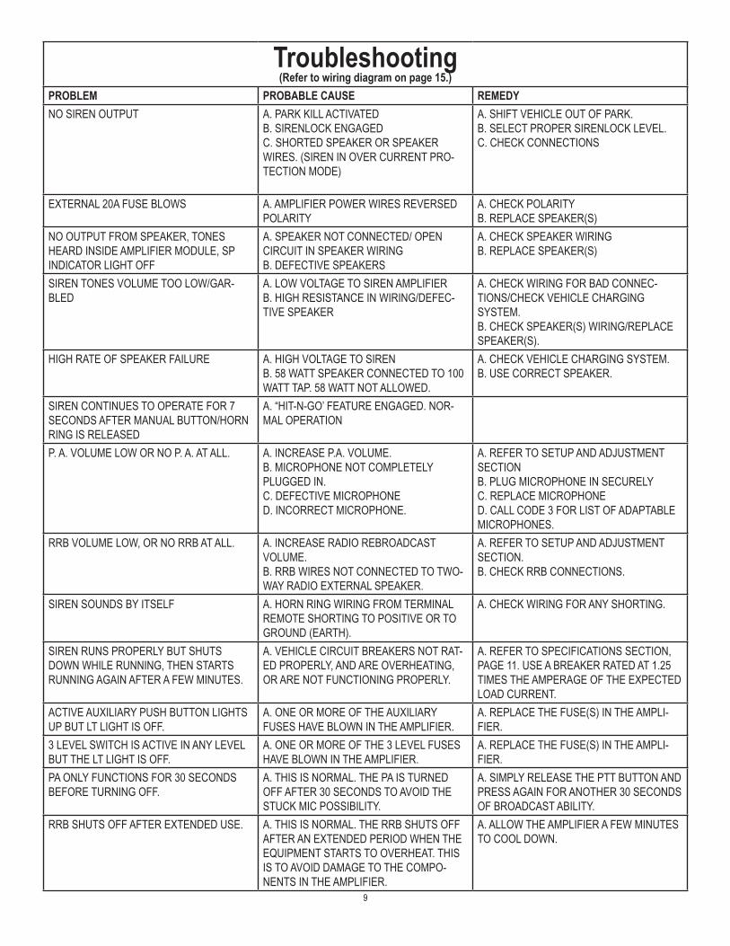
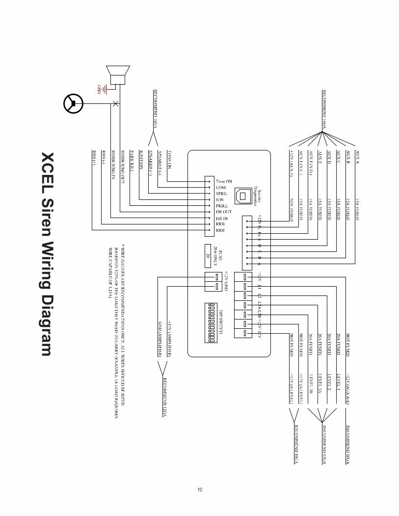
Troubleshooting(Refer to wiring diagram on page 15.)
PROBLEM PROBABLE CAUSE REMEDYNO SIREN OUTPUT A. PARK KILL ACTIVATED
B. SIRENLOCK ENGAGEDC. SHORTED SPEAKER OR SPEAKER WIRES. (SIREN IN OVER CURRENT PRO-TECTION MODE)
A. SHIFT VEHICLE OUT OF PARK.B. SELECT PROPER SIRENLOCK LEVEL.C. CHECK CONNECTIONS
EXTERNAL 20A FUSE BLOWS A. AMPLIFIER POWER WIRES REVERSED POLARITY
A. CHECK POLARITYB. REPLACE SPEAKER(S)
NO OUTPUT FROM SPEAKER, TONES HEARD INSIDE AMPLIFIER MODULE, SP INDICATOR LIGHT OFF
A. SPEAKER NOT CONNECTED/ OPEN CIRCUIT IN SPEAKER WIRINGB. DEFECTIVE SPEAKERS
A. CHECK SPEAKER WIRINGB. REPLACE SPEAKER(S)
SIREN TONES VOLUME TOO LOW/GAR-BLED
A. LOW VOLTAGE TO SIREN AMPLIFIERB. HIGH RESISTANCE IN WIRING/DEFEC-TIVE SPEAKER
A. CHECK WIRING FOR BAD CONNEC-TIONS/CHECK VEHICLE CHARGING SYSTEM.B. CHECK SPEAKER(S) WIRING/REPLACE SPEAKER(S).
HIGH RATE OF SPEAKER FAILURE A. HIGH VOLTAGE TO SIRENB. 58 WATT SPEAKER CONNECTED TO 100 WATT TAP. 58 WATT NOT ALLOWED.
A. CHECK VEHICLE CHARGING SYSTEM.B. USE CORRECT SPEAKER.
SIREN CONTINUES TO OPERATE FOR 7 SECONDS AFTER MANUAL BUTTON/HORN RING IS RELEASED
A. “HIT-N-GO’ FEATURE ENGAGED. NOR-MAL OPERATION
P. A. VOLUME LOW OR NO P. A. AT ALL. A. INCREASE P.A. VOLUME.B. MICROPHONE NOT COMPLETELY PLUGGED IN.C. DEFECTIVE MICROPHONED. INCORRECT MICROPHONE.
A. REFER TO SETUP AND ADJUSTMENT SECTIONB. PLUG MICROPHONE IN SECURELYC. REPLACE MICROPHONED. CALL CODE 3 FOR LIST OF ADAPTABLE MICROPHONES.
RRB VOLUME LOW, OR NO RRB AT ALL. A. INCREASE RADIO REBROADCAST VOLUME.B. RRB WIRES NOT CONNECTED TO TWO-WAY RADIO EXTERNAL SPEAKER.
A. REFER TO SETUP AND ADJUSTMENT SECTION.B. CHECK RRB CONNECTIONS.
SIREN SOUNDS BY ITSELF A. HORN RING WIRING FROM TERMINAL REMOTE SHORTING TO POSITIVE OR TO GROUND (EARTH).
A. CHECK WIRING FOR ANY SHORTING.
SIREN RUNS PROPERLY BUT SHUTS DOWN WHILE RUNNING, THEN STARTS RUNNING AGAIN AFTER A FEW MINUTES.
A. VEHICLE CIRCUIT BREAKERS NOT RAT-ED PROPERLY, AND ARE OVERHEATING, OR ARE NOT FUNCTIONING PROPERLY.
A. REFER TO SPECIFICATIONS SECTION, PAGE 11. USE A BREAKER RATED AT 1.25 TIMES THE AMPERAGE OF THE EXPECTED LOAD CURRENT.
ACTIVE AUXILIARY PUSH BUTTON LIGHTS UP BUT LT LIGHT IS OFF.
A. ONE OR MORE OF THE AUXILIARY FUSES HAVE BLOWN IN THE AMPLIFIER.
A. REPLACE THE FUSE(S) IN THE AMPLI-FIER.
3 LEVEL SWITCH IS ACTIVE IN ANY LEVEL BUT THE LT LIGHT IS OFF.
A. ONE OR MORE OF THE 3 LEVEL FUSES HAVE BLOWN IN THE AMPLIFIER.
A. REPLACE THE FUSE(S) IN THE AMPLI-FIER.
PA ONLY FUNCTIONS FOR 30 SECONDS BEFORE TURNING OFF.
A. THIS IS NORMAL. THE PA IS TURNED OFF AFTER 30 SECONDS TO AVOID THE STUCK MIC POSSIBILITY.
A. SIMPLY RELEASE THE PTT BUTTON AND PRESS AGAIN FOR ANOTHER 30 SECONDS OF BROADCAST ABILITY.
RRB SHUTS OFF AFTER EXTENDED USE. A. THIS IS NORMAL. THE RRB SHUTS OFF AFTER AN EXTENDED PERIOD WHEN THE EQUIPMENT STARTS TO OVERHEAT. THIS IS TO AVOID DAMAGE TO THE COMPO-NENTS IN THE AMPLIFIER.
A. ALLOW THE AMPLIFIER A FEW MINUTES TO COOL DOWN.
10
XCEL Siren W
iring Diagram

11
Siren SpecificationsSiren Section:
Input Voltage 10 to 16 VDC and ground - 12V units (Note: Operation of 12V units above 15 VDC for an extended period of time may result in speaker damage.)
Operating Current 100W: 8 Amps @ 13.6V with 11-ohm load (100 Watt Speaker) - 12V units 200W: 14 Amps @ 13.6V with 5.5-ohm load (2-100 Watt Speakers) - 12V units
(NOTE: There is no 58 Watt speaker connection available.)
Standby Current Ignition On < 200mA Ignition Off < 3mA
Cycle Rate Wail - 11 cycles/minute Yelp - 200 cycles/minute
Voltage Output ~ 66 Vpp
Lighting SpecificationsWarning Light Control: 3-Level Switch, 4 Outputs, 50 Amps maximum combined total
Level 1 & 2: 15 Amp Maximum Each Level Green (1) & Yellow (2) LED Indication
Level 3A & 3B: 15 Amp Maximum Each Level Red (3) LED Indication
AUX A thru F: 10 Amp Maximum Each Aux 60 Amp Maximum Total
System - Weight: Siren 4.5 lbs (1.9 Kg)
Boxed Unit 6.0 lbs (4.3 Kg)
Size: Amplifier 5.585”L x 6.520”W x 2.765”H
Temperature: -22F thru +149F (-30C thru +65C) SAE Equipment Type EVS1

12
WARRANTY Code 3®, Inc.’s emergency devices are tested and found to be operational at the time of manufacture. Provided they are installed and operated in accordance with manufacturer’s recommendations, Code 3®, Inc. guarantees all parts and components except the lamps to a period of 1 year, LED Lighthead modules to a period of 5 years (unless otherwise expressed) from the date of purchase or delivery, whichever is later. Units demonstrated to be defective within the warranty period will be repaired or replaced at the factory service center at no cost.
Use of lamp or other electrical load of a wattage higher than installed or recommended by the factory, or use of inappropriate or inadequate wiring or circuit protection causes this warranty to become void. Failure or destruction of the product resulting from abuse or unusual use and/or accidents is not covered by this warranty. Code 3®, Inc. shall in no way be liable for other damages including consequential, indirect or special damages whether loss is due to negligence or breach of warranty.
CODE 3®, INC. MAKES NO OTHER EXPRESS OR IMPLIED WARRANTY INCLUDING, WITHOUT LIMITATION, WARRANTIES OF FITNESS OR MERCHANTABILITY, WITH RESPECT TO THIS PRODUCT.
PRODUCT RETURNSIf a product must be returned for repair or replacement*, please contact our factory to obtain a Return Goods Authorization Number (RGA number) before you ship the product to Code 3®, Inc. Write the RGA number clearly on the package near the mailing label. Be sure you use sufficient packing materials to avoid damage to the product being returned while in transit.
*Code 3®, Inc. reserves the right to repair or replace at its discretion. Code 3®, Inc. assumes no responsibility or liability for expenses incurred for the removal and /or reinstallation of products requiring service and/or repair; nor for the packaging, handling, and shipping: nor for the handling of products returned to sender after the service has been rendered.
Problems or Questions? Call The Technical Assistance HOTLINE - (314) 996-2800
Code 3, Inc.10986 N. Warson Road
St. Louis, Missouri 63114-2029—USAPh. (314) 426-2700 Fax (314) 426-1337
www.code3pse.com
Code 3,® Inc., a subsidiary ofECCO Safety Group
Revision 1, 07/14 - Instruction Book Part No. T55868©2014 ECCO Safety Group. Printed in USACode 3 is a registered trademark of
Code 3, Inc.