Embed Size (px)
Citation preview
XAP™ 400 Audio Conferencing System
Installation & Operation Manual
ii
Technical Services Group ~ 1-800-283-5936 (USA) ~ 1-801-974-3760
© 2002 ClearOne Communications, Inc. All
rights reserved. No part of this document
may be reproduced in any form or by any
means without written permission from
ClearOne Communications. Printed in the
United States of America. ClearOne
Communications reserves specific privileges.
Information in this document is subject to
change without notice.
XAP 400 Installation andOperation ManualClearOne Part No. 800-151-201 July 2002 (Rev. 2.1)
iii
Technical Services Group ~ 1-800-283-5936 (USA) ~ 1-801-974-3760
XAP 400 Installation and Operation Manual
Table of Contents
CHAPTER 1: Introduction . . . . . . . . . . . . . . . . . . . . . . . . . .1
Features . . . . . . . . . . . . . . . . . . . . . . . . . . . . . . . . . . . . . . . . . . . . . . . . . . . .1
Professional Services Group . . . . . . . . . . . . . . . . . . . . . . . . . . . . . . . . . . . . .2
Product registration . . . . . . . . . . . . . . . . . . . . . . . . . . . . . . . . . . . . .3
Product returns . . . . . . . . . . . . . . . . . . . . . . . . . . . . . . . . . . . . . . . . .3
Unpacking . . . . . . . . . . . . . . . . . . . . . . . . . . . . . . . . . . . . . . . . . . . . . . . . . .3
Controls and Connections . . . . . . . . . . . . . . . . . . . . . . . . . . . . . . . . . . . . . . .4
Front panel . . . . . . . . . . . . . . . . . . . . . . . . . . . . . . . . . . . . . . . . . . . .4
Rear panel . . . . . . . . . . . . . . . . . . . . . . . . . . . . . . . . . . . . . . . . . . . .5
Networking . . . . . . . . . . . . . . . . . . . . . . . . . . . . . . . . . . . . . . . . . . . . . . . . . .6
Expansion bus . . . . . . . . . . . . . . . . . . . . . . . . . . . . . . . . . . . . . . . . .6
Operational Requirements . . . . . . . . . . . . . . . . . . . . . . . . . . . . . . . . . . . . . . .7
Power . . . . . . . . . . . . . . . . . . . . . . . . . . . . . . . . . . . . . . . . . . . . . . .7
Telephone line . . . . . . . . . . . . . . . . . . . . . . . . . . . . . . . . . . . . . . . . .7
Equipment placement . . . . . . . . . . . . . . . . . . . . . . . . . . . . . . . . . . . .8
Environmental . . . . . . . . . . . . . . . . . . . . . . . . . . . . . . . . . . . . . . . . .8
CHAPTER 2: Installation . . . . . . . . . . . . . . . . . . . . . . . . . . .9
Hardware Setup . . . . . . . . . . . . . . . . . . . . . . . . . . . . . . . . . . . . . . . . . . . . . .9
To connect the unit . . . . . . . . . . . . . . . . . . . . . . . . . . . . . . . . . . . . . .10
Networking Units . . . . . . . . . . . . . . . . . . . . . . . . . . . . . . . . . . . . . . . . . . . . .11
Expansion bus connections . . . . . . . . . . . . . . . . . . . . . . . . . . . . . . . . .11
Device IDs . . . . . . . . . . . . . . . . . . . . . . . . . . . . . . . . . . . . . . . . . . . .12
Mixer mode . . . . . . . . . . . . . . . . . . . . . . . . . . . . . . . . . . . . . . . . . . .12
LCD Programming . . . . . . . . . . . . . . . . . . . . . . . . . . . . . . . . . . . . . . . . . . . .13
LCD menu tree . . . . . . . . . . . . . . . . . . . . . . . . . . . . . . . . . . . . . . . . .13
System menu . . . . . . . . . . . . . . . . . . . . . . . . . . . . . . . . . . . . . . . . . . .14
RS-232 menu . . . . . . . . . . . . . . . . . . . . . . . . . . . . . . . . . . . . . . . . . .15
Meter menu . . . . . . . . . . . . . . . . . . . . . . . . . . . . . . . . . . . . . . . . . . .16
Inputs menu . . . . . . . . . . . . . . . . . . . . . . . . . . . . . . . . . . . . . . . . . . .18
Outputs menu . . . . . . . . . . . . . . . . . . . . . . . . . . . . . . . . . . . . . . . . . .18
iv
Technical Services Group ~ 1-800-283-5936 (USA) ~ 1-801-974-3760
CHAPTER 3: System Configuration . . . . . . . . . . . . . . . . . . .21
G-Ware Requirements . . . . . . . . . . . . . . . . . . . . . . . . . . . . . . . . . . . . . . . . . .21
Creating floppy disk copies . . . . . . . . . . . . . . . . . . . . . . . . . . . . . . . .22
Installing G-Ware . . . . . . . . . . . . . . . . . . . . . . . . . . . . . . . . . . . . . . . . . . . . .22
Site Setup . . . . . . . . . . . . . . . . . . . . . . . . . . . . . . . . . . . . . . . . . . . . . . . . . . .23
Creating a new site . . . . . . . . . . . . . . . . . . . . . . . . . . . . . . . . . . . . . .23
Adding a XAP 400 . . . . . . . . . . . . . . . . . . . . . . . . . . . . . . . . . . . . . .24
Configuring Unit Properties . . . . . . . . . . . . . . . . . . . . . . . . . . . . . . . .25
G-Ware Screens . . . . . . . . . . . . . . . . . . . . . . . . . . . . . . . . . . . . . . . . . . . . . .27
Flow Screen . . . . . . . . . . . . . . . . . . . . . . . . . . . . . . . . . . . . . . . . . . .27
Matrix Screen . . . . . . . . . . . . . . . . . . . . . . . . . . . . . . . . . . . . . . . . . .27
Audio Routing . . . . . . . . . . . . . . . . . . . . . . . . . . . . . . . . . . . . . . . . . . . . . . . .30
Expansion bus O—Z routing . . . . . . . . . . . . . . . . . . . . . . . . . . . . . . . .30
Process A—D routing . . . . . . . . . . . . . . . . . . . . . . . . . . . . . . . . . . . . .30
Cross point attenuation . . . . . . . . . . . . . . . . . . . . . . . . . . . . . . . . . . .30
Matrix report . . . . . . . . . . . . . . . . . . . . . . . . . . . . . . . . . . . . . . . . . .31
Inputs and outputs . . . . . . . . . . . . . . . . . . . . . . . . . . . . . . . . . . . . . . . . . . . .32
Inputs 1—4 . . . . . . . . . . . . . . . . . . . . . . . . . . . . . . . . . . . . . . . . . . . .32
Inputs 5—8 . . . . . . . . . . . . . . . . . . . . . . . . . . . . . . . . . . . . . . . . . . . .44
Outputs 1—9 . . . . . . . . . . . . . . . . . . . . . . . . . . . . . . . . . . . . . . . . . . .46
Expansion Buses . . . . . . . . . . . . . . . . . . . . . . . . . . . . . . . . . . . . . . . . . . . . . .48
From Expansion Bus O—Z . . . . . . . . . . . . . . . . . . . . . . . . . . . . . . . . .48
To Expansion Bus O—Z . . . . . . . . . . . . . . . . . . . . . . . . . . . . . . . . . . .48
Processing . . . . . . . . . . . . . . . . . . . . . . . . . . . . . . . . . . . . . . . . . . . . . . . . . .49
Processing A—D . . . . . . . . . . . . . . . . . . . . . . . . . . . . . . . . . . . . . . . . .49
Telco Setup . . . . . . . . . . . . . . . . . . . . . . . . . . . . . . . . . . . . . . . . . . . . . . . . . .55
To configure telco settings . . . . . . . . . . . . . . . . . . . . . . . . . . . . . . . . .55
Telco Transmit and Receive . . . . . . . . . . . . . . . . . . . . . . . . . . . . . . . . . . . . . .57
Telco Transmit . . . . . . . . . . . . . . . . . . . . . . . . . . . . . . . . . . . . . . . . . .57
Telco Receive . . . . . . . . . . . . . . . . . . . . . . . . . . . . . . . . . . . . . . . . . . .58
CHAPTER 4: Advanced Configuration . . . . . . . . . . . . . . . . .59
Presets . . . . . . . . . . . . . . . . . . . . . . . . . . . . . . . . . . . . . . . . . . . . . . . . . . . . .59
Overview . . . . . . . . . . . . . . . . . . . . . . . . . . . . . . . . . . . . . . . . . . . . . .59
Creating Presets . . . . . . . . . . . . . . . . . . . . . . . . . . . . . . . . . . . . . . . .59
Running presets . . . . . . . . . . . . . . . . . . . . . . . . . . . . . . . . . . . . . . . . .64
v
Technical Services Group ~ 1-800-283-5936 (USA) ~ 1-801-974-3760
Running multiple presets simultaneously . . . . . . . . . . . . . . . . . . . . . .64
Macros . . . . . . . . . . . . . . . . . . . . . . . . . . . . . . . . . . . . . . . . . . . . . . . . . . . . .67
Creating macros . . . . . . . . . . . . . . . . . . . . . . . . . . . . . . . . . . . . . . . .67
Editing macros . . . . . . . . . . . . . . . . . . . . . . . . . . . . . . . . . . . . . . . . . .69
Running macros . . . . . . . . . . . . . . . . . . . . . . . . . . . . . . . . . . . . . . . . .70
CHAPTER 5: Operation . . . . . . . . . . . . . . . . . . . . . . . . . . . .71
Using the XAP 400 . . . . . . . . . . . . . . . . . . . . . . . . . . . . . . . . . . . . . . . . . . .71
To answer a call . . . . . . . . . . . . . . . . . . . . . . . . . . . . . . . . . . . . . . . .71
To make and disconnect a call . . . . . . . . . . . . . . . . . . . . . . . . . . . . .71
Using the Dial interface . . . . . . . . . . . . . . . . . . . . . . . . . . . . . . . . . . . . . . . .72
To make and disconnect a call . . . . . . . . . . . . . . . . . . . . . . . . . . . . . .72
To dial multiple numbers . . . . . . . . . . . . . . . . . . . . . . . . . . . . . . . . . .72
To mute . . . . . . . . . . . . . . . . . . . . . . . . . . . . . . . . . . . . . . . . . . . . . . .72
Touch-tone dialing . . . . . . . . . . . . . . . . . . . . . . . . . . . . . . . . . . . . . . .73
Utilities . . . . . . . . . . . . . . . . . . . . . . . . . . . . . . . . . . . . . . . . . . . . . . . . . . . .74
Signal Generator . . . . . . . . . . . . . . . . . . . . . . . . . . . . . . . . . . . . . . . .74
Document Compare Utility . . . . . . . . . . . . . . . . . . . . . . . . . . . . . . . .75
Print Reports . . . . . . . . . . . . . . . . . . . . . . . . . . . . . . . . . . . . . . . . . .78
Copy and paste settings . . . . . . . . . . . . . . . . . . . . . . . . . . . . . . . . . . .78
GFirm Firmware Upgrade . . . . . . . . . . . . . . . . . . . . . . . . . . . . . . . . .79
G-Ware Switcher . . . . . . . . . . . . . . . . . . . . . . . . . . . . . . . . . . . . . . . .81
Message Log . . . . . . . . . . . . . . . . . . . . . . . . . . . . . . . . . . . . . . . . . . .82
Monitoring views . . . . . . . . . . . . . . . . . . . . . . . . . . . . . . . . . . . . . . . . . . . . .83
Gate View . . . . . . . . . . . . . . . . . . . . . . . . . . . . . . . . . . . . . . . . . . . . .83
Meter Views . . . . . . . . . . . . . . . . . . . . . . . . . . . . . . . . . . . . . . . . . . .83
Telco meters . . . . . . . . . . . . . . . . . . . . . . . . . . . . . . . . . . . . . . . . . . .84
CHAPTER 6: Control . . . . . . . . . . . . . . . . . . . . . . . . . . . . .87
GPIO Builder . . . . . . . . . . . . . . . . . . . . . . . . . . . . . . . . . . . . . . . . . . . . . . . .87
Control/Status A . . . . . . . . . . . . . . . . . . . . . . . . . . . . . . . . . . . . . . . .87
Remote Builder . . . . . . . . . . . . . . . . . . . . . . . . . . . . . . . . . . . . . . . . . . . . . . .88
XAP IR Remote . . . . . . . . . . . . . . . . . . . . . . . . . . . . . . . . . . . . . . . .88
ClearOne Control Panels . . . . . . . . . . . . . . . . . . . . . . . . . . . . . . . . . .89
RS-232 Port . . . . . . . . . . . . . . . . . . . . . . . . . . . . . . . . . . . . . . . . . . . . . . . . .92
Remote modem access . . . . . . . . . . . . . . . . . . . . . . . . . . . . . . . . . . . .92
vi
Technical Services Group ~ 1-800-283-5936 (USA) ~ 1-801-974-3760
Serial commands . . . . . . . . . . . . . . . . . . . . . . . . . . . . . . . . . . . . . . . .92
Command strings . . . . . . . . . . . . . . . . . . . . . . . . . . . . . . . . . . . . . . . .93
APPENDICES . . . . . . . . . . . . . . . . . . . . . . . . . . . . . . . . . .95
Appendix A: Specifications . . . . . . . . . . . . . . . . . . . . . . . . . . . . . . . . . . . . . .95
Appendix B: Pinouts . . . . . . . . . . . . . . . . . . . . . . . . . . . . . . . . . . . . . . . . . . .97
Appendix C: Control Panel . . . . . . . . . . . . . . . . . . . . . . . . . . . . . . . . . . . . . .101
Appendix D: Accessories . . . . . . . . . . . . . . . . . . . . . . . . . . . . . . . . . . . . . . . .103
Appendix E: Serial Commands . . . . . . . . . . . . . . . . . . . . . . . . . . . . . . . . . . .104
Appendix F: Warranty . . . . . . . . . . . . . . . . . . . . . . . . . . . . . . . . . . . . . . . . .146
Appendix G: Compliance . . . . . . . . . . . . . . . . . . . . . . . . . . . . . . . . . . . . . . . .148
Glossary . . . . . . . . . . . . . . . . . . . . . . . . . . . . . . . . . . . . . . . . . . . . . . . . . . . .152
Index . . . . . . . . . . . . . . . . . . . . . . . . . . . . . . . . . . . . . . . . . . . . . . . . . . . . . .162
Technical Services Group ~ 1-800-283-5936 (USA) ~ 1-801-974-3760
CHAPTER 1: Introduction
Congratulations on purchasing the XAP™ 400 Audio Conferencing System. The
XAP 400 combines a highly advanced eight-by-eight digital matrix mixer that
features Gentner® Distributed Echo Cancellation®, noise cancellation, and audio
processing with a single-line digital telephone hybrid. This combination provides the
highest quality audio for a variety of audio and video conferencing applications–all
in a single one-rack unit.
• Gentner Distributed Echo Cancellation–four microphone/line echo
cancellers remove echo in even the most difficult environments.
• EC Reference summing enables the XAP 400 to reference various signals for
an echo cancellation reference without requiring a dedicated output.
• Noise cancellation reduces background noise such as that caused by fans or
air conditioning.
• Four independent processing blocks, each with 15 filters, delay, and
compressors, provide pinpoint audio configuration.
• Four mic/line inputs, four line inputs, and eight outputs.
• Enhanced expansion bus provides network capabilities. Eight XAP 400s or
XAP 800s can be networked for up to 64 microphone inputs.
• Fully configurable matrix which allows you to route any input to any output
or combination of outputs.
• Front panel control of mute and gain on inputs and outputs.
• Safety mute button on the toolbar that mutes all outputs if feedback occurs
during the configuration process.
• ClearOne’s 100% digital signal processing (DSP) technology ensures
crystal-clear audio with the deepest, most reliable hybrid null.
• International configuration of telephone hybrid setting
• Built-in telephone interface with:
~ Telco noise cancellation
~ Touch-tone dialing capability (40 character dial string)
~ Full-time telco echo cancellation with 31 millisecond tail time
CHAPTER 1: Introduction
Features
Introduction ~ Professional Services Group2
Technical Services Group ~ 1-800-283-5936 (USA) ~ 1-801-974-3760
Professional Services Group
If you need any additional information on how to install, set up, or operate your
system, please contact us at one of the locations listed below. We welcome and
encourage your comments so we can continue to improve our products and serve
your needs.
ClearOne Communications ~ 1825 Research Way ~ Salt Lake City, Utah 84119
Technical Support
Telephone: 1.800.283.5936(USA) or 1.801.974.3760
Fax: 1.801.977.0087
E-mail: [email protected]
Web site: www.clearone.com
Sales and Customer Service
Telephone: 1.800.945.7730 (USA) or 1.801.975.7200
Fax: 1.800.933.5107 (USA) or 1.801.977.0087
E-mail: [email protected]
ClearOne Communications EuMEA GmbH
Leonhardstr. 16-18, D-90443 Nuremberg, Germany
Telephone: +49 911 955159-0
Fax: +49 911 955159-10
E-mail: [email protected]
~ Selectable caller automatic level control (ALC)
~ Adjustable dial tone, DTMF attenuation
~ Continual adaptation to telephone line conditions
~ Digital anti-alias filter minimizes hum and Central Office switching noise
~ Analog telephone line compatibility
• 10W speaker amp output.
• Program and operate with a connected PC or any other type of serial remote
control device via expansion bus or RS-232 port.
3Introduction ~ Unpacking
Technical Services Group ~ 1-800-283-5936 (USA) ~ 1-801-974-3760
Product registration
Please register your XAP 400 online by visiting ClearOne Technical Support at
www.clearone.com. When your product is properly registered, ClearOne
Communications is better able to serve you should you require technical assistance.
Registration information is also used to notify you of upgrades and new product
information.
Product returns
All product returns require a return authorization (RA) number. Please contact
ClearOne Technical Support before attempting to return your XAP 400 unit.
ClearOne is not responsiblefor product damageincurred during shipment.
You must make claims directly withthe carrier. Inspect your shipmentcarefully for obvious signs ofdamage. If the shipment appears tobe damaged, retain the originalboxes and packing material forinspection by the carrier. Contactyour carrier immediately.
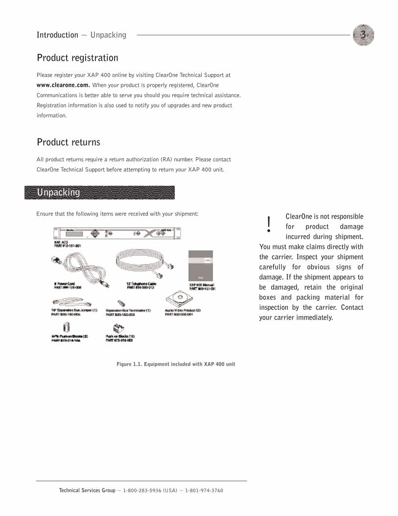
Unpacking
Ensure that the following items were received with your shipment:
!
Figure 1.1. Equipment included with XAP 400 unit
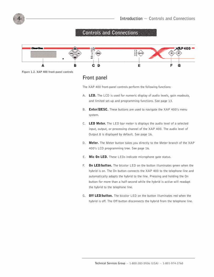
Figure 1.2. XAP 400 front-panel controls
Introduction ~ Controls and Connections4
Technical Services Group ~ 1-800-283-5936 (USA) ~ 1-801-974-3760
Controls and Connections
Front panel
The XAP 400 front-panel controls perform the following functions:
A. LCD. The LCD is used for numeric display of audio levels, gain readouts,
and limited set-up and programming functions. See page 13.
B. Enter/��/ESC. These buttons are used to navigate the XAP 400’s menu
system.
C. LED Meter. The LED bar meter is displays the audio level of a selected
input, output, or processing channel of the XAP 400. The audio level of
Output 8 is displayed by default. See page 16.
D. Meter. The Meter button takes you directly to the Meter branch of the XAP
400’s LCD programming tree. See page 16.
E. Mic On LED. These LEDs indicate microphone gate status.
F. On LED/button. The bicolor LED on the button illuminates green when the
hybrid is on. The On button connects the XAP 400 to the telephone line and
automatically adapts the hybrid to the line. Pressing and holding the On
button for more than a half-second while the hybrid is active will readapt
the hybrid to the telephone line.
G. Off LED/button. The bicolor LED on the button illuminates red when the
hybrid is off. The Off button disconnects the hybrid from the telephone line.
Introduction ~ Controls and Connections 5
Technical Services Group ~ 1-800-283-5936 (USA) ~ 1-801-974-3760
Rear panel
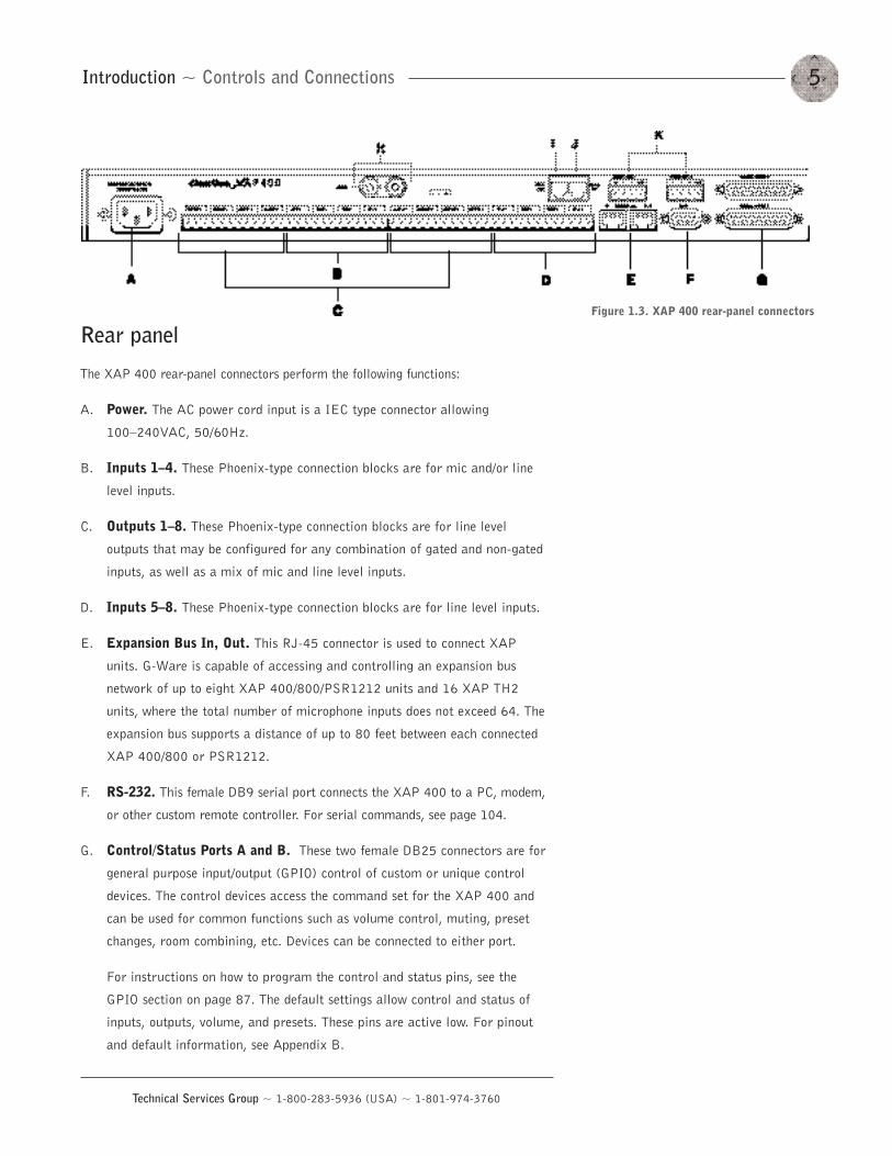
The XAP 400 rear-panel connectors perform the following functions:
A. Power. The AC power cord input is a IEC type connector allowing
100—240VAC, 50/60Hz.
B. Inputs 1—4. These Phoenix-type connection blocks are for mic and/or line
level inputs.
C. Outputs 1—8. These Phoenix-type connection blocks are for line level
outputs that may be configured for any combination of gated and non-gated
inputs, as well as a mix of mic and line level inputs.
D. Inputs 5—8. These Phoenix-type connection blocks are for line level inputs.
E. Expansion Bus In, Out. This RJ-45 connector is used to connect XAP
units. G-Ware is capable of accessing and controlling an expansion bus
network of up to eight XAP 400/800/PSR1212 units and 16 XAP TH2
units, where the total number of microphone inputs does not exceed 64. The
expansion bus supports a distance of up to 80 feet between each connected
XAP 400/800 or PSR1212.
F. RS-232. This female DB9 serial port connects the XAP 400 to a PC, modem,
or other custom remote controller. For serial commands, see page 104.
G. Control/Status Ports A and B. These two female DB25 connectors are for
general purpose input/output (GPIO) control of custom or unique control
devices. The control devices access the command set for the XAP 400 and
can be used for common functions such as volume control, muting, preset
changes, room combining, etc. Devices can be connected to either port.
For instructions on how to program the control and status pins, see the
GPIO section on page 87. The default settings allow control and status of
inputs, outputs, volume, and presets. These pins are active low. For pinout
and default information, see Appendix B.
Figure 1.3. XAP 400 rear-panel connectors
Introduction ~ Networking6
Technical Services Group ~ 1-800-283-5936 (USA) ~ 1-801-974-3760
H. Speaker. This is a 10W power amp connector. A 4—16ž speaker can be
directly connected to the XAP 400, eliminating the need for an external
power amplifier.
I. Telco Line. This RJ-11 connector provides connection of a standard analog
telephone line to the hybrid.
J. Telco Set. This RJ-11 connector allows connection to a standard telephone
set. Tip and ring from the phone line are present at this connector when the
hybrid is off. Tip and ring from the phone line are not present at this point
when the hybrid is on.
K. RS-485 Remote Panel A/B Port. These four-pin Phoenix connector ports
allow you to control the XAP 400 with the ClearOne Control Panel or XAP
IR Remote.
Power is supplied through the RS-485 ports to the remote Control Panels
from the XAP 400. This power is limited to a total of 300mA at 15 volts
for each connector. Over-current protection is provided on the +15V pins to
prevent damage in the event of shorting. External power can be provided to
control devices when more current is required. See page 102 for maximum
cable run distances when using ClearOne Control Panels.
Expansion bus
The digital mix-minus expansion bus (RJ-45 LAN) is used to connect up to eight
XAP 800/400s and 16 XAP TH2 units, where the total number of microphone
inputs does not exceed 64. The maximum distance between interconnected XAP
800/400 or PSR1212 units is 80 feet (24 meters). Connecting a XAP TH2 must not
increase the cable length between two PSR1212s, XAP 800s and/or XAP 400s
beyond 80 feet. ClearOne recommends that category five twisted-pair (10BaseT
LAN) cable be used.
The expansion bus (E-bus) allows audio routing between destinations on the
E-bus network. The E-bus contains 12 independent digital audio buses labeled O—Z
which can route mic or line level inputs in any combination across the E-bus
network. The O—Z buses are divided into two groups (O—R and S—Z) based on their
capabilities and default settings. The E-bus also contains four PA adapt/acoustic
echo cancellation reference buses, four global gating buses, and one control bus.
• O—R buses. These four audio buses are defaulted as the mic mix buses; they
can communicate the NOM count and mic mixing parameters across the
Networking
The latency or propagationdelay is <1ms.��
7Introduction ~ Operational Requirements
Technical Services Group ~ 1-800-283-5936 (USA) ~ 1-801-974-3760
Power
The XAP 400 automatically accommodates voltage requirements of 100—240VAC,
50/60Hz, 15W.
Telephone line
The XAP 400 model operates on a standard analog telephone line and connects to
the telephone system with a standard RJ-11C modular jack. If you do not have an
RJ-11C jack where you want to install your XAP 400, call your telephone company
for installation.
The XAP 400 can be configured to meet compliance requirements of different
countries via the G-Ware software. See page 25.
Operational Requirements
Warning: The country codemust be set correctly in G-Ware to ensure that the
unit operates properly whenconnected to the telco network andthat it complies with the country’stelco requirements. Changing thiscode to a country other than theintended country of operation mightcause the XAP 400 to be non-compliant.
!
network to other XAP 400s. All gated mics are routed to the 0-bus by default.
• S—Z buses. These eight buses are defaulted as auxiliary mix buses. They
are used to route auxiliary audio, such as from a CD player or VCR, to and
from other units on the network. These buses are also used as mic mix buses
when NOM count is not required.
• PA Adapt/Acoustic Echo Cancellation Reference buses. These buses
allow an input from a XAP 400 to reference an output on another linked
XAP 400/800. See PA Adapt and AEC Reference on page 33 for more
information.
• Global Gating Groups A-D buses. These mix-minus buses are defined as
microphone gating groups which support first-mic priority, maximum
number of mics, etc. and work across all linked XAP 400/800s. Unlike the
audio buses, they contain only mic status and gate parameters. See page 41
for more information about gating groups.
• Control bus. The control bus is an independent channel from the E-bus’s
audio channel; it uses a different pair of wires on the same E-bus cable. This
allows control information to pass even if the units are not using the audio
Introduction ~ Operational Requirements8
Technical Services Group ~ 1-800-283-5936 (USA) ~ 1-801-974-3760
Equipment placement
The XAP 400 models are designed for installation in a standard 19-inch equipment
rack. You can also purchase side panels for desktop placement. See Appendix D for a
list of accessories.
Environmental
The XAP 400 can be safely operated in a room with varying temperatures between
32 °F/0 °C and 110 °F/43 °C.
Technical Services Group ~ 1-800-283-5936 (USA) ~ 1-801-974-3760
The XAP 400 is designed for easy installation and setup. All connections are made
through rear-panel connectors. This chapter provides instructions on installing the
units and making initial connections, creating an expansion bus (E-bus) network,
assigning device ID numbers, selecting the mixer mode, and using the LCD menu.
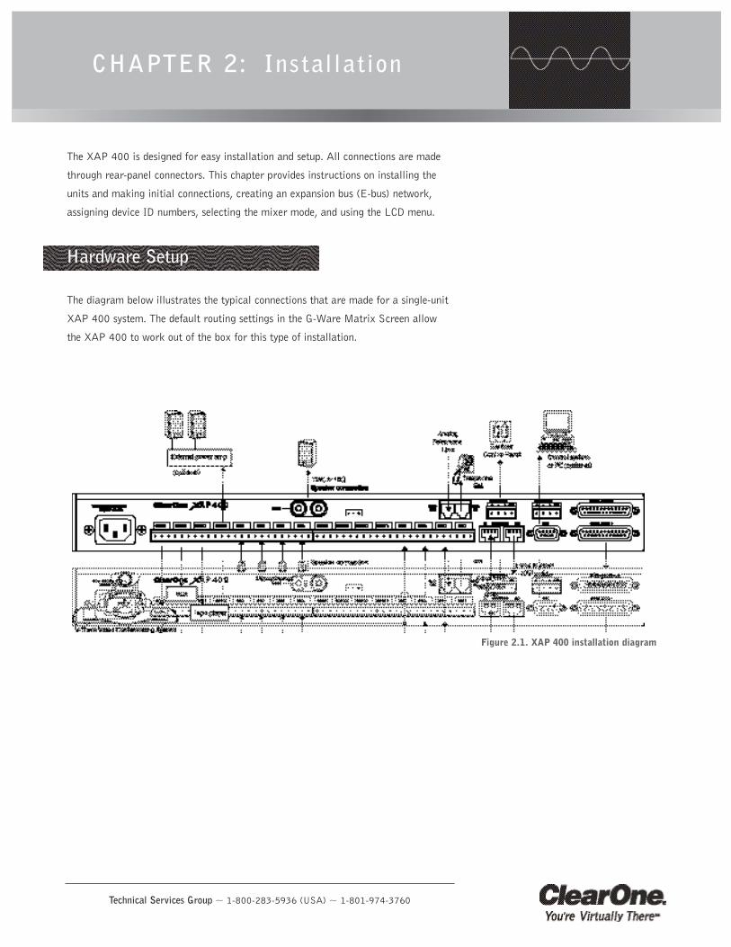
The diagram below illustrates the typical connections that are made for a single-unit
XAP 400 system. The default routing settings in the G-Ware Matrix Screen allow
the XAP 400 to work out of the box for this type of installation.
CHAPTER 2: Installation
Figure 2.1. XAP 400 installation diagram
Hardware Setup
Installation ~ Hardware Setup10
Technical Services Group ~ 1-800-283-5936 (USA) ~ 1-801-974-3760
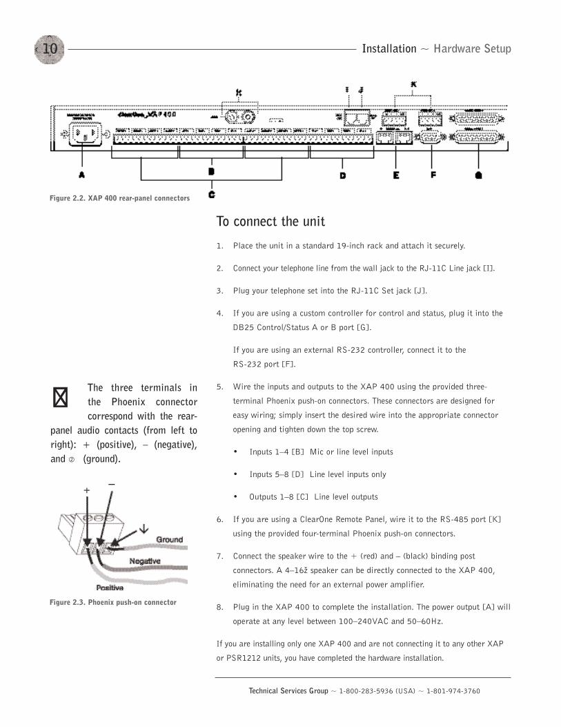
To connect the unit
1. Place the unit in a standard 19-inch rack and attach it securely.
2. Connect your telephone line from the wall jack to the RJ-11C Line jack [I].
3. Plug your telephone set into the RJ-11C Set jack [J].
4. If you are using a custom controller for control and status, plug it into the
DB25 Control/Status A or B port [G].
If you are using an external RS-232 controller, connect it to the
RS-232 port [F].
5. Wire the inputs and outputs to the XAP 400 using the provided three-
terminal Phoenix push-on connectors. These connectors are designed for
easy wiring; simply insert the desired wire into the appropriate connector
opening and tighten down the top screw.
• Inputs 1—4 [B] Mic or line level inputs
• Inputs 5—8 [D] Line level inputs only
• Outputs 1—8 [C] Line level outputs
6. If you are using a ClearOne Remote Panel, wire it to the RS-485 port [K]
using the provided four-terminal Phoenix push-on connectors.
7. Connect the speaker wire to the + (red) and — (black) binding post
connectors. A 4—16ž speaker can be directly connected to the XAP 400,
eliminating the need for an external power amplifier.
8. Plug in the XAP 400 to complete the installation. The power output [A] will
operate at any level between 100—240VAC and 50—60Hz.
If you are installing only one XAP 400 and are not connecting it to any other XAP
or PSR1212 units, you have completed the hardware installation.
Figure 2.2. XAP 400 rear-panel connectors
The three terminals in the Phoenix connectorcorrespond with the rear-
panel audio contacts (from left toright): + (positive), — (negative),and � (ground).
��
Figure 2.3. Phoenix push-on connector
11Installation ~ Networking Units
Technical Services Group ~ 1-800-283-5936 (USA) ~ 1-801-974-3760
Expansion bus connections
Using the Expansion Bus ports (RJ-45), you can connect up to eight XAP 800/400s
and 16 XAP TH2 units, where the total number of microphone inputs does not
exceed 64. Make connections between units in daisy-chain fashion using the short
RJ-45 jumper. If your units are further apart, use category five twisted-pair cable.
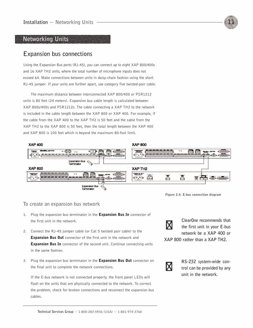
The maximum distance between interconnected XAP 800/400 or PSR1212
units is 80 feet (24 meters). Expansion bus cable length is calculated between
XAP 800s/400s and PSR1212s. The cable connecting a XAP TH2 to the network
is included in the cable length between the XAP 800 or XAP 400. For example, if
the cable from the XAP 400 to the XAP TH2 is 50 feet and the cable from the
XAP TH2 to the XAP 800 is 50 feet, then the total length between the XAP 400
and XAP 800 is 100 feet which is beyond the maximum 80-foot limit.
To create an expansion bus network
1. Plug the expansion bus terminator in the Expansion Bus In connector of
the first unit in the network.
2. Connect the RJ-45 jumper cable (or Cat 5 twisted pair cable) to the
Expansion Bus Out connector of the first unit in the network and
Expansion Bus In connector of the second unit. Continue connecting units
in the same fashion.
3. Plug the expansion bus terminator in the Expansion Bus Out connector on
the final unit to complete the network connections.
If the E-bus network is not connected properly, the front panel LEDs will
flash on the units that are physically connected to the network. To correct
the problem, check for broken connections and reconnect the expansion bus
cables.
Figure 2.4. E-bus connection diagram
Networking Units
ClearOne recommends thatthe first unit in your E-busnetwork be a XAP 400 or
XAP 800 rather than a XAP TH2.
��
RS-232 system-wide con-trol can be provided by anyunit in the network.
��
Installation ~ Networking Units12
Technical Services Group ~ 1-800-283-5936 (USA) ~ 1-801-974-3760
Device IDs
Once your expansion bus connections are made (and if you have more than one
XAP 400 at a site), you need to set up a unique expansion bus device ID number–a
network address–for each XAP 400 on the network. As shipped from the factory,
all XAP 400s default as device ID 0.
To assign device IDs
1. Press the front-panel Enter button, then scroll through the menu until the
System menu is visible.
2. Press Enter, then scroll through the menu until Device ID is visible.
3. Press Enter, then scroll through the eight (0—7) options. When the desired
Device ID is visible, press Enter to select it. (You can also set the Device ID
in the Unit Properties window of G-Ware software see page 25.)
4. Repeat this process for each XAP 400 on the expansion bus network.
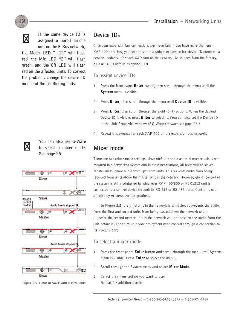
Mixer mode
There are two mixer mode settings: slave (default) and master. A master unit is not
required in a networked system and in most installations, all units will be slaves.
Master units ignore audio from upstream units. This prevents audio from being
received from units above the master unit in the network. However, global control of
the system is still maintained by whichever XAP 400/800 or PSR1212 unit is
connected to a control device through its RS-232 or RS-485 ports. Control is not
affected by master/slave designations.
In Figure 2.5, the third unit in the network is a master. It prevents the audio
from the first and second units from being passed down the network chain.
Likewise the second master unit in the network will not pass on the audio from the
unit before it. The third unit provides system-wide control through a connection to
its RS-232 port.
To select a mixer mode
1. Press the front panel Enter button and scroll through the menu until System
menu is visible. Press Enter to select the menu.
2. Scroll through the System menu and select Mixer Mode.
3. Select the mixer setting you want to use.
Repeat for additional units.
If the same device ID isassigned to more than oneunit on the E-Bus network,
the Meter LED “+12” will flashred, the Mic LED “2” will flashgreen, and the Off LED will flashred on the affected units. To correctthe problem, change the device IDon one of the conflicting units.
��
Figure 2.5. E-bus network with master units
You can also use G-Wareto select a mixer mode.See page 25.
��
13Installation ~ LCD Programming
Technical Services Group ~ 1-800-283-5936 (USA) ~ 1-801-974-3760
The XAP 400’s front panel is intuitive to operate, thanks to its simple interface: a
2x16 character LCD, menu buttons, and a peak-level LED bar meter. Although most
of the XAP 400’s features are programmed with G-Ware software (see page 23), the
front panel can be used for simple adjustments and meter monitoring.
When power is applied to the XAP 400, the LCD panel will first read
INITIALIZING. If an error is displayed, contact technical support. When
initialization is complete, “XAP 400” is displayed on the top line and “Unit 0” is
displayed on the bottom line.
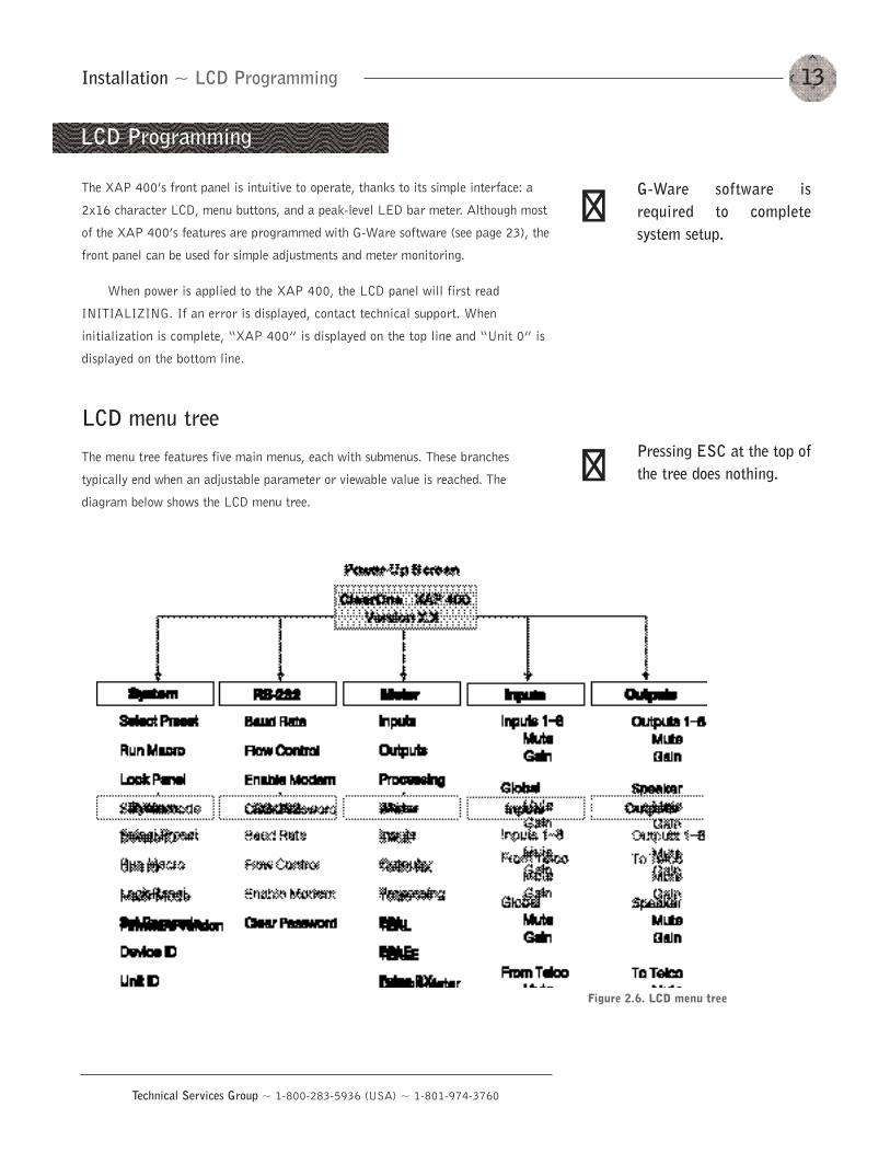
LCD menu tree
The menu tree features five main menus, each with submenus. These branches
typically end when an adjustable parameter or viewable value is reached. The
diagram below shows the LCD menu tree.
LCD Programming
Pressing ESC at the top ofthe tree does nothing.
G-Ware software isrequired to completesystem setup.
��
��
Figure 2.6. LCD menu tree
Installation ~ LCD Programming14
Technical Services Group ~ 1-800-283-5936 (USA) ~ 1-801-974-3760
The five main menus are: System, RS-232, Meter, Inputs, and Outputs. All
submenu items are arranged under these menus. Use the Enter button to select items
and the �and �buttons to scroll through menus and submenus. When the last menu
item is reached, the display scrolls back to the beginning of the list. The Esc button
allows you to back out of the menus.
To adjust a parameter
1. Scroll to the parameter you want to adjust. Press Enter to select the
parameter. The parameter will flash when selected.
2. Adjust the value with the �and �buttons. As the value is adjusted, the
parameter is updated immediately.
3. To store the new value, press Enter. To discard the change and revert back
to the old value, press Esc.
If the Meter button is pressed while a parameter is being adjusted, the LCD
will switch to the Meter menu.
System menu
There are eight system-level parameters (see Figure 2.6): Select Preset, Run Macro,
Lock Panel, Set Passcode, Device ID, Mixer Mode, Unit ID, and Firmware Version.
The latter two are read only; they cannot be changed.
Select Preset
The Select Preset menu item allows for one of 32 preprogrammed presets to be
selected for XAP 400 use. To select a preset, scroll through the numbered presets
(1-32) until the desired preset is visible, then press Enter to run the preset.
Run Macro
The Run Macro menu item allows you to execute a macro. To select a macro, scroll
through the numbered macros (1-255) until the desired macro is visible, then press
Enter to run the macro.
Lock Panel
The front panel may be locked to prevent unauthorized adjustments to the XAP 400.
To lock the front panel, use the �/�buttons to select Lock Panel from the System
menu, and press Enter. Lock Panel selections are Off, On, or On at Timeout. Press
Enter to enable your selection.
15Installation ~ LCD Programming
Technical Services Group ~ 1-800-283-5936 (USA) ~ 1-801-974-3760
To unlock the front panel, attempt to adjust a parameter. The XAP 400 will
prompt for the passcode. Upon entering the fifth character (if entered correctly),
the front panel will unlock. The default passcode for all boxes is ����Enter.
Set Passcode
Once the XAP 400 is unlocked, the passcode may be changed. Before the XAP 400
will allow passcode changes, the new passcode must be entered, then re-entered to
validate the new passcode.
The front panel passcode can also be set (and reset) within G-Ware. See page
26 for more information.
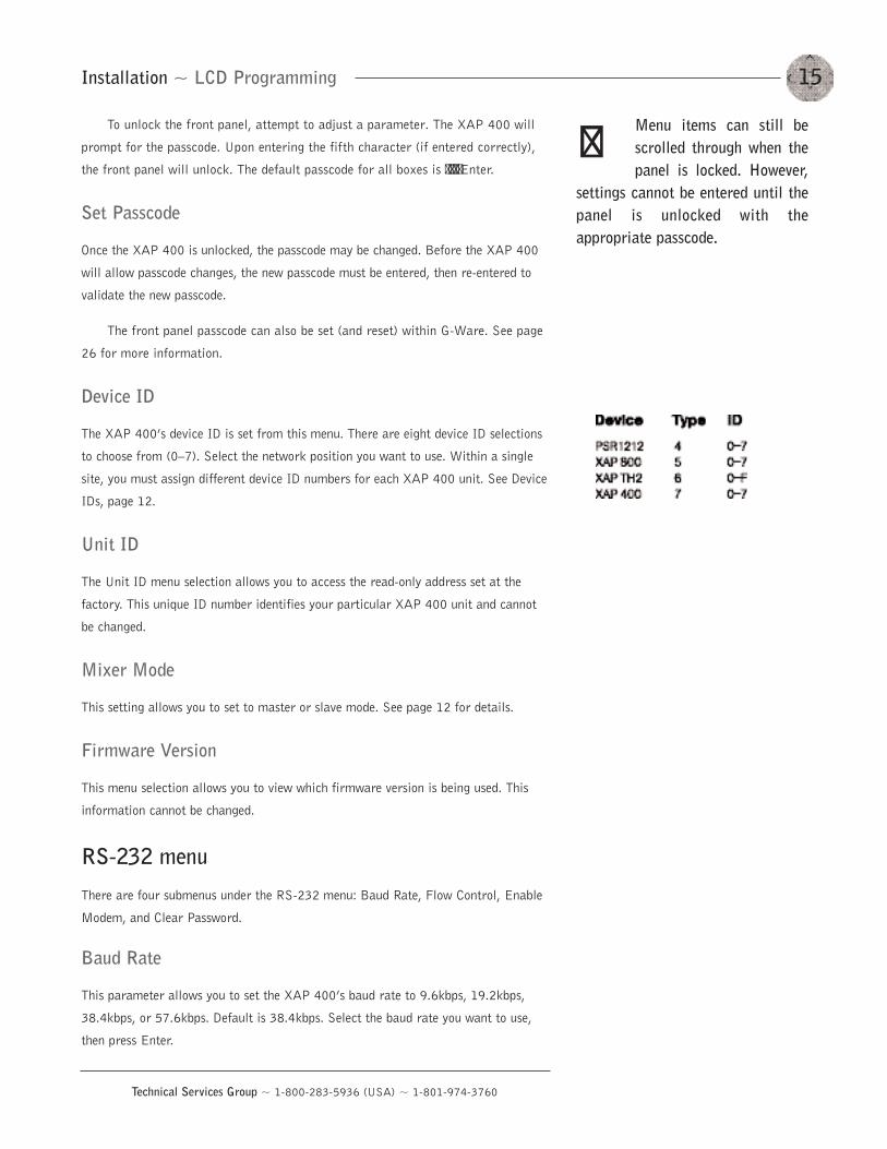
Device ID
The XAP 400’s device ID is set from this menu. There are eight device ID selections
to choose from (0—7). Select the network position you want to use. Within a single
site, you must assign different device ID numbers for each XAP 400 unit. See Device
IDs, page 12.
Unit ID
The Unit ID menu selection allows you to access the read-only address set at the
factory. This unique ID number identifies your particular XAP 400 unit and cannot
be changed.
Mixer Mode
This setting allows you to set to master or slave mode. See page 12 for details.
Firmware Version
This menu selection allows you to view which firmware version is being used. This
information cannot be changed.
RS-232 menu
There are four submenus under the RS-232 menu: Baud Rate, Flow Control, Enable
Modem, and Clear Password.
Baud Rate
This parameter allows you to set the XAP 400’s baud rate to 9.6kbps, 19.2kbps,
38.4kbps, or 57.6kbps. Default is 38.4kbps. Select the baud rate you want to use,
then press Enter.
Menu items can still bescrolled through when thepanel is locked. However,
settings cannot be entered until thepanel is unlocked with theappropriate passcode.
��
Installation ~ LCD Programming16
Technical Services Group ~ 1-800-283-5936 (USA) ~ 1-801-974-3760
Flow Control (hardware)
The XAP 400 uses the RTS and CTS pins on the RS-232 port to regulate the
transmission and reception of data. You can enable or disable flow control on the
front panel of unit and select the flow control type in the Site Properties window of
G-Ware (see page 23). If you select On (default) from the front panel menu, select
Hardware as the flow control type in the Site Properties window. If you disable flow
control on the front panel, select None in the Site Properties window. When None is
selected, the XAP 400 ignores flow control, making the connected external control
device ensure that data is not lost. Software flow control (Xon/Xoff) is supported by
the XAP/PSR units and is only used with a pass-through device, such as a modem.
To avoid communication errors, ClearOne strongly recommends that you
connect all DB9 pins and enable flow control when connecting to a PC.
Enable Modem
This parameter configures the RS-232 port for connection of a modem. When On is
selected, the XAP 400 will send an initialization string to the modem on power-up
and require a password before data transfer is allowed through the port. When Off
(default) is selected, the password is disabled.
To use the XAP 400 with a modem
1. Match the baud rate of the modem to that of the XAP 400.
2. Turn off Serial Echo on the modem.
3. Turn off the modem’s response mode (e.g., no OK messages, ring, etc.).
4. Enable auto-answer on the modem.
Clear Password
This parameter allows you to erase the serial port (modem) password in case it has
been forgotten. Select Yes to keep the current password or No to erase it. Press
Enter to enable your selection.
Meter menu
There are 10 submenus under the Meter menu: Inputs, Outputs, Processing, ERL,
ERLE, Telco RX, Telco TX, TERL, TERLE, and Default Meter. The meter selection
determines what is shown on the front panel peak-level LED display. When the meter
is selected in the LCD menu tree, the LCD displays peak level indications as well.
Use the � and �buttons to select the Meter menu, then scroll through the options and
press Enter when you reach the desired option.
ClearOne recommends thatyou leave Flow Controlenabled.
��
The modem initializationstring can only be set viathe MINIT serial
command (see page 130) or the G-Ware software. It cannot be setthrough the front panel LCD.
��
You can set the modempassword using theMPASS serial command
(see page 131) or in G-Ware (seepage 26).
��
17Installation ~ LCD Programming
Technical Services Group ~ 1-800-283-5936 (USA) ~ 1-801-974-3760
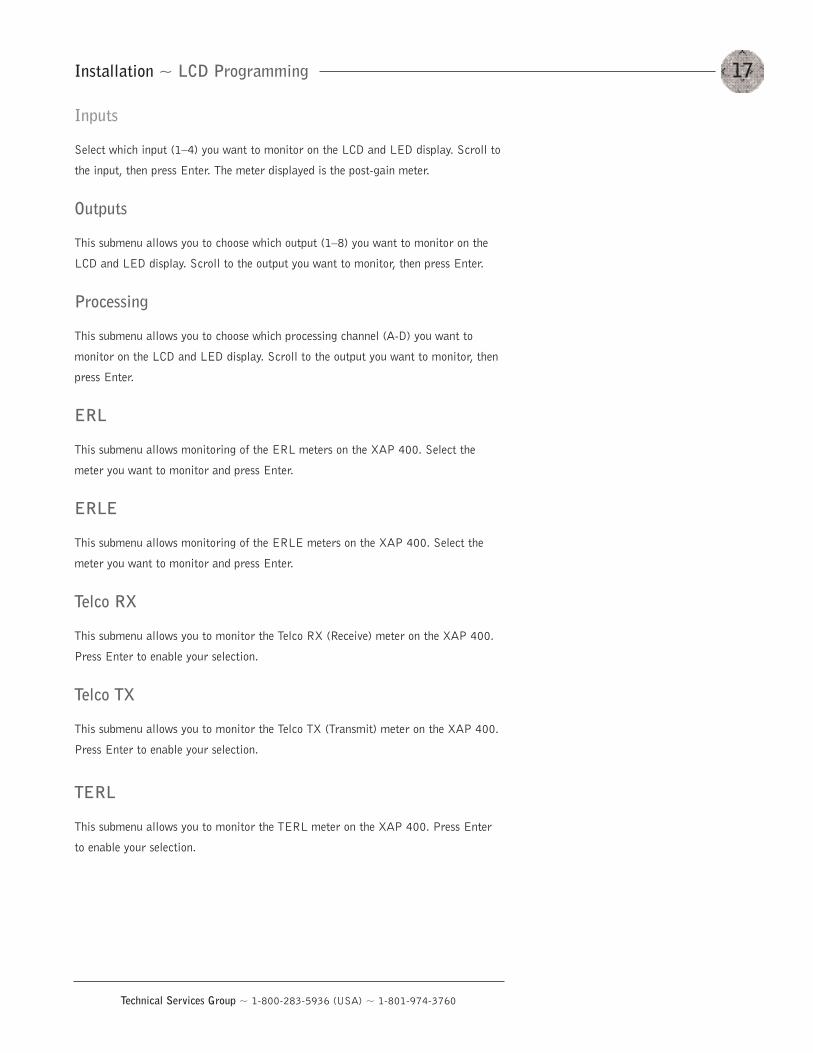
Inputs
Select which input (1—4) you want to monitor on the LCD and LED display. Scroll to
the input, then press Enter. The meter displayed is the post-gain meter.
Outputs
This submenu allows you to choose which output (1—8) you want to monitor on the
LCD and LED display. Scroll to the output you want to monitor, then press Enter.
Processing
This submenu allows you to choose which processing channel (A-D) you want to
monitor on the LCD and LED display. Scroll to the output you want to monitor, then
press Enter.
ERL
This submenu allows monitoring of the ERL meters on the XAP 400. Select the
meter you want to monitor and press Enter.
ERLE
This submenu allows monitoring of the ERLE meters on the XAP 400. Select the
meter you want to monitor and press Enter.
Telco RX
This submenu allows you to monitor the Telco RX (Receive) meter on the XAP 400.
Press Enter to enable your selection.
Telco TX
This submenu allows you to monitor the Telco TX (Transmit) meter on the XAP 400.
Press Enter to enable your selection.
TERL
This submenu allows you to monitor the TERL meter on the XAP 400. Press Enter
to enable your selection.
Installation ~ LCD Programming18
Technical Services Group ~ 1-800-283-5936 (USA) ~ 1-801-974-3760
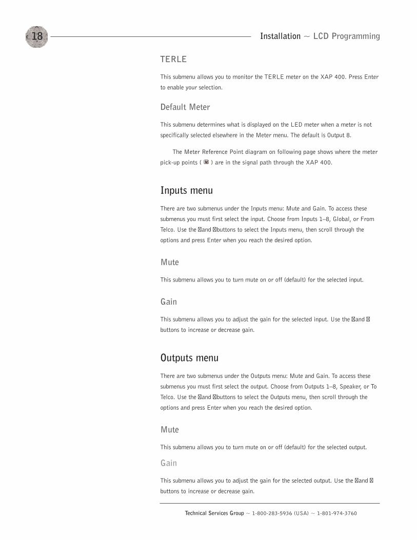
TERLE
This submenu allows you to monitor the TERLE meter on the XAP 400. Press Enter
to enable your selection.
Default Meter
This submenu determines what is displayed on the LED meter when a meter is not
specifically selected elsewhere in the Meter menu. The default is Output 8.
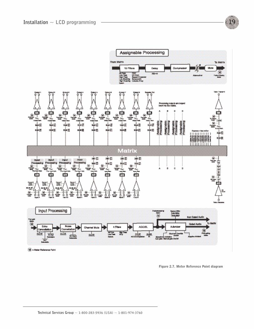
The Meter Reference Point diagram on following page shows where the meter
pick-up points ( ) are in the signal path through the XAP 400.
Inputs menu
There are two submenus under the Inputs menu: Mute and Gain. To access these
submenus you must first select the input. Choose from Inputs 1—8, Global, or From
Telco. Use the � and �buttons to select the Inputs menu, then scroll through the
options and press Enter when you reach the desired option.
Mute
This submenu allows you to turn mute on or off (default) for the selected input.
Gain
This submenu allows you to adjust the gain for the selected input. Use the � and �
buttons to increase or decrease gain.
Outputs menu
There are two submenus under the Outputs menu: Mute and Gain. To access these
submenus you must first select the output. Choose from Outputs 1—8, Speaker, or To
Telco. Use the � and �buttons to select the Outputs menu, then scroll through the
options and press Enter when you reach the desired option.
Mute
This submenu allows you to turn mute on or off (default) for the selected output.
Gain
This submenu allows you to adjust the gain for the selected output. Use the � and �
buttons to increase or decrease gain.
19Installation ~ LCD programming
Technical Services Group ~ 1-800-283-5936 (USA) ~ 1-801-974-3760
Figure 2.7. Meter Reference Point diagram

20
Technical Services Group ~ 1-800-283-5936 (USA) ~ 1-801-974-3760
Technical Services Group ~ 1-800-283-5936 (USA) ~ 1-801-974-3760
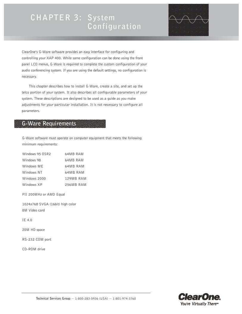
G-Ware software must operate on computer equipment that meets the following
minimum requirements:
Windows 95 OSR2 64MB RAM
Windows 98 64MB RAM
Windows ME 64MB RAM
Windows NT 64MB RAM
Windows 2000 129MB RAM
Windows XP 256MB RAM
PII 200MHz or AMD Equal
1024x768 SVGA (16bit) high color
8M Video card
IE 4.0
20M HD space
RS-232 COM port
CD-ROM drive
CHAPTER 3: System Configuration
G-Ware Requirements
ClearOne’s G-Ware software provides an easy interface for configuring and
controlling your XAP 400. While some configuration can be done using the front
panel LCD menus, G-Ware is required to complete the custom configuration of your
audio conferencing system. If you are using the default settings, no configuration is
necessary.
This chapter describes how to install G-Ware, create a site, and set up the
telco portion of your system. It also describes all configurable parameters of your
system. These descriptions are designed to be used as a guide as you make
adjustments for your particular installation. It is not necessary to configure all
parameters.
System Configuration ~ Installing G-Ware22
Technical Services Group ~ 1-800-283-5936 (USA) ~ 1-801-974-3760
Creating floppy disk copies
Depending upon the computer equipment you have available, you might need to
install G-Ware software from floppy disks rather than the included CD. To do this, a
Disk Copy program is provided in G-Ware that allows you to transfer G-Ware to
floppy disks. You will need a PC with a CD-ROM drive to make the transfer. After
installing G-Ware on the CD-ROM-equipped computer, you can access the Disk Copy
program in the following way:
• From the Windows Start menu, select Programs, ClearOne G-Ware, and
then Create Install Floppy Disks. Follow the onscreen prompts to complete
creation of the floppy disks.
To install G-Ware
1. Boot the PC to the Windows operating system. Ensure that all other
programs or applications are closed. Insert the Audio and Video Products
CD into the CD-ROM drive.
If the Autorun feature is enabled on the PC, the ClearOne Welcome window
opens. Click the Software tab and select G-Ware.
If the Autorun window does not open, open the Windows Start menu and
choose Run. Type “<drive>:\\gentner.exe” where <drive> is the letter of
the CD-ROM drive (e.g., D:\\gentner.exe).
2. At the G-Ware window, click Install G-Ware near the bottom of the window.
3. The InstallShield Wizard opens, and guides you through the Welcome and
License Agreement windows. At the Choose Destination Location window,
choose the directory where G-Ware will be installed. We recommend that
you use the default directory.
4. Click Next or Yes to move to proceed through the windows that follow or
No or Cancel to end the installation process.
5. Follow the onscreen instructions. You must restart your computer once
installation is complete.
The G-Ware Program Folder is now added to your Start menu. You can start
G-Ware through the Start menu or by double-clicking the desktop icon.
Installing G-Ware
To select an alternatedestination directory, clickBrowse and use the Choose
Directory window to find the desiredlocation. Click OK to return to theprevious window.
��
You can also access theDisk Copy program fromthe G-Ware install menu
which is located on the AV ProductsCD (exefiles\gware\setup.exe).
��
Figure 3.1. Desktop icon
23System Configuration ~ Site Setup
Technical Services Group ~ 1-800-283-5936 (USA) ~ 1-801-974-3760
Site Setup
Creating a new site
New site files are created through the Site Properties window in G-Ware. A site file
contains all information about a particular installation including all unit settings and
properties. It also provides G-Ware with the necessary information to communicate
with the site hardware using your PC. Open G-Ware by double clicking the desktop
icon or by selecting G-Ware from the Start menu.
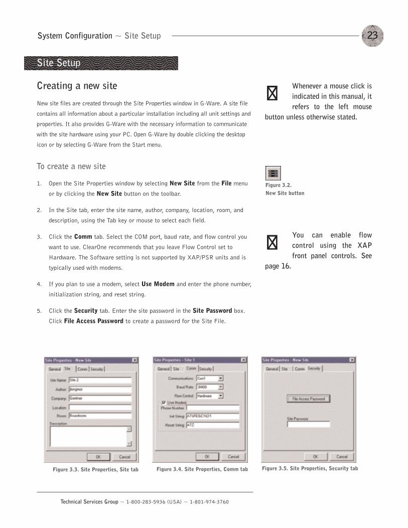
To create a new site
1. Open the Site Properties window by selecting New Site from the File menu
or by clicking the New Site button on the toolbar.
2. In the Site tab, enter the site name, author, company, location, room, and
description, using the Tab key or mouse to select each field.
3. Click the Comm tab. Select the COM port, baud rate, and flow control you
want to use. ClearOne recommends that you leave Flow Control set to
Hardware. The Software setting is not supported by XAP/PSR units and is
typically used with modems.
4. If you plan to use a modem, select Use Modem and enter the phone number,
initialization string, and reset string.
5. Click the Security tab. Enter the site password in the Site Password box.
Click File Access Password to create a password for the Site File.
Whenever a mouse click isindicated in this manual, itrefers to the left mouse
button unless otherwise stated.
Figure 3.2. New Site button
��
Figure 3.3. Site Properties, Site tab Figure 3.4. Site Properties, Comm tab
You can enable flowcontrol using the XAPfront panel controls. See
page 16.
��
Figure 3.5. Site Properties, Security tab
System Configuration ~ Site Setup
Adding a XAP 400
You can add a XAP 400(s) to your site file by connecting to your site and using
G-Ware to automatically create icons for the detected units. Or, you can work offline
and manually add the unit(s) to the site file and connect to the site at a later time.
To open an existing site file, click the Open Site File button or select Open Site from
the File menu.
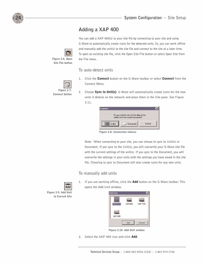
To auto-detect units
1. Click the Connect button on the G-Ware toolbar or select Connect from the
Connect Menu.
2. Choose Sync to Unit(s). G-Ware will automatically create icons for the new
units it detects on the network and place them in the Site pane. See Figure
3.11.
Note: When connecting to your site, you can choose to sync to Unit(s) or
Document. If you sync to the Unit(s), you will overwrite your G-Ware site file
with the current settings of the unit(s). If you sync to the Document, you will
overwrite the settings in your units with the settings you have saved in the site
file. Choosing to sync to Document will also create icons for any new units.
To manually add units
1. If you are working offline, click the Add button on the G-Ware toolbar. This
opens the Add Unit window.
2. Select the XAP 400 icon and click Add.
24
Technical Services Group ~ 1-800-283-5936 (USA) ~ 1-801-974-3760
Figure 3.8. Connection choices
Figure 3.6. OpenSite File button
Figure 3.7. Connect button
Figure 3.9. Add Unitto Current Site
Figure 3.10. Add Unit window
25System Configuration ~ Site Setup
Technical Services Group ~ 1-800-283-5936 (USA) ~ 1-801-974-3760
Configuring Unit Properties
Using the Unit Properties window, you can configure the unit‘s communication and
security properties in addition to general unit properties such as name, type, and
country code. The Unit Properties window automatically opens when you manually
add a unit to the site. You can also right-click the unit icon in the site pane and click
Unit Properties.
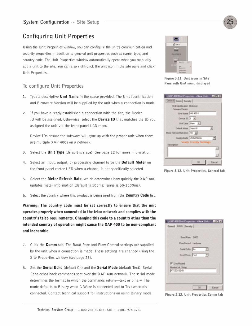
To configure Unit Properties
1. Type a descriptive Unit Name in the space provided. The Unit Identification
and Firmware Version will be supplied by the unit when a connection is made.
2. If you have already established a connection with the site, the Device
ID will be assigned. Otherwise, select the Device ID that matches the ID you
assigned the unit via the front-panel LCD menu.
Device IDs ensure the software will sync up with the proper unit when there
are multiple XAP 400s on a network.
3. Select the Unit Type (default is slave). See page 12 for more information.
4. Select an input, output, or processing channel to be the Default Meter on
the front panel meter LED when a channel is not specifically selected.
5. Select the Meter Refresh Rate, which determines how quickly the XAP 400
updates meter information (default is 100ms; range is 50-1000ms).
6. Select the country where this product is being used from the Country Code list.
Warning: The country code must be set correctly to ensure that the unit
operates properly when connected to the telco network and complies with the
country’s telco requirements. Changing this code to a country other than the
intended country of operation might cause the XAP 400 to be non-compliant
and inoperable.
7. Click the Comm tab. The Baud Rate and Flow Control settings are supplied
by the unit when a connection is made. These settings are changed using the
Site Properties window (see page 23).
8. Set the Serial Echo (default On) and the Serial Mode (default Text). Serial
Echo echos back commands sent over the XAP 400 network. The serial mode
determines the format in which the commands return–text or binary. The
mode defaults to Binary when G-Ware is connected and to Text when dis-
connected. Contact technical support for instructions on using Binary mode.
Figure 3.11. Unit icons in SitePane with Unit menu displayed
Figure 3.12. Unit Properties, General tab
Figure 3.13. Unit Properties Comm tab
System Configuration ~ Site Setup26
Technical Services Group ~ 1-800-283-5936 (USA) ~ 1-801-974-3760
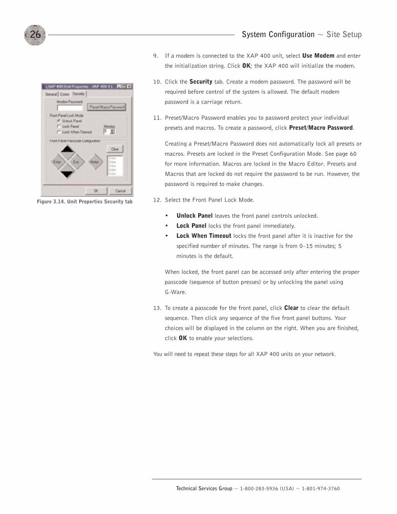
9. If a modem is connected to the XAP 400 unit, select Use Modem and enter
the initialization string. Click OK; the XAP 400 will initialize the modem.
10. Click the Security tab. Create a modem password. The password will be
required before control of the system is allowed. The default modem
password is a carriage return.
11. Preset/Macro Password enables you to password protect your individual
presets and macros. To create a password, click Preset/Macro Password.
Creating a Preset/Macro Password does not automatically lock all presets or
macros. Presets are locked in the Preset Configuration Mode. See page 60
for more information. Macros are locked in the Macro Editor. Presets and
Macros that are locked do not require the password to be run. However, the
password is required to make changes.
12. Select the Front Panel Lock Mode.
• Unlock Panel leaves the front panel controls unlocked.
• Lock Panel locks the front panel immediately.
• Lock When Timeout locks the front panel after it is inactive for the
specified number of minutes. The range is from 0—15 minutes; 5
minutes is the default.
When locked, the front panel can be accessed only after entering the proper
passcode (sequence of button presses) or by unlocking the panel using
G-Ware.
13. To create a passcode for the front panel, click Clear to clear the default
sequence. Then click any sequence of the five front panel buttons. Your
choices will be displayed in the column on the right. When you are finished,
click OK to enable your selections.
You will need to repeat these steps for all XAP 400 units on your network.
Figure 3.14. Unit Properties Security tab
27System Configuration ~ G-Ware Screens
Technical Services Group ~ 1-800-283-5936 (USA) ~ 1-801-974-3760
G-Ware has three modes: Configuration, Preset, and Macro Recorder. Configuration
is used to configure the unit and is the default mode. The Preset and Macro modes
are discussed in Chapter 4: Advanced Configuration. You can switch between modes
by clicking on the corresponding toolbar button. The current mode is displayed on
the status bar.
There are two main configuration screens, the Flow Screen and the Matrix
Screen. All unit configuration and audio routing is accessed through these screens.
Flow Screen
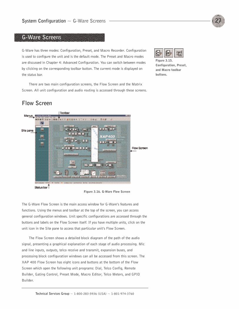
The G-Ware Flow Screen is the main access window for G-Ware’s features and
functions. Using the menus and toolbar at the top of the screen, you can access
general configuration windows. Unit specific configurations are accessed through the
buttons and labels on the Flow Screen itself. If you have multiple units, click on the
unit icon in the Site pane to access that particular unit’s Flow Screen.
The Flow Screen shows a detailed block diagram of the path of the audio
signal, presenting a graphical explanation of each stage of audio processing. Mic
and line inputs, outputs, telco receive and transmit, expansion buses, and
processing block configuration windows can all be accessed from this screen. The
XAP 400 Flow Screen has eight icons and buttons at the bottom of the Flow
Screen which open the following unit programs: Dial, Telco Config, Remote
Builder, Gating Control, Preset Mode, Macro Editor, Telco Meters, and GPIO
Builder.
G-Ware Screens
Figure 3.16. G-Ware Flow Screen
Figure 3.15.Configuration, Preset,and Macro toolbarbuttons.
System Configuration ~ G-Ware Screens28
Technical Services Group ~ 1-800-283-5936 (USA) ~ 1-801-974-3760
Copying and pasting settings
G-Ware has shortcut menus which appear when you right-click a selection or
program window in G-Ware. These shortcut menus provide quick access to options
such as Print, Copy, and Paste that pertain only to that selection or screen region.
Using the Copy and Paste commands, you can copy and paste unit data such as a
single setting or the entire unit’s settings depending on which window you are in. For
example, if you are in the Inputs 1—4 window, using the shortcut menu will allow you
to copy and paste all of the input settings to other inputs. You can also use keyboard
shortcuts (Ctrl+C and Ctrl+V) to copy and paste settings. If you want to apply all
settings of a selected input to the rest of the inputs, select Apply to All.
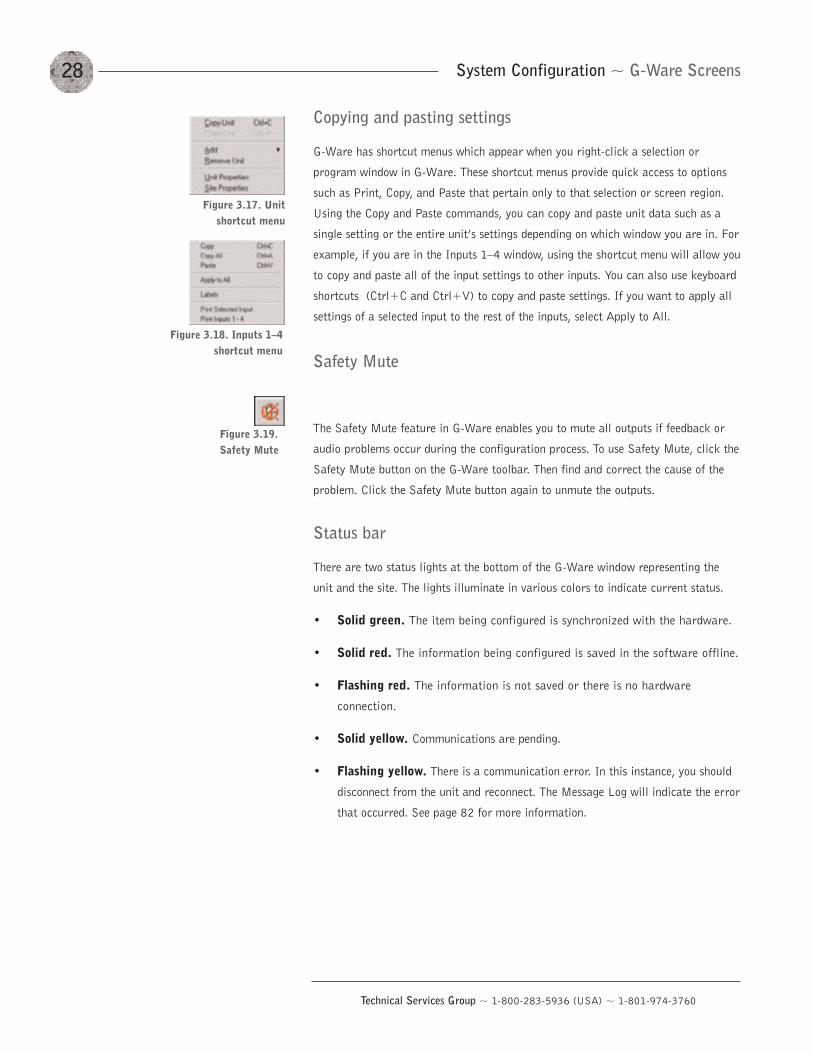
Safety Mute
The Safety Mute feature in G-Ware enables you to mute all outputs if feedback or
audio problems occur during the configuration process. To use Safety Mute, click the
Safety Mute button on the G-Ware toolbar. Then find and correct the cause of the
problem. Click the Safety Mute button again to unmute the outputs.
Status bar
There are two status lights at the bottom of the G-Ware window representing the
unit and the site. The lights illuminate in various colors to indicate current status.
• Solid green. The item being configured is synchronized with the hardware.
• Solid red. The information being configured is saved in the software offline.
• Flashing red. The information is not saved or there is no hardware
connection.
• Solid yellow. Communications are pending.
• Flashing yellow. There is a communication error. In this instance, you should
disconnect from the unit and reconnect. The Message Log will indicate the error
that occurred. See page 82 for more information.
Figure 3.17. Unitshortcut menu
Figure 3.19.Safety Mute
Figure 3.18. Inputs 1—4shortcut menu
29System Configuration ~ G-Ware Screens
Technical Services Group ~ 1-800-283-5936 (USA) ~ 1-801-974-3760
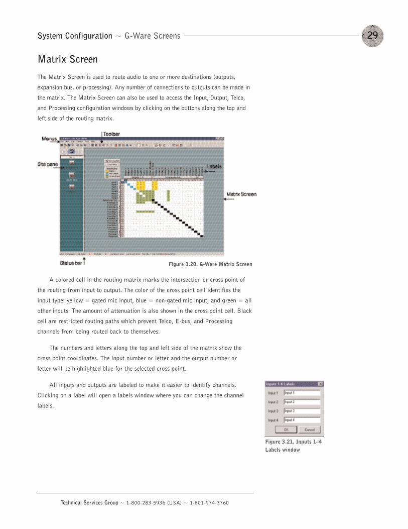
Matrix Screen
The Matrix Screen is used to route audio to one or more destinations (outputs,
expansion bus, or processing). Any number of connections to outputs can be made in
the matrix. The Matrix Screen can also be used to access the Input, Output, Telco,
and Processing configuration windows by clicking on the buttons along the top and
left side of the routing matrix.
A colored cell in the routing matrix marks the intersection or cross point of
the routing from input to output. The color of the cross point cell identifies the
input type: yellow = gated mic input, blue = non-gated mic input, and green = all
other inputs. The amount of attenuation is also shown in the cross point cell. Black
cell are restricted routing paths which prevent Telco, E-bus, and Processing
channels from being routed back to themselves.
The numbers and letters along the top and left side of the matrix show the
cross point coordinates. The input number or letter and the output number or
letter will be highlighted blue for the selected cross point.
All inputs and outputs are labeled to make it easier to identify channels.
Clicking on a label will open a labels window where you can change the channel
labels.
Figure 3.20. G-Ware Matrix Screen
Figure 3.21. Inputs 1—4Labels window
System Configuration ~ Audio Routing30
Technical Services Group ~ 1-800-283-5936 (USA) ~ 1-801-974-3760
Audio is routed in the Matrix Screen (see Figure 3.20 on previous page). To access
the Matrix Screen, click on the Matrix button on the Flow Screen. To return to the
Flow Screen, click the Flow Screen button.
The XAP 400 routing matrix has 25 possible input sources and 26 output
destinations, with level control at each cross point. Any input or combination of
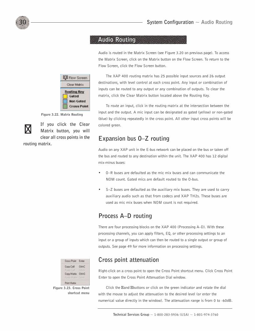
inputs can be routed to any output or any combination of outputs. To clear the
matrix, click the Clear Matrix button located above the Routing Key.
To route an input, click in the routing matrix at the intersection between the
input and the output. A mic input can be designated as gated (yellow) or non-gated
(blue) by clicking repeatedly in the cross point. All other input cross points will be
colored green.
Expansion bus O—Z routing
Audio on any XAP unit in the E-bus network can be placed on the bus or taken off
the bus and routed to any destination within the unit. The XAP 400 has 12 digital
mix-minus buses:
• O—R buses are defaulted as the mic mix buses and can communicate the
NOM count. Gated mics are default routed to the O-bus.
• S—Z buses are defaulted as the auxiliary mix buses. They are used to carry
auxiliary audio such as that from codecs and XAP TH2s. These buses are
used as mic mix buses when NOM count is not required.
Process A—D routing
There are four processing blocks on the XAP 400 (Processing A—D). With these
processing channels, you can apply filters, EQ, or other processing settings to an
input or a group of inputs which can then be routed to a single output or group of
outputs. See page 49 for more information on processing settings.
Cross point attenuation
Right-click on a cross point to open the Cross Point shortcut menu. Click Cross Point
Enter to open the Cross Point Attenuation Dial window.
Click the �and �buttons or click on the green indicator and rotate the dial
with the mouse to adjust the attenuation to the desired level (or enter the
numerical value directly in the window). The attenuation range is from 0 to -60dB.
Audio Routing
Figure 3.22. Matrix Routing
Figure 3.23. Cross Pointshortcut menu
If you click the ClearMatrix button, you willclear all cross points in the
routing matrix.
��
31System Configuration ~ Audio Routing
Technical Services Group ~ 1-800-283-5936 (USA) ~ 1-801-974-3760
Click Close to exit. Note that the level control you have selected for the cross point
is indicated numerically in the matrix.
The Cross Point shortcut menu also allows you to copy and paste the current
Cross Point configuration, including attenuation, to other cross points. You can
copy a single cell or the entire matrix using the shortcut menu options. To copy
and paste a cross point to multiple cross points, press Ctrl+C to copy (or right-
mouse click). Then press Ctrl+V while holding down the left-mouse button and
drag the mouse over the cross points to which you want to copy the settings. Figure 3.24. Cross Point window
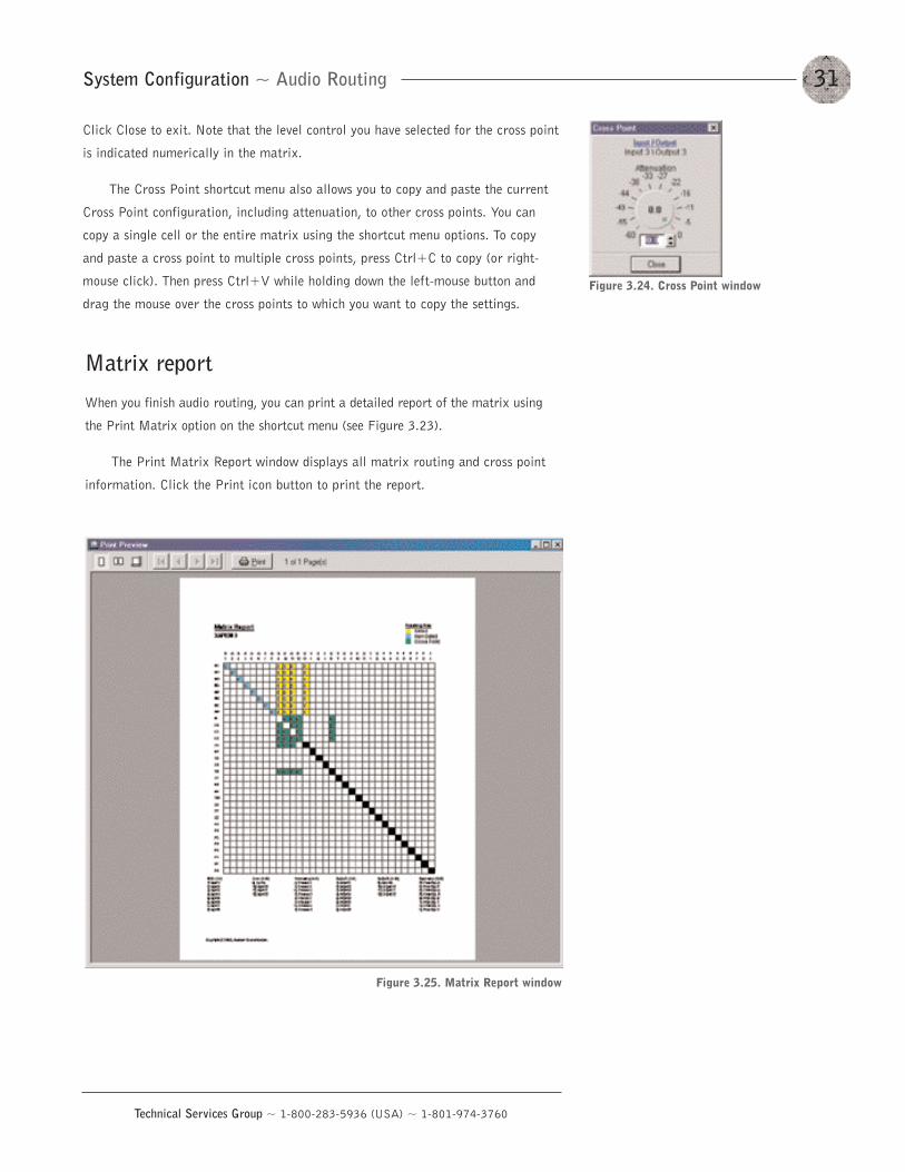
Matrix report
When you finish audio routing, you can print a detailed report of the matrix using
the Print Matrix option on the shortcut menu (see Figure 3.23).
The Print Matrix Report window displays all matrix routing and cross point
information. Click the Print icon button to print the report.
Figure 3.25. Matrix Report window
System Configuration ~ Inputs and Outputs32
Technical Services Group ~ 1-800-283-5936 (USA) ~ 1-801-974-3760
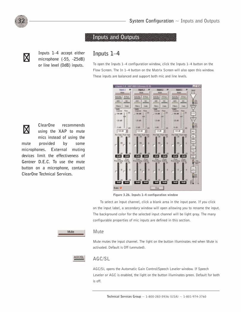
Inputs 1—4
To open the Inputs 1—4 configuration window, click the Inputs 1—4 button on the
Flow Screen. The In 1—4 button on the Matrix Screen will also open this window.
These inputs are balanced and support both mic and line levels.
To select an input channel, click a blank area in the input pane. If you click
on the input label, a secondary window will open allowing you to rename the input.
The background color for the selected input channel will be light gray. The many
configurable properties of mic inputs are defined in this section.
Mute
Mute mutes the input channel. The light on the button illuminates red when Mute is
activated. Default is Off (unmuted).
AGC/SL
AGC/SL opens the Automatic Gain Control/Speech Leveler window. If Speech
Leveler or AGC is enabled, the light on the button illuminates green. Default for both
is off.
Inputs and Outputs
Figure 3.26. Inputs 1—4 configuration window
Inputs 1—4 accept eithermicrophone (-55, -25dB)or line level (0dB) inputs.
��
ClearOne recommendsusing the XAP to mutemics instead of using the
mute provided by somemicrophones. External mutingdevices limit the effectiveness ofGentner D.E.C. To use the mutebutton on a microphone, contactClearOne Technical Services.
��
33System Configuration ~ Inputs and Outputs
Technical Services Group ~ 1-800-283-5936 (USA) ~ 1-801-974-3760
The Speech Leveler is a compander that is optimized for speech audio. It
quickly equalizes the difference in speech levels in the room without bringing up noise.
If you use AGC with the Speech Leveler, set the AGC Response Time to >2 seconds.
AGC adjusts softer and louder input audio to a consistent level that you select
(the target level). The target level range is from -30 to 20dB in 1dB steps. The
default target level is 0dB.
Set the Target Level first, then apply the amount of maximum gain that you
want the AGC to apply to the signal. Maximum gain range is 0 to 18dB in 1dB
steps. The default value is 18dB. AGC occurs after the gain and filter settings in
the audio signal path.
The Active Gain meter reflects the overall gain at any given moment. Click
the white box next to the meter to enable it.
The Response Time adjustment determines the total AGC engage/disengage
response time. The Threshold determines the decibel level at which you want the
AGC to engage. Setting the threshold toward the higher end of the scale (near 0)
reduces background noise to a greater degree. The Response Time is measured in
milliseconds. Target Level and Threshold are both RMS.
P Pwr (Phantom Power)
Phantom Power toggles the phantom power on and off. Phantom power is an
auxiliary power source to power certain types of microphones. The XAP 400’s
phantom power voltage is 24VDC. Default is On.
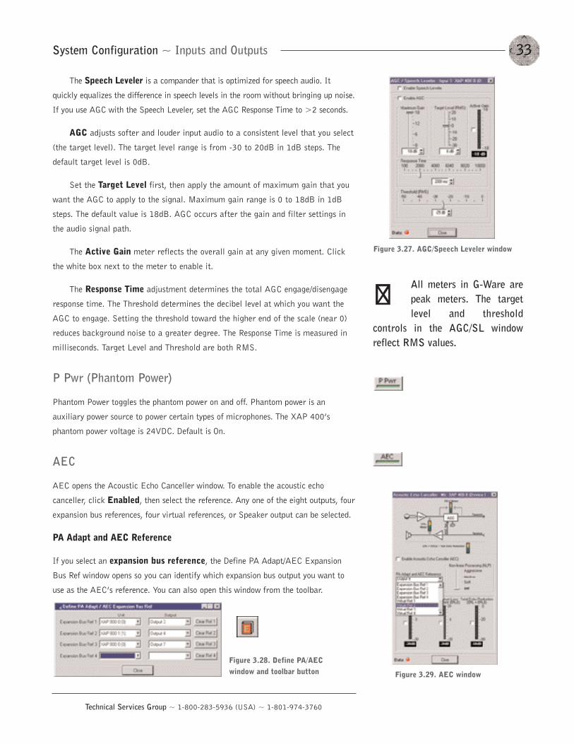
AEC
AEC opens the Acoustic Echo Canceller window. To enable the acoustic echo
canceller, click Enabled, then select the reference. Any one of the eight outputs, four
expansion bus references, four virtual references, or Speaker output can be selected.
PA Adapt and AEC Reference
If you select an expansion bus reference, the Define PA Adapt/AEC Expansion
Bus Ref window opens so you can identify which expansion bus output you want to
use as the AEC’s reference. You can also open this window from the toolbar.
Figure 3.27. AGC/Speech Leveler window
All meters in G-Ware arepeak meters. The targetlevel and threshold
controls in the AGC/SL windowreflect RMS values.
��
Figure 3.29. AEC window
Figure 3.28. Define PA/AECwindow and toolbar button
System Configuration ~ Inputs and Outputs34
Technical Services Group ~ 1-800-283-5936 (USA) ~ 1-801-974-3760
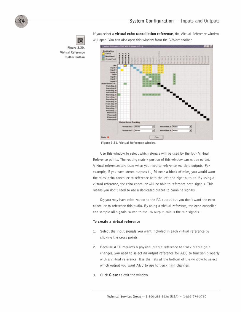
If you select a virtual echo cancellation reference, the Virtual Reference window
will open. You can also open this window from the G-Ware toolbar.
Use this window to select which signals will be used by the four Virtual
Reference points. The routing matrix portion of this window can not be edited.
Virtual references are used when you need to reference multiple outputs. For
example, if you have stereo outputs (L, R) near a block of mics, you would want
the mics’ echo canceller to reference both the left and right outputs. By using a
virtual reference, the echo canceller will be able to reference both signals. This
means you don’t need to use a dedicated output to combine signals.
Or, you may have mics routed to the PA output but you don’t want the echo
canceller to reference this audio. By using a virtual reference, the echo canceller
can sample all signals routed to the PA output, minus the mic signals.
To create a virtual reference
1. Select the input signals you want included in each virtual reference by
clicking the cross points.
2. Because AEC requires a physical output reference to track output gain
changes, you need to select an output reference for AEC to function properly
with a virtual reference. Use the lists at the bottom of the window to select
which output you want AEC to use to track gain changes.
3. Click Close to exit the window.
Figure 3.31. Virtual Reference window.
Figure 3.30. Virtual Reference
toolbar button
35System Configuration ~ Inputs and Outputs
Technical Services Group ~ 1-800-283-5936 (USA) ~ 1-801-974-3760
Non-linear Processing (NLP)
The Non-linear Processing (NLP) feature increases the power of echo cancellation
for difficult acoustical environments. NLP features four settings: Soft (6dB),
Medium (12dB), Aggressive (18dB), and Off. Use NLP with care; corresponding
trade-offs can include suppression and half-duplex operation. Default is Soft.
Meters
The Echo Return Loss (ERL) meter on the Acoustic Echo Canceller window shows
the coupling between the reference signal and the input to the echo canceller–the
ratio of the two levels. It is an average meter that updates only when a signal is
present.
The Echo Return Loss Enhancement (ERLE) meter shows the loss through the
echo cancellation and non-linear processing chain–the ratio of the two levels. It is
an average meter that updates only when a signal is present.
The Total Echo Reduction meter shows the total ERL and ERLE reduction, in
decibels. It is an average meter that updates only when a signal is present.
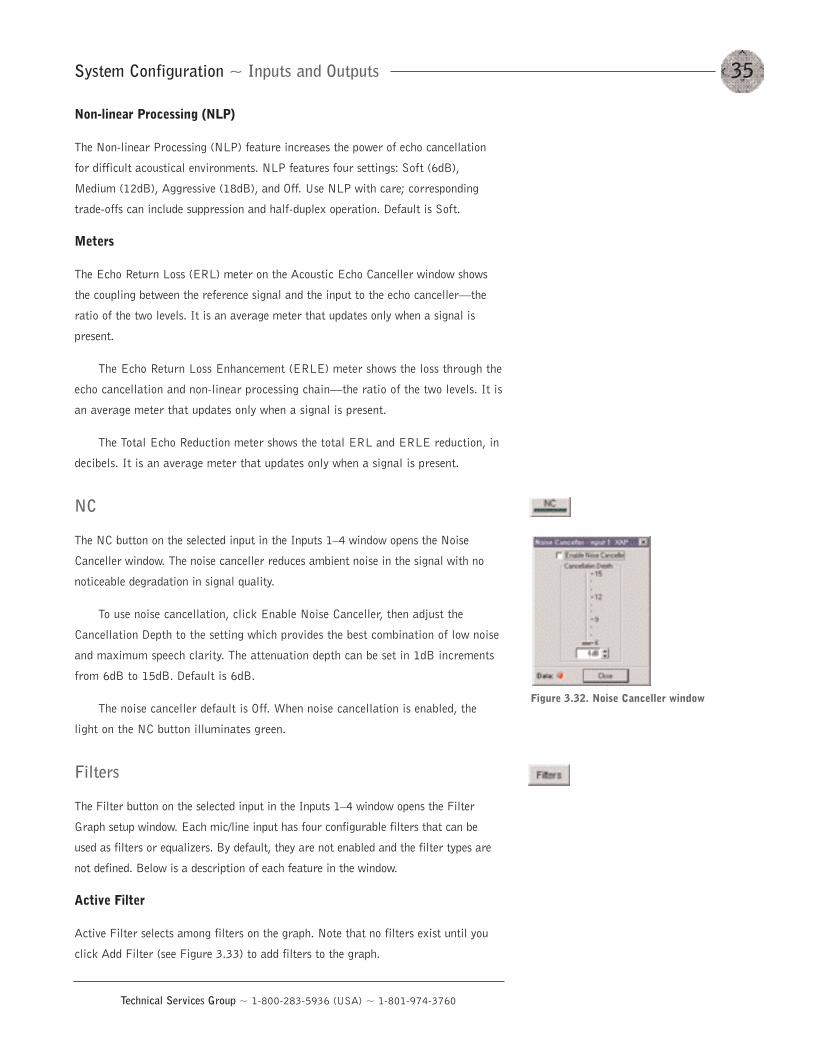
NC
The NC button on the selected input in the Inputs 1—4 window opens the Noise
Canceller window. The noise canceller reduces ambient noise in the signal with no
noticeable degradation in signal quality.
To use noise cancellation, click Enable Noise Canceller, then adjust the
Cancellation Depth to the setting which provides the best combination of low noise
and maximum speech clarity. The attenuation depth can be set in 1dB increments
from 6dB to 15dB. Default is 6dB.
The noise canceller default is Off. When noise cancellation is enabled, the
light on the NC button illuminates green.
Filters
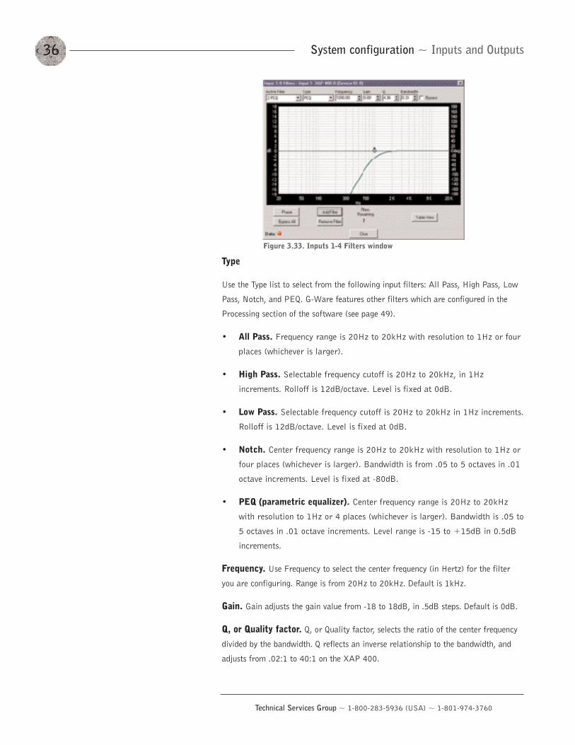
The Filter button on the selected input in the Inputs 1—4 window opens the Filter
Graph setup window. Each mic/line input has four configurable filters that can be
used as filters or equalizers. By default, they are not enabled and the filter types are
not defined. Below is a description of each feature in the window.
Active Filter
Active Filter selects among filters on the graph. Note that no filters exist until you
click Add Filter (see Figure 3.33) to add filters to the graph.
Figure 3.32. Noise Canceller window
System configuration ~ Inputs and Outputs36
Technical Services Group ~ 1-800-283-5936 (USA) ~ 1-801-974-3760
Type
Use the Type list to select from the following input filters: All Pass, High Pass, Low
Pass, Notch, and PEQ. G-Ware features other filters which are configured in the
Processing section of the software (see page 49).
• All Pass. Frequency range is 20Hz to 20kHz with resolution to 1Hz or four
places (whichever is larger).
• High Pass. Selectable frequency cutoff is 20Hz to 20kHz, in 1Hz
increments. Rolloff is 12dB/octave. Level is fixed at 0dB.
• Low Pass. Selectable frequency cutoff is 20Hz to 20kHz in 1Hz increments.
Rolloff is 12dB/octave. Level is fixed at 0dB.
• Notch. Center frequency range is 20Hz to 20kHz with resolution to 1Hz or
four places (whichever is larger). Bandwidth is from .05 to 5 octaves in .01
octave increments. Level is fixed at -80dB.
• PEQ (parametric equalizer). Center frequency range is 20Hz to 20kHz
with resolution to 1Hz or 4 places (whichever is larger). Bandwidth is .05 to
5 octaves in .01 octave increments. Level range is -15 to +15dB in 0.5dB
increments.
Frequency. Use Frequency to select the center frequency (in Hertz) for the filter
you are configuring. Range is from 20Hz to 20kHz. Default is 1kHz.
Gain. Gain adjusts the gain value from -18 to 18dB, in .5dB steps. Default is 0dB.
Q, or Quality factor. Q, or Quality factor, selects the ratio of the center frequency
divided by the bandwidth. Q reflects an inverse relationship to the bandwidth, and
adjusts from .02:1 to 40:1 on the XAP 400.
Figure 3.33. Inputs 1-4 Filters window
37System Configuration ~ Inputs and Outputs
Technical Services Group ~ 1-800-283-5936 (USA) ~ 1-801-974-3760
Bandwidth. Bandwidth establishes the difference between the upper and lower
points of a filter’s audio passband.
Bypass. The Bypass box, when selected, bypasses the selected filter.
Phase. Phase generates–on the graph–the phase relationship of the graphed
frequency response.
Bypass All. Bypass All bypasses all filters.
Add Filter. Add Filter adds a filter to the graph, centered at 1kHz and 0dB.
Remove Filter. Remove Filter removes the selected node from the graph.
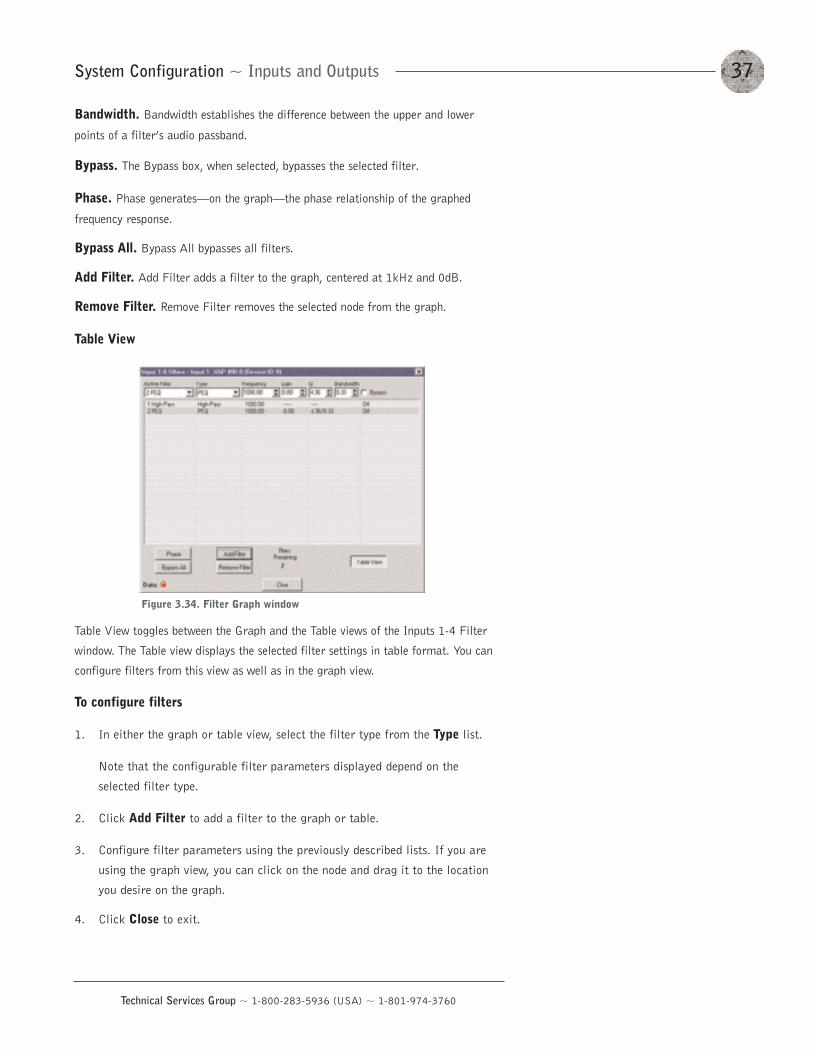
Table View
Table View toggles between the Graph and the Table views of the Inputs 1-4 Filter
window. The Table view displays the selected filter settings in table format. You can
configure filters from this view as well as in the graph view.
To configure filters
1. In either the graph or table view, select the filter type from the Type list.
Note that the configurable filter parameters displayed depend on the
selected filter type.
2. Click Add Filter to add a filter to the graph or table.
3. Configure filter parameters using the previously described lists. If you are
using the graph view, you can click on the node and drag it to the location
you desire on the graph.
4. Click Close to exit.
Figure 3.34. Filter Graph window
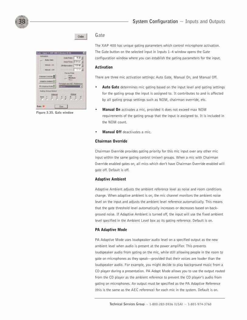
Gate
The XAP 400 has unique gating parameters which control microphone activation.
The Gate button on the selected input in Inputs 1—4 window opens the Gate
configuration window where you can establish the gating parameters for the input.
Activation
There are three mic activation settings: Auto Gate, Manual On, and Manual Off.
• Auto Gate determines mic gating based on the input level and gating settings
for the gating group the input is assigned to. It contributes to and is affected
by all gating group settings such as NOM, chairman override, etc.
• Manual On activates a mic, provided it does not exceed max NOM
requirements of the gating group that the input is assigned to. It is included in
the NOM count.
• Manual Off deactivates a mic.
Chairman Override
Chairman Override provides gating priority for this mic input over any other mic
input within the same gating control (mixer) groups. When a mic with Chairman
Override enabled gates on, all mics which don’t have Chairman Override enabled will
gate off. Default is off.
Adaptive Ambient
Adaptive Ambient adjusts the ambient reference level as noise and room conditions
change. When adaptive ambient is on, the mic channel monitors the ambient noise
level on the input and adjusts the ambient level reference automatically. This means
that the gate threshold level automatically increases or decreases based on back-
ground noise. If Adaptive Ambient is turned off, the input will use the fixed ambient
level specified in the Ambient Level box as its gating reference. Default is on.
PA Adaptive Mode
PA Adaptive Mode uses loudspeaker audio level on a specified output as the new
ambient level when audio is present at the power amplifier. This prevents
loudspeaker audio from gating on the mic, while still allowing people in the room to
gate on microphones as they speak–provided that their voices are louder than the
loudspeaker audio. For example, you might decide to play background music from a
CD player during a presentation. PA Adapt Mode allows you to use the output routed
from the CD player as the ambient reference to prevent the CD player’s audio from
gating on microphones. An output must be specified as the PA Adaptive Reference
(this is the same as the AEC reference) for each mic in the system. Default is on.
System Configuration ~ Inputs and Outputs38
Technical Services Group ~ 1-800-283-5936 (USA) ~ 1-801-974-3760
Figure 3.35. Gate window
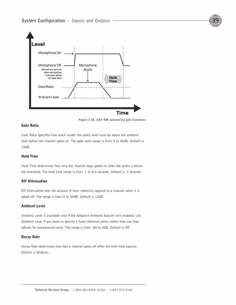
39System Configuration ~ Inputs and Outputs
Technical Services Group ~ 1-800-283-5936 (USA) ~ 1-801-974-3760
Gate Ratio
Gate Ratio specifies how much louder the audio level must be above the ambient
level before the channel gates on. The gate ratio range is from 0 to 50dB. Default is
15dB.
Hold Time
Hold Time determines how long the channel stays gated on after the audio is below
the threshold. The hold time range is from .1 to 8.0 seconds. Default is .3 seconds.
Off Attenuation
Off Attenuation sets the amount of level reduction applied to a channel when it is
gated off. The range is from 0 to 50dB. Default is 12dB.
Ambient Level
Ambient Level is available only if the Adaptive Ambient feature isn’t enabled. Use
Ambient Level if you want to specify a fixed reference point rather than one that
adjusts for background noise. The range is from -80 to 0dB. Default is Off.
Decay Rate
Decay Rate determines how fast a channel gates off after the hold time expires.
Default is Medium.
Figure 3.36. XAP 400 automixing gate functions
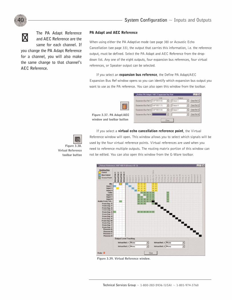
System Configuration ~ Inputs and Outputs40
Technical Services Group ~ 1-800-283-5936 (USA) ~ 1-801-974-3760
PA Adapt and AEC Reference
When using either the PA Adaptive mode (see page 38) or Acoustic Echo
Cancellation (see page 33), the output that carries this information, i.e. the reference
output, must be defined. Select the PA Adapt and AEC Reference from the drop-
down list. Any one of the eight outputs, four expansion bus references, four virtual
references, or Speaker output can be selected.
If you select an expansion bus reference, the Define PA Adapt/AEC
Expansion Bus Ref window opens so you can identify which expansion bus output you
want to use as the PA reference. You can also open this window from the toolbar.
If you select a virtual echo cancellation reference point, the Virtual
Reference window will open. This window allows you to select which signals will be
used by the four virtual reference points. Virtual references are used when you
need to reference multiple outputs. The routing matrix portion of this window can
not be edited. You can also open this window from the G-Ware toolbar.
The PA Adapt Referenceand AEC Reference are thesame for each channel. If
you change the PA Adapt Referencefor a channel, you will also makethe same change to that channel’sAEC Reference.
��
Figure 3.37. PA Adapt/AECwindow and toolbar button
Figure 3.39. Virtual Reference window.
Figure 3.38. Virtual Reference
toolbar button
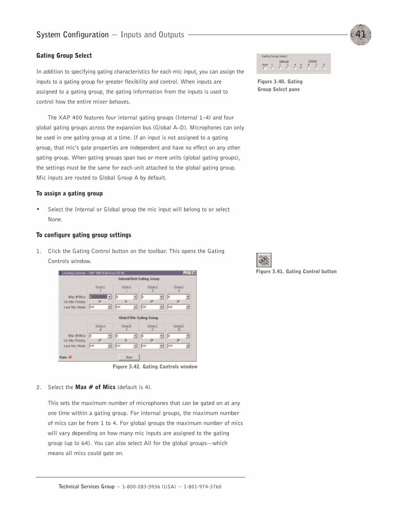
41System Configuration ~ Inputs and Outputs
Technical Services Group ~ 1-800-283-5936 (USA) ~ 1-801-974-3760
Gating Group Select
In addition to specifying gating characteristics for each mic input, you can assign the
inputs to a gating group for greater flexibility and control. When inputs are
assigned to a gating group, the gating information from the inputs is used to
control how the entire mixer behaves.
The XAP 400 features four internal gating groups (Internal 1—4) and four
global gating groups across the expansion bus (Global A—D). Microphones can only
be used in one gating group at a time. If an input is not assigned to a gating
group, that mic’s gate properties are independent and have no effect on any other
gating group. When gating groups span two or more units (global gating groups),
the settings must be the same for each unit attached to the global gating group.
Mic inputs are routed to Global Group A by default.
To assign a gating group
• Select the Internal or Global group the mic input will belong to or select
None.
To configure gating group settings
1. Click the Gating Control button on the toolbar. This opens the Gating
Controls window.
2. Select the Max # of Mics (default is 4).
This sets the maximum number of microphones that can be gated on at any
one time within a gating group. For internal groups, the maximum number
of mics can be from 1 to 4. For global groups the maximum number of mics
will vary depending on how many mic inputs are assigned to the gating
group (up to 64). You can also select All for the global groups–which
means all mics could gate on.
Figure 3.40. Gating Group Select pane
Figure 3.41. Gating Control button
Figure 3.42. Gating Controls window
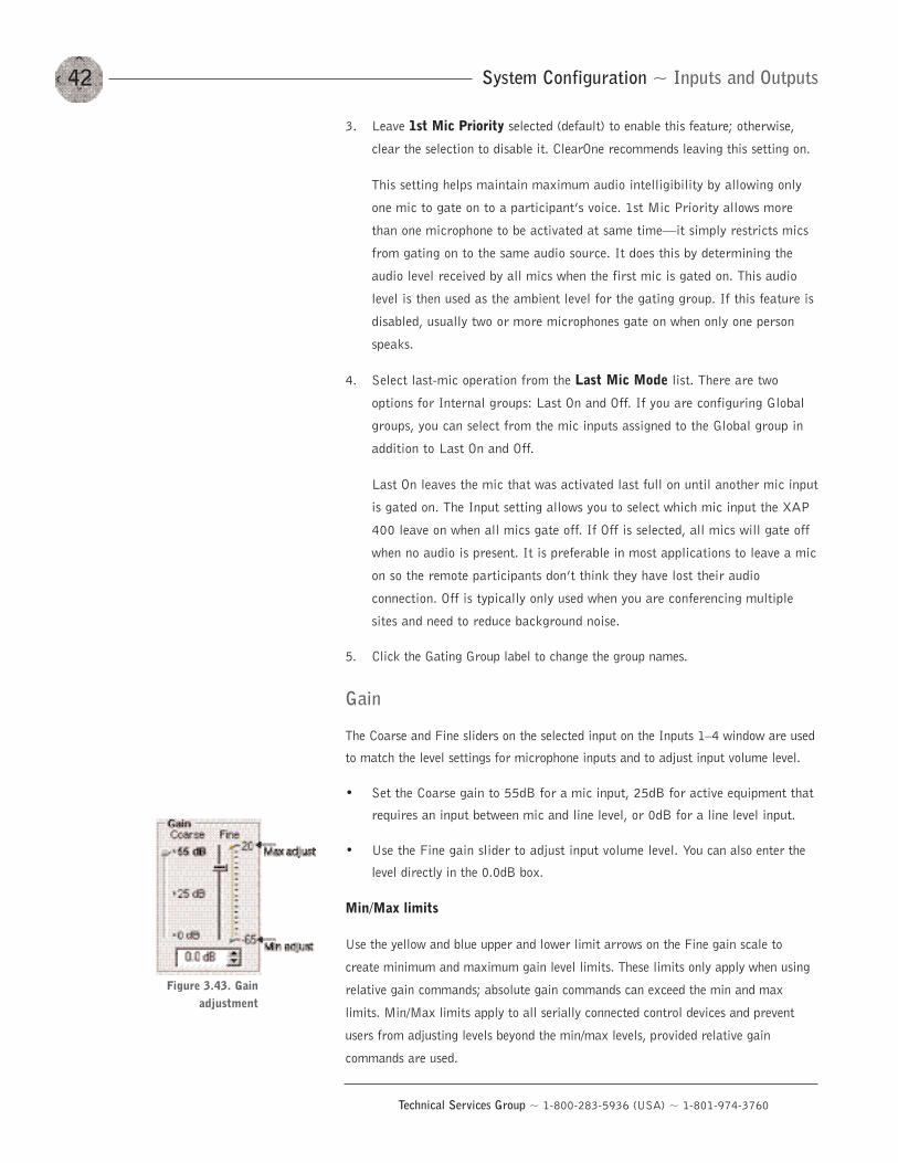
System Configuration ~ Inputs and Outputs42
Technical Services Group ~ 1-800-283-5936 (USA) ~ 1-801-974-3760
3. Leave 1st Mic Priority selected (default) to enable this feature; otherwise,
clear the selection to disable it. ClearOne recommends leaving this setting on.
This setting helps maintain maximum audio intelligibility by allowing only
one mic to gate on to a participant’s voice. 1st Mic Priority allows more
than one microphone to be activated at same time–it simply restricts mics
from gating on to the same audio source. It does this by determining the
audio level received by all mics when the first mic is gated on. This audio
level is then used as the ambient level for the gating group. If this feature is
disabled, usually two or more microphones gate on when only one person
speaks.
4. Select last-mic operation from the Last Mic Mode list. There are two
options for Internal groups: Last On and Off. If you are configuring Global
groups, you can select from the mic inputs assigned to the Global group in
addition to Last On and Off.
Last On leaves the mic that was activated last full on until another mic input
is gated on. The Input setting allows you to select which mic input the XAP
400 leave on when all mics gate off. If Off is selected, all mics will gate off
when no audio is present. It is preferable in most applications to leave a mic
on so the remote participants don’t think they have lost their audio
connection. Off is typically only used when you are conferencing multiple
sites and need to reduce background noise.
5. Click the Gating Group label to change the group names.
Gain
The Coarse and Fine sliders on the selected input on the Inputs 1—4 window are used
to match the level settings for microphone inputs and to adjust input volume level.
• Set the Coarse gain to 55dB for a mic input, 25dB for active equipment that
requires an input between mic and line level, or 0dB for a line level input.
• Use the Fine gain slider to adjust input volume level. You can also enter the
level directly in the 0.0dB box.
Min/Max limits
Use the yellow and blue upper and lower limit arrows on the Fine gain scale to
create minimum and maximum gain level limits. These limits only apply when using
relative gain commands; absolute gain commands can exceed the min and max
limits. Min/Max limits apply to all serially connected control devices and prevent
users from adjusting levels beyond the min/max levels, provided relative gain
commands are used.
Figure 3.43. Gainadjustment
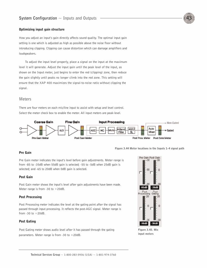
43System Configuration ~ Inputs and Outputs
Technical Services Group ~ 1-800-283-5936 (USA) ~ 1-801-974-3760
Optimizing input gain structure
How you adjust an input’s gain directly affects sound quality. The optimal input gain
setting is one which is adjusted as high as possible above the noise floor without
introducing clipping. Clipping can cause distortion which can damage amplifiers and
loudspeakers.
To adjust the input level properly, place a signal on the input at the maximum
level it will generate. Adjust the input gain until the peak level of the input, as
shown on the Input meter, just begins to enter the red (clipping) zone, then reduce
the gain slightly until peaks no longer climb into the red zone. This setting will
ensure that the XAP 400 maximizes the signal-to-noise ratio without clipping the
signal.
Meters
There are four meters on each mic/line input to assist with setup and level control.
Select the meter check box to enable the meter. All input meters are peak-level.
Pre Gain
Pre Gain meter indicates the input’s level before gain adjustments. Meter range isfrom -85 to -35dB when 55dB gain is selected; -55 to -5dB when 25dB gain isselected; and -65 to 20dB when 0dB gain is selected.
Post Gain
Post Gain meter shows the input’s level after gain adjustments have been made.Meter range is from -30 to +20dB.
Post Processing
Post Processing meter indicates the level at the gating point after the signal haspassed through input processing. It reflects the post-AGC signal. Meter range isfrom -30 to +20dB.
Post Gating
Post Gating meter shows audio level after it has passed through the gating
parameters. Meter range is from -30 to +20dB.
Figure 3.44 Meter locations in the Inputs 1—4 signal path
Figure 3.45. Micinput meters
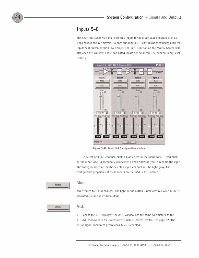
Inputs 5—8
The XAP 400 supports 4 line level only inputs for auxiliary audio sources such as
video codecs and CD players. To open the Inputs 5—8 configuration window, click the
Inputs 5—8 button on the Flow Screen. The In 5—8 button on the Matrix Screen will
also open this window. These non-gated inputs are balanced. The nominal input level
is 0dBu.
To select an input channel, click a blank area in the input pane. If you click
on the input label, a secondary window will open allowing you to rename the input.
The background color for the selected input channel will be light gray. The
configurable properties of these inputs are defined in this section.
Mute
Mute mutes the input channel. The light on the button illuminates red when Mute is
activated. Default is off (unmuted).
AGC
AGC opens the AGC window. The AGC window has the same parameters as the
AGC/SL window with the exception of Enable Speech Leveler. See page 32. The
button light illuminates green when AGC is enabled.
System Configuration ~ Inputs and Outputs44
Technical Services Group ~ 1-800-283-5936 (USA) ~ 1-801-974-3760
Figure 3.46. Input 5-8 Configuration window
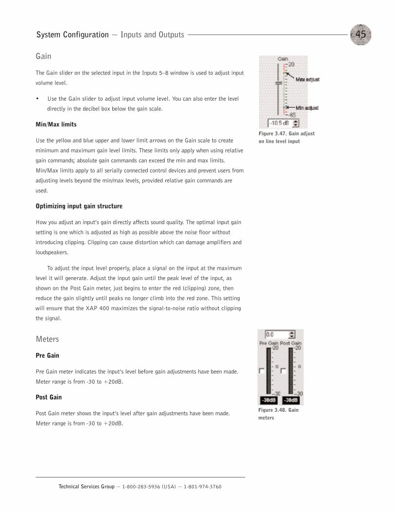
45System Configuration ~ Inputs and Outputs
Technical Services Group ~ 1-800-283-5936 (USA) ~ 1-801-974-3760
Gain
The Gain slider on the selected input in the Inputs 5—8 window is used to adjust input
volume level.
• Use the Gain slider to adjust input volume level. You can also enter the level
directly in the decibel box below the gain scale.
Min/Max limits
Use the yellow and blue upper and lower limit arrows on the Gain scale to create
minimum and maximum gain level limits. These limits only apply when using relative
gain commands; absolute gain commands can exceed the min and max limits.
Min/Max limits apply to all serially connected control devices and prevent users from
adjusting levels beyond the min/max levels, provided relative gain commands are
used.
Optimizing input gain structure
How you adjust an input’s gain directly affects sound quality. The optimal input gain
setting is one which is adjusted as high as possible above the noise floor without
introducing clipping. Clipping can cause distortion which can damage amplifiers and
loudspeakers.
To adjust the input level properly, place a signal on the input at the maximum
level it will generate. Adjust the input gain until the peak level of the input, as
shown on the Post Gain meter, just begins to enter the red (clipping) zone, then
reduce the gain slightly until peaks no longer climb into the red zone. This setting
will ensure that the XAP 400 maximizes the signal-to-noise ratio without clipping
the signal.
Meters
Pre Gain
Pre Gain meter indicates the input’s level before gain adjustments have been made.
Meter range is from -30 to +20dB.
Post Gain
Post Gain meter shows the input’s level after gain adjustments have been made.
Meter range is from -30 to +20dB.
Figure 3.47. Gain adjuston line level input
Figure 3.48. Gainmeters
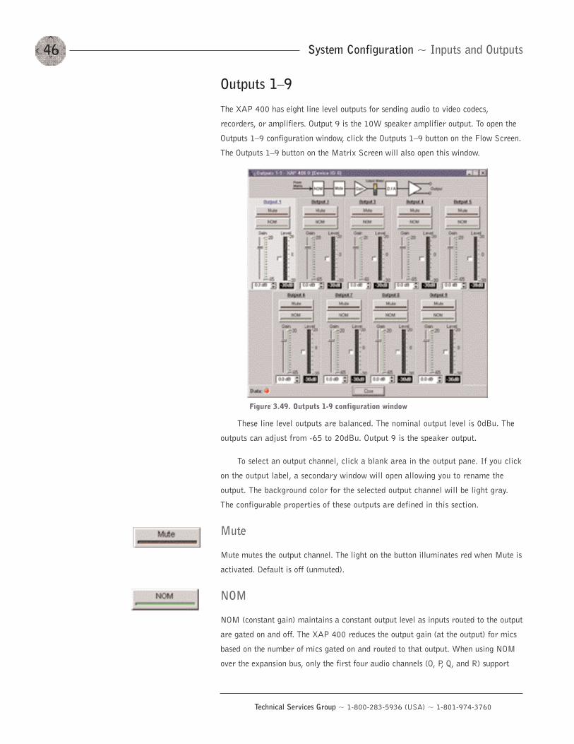
Outputs 1—9
The XAP 400 has eight line level outputs for sending audio to video codecs,
recorders, or amplifiers. Output 9 is the 10W speaker amplifier output. To open the
Outputs 1—9 configuration window, click the Outputs 1—9 button on the Flow Screen.
The Outputs 1—9 button on the Matrix Screen will also open this window.
These line level outputs are balanced. The nominal output level is 0dBu. The
outputs can adjust from -65 to 20dBu. Output 9 is the speaker output.
To select an output channel, click a blank area in the output pane. If you click
on the output label, a secondary window will open allowing you to rename the
output. The background color for the selected output channel will be light gray.
The configurable properties of these outputs are defined in this section.
Mute
Mute mutes the output channel. The light on the button illuminates red when Mute is
activated. Default is off (unmuted).
NOM
NOM (constant gain) maintains a constant output level as inputs routed to the output
are gated on and off. The XAP 400 reduces the output gain (at the output) for mics
based on the number of mics gated on and routed to that output. When using NOM
over the expansion bus, only the first four audio channels (O, P, Q, and R) support
System Configuration ~ Inputs and Outputs46
Technical Services Group ~ 1-800-283-5936 (USA) ~ 1-801-974-3760
Figure 3.49. Outputs 1-9 configuration window
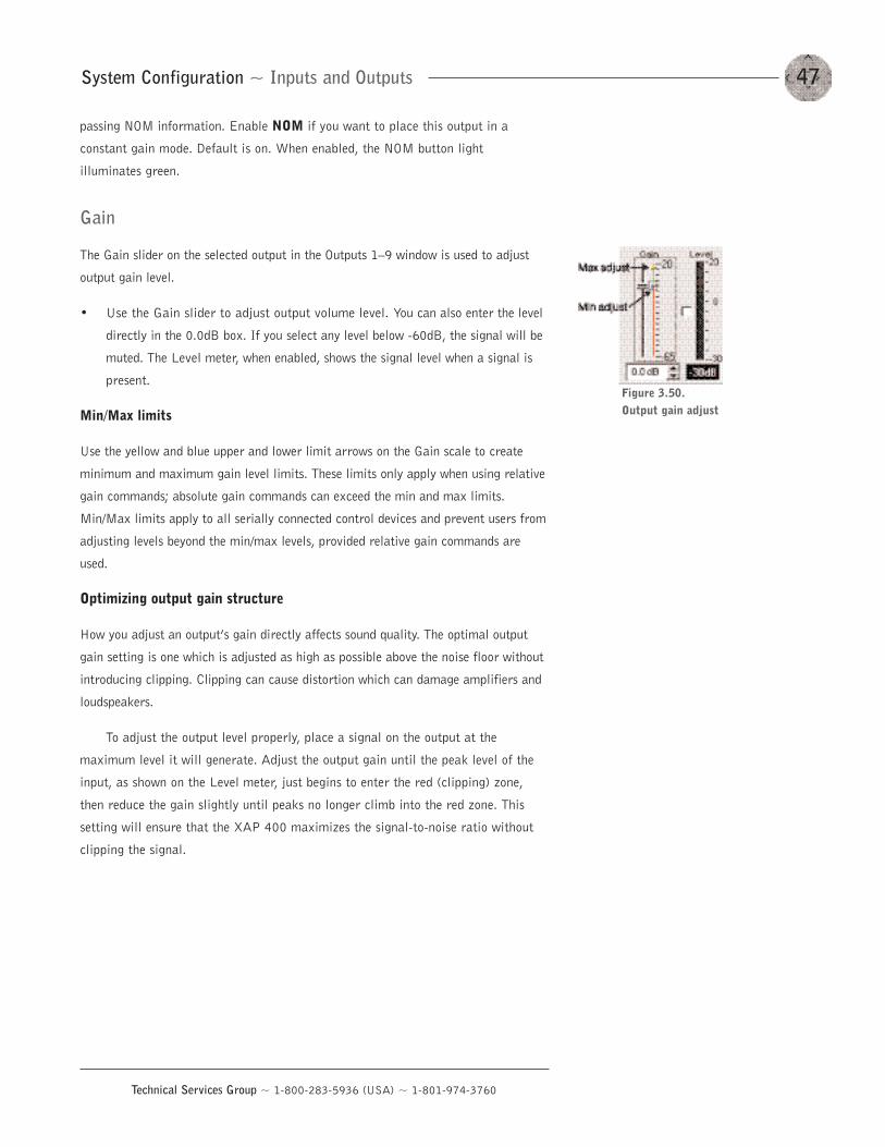
47System Configuration ~ Inputs and Outputs
Technical Services Group ~ 1-800-283-5936 (USA) ~ 1-801-974-3760
passing NOM information. Enable NOM if you want to place this output in a
constant gain mode. Default is on. When enabled, the NOM button light
illuminates green.
Gain
The Gain slider on the selected output in the Outputs 1—9 window is used to adjust
output gain level.
• Use the Gain slider to adjust output volume level. You can also enter the level
directly in the 0.0dB box. If you select any level below -60dB, the signal will be
muted. The Level meter, when enabled, shows the signal level when a signal is
present.
Min/Max limits
Use the yellow and blue upper and lower limit arrows on the Gain scale to create
minimum and maximum gain level limits. These limits only apply when using relative
gain commands; absolute gain commands can exceed the min and max limits.
Min/Max limits apply to all serially connected control devices and prevent users from
adjusting levels beyond the min/max levels, provided relative gain commands are
used.
Optimizing output gain structure
How you adjust an output’s gain directly affects sound quality. The optimal output
gain setting is one which is adjusted as high as possible above the noise floor without
introducing clipping. Clipping can cause distortion which can damage amplifiers and
loudspeakers.
To adjust the output level properly, place a signal on the output at the
maximum level it will generate. Adjust the output gain until the peak level of the
input, as shown on the Level meter, just begins to enter the red (clipping) zone,
then reduce the gain slightly until peaks no longer climb into the red zone. This
setting will ensure that the XAP 400 maximizes the signal-to-noise ratio without
clipping the signal.
Figure 3.50.Output gain adjust
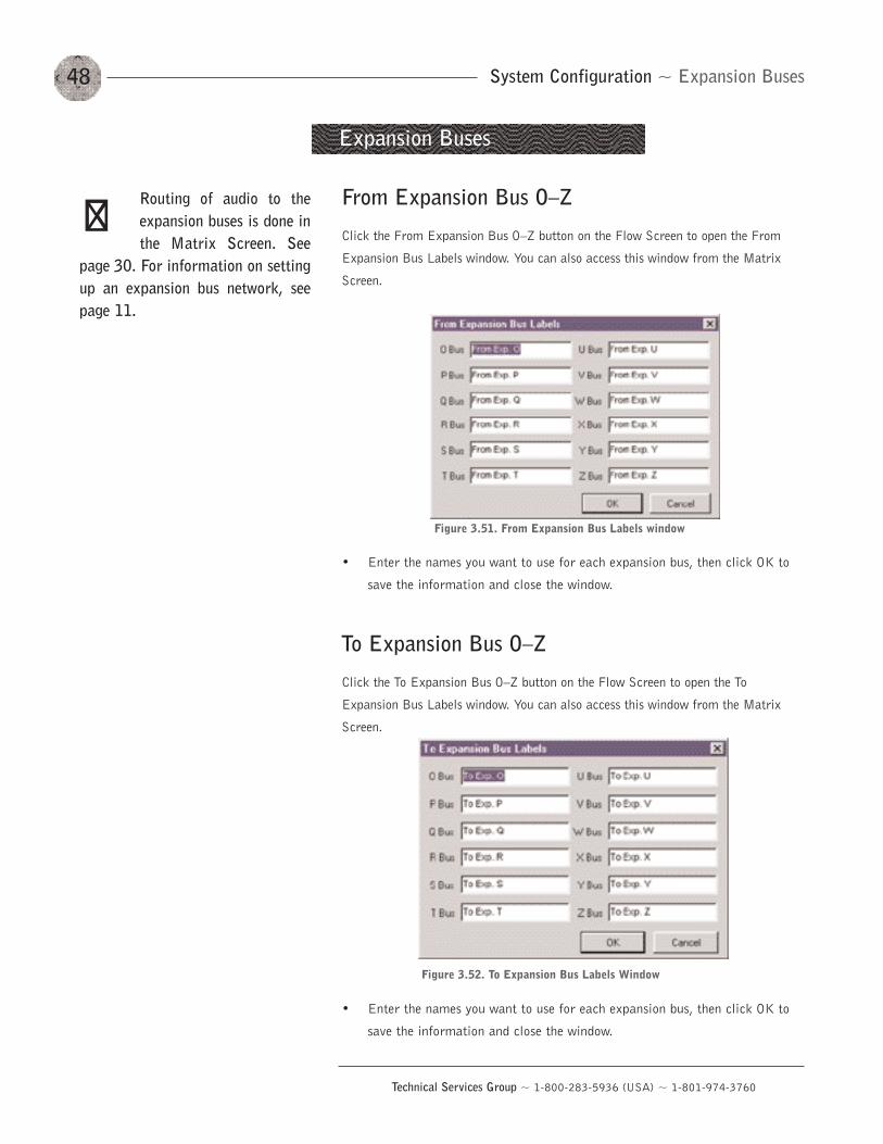
System Configuration ~ Expansion Buses48
Technical Services Group ~ 1-800-283-5936 (USA) ~ 1-801-974-3760
From Expansion Bus O—Z
Click the From Expansion Bus O—Z button on the Flow Screen to open the From
Expansion Bus Labels window. You can also access this window from the Matrix
Screen.
• Enter the names you want to use for each expansion bus, then click OK to
save the information and close the window.
To Expansion Bus O—Z
Click the To Expansion Bus O—Z button on the Flow Screen to open the To
Expansion Bus Labels window. You can also access this window from the Matrix
Screen.
• Enter the names you want to use for each expansion bus, then click OK to
save the information and close the window.
Expansion Buses
Figure 3.51. From Expansion Bus Labels window
Figure 3.52. To Expansion Bus Labels Window
Routing of audio to theexpansion buses is done inthe Matrix Screen. See
page 30. For information on settingup an expansion bus network, seepage 11.
��
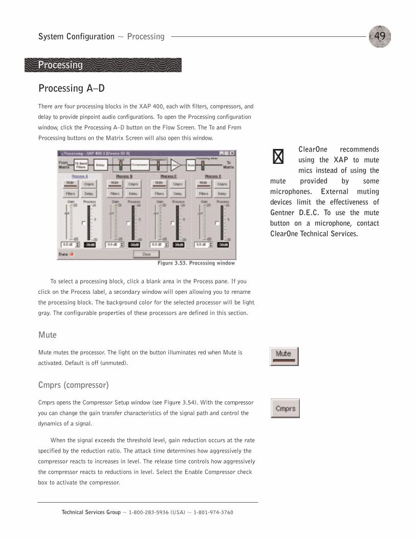
49System Configuration ~ Processing
Technical Services Group ~ 1-800-283-5936 (USA) ~ 1-801-974-3760
Processing A—D
There are four processing blocks in the XAP 400, each with filters, compressors, and
delay to provide pinpoint audio configurations. To open the Processing configuration
window, click the Processing A—D button on the Flow Screen. The To and From
Processing buttons on the Matrix Screen will also open this window.
To select a processing block, click a blank area in the Process pane. If you
click on the Process label, a secondary window will open allowing you to rename
the processing block. The background color for the selected processor will be light
gray. The configurable properties of these processors are defined in this section.
Mute
Mute mutes the processor. The light on the button illuminates red when Mute is
activated. Default is off (unmuted).
Cmprs (compressor)
Cmprs opens the Compressor Setup window (see Figure 3.54). With the compressor
you can change the gain transfer characteristics of the signal path and control the
dynamics of a signal.
When the signal exceeds the threshold level, gain reduction occurs at the rate
specified by the reduction ratio. The attack time determines how aggressively the
compressor reacts to increases in level. The release time controls how aggressively
the compressor reacts to reductions in level. Select the Enable Compressor check
box to activate the compressor.
Processing
Figure 3.53. Processing window
ClearOne recommendsusing the XAP to mutemics instead of using the
mute provided by somemicrophones. External mutingdevices limit the effectiveness ofGentner D.E.C. To use the mutebutton on a microphone, contactClearOne Technical Services.
��
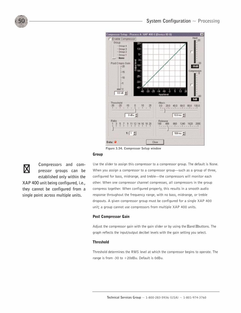
System Configuration ~ Processing50
Technical Services Group ~ 1-800-283-5936 (USA) ~ 1-801-974-3760
Group
Use the slider to assign this compressor to a compressor group. The default is None.
When you assign a compressor to a compressor group–such as a group of three,
configured for bass, midrange, and treble–the compressors will monitor each
other. When one compressor channel compresses, all compressors in the group
compress together. When configured properly, this results in a smooth audio
response throughout the frequency range, with no bass, midrange, or treble
dropouts. A given compressor group must be configured for a single XAP 400
unit; a group cannot use compressors from multiple XAP 400 units.
Post Compressor Gain
Adjust the compressor gain with the gain slider or by using the �and �buttons. The
graph reflects the input/output decibel levels with the gain setting you select.
Threshold
Threshold determines the RMS level at which the compressor begins to operate. The
range is from -30 to +20dBu. Default is 0dBu.
Figure 3.54. Compressor Setup window
Compressors and com-pressor groups can beestablished only within the
XAP 400 unit being configured, i.e.,they cannot be configured from asingle point across multiple units.
��
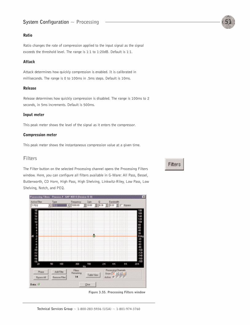
51System Configuration ~ Processing
Technical Services Group ~ 1-800-283-5936 (USA) ~ 1-801-974-3760
Ratio
Ratio changes the rate of compression applied to the input signal as the signal
exceeds the threshold level. The range is 1:1 to 1:20dB. Default is 1:1.
Attack
Attack determines how quickly compression is enabled. It is calibrated in
milliseconds. The range is 0 to 100ms in .5ms steps. Default is 10ms.
Release
Release determines how quickly compression is disabled. The range is 100ms to 2
seconds, in 5ms increments. Default is 500ms.
Input meter
This peak meter shows the level of the signal as it enters the compressor.
Compression meter
This peak meter shows the instantaneous compression value at a given time.
Filters
The Filter button on the selected Processing channel opens the Processing Filters
window. Here, you can configure all filters available in G-Ware: All Pass, Bessel,
Butterworth, CD Horn, High Pass, High Shelving, Linkwitz-Riley, Low Pass, Low
Shelving, Notch, and PEQ.
Figure 3.55. Processing Filters window
The frequency response and phase vs. frequency of the total transfer function
of all filters is displayed in the window. Each filter can be disabled without
affecting the filter settings. All filters can also be disabled using a single
command. By default, they are not enabled and the filter types are not defined. Below
is a description of each feature in the window.
Active Filter
The Active Filter displays the filter that is applied to the processing channel.
Type
Select the filter type from the Type list. Note that the configurable filter
parameters displayed depend on the selected filter type. You can use these
parameters to customize the filter, or use the mouse to click and drag the node on
the graph to a location that reflects the changes you want to make.
You can continue to add filters to the graph, and track their relationships to
each other to design a system with the sound characteristics necessary for good
audio.
Phase
Phase plots the phase response of the frequency response of the selected filter.
Bypass
Bypass All bypasses all filters.
Add Filter
Add Filter adds a filter to the graph.
Remove Filter
This removes the selected filter from the graph.
Table View
Table View toggles between the graph view and the table view. The table view allows
you to configure filters in a table format rather than on the graph, and provides an
easy way to check filter status.
Processing Channels
The Processing Channels section allows you to display the graphs of various
processing channels together, so you can view and easily modify filter and equalizer
settings throughout the frequency range. Click the respective letter to place a
processor in the graph. Click the Active processor you want to modify; it appears in
bold on the graph.
System Configuration ~ Processing52
Technical Services Group ~ 1-800-283-5936 (USA) ~ 1-801-974-3760
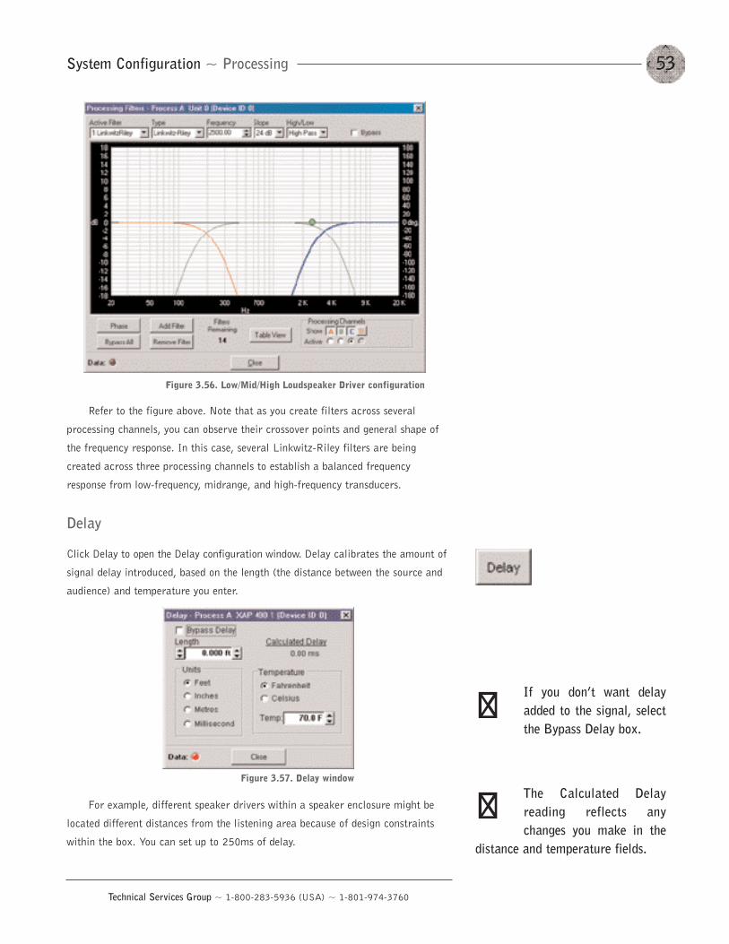
53System Configuration ~ Processing
Technical Services Group ~ 1-800-283-5936 (USA) ~ 1-801-974-3760
Refer to the figure above. Note that as you create filters across several
processing channels, you can observe their crossover points and general shape of
the frequency response. In this case, several Linkwitz-Riley filters are being
created across three processing channels to establish a balanced frequency
response from low-frequency, midrange, and high-frequency transducers.
Delay
Click Delay to open the Delay configuration window. Delay calibrates the amount of
signal delay introduced, based on the length (the distance between the source and
audience) and temperature you enter.
For example, different speaker drivers within a speaker enclosure might be
located different distances from the listening area because of design constraints
within the box. You can set up to 250ms of delay.
Figure 3.56. Low/Mid/High Loudspeaker Driver configuration
Figure 3.57. Delay window
If you don’t want delayadded to the signal, selectthe Bypass Delay box.
The Calculated Delayreading reflects anychanges you make in the
distance and temperature fields.
��
��
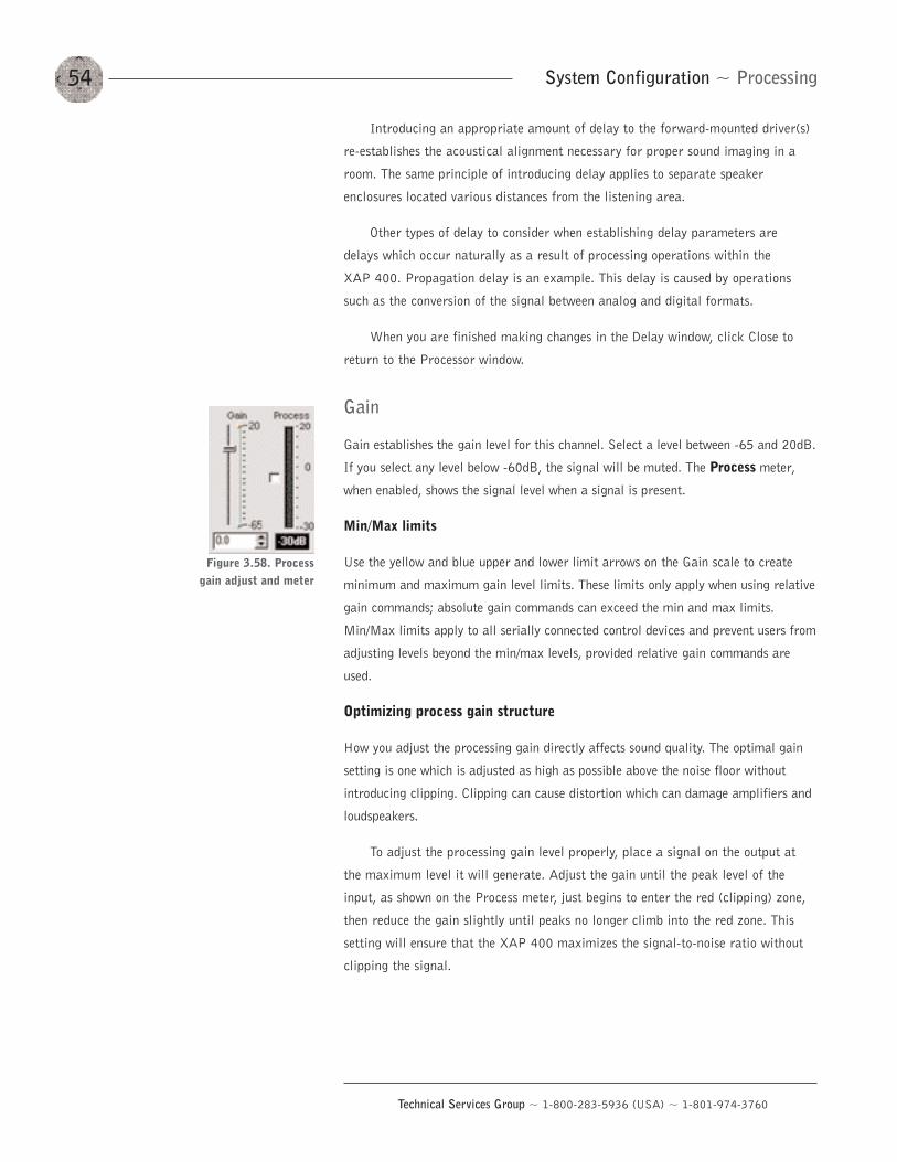
Introducing an appropriate amount of delay to the forward-mounted driver(s)
re-establishes the acoustical alignment necessary for proper sound imaging in a
room. The same principle of introducing delay applies to separate speaker
enclosures located various distances from the listening area.
Other types of delay to consider when establishing delay parameters are
delays which occur naturally as a result of processing operations within the
XAP 400. Propagation delay is an example. This delay is caused by operations
such as the conversion of the signal between analog and digital formats.
When you are finished making changes in the Delay window, click Close to
return to the Processor window.
Gain
Gain establishes the gain level for this channel. Select a level between -65 and 20dB.
If you select any level below -60dB, the signal will be muted. The Process meter,
when enabled, shows the signal level when a signal is present.
Min/Max limits
Use the yellow and blue upper and lower limit arrows on the Gain scale to create
minimum and maximum gain level limits. These limits only apply when using relative
gain commands; absolute gain commands can exceed the min and max limits.
Min/Max limits apply to all serially connected control devices and prevent users from
adjusting levels beyond the min/max levels, provided relative gain commands are
used.
Optimizing process gain structure
How you adjust the processing gain directly affects sound quality. The optimal gain
setting is one which is adjusted as high as possible above the noise floor without
introducing clipping. Clipping can cause distortion which can damage amplifiers and
loudspeakers.
To adjust the processing gain level properly, place a signal on the output at
the maximum level it will generate. Adjust the gain until the peak level of the
input, as shown on the Process meter, just begins to enter the red (clipping) zone,
then reduce the gain slightly until peaks no longer climb into the red zone. This
setting will ensure that the XAP 400 maximizes the signal-to-noise ratio without
clipping the signal.
System Configuration ~ Processing54
Technical Services Group ~ 1-800-283-5936 (USA) ~ 1-801-974-3760
Figure 3.58. Processgain adjust and meter
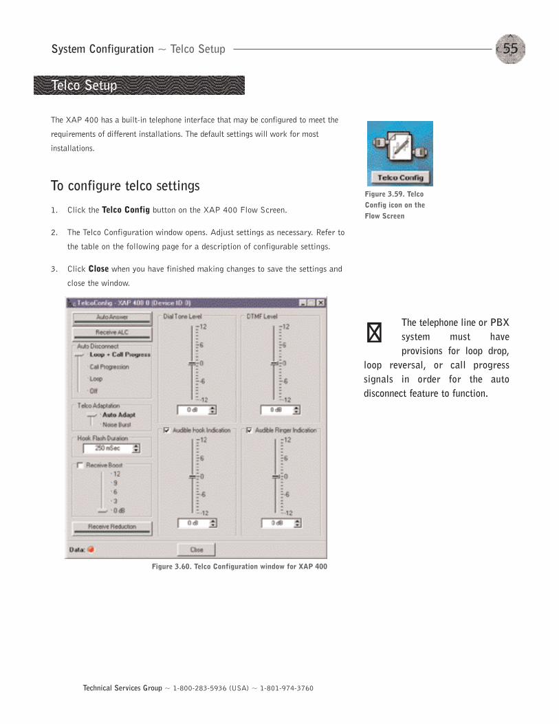
55System Configuration ~ Telco Setup
Technical Services Group ~ 1-800-283-5936 (USA) ~ 1-801-974-3760
The XAP 400 has a built-in telephone interface that may be configured to meet the
requirements of different installations. The default settings will work for most
installations.
To configure telco settings
1. Click the Telco Config button on the XAP 400 Flow Screen.
2. The Telco Configuration window opens. Adjust settings as necessary. Refer to
the table on the following page for a description of configurable settings.
3. Click Close when you have finished making changes to save the settings and
close the window.
Telco Setup
Figure 3.59. TelcoConfig icon on theFlow Screen
Figure 3.60. Telco Configuration window for XAP 400
The telephone line or PBXsystem must haveprovisions for loop drop,
loop reversal, or call progresssignals in order for the autodisconnect feature to function.
��
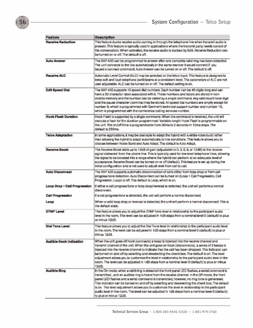
System Configuration ~ Telco Setup56
Technical Services Group ~ 1-800-283-5936 (USA) ~ 1-801-974-3760
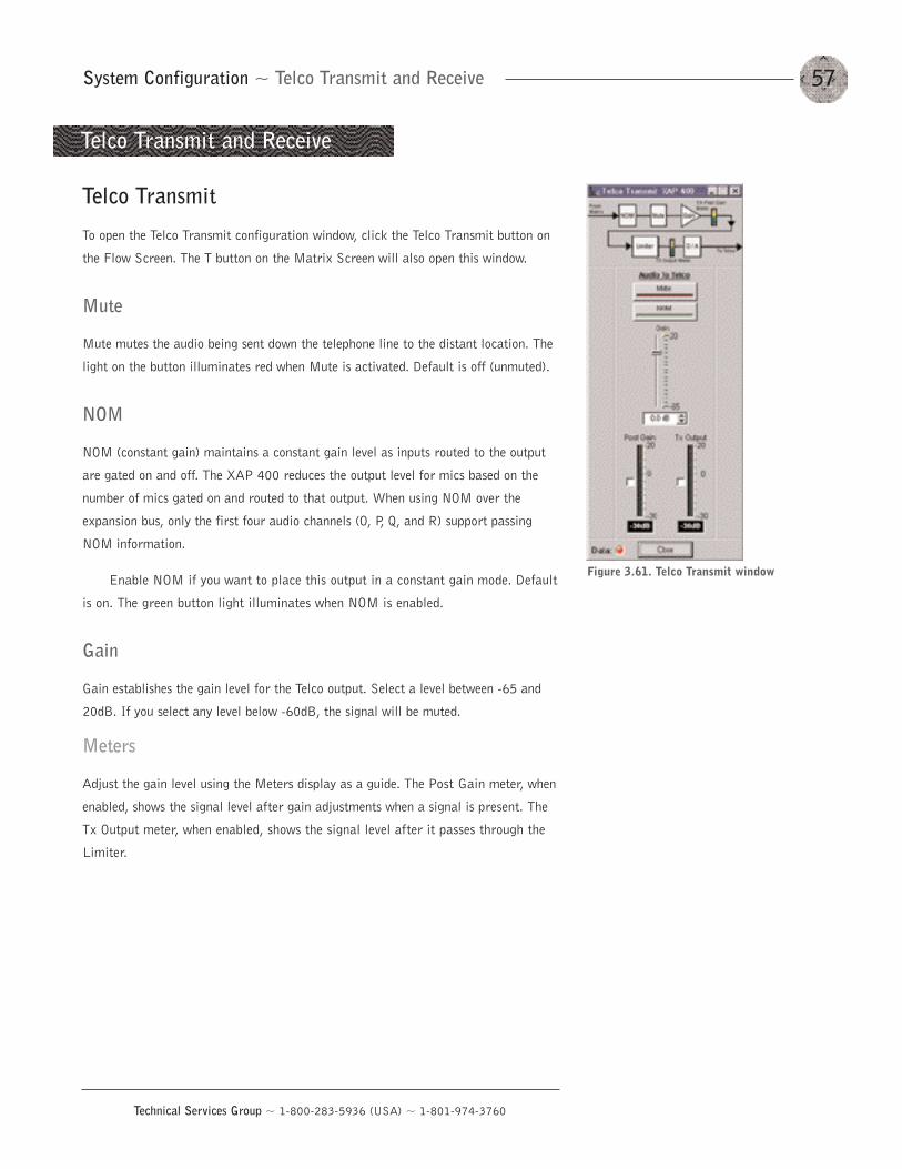
57
Technical Services Group ~ 1-800-283-5936 (USA) ~ 1-801-974-3760
System Configuration ~ Telco Transmit and Receive
Telco Transmit
To open the Telco Transmit configuration window, click the Telco Transmit button on
the Flow Screen. The T button on the Matrix Screen will also open this window.
Mute
Mute mutes the audio being sent down the telephone line to the distant location. The
light on the button illuminates red when Mute is activated. Default is off (unmuted).
NOM
NOM (constant gain) maintains a constant gain level as inputs routed to the output
are gated on and off. The XAP 400 reduces the output level for mics based on the
number of mics gated on and routed to that output. When using NOM over the
expansion bus, only the first four audio channels (O, P, Q, and R) support passing
NOM information.
Enable NOM if you want to place this output in a constant gain mode. Default
is on. The green button light illuminates when NOM is enabled.
Gain
Gain establishes the gain level for the Telco output. Select a level between -65 and
20dB. If you select any level below -60dB, the signal will be muted.
Meters
Adjust the gain level using the Meters display as a guide. The Post Gain meter, when
enabled, shows the signal level after gain adjustments when a signal is present. The
Tx Output meter, when enabled, shows the signal level after it passes through the
Limiter.
Telco Transmit and Receive
Figure 3.61. Telco Transmit window
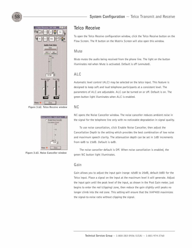
System Configuration ~ Telco Transmit and Receive58
Technical Services Group ~ 1-800-283-5936 (USA) ~ 1-801-974-3760
Telco Receive
To open the Telco Receive configuration window, click the Telco Receive button on the
Flow Screen. The R button on the Matrix Screen will also open this window.
Mute
Mute mutes the audio being received from the phone line. The light on the button
illuminates red when Mute is activated. Default is off (unmuted).
ALC
Automatic level control (ALC) may be selected on the telco input. This feature is
designed to keep soft and loud telephone participants at a consistent level. The
parameters of ALC are adjustable. ALC can be turned on or off. Default is on. The
green button light illuminates when ALC is enabled.
NC
NC opens the Noise Canceller window. The noise canceller reduces ambient noise in
the signal for the telephone line only with no noticeable degradation in signal quality.
To use noise cancellation, click Enable Noise Canceller, then adjust the
Cancellation Depth to the setting which provides the best combination of low noise
and maximum speech clarity. The attenuation depth can be set in 1dB increments
from 6dB to 15dB. Default is 6dB.
The noise canceller default is Off. When noise cancellation is enabled, the
green NC button light illuminates.
Gain
Gain allows you to adjust the input gain (range -65dB to 20dB, default 0dB) for the
Telco input. Place a signal on the input at the maximum level it will generate. Adjust
the input gain until the peak level of the input, as shown in the Post Gain meter, just
begins to enter the red (clipping) zone, then reduce the gain slightly until peaks no
longer climb into the red zone. This setting will ensure that the XAP400 maximizes
the signal-to-noise ratio without clipping the signal.
Figure 3.62. Telco Receive window
Figure 3.63. Noise Canceller window
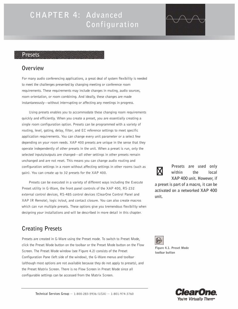
Technical Services Group ~ 1-800-283-5936 (USA) ~ 1-801-974-3760
CHAPTER 4: AdvancedConfiguration
Presets
Overview
For many audio conferencing applications, a great deal of system flexibility is needed
to meet the challenges presented by changing meeting or conference room
requirements. These requirements may include changes in muting, audio sources,
room orientation, or room combining. And ideally, these changes are made
instantaneously–without interrupting or affecting any meetings in progress.
Using presets enables you to accommodate these changing room requirements
quickly and efficiently. When you create a preset, you are essentially creating a
single room configuration option. Presets can be programmed with a variety of
routing, level, gating, delay, filter, and EC reference settings to meet specific
application requirements. You can change every unit parameter or a select few
depending on your room needs. XAP 400 presets are unique in the sense that they
operate independently of other presets in the unit. When a preset is run, only the
selected inputs/outputs are changed–all other settings in other presets remain
unchanged and are not reset. This means you can change audio routing and
configuration settings in a room without affecting settings in other rooms (such as
gain). You can create up to 32 presets for the XAP 400.
Presets can be executed in a variety of different ways including the Execute
Preset utility in G-Ware, the front panel controls of the XAP 400, RS-232
external control devices, RS-485 control devices (ClearOne Control Panel and
XAP IR Remote), logic in/out, and contact closure. You can also create macros
which can run multiple presets. These options give you tremendous flexibility when
designing your installations and will be described in more detail in this chapter.
Creating Presets
Presets are created in G-Ware using the Preset mode. To switch to Preset Mode,
click the Preset Mode button on the toolbar or the Preset Mode button on the Flow
Screen. The Preset Mode window (see Figure 4.2) consists of the Preset
Configuration Pane (left side of the window), the G-Ware menus and toolbar
(although most options are not available because they do not apply to presets), and
the Preset Matrix Screen. There is no Flow Screen in Preset Mode since all
configurable settings can be accessed from the Matrix Screen.
Figure 4.1. Preset Modetoolbar button
Presets are used onlywithin the local XAP 400 unit. However, if
a preset is part of a macro, it can beactivated on a networked XAP 400unit.
��
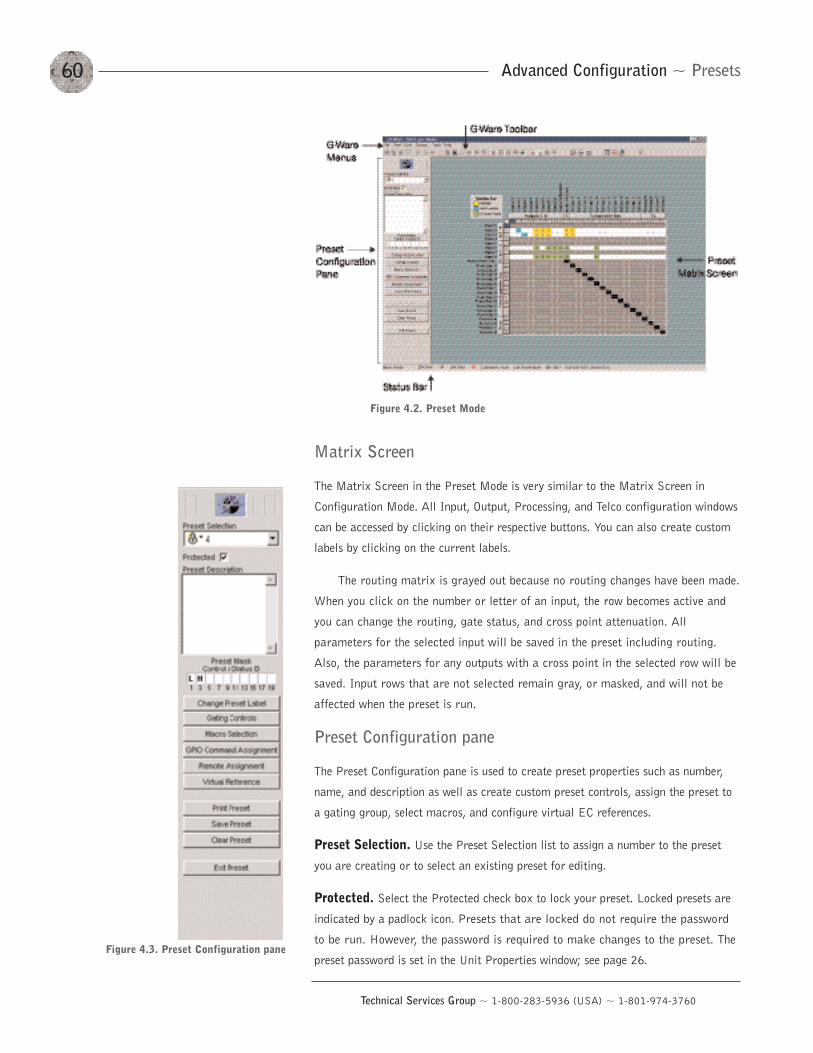
Advanced Configuration ~ Presets60
Technical Services Group ~ 1-800-283-5936 (USA) ~ 1-801-974-3760
Figure 4.3. Preset Configuration pane
Matrix Screen
The Matrix Screen in the Preset Mode is very similar to the Matrix Screen in
Configuration Mode. All Input, Output, Processing, and Telco configuration windows
can be accessed by clicking on their respective buttons. You can also create custom
labels by clicking on the current labels.
The routing matrix is grayed out because no routing changes have been made.
When you click on the number or letter of an input, the row becomes active and
you can change the routing, gate status, and cross point attenuation. All
parameters for the selected input will be saved in the preset including routing.
Also, the parameters for any outputs with a cross point in the selected row will be
saved. Input rows that are not selected remain gray, or masked, and will not be
affected when the preset is run.
Preset Configuration pane
The Preset Configuration pane is used to create preset properties such as number,
name, and description as well as create custom preset controls, assign the preset to
a gating group, select macros, and configure virtual EC references.
Preset Selection. Use the Preset Selection list to assign a number to the preset
you are creating or to select an existing preset for editing.
Protected. Select the Protected check box to lock your preset. Locked presets are
indicated by a padlock icon. Presets that are locked do not require the password
to be run. However, the password is required to make changes to the preset. The
preset password is set in the Unit Properties window; see page 26.
Figure 4.2. Preset Mode
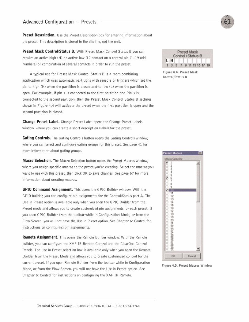
61Advanced Configuration ~ Presets
Technical Services Group ~ 1-800-283-5936 (USA) ~ 1-801-974-3760
Figure 4.5. Preset Macros Window
Preset Description. Use the Preset Description box for entering information about
the preset. This description is stored in the site file, not the unit.
Preset Mask Control/Status B. With Preset Mask Control Status B you can
require an active high (H) or active low (L) contact on a control pin (1—19 odd
numbers) or combination of several contacts in order to run the preset.
A typical use for Preset Mask Control Status B is a room combining
application which uses automatic partitions with sensors or triggers which set the
pin to high (H) when the partition is closed and to low (L) when the partition is
open. For example, if pin 1 is connected to the first partition and Pin 3 is
connected to the second partition, then the Preset Mask Control Status B settings
shown in Figure 4.4 will activate the preset when the first partition is open and the
second partition is closed.
Change Preset Label. Change Preset Label opens the Change Preset Labels
window, where you can create a short description (label) for the preset.
Gating Controls. The Gating Controls button opens the Gating Controls window,
where you can select and configure gating groups for this preset. See page 41 for
more information about gating groups.
Macro Selection. The Macro Selection button opens the Preset Macros window,
where you assign specific macros to the preset you’re creating. Select the macros you
want to use with this preset, then click OK to save changes. See page 67 for more
information about creating macros.
GPIO Command Assignment. This opens the GPIO Builder window. With the
GPIO builder, you can configure pin assignments for the Control/Status port A. The
Use in Preset option is available only when you open the GPIO Builder from the
Preset mode and allows you to create customized pin assignments for each preset. If
you open GPIO Builder from the toolbar while in Configuration Mode, or from the
Flow Screen, you will not have the Use in Preset option. See Chapter 6: Control for
instructions on configuring pin assignments.
Remote Assignment. This opens the Remote Builder window. With the Remote
builder, you can configure the XAP IR Remote Control and the ClearOne Control
Panels. The Use in Preset selection box is available only when you open the Remote
Builder from the Preset Mode and allows you to create customized control for the
current preset. If you open Remote Builder from the toolbar while in Configuration
Mode, or from the Flow Screen, you will not have the Use in Preset option. See
Chapter 6: Control for instructions on configuring the XAP IR Remote.
Figure 4.4. Preset MaskControl/Status B
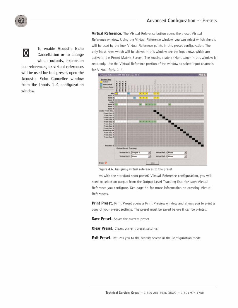
Advanced Configuration ~ Presets62
Technical Services Group ~ 1-800-283-5936 (USA) ~ 1-801-974-3760
Virtual Reference. The Virtual Reference button opens the preset Virtual
Reference window. Using the Virtual Reference window, you can select which signals
will be used by the four Virtual Reference points in this preset configuration. The
only input rows which will be shown in this window are the input rows which are
active in the Preset Matrix Screen. The routing matrix (right pane) in this window is
read-only. Use the Virtual Reference portion of the window to select input channels
for Virtual Refs. 1—4.
As with the standard (non-preset) Virtual Reference configuration, you will
need to select an output from the Output Level Tracking lists for each Virtual
Reference you configure. See page 34 for more information on creating Virtual
References.
Print Preset. Print Preset opens a Print Preview window and allows you to print a
copy of your preset settings. The preset must be saved before it can be printed.
Save Preset. Saves the current preset.
Clear Preset. Clears current preset settings.
Exit Preset. Returns you to the Matrix screen in the Configuration mode.
Figure 4.6. Assigning virtual references to the preset
To enable Acoustic EchoCancellation or to changewhich outputs, expansion
bus references, or virtual referenceswill be used for this preset, open theAcoustic Echo Canceller windowfrom the Inputs 1—4 configurationwindow.
��
63Advanced Configuration ~ Presets
Technical Services Group ~ 1-800-283-5936 (USA) ~ 1-801-974-3760
To create a preset
1. From the Preset Selection list, select the number of the preset you will be
configuring. Enter a description of the preset in the Preset Description box.
2. If you want to password protect this preset, click Protected. See page 26
for information on creating the preset password.
3. Configure the routing matrix and make cross point attenuation adjustments.
4. Configure input, output, processing, and telco channel settings as needed.
See Chapter 3: System Configuration for specific instructions on unit
settings.
5. Click Gating Controls to set up gating parameters for the preset.
6. Make GPIO or Remote assignments as needed.
7. Click Virtual Reference if you need to create Virtual References specific to
the preset.
8. When you have finished configuring the preset, click Save Preset to save
the settings. Click Exit Preset to exit Preset Mode.
Storage space
In a realistic preset configuration scenario, it is highly unlikely that you would reach
the storage capacity of the unit. In the event that you exceed the preset storage
space, G-Ware will alert you when you try to save the preset. You will be asked to
reduce the number of cross point changes or the number of macros in the preset. As
a general rule, if you make cross point changes to three-fourths of the matrix, you
can establish a maximum of 128 nested macros for a given preset.
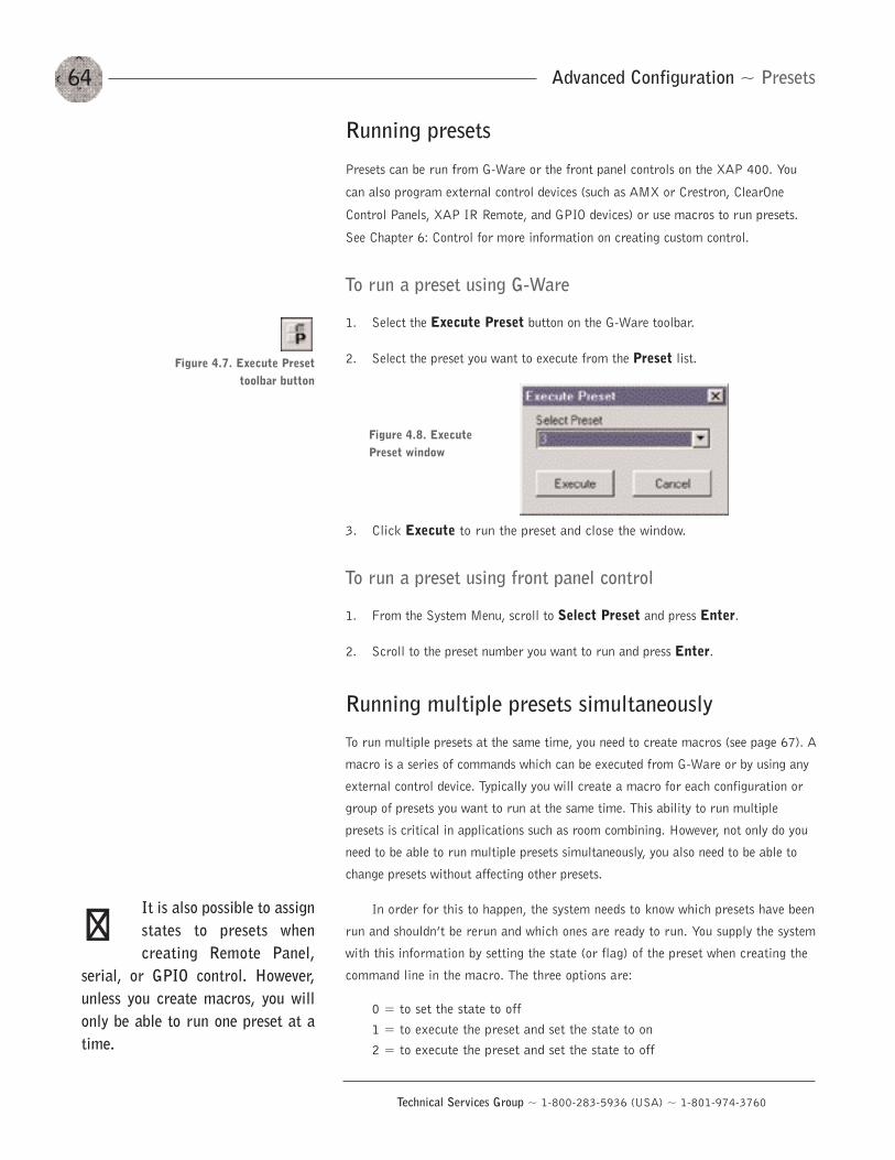
Advanced Configuration ~ Presets64
Technical Services Group ~ 1-800-283-5936 (USA) ~ 1-801-974-3760
Running presets
Presets can be run from G-Ware or the front panel controls on the XAP 400. You
can also program external control devices (such as AMX or Crestron, ClearOne
Control Panels, XAP IR Remote, and GPIO devices) or use macros to run presets.
See Chapter 6: Control for more information on creating custom control.
To run a preset using G-Ware
1. Select the Execute Preset button on the G-Ware toolbar.
2. Select the preset you want to execute from the Preset list.
3. Click Execute to run the preset and close the window.
To run a preset using front panel control
1. From the System Menu, scroll to Select Preset and press Enter.
2. Scroll to the preset number you want to run and press Enter.
Running multiple presets simultaneously
To run multiple presets at the same time, you need to create macros (see page 67). A
macro is a series of commands which can be executed from G-Ware or by using any
external control device. Typically you will create a macro for each configuration or
group of presets you want to run at the same time. This ability to run multiple
presets is critical in applications such as room combining. However, not only do you
need to be able to run multiple presets simultaneously, you also need to be able to
change presets without affecting other presets.
In order for this to happen, the system needs to know which presets have been
run and shouldn’t be rerun and which ones are ready to run. You supply the system
with this information by setting the state (or flag) of the preset when creating the
command line in the macro. The three options are:
0 = to set the state to off1 = to execute the preset and set the state to on2 = to execute the preset and set the state to off
Figure 4.8. ExecutePreset window
Figure 4.7. Execute Presettoolbar button
It is also possible to assignstates to presets whencreating Remote Panel,
serial, or GPIO control. However,unless you create macros, you willonly be able to run one preset at atime.
��
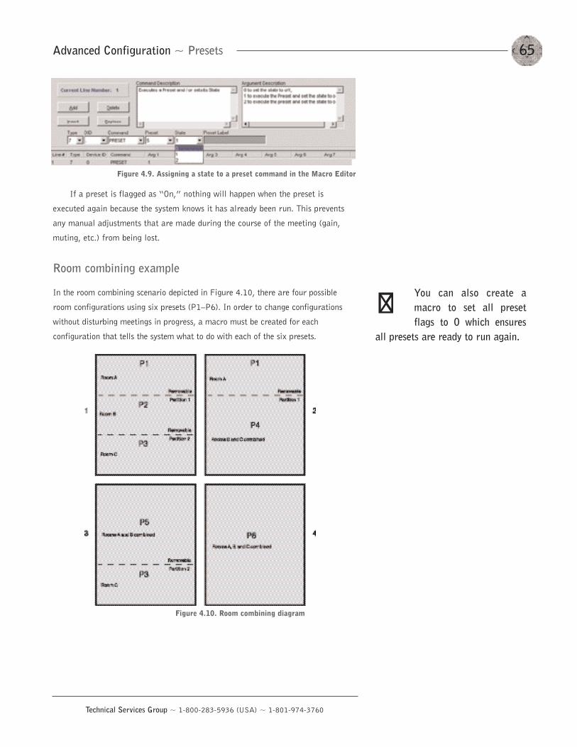
65Advanced Configuration ~ Presets
Technical Services Group ~ 1-800-283-5936 (USA) ~ 1-801-974-3760
If a preset is flagged as “On,” nothing will happen when the preset is
executed again because the system knows it has already been run. This prevents
any manual adjustments that are made during the course of the meeting (gain,
muting, etc.) from being lost.
Room combining example
In the room combining scenario depicted in Figure 4.10, there are four possible
room configurations using six presets (P1—P6). In order to change configurations
without disturbing meetings in progress, a macro must be created for each
configuration that tells the system what to do with each of the six presets.
Figure 4.9. Assigning a state to a preset command in the Macro Editor
You can also create amacro to set all presetflags to 0 which ensures
all presets are ready to run again.
��
Figure 4.10. Room combining diagram
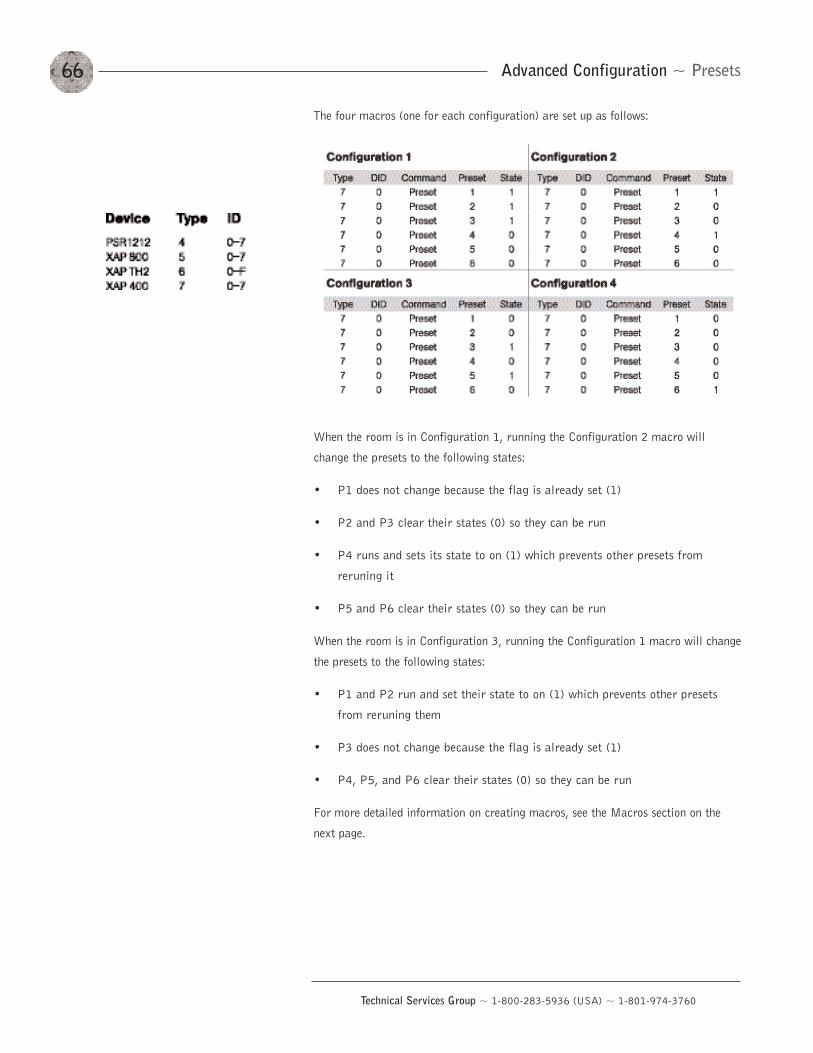
Advanced Configuration ~ Presets66
Technical Services Group ~ 1-800-283-5936 (USA) ~ 1-801-974-3760
The four macros (one for each configuration) are set up as follows:
When the room is in Configuration 1, running the Configuration 2 macro will
change the presets to the following states:
• P1 does not change because the flag is already set (1)
• P2 and P3 clear their states (0) so they can be run
• P4 runs and sets its state to on (1) which prevents other presets from
reruning it
• P5 and P6 clear their states (0) so they can be run
When the room is in Configuration 3, running the Configuration 1 macro will change
the presets to the following states:
• P1 and P2 run and set their state to on (1) which prevents other presets
from reruning them
• P3 does not change because the flag is already set (1)
• P4, P5, and P6 clear their states (0) so they can be run
For more detailed information on creating macros, see the Macros section on the
next page.
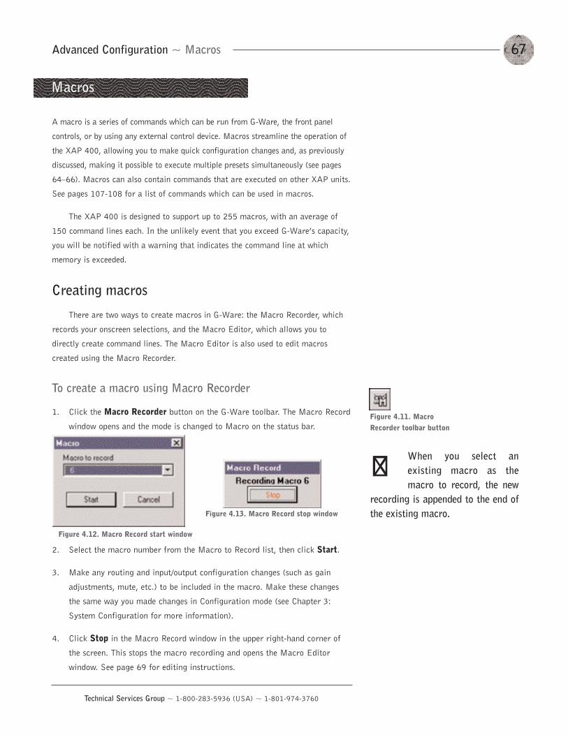
67Advanced Configuration ~ Macros
Technical Services Group ~ 1-800-283-5936 (USA) ~ 1-801-974-3760
A macro is a series of commands which can be run from G-Ware, the front panel
controls, or by using any external control device. Macros streamline the operation of
the XAP 400, allowing you to make quick configuration changes and, as previously
discussed, making it possible to execute multiple presets simultaneously (see pages
64—66). Macros can also contain commands that are executed on other XAP units.
See pages 107-108 for a list of commands which can be used in macros.
The XAP 400 is designed to support up to 255 macros, with an average of
150 command lines each. In the unlikely event that you exceed G-Ware’s capacity,
you will be notified with a warning that indicates the command line at which
memory is exceeded.
Creating macros
There are two ways to create macros in G-Ware: the Macro Recorder, which
records your onscreen selections, and the Macro Editor, which allows you to
directly create command lines. The Macro Editor is also used to edit macros
created using the Macro Recorder.
To create a macro using Macro Recorder
1. Click the Macro Recorder button on the G-Ware toolbar. The Macro Record
window opens and the mode is changed to Macro on the status bar.
2. Select the macro number from the Macro to Record list, then click Start.
3. Make any routing and input/output configuration changes (such as gain
adjustments, mute, etc.) to be included in the macro. Make these changes
the same way you made changes in Configuration mode (see Chapter 3:
System Configuration for more information).
4. Click Stop in the Macro Record window in the upper right-hand corner of
the screen. This stops the macro recording and opens the Macro Editor
window. See page 69 for editing instructions.
Macros
Figure 4.12. Macro Record start window
Figure 4.13. Macro Record stop window
Figure 4.11. MacroRecorder toolbar button
When you select anexisting macro as themacro to record, the new
recording is appended to the end ofthe existing macro.
��
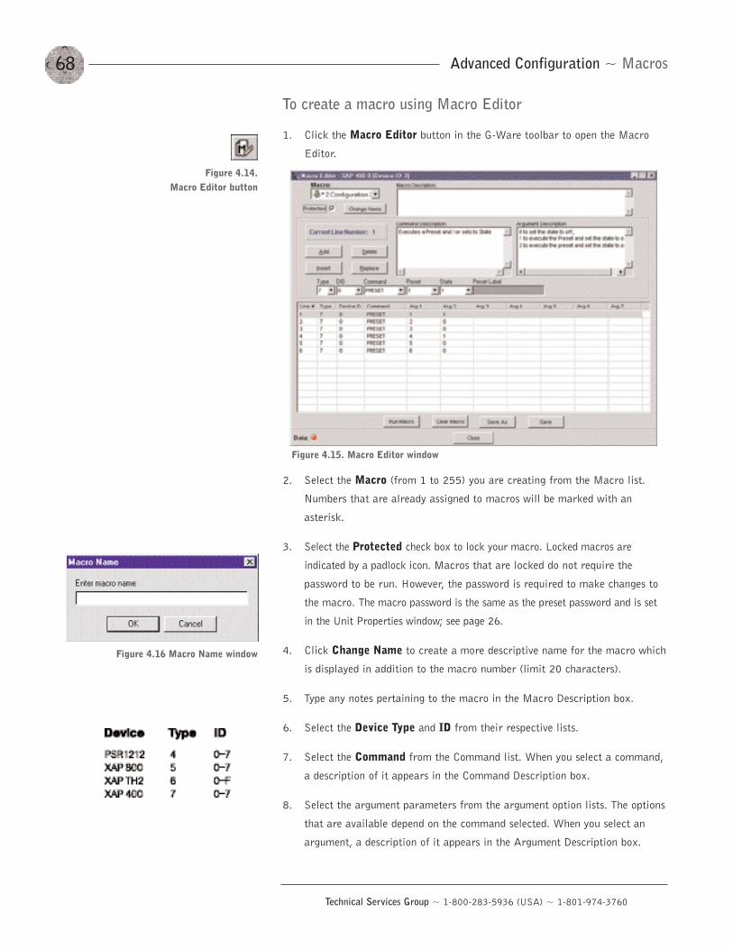
Advanced Configuration ~ Macros68
Technical Services Group ~ 1-800-283-5936 (USA) ~ 1-801-974-3760
To create a macro using Macro Editor
1. Click the Macro Editor button in the G-Ware toolbar to open the Macro
Editor.
2. Select the Macro (from 1 to 255) you are creating from the Macro list.
Numbers that are already assigned to macros will be marked with an
asterisk.
3. Select the Protected check box to lock your macro. Locked macros are
indicated by a padlock icon. Macros that are locked do not require the
password to be run. However, the password is required to make changes to
the macro. The macro password is the same as the preset password and is set
in the Unit Properties window; see page 26.
4. Click Change Name to create a more descriptive name for the macro which
is displayed in addition to the macro number (limit 20 characters).
5. Type any notes pertaining to the macro in the Macro Description box.
6. Select the Device Type and ID from their respective lists.
7. Select the Command from the Command list. When you select a command,
a description of it appears in the Command Description box.
8. Select the argument parameters from the argument option lists. The options
that are available depend on the command selected. When you select an
argument, a description of it appears in the Argument Description box.
Figure 4.15. Macro Editor window
Figure 4.16 Macro Name window
Figure 4.14. Macro Editor button
69Advanced Configuration ~ Macros
Technical Services Group ~ 1-800-283-5936 (USA) ~ 1-801-974-3760
9. Click Add to place the command into the macro. The command line now
appears in the command line table.
You can now create another command line for the macro or save the
completed macro.
Editing macros
With the Macro Editor, you can add, edit, or remove command lines in the macro. If
you used the Macro Recorder to create a macro, the Macro Editor opens
automatically. Otherwise, click the Macro Editor toolbar button.
To edit a macro
1. Select the macro from the Macro list.
2. Click Change Name to edit the macro label.
3. Double-click the command line you want to edit. The Current Line Number
displays the selected command line.
4. Make changes to the command or arguments by selecting options from the
drop-down lists.
5. Click Replace to overwrite the old command line with the new changes.
6. Click Save or Save As to save the macro.
To delete a macro
• Click Clear Macro to delete the entire macro.
• Click Delete to delete the selected command line.
To add or insert a command line
• Click Add to place the current command line into the next available row in
the command line table.
• Click Insert to insert the current command line into the row directly above
the currently selected command line in the table.
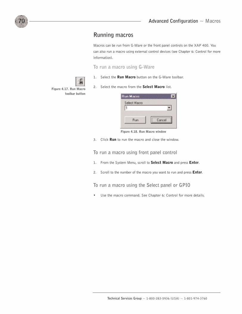
Advanced Configuration ~ Macros70
Technical Services Group ~ 1-800-283-5936 (USA) ~ 1-801-974-3760
Running macros
Macros can be run from G-Ware or the front panel controls on the XAP 400. You
can also run a macro using external control devices (see Chapter 6: Control for more
information).
To run a macro using G-Ware
1. Select the Run Macro button on the G-Ware toolbar.
2. Select the macro from the Select Macro list.
3. Click Run to run the macro and close the window.
To run a macro using front panel control
1. From the System Menu, scroll to Select Macro and press Enter.
2. Scroll to the number of the macro you want to run and press Enter.
To run a macro using the Select panel or GPIO
• Use the macro command. See Chapter 6: Control for more details.
Figure 4.18. Run Macro window
Figure 4.17. Run Macrotoolbar button
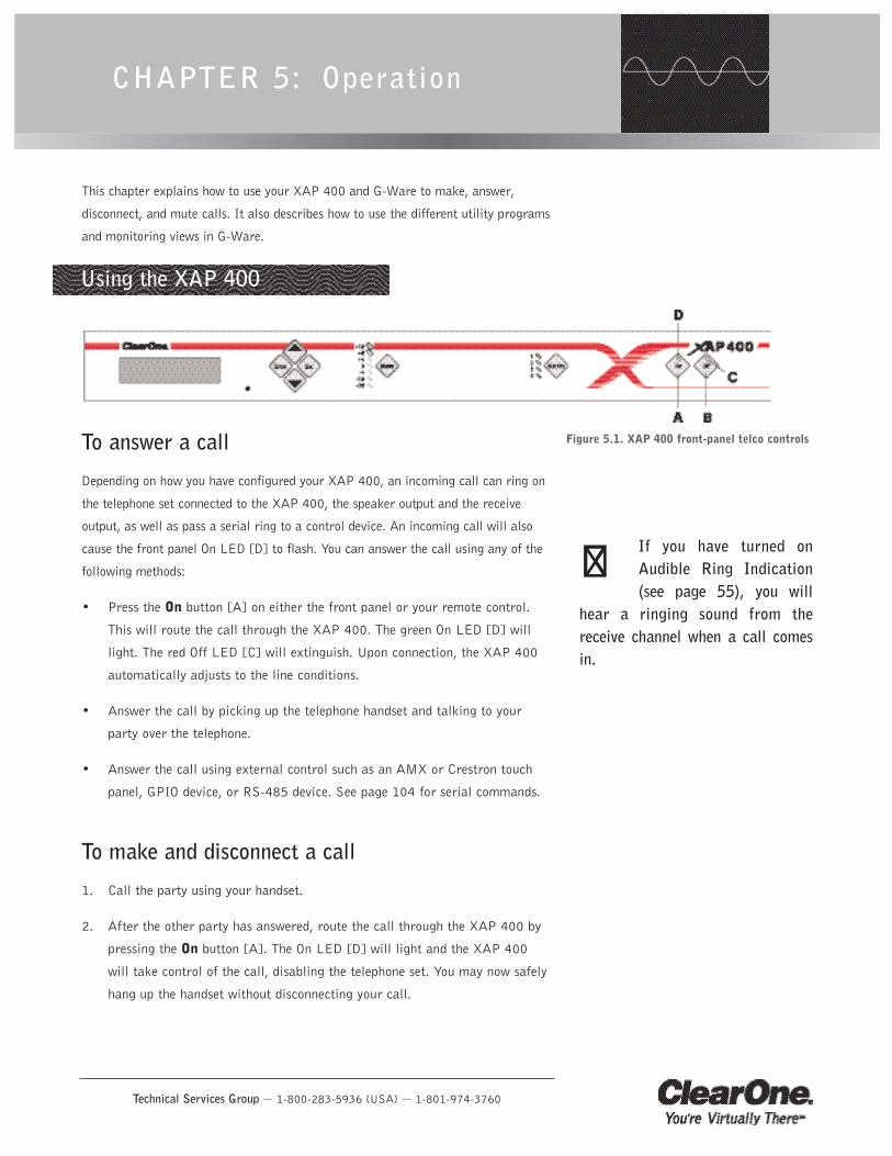
Technical Services Group ~ 1-800-283-5936 (USA) ~ 1-801-974-3760
This chapter explains how to use your XAP 400 and G-Ware to make, answer,
disconnect, and mute calls. It also describes how to use the different utility programs
and monitoring views in G-Ware.
To answer a call
Depending on how you have configured your XAP 400, an incoming call can ring on
the telephone set connected to the XAP 400, the speaker output and the receive
output, as well as pass a serial ring to a control device. An incoming call will also
cause the front panel On LED [D] to flash. You can answer the call using any of the
following methods:
• Press the On button [A] on either the front panel or your remote control.
This will route the call through the XAP 400. The green On LED [D] will
light. The red Off LED [C] will extinguish. Upon connection, the XAP 400
automatically adjusts to the line conditions.
• Answer the call by picking up the telephone handset and talking to your
party over the telephone.
• Answer the call using external control such as an AMX or Crestron touch
panel, GPIO device, or RS-485 device. See page 104 for serial commands.
To make and disconnect a call
1. Call the party using your handset.
2. After the other party has answered, route the call through the XAP 400 by
pressing the On button [A]. The On LED [D] will light and the XAP 400
will take control of the call, disabling the telephone set. You may now safely
hang up the handset without disconnecting your call.
CHAPTER 5: Operation
Using the XAP 400
Figure 5.1. XAP 400 front-panel telco controls
If you have turned onAudible Ring Indication(see page 55), you will
hear a ringing sound from thereceive channel when a call comesin.
��
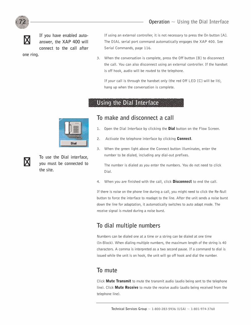
Operation ~ Using the Dial Interface72
Technical Services Group ~ 1-800-283-5936 (USA) ~ 1-801-974-3760
If using an external controller, it is not necessary to press the On button [A].
The DIAL serial port command automatically engages the XAP 400. See
Serial Commands, page 116.
3. When the conversation is complete, press the Off button [B] to disconnect
the call. You can also disconnect using an external controller. If the handset
is off hook, audio will be routed to the telephone.
If your call is through the handset only (the red Off LED [C] will be lit),
hang up when the conversation is complete.
To make and disconnect a call
1. Open the Dial Interface by clicking the Dial button on the Flow Screen.
2. Activate the telephone interface by clicking Connect.
3. When the green light above the Connect button illuminates, enter the
number to be dialed, including any dial-out prefixes.
The number is dialed as you enter the numbers. You do not need to click
Dial.
4. When you are finished with the call, click Disconnect to end the call.
If there is noise on the phone line during a call, you might need to click the Re-Null
button to force the interface to readapt to the line. After the unit sends a noise burst
down the line for adaptation, it automatically switches to auto adapt mode. The
receive signal is muted during a noise burst.
To dial multiple numbers
Numbers can be dialed one at a time or a string can be dialed at one time
(In-Block). When dialing multiple numbers, the maximum length of the string is 40
characters. A comma is interpreted as a two second pause. If a command to dial is
issued while the unit is on hook, the unit will go off hook and dial the number.
To mute
Click Mute Transmit to mute the transmit audio (audio being sent to the telephone
line). Click Mute Receive to mute the receive audio (audio being received from the
telephone line).
If you have enabled auto-answer, the XAP 400 willconnect to the call after
one ring.
��
Using the Dial Interface
To use the Dial interface,you must be connected tothe site.
��
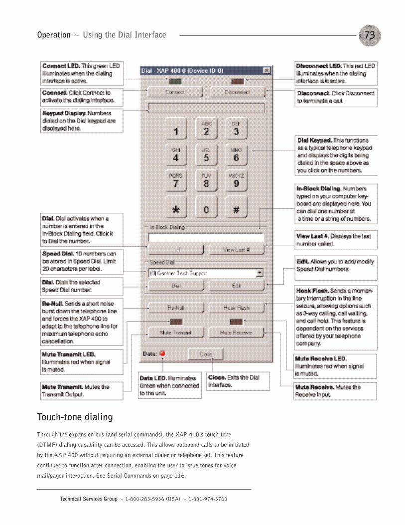
73
Technical Services Group ~ 1-800-283-5936 (USA) ~ 1-801-974-3760
Touch-tone dialing
Through the expansion bus (and serial commands), the XAP 400’s touch-tone
(DTMF) dialing capability can be accessed. This allows outbound calls to be initiated
by the XAP 400 without requiring an external dialer or telephone set. This feature
continues to function after connection, enabling the user to issue tones for voice
mail/pager interaction. See Serial Commands on page 116.
Operation ~ Using the Dial Interface
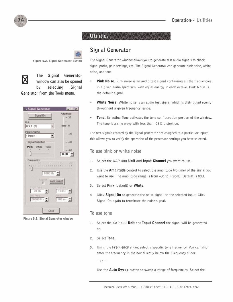
Operation~ Utilities74
Technical Services Group ~ 1-800-283-5936 (USA) ~ 1-801-974-3760
Signal Generator
The Signal Generator window allows you to generate test audio signals to check
signal paths, gain settings, etc. The Signal Generator can generate pink noise, white
noise, and tone.
• Pink Noise. Pink noise is an audio test signal containing all the frequencies
in a given audio spectrum, with equal energy in each octave. Pink Noise is
the default signal.
• White Noise. White noise is an audio test signal which is distributed evenly
throughout a given frequency range.
• Tone. Selecting Tone activates the tone configuration portion of the window.
The tone is a sine wave with less than .03% distortion.
The test signals created by the signal generator are assigned to a particular input;
this allows you to verify the operation of the processor settings you have selected.
To use pink or white noise
1. Select the XAP 400 Unit and Input Channel you want to use.
2. Use the Amplitude control to select the amplitude (volume) of the signal you
want to use. The amplitude range is from -60 to +20dB. Default is 0dB.
3. Select Pink (default) or White.
4 Click Signal On to generate the noise signal on the selected input. Click
Signal On again to terminate the noise signal.
To use tone
1. Select the XAP 400 Unit and Input Channel the signal will be generated
on.
2. Select Tone.
3. Using the Frequency slider, select a specific tone frequency. You can also
enter the frequency in the box directly below the Frequency slider.
— or —
Use the Auto Sweep button to sweep a range of frequencies. Select the
Utilities
Figure 5.2. Signal Generator Button
The Signal Generatorwindow can also be openedby selecting Signal
Generator from the Tools menu.
��
Figure 5.3. Signal Generator window
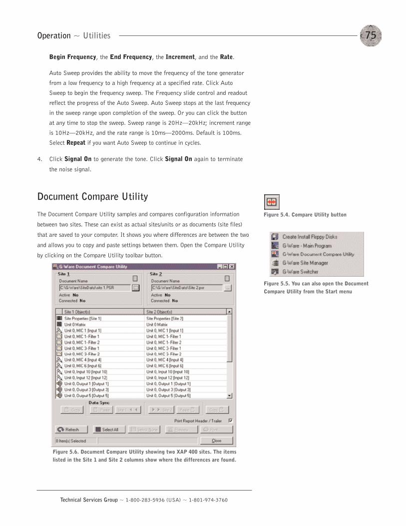
75Operation ~ Utilities
Technical Services Group ~ 1-800-283-5936 (USA) ~ 1-801-974-3760
Begin Frequency, the End Frequency, the Increment, and the Rate.
Auto Sweep provides the ability to move the frequency of the tone generator
from a low frequency to a high frequency at a specified rate. Click Auto
Sweep to begin the frequency sweep. The Frequency slide control and readout
reflect the progress of the Auto Sweep. Auto Sweep stops at the last frequency
in the sweep range upon completion of the sweep. Or you can click the button
at any time to stop the sweep. Sweep range is 20Hz–20kHz; increment range
is 10Hz–20kHz, and the rate range is 10ms–2000ms. Default is 100ms.
Select Repeat if you want Auto Sweep to continue in cycles.
4. Click Signal On to generate the tone. Click Signal On again to terminate
the noise signal.
Document Compare Utility
The Document Compare Utility samples and compares configuration information
between two sites. These can exist as actual sites/units or as documents (site files)
that are saved to your computer. It shows you where differences are between the two
and allows you to copy and paste settings between them. Open the Compare Utility
by clicking on the Compare Utility toolbar button.
Figure 5.6. Document Compare Utility showing two XAP 400 sites. The itemslisted in the Site 1 and Site 2 columns show where the differences are found.
Figure 5.4. Compare Utility button
Figure 5.5. You can also open the DocumentCompare Utility from the Start menu
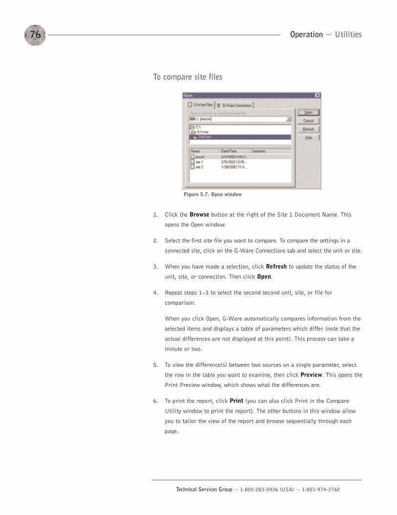
Operation ~ Utilities76
Technical Services Group ~ 1-800-283-5936 (USA) ~ 1-801-974-3760
To compare site files
1. Click the Browse button at the right of the Site 1 Document Name. This
opens the Open window.
2. Select the first site file you want to compare. To compare the settings in a
connected site, click on the G-Ware Connections tab and select the unit or site.
3. When you have made a selection, click Refresh to update the status of the
unit, site, or connection. Then click Open.
4. Repeat steps 1—3 to select the second second unit, site, or file for
comparison.
When you click Open, G-Ware automatically compares information from the
selected items and displays a table of parameters which differ (note that the
actual differences are not displayed at this point). This process can take a
minute or two.
5. To view the difference(s) between two sources on a single parameter, select
the row in the table you want to examine, then click Preview. This opens the
Print Preview window, which shows what the differences are.
6. To print the report, click Print (you can also click Print in the Compare
Utility window to print the report). The other buttons in this window allow
you to tailor the view of the report and browse sequentially through each
page.
Figure 5.7. Open window
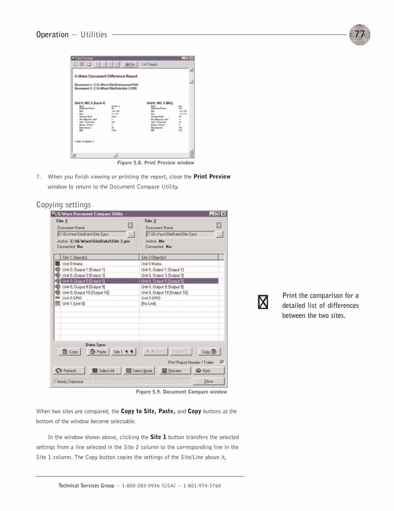
77Operation ~ Utilities
Technical Services Group ~ 1-800-283-5936 (USA) ~ 1-801-974-3760
7. When you finish viewing or printing the report, close the Print Preview
window to return to the Document Compare Utility.
Copying settings
When two sites are compared, the Copy to Site, Paste, and Copy buttons at the
bottom of the window become selectable.
In the window shown above, clicking the Site 1 button transfers the selected
settings from a line selected in the Site 2 column to the corresponding line in the
Site 1 column. The Copy button copies the settings of the Site/Line above it,
Figure 5.8. Print Preview window
Figure 5.9. Document Compare window
Print the comparison for adetailed list of differencesbetween the two sites.
��
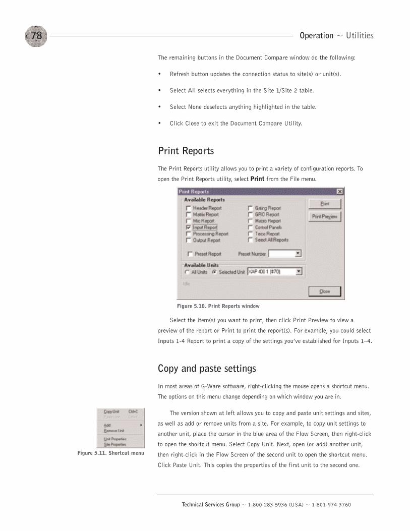
The remaining buttons in the Document Compare window do the following:
• Refresh button updates the connection status to site(s) or unit(s).
• Select All selects everything in the Site 1/Site 2 table.
• Select None deselects anything highlighted in the table.
• Click Close to exit the Document Compare Utility.
Print Reports
The Print Reports utility allows you to print a variety of configuration reports. To
open the Print Reports utility, select Print from the File menu.
Select the item(s) you want to print, then click Print Preview to view a
preview of the report or Print to print the report(s). For example, you could select
Inputs 1-4 Report to print a copy of the settings you’ve established for Inputs 1—4.
Copy and paste settings
In most areas of G-Ware software, right-clicking the mouse opens a shortcut menu.
The options on this menu change depending on which window you are in.
The version shown at left allows you to copy and paste unit settings and sites,
as well as add or remove units from a site. For example, to copy unit settings to
another unit, place the cursor in the blue area of the Flow Screen, then right-click
to open the shortcut menu. Select Copy Unit. Next, open (or add) another unit,
then right-click in the Flow Screen of the second unit to open the shortcut menu.
Click Paste Unit. This copies the properties of the first unit to the second one.
Operation ~ Utilities78
Technical Services Group ~ 1-800-283-5936 (USA) ~ 1-801-974-3760
Figure 5.10. Print Reports window
Figure 5.11. Shortcut menu
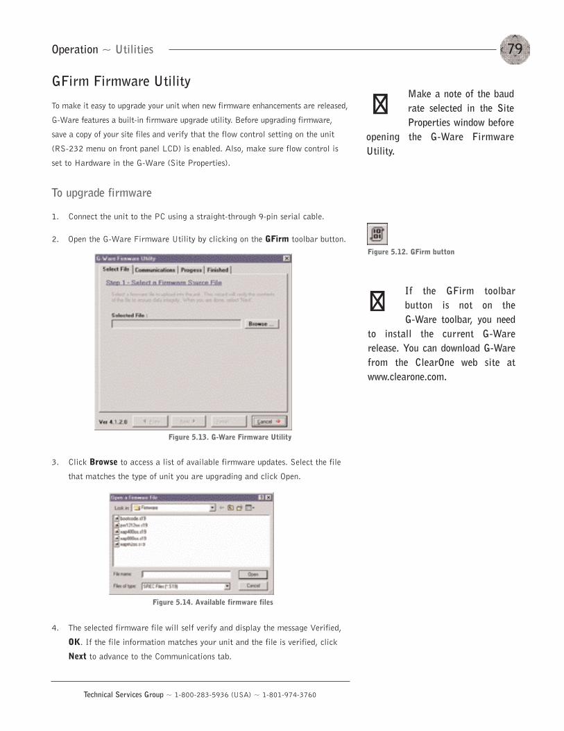
79Operation ~ Utilities
Technical Services Group ~ 1-800-283-5936 (USA) ~ 1-801-974-3760
GFirm Firmware Utility
To make it easy to upgrade your unit when new firmware enhancements are released,
G-Ware features a built-in firmware upgrade utility. Before upgrading firmware,
save a copy of your site files and verify that the flow control setting on the unit
(RS-232 menu on front panel LCD) is enabled. Also, make sure flow control is
set to Hardware in the G-Ware (Site Properties).
To upgrade firmware
1. Connect the unit to the PC using a straight-through 9-pin serial cable.
2. Open the G-Ware Firmware Utility by clicking on the GFirm toolbar button.
3. Click Browse to access a list of available firmware updates. Select the file
that matches the type of unit you are upgrading and click Open.
4. The selected firmware file will self verify and display the message Verified,
OK. If the file information matches your unit and the file is verified, click
Next to advance to the Communications tab.
If the GFirm toolbarbutton is not on the G-Ware toolbar, you need
to install the current G-Warerelease. You can download G-Warefrom the ClearOne web site atwww.clearone.com.
��
Figure 5.12. GFirm button
Figure 5.13. G-Ware Firmware Utility
Figure 5.14. Available firmware files
Make a note of the baudrate selected in the SiteProperties window before
opening the G-Ware FirmwareUtility.
��
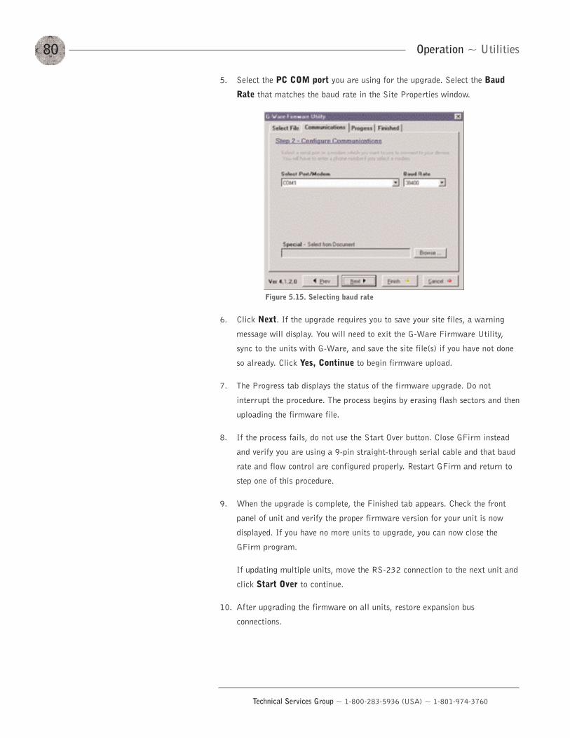
Operation ~ Utilities80
Technical Services Group ~ 1-800-283-5936 (USA) ~ 1-801-974-3760
5. Select the PC COM port you are using for the upgrade. Select the Baud
Rate that matches the baud rate in the Site Properties window.
6. Click Next. If the upgrade requires you to save your site files, a warning
message will display. You will need to exit the G-Ware Firmware Utility,
sync to the units with G-Ware, and save the site file(s) if you have not done
so already. Click Yes, Continue to begin firmware upload.
7. The Progress tab displays the status of the firmware upgrade. Do not
interrupt the procedure. The process begins by erasing flash sectors and then
uploading the firmware file.
8. If the process fails, do not use the Start Over button. Close GFirm instead
and verify you are using a 9-pin straight-through serial cable and that baud
rate and flow control are configured properly. Restart GFirm and return to
step one of this procedure.
9. When the upgrade is complete, the Finished tab appears. Check the front
panel of unit and verify the proper firmware version for your unit is now
displayed. If you have no more units to upgrade, you can now close the
GFirm program.
If updating multiple units, move the RS-232 connection to the next unit and
click Start Over to continue.
10. After upgrading the firmware on all units, restore expansion bus
connections.
Figure 5.15. Selecting baud rate
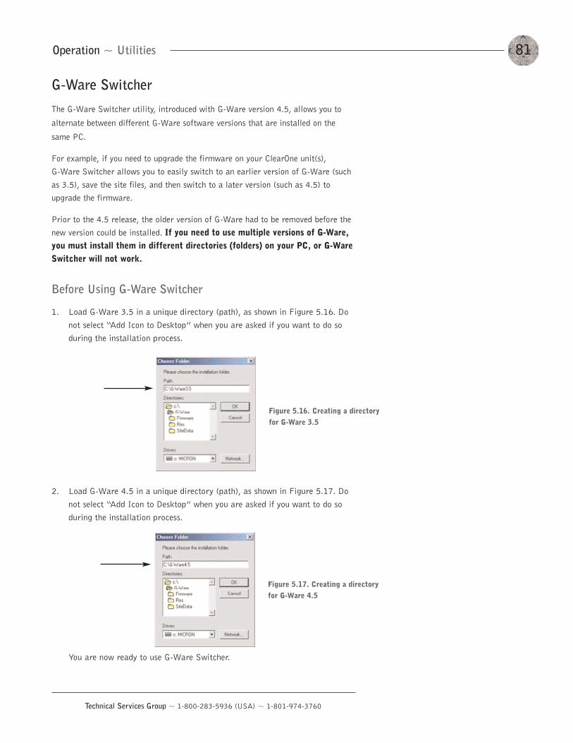
81Operation ~ Utilities
Technical Services Group ~ 1-800-283-5936 (USA) ~ 1-801-974-3760
G-Ware Switcher
The G-Ware Switcher utility, introduced with G-Ware version 4.5, allows you to
alternate between different G-Ware software versions that are installed on the
same PC.
For example, if you need to upgrade the firmware on your ClearOne unit(s), G-Ware Switcher allows you to easily switch to an earlier version of G-Ware (suchas 3.5), save the site files, and then switch to a later version (such as 4.5) toupgrade the firmware.
Prior to the 4.5 release, the older version of G-Ware had to be removed before thenew version could be installed. If you need to use multiple versions of G-Ware,you must install them in different directories (folders) on your PC, or G-WareSwitcher will not work.
Before Using G-Ware Switcher
1. Load G-Ware 3.5 in a unique directory (path), as shown in Figure 5.16. Donot select “Add Icon to Desktop” when you are asked if you want to do soduring the installation process.
2. Load G-Ware 4.5 in a unique directory (path), as shown in Figure 5.17. Donot select “Add Icon to Desktop” when you are asked if you want to do soduring the installation process.
You are now ready to use G-Ware Switcher.
Figure 5.16. Creating a directoryfor G-Ware 3.5
Figure 5.17. Creating a directoryfor G-Ware 4.5
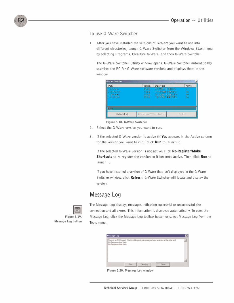
Operation ~ Utilities82
Technical Services Group ~ 1-800-283-5936 (USA) ~ 1-801-974-3760
To use G-Ware Switcher
1. After you have installed the versions of G-Ware you want to use into
different directories, launch G-Ware Switcher from the Windows Start menu
by selecting Programs, ClearOne G-Ware, and then G-Ware Switcher.
The G-Ware Switcher Utility window opens. G-Ware Switcher automatically
searches the PC for G-Ware software versions and displays them in the
window.
2. Select the G-Ware version you want to run.
3. If the selected G-Ware version is active (if Yes appears in the Active columnfor the version you want to run), click Run to launch it.
If the selected G-Ware version is not active, click Re-Register/MakeShortcuts to re-register the version so it becomes active. Then click Run tolaunch it.
If you have installed a version of G-Ware that isn’t displayed in the G-Ware
Switcher window, click Refresh. G-Ware Switcher will locate and display the
version.
Message Log
The Message Log displays messages indicating successful or unsuccessful site
connection and all errors. This information is displayed automatically. To open the
Message Log, click the Message Log toolbar button or select Message Log from the
Tools menu.
Figure 5.18. G-Ware Switcher
Figure 5.19. Message Log button
Figure 5.20. Message Log window
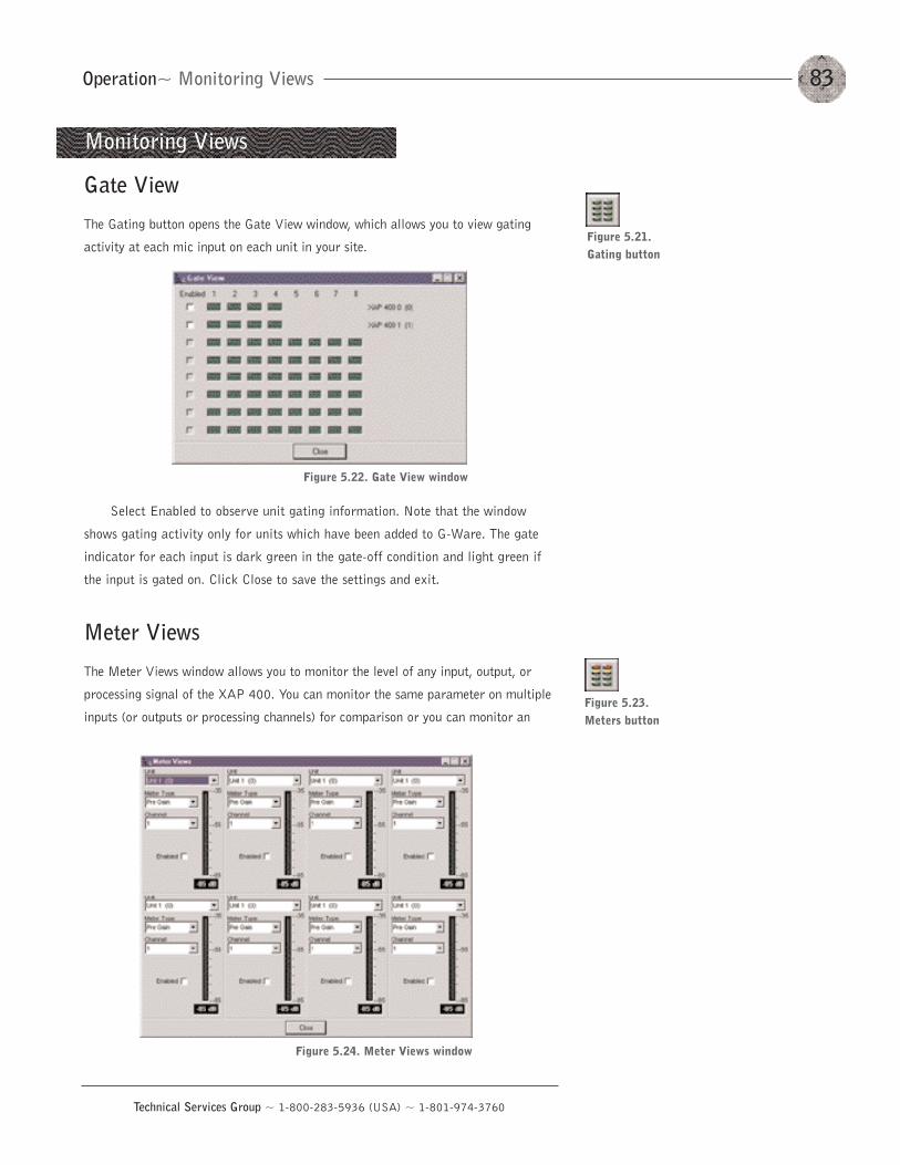
83Operation~ Monitoring Views
Technical Services Group ~ 1-800-283-5936 (USA) ~ 1-801-974-3760
Figure 5.23. Meters button
Gate View
The Gating button opens the Gate View window, which allows you to view gating
activity at each mic input on each unit in your site.
Select Enabled to observe unit gating information. Note that the window
shows gating activity only for units which have been added to G-Ware. The gate
indicator for each input is dark green in the gate-off condition and light green if
the input is gated on. Click Close to save the settings and exit.
Meter Views
The Meter Views window allows you to monitor the level of any input, output, or
processing signal of the XAP 400. You can monitor the same parameter on multiple
inputs (or outputs or processing channels) for comparison or you can monitor an
Figure 5.22. Gate View window
Figure 5.21. Gating button
Monitoring Views
Figure 5.24. Meter Views window
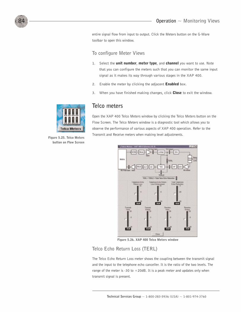
Operation ~ Monitoring Views84
Technical Services Group ~ 1-800-283-5936 (USA) ~ 1-801-974-3760
entire signal flow from input to output. Click the Meters button on the G-Ware
toolbar to open this window.
To configure Meter Views
1. Select the unit number, meter type, and channel you want to use. Note
that you can configure the meters such that you can monitor the same input
signal as it makes its way through various stages in the XAP 400.
2. Enable the meter by clicking the adjacent Enabled box.
3. When you have finished making changes, click Close to exit the window.
Telco meters
Open the XAP 400 Telco Meters window by clicking the Telco Meters button on the
Flow Screen. The Telco Meters window is a diagnostic tool which allows you to
observe the performance of various aspects of XAP 400 operation. Refer to the
Transmit and Receive meters when making level adjustments.
Telco Echo Return Loss (TERL)
The Telco Echo Return Loss meter shows the coupling between the transmit signal
and the input to the telephone echo canceller. It is the ratio of the two levels. The
range of the meter is -30 to +20dB. It is a peak meter and updates only when
transmit signal is present.
Figure 5.26. XAP 400 Telco Meters window
Figure 5.25. Telco Meters button on Flow Screen
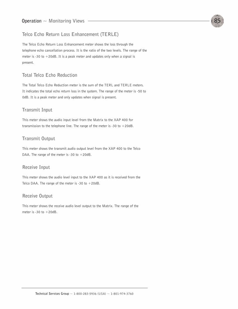
85Operation ~ Monitoring Views
Technical Services Group ~ 1-800-283-5936 (USA) ~ 1-801-974-3760
Telco Echo Return Loss Enhancement (TERLE)
The Telco Echo Return Loss Enhancement meter shows the loss through the
telephone echo cancellation process. It is the ratio of the two levels. The range of the
meter is -30 to +20dB. It is a peak meter and updates only when a signal is
present.
Total Telco Echo Reduction
The Total Telco Echo Reduction meter is the sum of the TERL and TERLE meters.
It indicates the total echo return loss in the system. The range of the meter is -50 to
0dB. It is a peak meter and only updates when signal is present.
Transmit Input
This meter shows the audio input level from the Matrix to the XAP 400 for
transmission to the telephone line. The range of the meter is -30 to +20dB.
Transmit Output
This meter shows the transmit audio output level from the XAP 400 to the Telco
DAA. The range of the meter is -30 to +20dB.
Receive Input
This meter shows the audio level input to the XAP 400 as it is received from the
Telco DAA. The range of the meter is -30 to +20dB.
Receive Output
This meter shows the receive audio level output to the Matrix. The range of the
meter is -30 to +20dB.

86
Technical Services Group ~ 1-800-283-5936 (USA) ~ 1-801-974-3760
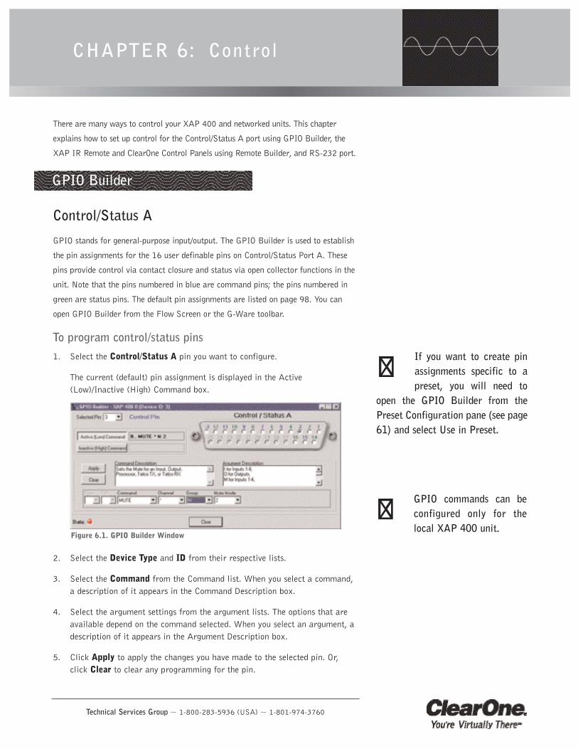
Technical Services Group ~ 1-800-283-5936 (USA) ~ 1-801-974-3760
There are many ways to control your XAP 400 and networked units. This chapter
explains how to set up control for the Control/Status A port using GPIO Builder, the
XAP IR Remote and ClearOne Control Panels using Remote Builder, and RS-232 port.
Control/Status A
GPIO stands for general-purpose input/output. The GPIO Builder is used to establish
the pin assignments for the 16 user definable pins on Control/Status Port A. These
pins provide control via contact closure and status via open collector functions in the
unit. Note that the pins numbered in blue are command pins; the pins numbered in
green are status pins. The default pin assignments are listed on page 98. You can
open GPIO Builder from the Flow Screen or the G-Ware toolbar.
To program control/status pins1. Select the Control/Status A pin you want to configure.
The current (default) pin assignment is displayed in the Active(Low)/Inactive (High) Command box.
2. Select the Device Type and ID from their respective lists.
3. Select the Command from the Command list. When you select a command,a description of it appears in the Command Description box.
4. Select the argument settings from the argument lists. The options that areavailable depend on the command selected. When you select an argument, adescription of it appears in the Argument Description box.
5. Click Apply to apply the changes you have made to the selected pin. Or,click Clear to clear any programming for the pin.
CHAPTER 6: Control
GPIO Builder
If you want to create pinassignments specific to apreset, you will need to
open the GPIO Builder from thePreset Configuration pane (see page61) and select Use in Preset.
��
Figure 6.1. GPIO Builder Window
GPIO commands can beconfigured only for thelocal XAP 400 unit.
��
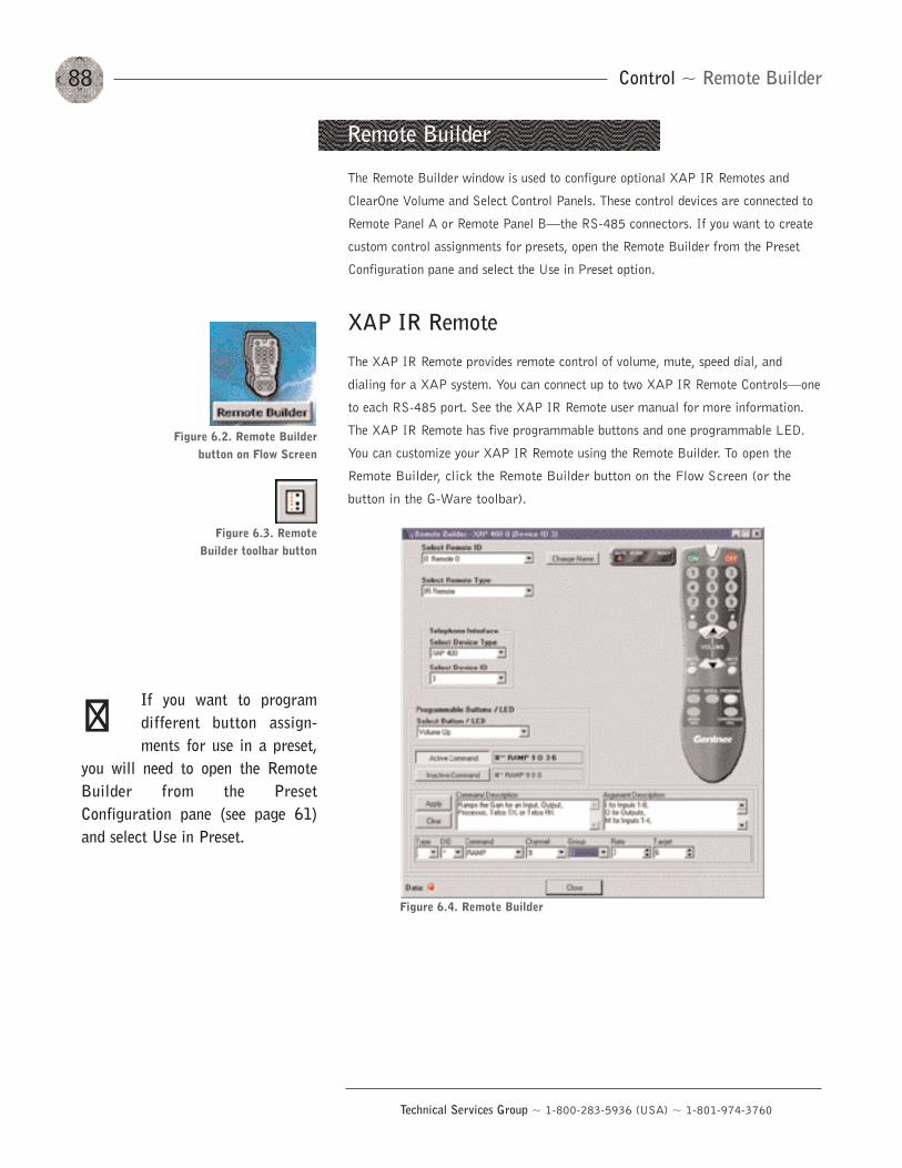
88
Technical Services Group ~ 1-800-283-5936 (USA) ~ 1-801-974-3760
Control ~ Remote Builder
The Remote Builder window is used to configure optional XAP IR Remotes and
ClearOne Volume and Select Control Panels. These control devices are connected to
Remote Panel A or Remote Panel B–the RS-485 connectors. If you want to create
custom control assignments for presets, open the Remote Builder from the Preset
Configuration pane and select the Use in Preset option.
XAP IR Remote
The XAP IR Remote provides remote control of volume, mute, speed dial, and
dialing for a XAP system. You can connect up to two XAP IR Remote Controls–one
to each RS-485 port. See the XAP IR Remote user manual for more information.
The XAP IR Remote has five programmable buttons and one programmable LED.
You can customize your XAP IR Remote using the Remote Builder. To open the
Remote Builder, click the Remote Builder button on the Flow Screen (or the
button in the G-Ware toolbar).
Remote Builder
Figure 6.4. Remote Builder
Figure 6.2. Remote Builderbutton on Flow Screen
Figure 6.3. RemoteBuilder toolbar button
If you want to programdifferent button assign-ments for use in a preset,
you will need to open the RemoteBuilder from the PresetConfiguration pane (see page 61)and select Use in Preset.
��
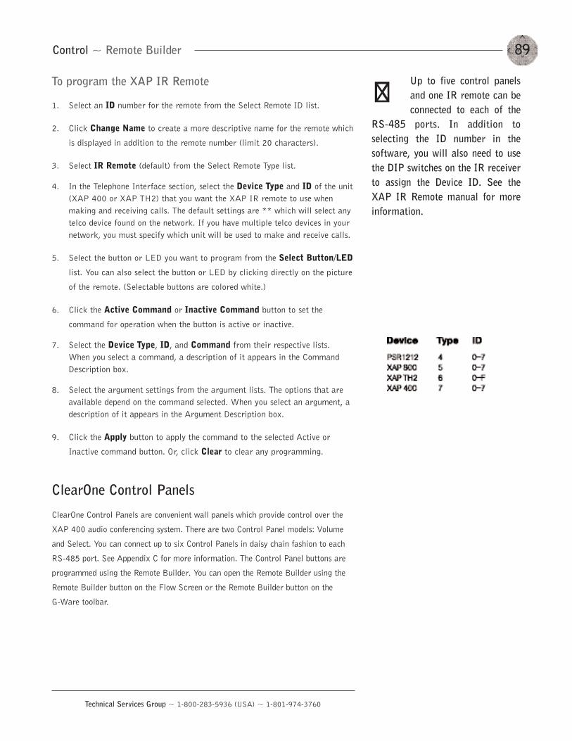
89
Technical Services Group ~ 1-800-283-5936 (USA) ~ 1-801-974-3760
Control ~ Remote Builder
To program the XAP IR Remote
1. Select an ID number for the remote from the Select Remote ID list.
2. Click Change Name to create a more descriptive name for the remote which
is displayed in addition to the remote number (limit 20 characters).
3. Select IR Remote (default) from the Select Remote Type list.
4. In the Telephone Interface section, select the Device Type and ID of the unit(XAP 400 or XAP TH2) that you want the XAP IR remote to use whenmaking and receiving calls. The default settings are ** which will select anytelco device found on the network. If you have multiple telco devices in yournetwork, you must specify which unit will be used to make and receive calls.
5. Select the button or LED you want to program from the Select Button/LED
list. You can also select the button or LED by clicking directly on the picture
of the remote. (Selectable buttons are colored white.)
6. Click the Active Command or Inactive Command button to set the
command for operation when the button is active or inactive.
7. Select the Device Type, ID, and Command from their respective lists.When you select a command, a description of it appears in the CommandDescription box.
8. Select the argument settings from the argument lists. The options that areavailable depend on the command selected. When you select an argument, adescription of it appears in the Argument Description box.
9. Click the Apply button to apply the command to the selected Active or
Inactive command button. Or, click Clear to clear any programming.
ClearOne Control Panels
ClearOne Control Panels are convenient wall panels which provide control over the
XAP 400 audio conferencing system. There are two Control Panel models: Volume
and Select. You can connect up to six Control Panels in daisy chain fashion to each
RS-485 port. See Appendix C for more information. The Control Panel buttons are
programmed using the Remote Builder. You can open the Remote Builder using the
Remote Builder button on the Flow Screen or the Remote Builder button on the
G-Ware toolbar.
Up to five control panelsand one IR remote can beconnected to each of the
RS-485 ports. In addition toselecting the ID number in thesoftware, you will also need to usethe DIP switches on the IR receiverto assign the Device ID. See theXAP IR Remote manual for moreinformation.
��
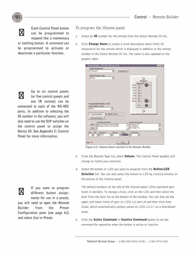
90
Technical Services Group ~ 1-800-283-5936 (USA) ~ 1-801-974-3760
Control ~ Remote Builder
To program the Volume panel
1. Select an ID number for the remote from the Select Remote ID list.
2. Click Change Name to create a more descriptive name (limit 20
characters) for the remote which is displayed in addition to the remote
number in the Select Remote ID list. The name is also updated on the
graphic label.
3. From the Remote Type list, select Volume. The Control Panel graphic will
change to match your selection.
4. Select the button or LED you want to program from the Button/LED
Selection list. You can also select the button or LED by clicking directly on
the picture of the Volume panel.
The default numbers on the left of the Volume panel LEDs represent gain
levels in decibels. To change a level, click on the LED and then select the
level from the Gain list at the bottom of the window. You can also set the
upper and lower limits of gain on LEDs L2 and L8 and then click Auto
Scale, which automatically assigns values to LEDs L3-L7 on a distributed
scale.
5. Click the Active Command or Inactive Command button to set the
command for operation when the button is active or inactive.
Figure 6.5. Volume Panel selected in the Remote Builder
Each Control Panel buttoncan be programmed torespond like a momentary
or latching button. A command canbe programmed to activate ordeactivate a particular function.
��
If you want to programdifferent button assign-ments for use in a preset,
you will need to open the RemoteBuilder from the PresetConfiguration pane (see page 61)and select Use in Preset.
��
Up to six control panels(or five control panels andone IR remote) can be
connected to each of the RS-485ports. In addition to selecting theID number in the software, you willalso need to use the DIP switches onthe control panel to assign theDevice ID. See Appendix C: ControlPanel for more information.
��
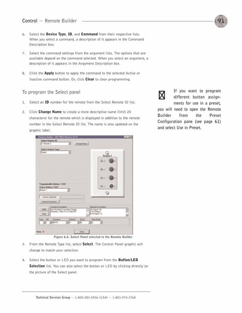
91
Technical Services Group ~ 1-800-283-5936 (USA) ~ 1-801-974-3760
Control ~ Remote Builder
6. Select the Device Type, ID, and Command from their respective lists.When you select a command, a description of it appears in the CommandDescription box.
7. Select the command settings from the argument lists. The options that areavailable depend on the command selected. When you select an argument, adescription of it appears in the Argument Description box.
8. Click the Apply button to apply the command to the selected Active or
Inactive command button. Or, click Clear to clear programming.
To program the Select panel
1. Select an ID number for the remote from the Select Remote ID list.
2. Click Change Name to create a more descriptive name (limit 20
characters) for the remote which is displayed in addition to the remote
number in the Select Remote ID list. The name is also updated on the
graphic label.
3. From the Remote Type list, select Select. The Control Panel graphic will
change to match your selection.
4. Select the button or LED you want to program from the Button/LED
Selection list. You can also select the button or LED by clicking directly on
the picture of the Select panel.
Figure 6.6. Select Panel selected in the Remote Builder
If you want to programdifferent button assign-ments for use in a preset,
you will need to open the RemoteBuilder from the PresetConfiguration pane (see page 61)and select Use in Preset.
��
92
Technical Services Group ~ 1-800-283-5936 (USA) ~ 1-801-974-3760
Control ~ RS-232 Port
5. Click the Active Command or Inactive Command button to set the
command for operation when the button is active or inactive.
6. Select the Device Type, ID, and Command from their respective lists.When you select a command, a description of it appears in the CommandDescription box.
7. Select the command settings from the argument lists. The options that areavailable depend on the command selected. When you select an argument, adescription of it appears in the Argument Description box.
8. Click the Apply button to apply the command to the selected Active or
Inactive command button. Or, click Clear to clear programming.
Remote Modem Access
You can access the unit remotely through a modem connected to the serial port. To
enable this feature, configure the port for modem mode.
When in modem mode, the serial port will send an initialization string to the
modem upon entering the mode or upon power-up of the unit. You program the
initialization string in Site Properties window in G-Ware. Typical configurations
you set with the initialization string include setting a fixed baud rate for the unit
and setting up auto-answer parameters.
You must enter a password before you can control the system this way. The
default password is blank (a carriage return). You can change it to any
combination of letters and/or numbers up to 12 characters. It is not case-sensitive.
When you establish a valid serial connection with the unit in modem mode,
the unit will wait for a carriage return. When you have entered a carriage return,
the system will prompt you to enter the password. If there is no activity for five
minutes on the serial port while in modem mode, the unit will re-prompt for the
password.
Serial commands
Serial commands can be passed through the XAP 400 RS-232 port using Hyper
Terminal, touch panels, or other compatible remote control devices. To learn more
about serial commands, see Appendix E.
RS-232 Port
The modem password iscreated in the UnitProperties window (see
page 26) or by using the MPASSserial command (see page 131).
��
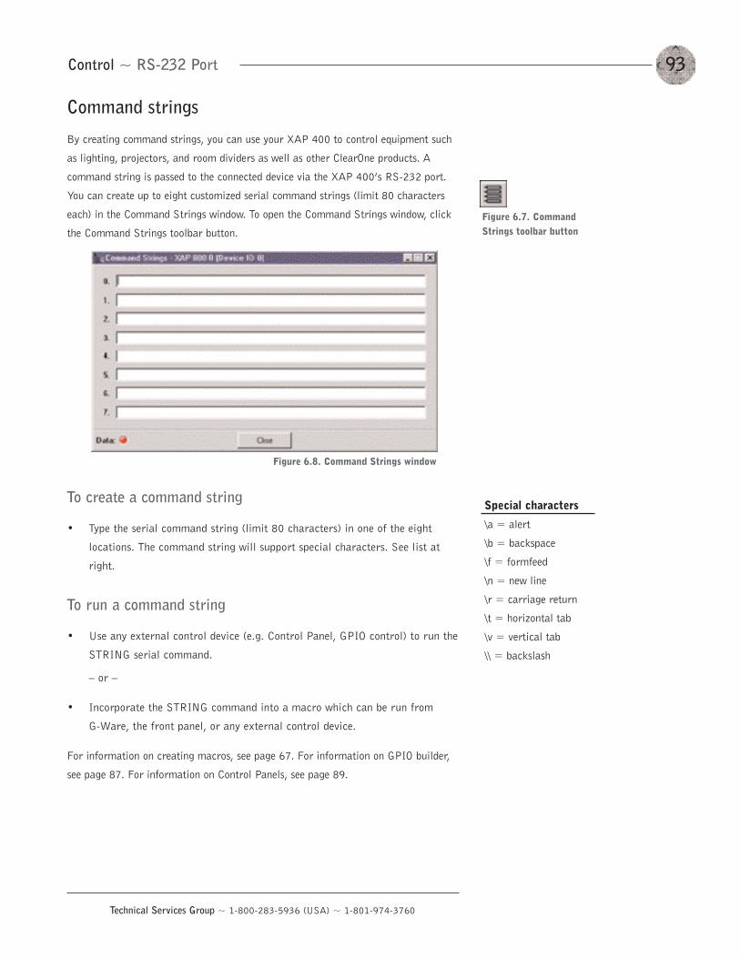
93
Technical Services Group ~ 1-800-283-5936 (USA) ~ 1-801-974-3760
Command strings
By creating command strings, you can use your XAP 400 to control equipment such
as lighting, projectors, and room dividers as well as other ClearOne products. A
command string is passed to the connected device via the XAP 400’s RS-232 port.
You can create up to eight customized serial command strings (limit 80 characters
each) in the Command Strings window. To open the Command Strings window, click
the Command Strings toolbar button.
To create a command string
• Type the serial command string (limit 80 characters) in one of the eight
locations. The command string will support special characters. See list at
right.
To run a command string
• Use any external control device (e.g. Control Panel, GPIO control) to run the
STRING serial command.
— or —
• Incorporate the STRING command into a macro which can be run from
G-Ware, the front panel, or any external control device.
For information on creating macros, see page 67. For information on GPIO builder,
see page 87. For information on Control Panels, see page 89.
Control ~ RS-232 Port
Figure 6.7. Command Strings toolbar button
Figure 6.8. Command Strings window
Special characters
\a = alert
\b = backspace
\f = formfeed
\n = new line
\r = carriage return
\t = horizontal tab
\v = vertical tab
\\ = backslash

94
Technical Services Group ~ 1-800-283-5936 (USA) ~ 1-801-974-3760
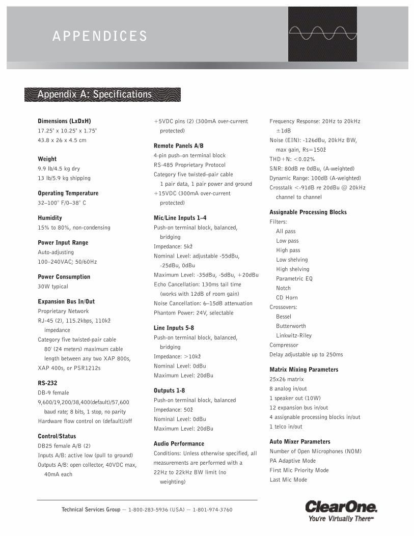
Technical Services Group ~ 1-800-283-5936 (USA) ~ 1-801-974-3760
APPENDICES
Dimensions (LxDxH)
17.25" x 10.25" x 1.75"
43.8 x 26 x 4.5 cm
Weight
9.9 lb/4.5 kg dry
13 lb/5.9 kg shipping
Operating Temperature
32—100° F/0—38° C
Humidity
15% to 80%, non-condensing
Power Input Range
Auto-adjusting
100—240VAC; 50/60Hz
Power Consumption
30W typical
Expansion Bus In/Out
Proprietary Network
RJ-45 (2), 115.2kbps, 110kž
impedance
Category five twisted-pair cable
80' (24 meters) maximum cable
length between any two XAP 800s,
XAP 400s, or PSR1212s
RS-232
DB-9 female
9,600/19,200/38,400(default)/57,600
baud rate; 8 bits, 1 stop, no parity
Hardware flow control on (default)/off
Control/Status
DB25 female A/B (2)
Inputs A/B: active low (pull to ground)
Outputs A/B: open collector, 40VDC max,
40mA each
+5VDC pins (2) (300mA over-current
protected)
Remote Panels A/B
4-pin push—on terminal block
RS-485 Proprietary Protocol
Category five twisted—pair cable
1 pair data, 1 pair power and ground
+15VDC (300mA over-current
protected)
Mic/Line Inputs 1—4
Push-on terminal block, balanced,
bridging
Impedance: 5kž
Nominal Level: adjustable -55dBu,
-25dBu, 0dBu
Maximum Level: -35dBu, -5dBu, +20dBu
Echo Cancellation: 130ms tail time
(works with 12dB of room gain)
Noise Cancellation: 6—15dB attenuation
Phantom Power: 24V, selectable
Line Inputs 5-8
Push-on terminal block, balanced,
bridging
Impedance: >10kž
Nominal Level: 0dBu
Maximum Level: 20dBu
Outputs 1-8
Push-on terminal block, balanced
Impedance: 50ž
Nominal Level: 0dBu
Maximum Level: 20dBu
Audio Performance
Conditions: Unless otherwise specified, all
measurements are performed with a
22Hz to 22kHz BW limit (no
weighting)
Frequency Response: 20Hz to 20kHz
±1dB
Noise (EIN): -126dBu, 20kHz BW,
max gain, Rs=150ž
THD+N: <0.02%
SNR: 80dB re 0dBu, (A-weighted)
Dynamic Range: 100dB (A-weighted)
Crosstalk <-91dB re 20dBu @ 20kHz
channel to channel
Assignable Processing Blocks
Filters:
All pass
Low pass
High pass
Low shelving
High shelving
Parametric EQ
Notch
CD Horn
Crossovers:
Bessel
Butterworth
Linkwitz-Riley
Compressor
Delay adjustable up to 250ms
Matrix Mixing Parameters
25x26 matrix
8 analog in/out
1 speaker out (10W)
12 expansion bus in/out
4 assignable processing blocks in/out
1 telco in/out
Auto Mixer Parameters
Number of Open Microphones (NOM)
PA Adaptive Mode
First Mic Priority Mode
Last Mic Mode
Appendix A: Specifications
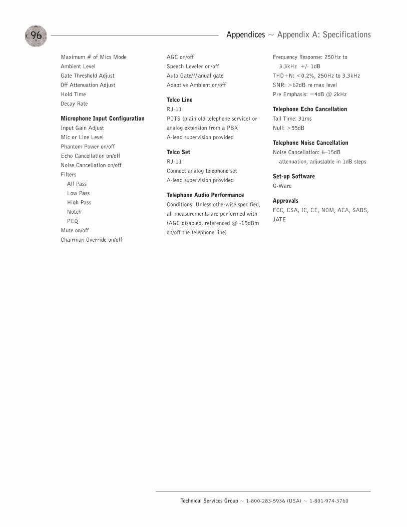
96
Technical Services Group ~ 1-800-283-5936 (USA) ~ 1-801-974-3760
Appendices ~ Appendix A: Specifications
Maximum # of Mics Mode
Ambient Level
Gate Threshold Adjust
Off Attenuation Adjust
Hold Time
Decay Rate
Microphone Input Configuration
Input Gain Adjust
Mic or Line Level
Phantom Power on/off
Echo Cancellation on/off
Noise Cancellation on/off
Filters
All Pass
Low Pass
High Pass
Notch
PEQ
Mute on/off
Chairman Override on/off
AGC on/off
Speech Leveler on/off
Auto Gate/Manual gate
Adaptive Ambient on/off
Telco Line
RJ-11
POTS (plain old telephone service) or
analog extension from a PBX
A-lead supervision provided
Telco Set
RJ-11
Connect analog telephone set
A-lead supervision provided
Telephone Audio Performance
Conditions: Unless otherwise specified,
all measurements are performed with
(AGC disabled, referenced @ -15dBm
on/off the telephone line)
Frequency Response: 250Hz to
3.3kHz +/- 1dB
THD+N: <0.2%, 250Hz to 3.3kHz
SNR: >62dB re max level
Pre Emphasis: =4dB @ 2kHz
Telephone Echo Cancellation
Tail Time: 31ms
Null: >55dB
Telephone Noise Cancellation
Noise Cancellation: 6—15dB
attenuation, adjustable in 1dB steps
Set-up Software
G-Ware
Approvals
FCC, CSA, IC, CE, NOM, ACA, SABS,
JATE
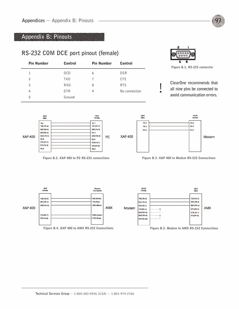
97
Technical Services Group ~ 1-800-283-5936 (USA) ~ 1-801-974-3760
Appendices ~ Appendix B: Pinouts
Appendix B: Pinouts
RS-232 COM DCE port pinout (female)
Pin Number Control Pin Number Control
1 DCD 6 DSR
2 TXD 7 CTS
3 RXD 8 RTS
4 DTR 9 No connection
5 Ground
Figure B.1. RS-232 connector
Figure B.2. XAP 400 to PC RS-232 connections Figure B.3. XAP 400 to Modem RS-232 Connections
Figure B.5. Modem to AMX RS-232 ConnectionsFigure B.4. XAP 400 to AMX RS-232 Connections
ClearOne recommends thatall nine pins be connected toavoid communication errors.
!
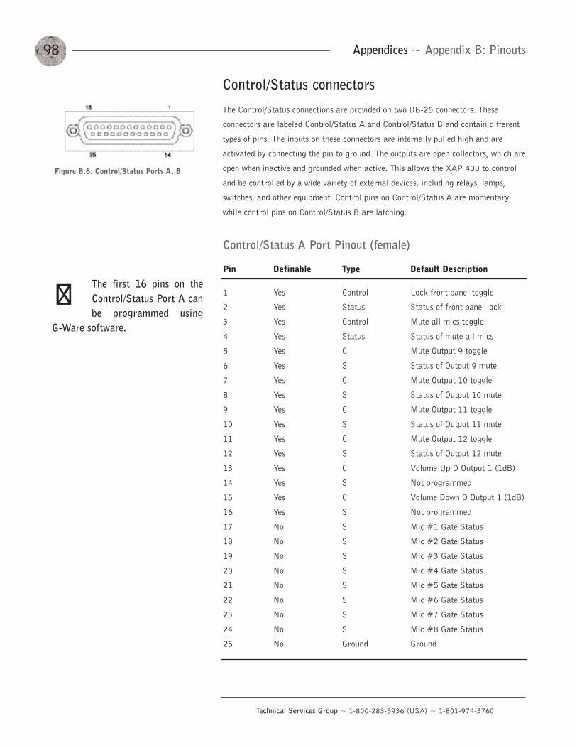
98
Technical Services Group ~ 1-800-283-5936 (USA) ~ 1-801-974-3760
Control/Status A Port Pinout (female)
Pin Definable Type Default Description
1 Yes Control Lock front panel toggle
2 Yes Status Status of front panel lock
3 Yes Control Mute all mics toggle
4 Yes Status Status of mute all mics
5 Yes C Mute Output 9 toggle
6 Yes S Status of Output 9 mute
7 Yes C Mute Output 10 toggle
8 Yes S Status of Output 10 mute
9 Yes C Mute Output 11 toggle
10 Yes S Status of Output 11 mute
11 Yes C Mute Output 12 toggle
12 Yes S Status of Output 12 mute
13 Yes C Volume Up D Output 1 (1dB)
14 Yes S Not programmed
15 Yes C Volume Down D Output 1 (1dB)
16 Yes S Not programmed
17 No S Mic #1 Gate Status
18 No S Mic #2 Gate Status
19 No S Mic #3 Gate Status
20 No S Mic #4 Gate Status
21 No S Mic #5 Gate Status
22 No S Mic #6 Gate Status
23 No S Mic #7 Gate Status
24 No S Mic #8 Gate Status
25 No Ground Ground
Figure B.6. Control/Status Ports A, B
Control/Status connectors
The Control/Status connections are provided on two DB-25 connectors. These
connectors are labeled Control/Status A and Control/Status B and contain different
types of pins. The inputs on these connectors are internally pulled high and are
activated by connecting the pin to ground. The outputs are open collectors, which are
open when inactive and grounded when active. This allows the XAP 400 to control
and be controlled by a wide variety of external devices, including relays, lamps,
switches, and other equipment. Control pins on Control/Status A are momentary
while control pins on Control/Status B are latching.
Appendices ~ Appendix B: Pinouts
The first 16 pins on theControl/Status Port A canbe programmed using
G-Ware software.
��
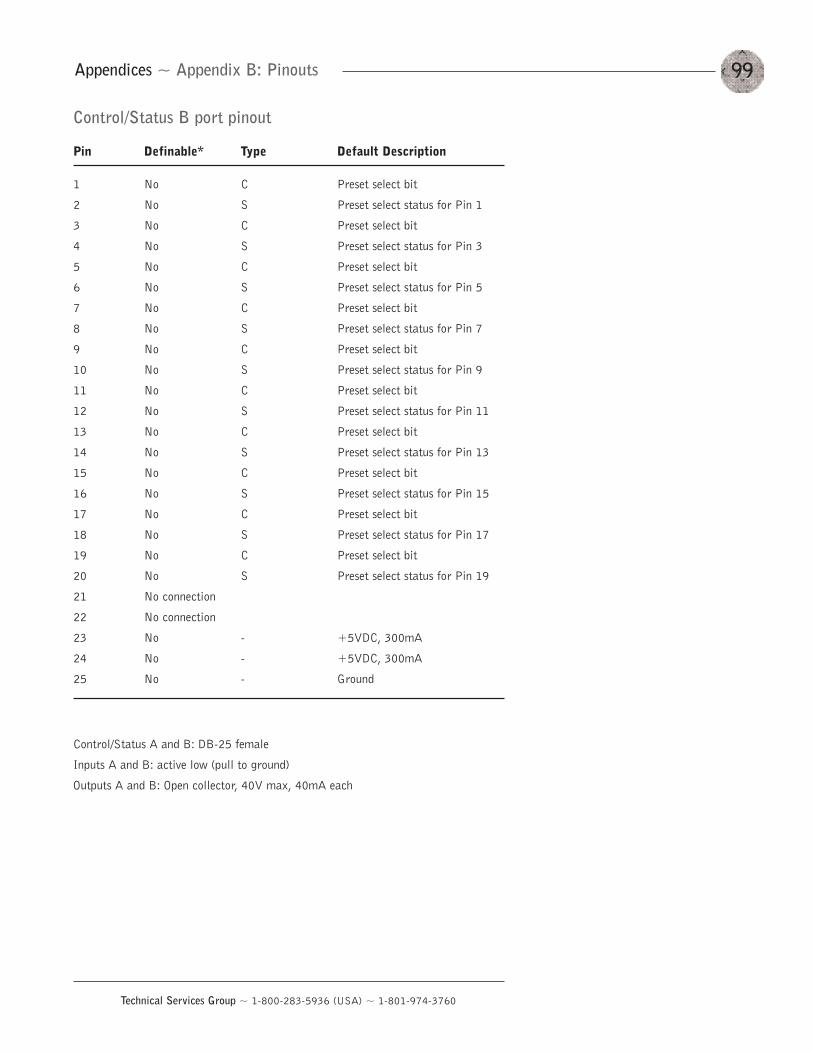
99
Technical Services Group ~ 1-800-283-5936 (USA) ~ 1-801-974-3760
Appendices ~ Appendix B: Pinouts
Control/Status B port pinout
Pin Definable* Type Default Description
1 No C Preset select bit
2 No S Preset select status for Pin 1
3 No C Preset select bit
4 No S Preset select status for Pin 3
5 No C Preset select bit
6 No S Preset select status for Pin 5
7 No C Preset select bit
8 No S Preset select status for Pin 7
9 No C Preset select bit
10 No S Preset select status for Pin 9
11 No C Preset select bit
12 No S Preset select status for Pin 11
13 No C Preset select bit
14 No S Preset select status for Pin 13
15 No C Preset select bit
16 No S Preset select status for Pin 15
17 No C Preset select bit
18 No S Preset select status for Pin 17
19 No C Preset select bit
20 No S Preset select status for Pin 19
21 No connection
22 No connection
23 No - +5VDC, 300mA
24 No - +5VDC, 300mA
25 No - Ground
Control/Status A and B: DB-25 female
Inputs A and B: active low (pull to ground)
Outputs A and B: Open collector, 40V max, 40mA each
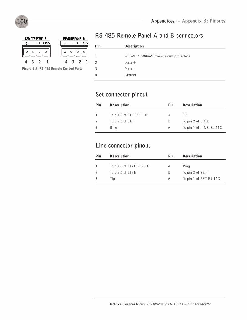
100
Technical Services Group ~ 1-800-283-5936 (USA) ~ 1-801-974-3760
Appendices ~ Appendix B: Pinouts
Set connector pinout
Pin Description Pin Description
1 To pin 6 of SET RJ-11C 4 Tip
2 To pin 5 of SET 5 To pin 2 of LINE
3 Ring 6 To pin 1 of LINE RJ-11C
Line connector pinout
Pin Description Pin Description
1 To pin 6 of LINE RJ-11C 4 Ring
2 To pin 5 of LINE 5 To pin 2 of SET
3 Tip 6 To pin 1 of SET RJ-11C
Figure B.7. RS-485 Remote Control Ports
4 3 2 1 4 3 2 1
RS-485 Remote Panel A and B connectors
Pin Description
1 +15VDC, 300mA (over-current protected)
2 Data +
3 Data —
4 Ground
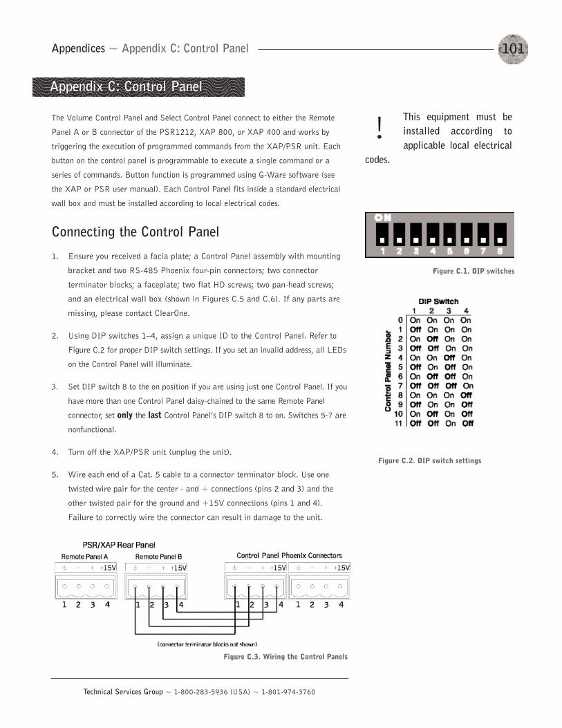
101
Technical Services Group ~ 1-800-283-5936 (USA) ~ 1-801-974-3760
Appendices ~ Appendix C: Control Panel
Appendix C: Control Panel
The Volume Control Panel and Select Control Panel connect to either the Remote
Panel A or B connector of the PSR1212, XAP 800, or XAP 400 and works by
triggering the execution of programmed commands from the XAP/PSR unit. Each
button on the control panel is programmable to execute a single command or a
series of commands. Button function is programmed using G-Ware software (see
the XAP or PSR user manual). Each Control Panel fits inside a standard electrical
wall box and must be installed according to local electrical codes.
Connecting the Control Panel
1. Ensure you received a facia plate; a Control Panel assembly with mounting
bracket and two RS-485 Phoenix four-pin connectors; two connector
terminator blocks; a faceplate; two flat HD screws; two pan-head screws;
and an electrical wall box (shown in Figures C.5 and C.6). If any parts are
missing, please contact ClearOne.
2. Using DIP switches 1—4, assign a unique ID to the Control Panel. Refer to
Figure C.2 for proper DIP switch settings. If you set an invalid address, all LEDs
on the Control Panel will illuminate.
3. Set DIP switch 8 to the on position if you are using just one Control Panel. If you
have more than one Control Panel daisy-chained to the same Remote Panel
connector, set only the last Control Panel’s DIP switch 8 to on. Switches 5-7 are
nonfunctional.
4. Turn off the XAP/PSR unit (unplug the unit).
5. Wire each end of a Cat. 5 cable to a connector terminator block. Use one
twisted wire pair for the center - and + connections (pins 2 and 3) and the
other twisted pair for the ground and +15V connections (pins 1 and 4).
Failure to correctly wire the connector can result in damage to the unit.
This equipment must beinstalled according toapplicable local electrical
codes.
!
Figure C.1. DIP switches
Figure C.2. DIP switch settings
Figure C.3. Wiring the Control Panels
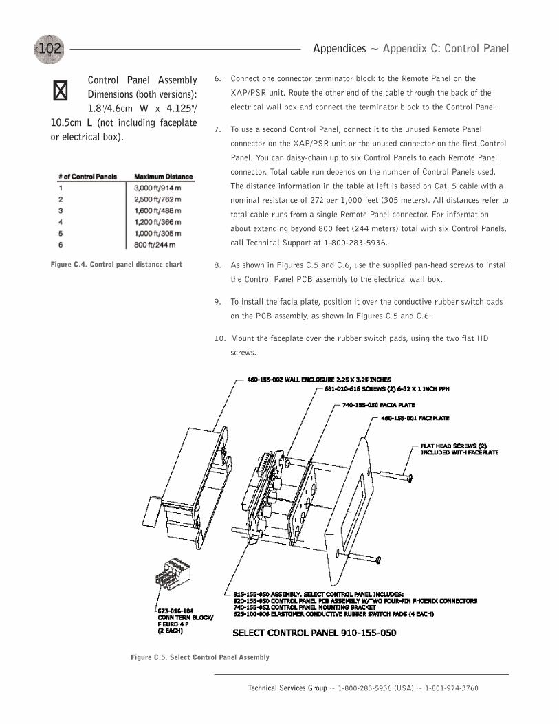
102
Technical Services Group ~ 1-800-283-5936 (USA) ~ 1-801-974-3760
Appendices ~ Appendix C: Control Panel
6. Connect one connector terminator block to the Remote Panel on the
XAP/PSR unit. Route the other end of the cable through the back of the
electrical wall box and connect the terminator block to the Control Panel.
7. To use a second Control Panel, connect it to the unused Remote Panel
connector on the XAP/PSR unit or the unused connector on the first Control
Panel. You can daisy-chain up to six Control Panels to each Remote Panel
connector. Total cable run depends on the number of Control Panels used.
The distance information in the table at left is based on Cat. 5 cable with a
nominal resistance of 27ž per 1,000 feet (305 meters). All distances refer to
total cable runs from a single Remote Panel connector. For information
about extending beyond 800 feet (244 meters) total with six Control Panels,
call Technical Support at 1-800-283-5936.
8. As shown in Figures C.5 and C.6, use the supplied pan-head screws to install
the Control Panel PCB assembly to the electrical wall box.
9. To install the facia plate, position it over the conductive rubber switch pads
on the PCB assembly, as shown in Figures C.5 and C.6.
10. Mount the faceplate over the rubber switch pads, using the two flat HD
screws.
Figure C.4. Control panel distance chart
Control Panel AssemblyDimensions (both versions):1.8"/4.6cm W x 4.125"/
10.5cm L (not including faceplateor electrical box).
��
Figure C.5. Select Control Panel Assembly
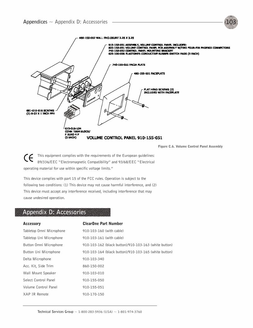
103
Technical Services Group ~ 1-800-283-5936 (USA) ~ 1-801-974-3760
Appendices ~ Appendix D: Accessories
Accessory ClearOne Part Number
Tabletop Omni Microphone 910-103-160 (with cable)
Tabletop Uni Microphone 910-103-161 (with cable)
Button Omni Microphone 910-103-162 (black button)/910-103-163 (white button)
Button Uni Microphone 910-103-164 (black button)/910-103-165 (white button)
Delta Microphone 910-103-340
Acc. Kit, Side Trim 860-150-002
Wall Mount Speaker 910-103-010
Select Control Panel 910-155-050
Volume Control Panel 910-155-051
XAP IR Remote 910-170-150
Appendix D: Accessories
Figure C.6. Volume Control Panel Assembly
This equipment complies with the requirements of the European guidelines:
89/336/EEC “Electromagnetic Compatibility” and 93/68/EEC “Electrical
operating material for use within specific voltage limits.”
This device complies with part 15 of the FCC rules. Operation is subject to the
following two conditions: (1) This device may not cause harmful interference, and (2)
This device must accept any interference received, including interference that may
cause undesired operation.
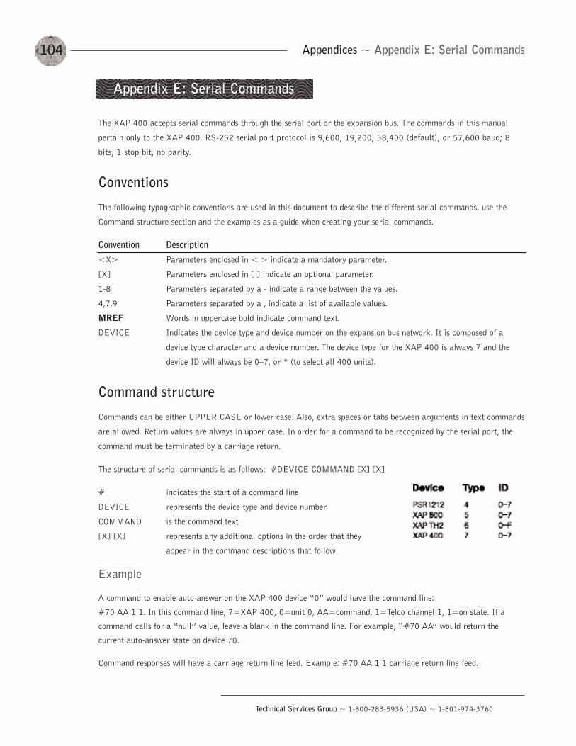
104
Technical Services Group ~ 1-800-283-5936 (USA) ~ 1-801-974-3760
Appendices ~ Appendix E: Serial Commands
The XAP 400 accepts serial commands through the serial port or the expansion bus. The commands in this manual
pertain only to the XAP 400. RS-232 serial port protocol is 9,600, 19,200, 38,400 (default), or 57,600 baud; 8
bits, 1 stop bit, no parity.
Conventions
The following typographic conventions are used in this document to describe the different serial commands. use the
Command structure section and the examples as a guide when creating your serial commands.
Convention Description<X> Parameters enclosed in < > indicate a mandatory parameter.
[X] Parameters enclosed in [ ] indicate an optional parameter.
1-8 Parameters separated by a - indicate a range between the values.
4,7,9 Parameters separated by a , indicate a list of available values.
MREF Words in uppercase bold indicate command text.
DEVICE Indicates the device type and device number on the expansion bus network. It is composed of a
device type character and a device number. The device type for the XAP 400 is always 7 and the
device ID will always be 0—7, or * (to select all 400 units).
Command structure
Commands can be either UPPER CASE or lower case. Also, extra spaces or tabs between arguments in text commands
are allowed. Return values are always in upper case. In order for a command to be recognized by the serial port, the
command must be terminated by a carriage return.
The structure of serial commands is as follows: #DEVICE COMMAND [X] [X]
# indicates the start of a command line
DEVICE represents the device type and device number
COMMAND is the command text
[X] [X] represents any additional options in the order that they
appear in the command descriptions that follow
Example
A command to enable auto-answer on the XAP 400 device “0” would have the command line:
#70 AA 1 1. In this command line, 7=XAP 400, 0=unit 0, AA=command, 1=Telco channel 1, 1=on state. If a
command calls for a “null” value, leave a blank in the command line. For example, “#70 AA” would return the
current auto-answer state on device 70.
Command responses will have a carriage return line feed. Example: #70 AA 1 1 carriage return line feed.
Appendix E: Serial Commands
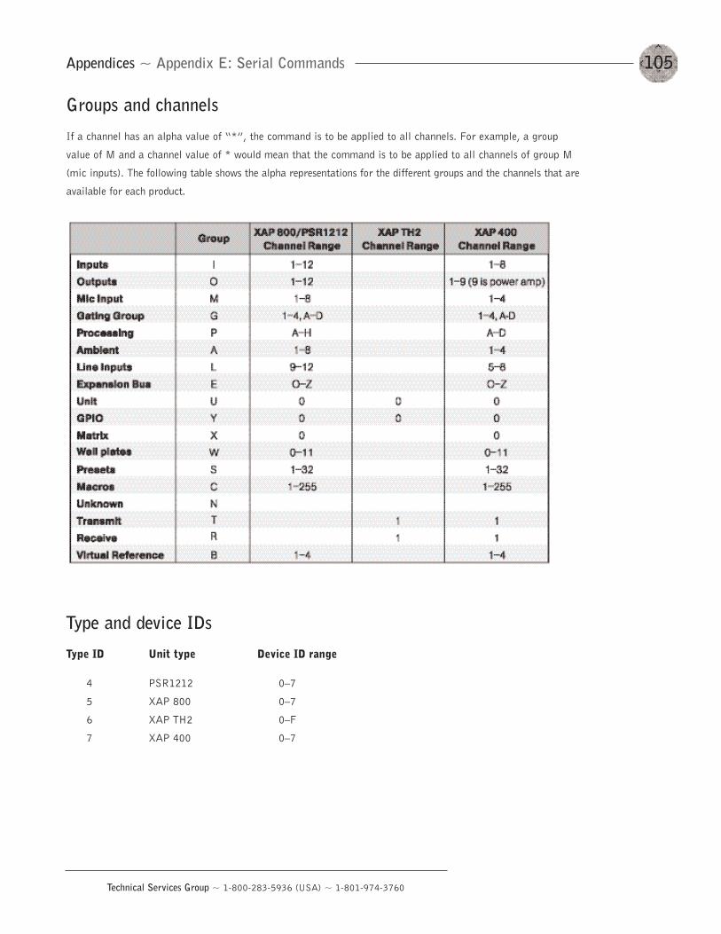
105
Technical Services Group ~ 1-800-283-5936 (USA) ~ 1-801-974-3760
Appendices ~ Appendix E: Serial Commands
Groups and channels
If a channel has an alpha value of “*”, the command is to be applied to all channels. For example, a group
value of M and a channel value of * would mean that the command is to be applied to all channels of group M
(mic inputs). The following table shows the alpha representations for the different groups and the channels that are
available for each product.
Type and device IDs
Type ID Unit type Device ID range
4 PSR1212 0—7
5 XAP 800 0—7
6 XAP TH2 0—F
7 XAP 400 0—7
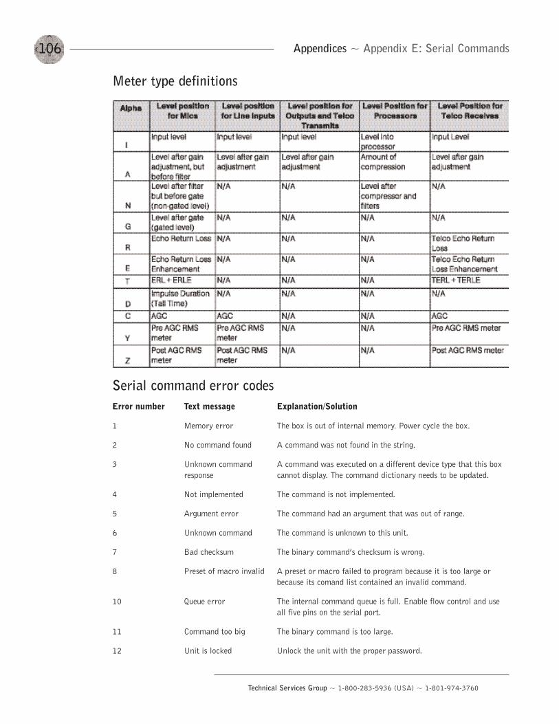
106
Technical Services Group ~ 1-800-283-5936 (USA) ~ 1-801-974-3760
Appendices ~ Appendix E: Serial Commands
Meter type definitions
Serial command error codesError number Text message Explanation/Solution
1 Memory error The box is out of internal memory. Power cycle the box.
2 No command found A command was not found in the string.
3 Unknown command A command was executed on a different device type that this boxresponse cannot display. The command dictionary needs to be updated.
4 Not implemented The command is not implemented.
5 Argument error The command had an argument that was out of range.
6 Unknown command The command is unknown to this unit.
7 Bad checksum The binary command’s checksum is wrong.
8 Preset of macro invalid A preset or macro failed to program because it is too large or because its comand list contained an invalid command.
10 Queue error The internal command queue is full. Enable flow control and use all five pins on the serial port.
11 Command too big The binary command is too large.
12 Unit is locked Unlock the unit with the proper password.
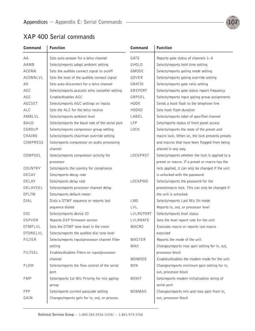
107
Technical Services Group ~ 1-800-283-5936 (USA) ~ 1-801-974-3760
XAP 400 Serial commands
Command Function
AA Sets auto-answer for a telco channel
AAMB Selects/reports adapt ambient setting
ACONN Sets the audible connect signal to on/off
ACONNLVL Sets the level of the audible connect signal
AD Sets auto-disconnect for a telco channel
AEC Selects/reports acoustic echo canceller setting
AGC Enable/disables AGC
AGCSET Selects/reports AGC settings on inputs
ALC Sets the ALC for the telco receive
AMBLVL Selects/reports ambient level
BAUD Selects/reports the baud rate of the serial port
CGROUP Selects/reports compressor group setting
CHAIRO Selects/reports chairman override setting
COMPRESS Sets/reports compressor on audio processing
channel
COMPSEL Selects/reports compressor activity for
processor
COUNTRY Sets/reports the country for compliance
DECAY Sets/reports decay rate
DELAY Sets/reports delay rate
DELAYSEL Selects/reports processor channel delay
DFLTM Sets/reports default meter
DIAL Dials a DTMF sequence or reports last
sequence dialed
DID Selects/reports device ID
DSPVER Reports DSP firmware version
DTMFLVL Sets the DTMF tone level in the room
DTONELVL Selects/reports the audible dial tone level
FILTER Selects/reports input/processor channel filter
setting
FILTSEL Enables/disables filters on input/processor
channel
FLOW Selects/reports the flow control of the serial
port
FMP Sets/reports 1st Mic Priority for mic gating
group
FPP Sets/reports current passcode setting
GAIN Changes/reports gain for in, out, or process.
Command Function
GATE Reports gate status of channels 1—4
GHOLD Selects/reports hold time setting
GMODE Selects/reports gating mode setting
GOVER Selects/reports gating override setting
GRATIO Selects/reports gate ratio setting
GREPORT Selects/reports gate status report frequency
GRPSEL Selects/reports input gating group assignments
HOOK Sends a hook flash to the telephone line
HOOKD Sets hook flash duration
LABEL Selects/reports label of specified channel
LFP Sets/reports status of front panel access
LOCK Selects/reports the state of the preset and
macro lock. When on, the lock prevents presets
and macros that have been flagged from being
altered in any way.
LOCKPRST Selects/reports whether the lock is applied to a
preset or macro. If a preset or macro has the
lock applied, it can only be changed if the unit
is unlocked with the password.
LOCKPWD Selects/reports the password for the
preset/macro lock. This can only be changed if
the unit is unlocked.
LMO Selects/reports Last Mic On mode
LVL Reports in, out, or processor level
LVLREPORT Selects/reports level status
LVLRRATE Sets the level report rate for the unit
MACRO Executes macro or reports last macro
executed
MASTER Reports the mode of the unit
MAX Changes/reports max gain setting for in, out,
processor block
MDMODE Enables/disables the modem mode for the unit
MIN Changes/reports minimum gain setting for in,
out, processor block
MINIT Sets/reports modem initialization string of
serial port
MINMAX Changes/reports min and max gain from in,
out, processor block
Appendices ~ Appendix E: Serial Commands
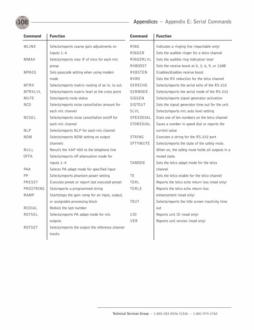
108
Technical Services Group ~ 1-800-283-5936 (USA) ~ 1-801-974-3760
Appendices ~ Appendix E: Serial Commands
Command Function
MLINE Selects/reports coarse gain adjustments on
Inputs 1—4
MMAX Selects/reports max # of mics for each mic
group
MPASS Sets passcode setting when using modem
mode
MTRX Selects/reports matrix routing of an in. to out.
MTRXLVL Selects/reports matrix level at the cross point
MUTE Sets/reports mute status
NCD Selects/reports noise cancellation amount for
each mic channel
NCSEL Selects/reports noise cancellation on/off for
each mic channel
NLP Selects/reports NLP for each mic channel
NOM Selects/reports NOM setting on output
channels
NULL Renulls the XAP 400 to the telephone line
OFFA Selects/reports off attenuation mode for
inputs 1—4
PAA Selects PA adapt mode for specified input
PP Selects/reports phantom power setting
PRESET Executes preset or report last executed preset
PRGSTRING Sets/reports a programmed string
RAMP Start/stops the gain ramp for an input, output,
or assignable processing block
REDIAL Redials the last number
REFSEL Selects/reports PA adapt mode for mic
outputs
REFSET Selects/reports the output the reference channel
tracks
Command Function
RING Indicates a ringing line (reportable only)
RINGER Sets the audible ringer for a telco channel
RINGERLVL Sets the audible ring indication level
RXBOOST Sets the receive boost at 0, 3, 6, 9, or 12dB
RXBSTEN Enables/disables receive boost
RXRD Sets the RX reduction for the telco channel
SERECHO Selects/reports the serial echo of the RS-232
SERMODE Selects/reports the serial mode of the RS-232
SIGGEN Selects/reports signal generator activation
SIGTOUT Sets the signal generator time out for the unit
SLVL Selects/reports mic auto level setting
SPEEDDIAL Dials one of ten numbers on the telco channel
STOREDIAL Saves a number in speed dial or reports the
current value
STRING Executes a string for the RS-232 port
SFTYMUTE Selects/reports the state of the safety mute.
When on, the safety mute holds all outputs in a
muted state.
TAMODE Sets the telco adapt mode for the telco
channel
TE Sets the telco enable for the telco channel
TERL Reports the telco echo return loss (read only)
TERLE Reports the telco echo return loss
enhancement (read only)
TOUT Selects/reports the title screen inactivity time
out
UID Reports unit ID (read only)
VER Reports unit version (read only)
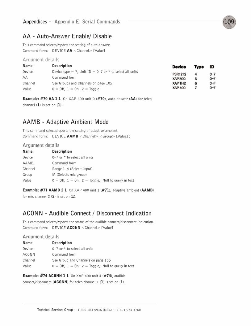
109
Technical Services Group ~ 1-800-283-5936 (USA) ~ 1-801-974-3760
Appendices ~ Appendix E: Serial Commands
AA - Auto-Answer Enable/ DisableThis command selects/reports the setting of auto-answer.Command form: DEVICE AA <Channel> [Value]
Argument detailsName DescriptionDevice Device type = 7, Unit ID = 0—7 or * to select all unitsAA Command formChannel See Groups and Channels on page 105Value 0 = Off, 1 = On, 2 = Toggle
Example: #70 AA 1 1 On XAP 400 unit 0 (#70), auto-answer (AA) for telco
channel (1) is set on (1).
AAMB - Adaptive Ambient ModeThis command selects/reports the setting of adaptive ambient.Command form: DEVICE AAMB <Channel> <Group> [Value] :
Argument detailsName DescriptionDevice 0—7 or * to select all unitsAAMB Command formChannel Range 1—4 (Selects input)Group M (Selects mic group)Value 0 = Off, 1 = On, 2 = Toggle, Null to query in text
Example: #71 AAMB 2 1 On XAP 400 unit 1 (#71), adaptive ambient (AAMB)
for mic channel 2 (2) is set on (1).
ACONN - Audible Connect / Disconnect IndicationThis command selects/reports the status of the audible connect/disconnect indication.Command form: DEVICE ACONN <Channel> [Value]
Argument detailsName DescriptionDevice 0—7 or * to select all unitsACONN Command formChannel See Group and Channels on page 105Value 0 = Off, 1 = On, 2 = Toggle, Null to query in text
Example: #74 ACONN 1 1 On XAP 400 unit 4 (#74), audible
connect/disconnect (ACONN) for telco channel 1 (1) is set on (1).
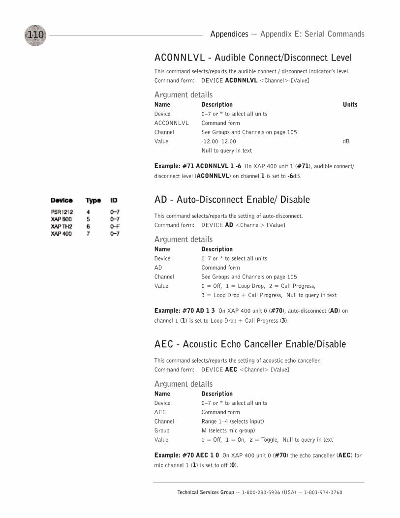
110
Technical Services Group ~ 1-800-283-5936 (USA) ~ 1-801-974-3760
Appendices ~ Appendix E: Serial Commands
ACONNLVL - Audible Connect/Disconnect LevelThis command selects/reports the audible connect / disconnect indicator’s level.Command form: DEVICE ACONNLVL <Channel> [Value]
Argument detailsName Description UnitsDevice 0—7 or * to select all unitsACCONNLVL Command formChannel See Groups and Channels on page 105Value -12.00—12.00 dB
Null to query in text
Example: #71 ACONNLVL 1 -6 On XAP 400 unit 1 (#71), audible connect/
disconnect level (ACONNLVL) on channel 1 is set to -6dB.
AD - Auto-Disconnect Enable/ DisableThis command selects/reports the setting of auto-disconnect. Command form: DEVICE AD <Channel> [Value]
Argument detailsName DescriptionDevice 0—7 or * to select all unitsAD Command formChannel See Groups and Channels on page 105Value 0 = Off, 1 = Loop Drop, 2 = Call Progress,
3 = Loop Drop + Call Progress, Null to query in text
Example: #70 AD 1 3 On XAP 400 unit 0 (#70), auto-disconnect (AD) on
channel 1 (1) is set to Loop Drop + Call Progress (3).
AEC - Acoustic Echo Canceller Enable/DisableThis command selects/reports the setting of acoustic echo canceller.Command form: DEVICE AEC <Channel> [Value]
Argument detailsName DescriptionDevice 0—7 or * to select all unitsAEC Command formChannel Range 1—4 (selects input)Group M (selects mic group)Value 0 = Off, 1 = On, 2 = Toggle, Null to query in text
Example: #70 AEC 1 0 On XAP 400 unit 0 (#70) the echo canceller (AEC) for
mic channel 1 (1) is set to off (0).
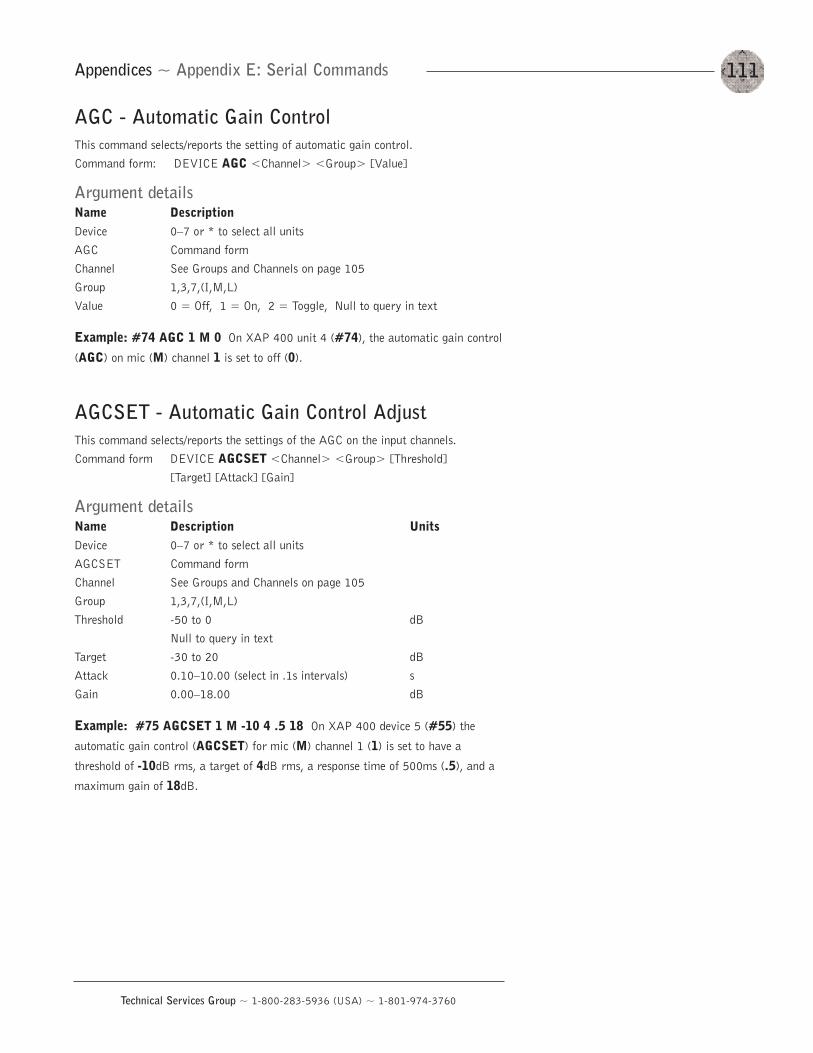
111
Technical Services Group ~ 1-800-283-5936 (USA) ~ 1-801-974-3760
Appendices ~ Appendix E: Serial Commands
AGC - Automatic Gain ControlThis command selects/reports the setting of automatic gain control.Command form: DEVICE AGC <Channel> <Group> [Value]
Argument detailsName DescriptionDevice 0—7 or * to select all unitsAGC Command formChannel See Groups and Channels on page 105Group 1,3,7,(I,M,L)Value 0 = Off, 1 = On, 2 = Toggle, Null to query in text
Example: #74 AGC 1 M 0 On XAP 400 unit 4 (#74), the automatic gain control
(AGC) on mic (M) channel 1 is set to off (0).
AGCSET - Automatic Gain Control AdjustThis command selects/reports the settings of the AGC on the input channels.Command form DEVICE AGCSET <Channel> <Group> [Threshold]
[Target] [Attack] [Gain]
Argument detailsName Description UnitsDevice 0—7 or * to select all unitsAGCSET Command formChannel See Groups and Channels on page 105Group 1,3,7,(I,M,L)Threshold -50 to 0 dB
Null to query in textTarget -30 to 20 dBAttack 0.10—10.00 (select in .1s intervals) sGain 0.00—18.00 dB
Example: #75 AGCSET 1 M -10 4 .5 18 On XAP 400 device 5 (#55) the
automatic gain control (AGCSET) for mic (M) channel 1 (1) is set to have a
threshold of -10dB rms, a target of 4dB rms, a response time of 500ms (.5), and a
maximum gain of 18dB.
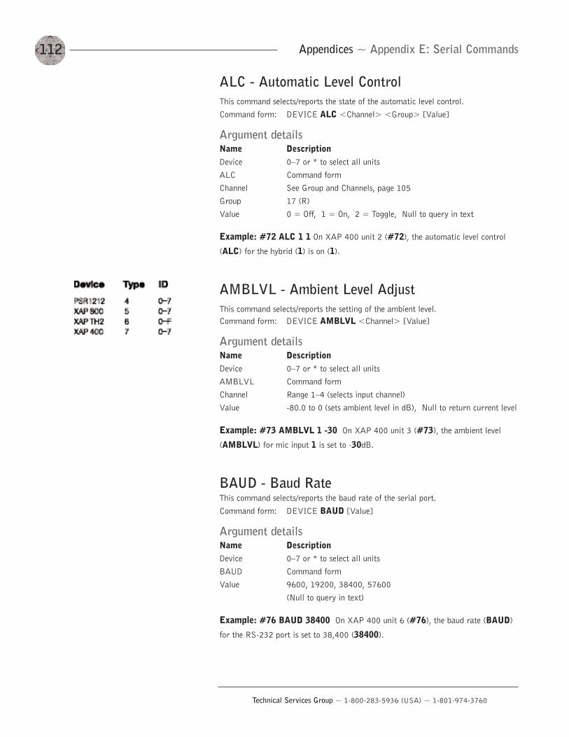
112
Technical Services Group ~ 1-800-283-5936 (USA) ~ 1-801-974-3760
Appendices ~ Appendix E: Serial Commands
ALC - Automatic Level ControlThis command selects/reports the state of the automatic level control.Command form: DEVICE ALC <Channel> <Group> [Value]
Argument detailsName DescriptionDevice 0—7 or * to select all unitsALC Command formChannel See Group and Channels, page 105Group 17 (R)Value 0 = Off, 1 = On, 2 = Toggle, Null to query in text
Example: #72 ALC 1 1 On XAP 400 unit 2 (#72), the automatic level control
(ALC) for the hybrid (1) is on (1).
AMBLVL - Ambient Level AdjustThis command selects/reports the setting of the ambient level.Command form: DEVICE AMBLVL <Channel> [Value]
Argument detailsName DescriptionDevice 0—7 or * to select all unitsAMBLVL Command formChannel Range 1—4 (selects input channel)Value -80.0 to 0 (sets ambient level in dB), Null to return current level
Example: #73 AMBLVL 1 -30 On XAP 400 unit 3 (#73), the ambient level
(AMBLVL) for mic input 1 is set to -30dB.
BAUD - Baud RateThis command selects/reports the baud rate of the serial port.Command form: DEVICE BAUD [Value]
Argument detailsName DescriptionDevice 0—7 or * to select all unitsBAUD Command formValue 9600, 19200, 38400, 57600
(Null to query in text)
Example: #76 BAUD 38400 On XAP 400 unit 6 (#76), the baud rate (BAUD)
for the RS-232 port is set to 38,400 (38400).

113
Technical Services Group ~ 1-800-283-5936 (USA) ~ 1-801-974-3760
Appendices ~ Appendix E: Serial Commands
CGROUP - Compressor Group SelectThis command selects/reports the setting of the compressor group on each assignableprocessing channel.Command form: DEVICE CGROUP <Channel> [Value]
Argument detailsName DescriptionDevice 0—7 or * to select all unitsCGROUP Command formChannel range A—D (selects processing channel)Value 0 = none, 1 = compressor group 1, 2 = compressor group 2,
3 = compressor group 3, 4 = compressor group 4,null to return the current mode
Example: #72 CGROUP A 2 On XAP 400 unit 2 (#72), the compression group
(CGROUP) for processing channel A is 2.
CHAIRO - Chairman Override Mode
This command selects/reports the setting of chairman override.
Command form: DEVICE CHAIRO <Channel> [Value]
Argument detailsName DescriptionDevice 0—7 or * to select all unitsCHAIRO Command formChannel Range 1—4 (selects mic input)Value 0 = Off, 1 = On, 2 = Toggle, Null to return current state
Example: #77 CHAIRO 3 1 On XAP 400 unit 7 (#77), chairman override
(CHAIRO) for mic channel 3 is set on (1).
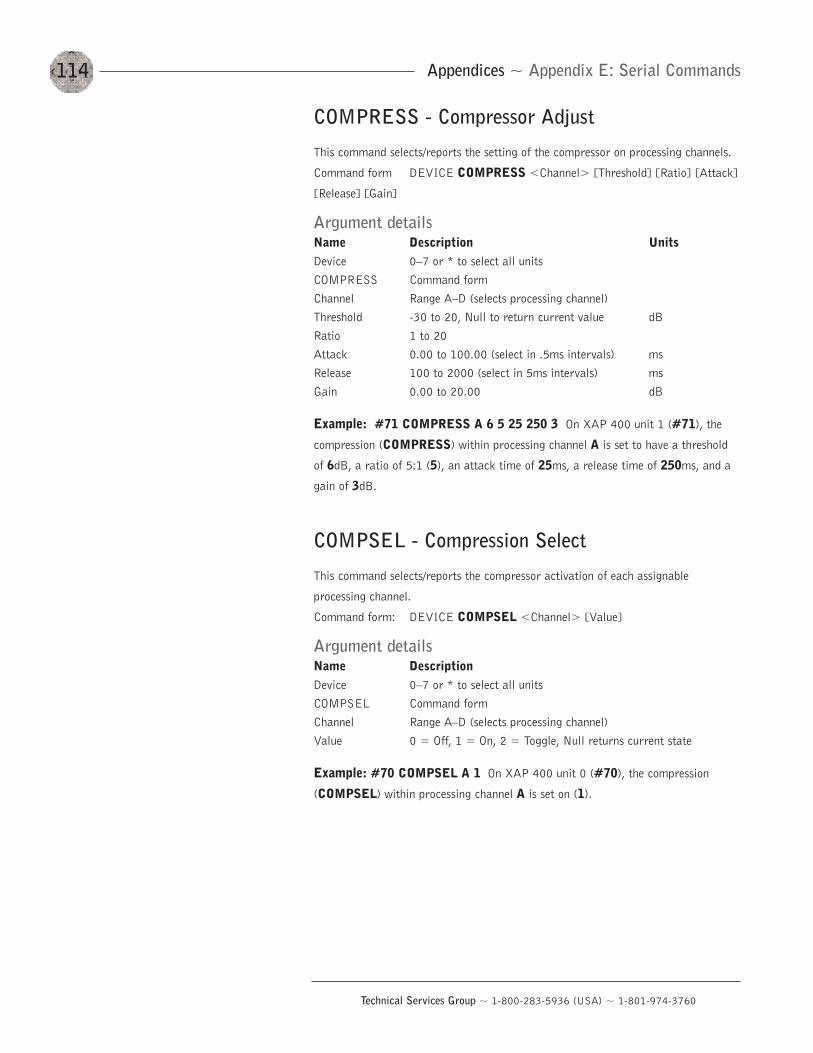
114
Technical Services Group ~ 1-800-283-5936 (USA) ~ 1-801-974-3760
Appendices ~ Appendix E: Serial Commands
COMPRESS - Compressor Adjust
This command selects/reports the setting of the compressor on processing channels.
Command form DEVICE COMPRESS <Channel> [Threshold] [Ratio] [Attack]
[Release] [Gain]
Argument detailsName Description UnitsDevice 0—7 or * to select all unitsCOMPRESS Command formChannel Range A—D (selects processing channel)Threshold -30 to 20, Null to return current value dBRatio 1 to 20Attack 0.00 to 100.00 (select in .5ms intervals) msRelease 100 to 2000 (select in 5ms intervals) msGain 0.00 to 20.00 dB
Example: #71 COMPRESS A 6 5 25 250 3 On XAP 400 unit 1 (#71), the
compression (COMPRESS) within processing channel A is set to have a threshold
of 6dB, a ratio of 5:1 (5), an attack time of 25ms, a release time of 250ms, and a
gain of 3dB.
COMPSEL - Compression Select
This command selects/reports the compressor activation of each assignable
processing channel.
Command form: DEVICE COMPSEL <Channel> [Value]
Argument detailsName DescriptionDevice 0—7 or * to select all unitsCOMPSEL Command formChannel Range A—D (selects processing channel)Value 0 = Off, 1 = On, 2 = Toggle, Null returns current state
Example: #70 COMPSEL A 1 On XAP 400 unit 0 (#70), the compression
(COMPSEL) within processing channel A is set on (1).
115
Technical Services Group ~ 1-800-283-5936 (USA) ~ 1-801-974-3760
Appendices ~ Appendix E: Serial Commands
COUNTRY — Country SelectionThis command sets/reports the country for compliance.Command form: DEVICE COUNTRY [Value]
Argument detailsName DescriptionDevice 0—7 or * to select all unitsCOUNTRY Command formValue 1 = US/Canada, 2 = Europe (CTR21), 3 = Mexico
4 = Australia, 5 = South Africa, 6 = Japan7 = Brazil, Null to return current state
Example: #70 COUNTRY 1 On the XAP 400 unit 0 (#70), the country selection
(COUNTRY) is set to US/Canada (1).
DECAY - Decay Adjust
This command selects/reports the setting of the decay rate for a specified input.
Command form: DEVICE DECAY <Channel> [Value]
Argument detailsName DescriptionDevice 0—7 or * to select all unitsDECAY Command formChannel Range 1—4 (selects mic input)Value 1 = Slow, 2 = Medium, 3 = Fast, Null to return current state
Example: #73 DECAY 1 3 On XAP 400 unit 3 (#73), the decay rate (DECAY)
for mic channel 1 is set to fast (3).
DELAY - Delay Adjust
This command selects/reports the delay time of each assignable processing channel.
Command form: DEVICE DELAY <Channel> [Value]
Argument detailsName Description UnitsDevice 0—7 or * to select all unitsDELAY Command formChannel A—D (select processing channel)Value 0.00 to 250 (selects delay) ms
Null to return current state
Example: #76 DELAY A 200 On XAP 400 unit 6 (#76) the delay (DELAY) for
processing channel A is set to 200ms.
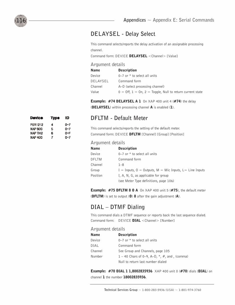
116
Technical Services Group ~ 1-800-283-5936 (USA) ~ 1-801-974-3760
Appendices ~ Appendix E: Serial Commands
DELAYSEL - Delay Select
This command selects/reports the delay activation of an assignable processing
channel.
Command form: DEVICE DELAYSEL <Channel> [Value]
Argument detailsName DescriptionDevice 0—7 or * to select all unitsDELAYSEL Command formChannel A—D (select processing channel)Value 0 = Off, 1 = On, 2 = Toggle, Null to return current state
Example: #74 DELAYSEL A 1 On XAP 400 unit 4 (#74) the delay
(DELAYSEL) within processing channel A is enabled (1).
DFLTM - Default Meter
This command selects/reports the setting of the default meter.
Command form: DEVICE DFLTM [Channel] [Group] [Position]
Argument detailsName DescriptionDevice 0—7 or * to select all unitsDFLTM Command formChannel 1—8Group I = Inputs, O = Outputs, M = Mic Inputs, L= Line InputsPosition I, A, N, G, as applicable for group
(see Meter Type definitions, page 106)
Example: #75 DFLTM 8 O A On XAP 400 unit 5 (#75), the default meter
(DFLTM) is set to output (O) 8 after the gain adjustment (A).
DIAL — DTMF DialingThis command dials a DTMF sequence or reports back the last sequence dialed.Command form: DEVICE DIAL <Channel> [Number]
Argument detailsName DescriptionDevice 0—7 or * to select all unitsDIAL Command formChannel See Group and Channels, page 105Number 1 — 40 Chars of 0—9, A—D, *, #, and , (comma)
Null to return last number dialed
Example: #70 DIAL 1 1,8002835936 XAP 400 unit 0 (#70) dials (DIAL) on
channel 1 the number 18002835936.
117
Technical Services Group ~ 1-800-283-5936 (USA) ~ 1-801-974-3760
Appendices ~ Appendix E: Serial Commands
DID - Device ID
This command selects/reports the device ID.
Command form: DEVICE DID [Value]
Argument detailsName DescriptionDevice 0—7 or * to select all unitsDID Command formValue 0—7 (select device ID)
Example: #77 DID 0 On XAP 400 unit 7 (#77), the device ID (DID) is set to 0.
DSPVER - DSP Version
This command reports the version of the DSP code in the unit. the version is a date
and time stamp. This command is read only.
Command form: DEVICE DSPVER [value]
Argument detailsName DescriptionDevice 0—7 or * to select all unitsDSPVER Command formValue Null
Example: #75 DSPVER The XAP 400 unit 5 (#75) will return the DSP version
(DSPVER).
DTMFLVL - DTMF Tone LevelThis command selects/reports the DTMF tone’s level.Command form: DEVICE DTMFLVL <Channel> [Value]
Argument detailsName Description UnitsDevice 0—7 or * to select all unitsDTMFLVL Command formChannel See Group and Channels, page 105Value -12.00 to 12.00 dB
Null to return current state
Example: #72 DTMFLVL 1 6 On XAP 400 unit 2 (#72), the DTMF tone level
(DTMFLVL) is set to 6dB.
118
Technical Services Group ~ 1-800-283-5936 (USA) ~ 1-801-974-3760
Appendices ~ Appendix E: Serial Commands
DTONELVL - Dial Tone LevelThis command selects/reports the dial tone level.Command form: DEVICE DTONELVL <Channel> [Value]
Argument detailsName Description UnitsDevice 0—7 or * to select all unitsDTONELVL Command formChannel See Group and Channels, page 105Value -12.00 to 12.00 dB
Null to return current state
Example: #72 DTONELVL 1 3 On XAP 400 unit 2 (#72), the dial tone level
(DTONELVL) is set to 3dB.
FILTER - Filter Adjust
This command selects/reports the setting of filters.
Command form: DEVICE FILTER <Channel> <Group> <Node> [Type]
[Frequency] [Gain] [Bandwidth]
Argument detailsName DescriptionDevice 0—7 or * to select all unitsFILTER Command formChannel See Groups and Channels, page 105Group See Groups and Channels, page 105Node 1—4 (selects mic input filter)
1—15 (selects processing channel filter)Name Description UnitsType 0 = None, 1 = All Pass, 2 = Low Pass,
3 = High Pass, 4 = Low Shelving, 5 = High Shelving, 6 = Parametric Equalizer,7 = CD Horn, 8 = Bessel Crossover,9 = Butterworth Crossover,10 = Linkwitz-Riley Crossover, 11 = Notch,Null to return the current mode
Frequency 0 for Null (Type 0) Hz20 to 20,000 (Type 1—6, 8—11) Hz500 to 5,000 (Type 7) Hz
Gain 0 for Null (Type 0—3, 7, 11) dB-15.00 to 15.00 (Type 4—6) dB per octave12, 18, 24 (Type 8—9) dB per octave12, 24 (Type 10) dB per octave-80 nonadjustable (Type 11)
Bandwidth 0 to Null (Type 0—5, 7).05—5.00 (Type 6, 11)2 = low pass, 3 = high pass (Type 8—10)
119
Technical Services Group ~ 1-800-283-5936 (USA) ~ 1-801-974-3760
Appendices ~ Appendix E: Serial Commands
Examples
#70 FILTER 1 M 3 2 200 On XAP 400 unit 0 (#70) the filter (FILTER) for mic
(M) channel 1, node 3 is set as a low-pass filter (2) at 200Hz.
#71 FILTER B P 2 4 3000 -10 On XAP 400 unit 1 (#71) the filter (FILTER) for
processing (P) channel B, node 2, is set as a low shelving (4) filter at 3000Hz and a
gain of -10dB.
#72 FILTER 3 M 2 6 5000 -15 1.00 On XAP 400 unit 2 (#72), the filter
(FILTER) for mic (M) channel 3, node 2, is set as a PEQ (6) with a center frequency
of 5000Hz, a bandwidth of 1.00, and a gain of -15dB.
#73 FILTER B P 2 7 4000 On XAP 400 unit 3 (#73), the filter (FILTER) for
processing (P) channel B, node 2, is set as a CD Horn (7) at a frequency of 4000Hz.
FILTSEL - Filter Select
This command turns on and off the filters on input and audio processing channels.
Command form: DEVICE FILTSEL <Channel> <Group> <Node> [Value]
Argument detailsName DescriptionDevice 0—7 or * to select all unitsFILTSEL Command formChannel See Groups and Channels, page 105Group M = Mic Inputs, P = Processing ChannelsNode 1-4, or * for all (selects mic input filter)
1-15, or * for all (selects processing channel filter)Value 0 = Off, 1 = On, 2 = Toggle, Null to return current state
Example: #74 FILTSEL B P 2 1 On XAP 400 unit 4 (#74), the filter
(FILTSEL) on processing (P) channel B, node 2, is set to on (1).
FLOW - Flow ControlThis command selects/reports the flow control of the serial port on the unit. Hardware flow control is implemented using DTR and DSR. Command form: DEVICE FLOW [Value]
Argument detailsName DescriptionDevice 0—7 or * to select all unitsFLOW Command formValue 0 = Off, 1 = On, 2 = Toggle, Null to return current state
Example: #76 FLOW 1 On XAP 400 unit 6 (#76), the flow control (FLOW) to
the RS-232 port is set to on (1).
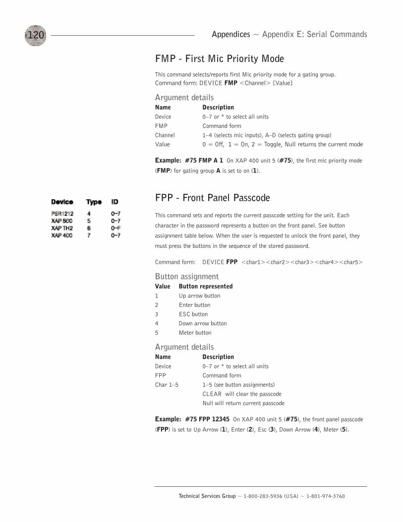
120
Technical Services Group ~ 1-800-283-5936 (USA) ~ 1-801-974-3760
Appendices ~ Appendix E: Serial Commands
FMP - First Mic Priority ModeThis command selects/reports first Mic priority mode for a gating group.Command form: DEVICE FMP <Channel> [Value]
Argument detailsName DescriptionDevice 0—7 or * to select all unitsFMP Command formChannel 1—4 (selects mic inputs), A—D (selects gating group)Value 0 = Off, 1 = On, 2 = Toggle, Null returns the current mode
Example: #75 FMP A 1 On XAP 400 unit 5 (#75), the first mic priority mode
(FMP) for gating group A is set to on (1).
FPP - Front Panel Passcode
This command sets and reports the current passcode setting for the unit. Each
character in the password represents a button on the front panel. See button
assignment table below. When the user is requested to unlock the front panel, they
must press the buttons in the sequence of the stored password.
Command form: DEVICE FPP <char1><char2><char3><char4><char5>
Button assignmentValue Button represented1 Up arrow button2 Enter button3 ESC button4 Down arrow button5 Meter button
Argument detailsName DescriptionDevice 0—7 or * to select all unitsFPP Command formChar 1—5 1—5 (see button assignments)
CLEAR will clear the passcodeNull will return current passcode
Example: #75 FPP 12345 On XAP 400 unit 5 (#75), the front panel passcode
(FPP) is set to Up Arrow (1), Enter (2), Esc (3), Down Arrow (4), Meter (5).
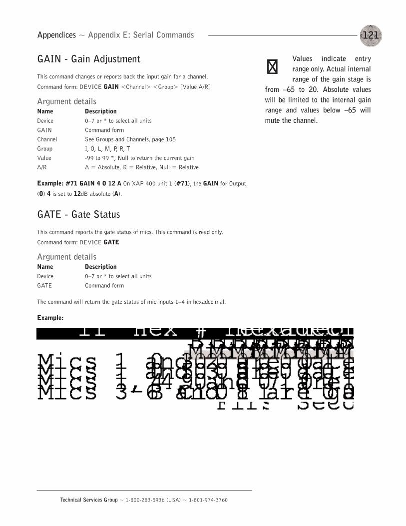
121
Technical Services Group ~ 1-800-283-5936 (USA) ~ 1-801-974-3760
Appendices ~ Appendix E: Serial Commands
GAIN - Gain Adjustment
This command changes or reports back the input gain for a channel.
Command form: DEVICE GAIN <Channel> <Group> [Value A/R]
Argument detailsName DescriptionDevice 0—7 or * to select all unitsGAIN Command formChannel See Groups and Channels, page 105Group I, O, L, M, P, R, TValue -99 to 99 *, Null to return the current gainA/R A = Absolute, R = Relative, Null = Relative
Example: #71 GAIN 4 O 12 A On XAP 400 unit 1 (#71), the GAIN for Output
(O) 4 is set to 12dB absolute (A).
GATE - Gate Status
This command reports the gate status of mics. This command is read only.
Command form: DEVICE GATE
Argument detailsName DescriptionDevice 0—7 or * to select all unitsGATE Command form
The command will return the gate status of mic inputs 1—4 in hexadecimal.
Example:
Values indicate entryrange only. Actual internalrange of the gain stage is
from —65 to 20. Absolute valueswill be limited to the internal gainrange and values below —65 willmute the channel.
��
122
Technical Services Group ~ 1-800-283-5936 (USA) ~ 1-801-974-3760
Appendices ~ Appendix E: Serial Commands
GHOLD- Gate Hold Time Adjust
This command selects/reports the setting of hold time.
Command form: DEVICE GHOLD <Channel> [Value]
Argument detailsName Description UnitsDevice 0—7 or * to select all unitsGHOLD Command formChannel See Groups and Channels, page 105Value 0.10-8.00 S
Null to return the current hold time
Example: #70 GHOLD 1 .3 On XAP 400 unit 0 (#70), the hold time (GHOLD)
for mic channel 1 is 300ms (.3).
GMODE - Gating Mode
This command selects/reports the setting of gating mode.
Command form: DEVICE GMODE <Channel> [Value]
Argument detailsName DescriptionDevice 0—7 or * to select all unitsGMODE Command formChannel 1—4 (select mic input)Value 1 = auto, 2 = manual on, 3 = manual off, Null= current mode
Example: #75 GMODE 1 2 On XAP 400 unit 5 (#75), mic channel 1 is set to a
gating mode (GMODE) if manual on (2).
GOVER - Gating Override
This command selects/reports the setting of gating override.
Command form: DEVICE GOVER <Channel> [Value]
Argument detailsName DescriptionDevice 0—7 or * to select all unitsGOVER Command formChannel 1—4 (select mic input)Value 0 = Off, 1 = On, 2 = Toggle, Null = current mode
Example: #76 GOVER 1 0 On XAP 400 unit 6 (#76), the gating override
(GOVER) on mic channel 1 is set to off (0).
123
Technical Services Group ~ 1-800-283-5936 (USA) ~ 1-801-974-3760
Appendices ~ Appendix E: Serial Commands
GRATIO - Gate Ratio Adjust
This command selects/reports the setting of the gate ratio.
Command form: DEVICE GRATIO <Channel> [Value]
Argument detailsName Description UnitsDevice 0—7 or * to select all unitsGRATIO Command formChannel 1—4 (select mic input)Value 0 to 50 dB
Null to return current ratio
Example: #72 GRATIO 1 15 On XAP 400 unit 2 (#72), the gate ratio
(GRATIO) for mic channel 1 is set to 15dB.
GREPORT - Gate Report
This command selects/reports the gate status.
Command form: DEVICE GREPORT <Value>
Argument detailsName DescriptionDevice 0—7 or * to select all unitsGREPORT Command formValue 0 = Off, 1 = On, 2 = Toggle
Example: #73 GREPORT 1 On XAP 400 unit 3 (#73), the gate reporting
(GREPORT) is set to on (1).
GRPSEL - Gating Group Select
This command selects/reports which gating group each input is assigned. There can
only be one selection per input.
Command form: DEVICE GRPSEL <Channel> [Value]
Argument detailsName DescriptionDevice 0—7 or * to select all unitsGRPSEL Command formChannel 1—4 (selects mic input)Value A—D (selects gating group), Null to return current value
Example: #74 GRPSEL 1 A On XAP 400 unit 4 (#74), mic channel 1 is
assigned to gating group (GRPSEL) A.
Gate report sends a reporton every gate change. If nomics are gated on, the
report will be sent every 10 seconds.
��
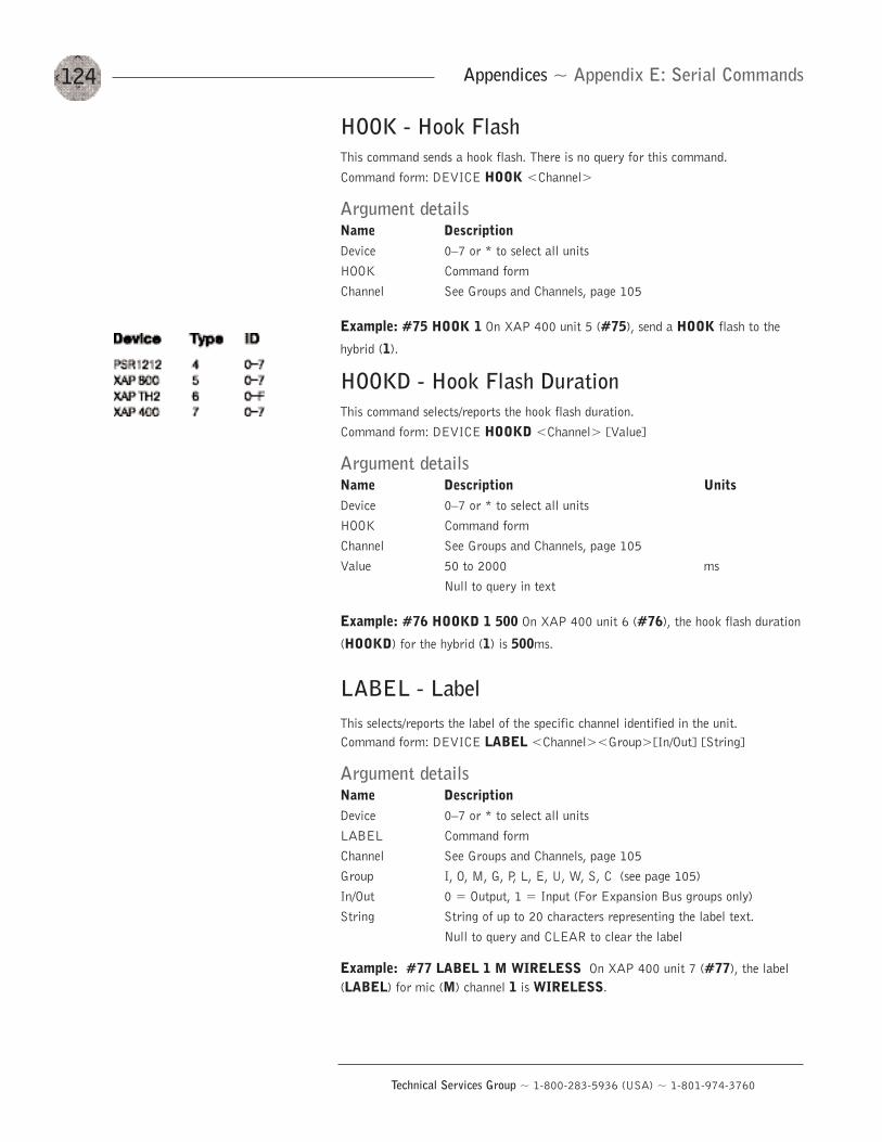
124
Technical Services Group ~ 1-800-283-5936 (USA) ~ 1-801-974-3760
Appendices ~ Appendix E: Serial Commands
HOOK - Hook FlashThis command sends a hook flash. There is no query for this command.Command form: DEVICE HOOK <Channel>
Argument detailsName DescriptionDevice 0—7 or * to select all unitsHOOK Command formChannel See Groups and Channels, page 105
Example: #75 HOOK 1 On XAP 400 unit 5 (#75), send a HOOK flash to the
hybrid (1).
HOOKD - Hook Flash DurationThis command selects/reports the hook flash duration.Command form: DEVICE HOOKD <Channel> [Value]
Argument detailsName Description UnitsDevice 0—7 or * to select all unitsHOOK Command formChannel See Groups and Channels, page 105Value 50 to 2000 ms
Null to query in text
Example: #76 HOOKD 1 500 On XAP 400 unit 6 (#76), the hook flash duration
(HOOKD) for the hybrid (1) is 500ms.
LABEL - LabelThis selects/reports the label of the specific channel identified in the unit.Command form: DEVICE LABEL <Channel><Group>[In/Out] [String]
Argument detailsName DescriptionDevice 0—7 or * to select all unitsLABEL Command formChannel See Groups and Channels, page 105Group I, O, M, G, P, L, E, U, W, S, C (see page 105)In/Out 0 = Output, 1 = Input (For Expansion Bus groups only)String String of up to 20 characters representing the label text.
Null to query and CLEAR to clear the label
Example: #77 LABEL 1 M WIRELESS On XAP 400 unit 7 (#77), the label(LABEL) for mic (M) channel 1 is WIRELESS.
125
Technical Services Group ~ 1-800-283-5936 (USA) ~ 1-801-974-3760
Appendices ~ Appendix E: Serial Commands
LFP - Lock Front PanelThis command sets and reports front panel access for the unit. When the unit islocked, access is not allowed to the unit until the unit is unlocked.Command form: DEVICE LFP [Value]
Argument detailsName DescriptionDevice 0—7 or * to select all unitsLFP Command formValue 0 = Unlock Panel, 1 = Lock Panel, 2 = Toggle Value,
3 = Lock when timed out
Example: #74 LFP 1 The XAP 400 unit 4 (#74), front panel (LFP) is locked (1).
LMO - Last Mic On ModeThis command selects/reports last Mic on mode for the specified gating group.Command form: DEVICE LMO <Channel> [Value]
Argument detailsName DescriptionDevice 0—7 or * to select all unitsLMO Command formChannel See Groups and Channels, page 105Value 0 = Last Mic Mode disabled
1—8 = Select Last Mic mode on specified channel * = Last mic to stay on, Null to return the current mode
Example: #70 LMO A 0 On XAP 400 unit 0 (#70), the Last Mic Mode (LMO)for gating group A is disabled (0).
LOCK - Preset and Macro LockThis command selects/reports the state of the preset and macro lock. When on, thelock prevents flagged presets and macros from being altered in any way.Command form: DEVICE LOCK [Value][Password]
Argument detailsName DescriptionDevice 0—7 or * to select all unitsLOCK Command formValue 0 = Off, 1 = On, 2 = TogglePassword Only needs to be entered when changing the lock. For security,
this value is not returned.
Example: #71 LOCK 1 “password” On XAP 400 unit 1 (#71), any presets ormacros that have been flagged with the LOCKPRST command will be locked(LOCK) and password protected (1) with the macro/preset password (LOCKPWD).
126
Technical Services Group ~ 1-800-283-5936 (USA) ~ 1-801-974-3760
Appendices ~ Appendix E: Serial Commands
LOCKPRST - Apply the lock to a preset or macroSelects/reports whether the lock is applied to a preset/macro. If a preset/macro hasthe lock applied, it can only be changed if unlocked with the password.Command form: DEVICE LOCKPRST <Channel><Group>[Value]
Argument detailsName DescriptionDevice 0—7 or * to select all unitsLOCKPRST Command formChannel 1—32 (Preset) or 1—255 (Macro)Group S = Preset, C = MacroValue 0 = Off, 1 = On, 2 = Toggle, Null = Query (value is only
returned if unit is unlocked)
Example: #72 LOCKPRST 5 S 1 On XAP 400 unit 2 (#72), preset 5 (5 S) willbe protected (1) whenever the lock option is enabled.
LOCKPWD - Set preset/macro passwordSelects/reports the password for the preset/macro lock. This can only be changed ifunit is unlocked.Command form: DEVICE LOCKPWD [Value]
Argument detailsName DescriptionDevice 0—7 or * to select all unitsLOCKPWD Command formValue 1—12 characters
Null = Query (value is only returned if unit is unlocked)
Example: #73 LOCKPWD mypassword On XAP 400 unit 3 (#73), themacro/preest password (LOCKPWD) is set to mypassword.
LVL - LevelThis command reports the level. This command is read only.Command form: DEVICE LVL <Channel> <Group> [Position] [Value]
Argument detailsName Description UnitsDevice 0—7 or * to select all unitsLVL Command formChannel See Groups and Channels, page 105Group See Groups and Channels, page 105Position See Meter Type Definitions, page 106Value -99.99 to 99.99 dB
Sent with Null in text, value returned
Example: #71 LVL 8 L I 3 The level (LVL) received from XAP 400 unit 1(#71) for line level (L) Input 8 at the Input stage (I) is 3dB.
127
Technical Services Group ~ 1-800-283-5936 (USA) ~ 1-801-974-3760
Appendices ~ Appendix E: Serial Commands
LVLREPORT - Level Report
This command selects level status reporting.
Command form: DEVICE LVLREPORT <Channel> <Group> [Position] [Value]
Argument detailsName DescriptionDevice 0—7 or * to select all unitsLVLREPORT Command formChannel See Groups and Channels, page 105Group See Groups and Channels, page 105Position See Meter Type Definitions, page 106Value 0 = Off (Delete level from list of levels to be reported)
1 =On (Add specified level to list of levels to be reported)2 = Toggle
Example: #72 LVLREPORT 8 L I 1 On XAP 400 unit 2 (#72), the level
(LVLREPORT) of line level (L) input 8 at the input stage (I) is to be added (1) to
the report.
LVLRRATE - Level Report Rate
Sets the level report rate for the unit and activates/deactivates level repeating.
Command form: DEVICE LVLRRATE [Value]
Argument detailsName Description UnitsDevice 0—7 or * to select all unitsLVLRRATE Command formValue 0 = Turn off reporting but leave current list
1 = Turn off reporting and clear the list50 to 1000 = Set Rate (1 meter every x ms) msNull to return current value
Example: #73 LVLRRATE 100 On XAP 400 unit 3 (#73), the level report rate
(LVLRRATE) is set to 100ms.
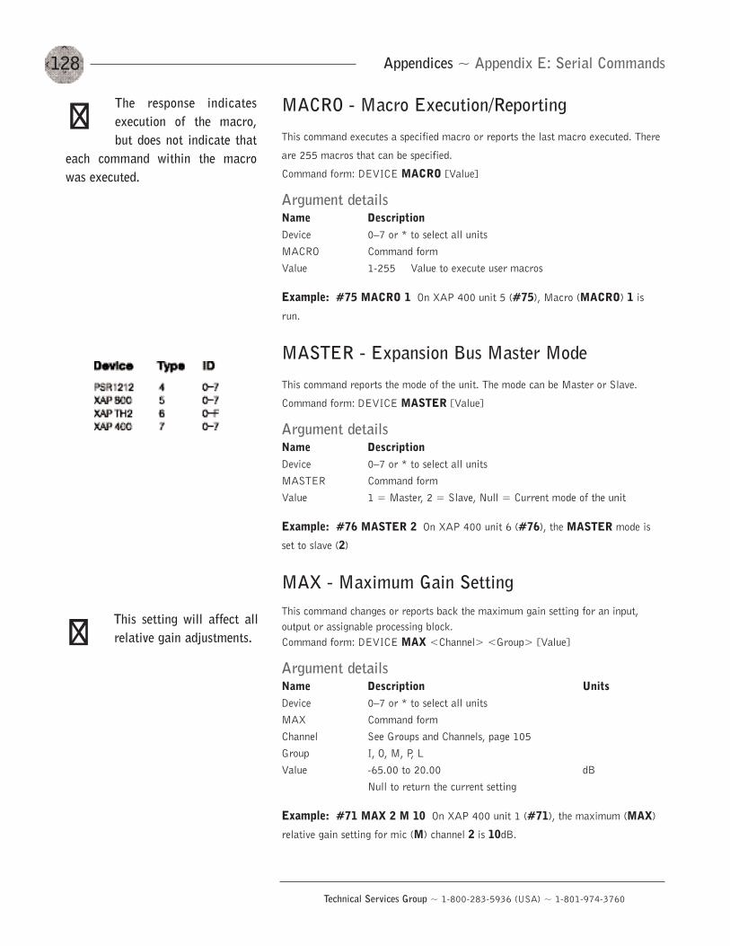
128
Technical Services Group ~ 1-800-283-5936 (USA) ~ 1-801-974-3760
Appendices ~ Appendix E: Serial Commands
MACRO - Macro Execution/Reporting
This command executes a specified macro or reports the last macro executed. There
are 255 macros that can be specified.
Command form: DEVICE MACRO [Value]
Argument detailsName DescriptionDevice 0—7 or * to select all unitsMACRO Command formValue 1-255 Value to execute user macros
Example: #75 MACRO 1 On XAP 400 unit 5 (#75), Macro (MACRO) 1 is
run.
MASTER - Expansion Bus Master Mode
This command reports the mode of the unit. The mode can be Master or Slave.
Command form: DEVICE MASTER [Value]
Argument detailsName DescriptionDevice 0—7 or * to select all unitsMASTER Command formValue 1 = Master, 2 = Slave, Null = Current mode of the unit
Example: #76 MASTER 2 On XAP 400 unit 6 (#76), the MASTER mode is
set to slave (2)
MAX - Maximum Gain SettingThis command changes or reports back the maximum gain setting for an input,output or assignable processing block.Command form: DEVICE MAX <Channel> <Group> [Value]
Argument detailsName Description UnitsDevice 0—7 or * to select all unitsMAX Command formChannel See Groups and Channels, page 105Group I, O, M, P, L Value -65.00 to 20.00 dB
Null to return the current setting
Example: #71 MAX 2 M 10 On XAP 400 unit 1 (#71), the maximum (MAX)
relative gain setting for mic (M) channel 2 is 10dB.
The response indicatesexecution of the macro,but does not indicate that
each command within the macrowas executed.
��
This setting will affect allrelative gain adjustments.��
129
Technical Services Group ~ 1-800-283-5936 (USA) ~ 1-801-974-3760
Appendices ~ Appendix E: Serial Commands
MDMODE - Modem ModeThis command enables or disables the modem mode for the unit. When the modemmode is enabled, the modem initialization string is sent out the serial port and theserial port now requires a password before a command is processed. After fiveminutes of serial inactivity the passcode will be requested to continue serial activity.
Command form: DEVICE MDMODE [Value]
Argument detailsName DescriptionDevice 0—7 or * to select all unitsMDMODE Command formValue 0 = Off, 1 = On, 2 = Toggle, Null = current modem mode state
Example: #77 MDMODE 1 On XAP 400 unit 7 (#77), the modem mode(MDMODE) is on (1).
MIN - Minimum Gain SettingThis command changes or reports back the minimum gain setting for an input, outputor assignable processing block.
Command form: DEVICE MIN <Channel> <Group> [Value]
Argument detailsName Description UnitsDevice 0—7 or * to select all unitsMIN Command formChannel See Groups and Channels, page 105Group I, O, M, P, L Value -65.00 to 20.00 dB
Null to return the current setting
Example: #74 MIN 2 M -10 On XAP 400 unit 4 (#74), the minimum (MIN)
relative gain setting for mic (M) channel 2 is -10dB.
130
Technical Services Group ~ 1-800-283-5936 (USA) ~ 1-801-974-3760
Appendices ~ Appendix E: Serial Commands
MINIT - Modem Initialization String
This command sets/reports the modem initialization string of the serial port when in
modem mode.
Command form: DEVICE MINIT [String]
Argument detailsName DescriptionDevice 0—7 or * to select all unitsMINIT Command formString 1-80 characters (select string characters to be sent to the modem
when the unit is initializedCLEAR = clears the modem initialization stringNull = Current string
Example: #76 MINIT ATZ On XAP 400 unit 6 (#76), the modem initialization
string (MINIT) is ATZ.
MINMAX - Minimum and Maximum Gain Setting
This command changes or reports back the minimum and maximum gain setting for
an input, output or assignable processing block.
Command form: DEVICE MINMAX <Channel> <Group> [Minimum] [Maximum]
Argument detailsName DescriptionDevice 0—7 or * to select all unitsMINMAX Command formChannel See Groups and ChannelsGroup I, O, M, P, LMinimum -65.00 to 20.00, Null to return current settingsMaximum -65.00 — 20.00
Example: #75 MINMAX 2 M -12 10 On XAP 400 unit 5 (#75), the minimum
and maximum (MINMAX) relative gain settings for mic (M) channel 2 are -12dB
and 10dB respectively.
131
Technical Services Group ~ 1-800-283-5936 (USA) ~ 1-801-974-3760
Appendices ~ Appendix E: Serial Commands
MLINE - Mic/Line AdjustThis command selects/reports the setting of coarse gain adjustment on the inputchannels 1-8. The three settings are 0dB, 25dB, and 55dB.Command form: DEVICE MLINE <Channel>[Value]
Argument detailsName DescriptionDevice 0—7 or * to select all unitsMLINE Command formChannel 1—4 (selects mic inputs)Value 0 = 0dB (line level), 1 = 55dB, 2 = 25dB, Null = current level
Example: #73 MLINE 1 2 On XAP 400 unit 3 (#73), the mic/line (MLINE)
setting for input 1 is 25dB (2).
MMAX - Maximum Number of MicrophonesThis command selects/reports the maximum number of microphones for each gatinggroup.Command form: DEVICE MMAX <Channel> [Value]
Argument detailsName DescriptionDevice 0—7 or * to select all unitsMMAX Command formChannel 1—4 (mic inputs), A-D (gating groups)Value 0 = Unlimited, 1—8 = Maximum number of mics
Null = Current maximum number of microphones
Example: #72 MMAX A 4 On the XAP 400 unit 2 (#72), the max number of
mics (MMAX) in gating group A that are allowed to gate on at any one time is 4.
MPASS - Modem PasswordThis command sets the current password setting for the unit when using modemmode. The password must be entered in twice.Command form: DEVICE MPASS [String]
Argument detailsName DescriptionDevice 0—7 or * to select all unitsMMAX Command formString 0-12 characters, CLEAR = to clear the current password
Null to report the current password
Example: #70 MPASS GENTNER On XAP 400 unit 0 (#70), the modem
password (MPASS) is set to GENTNER.
Once the command isgiven, the unit responds byechoing back the
command, followed by “RE-ENTER PASSWORD” string. Thecommand must then be re-enteredexactly as entered previously. Then,the command will be echoed back,followed by an “OK,” indicatingthat the password has beenchanged.
��
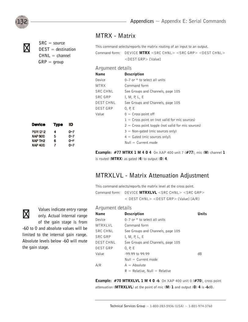
132
Technical Services Group ~ 1-800-283-5936 (USA) ~ 1-801-974-3760
Appendices ~ Appendix E: Serial Commands
MTRX - Matrix
This command selects/reports the matrix routing of an input to an output.
Command form: DEVICE MTRX <SRC CHNL> <SRC GRP> <DEST CHNL>
<DEST GRP> [Value]
Argument detailsName DescriptionDevice 0—7 or * to select all unitsMTRX Command formSRC CHNL See Groups and Channels, page 105SRC GRP I, M, P, L, EDEST CHNL See Groups and Channels, page 105DEST GRP O, P, EValue 0 = Cross point off
1 = Cross point on (not valid for mic sources)2 = Cross point toggle (not valid for mic sources)3 = Non-gated (mic sources only)4 = Gated (mic sources only)\Null = Current mode
Example: #77 MTRX 1 M 4 O 4 On XAP 400 unit 7 (#77), mic (M) channel 1
is routed (MTRX) as gated (4) to output (O) 4.
MTRXLVL - Matrix Attenuation Adjustment
This command selects/reports the matrix level at the cross point.
Command form: DEVICE MTRXLVL <SRC CHNL> <SRC GRP>
< DEST CHNL> <DEST GRP> [Value] [A/R]
Argument detailsName Description UnitsDevice 0—7 or * to select all unitsMTRXLVL Command formSRC CHNL See Groups and Channels, page 105SRC GRP I, M, P, L, EDEST CHNL See Groups and Channels, page 105DEST GRP O, P, EValue -99.99 to 99.99 dB
Null = Current modeA/R A = Absolute
R = Relative, Null = Relative
Example: #70 MTRXLVL 1 M 4 O -6 On XAP 400 unit 0 (#70), cross point
attenuation (MTRXLVL) at the point of mic (M) 1 and output (O) 4 is -6dB.
SRC = sourceDEST = destinationCHNL = channel GRP = group
��
Values indicate entry rangeonly. Actual internal rangeof the gain stage is from
-60 to 0 and absolute values will belimited to the internal gain range.Absolute levels below -60 will mutethe gain stage.
��
133
Technical Services Group ~ 1-800-283-5936 (USA) ~ 1-801-974-3760
Appendices ~ Appendix E: Serial Commands
MUTE - MuteSelects/reports the setting of mute on input, output or processing channels.Command form: DEVICE MUTE <Channel> <Group> [Value]
Argument detailsName DescriptionDevice 0—7 or * to select all unitsMUTE Command formChannel See Groups and Channels, page 105Group I, O, M, P, LValue 0 = Off, 1 = On, 2 = Toggle, Null = current mode
Example: #71 MUTE 2 M 1 On XAP 400 unit 1 (#71), the mute (MUTE) for
mic (M) channel 2 is on (1).
NCD - Noise Cancellation Depth
This command selects/reports the noise cancellation amount for each mic channel.
Command form: DEVICE NCD <Channel> <Group> [Value]
Argument detailsName DescriptionDevice 0—7 or * to select all unitsNCD Command formChannel 1—4 (select mic input) or 1 (telco receive)Group M or R Value 6 - 15 (set noise cancellation from 6 to 15dB),
Null to return the current mode
Example: #72 NCD 1 M 9 On XAP 400 unit 2 (#72), the noise cancellation
depth (NCD) of mic channel 1 (M) is 9dB.
NCSEL - Noise Cancellation SelectThis command selects/reports the Noise Cancellation for each mic channel.Command form: DEVICE NCSEL <Channel> <Group> <Value>
Argument detailsName DescriptionDevice 0—7 or * to select all unitsNCSEL Command formChannel 1—4 (select mic input) or 1 (telco receive)Group M or RValue 0 = Off, 1 = On, 2 = Toggle, Null = Current state
Example: #73 NCSEL 2 M 1 On XAP 400 unit 3 (#73), the noise cancellation(NCSEL) for mic channel 2 (M) is enabled (1).
Noise cancellation must beenabled for this commandto have any effect on audio
quality.
��
134
Technical Services Group ~ 1-800-283-5936 (USA) ~ 1-801-974-3760
Appendices ~ Appendix E: Serial Commands
NLP - Non-Linear Processing AdjustThis command selects/reports the setting of the Non-linear processing for eachmicrophone channel.Command form: DEVICE NLP <Channel> [Value]
Argument detailsName DescriptionDevice 0—7 or * to select all unitsNLP Command formChannel 1—4 (select mic input)Value 0 = Off, 1 = Soft, 2 = Medium, 3 = Aggressive
Null = Current mode
Example: #74 NLP 2 1 On XAP 400 unit 4 (#74), the non-linear processing
(NLP) for mic channel 2 is set to soft (1).
NOM - Number of Open Microphones Mode
This command selects/reports the setting of Number of Open Microphones (NOM) on
output channels.
Command form: DEVICE NOM <Channel> [Value]
Argument detailsName DescriptionDevice 0—7 or * to select all unitsNOM Command formChannel 1—9 (select output)Value 0 = Off, 1 = On, 2 = Toggle, Null = Current mode
Example: #75 NOM 2 1 On XAP 400 unit 5 (#75), the number of open
microphones (NOM) attenuation for output 2 is on (1).
NULL - Null the lineThis command nulls the line. There is no query for this command.Command form: DEVICE NULL <Channel>
Argument detailsName DescriptionDevice 0—7 or * to select all unitsNULL CommandChannel See Groups and Channels, page 105
Example: #76 NULL 1 On XAP 400 unit 6 (#76), the hybrid (1) will NULL the
phone line.
This setting is not affectedby the echo cancellersettings.
��
135
Technical Services Group ~ 1-800-283-5936 (USA) ~ 1-801-974-3760
Appendices ~ Appendix E: Serial Commands
OFFA - Off Attenuation Mode
This command selects/reports the off attenuation mode of input channels 1—4.
Command form: DEVICE OFFA <Channel> [Value]
Argument detailsName Description UnitsDevice 0—7 or * to select all unitsOFFA Command Channel 1—4 (select mic input)Value 0—60 (select off attenuation level) dB
Null to return the current off attenuation level
Example: #76 OFFA 1 12 On XAP 400 unit 6 (#76), the off attenuation
(OFFA) for mic channel 1 is 12dB.
PAA - PA Adaptive ModeThis command selects/reports PA adaptive mode for the specified mixer. There can beonly one selection per mixer.Command form: DEVICE PAA <Channel> [Value]
Argument detailsName Description UnitsDevice 0—7 or * to select all unitsPAA Command Channel 1—4 (select mic input)Value 0 = Off, 1 = On, 2 = Toggle, Null = Current mode
Example: #77 PAA 1 0 On XAP 400 unit 7 (#77), the PA adaptive mode (PAA)
on mic channel 1 is disabled (0).
PP - Phantom PowerThis command selects/reports the setting of phantom power.Command form: DEVICE PP <Channel> [Value]
Argument detailsName Description UnitsDevice 0—7 or * to select all unitsPP Command Channel 1—4 (select mic input)Value 0 = Off, 1 = On, 2 = Toggle, Null = Current mode
Example: #71 PP 2 1 On XAP 400 unit 1 (#71), the phantom power supply(PP) for mic channel 2 is enabled (1).
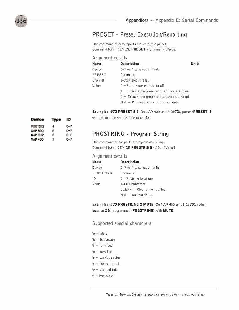
136
Technical Services Group ~ 1-800-283-5936 (USA) ~ 1-801-974-3760
Appendices ~ Appendix E: Serial Commands
PRESET - Preset Execution/ReportingThis command selects/reports the state of a preset.Command form: DEVICE PRESET <Channel> [Value]
Argument detailsName Description UnitsDevice 0—7 or * to select all unitsPRESET Command Channel 1—32 (select preset)Value 0 =Set the preset state to off
1 = Execute the preset and set the state to on2 = Execute the preset and set the state to offNull = Returns the current preset state
Example: #72 PRESET 5 1 On XAP 400 unit 2 (#72), preset (PRESET) 5
will execute and set the state to on (1).
PRGSTRING - Program StringThis command sets/reports a programmed string.Command form: DEVICE PRGSTRING <ID> [Value]
Argument detailsName DescriptionDevice 0—7 or * to select all unitsPRGSTRING Command ID 0 — 7 (string location)Value 1—80 Characters
CLEAR = Clear current valueNull = Current value
Example: #73 PRGSTRING 2 MUTE On XAP 400 unit 3 (#73), string
location 2 is programmed (PRGSTRING) with MUTE.
Supported special characters
\a = alert
\b = backspace
\f = formfeed
\n = new line
\r = carriage return
\t = horizontal tab
\v = vertical tab
\\ = backslash
137
Technical Services Group ~ 1-800-283-5936 (USA) ~ 1-801-974-3760
Appendices ~ Appendix E: Serial Commands
RAMP — Ramp Gain AdjustmentThis command starts/stops the gain ramp for an input, output, or assignable processing block. There is no query for this command.Command form: DEVICE RAMP <Channel><Group><Rate>[Target]
Argument detailsName Description UnitDevice 0—7 or * to select all unitsRAMP Command Channel See Groups and Channels, page 105Group I, O, M, L, P, T, R (1, 2, 3, 5, 16, 17)Rate -50 to 50 dB/s
If value = 0. the ramp will stopIf value < 0, the gain will ramp downIf value > 0, the gain will ramp up
Target -65 to 20 dBIf null in text, the ramp will use the channel’s maximum and minimum for a target
Example: #77 RAMP 5 L 6 12 On XAP 400 unit 7 (#77), the gain (RAMP)on Line Input 5 will increase at a rate of 6dB/sec until the 12dB point isreached.
REDIAL — Dial the last number againThis command redials the last number. There is no query for this command.Command form: DEVICE REDIAL <Channel>
Argument detailsName DescriptionDevice 0—7 or * to select all unitsREDIAL Command Channel See Groups and Channels, page 105
Example: #70 REDIAL 1 On XAP 400 unit 0 (#70), the hybrid (1) will
REDIAL the last phone number dialed.
138
Technical Services Group ~ 1-800-283-5936 (USA) ~ 1-801-974-3760
Appendices ~ Appendix E: Serial Commands
REFSEL - PA/AEC Reference SelectThis command selects/reports which output is used for each mic as a reference forpower amp adaptation mode and acoustic echo cancellation where applicable. Therecan be only one selection per mixer.Command form: DEVICE REFSEL <Channel> [Ref. Group] [Ref. Channel]
Argument detailsName DescriptionDevice 0—7 or * to select all unitsREFSEL Command Channel 1—4 (select mic input)Ref. Group 0 = Output, E = Expansion busRef. Channel 1—9, O—Z (select output or E-bus channel)
Example: #70 REFSEL 1 O 8 On XAP 400 unit 7 (#70), the PA/AEC
reference REFSEL for mic channel 1 is output (O) 12.
REFSET - Reference channel setupThis command selects/reports the output the reference channel tracks.Command form: DEVICE REFSET <Channel> <Group>[Value]
Argument detailsName DescriptionDevice 0—7 or * to select all unitsREFSET Command Channel 1—4 (select Virtual Reference number)Group 1—9 (select output channel to track) Value 0 = none
Example: #73 REFSET 2 4 On XAP 400 unit 3 (#73), virtual reference (2) will
track gain changes mde on output channel 4.
RING - Ring IndicationThis command indicates a ringing line. This command is reportable only. It cannotbe queried or set.Command form: DEVICE RING <Channel>
Argument detailsName DescriptionDevice 0—7 or * to select all unitsRING Command Channel See Groups and Channels, page 105
Example: #71 RING 1 On XAP 400 unit 1 (#71), the hybrid (1) will detect an
incoming RING.
139
Technical Services Group ~ 1-800-283-5936 (USA) ~ 1-801-974-3760
Appendices ~ Appendix E: Serial Commands
RINGER - Audible Ring SelectionThis command sends/reports the use of an audible ring.Command form: DEVICE RINGER <Channel> [Value]
Argument detailsName DescriptionDevice 0—7 or * to select all unitsRINGER Command Channel See Groups and Channels, page 105Value 0 = Off, 1 = On, 2 = Toggle, Null = Current state
Example: #72 RINGER 11 On XAP 400 unit 2 (#72), the audible RINGER
indication for the hybrid (1) is on (1).
RINGERLVL - Audible Ring LevelThis command selects/reports the audible ring level.Command form: DEVICE RINGERLVL <Channel> [Value]
Argument detailsName Description UnitsDevice 0—7 or * to select all unitsRINGERLVL Command Channel See Groups and Channels, page 105Value -12.00 — 12.00 dB
(Null to query in text)
Example: #73 RINGERLVL 13 On XAP 400 unit 3 (#73), the audible ringer
level (RINGERLVL) for the hybrid (1) is 3dB.
RXBOOST - Receive BoostThis command selects/reports the receive boost status.Command form: DEVICE RXBOOST <Channel> [Value]
Argument detailsName Description UnitsDevice 0—7 or * to select all unitsRXBOOST Command Channel See Groups and Channels, page 105Value 0, 3, 6, 9, 12 dB
Null to return current state
Example: #74 RXBOOST 1 6 On XAP 400 unit 4 (#74), the receive boost
(RXBOOST) of the hybrid (1) is set to 6dB.
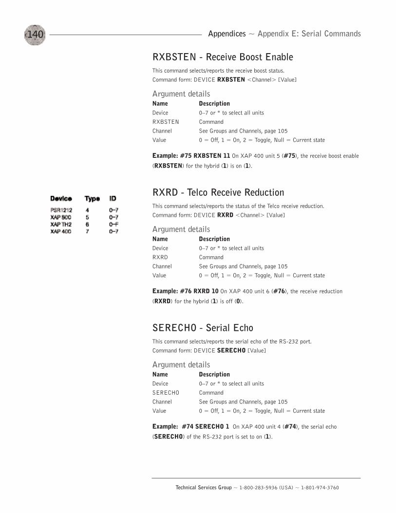
140
Technical Services Group ~ 1-800-283-5936 (USA) ~ 1-801-974-3760
Appendices ~ Appendix E: Serial Commands
RXBSTEN - Receive Boost EnableThis command selects/reports the receive boost status.Command form: DEVICE RXBSTEN <Channel> [Value]
Argument detailsName DescriptionDevice 0—7 or * to select all unitsRXBSTEN Command Channel See Groups and Channels, page 105Value 0 = Off, 1 = On, 2 = Toggle, Null = Current state
Example: #75 RXBSTEN 11 On XAP 400 unit 5 (#75), the receive boost enable
(RXBSTEN) for the hybrid (1) is on (1).
RXRD - Telco Receive ReductionThis command selects/reports the status of the Telco receive reduction.Command form: DEVICE RXRD <Channel> [Value]
Argument detailsName DescriptionDevice 0—7 or * to select all unitsRXRD Command Channel See Groups and Channels, page 105Value 0 = Off, 1 = On, 2 = Toggle, Null = Current state
Example: #76 RXRD 10 On XAP 400 unit 6 (#76), the receive reduction
(RXRD) for the hybrid (1) is off (0).
SERECHO - Serial EchoThis command selects/reports the serial echo of the RS-232 port.Command form: DEVICE SERECHO [Value]
Argument detailsName DescriptionDevice 0—7 or * to select all unitsSERECHO Command Channel See Groups and Channels, page 105Value 0 = Off, 1 = On, 2 = Toggle, Null = Current state
Example: #74 SERECHO 1 On XAP 400 unit 4 (#74), the serial echo
(SERECHO) of the RS-232 port is set to on (1).
141
Technical Services Group ~ 1-800-283-5936 (USA) ~ 1-801-974-3760
Appendices ~ Appendix E: Serial Commands
SERMODE - Serial ModeThis command selects/reports the serial mode of the RS-232 port.Command form: DEVICE SERMODE [Value]
Argument detailsName DescriptionDevice 0—7 or * to select all unitsSERMODE Command Value 1 = Text, 2 = Binary, Null = Current mode
Example: #75 SERMODE 1 On XAP 400 unit 5 (#75), the RS-232 port serial
mode (SERMODE) is set to text (1).
SFTYMUTE - Safety muteSelects/reports the state of the safety mute. When on, the safety mute holds all outputs on the selected unit in a muted state. It is used primarily for troubleshootingG-Ware.Command form: DEVICE SFTYMUTE [Value]
Argument detailsName DescriptionDevice 0—7 or * to select all unitsSFTYMUTE Command Value 0 = Off, 1 = On, 2 = Toggle, Null = Current state
Example: #72 SFTYMUTE 1 On XAP 400 unit 2 (#72), safety mute
(SFTYMUTE) is enabled (1).
SIGGEN - Signal GeneratorThis command selects/reports of the signal generator activation.Command form: DEVICE SIGGEN <Channel> <Group> [Type] [Amplitude]
[Frequency]
Argument detailsName DescriptionDevice 0—7 or * to select all unitsSIGGEN Command Channel See Groups and Channels, page 105Group I, M, LType 0 = Off, 1 = Pink, 2 = White, 3 = Tone, Null = Current stateAmplitude -60 to +20 amplitude in dB; NULL for type 0Frequency 20 to 20,000 frequency in Hz (only needed when using tone
generation)
Example: #76 SIGGEN 1 M 2 0 On XAP 400 unit 6 (#76), the signal gen-
erator (SIGGEN) is set to input at mic (M) channel 1 with white noise (2) at 0dB.
If the serial mode ischanged, the terminal willnot see a response from
the unit, nor will the unit respond tocommands until the new status ismatched by the terminal.
��
142
Technical Services Group ~ 1-800-283-5936 (USA) ~ 1-801-974-3760
Appendices ~ Appendix E: Serial Commands
SIGTOUT - Signal Generator Time OutSets the signal generator time out for the unit.Command form: DEVICE SIGTOUT [Value]
Argument detailsName DescriptionDevice 0—7 or * to select all unitsSIGGEN Command Value 0 = Off, 1—30 = Set time out minutes, Null = Current rate
Example: #57 SIGTOUT 15 On XAP 400 unit 7 (#77), the signal generator
time out (SIGTOUT) is set to 15 minutes.
SLVL - Speech Level Control Enable/Disable
This command selects/reports the setting of speech level control for a microphone.
Command form: DEVICE SLVL <Channel> [Value]
Argument detailsName DescriptionDevice 0—7 or * to select all unitsSLVL Command Channel 1—4 (select mic input)Value 0 = Off, 1 = On, 2 = Toggle, Null = Current mode
Example: #70 SLVL 2 M 1 On XAP 400 unit 0 (#70), the speech leveler for
mic (M) channel 2 is set to on (1).
SPEEDDIAL - Speed DialingThis command dials a speed dial number.Command form: DEVICE SPEEDDIAL <Channel> [Value]
Argument detailsName DescriptionDevice 0—7 or * to select all unitsSPEEDDIAL Command Channel See Groups and Channels, page 105Value 1 — 10, Null to query in text
Example: #71 SPEEDDIAL 15 On XAP 400 unit 1 (#71), SPEEDDIAL the
hybrid (1) with the number stored in location 5.

143
Technical Services Group ~ 1-800-283-5936 (USA) ~ 1-801-974-3760
Appendices ~ Appendix E: Serial Commands
STOREDIAL — Store a Number as a Speed DialThis command saves a number in a speed dial or reports the current value.Command form: DEVICE STOREDIAL <ID> [Number] [Label]
Argument detailsName DescriptionDevice 0—7 or * to select all unitsSTOREDIAL Command ID 1 — 10Number 1 — 40 chars 0—9, A—D, *, #
Null to query in textLabel 1—20 chars
Example: #72 STOREDIAL 5 1,8004478556 Express Conference On XAP
400 unit 2 (#72), store (STOREDIAL) the number 1,8004478556 and the name
of Express Conference into speed dial location 5.
STRING - String ExecutionThis command sends the specified string out the serial port.Command form: DEVICE STRING [ID]
Argument detailsName DescriptionDevice 0—7 or * to select all unitsSTRING Command ID 0 — 7
Null to query last string in text
Example: #71 STRING 3 On XAP 400 unit 1 (#71), the STRING programmed
into location 3 will be sent out the RS-232 port.
TAMODE - Telco Adapt ModeThis command selects/reports the Telco adapt mode.Command form: DEVICE TAMODE <Channel> [Value]
Argument detailsName DescriptionDevice 0—7 or * to select all unitsTAMODE Command Channel See Groups and Channels, page 105Value 0 = Auto, 1 = Burst, Null= Current mode
Example: #72 TAMODE 10 On XAP 400 unit 2 (#72), set the telco adaptmode (TAMODE) for the hybrid (1) to Auto (0).
The serial command tocreate a string isPRGSTRING (Program
String). See page 136.
��
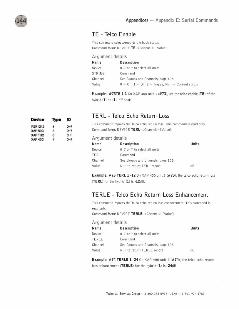
144
Technical Services Group ~ 1-800-283-5936 (USA) ~ 1-801-974-3760
Appendices ~ Appendix E: Serial Commands
TE - Telco EnableThis command selects/reports the hook status.Command form: DEVICE TE <Channel> [Value]
Argument detailsName DescriptionDevice 0—7 or * to select all unitsSTRING Command Channel See Groups and Channels, page 105Value 0 = Off, 1 = On, 2 = Toggle, Null = Current status
Example: #73TE 1 1 On XAP 400 unit 3 (#73), set the telco enable (TE) of the
hybrid (1) on (1), off hook.
TERL - Telco Echo Return LossThis command reports the Telco echo return loss. This command is read only. Command form: DEVICE TERL <Channel> [Value]
Argument detailsName Description UnitsDevice 0—7 or * to select all unitsTERL Command Channel See Groups and Channels, page 105Value Null to return TERL report dB
Example: #73 TERL 1 -12 On XAP 400 unit 3 (#73), the telco echo return loss
(TERL) for the hybrid (1) is -12dB.
TERLE - Telco Echo Return Loss EnhancementThis command reports the Telco echo return loss enhancement. This command is read only.Command form: DEVICE TERLE <Channel> [Value]
Argument detailsName Description UnitsDevice 0—7 or * to select all unitsTERLE Command Channel See Groups and Channels, page 105Value Null to return TERLE report dB
Example: #74 TERLE 1 -24 On XAP 400 unit 4 (#74), the telco echo return
loss enhancement (TERLE) for the hybrid (1) is -24dB.
145
Technical Services Group ~ 1-800-283-5936 (USA) ~ 1-801-974-3760
Appendices ~ Appendix E: Serial Commands
TOUT - Time Out Select
This command selects/reports the inactivity time out before returning to the unit title
screen.
Command form: DEVICE TOUT [Value]
Argument detailsName DescriptionDevice 0—7 or * to select all unitsTOUT Command Value 0 = Off, 1—15 (select time out in minutes)
Null = Current mode
Example: #72 TOUT 5 On XAP 400 unit 2 (#72), the front panel of the unit will
time out (TOUT) after 5 minutes.
UID - Unit IDThis command reports the unit ID. This command is read only.Command form: DEVICE UID [Value]
Argument detailsName Description UnitsDevice 0—7 or * to select all unitsUID Command Value Null to return value Hexadecimal
Example: #73 UID B465F991 The unit ID number (UID) received from XAP 400
unit 3 (#73), is B456F991.
VER - VersionThis command reports the firmware version of the unit. This command is read only.Command form: DEVICE VER [Value]
Argument detailsName DescriptionDevice 0—7 or * to select all unitsVER Command Value Null to return value
Example: #74 VER 1.0.0 The version of the firmware (VER) programmed into
XAP 400 unit 4 (#74), is 1.0.0.
146
Technical Services Group ~ 1-800-283-5936 (USA) ~ 1-801-974-3760
Appendices ~ Appendix F: Warranty
ClearOne Communications, Inc. (Manufacturer) warrants that this product is free of
defects in both materials and workmanship. Should any part of this product be
defective, the Manufacturer agrees, at its option, to:
A. Repair or replace any defective part free of charge (except transportation
charges) for a period of one year from the date the end user is invoiced for
the product, provided the end user returns the product to ClearOne
Communications or an authorized ClearOne dealer according to the Product
Return and Repair Policy set forth below;
B. Furnish replacement for any defective parts in the product for a period of
one year from the date the end user is invoiced for the product, provided the
end user provides proof of purchase that demonstrates that the product is
still within the warranty period. Replacement parts shall be furnished
without charge, except labor and transportation.
This warranty excludes assembled products not manufactured by the Manufacturer
whether or not they are incorporated in a Manufacturer product or sold under a
Manufacturer part or model number.
Product Return and Repair Policy
1. Return to Seller if Purchased Through an Authorized Dealer
a. Proof of purchase date from reseller within warranty period must be
provided by the end user.
b. Seller may, at its discretion, provide an immediate exchange or repair
or may return the unit to the Manufacturer for repair.
2. Return to Manufacturer
a. An RMA (return merchandise authorization) number must be issued to
the end user from ClearOne technical support.
b. The end user must return the product to ClearOne with proof of
purchase (showing purchase date) for a warranty claim, and display the
RMA number on the outside of the shipping package.
THIS WARRANTY IS VOID IF:
A. The product has been damaged by negligence, accident, act of God, or
mishandling, or has not been operated in accordance with the procedures
described in the operating and technical instructions; or,
Appendix F: Warranty
147
Technical Services Group ~ 1-800-283-5936 (USA) ~ 1-801-974-3760
Appendices ~ Appendix F: Warranty
B. The product has been altered or repaired by other than the Manufacturer or
an authorized service representative of the Manufacturer; or,
C. Adaptations or accessories other than those manufactured or provided by the
Manufacturer have been made or attached to the product which, in the
determination of the Manufacturer, shall have affected the performance,
safety or reliability of the product; or,
D. The product’s original serial number has been modified or removed.
NO OTHER WARRANTY, EXPRESS OR IMPLIED, INCLUDING WARRANTIES
OF MERCHANTABILITY OR FITNESS FOR ANY PARTICULAR USE, APPLIES
TO THE PRODUCT. MANUFACTURER’S MAXIMUM LIABILITY HEREUNDER
SHALL BE THE AMOUNT PAID BY THE END USER FOR THE PRODUCT. No
person or entity authorized to assume any obligation or other liability in connection
with the products. No action, regardless of form, arising out of or relating to the
product or this warranty, may be brought by end user more than one (1) year after
the cause of action has accrued.
Manufacturer shall not be liable for punitive, consequential, or incidental
damages, expenses, or loss of revenue or property, inconvenience, or interruption
in operation experienced by the end user due to a malfunction in the purchased
product. No warranty service performed on any product shall extend the
applicable warranty period.
In case of unsatisfactory operation, the end user shall promptly notify the
Manufacturer at the address set forth below in writing, giving full particulars as to
the defects or unsatisfactory operation. Upon receipt of such notice, the
Manufacturer will give instructions respecting the shipment of the product, or such
other matters as it elects to honor this warranty as above provided. This warranty
does not cover damage to the product during shipping and the Manufacturer
assumes no responsibility for such damage. All shipping costs shall be paid by the
customer.
This warranty extends only to the original end user and is not assignable or
transferable. This warranty is governed by the laws of the State of Utah, without
regard to the conflicts of interests provisions thereof.
ClearOne Communications, Inc.
1825 Research Way
Salt Lake City, Utah 84119
148
Technical Services Group ~ 1-800-283-5936 (USA) ~ 1-801-974-3760
Appendices ~ Appendix G: Compliance
Warning: The country code settings must be set for the desired country of
operation in order to ensure proper operation of the XAP 400 and to ensure that
the XAP 400 complies with the countries Telco requirements. Changing these
settings to a country other than the intended country of operation may cause the
XAP 400 to be non-compliant.
FCC Part 15 Compliance
This equipment has been tested and found to comply with the limits for a Class A
digital device, pursuant to Part 15 of the FCC rules. These limits are designed to
provide reasonable protection against harmful interference when the equipment is
operated in a commercial environment. This equipment generates, uses, and can
radiate radio frequency energy and, if not installed and used in accordance with the
instruction manual, may cause harmful interference to radio communications.
Operation of this equipment in a residential area is likely to cause harmful
interference, in which case the user will be required to correct the interference at
his/her own expense.
Changes or modifications not expressly approved by ClearOne
Communications could void the user’s authority to operate the equipment.
FCC Part 68 Compliance
FCC Registration Number: US:FBIBROOBXAP400 Ringer Equivalence Number
(REN): 0.0B(ac)
A label containing, among other information, the FCC registration number and
Ringer Equivalence Number (REN) for this equipment is prominently posted on the
top plate, near the rear of the equipment. If requested, this information must be
provided to your telephone company. USOC Jacks: This device uses RJ-11C and
RJ21X terminal jacks.
The REN is used to determine the quantity of devices, which may be
connected to the telephone line. Excessive RENs on the telephone line may result
in the devices not ringing in response to an incoming call. In most, but not all
areas, the sum of the RENs should not exceed five (5). To be certain of the number
of devices that may be connected to the line, as determined by the total RENs,
contact the telephone company to obtain the maximum RENs for the calling area.
Appendix G: Compliance
149
Technical Services Group ~ 1-800-283-5936 (USA) ~ 1-801-974-3760
Appendices ~ Appendix G: Compliance
If this equipment causes harm to the telephone network, the telephone
company will notify you in advance that temporary discontinuance of service may
be required. If advance notice is not practical, the telephone company will notify
the customer as soon as possible. Also, you will be advised of your right to file a
complaint with the FCC if you believe it is necessary.
The telephone company may make changes in its facilities, equipment,
operations, or procedures that could affect the operation of the equipment. If this
happens, the telephone company will provide advance notice for you to make the
necessary modifications in order to maintain uninterrupted service.
If you experience problems with this equipment, contact ClearOne
Communications, 1825 Research Way, Salt Lake City, Utah 84119, or by phone
at (801) 975-7200 for repair and warranty information. If the trouble is causing
harm to the telephone network, the telephone company may request you remove
the equipment from the network until the problem is resolved.
No user serviceable parts are contained in this product. If damage or
malfunction occurs, contact ClearOne Communications for instructions on its
repair or return.
This equipment cannot be used on telephone company provided coin service.
Connection to Party Line Service is subject to state tariffs.
IC Compliance
IC Certification Number: 1970A 12023
Ringer Equivalence Number (REN): 0.0B(ac)
NOTICE: The Industry of Canada label identifies certified equipment. This
certification means that the equipment meets certain telecommunications network
protective operational and safety requirements. The Department does not guarantee
the equipment will operate to the user's satisfaction.
Before installing this equipment, users should ensure that it is permissible to
be connected to the facilities of the local telecommunications company. The
equipment must also be installed using an acceptable method of connection. In
some cases, the company's inside wiring associated with a single line individual
service may be extended by means of a certified connector assembly (telephone
extension cord). The customer should be aware that compliance with the above
conditions may not prevent degradation of service in some situations.
Repairs to certified equipment should be made by an authorized Canadian
maintenance facility designated by ClearOne Communications. Any repairs or
150
Technical Services Group ~ 1-800-283-5936 (USA) ~ 1-801-974-3760
Appendices ~ Appendix G: Compliance
alterations made by the user to this equipment, or equipment malfunctions, may
give the telecommunications company cause to request the user to disconnect the
equipment.
Users should ensure for their own protection that the electrical ground
connections of the power utility, telephone lines and internal metallic water pipe
system, if present, are connected together. This precaution may be particularly
important in rural areas.
Safety Information
CAUTION: Users should not attempt to make electrical ground connections
themselves, but should contact the appropriate electrical inspection authority, or
electrician, as appropriate.
European Compliance
This equipment has been approved in accordance with Council Directive 1999/5/EC
“Radio Equipment and Telecommunications Equipment.”
Conformity of the equipment with the guidelines below is attested by the
CE mark.
EC Declaration of Conformity
Application of Council Directive(s): 1999/5/EC Radio equipment and
Telecommunications Terminal
Equipment (R&TTE) Directive
Manufacturer’s Name: ClearOne Communications
Manufacturer’s Address: 1825 West Research Way
Salt Lake City, Utah 84119 U.S.A.
Model No.: XAP 400
Standard(s) to which Conformity is declared:
89/336/EEC “Electromagnetic Compatibility (EMC) Directive”:
EN 55022: 1994 (Emissions) Specification for limits and methods
of measurement of radio interference
characteristics of information
technology equipment.
151
Technical Services Group ~ 1-800-283-5936 (USA) ~ 1-801-974-3760
Appendices ~ Appendix G: Compliance
EN 61000-3-2:1995/A1/A2:1998 Part 3: Limits — Section 2: Limits
for harmonic current emissions.
EN 61000-3-3:1995 Section 3: Limitation of voltage
fluctuations and flicker in low
voltage supply systems for equipment
with rated current up to and
including 16 A.
EN 55024: 1998 (Immunity) Information technology equipment —
Immunity characteristics — Limits
and methods of measurement.
EN 61000-4-2: 1995/A1:1998 Electrostatic Discharge
EN 61000-4-3: 1996/A1:1998 Radiated RF Immunity
EN 61000-4-4: 1995 Electrical Fast Transients
EN 61000-4-5: 1995 Lightning Surge
EN 61000-4-6: 1996 Conducted RF Immunity
EN 61000-4-8: 1993 Radiated Magnetic Field Immunity
EN 61000-4-11: 1994 Voltage Dips and Voltage
Interruptions
73/23/EEC “Low Voltage Directive (LVD)”:
EN 60950: 1992 Safety of Information Technology
Equipment, Including A1, A2, A3,
A4 and A11 Electrical Business
Equipment.
Telecommunications Terminal Equipment:
CTR21 Attachment requirements for pan-European approval for connection to the
Public Switched Telephone Network.
152
Technical Services Group ~ 1-800-283-5936 (USA) ~ 1-801-974-3760
Glossary
Acoustic Echo Cancellation (AEC) A process in which acoustical echo is
removed from a signal. AEC can be used to remove unwanted signals from mic audio
if the unwanted acoustic signal is available separately as an electronic signal.
Adaptive Ambient This portion of the mixer monitors the varying ambient noise
level in the room and changes the threshold level at which a microphone gates on.
Ambient Level The manually-set background noise level upon which the XAP 400
bases gating protocols. Used only if the Adaptive Ambient feature isn’t used.
Ambient Noise The existing room-level noise, such as that caused by ventilation
systems, paper shuffling, and background chatter.
Amplitude Plot A plot of amplitude (-18 to 18dB) vs. frequency (20Hz to 20kHz)
on a logarithmic scale.
Attack Time This signal parameter determines how quickly compression is enabled.
It is calibrated in milliseconds.
Attenuation A reduction of signal amplitude.
Audible Hook Indication The unit signals when it goes on or off hook with a
series of beeps. This indication can be turned on or off in the Telco Configuration
window and the level can be adjusted.
Audible Ringer Indication When a call comes in, you can hear it ring if Audible
Ringer Indication is turned on in the Telco Configuration window. The ringer level
can also be adjusted.
Audio Processor A device that modifies an audio signal in response to certain
requirements.
Audio routing The process of routing input signals (Mics 1—4, Inputs 5—8, From
Telco, From E-bus, From Processing) to output destinations (Output 1—9, To Telco, To
E-bus, To Processing) in the Matrix screen.
Automatic Gain Control (AGC) Automatically increases or decreases audio gain
to maintain a consistent audio level.
Automatic Gating Automatically gates microphones on or off based on input levels
and other parameters programmed into the XAP 400.
Automatic Level Control (ALC) ALC can be selected for the telco input and is
designed to keep soft and loud telephone participants at a consistent level. ALC can
be turned on (default) or off.
Glossary
153
Technical Services Group ~ 1-800-283-5936 (USA) ~ 1-801-974-3760
Glossary
Auxiliary audio Audio that comes from line level audio sources such as video
codecs, TH2s, and CD players.
Bandwidth The difference between the lower and upper 3dB end points of an audio
band. Also, the range or differences between the limiting frequencies of a continuous
frequency band.
Baud Rate The number of signal transitions per second, or the clock rate of the
serial bit stream in hertz. Given 7 or 8 bits for data plus start and stop, the
approximate ASCII character transmission rate is one-tenth the baud rate.
Chairman Override Provides gating priority for chairman override enabled
microphones within the same gating group. When a mic with chairman override
gates on, all mics that don’t have chairman override enabled and are in the same
gating group will gate off.
Clipping A condition in which a signal level exceeds the maximum level a circuit
can handle. This is usually caused by improper gating parameters and gain settings.
It causes distortion and typically leads to listener fatigue and accelerated failure of
loudspeaker drivers.
Compression An induced reduction in the dynamic range of part or all of an audio
signal. Compression is usually used to protect individual loudspeaker components
from the damaging effects of transients.
Compressor The compressor is part of the processing settings and allows you to
change the gain transfer characteristics of the signal path and to control the
dynamics of the signal.
Configuration mode Configuration mode is the default mode in G-Ware and is
used for system setup. It provides access to the Matrix and Flow Screens. See also
Preset mode and Macro mode.
Control bus Part of the expansion bus, the control bus passes control information
to the units. Control is not affected by master/slave settings and will continue to
function even if the units are not using the audio channels.
Constant Directivity Horn Equalizer (CD Horn EQ) Horn drivers commonly
used in arrays in arenas and auditoriums have an inherent 6dB/octave high frequency
rolloff. The XAP 400’s CD Horn EQ compensates for this characteristic.
Crossover A device that passes designated frequency segments of an audio signal to
various loudspeaker elements in a sound system.
• Bessel A crossover using a low-pass filter design characterized by a linear
phase response. This results in a constant time delay throughout the passband.
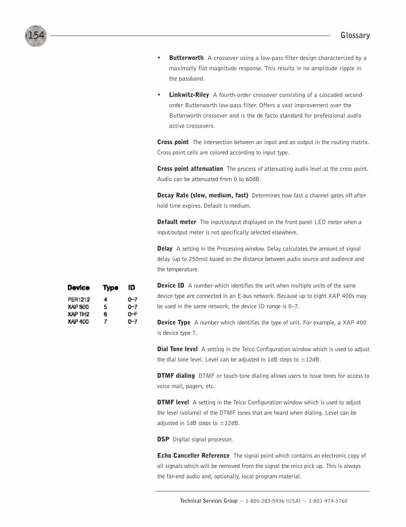
154
Technical Services Group ~ 1-800-283-5936 (USA) ~ 1-801-974-3760
Glossary
• Butterworth A crossover using a low-pass filter design characterized by a
maximally flat magnitude response. This results in no amplitude ripple in
the passband.
• Linkwitz-Riley A fourth-order crossover consisting of a cascaded second-
order Butterworth low-pass filter. Offers a vast improvement over the
Butterworth crossover and is the de facto standard for professional audio
active crossovers.
Cross point The intersection between an input and an output in the routing matrix.
Cross point cells are colored according to input type.
Cross point attenuation The process of attenuating audio level at the cross point.
Audio can be attenuated from 0 to 60dB.
Decay Rate (slow, medium, fast) Determines how fast a channel gates off after
hold time expires. Default is medium.
Default meter The input/output displayed on the front panel LED meter when a
input/output meter is not specifically selected elsewhere.
Delay A setting in the Processing window. Delay calculates the amount of signal
delay (up to 250ms) based on the distance between audio source and audience and
the temperature.
Device ID A number which identifies the unit when multiple units of the same
device type are connected in an E-bus network. Because up to eight XAP 400s may
be used in the same network, the device ID range is 0—7.
Device Type A number which identifies the type of unit. For example, a XAP 400
is device type 7.
Dial Tone level A setting in the Telco Configuration window which is used to adjust
the dial tone level. Level can be adjusted in 1dB steps to ±12dB.
DTMF dialing DTMF or touch-tone dialing allows users to issue tones for access to
voice mail, pagers, etc.
DTMF level A setting in the Telco Configuration window which is used to adjust
the level (volume) of the DTMF tones that are heard when dialing. Level can be
adjusted in 1dB steps to ±12dB.
DSP Digital signal processor.
Echo Canceller Reference The signal point which contains an electronic copy of
all signals which will be removed from the signal the mics pick up. This is always
the far-end audio and, optionally, local program material.
155
Technical Services Group ~ 1-800-283-5936 (USA) ~ 1-801-974-3760
Glossary
EC Reference summing The ability to include multiple signals in a single
reference. See also Virtual Reference.
ERL Found in the Acoustic Echo Canceller window, the echo return loss (ERL)
meter shows the coupling between the reference signal and the input to the echo
canceller–the ratio of the two levels.
ERLE Found in the Acoustic Echo Canceller window, the echo return loss
enhancement (ERLE) meter shows the loss through the echo cancellation and non-
linear processing chain–the ratio of the two levels.
Expansion Bus Consists of two RJ-45 connectors on the rear panel of the XAP
400. An Expansion Bus allows multiple XAP 400s to be networked together using
category five twisted-pair (10BaseT) cable.
Expansion Bus reference One of the echo cancellation/PA adapt reference
options. The Expansion Bus reference allows you to reference an output on a
networked unit.
Filter A device that passes and blocks audio signals based on user-definable
requirements of the system.
• All Pass A filter that provides only phase shift or phase delay without
appreciably changing the magnitude characteristic. The filter produces a flat
amplitude response. It is useful for matching the delay of two processing
channels with different delays.
• High Pass A filter that passes high signal frequencies while attenuating low
frequencies. The gain or loss
• High Shelving Provides boosting or attenuation of frequencies above a
designated frequency. The transition between the spectrum above and below
the designated frequency occurs at a fixed 6dB/octave rate. The gain or loss
above the corner frequency is adjustable to +/- 15dB.
• Low Pass A filter that passes low frequencies while attenuating high
frequencies.
• Low Shelving Provides boosting or attenuation of frequencies below a
designated frequency. The transition between the spectrum above and below
the designated frequency occurs at a fixed 6dB/octave rate. The gain or loss
below the corner frequency is adjustable to +/- 15dB.
Filter Display A group of nodes plotted on a logarithmic scale. The
XAP 400’s filter display can be accessed through the Inputs 1-8, From Processing,
or To Processing windows.
156
Technical Services Group ~ 1-800-283-5936 (USA) ~ 1-801-974-3760
Glossary
First Mic Priority Increases the audio level required to gate on additional
microphones after the first mic is on. This helps ensure that only one mic gates on
when a person speaks.
Flow control The regulation of the transmission and reception of data.
Flow Screen The Flow Screen is the main access window for G-Ware features and
unit configuration. It also shows a detailed block diagram of the audio signal–
presenting a graphical explanation of each stage in the signal path.
Gain The amount a signal is increased over a given reference, typically 0. Normally
specified in dB (decibels). On the XAP 400, gain is adjustable from -65 to 20dB
(85dB range) in .5dB increments.
Gain Structure The configuration of parameters which define gain adjustment of a
signal. The optimal input gain setting is one which provides both an adequate signal-
to-noise ratio and reasonable headroom.
Gate The activation and deactivation of microphones.
• Auto The microphone will gate on according to the input level, assigned
gating parmeters, and gating group.
• Manual On The microphone will gate on unless it exceeds the NOM
requirements of the gating group.
• Manual Off The microphone is deactivated.
Gate Ratio Specifies how much louder the microphone audio level must be above
the ambient sound level before a microphone gates on.
Gating controls The gating parameters that are assigned to a gating group:
Maximum Number of Mics, First Mic Priority, and Last Mic Mode.
Gating groups A set of gating parameters which can be applied to local
microphones (Internal 1—4) or to microphones connected to other units on the
network (Global A—D). Gating groups provide greater flexibility and control of mics.
Gentner Distributed Echo Cancellation ClearOne’s proprietary system for
applying echo cancellation individually to each mic input.
Global gating bus Part of the expansion bus, these four mix-minus buses pass mic
status and gate parameter information such as First Mic Priority and Max NOM.
GPIO (general purpose input/output) The Control/Status A and B ports on the
XAP 400 unit. The GPIO Builder is used to program Control/Status A pins.
G-Ware Software The XAP 400’s setup and configuration software.
157
Technical Services Group ~ 1-800-283-5936 (USA) ~ 1-801-974-3760
Glossary
Hold Time The length of time that a microphone remains on after the voice (input)
level drops below the gate ratio. This can be used to prevent the microphone from
gating off during brief pauses in speech.
Last Mic Mode Sets the last-activated mic to Last On, Mic 1-8, or Off. The Last
On setting leaves the last-activated mic gated on until another mic input gates on.
Macro A series of user-created instructions, stored within the unit, which can be
executed from an RS-232 command or contact closure.
Macro Mode The G-Ware mode that allows you to customize and execute macro
commands for a XAP 400 unit or network.
Manual Gating Provides the ability to gate a microphone on or off manually.
Matrix Mixer A mixer that allows routing of any input or combination of inputs to
an output or any combination of outputs. In the case of the XAP 400, the matrix
mixer permits level control at each cross point in the matrix.
Matrix Screen The Matrix Screen facilitates the routing of any input to any output
or combination of outputs.
Maximum Number of Mics Sets the maximum number of mics that can be gated
on simultaneously.
Microphone Activation A condition in which a microphone is gated on.
Microphone Mixing A situation in which audio from mics on different signal lines
are mixed together. All mic signals can be mixed to one signal line, any or all
outputs, or mixed into separate groups. Mic signals can also be processed together
or individually.
Microphone 1 Mode Reverts mic assignment to a designated mic when all mics
gate off.
Min/Max adjust The yellow and blue upper and lower limit arows on gain scales
are used to create minimum and maximum gain level limits. These limits only apply
when using relative gain commnds; absolute gain commands can exceed the min and
max limits. Min and max limits apply to all serially connected control devices and
preven users from adjusting levels beyond the min/max levels provided relative gain
commands are used.
Mixer mode The mixer mode has two settings: master and slave. Mixer mode can
be configured from the front panel or in the Unit Properties window.
Mute A condition in which an audio signal is attenuated below the audible
threshold.
158
Technical Services Group ~ 1-800-283-5936 (USA) ~ 1-801-974-3760
Glossary
Noise Cancellation A process through which ambient noise is removed from a
signal.
Non-linear processing (NLP) NLP increaess the power of echo cancellation for
difficult acoustical environments. NLP has four settings: Soft (6dB), Medium
(12dB), Aggressive (18dB), and Off. NLP settings are found in the Acoustic Echo
Cancellation window.
Number of Open Mics (NOM)/Constant Gain Mode Adjusts the output level
based on the number of mics gated on and routed to an output.
O—R buses These four audio buses communicate NOM count and mic mixing
parameters.
Off Attenuation The amount of level reduction a microphone is given when the
microphone is not gated on.
PA Adaptive Mode The XAP 400 recognizes how much loudspeaker audio is
picked up by the microphones and then uses this level as the new ambient level when
audio is present at the power amplifier. This prevents loudspeaker audio from gating
on a microphone, while still allowing people in the room to gate on microphones as
they speak.
PA Adapt/AEC Reference This G-Ware setting determines which output (typically
for a loudspeaker) is used as a reference for an input.
PA Adapt/AEC Reference bus This bus carries reference information making it
possible for an input to reference an output on another linked unit.
Parametric Equalizer (PEQ) A multi-band variable equalizer with control of
gain, center frequency, and bandwidth. A properly configured PEQ enables the XAP
400 to offset speaker or room acoustic deficiencies.
Passwords The XAP 400 features several passwords to protect system
configuration.
• Front panel The front panel password prevents a user from changing settings
in the front panel LCD menus. The password can be set from the front panel or
through G-Ware.
• Macro The macro password is created in the Unit Properties window and
makes it possible to lock certain macros. A locked macro can be run without
the password. However, a password must be entered to edit the macro.
• Modem The modem password can be created serially using the MPASS
command or through G-Ware in the Unit Properties window. The password is
required to allow remote modem access.
159
Technical Services Group ~ 1-800-283-5936 (USA) ~ 1-801-974-3760
• Preset The preset pasword is created in the Unit Properties window and makes
it possible to lock certain presets. A locked preset can be executed without the
password. However, a password must be entered to edit the preset.
• Site file (File Access) The site file password is set in the Site Properties
window and will lock the site file. Users must enter the password in order to
open the site file.
Phantom Power Power supplied by the XAP 400 to power most condenser
microphones. The XAP 400 provides 24 volts of phantom power. This feature can be
switched off for devices not requiring phantom power.
Phase Plot A plot of phase angle (-180 to 180 degrees) vs. frequency (20Hz to
20kHz) on a logarithmic scale.
Pink Noise An audio test signal containing all the frequencies in a given audio
spectrum, with equal energy in each octave.
Preset One of 32 configurable memories in the XAP 400. A preset can be
programmed with a variety of routing, level, gating, delay, filter, and equalizer
settings to meet specific application requirements.
Preset Mask Defines whether a contact closure activates on a low or high signal on
the rear panel of the unit.
Preset Mode Preset mode is used to create presets and is accessed from the G-
Ware toolbar.
Processing blocks There are four processing blocks or channels (A—D) in the XAP
400 each with 15 filters, delay, and a compressor for pinpoint audio configuration. A
single input or group of inputs can be routed through a processing block and then
routed to an output or multiple outputs.
Q Quality factor. It is the ratio of the center frequency divided by the bandwidth. Q
reflects an inverse relationship to the bandwidth, and adjusts from .02:1 to 40:1 on
the XAP 400.
Ratio The amount of compression applied to the output signal compared with the
input signal as the signal exceeds the threshold level.
Receive audio Audio being received from the telephone line (From Telco).
Release time Release is a parameter which determines how quickly compression is
released after the input signal drops below the threshold.
Reverberation A diffused acoustic energy field fed and maintained by sound
reflections from the room surfaces.
Glossary
160
Technical Services Group ~ 1-800-283-5936 (USA) ~ 1-801-974-3760
Glossary
S—Z buses These eight buses are defaulted as auxiliary mix buses. They are used to
route auxiliary audio to and from other units on the network. These buses are also
used as mic mix buses when NOM count is not required.
Serial Command A bit description designed to execute an instruction or command.
Serial mode The serial mode determines the format in which serial commands
return–text or binary. The mode defaults to Binary when G-Ware is connected
and to Text when disconnected. Contact technical support for instructions on using
Binary mode.
Signal Delay Used for:
• Compensating for physical placement of multiple drivers in a cluster–toalign points of acoustic origin in the same plane.
• Ensure matching arrival times at listeners from multiple loudspeakerdrivers.
• Using the Haas effect to maintain localization of the source, even with adistributed system.
Signal Generator A device for generating a reference tone for sound system
calibration purposes.
Site file A site file is a file created by G-Ware which is saved on your computer.
The site file contains all information about a particular installation including all unit
settings and properties. It also provides G-Ware with the necessary informaiton to
communicate with the site hardware using your PC.
Site properties The Site Properties window opens when you select New Site from
the File menu or click on the New Site button on the toolbar. It allows you to enter
information about the site as well as configure the communication and security
settings.
Speech Leveler Essentially an AGC applied to a speech signal after processing by
a noise cancellation stage. Acts only on voice signals. Does not pull up the noise floor
during periods of no signal.
Table View Displays the numerical values of the filter parameters for all nodes of
the active filter display.
TERL The telco echo return loss (TERL) meter shows the coupling between the
transmit signal and the input to the telephone echo canceller. It is the ratio of the
two levels.
TERLE The telco echo return loss enhancement (TERLE) meter shows the loss
through the telephone echo cancellation process. It is the ratio of the two levels.
161
Technical Services Group ~ 1-800-283-5936 (USA) ~ 1-801-974-3760
Glossary
Threshold The upper or lower level at which a signal processing mechanism begins
or terminates operation.
Transmit audio Audio being sent to the telephone line (To Telco).
Unit properties The Unit Properties window opens when you add a new unit to the
site. It allows you to enter information about the unit as well as configure the
communication and security settings.
Virtual reference Virtual references are echo cancellation reference points.
Multiple signals can be included in each of the four virtual references thus allowing
you to reference multiple signals without sacrificing an analog output. You can open
the Virtual Reference window from the G-Ware toolbar or from the Acoustic Echo
Cancellation window.
White Noise Acoustical noise with equal energy throughout a given frequency
range.
162
Technical Services Group ~ 1-800-283-5936 (USA) ~ 1-801-974-3760
Index
Aacoustic echo cancellation 33—35, 40 158
echo return loss (ERL) 35
echo return loss enhancement (ERLE) 35
non-linear processing (NLP) 35
AEC settings 33—35total echo reduction 35
adaptive ambient 38, 39, 96, 109, 152
add unit 24
AEC see acoustic echo cancellation
AEC reference 7, 33, 38, 40, 138, 158
AGC see automatic gain control
ALC see automatic level control
All Pass 36, 51, 95, 97, 119, 155
ambient level 38—39, 42, 112, 152, 158
ambient noise 35, 38, 58, 152
answer a call 71, 104 see also auto-answer
attack time see Compressor
Audible Hook Indication 56, 152
Audible Ringer Indication 56, 71, 108, 138
audio routing 6, 27, 29, 30, 31, 59, 152
O—Z routing 30
Process A—D routing 30
Auto Sweep 75 see also Signal Generator
auto-adapt 56
auto-answer 16, 56, 72, 90, 107, 109
auto-detect 24
auto-disconnect 56, 107, 110
automatic gain control 32—33, 43—44, 111,
active gain 33
response time 33
target level 33
automatic level control 58, 107, 112, 152
auxiliary audio 7, 30, 33, 44, 153, 160
Bbandwidth 36, 37, 118, 119, 153, 158, 159
baud rate 16, 23, 25, 90, 93, 107, 112, 153
Ccall progression 56
category five twisted-pair cable 11
Chairman Override 38, 94, 107, 113, 153
Clear Matrix 30
clear password 15
clipping 43, 45, 47, 54, 58, 153
codecs see video codecs
COM port 21, 23
command line 64, 67, 69, 104
Command Strings 93
compare site 76
Compressor 49—51, 95, 107, 113, 114, 153
attack time 49, 51, 111, 114, 152
compression meter 51
group 50
input meter 51
post compressor gain 50
ratio 51
release time 49, 51
threshold 50
connect 10, 24
sync to document 24
Sync to Unit(s) 24
constant gain 46, 47, 57, 158
control bus 6, 7, 153
Control Panels 6, 59, 61, 64, 89—92,101—103
connecting 101
Select panel 91
Volume panel 90
Control/Status A 10, 87, 98, 99, 156
Control/Status B 61, 98
copy and paste 28, 31, 77, 78
cross point 29, 30—31, 60, 132, 154, 157
Cross Point Attenuation Dial window 30
crossover 53, 95, 119, 153, 154
DDEC see Gentner Distributed Echo Cancellation
default meter 16, 18, 25, 107, 116, 154
delay 6, 49, 53, 54, 59, 95, 115, 116, 154
device ID 12, 15, 25, 89, 106, 117, 154
device type 68, 87, 89, 106, 154
Dial interface 72, 73mute 72
Index
163
Technical Services Group ~ 1-800-283-5936 (USA) ~ 1-801-974-3760
dial multiple numbers 72
Dial Tone Level 56, 154
Distributed Echo Cancellation see Gentner
Distributed Echo Cancellation
Document Compare Utility 75
DSP 1, 107, 117, 154
DTMF 2, 73, 107, 117, 118, 154
DTMF level 56, 154
EEC Reference 59, 60, 106 see also AEC
reference
ERL 16, 17, 35, 155
ERLE 16, 17, 35, 155
Execute Preset 59, 64
expansion bus 41, 128, 155
connections 9, 11
labels 48
network 6, 11, 73, 128
reference 33, 40, 62, 138
routing to 29, 30
Expansion Bus In/Out 5, 11, 95
FFile Access Password 23
filter 35—37, 51—53, 118, 119, 155
First Mic Priority 42, 95, 107, 121, 156
floppy disk 22
flow control 15, 23, 25, 95, 107, 120, 156
Flow Screen 27, 30
front panel control 4, 64 see also LCD menu
front panel passcode 15
GG-Ware 22
installation 22
Program Folder 22
G-Ware Switcher 81
gain structure 43, 45, 47, 54, 156
Gate 6, 7, 38
activation 38
adaptive ambient 38
ambient level 39
auto-gate 38
chairman override 38
decay rate 39
gate ratio 39
hold time 39
manual off 38
manual on 38
off attenuation 39
PA Adaptive mode 38
Gate View 83
Gating Group 38, 41— 42, 60, 123, 156
First Mic Priority 42
Global A—D 41
Internal 1—4 41
Last Mic Mode 42
Max # of Mics 41
Gentner Distributed Echo Cancellation 1, 32,
49, 154
GFirm Firmware Utility 79
Global Gating Groups A-D buses 7
GPIO 5, 27, 61, 63, 64, 71, 87, 93, 105, 156
HHigh Pass 36, 51, 95, 96, 119, 155
hold time 39, 96, 107, 123, 154, 157
hook flash †73, 107, 125
hook flash duration †56
IInputs 1—4 32
AEC 33
AGC/SL 32
filters 35
gate 38
mute 32
NC 35
PA Adapt and AEC Reference 33
phantom power 33
virtual echo cancellation reference 34
Inputs 5—8 44
AGC 44
meters 45
mute 44
Inputs menu 18
gain 18
mute 18
Index
164
Technical Services Group ~ 1-800-283-5936 (USA) ~ 1-801-974-3760
Index
Llabels 27, 29, 48, 60, 61
Last Mic On 107, 126
latency 6
LCD menu 13, 16, 25
LCD menu tree 13
LCD Programming 13
adjust a parameter 14, 15
line level 32, 42, 44, 45, 46, 96
line level outputs 46
loop drop 56, 110
Low Pass 36, 51, 95, 96, 119, 155
MMacro Editor 26, 27, 65, 67, 68, 69
macro password 26, 158
Macro Recorder 27, 67, 69
macros 64—66, 67—70, 105, 128, 158
editing macros 69
Macro Editor 68
macro password 68
Macro Recorder 67
running macros 70
make and disconnect a call 71, 72
master setting 12, 15, 128
Matrix Screen 27—32, 157
Message Log 28, 82
meter 4
Meter menu 16
Default Meter 18
ERL 17
ERLE 17
Inputs 17
Outputs 17
Processing 17
Telco RX 17
Telco TX 17
TERL 17
TERLE 18
Meter reference 19
Meter View 83
Meters 43
post gain 43
post gating 43
post processing 43
pre pain 43
Min/Max limits 42
mixer mode 9, 12, 14, 15, 157
modem 15, 16, 23, 26, 92, 97, 107, 129,
131, 159
modem access 92
password 92
Mute Receive 72, 73
Mute Transmit 72, 73
NNLP see non-linear processing
noise burst †56, 72
noise cancellation 35, 58, 95, 96, 133, 158
NOM 30, 38, 46, 47, 57, 134, 158
non-gated 5, 29, 30, 44, 132
non-linear processing 35, 108, 134, 158
Notch 36, 51, 95, 96, 119
OOff LED/button 4
On LED/button 4
Outputs 1—9 5, 10, 18, 46, 47, 95
mute 46
NOM 46
Outputs menu 18
gain 18
mute 18
O—R buses 6, 30, 158
PPA Adapt and AEC Reference 6, 7, 33, 38,
40, 108, 155, 158
buses 7
PA Adaptive Mode 38
password 26front panel 26file access 23macro password 68modem 26preset password 60
PEQ (parametric equalizer) 36
phantom power 33
pink noise 74
pinouts 97
165
Technical Services Group ~ 1-800-283-5936 (USA) ~ 1-801-974-3760
Index
Control/Status A 98
Control/Status B 99
Line 100
RS-232 97
RS-485 100
Set 100
preset 5, 14, 26, 27, 59—66, 159
creating presets 59
executing preset 64
front panel control 64
multiple presets 59
Preset Configuration pane 59
preset masking 60
preset password 60
preset state 64
Reference Matrix 62
Remote Assignment 61
room combining 65
routing matrix 60
running multiple presets 64
running presets 64
Preset mode 59
Print 28, 31, 62, 76, 77, 78
matrix 31
preset 62
preview 76
reports 78
process meter 54
processing 16, 17, 25, 27, 29, 30, 49—54,
95, 152, 156
Processing A—D 49
compressor 49
delay 53
filters 51
frequency response 52phase 52mute 49
propagation 6, 54
Rre-null 72, 73
receive ALC 56
receive boost 56
Receive Input 85
Receive Output 85
receive reduction 56
release time 114, 160
Remote Builder 27, 61, 88, 89
Remote Panel 6, 10, 64, 88, 100, 101, 102
response time 33, 111 see also automatic gain
control
RJ-45 jumper 11
room combining 5, 59, 61, 64, 65
routing matrix 29, 30, 34, 40, 62, 63, 154
RS-232 10, 11, 12, 87, 92—93, 112, 140
see also serial comands
RS-232 menu 15
Baud Rate 15, 95
Clear Password 16
Flow Control 16
Modem Mode 16
RS-485 Remote Panel A/B Port 6
SSafety Mute 28, 141
security 26
serial commands 5, 71, 72, 73, 92, 104
command responses 104
command structure 104
device type and ID 104
groups and channels 105
list of 107
meter type 106
signal flow 27, 43
site file 23, 24, 61, 76, 159, 160
Site Properties 16, 23, 25, 92, 159
Communication 23
Security 23
Use Modem 23
slave setting 12, 15, 25, 128
specifications 95
Speech Leveler 32, 33
speed dial 56, 73
status bar 28
status lights 28
storage capacity 63, 67
Sync 24, 25, 28
System menu 14
166
Technical Services Group ~ 1-800-283-5936 (USA) ~ 1-801-974-3760
Index
Device ID 15
Firmware Version 15
Lock Panel 14
Run Macro 14
Select Preset 14
Set Passcode 15
Unit ID 15
system requirements 21
S—Z 6, 7, 30, 160
Ttarget level 33
telco adaptation †56
telco configuration 55
telco meters 85
Telco Receive 58
ALC 58
Gain 58
Mute 58
NC 58
TERL 16, 17, 85, 86, 108, 144, 161
TERLE 16, 18, 85, 108, 144, 161
threshold 33, 38—39, 49—51, 96, 111, 114
Tone 74
touch-tone 73
Transmit Input 85
Transmit Output 85
UUnit Properties 25—26, 60, 68, 92
communication 25
country code 25
default meter 25
device ID 25
meter refresh rate 25
preset/macro password 26
security 26
serial echo 25
serial mode 25
unit name 25
unit type 25
use modem 26
Use in preset 87
Vvideo codecs 30, 44, 46, 153
video conferencing 9
Virtual Reference 34, 40, 62, 161
Wwhite noise 74
XXAP IR Remote 88, 89

167
Technical Services Group ~ 1-800-283-5936 (USA) ~ 1-801-974-3760