Embed Size (px)
Citation preview

XAECK100 Automotive Evaluation Kit
XAECK100
Features• Quick and easy evaluation of Cypress’s automotive
imaging technology• Up to 120 dB dynamic range• Autobrite® intelligently adapts to lighting conditions
perfect for extreme mixed lighting situations• High sensitivity and near-infrared response• Parallel and IEEE 1394 connections for high quality
digital image capture• Analog NTSC video• Control settings through IEEE 1394 or I2C • 8-and 12-bit image capture modes• Multiple data formats• Single frame, consecutive frame and AVI capture
modes• User-friendly Windows® software• API for camera control and image capture through
customer-built software• Small and convenient form factor• Monochrome, color, and stereo options available
Functional DescriptionThe XAECK100 is available in monochrome, color, and stereoversions
Monochrome XAECK10001Figure 1 illustrates the contents of a monochromeXAECK10001 evaluation kit.
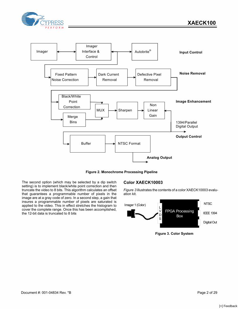
Monochrome Processing Block DiagramFigure 2 illustrates the video processing and controlalgorithms implemented in the control box of theXAECK10001, monochrome camera kit. The pipeline is broken up into three basic categories each ofwhich is described in one of the following sections.
Input ControlThe input control section of the pipeline controls how theimager captures the raw image. This includes control ofparameters such as the frame rate, the integration period andthe dynamic range of the camera. Autobrite® applies primarilyto this section of the pipeline.
Noise Removal The noise removal section of the pipeline corrects fornon-ideal characteristics of the imager. This includes compen-sation for column fixed pattern noise, dark current subtraction,and a non-linear filter that eliminates stuck on or stuck offpixels.
Image EnhancementThe image enhancement section of the pipeline optimizes thevideo for display or 8-bit processing applications. In theseapplications, it is necessary to reduce the bit width of the videofrom 12 bits to 8 bits. The camera supports two options foraccomplishing this. The first option is called merge bins. Merge bins develops anon-linear, but monotonic mapping from the input video to the8-bit output video. The degree to which merge bins affects thevideo can be controlled by specifying a threshold value. Higherthreshold numbers will result in a larger affect. Setting thethreshold to 0 will cause the algorithm to have no affect, andsetting the threshold to values greater than 1000 will cause thealgorithm to approximate histogram equalization. The threshold may be fixed, or expressed as a function of thegray shade. Specifying the threshold as a function of grayshade allows the algorithm to affect bright, moderate, and darkportions of the image differently and is especially suitable fornight applications.
Figure 1. Monochrome System
FPGA ProcessingBox
LVDS
NTSC
IEEE 1394
Digital Out
Imager 1 (Mono)
Monochrome Processing Box SpecificationsProcessing Box
HousingProcessing Base 2 Million Gate Xilinx FPGA
Input Transport Medium LVDS Serial I/FOutput Transport Medium NTSC, IEEE 1394, Parallel
Digital (Single Ended)Serial Control IEEE 1394, Digital Serial
(I2C)Power Supply 6V (external source)
Cypress Semiconductor Corporation • 198 Champion Court • San Jose, CA 95134-1709 • 408-943-2600Document #: 001-04834 Rev. *B Revised May 8, 2006
[+] Feedback
XAECK100
The second option (which may be selected by a dip switchsetting) is to implement black/white point correction and thentruncate the video to 8 bits. This algorithm calculates an offsetthat guarantees a programmable number of pixels in theimage are at a gray code of zero. In a second step, a gain thatinsures a programmable number of pixels are saturated isapplied to the video. This in effect stretches the histogram tocover the complete range. Once this has been accomplished,the 12-bit data is truncated to 8 bits
Color XAECK10003 Figure 3 illustrates the contents of a color XAECK10003 evalu-ation kit.
Figure 2. Monochrome Processing Pipeline
Fixed Pattern Noise Correction
Dark Current Removal
Defective Pixel Removal
Buffer NTSC Format
Input Control
Noise Removal
Image Enhancement
Output Control
Imager Interface &
Control Autobrite® Imager
Sharpen Non
Linear GainMerge
Bins
Black/White Point
Correction MUX
1394/Parallel Digital Output
Analog Output
Figure 3. Color System
FPGA ProcessingBox
LVDS
NTSC
IEEE 1394
Digital Out
Imager 1 (Color)
Document #: 001-04834 Rev. *B Page 2 of 29
[+] Feedback
XAECK100
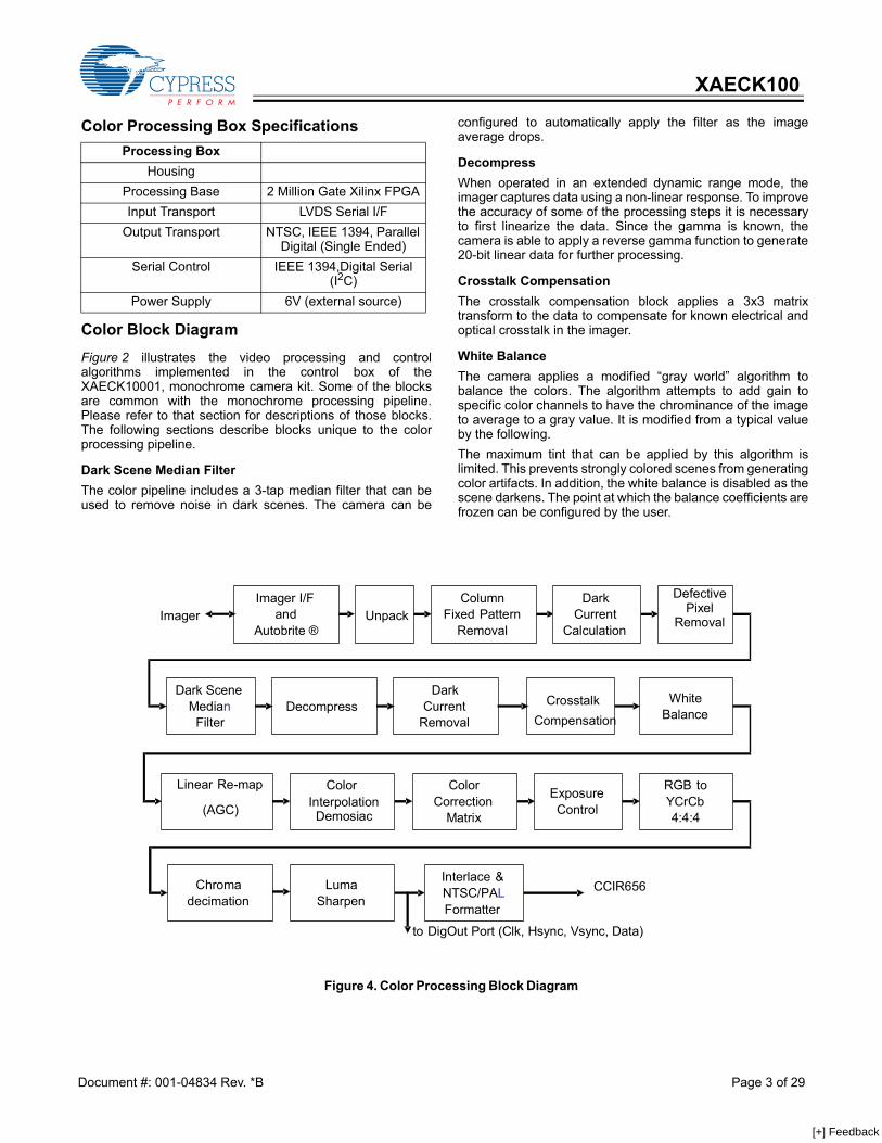
Color Block Diagram Figure 2 illustrates the video processing and controlalgorithms implemented in the control box of theXAECK10001, monochrome camera kit. Some of the blocksare common with the monochrome processing pipeline.Please refer to that section for descriptions of those blocks.The following sections describe blocks unique to the colorprocessing pipeline.
Dark Scene Median Filter The color pipeline includes a 3-tap median filter that can beused to remove noise in dark scenes. The camera can be
configured to automatically apply the filter as the imageaverage drops.
Decompress When operated in an extended dynamic range mode, theimager captures data using a non-linear response. To improvethe accuracy of some of the processing steps it is necessaryto first linearize the data. Since the gamma is known, thecamera is able to apply a reverse gamma function to generate20-bit linear data for further processing.
Crosstalk Compensation The crosstalk compensation block applies a 3x3 matrixtransform to the data to compensate for known electrical andoptical crosstalk in the imager.
White Balance The camera applies a modified “gray world” algorithm tobalance the colors. The algorithm attempts to add gain tospecific color channels to have the chrominance of the imageto average to a gray value. It is modified from a typical valueby the following. The maximum tint that can be applied by this algorithm islimited. This prevents strongly colored scenes from generatingcolor artifacts. In addition, the white balance is disabled as thescene darkens. The point at which the balance coefficients arefrozen can be configured by the user.
Color Processing Box SpecificationsProcessing Box
HousingProcessing Base 2 Million Gate Xilinx FPGAInput Transport LVDS Serial I/F
Output Transport NTSC, IEEE 1394, Parallel Digital (Single Ended)
Serial Control IEEE 1394,Digital Serial (I2C)
Power Supply 6V (external source)
Figure 4. Color Processing Block Diagram
Unpack
DecompressDark Scene
Median Filter
ColumnFixed Pattern
Removal
White Balance
Linear Re-map (AGC)
Color Interpolation Demosiac
ExposureControl
RGB to YCrCb 4:4:4
Interlace &NTSC/PALFormatter
Chroma decimation
CCIR656 LumaSharpen
Dark Current
Removal
CrosstalkCompensation
Color Correction
Matrix
Dark Current
Calculation
to DigOut Port (Clk, Hsync, Vsync, Data)
Imager I/F and
Autobrite ® Imager
Defective Pixel
Removal
Document #: 001-04834 Rev. *B Page 3 of 29
[+] Feedback
XAECK100
Linear Re-mapThe linear remap block attempts to ensure the imagehistogram fills all values in the 8-bit space. It calculates anoffset that ensures a programmable number of pixels areblack—this is also referred to as black point correction. It alsoincludes a gain stage that ensures a programmable number ofpixels are at the saturated value—this is also referred to aswhite point correction
Color InterpolationThe color interpolation block applies a filter to the data togenerate red, green, and blue values for all pixels.
Color Correction MatrixThe color correction matrix applies a color correction functionto compensate for the known transmission of the color filtersand IR blocking filter.
Exposure ControlThe exposure control block applies a non-linear transferfunction to the data to optimize it for display on 8-bit displays.
Luma Sharpen The luma sharpen block in the color system functions similarlyto the same block on the monochrome system with someexceptions. The strength of the luminance sharpening filter has fineradjustments than in the monochrome system. In addition, thestrength of the filter can be automatically scaled with the imageaverage. This prevents the sharpening filter from adding noise
to dark scenes. The behavior of this filter may be modifiedthrough either the IEEE 1394 or I2C Interface.
Stereo XAECK10005 Figure 5 illustrates the contents of a stereo XAECK10005evaluation kit.
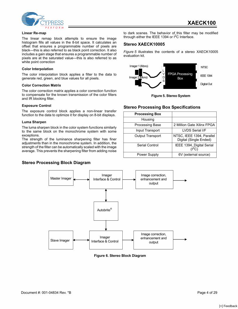
Stereo Processing Block Diagram
Stereo Processing Box SpecificationsProcessing Box
HousingProcessing Base 2 Million Gate Xilinx FPGAInput Transport LVDS Serial I/F
Output Transport NTSC, IEEE 1394, Parallel Digital (Single Ended)
Serial Control IEEE 1394, Digital Serial (I2C)
Power Supply 6V (external source)
Figure 5. Stereo System
FPGA ProcessingBox
LVDS
NTSC
IEEE 1394
Digital Out
Imager 1 (Mono)
Imager 2 (Mono)
Figure 6. Stereo Block Diagram
Image correction,enhancement and
output
Imager Interface & Control
Autobrite®
Master Imager
Slave Imager Imager
Interface & Control
Image correction,enhancement and
output
Document #: 001-04834 Rev. *B Page 4 of 29
[+] Feedback
XAECK100
Additional Stereo Features The image correction, enhancement, and output portions ofthe pipeline are identical to the monochrome system. Pleaserefer to the monochrome section for descriptions of theseprocessing steps.The stereo system differs in the calculation of Autobrite param-eters. In the stereo system, the Autobrite parameters calcu-lated for the master camera are fed to the slave camera toensure the two imagers respond similarly to identical objectsin the scene. In addition to ensuring the settings match, the hardwareensures that the capture timing also matches. The exposureand read out time of the slave camera is locked to the mastercamera to ensure that images are taken at the same time.There is a register bit that indicates when the cameras havesuccessfully synchronized. Note that the performance of thecamera is not guaranteed should the imagers fail tosynchronize for any reason.
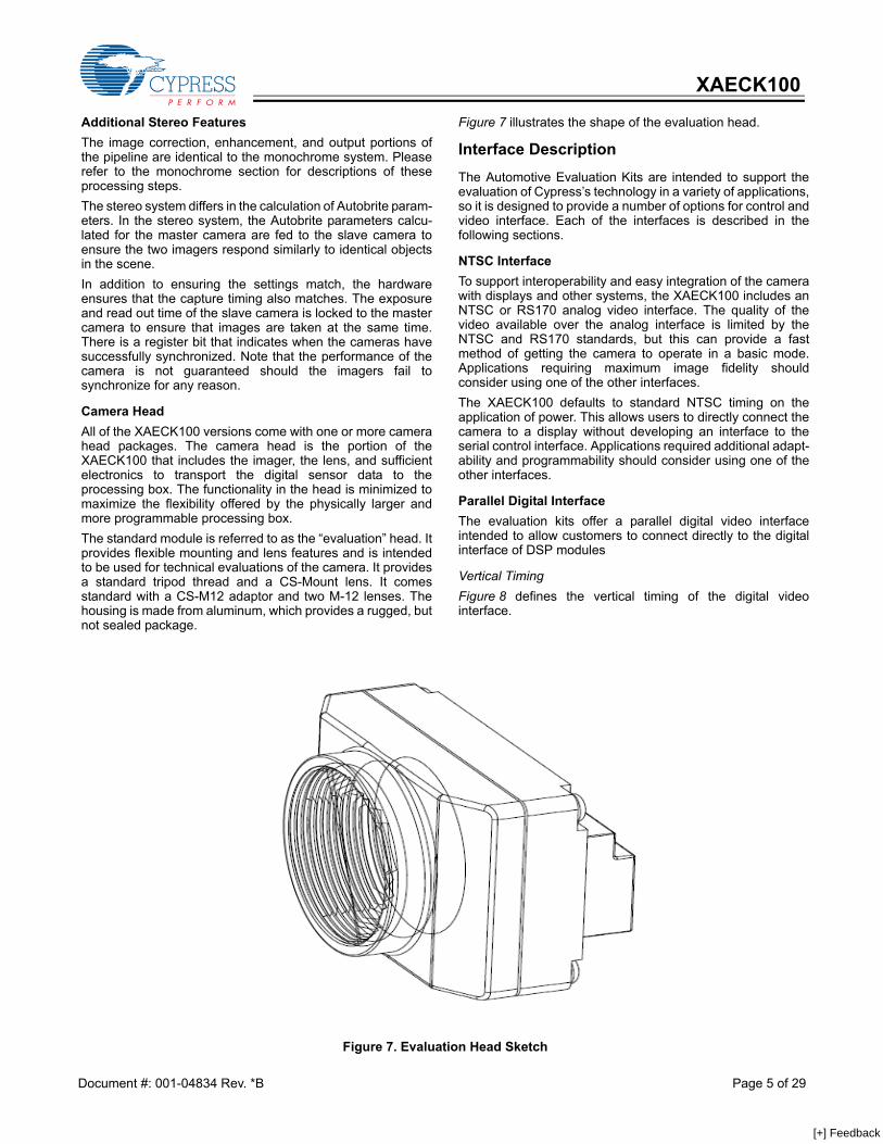
Camera HeadAll of the XAECK100 versions come with one or more camerahead packages. The camera head is the portion of theXAECK100 that includes the imager, the lens, and sufficientelectronics to transport the digital sensor data to theprocessing box. The functionality in the head is minimized tomaximize the flexibility offered by the physically larger andmore programmable processing box. The standard module is referred to as the “evaluation” head. Itprovides flexible mounting and lens features and is intendedto be used for technical evaluations of the camera. It providesa standard tripod thread and a CS-Mount lens. It comesstandard with a CS-M12 adaptor and two M-12 lenses. Thehousing is made from aluminum, which provides a rugged, butnot sealed package.
Figure 7 illustrates the shape of the evaluation head.
Interface Description The Automotive Evaluation Kits are intended to support theevaluation of Cypress’s technology in a variety of applications,so it is designed to provide a number of options for control andvideo interface. Each of the interfaces is described in thefollowing sections.
NTSC Interface To support interoperability and easy integration of the camerawith displays and other systems, the XAECK100 includes anNTSC or RS170 analog video interface. The quality of thevideo available over the analog interface is limited by theNTSC and RS170 standards, but this can provide a fastmethod of getting the camera to operate in a basic mode.Applications requiring maximum image fidelity shouldconsider using one of the other interfaces. The XAECK100 defaults to standard NTSC timing on theapplication of power. This allows users to directly connect thecamera to a display without developing an interface to theserial control interface. Applications required additional adapt-ability and programmability should consider using one of theother interfaces.
Parallel Digital Interface The evaluation kits offer a parallel digital video interfaceintended to allow customers to connect directly to the digitalinterface of DSP modules
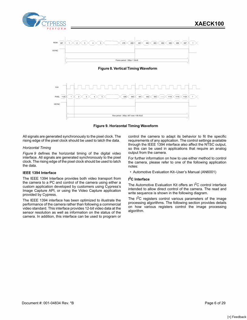
Vertical Timing Figure 8 defines the vertical timing of the digital videointerface.
Figure 7. Evaluation Head Sketch
Document #: 001-04834 Rev. *B Page 5 of 29
[+] Feedback
XAECK100
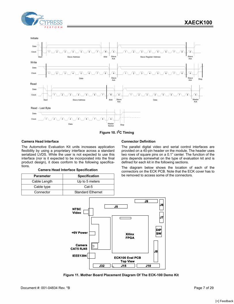
All signals are generated synchronously to the pixel clock. Therising edge of the pixel clock should be used to latch the data.
Horizontal Timing Figure 9 defines the horizontal timing of the digital videointerface. All signals are generated synchronously to the pixelclock. The rising edge of the pixel clock should be used to latchthe data.
IEEE 1394 Interface The IEEE 1394 Interface provides both video transport fromthe camera to a PC and control of the camera using either acustom application developed by customers using Cypress’sImage Capture API, or using the Video Capture applicationprovided by Cypress. The IEEE 1394 interface has been optimized to illustrate theperformance of the camera rather than following a commercialvideo standard. This interface provides 12-bit video data at thesensor resolution as well as information on the status of thecamera. In addition, this interface can be used to program or
control the camera to adapt its behavior to fit the specificrequirements of any application. The control settings availablethrough the IEEE 1394 interface also affect the NTSC output,so this can be used in applications that require an analogoutput from the camera. For further information on how to use either method to controlthe camera, please refer to one of the following applicationnotes: • Automotive Evaluation Kit–User’s Manual (AN6001)
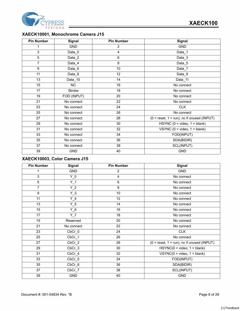
I2C Interface The Automotive Evaluation Kit offers an l2C control interfaceintended to allow direct control of the camera. The read andwrite sequence is shown in the following diagram. The I2C registers control various parameters of the imageprocessing algorithms. The following section provides detailson how various registers control the image processingalgorithm.
Figure 8. Vertical Timing Waveform
487 1 2 3 4 5 479 480 481 482 483 484 485 486 487 1ROW
VSYNC
Frame period - 30fps = 33mS
Figure 9. Horizontal Timing Waveform
1120 1 2 3 4 5 639 640 641 642 643 ------- 1118 1119 1120 1
Row period - 30fps, 487 rows = 68.45uS
PIXEL
HSYNC
CLK
Document #: 001-04834 Rev. *B Page 6 of 29
[+] Feedback
XAECK100
Camera Head InterfaceThe Automotive Evaluation Kit units increases applicationflexibility by using a proprietary interface across a standardserialized LVDS. While the user is not expected to use thisinterface (nor is it expected to be incorporated into the finalproduct design), it does conform to the following specifica-tions.
Connector DefinitionThe parallel digital video and serial control interfaces areprovided on a 40-pin header on the module. The header usestwo rows of square pins on a 0.1” center. The function of thepins depends somewhat on the type of evaluation kit and isdefined for each kit in the following sections. The diagram below shows the location of each of theconnectors on the ECK PCB. Note that the ECK cover has tobe removed to access some of the connectors.
Figure 10. I2C Timing
Data
Clock
Write
Read
1 2 3 4 5 6 7 R A 1 2 3 4 5 6 7 8 A
Initiate
Start Slave Address R/W Slave Ack
Slave Register Address Slave Ack
Data Clock 1 2 3 4 5 6 7 8 A
Slave Ack
1 2 3 4 5 6 7 8 A
Slave Ack StopData
Data Clock 1 2 3 4 5 6 7 R A 1 2 3 4 5 6 7 8 A
Start Slave Address R/W Slave Ack
Data Master Ack
Read - Last Byte
1 2 3 4 5 6 7 8 A
Data Master NoAck
Data Clock
Stop
Camera Head Interface Specification
Parameter SpecificationCable Length Up to 5 meters
Cable type Cat-5Connector Standard Ethernet
J15J32 J10
J5
J9
J8
J6
J7
DIPSW
IEEE1394
NTSCVideo
+6V Power XilinxFPGA
CameraCAT5 RJ45
ECK100 Eval PCBTop ViewJ15J32 J10
J5
J9
J8
J6
J7
DIPSW
IEEE1394
NTSCVideo
+6V Power XilinxFPGA
CameraCAT5 RJ45
ECK100 Eval PCBTop View
Figure 11. Mother Board Placement Diagram Of The ECK-100 Demo Kit
Document #: 001-04834 Rev. *B Page 7 of 29
[+] Feedback
XAECK100
XAECK10001, Monochrome Camera J15 Pin Number Signal Pin Number Signal
1 GND 2 GND3 Data_0 4 Data_15 Data_2 6 Data_37 Data_4 8 Data_59 Data_6 10 Data_711 Data_8 12 Data_913 Data_10 14 Data_1115 NC 16 No connect17 Strobe 18 No connect19 FOD (INPUT) 20 No connect21 No connect 22 No connect23 No connect 24 CLK25 No connect 26 No connect27 No connect 28 (0 = reset, 1 = run), nc if unused (INPUT)29 No connect 30 HSYNC (0 = video, 1 = blank)31 No connect 32 VSYNC (0 = video, 1 = blank)33 No connect 34 FOD(INPUT)35 No connect 36 SDA(BIDIR)37 No connect 38 SCL(INPUT)39 GND 40 GND
XAECK10003, Color Camera J15 Pin Number Signal Pin Number Signal
1 GND 2 GND3 Y_0 4 No connect5 Y_1 6 No connect7 Y_2 8 No connect9 Y_3 10 No connect11 Y_4 12 No connect13 Y_5 14 No connect15 Y_6 16 No connect17 Y_7 18 No connect19 Reserved 20 No connect21 No connect 22 No connect23 CbCr_0 24 CLK25 CbCr_1 26 No connect27 CbCr_2 28 (0 = reset, 1 = run), nc if unused (INPUT)29 CbCr_3 30 HSYNC(0 = video, 1 = blank)31 CbCr_4 32 VSYNC(0 = video, 1 = blank)33 CbCr_5 34 FOD(INPUT)35 CbCr_6 36 SDA(BIDIR)37 CbCr_7 38 SCL(INPUT)39 GND 40 GND
Document #: 001-04834 Rev. *B Page 8 of 29
[+] Feedback
XAECK100
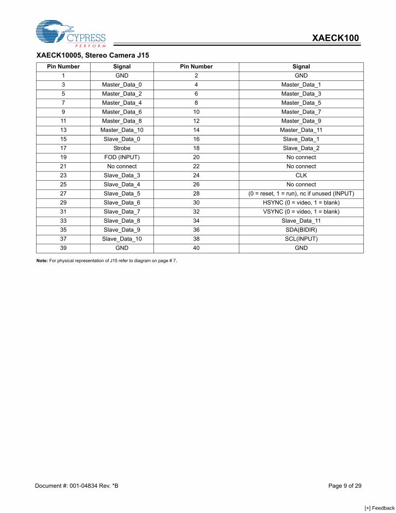
Note: For physical representation of J15 refer to diagram on page # 7.
XAECK10005, Stereo Camera J15 Pin Number Signal Pin Number Signal
1 GND 2 GND3 Master_Data_0 4 Master_Data_15 Master_Data_2 6 Master_Data_37 Master_Data_4 8 Master_Data_59 Master_Data_6 10 Master_Data_711 Master_Data_8 12 Master_Data_913 Master_Data_10 14 Master_Data_1115 Slave_Data_0 16 Slave_Data_117 Strobe 18 Slave_Data_219 FOD (INPUT) 20 No connect21 No connect 22 No connect23 Slave_Data_3 24 CLK25 Slave_Data_4 26 No connect27 Slave_Data_5 28 (0 = reset, 1 = run), nc if unused (INPUT)29 Slave_Data_6 30 HSYNC (0 = video, 1 = blank)31 Slave_Data_7 32 VSYNC (0 = video, 1 = blank)33 Slave_Data_8 34 Slave_Data_1135 Slave_Data_9 36 SDA(BIDIR)37 Slave_Data_10 38 SCL(INPUT)39 GND 40 GND
Document #: 001-04834 Rev. *B Page 9 of 29
[+] Feedback
XAECK100
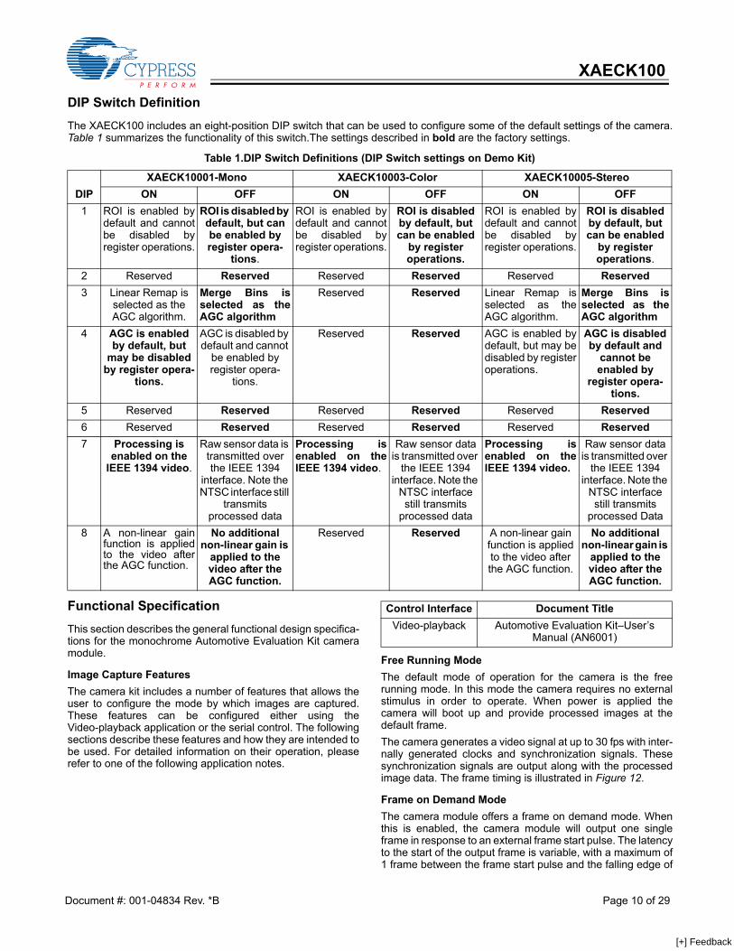
DIP Switch DefinitionThe XAECK100 includes an eight-position DIP switch that can be used to configure some of the default settings of the camera.Table 1 summarizes the functionality of this switch.The settings described in bold are the factory settings.
Functional Specification This section describes the general functional design specifica-tions for the monochrome Automotive Evaluation Kit cameramodule.
Image Capture FeaturesThe camera kit includes a number of features that allows theuser to configure the mode by which images are captured.These features can be configured either using theVideo-playback application or the serial control. The followingsections describe these features and how they are intended tobe used. For detailed information on their operation, pleaserefer to one of the following application notes.
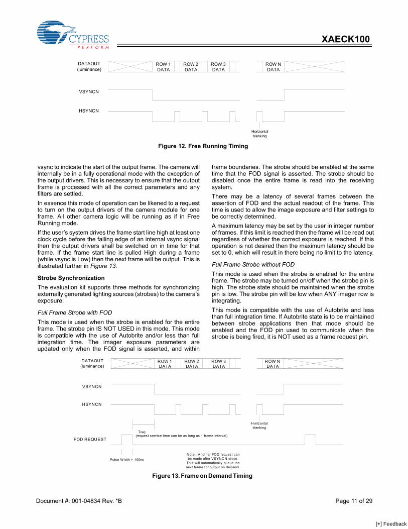
Free Running ModeThe default mode of operation for the camera is the freerunning mode. In this mode the camera requires no externalstimulus in order to operate. When power is applied thecamera will boot up and provide processed images at thedefault frame. The camera generates a video signal at up to 30 fps with inter-nally generated clocks and synchronization signals. Thesesynchronization signals are output along with the processedimage data. The frame timing is illustrated in Figure 12.
Frame on Demand Mode The camera module offers a frame on demand mode. Whenthis is enabled, the camera module will output one singleframe in response to an external frame start pulse. The latencyto the start of the output frame is variable, with a maximum of1 frame between the frame start pulse and the falling edge of
Table 1.DIP Switch Definitions (DIP Switch settings on Demo Kit)
DIPXAECK10001-Mono XAECK10003-Color XAECK10005-Stereo
ON OFF ON OFF ON OFF1 ROI is enabled by
default and cannotbe disabled byregister operations.
ROI is disabled by default, but can be enabled by register opera-
tions.
ROI is enabled bydefault and cannotbe disabled byregister operations.
ROI is disabled by default, but can be enabled
by register operations.
ROI is enabled bydefault and cannotbe disabled byregister operations.
ROI is disabled by default, but can be enabled
by register operations.
2 Reserved Reserved Reserved Reserved Reserved Reserved3 Linear Remap is
selected as the AGC algorithm.
Merge Bins isselected as theAGC algorithm
Reserved Reserved Linear Remap isselected as theAGC algorithm.
Merge Bins isselected as theAGC algorithm
4 AGC is enabled by default, but
may be disabled by register opera-
tions.
AGC is disabled by default and cannot
be enabled by register opera-
tions.
Reserved Reserved AGC is enabled bydefault, but may bedisabled by registeroperations.
AGC is disabled by default and
cannot be enabled by
register opera-tions.
5 Reserved Reserved Reserved Reserved Reserved Reserved6 Reserved Reserved Reserved Reserved Reserved Reserved7 Processing is
enabled on the IEEE 1394 video.
Raw sensor data is transmitted over the IEEE 1394
interface. Note the NTSC interface still
transmits processed data
Processing isenabled on theIEEE 1394 video.
Raw sensor data is transmitted over
the IEEE 1394 interface. Note the
NTSC interface still transmits
processed data
Processing isenabled on theIEEE 1394 video.
Raw sensor data is transmitted over
the IEEE 1394 interface. Note the
NTSC interface still transmits
processed Data8 A non-linear gain
function is appliedto the video afterthe AGC function.
No additional non-linear gain is
applied to the video after the AGC function.
Reserved Reserved A non-linear gain function is applied to the video after the AGC function.
No additional non-linear gain is
applied to the video after the AGC function.
Control Interface Document TitleVideo-playback Automotive Evaluation Kit–User’s
Manual (AN6001)
Document #: 001-04834 Rev. *B Page 10 of 29
[+] Feedback
XAECK100
vsync to indicate the start of the output frame. The camera willinternally be in a fully operational mode with the exception ofthe output drivers. This is necessary to ensure that the outputframe is processed with all the correct parameters and anyfilters are settled.In essence this mode of operation can be likened to a requestto turn on the output drivers of the camera module for oneframe. All other camera logic will be running as if in FreeRunning mode. If the user’s system drives the frame start line high at least oneclock cycle before the falling edge of an internal vsync signalthen the output drivers shall be switched on in time for thatframe. If the frame start line is pulled High during a frame(while vsync is Low) then the next frame will be output. This isillustrated further in Figure 13.
Strobe Synchronization The evaluation kit supports three methods for synchronizingexternally generated lighting sources (strobes) to the camera’sexposure:
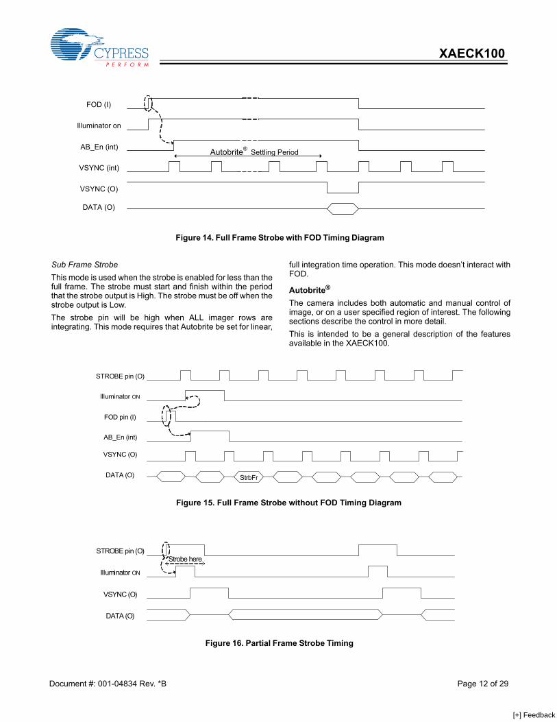
Full Frame Strobe with FODThis mode is used when the strobe is enabled for the entireframe. The strobe pin IS NOT USED in this mode. This modeis compatible with the use of Autobrite and/or less than fullintegration time. The imager exposure parameters areupdated only when the FOD signal is asserted, and within
frame boundaries. The strobe should be enabled at the sametime that the FOD signal is asserted. The strobe should bedisabled once the entire frame is read into the receivingsystem. There may be a latency of several frames between theassertion of FOD and the actual readout of the frame. Thistime is used to allow the image exposure and filter settings tobe correctly determined. A maximum latency may be set by the user in integer numberof frames. If this limit is reached then the frame will be read outregardless of whether the correct exposure is reached. If thisoperation is not desired then the maximum latency should beset to 0, which will result in there being no limit to the latency.
Full Frame Strobe without FODThis mode is used when the strobe is enabled for the entireframe. The strobe may be turned on/off when the strobe pin ishigh. The strobe state should be maintained when the strobepin is low. The strobe pin will be low when ANY imager row isintegrating. This mode is compatible with the use of Autobrite and lessthan full integration time. If Autobrite state is to be maintainedbetween strobe applications then that mode should beenabled and the FOD pin used to communicate when thestrobe is being fired, it is NOT used as a frame request pin.
VSYNCN
HSYNCN
DATAOUT(luminance)
ROW 1DATA
ROW 2DATA
ROW 3DATA
ROW NDATA
Horizontalblanking
Figure 12. Free Running Timing
Figure 13. Frame on Demand Timing
FOD REQUEST
VSYNCN
HSYNCN
DATAOUT(luminance)
ROW 1DATA
ROW 2DATA
ROW 3DATA
ROW NDATA
Pulse Width > 100ns
Treq(request service time can be as long as 1 frame interval)
Horizontalblanking
Note : Another FOD request canbe made after VSYNCN drops.
This will automatically queue thenext frame for output on demand.
Document #: 001-04834 Rev. *B Page 11 of 29
[+] Feedback
XAECK100
Sub Frame Strobe This mode is used when the strobe is enabled for less than thefull frame. The strobe must start and finish within the periodthat the strobe output is High. The strobe must be off when thestrobe output is Low. The strobe pin will be high when ALL imager rows areintegrating. This mode requires that Autobrite be set for linear,
full integration time operation. This mode doesn’t interact withFOD.
Autobrite®
The camera includes both automatic and manual control ofimage, or on a user specified region of interest. The followingsections describe the control in more detail. This is intended to be a general description of the featuresavailable in the XAECK100.
Figure 15. Full Frame Strobe without FOD Timing Diagram
STROBE pin (O)
Illuminator ON
FOD pin (I)
AB_En (int)
VSYNC (O)
DATA (O) StrbFr
Figure 14. Full Frame Strobe with FOD Timing Diagram
FOD (I)
Illuminator on
AB_En (int)
VSYNC (int)
VSYNC (O)
DATA (O)
Autobrite® Settling Period
Figure 16. Partial Frame Strobe Timing
STROBE pin (O)
Illuminator ON
VSYNC (O)
DATA (O)
Strobe here
Document #: 001-04834 Rev. *B Page 12 of 29
[+] Feedback
XAECK100
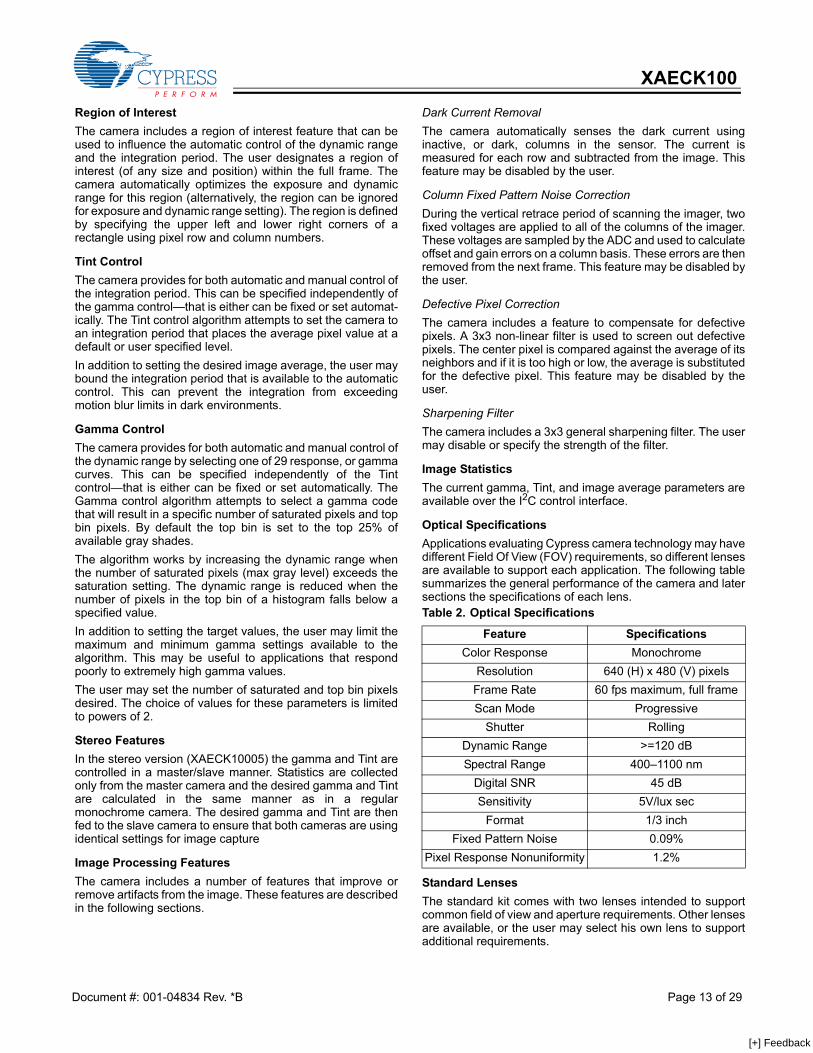
Region of Interest The camera includes a region of interest feature that can beused to influence the automatic control of the dynamic rangeand the integration period. The user designates a region ofinterest (of any size and position) within the full frame. Thecamera automatically optimizes the exposure and dynamicrange for this region (alternatively, the region can be ignoredfor exposure and dynamic range setting). The region is definedby specifying the upper left and lower right corners of arectangle using pixel row and column numbers.
Tint Control The camera provides for both automatic and manual control ofthe integration period. This can be specified independently ofthe gamma control—that is either can be fixed or set automat-ically. The Tint control algorithm attempts to set the camera toan integration period that places the average pixel value at adefault or user specified level. In addition to setting the desired image average, the user maybound the integration period that is available to the automaticcontrol. This can prevent the integration from exceedingmotion blur limits in dark environments.
Gamma Control The camera provides for both automatic and manual control ofthe dynamic range by selecting one of 29 response, or gammacurves. This can be specified independently of the Tintcontrol—that is either can be fixed or set automatically. TheGamma control algorithm attempts to select a gamma codethat will result in a specific number of saturated pixels and topbin pixels. By default the top bin is set to the top 25% ofavailable gray shades. The algorithm works by increasing the dynamic range whenthe number of saturated pixels (max gray level) exceeds thesaturation setting. The dynamic range is reduced when thenumber of pixels in the top bin of a histogram falls below aspecified value. In addition to setting the target values, the user may limit themaximum and minimum gamma settings available to thealgorithm. This may be useful to applications that respondpoorly to extremely high gamma values. The user may set the number of saturated and top bin pixelsdesired. The choice of values for these parameters is limitedto powers of 2.
Stereo Features In the stereo version (XAECK10005) the gamma and Tint arecontrolled in a master/slave manner. Statistics are collectedonly from the master camera and the desired gamma and Tintare calculated in the same manner as in a regularmonochrome camera. The desired gamma and Tint are thenfed to the slave camera to ensure that both cameras are usingidentical settings for image capture
Image Processing Features The camera includes a number of features that improve orremove artifacts from the image. These features are describedin the following sections.
Dark Current Removal The camera automatically senses the dark current usinginactive, or dark, columns in the sensor. The current ismeasured for each row and subtracted from the image. Thisfeature may be disabled by the user.
Column Fixed Pattern Noise Correction During the vertical retrace period of scanning the imager, twofixed voltages are applied to all of the columns of the imager.These voltages are sampled by the ADC and used to calculateoffset and gain errors on a column basis. These errors are thenremoved from the next frame. This feature may be disabled bythe user.
Defective Pixel Correction The camera includes a feature to compensate for defectivepixels. A 3x3 non-linear filter is used to screen out defectivepixels. The center pixel is compared against the average of itsneighbors and if it is too high or low, the average is substitutedfor the defective pixel. This feature may be disabled by theuser.
Sharpening Filter The camera includes a 3x3 general sharpening filter. The usermay disable or specify the strength of the filter.
Image Statistics The current gamma, Tint, and image average parameters areavailable over the I2C control interface.
Optical Specifications Applications evaluating Cypress camera technology may havedifferent Field Of View (FOV) requirements, so different lensesare available to support each application. The following tablesummarizes the general performance of the camera and latersections the specifications of each lens.
Standard LensesThe standard kit comes with two lenses intended to supportcommon field of view and aperture requirements. Other lensesare available, or the user may select his own lens to supportadditional requirements.
Table 2. Optical Specifications
Feature SpecificationsColor Response Monochrome
Resolution 640 (H) x 480 (V) pixelsFrame Rate 60 fps maximum, full frameScan Mode Progressive
Shutter RollingDynamic Range >=120 dBSpectral Range 400–1100 nm
Digital SNR 45 dBSensitivity 5V/lux sec
Format 1/3 inchFixed Pattern Noise 0.09%
Pixel Response Nonuniformity 1.2%
Document #: 001-04834 Rev. *B Page 13 of 29
[+] Feedback
XAECK100
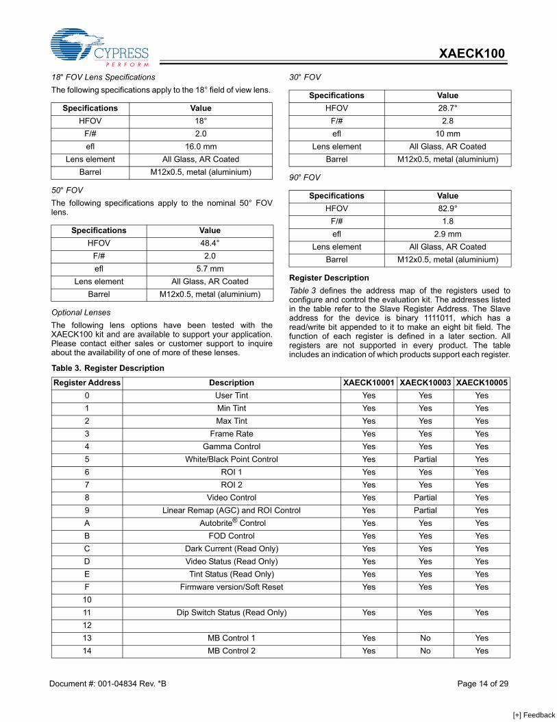
18° FOV Lens Specifications The following specifications apply to the 18° field of view lens.
50° FOV The following specifications apply to the nominal 50° FOVlens.
Optional Lenses The following lens options have been tested with theXAECK100 kit and are available to support your application.Please contact either sales or customer support to inquireabout the availability of one of more of these lenses.
30° FOV
90° FOV
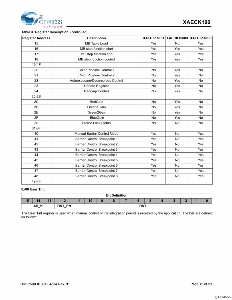
Register Description Table 3 defines the address map of the registers used toconfigure and control the evaluation kit. The addresses listedin the table refer to the Slave Register Address. The Slaveaddress for the device is binary 1111011, which has aread/write bit appended to it to make an eight bit field. Thefunction of each register is defined in a later section. Allregisters are not supported in every product. The tableincludes an indication of which products support each register.
Specifications ValueHFOV 18°
F/# 2.0efl 16.0 mm
Lens element All Glass, AR CoatedBarrel M12x0.5, metal (aluminium)
Specifications ValueHFOV 48.4°
F/# 2.0efl 5.7 mm
Lens element All Glass, AR CoatedBarrel M12x0.5, metal (aluminium)
Specifications ValueHFOV 28.7°
F/# 2.8efl 10 mm
Lens element All Glass, AR CoatedBarrel M12x0.5, metal (aluminium)
Specifications ValueHFOV 82.9°
F/# 1.8efl 2.9 mm
Lens element All Glass, AR CoatedBarrel M12x0.5, metal (aluminium)
Table 3. Register Description
Register Address Description XAECK10001 XAECK10003 XAECK100050 User Tint Yes Yes Yes1 Min Tint Yes Yes Yes2 Max Tint Yes Yes Yes3 Frame Rate Yes Yes Yes4 Gamma Control Yes Yes Yes5 White/Black Point Control Yes Partial Yes6 ROI 1 Yes Yes Yes7 ROI 2 Yes Yes Yes8 Video Control Yes Partial Yes9 Linear Remap (AGC) and ROI Control Yes Partial YesA Autobrite® Control Yes Yes YesB FOD Control Yes Yes YesC Dark Current (Read Only) Yes Yes YesD Video Status (Read Only) Yes Yes YesE Tint Status (Read Only) Yes Yes YesF Firmware version/Soft Reset Yes Yes Yes1011 Dip Switch Status (Read Only) Yes Yes Yes1213 MB Control 1 Yes No Yes14 MB Control 2 Yes No Yes
Document #: 001-04834 Rev. *B Page 14 of 29
[+] Feedback
XAECK100
The User Tint register is used when manual control of the integration period is required by the application. The bits are definedas follows:
15 MB Table Load Yes No Yes16 MB step function start Yes Yes Yes17 MB step function end Yes Yes Yes18 MB step function control Yes Yes Yes
19-1F20 Color Pipeline Control 1 No Yes No21 Color Pipeline Control 2 No Yes No22 Autoexposure/Decompress Control No Yes No23 Update Register No Yes No24 Recomp Control No Yes No
25-2B2C RedGain No Yes No2D Green1Gain No Yes No2E Green2Gain No Yes No2F BlueGain No Yes No30 Stereo Lock Status No No No
31-3F40 Manual Barrier Control Mode Yes No Yes41 Barrier Control Breakpoint 1 Yes No Yes42 Barrier Control Breakpoint 2 Yes No Yes43 Barrier Control Breakpoint 3 Yes No Yes44 Barrier Control Breakpoint 4 Yes No Yes45 Barrier Control Breakpoint 5 Yes No Yes46 Barrier Control Breakpoint 6 Yes No Yes47 Barrier Control Breakpoint 7 Yes No Yes48 Barrier Control Breakpoint 8 Yes No Yes
49-FF
Table 3. Register Description (continued)
Register Address Description XAECK10001 XAECK10003 XAECK10005
0x00 User Tint
Bit Definition15 14 13 12 11 10 9 8 7 6 5 4 3 2 1 0
AB_K TINT_EN TINT
Document #: 001-04834 Rev. *B Page 15 of 29
[+] Feedback

XAECK100
The Min Tint register is used to specify the minimum integration period available to the algorithm controlling Autobrite® as wellas controlling several other features. The bits are defined as follows:
[15:13] AB_K: This bit field can be used to slow down the response of the automatic The Integration Period is theamount of time (in row times) that the pixels accumulate light. This is basically the exposure time of theframe. The shorter the Integration Time, the darker the image will be. This may be desirable if smoothchanges between camera settings are preferable to rapid response. New Tint values are calculatedbased on the assumption that the image average will scale linearly with the Tint setting. The algorithmworks by calculating the difference between the current and target image average and then based onthat difference calculating what change in Tint is required to attain the desired image average. Thealgorithm then multiplies the change in Tint by the AB_K value and then adds the result to the currentTint value. Therefore, smaller values of AB_K will cause the Tint value to adjust in smaller increments,although the size of the steps will remain proportional to the lighting change for a fixed AB_K. The following table shows some examples of how AB_K affects the Tint calculations for a desired imageaverage of 128. (Calculated Tint = Tint(128/Image Average))
Image Average Tint
Calculated Tint
TintDifference AB_K New Tint
50 100 256 156 1 25650 100 256 156 0.5 17850 100 256 156 0.25 139
150 250 213 –37 1 213150 250 213 –37 0.5 231150 250 213 –37 0.25 241
The operation of this field is defined by the following table. Other values are not defined and should notbe used
AB_K Description4 Normal Response3 75% of Normal Speed2 50% of Normal Speed1 25% of Normal Speed
[12] TINT_EN: Writing a ‘1’ to this bit will enable manual control of the integration period. When enabled, the TINT valuespecified in this register will be used and automatic control of the integration period is disabled. Writinga ‘0’ to this location will disable manual control and enable the automatic control of the integration period.Changes to this bit will take affect on the next full frame of video.
[11:0] TINT: This field specifies the integration period as a number of rows. The maximum integration is 486 rows.At a frame rate of 30 fps, writing a value of 0X1E6 would result in a 33 ms integration period. Changesto this parameter will take affect on the next full frame of video.
0x01 Min Tint
Bit Definition15 14 13 12 11 10 9 8 7 6 5 4 3 2 1 0
TINT_SKIP MIN_TINT
[15:12] TINT_SKIP: This field specifies the frequency at which Tint updates made when automatic control of Tint is enabled.This field is set to a 2 frames by default to accommodate the one frame latency between calculation ofa new Tint value and its taking effect. Note that the Tint will settle in the same number and size of steps,but will take longer to settle. To change the size of steps that Tint will use to adjust, use the AB_Kparameter.
[11:0] MIN_TINT: This field is used to specify the minimum integration period that the Autobrite® algorithm will use tocontrol the camera. It is only valid when manual control of the integration period is disabled. It is specifiedas the number of row periods you wish to have the sensor integrate. The maximum integration is 486rows. Changes to this parameter will take affect on the next full frame of video.
Document #: 001-04834 Rev. *B Page 16 of 29
[+] Feedback
XAECK100
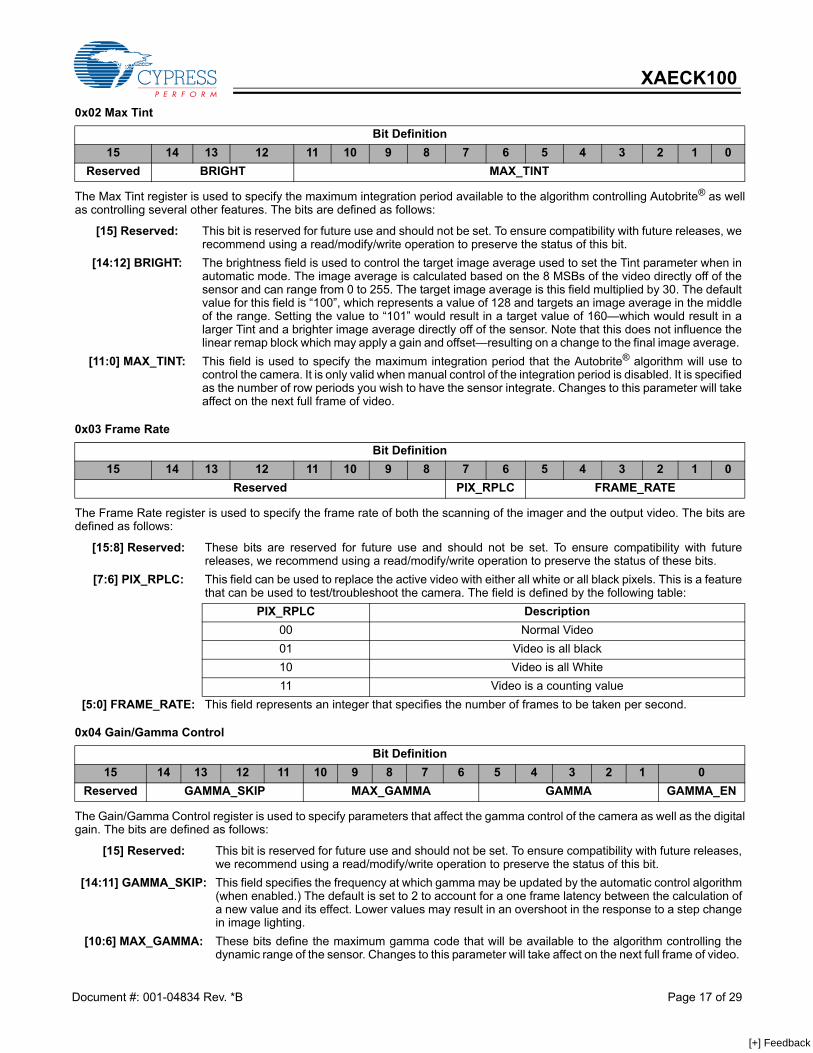
The Max Tint register is used to specify the maximum integration period available to the algorithm controlling Autobrite® as wellas controlling several other features. The bits are defined as follows:
The Frame Rate register is used to specify the frame rate of both the scanning of the imager and the output video. The bits aredefined as follows:
The Gain/Gamma Control register is used to specify parameters that affect the gamma control of the camera as well as the digitalgain. The bits are defined as follows:
0x02 Max Tint
Bit Definition15 14 13 12 11 10 9 8 7 6 5 4 3 2 1 0
Reserved BRIGHT MAX_TINT
[15] Reserved: This bit is reserved for future use and should not be set. To ensure compatibility with future releases, werecommend using a read/modify/write operation to preserve the status of this bit.
[14:12] BRIGHT: The brightness field is used to control the target image average used to set the Tint parameter when inautomatic mode. The image average is calculated based on the 8 MSBs of the video directly off of thesensor and can range from 0 to 255. The target image average is this field multiplied by 30. The defaultvalue for this field is “100”, which represents a value of 128 and targets an image average in the middleof the range. Setting the value to “101” would result in a target value of 160—which would result in alarger Tint and a brighter image average directly off of the sensor. Note that this does not influence thelinear remap block which may apply a gain and offset—resulting on a change to the final image average.
[11:0] MAX_TINT: This field is used to specify the maximum integration period that the Autobrite® algorithm will use tocontrol the camera. It is only valid when manual control of the integration period is disabled. It is specifiedas the number of row periods you wish to have the sensor integrate. Changes to this parameter will takeaffect on the next full frame of video.
0x03 Frame Rate
Bit Definition15 14 13 12 11 10 9 8 7 6 5 4 3 2 1 0
Reserved PIX_RPLC FRAME_RATE
[15:8] Reserved: These bits are reserved for future use and should not be set. To ensure compatibility with futurereleases, we recommend using a read/modify/write operation to preserve the status of these bits.
[7:6] PIX_RPLC: This field can be used to replace the active video with either all white or all black pixels. This is a featurethat can be used to test/troubleshoot the camera. The field is defined by the following table:
PIX_RPLC Description00 Normal Video01 Video is all black10 Video is all White11 Video is a counting value
[5:0] FRAME_RATE: This field represents an integer that specifies the number of frames to be taken per second.
0x04 Gain/Gamma Control
Bit Definition15 14 13 12 11 10 9 8 7 6 5 4 3 2 1 0
Reserved GAMMA_SKIP MAX_GAMMA GAMMA GAMMA_EN
[15] Reserved: This bit is reserved for future use and should not be set. To ensure compatibility with future releases,we recommend using a read/modify/write operation to preserve the status of this bit.
[14:11] GAMMA_SKIP: This field specifies the frequency at which gamma may be updated by the automatic control algorithm(when enabled.) The default is set to 2 to account for a one frame latency between the calculation ofa new value and its effect. Lower values may result in an overshoot in the response to a step changein image lighting.
[10:6] MAX_GAMMA: These bits define the maximum gamma code that will be available to the algorithm controlling thedynamic range of the sensor. Changes to this parameter will take affect on the next full frame of video.
Document #: 001-04834 Rev. *B Page 17 of 29
[+] Feedback
XAECK100
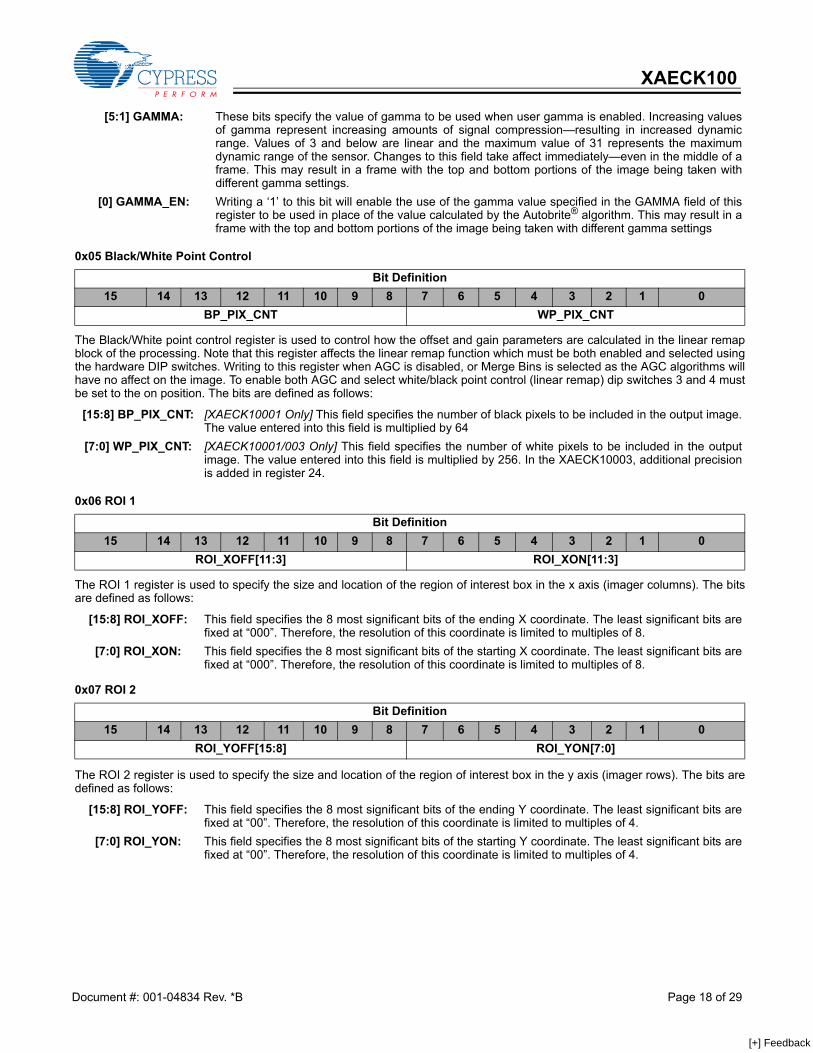
The Black/White point control register is used to control how the offset and gain parameters are calculated in the linear remapblock of the processing. Note that this register affects the linear remap function which must be both enabled and selected usingthe hardware DIP switches. Writing to this register when AGC is disabled, or Merge Bins is selected as the AGC algorithms willhave no affect on the image. To enable both AGC and select white/black point control (linear remap) dip switches 3 and 4 mustbe set to the on position. The bits are defined as follows:
The ROI 1 register is used to specify the size and location of the region of interest box in the x axis (imager columns). The bitsare defined as follows:
The ROI 2 register is used to specify the size and location of the region of interest box in the y axis (imager rows). The bits aredefined as follows:
[5:1] GAMMA: These bits specify the value of gamma to be used when user gamma is enabled. Increasing valuesof gamma represent increasing amounts of signal compression—resulting in increased dynamicrange. Values of 3 and below are linear and the maximum value of 31 represents the maximumdynamic range of the sensor. Changes to this field take affect immediately—even in the middle of aframe. This may result in a frame with the top and bottom portions of the image being taken withdifferent gamma settings.
[0] GAMMA_EN: Writing a ‘1’ to this bit will enable the use of the gamma value specified in the GAMMA field of thisregister to be used in place of the value calculated by the Autobrite® algorithm. This may result in aframe with the top and bottom portions of the image being taken with different gamma settings
0x05 Black/White Point Control
Bit Definition15 14 13 12 11 10 9 8 7 6 5 4 3 2 1 0
BP_PIX_CNT WP_PIX_CNT
[15:8] BP_PIX_CNT: [XAECK10001 Only] This field specifies the number of black pixels to be included in the output image.The value entered into this field is multiplied by 64
[7:0] WP_PIX_CNT: [XAECK10001/003 Only] This field specifies the number of white pixels to be included in the outputimage. The value entered into this field is multiplied by 256. In the XAECK10003, additional precisionis added in register 24.
0x06 ROI 1
Bit Definition15 14 13 12 11 10 9 8 7 6 5 4 3 2 1 0
ROI_XOFF[11:3] ROI_XON[11:3]
[15:8] ROI_XOFF: This field specifies the 8 most significant bits of the ending X coordinate. The least significant bits arefixed at “000”. Therefore, the resolution of this coordinate is limited to multiples of 8.
[7:0] ROI_XON: This field specifies the 8 most significant bits of the starting X coordinate. The least significant bits arefixed at “000”. Therefore, the resolution of this coordinate is limited to multiples of 8.
0x07 ROI 2
Bit Definition15 14 13 12 11 10 9 8 7 6 5 4 3 2 1 0
ROI_YOFF[15:8] ROI_YON[7:0]
[15:8] ROI_YOFF: This field specifies the 8 most significant bits of the ending Y coordinate. The least significant bits arefixed at “00”. Therefore, the resolution of this coordinate is limited to multiples of 4.
[7:0] ROI_YON: This field specifies the 8 most significant bits of the starting Y coordinate. The least significant bits arefixed at “00”. Therefore, the resolution of this coordinate is limited to multiples of 4.
Document #: 001-04834 Rev. *B Page 18 of 29
[+] Feedback

XAECK100
The Video control register is used to configure and enable various features of the camera control algorithms.
0x08 Video Control
Bit Definition15 14 13 12 11 10 9 8 7 6 5 4 3 2 1 0
CFG
_RO
W0_EN
TINT_H
YST
STALL_A
B_D
ISAB
LE
DA
RK
_OFFSET_EN
SHA
RP_STR
ENG
TH
SHA
RP_EN
FPN_G
AIN
_EN
FPN_O
FFSET_EN
FULL_FR
AM
E_FPN
AG
C_M
OD
E
WP_EN
BP_EN
SK_EN
INVR
T_SYNC
NTSC
_TEST_ENA
BLE
Reserved
[15] CFG_ROW0_EN: Writing a ‘1’ to this location enables configuration data to be used in place of the first row of dataon the IEEE 1394 video output. This contains a variety of information about the capture param-eters and processing behavior and tags each frame with it.
[14] TINT_HYST: Writing a ‘1’ to this bit will cause the automatic control of the Tint settings to have additionalhysteresis. This added hysteresis will cause changes of less than one line to be suppressed. Thisis useful in eliminating the appearance of flickering in very bright scenes where a change of oneline of integration time represents a significant change in image brightness.
[13] STALL_AB_DISABLE: Writing a ‘1’ to this location will cause the Autobrite control parameters to be fixed during theframes that are not enabled for transmission.
[12] DARK_OFFSET_EN: Writing a ‘1’ to this location will enable dark current correction. Writing a ‘0’ will disable darkcurrent correction.
[11] SHARP_STRENGTH: Writing a ‘1’ to this bit will cause the sharpening filter to be at the stronger setting. Writing a ‘0’ tothis bit will cause the sharpening filter to be at a weaker setting.
[10] SHARP_EN: Writing a ‘1’ to this bit will enable the 3x3 FIR sharpening filter. This filter has two strengths. [9] FPN_GAIN_EN: Writing a ‘1’ to this location will enable the automatic correction of column fixed pattern gain errors
in the hardware. FPN coefficients are calculated by placing known voltages on the columns whenimager data is not being read. Writing a ‘0’ to this location will disable FPN gain correction. Notethat on power-up or after a system reset, this may require as much as two minutes to reach fullperformance. This is a result of filtering on the correction values to remove the affects of non-fixedpattern noise.
[8] FPN_OFFSET_EN: Writing a ‘1’ to this location will enable the automatic correction of column fixed pattern offseterrors in the hardware. FPN coefficients are calculated by placing known voltages on the columnswhen imager data is not being read. Writing a ‘0’ to this location will disable FPN offset correction.Note that on power up or after a system reset, this may require as much as two minutes to reachfull performance. This is a result of filtering on the correction values to remove the affects ofnon-fixed pattern noise.
[7] FULL_FRAME_FPN: Writing a ‘1’ to this location will cause FPN data to be collected over the entire frame. This is atest feature and it will cause the video to be overwritten. Writing a ‘0’ to this bit will enable normaloperation.
[6] AGC_MODE: Writing a ‘0’ to this bit will disable all gain stages in the processing pipeline including linear remapand user gain. This mode is intended to be used to measure the SNR of the imager. Writing a ‘1’to this bit will enable normal operation of the processing pipeline.
[5] WP_EN: [XAECK10001 with Linear Remap Only] Writing a ‘1’ to this bit will enable the linear remap (orAGC) block in the processing pipeline. This block adds gain to the digital signal to ensure thatthe target number of pixels is at a saturated value. Writing a ‘0’ to this bit will disable the block.
[4] BP_EN: [XAECK10001 with Linear Remap Only] Writing a ‘1’ to this bit will enable black point correctionin the linear remap (or AGC) block in the processing pipeline. This feature subtracts and offsetfrom the pixel value in order to ensure that a target number of pixels is at a value of zero. WP_ENmust be set in order for this feature to be active.
[3] SK_EN: Writing a ‘1’ to this location will enable the starkiller, non-linear filter. This filter detects and correctsfor single pixel defects in the imager.
Document #: 001-04834 Rev. *B Page 19 of 29
[+] Feedback
XAECK100
[XAECK100 Only] The Linear Remap Control register provides control over the Automatic Gain Control (AGC) block in the pixelprocessing pipeline. The block provides for both black level and white level correction and can be based either on the entire imageor on a region of interest. Note that this register only functions if AGC is enabled and linear remap is selected using the hardwareDIP switches. The bits are defined as follows:
The Autobrite Control register is used to specify parameters that influence the automatic selection of a gamma code (dynamicrange control.) The bits are defined as follows:
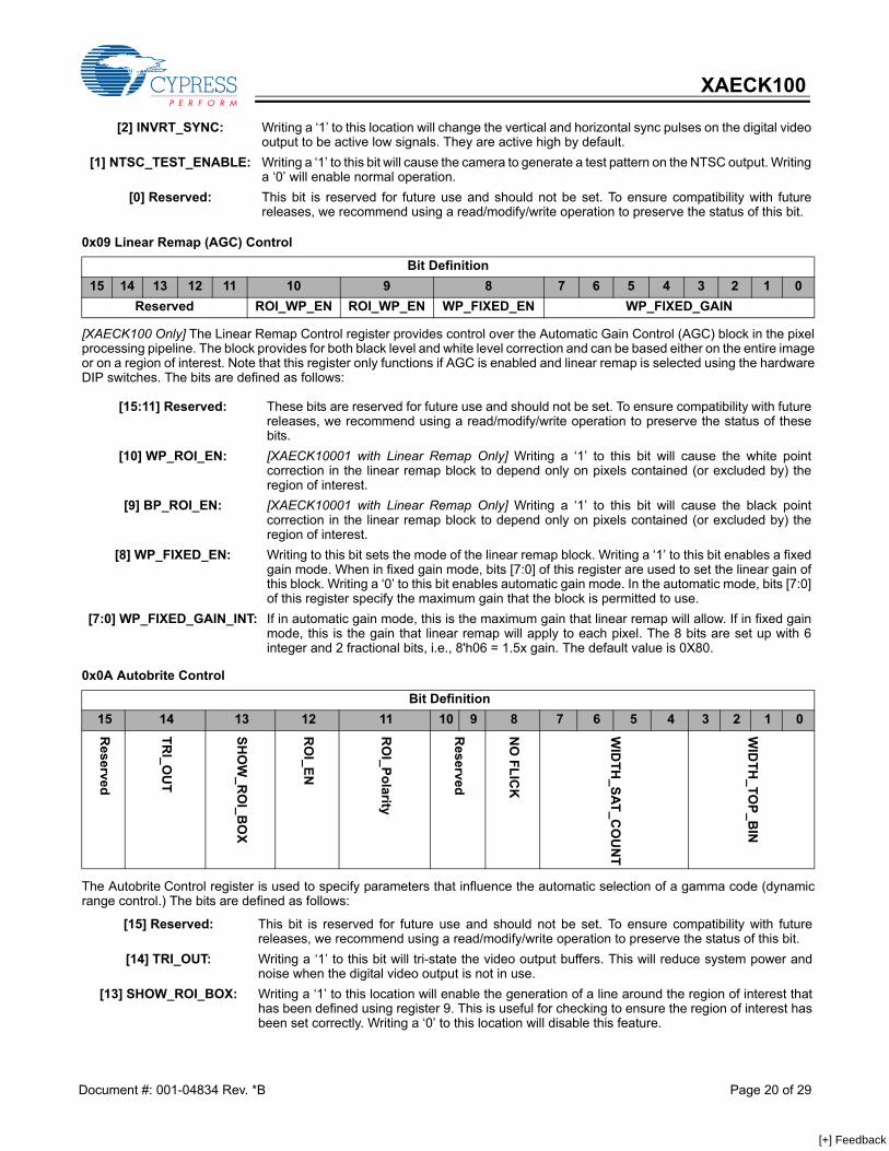
[2] INVRT_SYNC: Writing a ‘1’ to this location will change the vertical and horizontal sync pulses on the digital videooutput to be active low signals. They are active high by default.
[1] NTSC_TEST_ENABLE: Writing a ‘1’ to this bit will cause the camera to generate a test pattern on the NTSC output. Writinga ‘0’ will enable normal operation.
[0] Reserved: This bit is reserved for future use and should not be set. To ensure compatibility with futurereleases, we recommend using a read/modify/write operation to preserve the status of this bit.
0x09 Linear Remap (AGC) Control
Bit Definition15 14 13 12 11 10 9 8 7 6 5 4 3 2 1 0
Reserved ROI_WP_EN ROI_WP_EN WP_FIXED_EN WP_FIXED_GAIN
[15:11] Reserved: These bits are reserved for future use and should not be set. To ensure compatibility with futurereleases, we recommend using a read/modify/write operation to preserve the status of thesebits.
[10] WP_ROI_EN: [XAECK10001 with Linear Remap Only] Writing a ‘1’ to this bit will cause the white pointcorrection in the linear remap block to depend only on pixels contained (or excluded by) theregion of interest.
[9] BP_ROI_EN: [XAECK10001 with Linear Remap Only] Writing a ‘1’ to this bit will cause the black pointcorrection in the linear remap block to depend only on pixels contained (or excluded by) theregion of interest.
[8] WP_FIXED_EN: Writing to this bit sets the mode of the linear remap block. Writing a ‘1’ to this bit enables a fixedgain mode. When in fixed gain mode, bits [7:0] of this register are used to set the linear gain ofthis block. Writing a ‘0’ to this bit enables automatic gain mode. In the automatic mode, bits [7:0]of this register specify the maximum gain that the block is permitted to use.
[7:0] WP_FIXED_GAIN_INT: If in automatic gain mode, this is the maximum gain that linear remap will allow. If in fixed gainmode, this is the gain that linear remap will apply to each pixel. The 8 bits are set up with 6integer and 2 fractional bits, i.e., 8'h06 = 1.5x gain. The default value is 0X80.
0x0A Autobrite Control
Bit Definition15 14 13 12 11 10 9 8 7 6 5 4 3 2 1 0
Reserved
TRI_O
UT
SHO
W_R
OI_B
OX
RO
I_EN
RO
I_Polarity
Reserved
NO
FLICK
WID
TH_SAT_C
OU
NT
WID
TH_TO
P_BIN
[15] Reserved: This bit is reserved for future use and should not be set. To ensure compatibility with futurereleases, we recommend using a read/modify/write operation to preserve the status of this bit.
[14] TRI_OUT: Writing a ‘1’ to this bit will tri-state the video output buffers. This will reduce system power andnoise when the digital video output is not in use.
[13] SHOW_ROI_BOX: Writing a ‘1’ to this location will enable the generation of a line around the region of interest thathas been defined using register 9. This is useful for checking to ensure the region of interest hasbeen set correctly. Writing a ‘0’ to this location will disable this feature.
Document #: 001-04834 Rev. *B Page 20 of 29
[+] Feedback
XAECK100
The FOD Control register is used to specify the frame on demand mode desired for the application.
The Dark Current register can be used to read back the average dark current correction value. The bits are defined as follows:
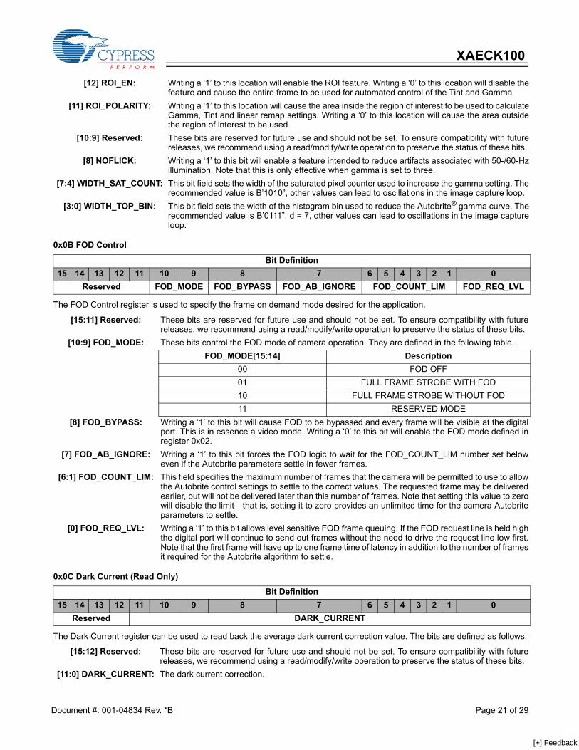
[12] ROI_EN: Writing a ‘1’ to this location will enable the ROI feature. Writing a ‘0’ to this location will disable thefeature and cause the entire frame to be used for automated control of the Tint and Gamma
[11] ROI_POLARITY: Writing a ‘1’ to this location will cause the area inside the region of interest to be used to calculateGamma, Tint and linear remap settings. Writing a ‘0’ to this location will cause the area outsidethe region of interest to be used.
[10:9] Reserved: These bits are reserved for future use and should not be set. To ensure compatibility with futurereleases, we recommend using a read/modify/write operation to preserve the status of these bits.
[8] NOFLICK: Writing a ‘1’ to this bit will enable a feature intended to reduce artifacts associated with 50-/60-Hzillumination. Note that this is only effective when gamma is set to three.
[7:4] WIDTH_SAT_COUNT: This bit field sets the width of the saturated pixel counter used to increase the gamma setting. Therecommended value is B’1010”, other values can lead to oscillations in the image capture loop.
[3:0] WIDTH_TOP_BIN: This bit field sets the width of the histogram bin used to reduce the Autobrite® gamma curve. Therecommended value is B’0111”, d = 7, other values can lead to oscillations in the image captureloop.
0x0B FOD Control
Bit Definition15 14 13 12 11 10 9 8 7 6 5 4 3 2 1 0
Reserved FOD_MODE FOD_BYPASS FOD_AB_IGNORE FOD_COUNT_LIM FOD_REQ_LVL
[15:11] Reserved: These bits are reserved for future use and should not be set. To ensure compatibility with futurereleases, we recommend using a read/modify/write operation to preserve the status of these bits.
[10:9] FOD_MODE: These bits control the FOD mode of camera operation. They are defined in the following table.FOD_MODE[15:14] Description
00 FOD OFF01 FULL FRAME STROBE WITH FOD10 FULL FRAME STROBE WITHOUT FOD11 RESERVED MODE
[8] FOD_BYPASS: Writing a ‘1’ to this bit will cause FOD to be bypassed and every frame will be visible at the digitalport. This is in essence a video mode. Writing a ‘0’ to this bit will enable the FOD mode defined inregister 0x02.
[7] FOD_AB_IGNORE: Writing a ‘1’ to this bit forces the FOD logic to wait for the FOD_COUNT_LIM number set beloweven if the Autobrite parameters settle in fewer frames.
[6:1] FOD_COUNT_LIM: This field specifies the maximum number of frames that the camera will be permitted to use to allowthe Autobrite control settings to settle to the correct values. The requested frame may be deliveredearlier, but will not be delivered later than this number of frames. Note that setting this value to zerowill disable the limit—that is, setting it to zero provides an unlimited time for the camera Autobriteparameters to settle.
[0] FOD_REQ_LVL: Writing a ‘1’ to this bit allows level sensitive FOD frame queuing. If the FOD request line is held highthe digital port will continue to send out frames without the need to drive the request line low first.Note that the first frame will have up to one frame time of latency in addition to the number of framesit required for the Autobrite algorithm to settle.
0x0C Dark Current (Read Only)
Bit Definition15 14 13 12 11 10 9 8 7 6 5 4 3 2 1 0
Reserved DARK_CURRENT
[15:12] Reserved: These bits are reserved for future use and should not be set. To ensure compatibility with futurereleases, we recommend using a read/modify/write operation to preserve the status of these bits.
[11:0] DARK_CURRENT: The dark current correction.
Document #: 001-04834 Rev. *B Page 21 of 29
[+] Feedback
XAECK100
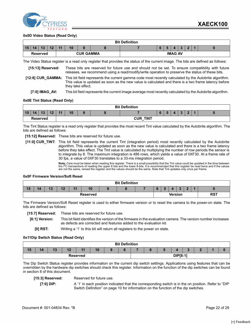
The Video Status register is a read only register that provides the status of the current image. The bits are defined as follows:
The Tint Status register is a read only register that provides the most recent Tint value calculated by the Autobrite algorithm. Thebits are defined as follows:
The Firmware Version/Soft Reset register is used to either firmware version or to reset the camera to the power-on state. Thebits are defined as follows:
The Dip Switch Status register provides information on the current dip switch settings. Applications using features that can beoverridden by the hardware dip switches should check this register. Information on the function of the dip switches can be foundin section 8 of this document.
0x0D Video Status (Read Only)
Bit Definition15 14 13 12 11 10 9 8 7 6 5 4 3 2 1 0
Reserved CUR GAMMA IMAG AV
[15:13] Reserved: These bits are reserved for future use and should not be set. To ensure compatibility with futurereleases, we recommend using a read/modify/write operation to preserve the status of these bits.
[12:8] CUR_GAMMA: This bit field represents the current gamma code most recently calculated by the Autobrite algorithm.This value is updated as soon as the new value is calculated and there is a two frame latency beforethey take effect.
[7:0] IMAG_AV: This bit field represents the current image average most recently calculated by the Autobrite algorithm.
0x0E Tint Status (Read Only)
Bit Definition15 14 13 12 11 10 9 8 7 6 5 4 3 2 1 0
Reserved CUR_TINT
[15:12] Reserved: These bits are reserved for future use.[11:0] CUR_TINT: This bit field represents the current Tint (integration period) most recently calculated by the Autobrite
algorithm. This value is updated as soon as the new value is calculated and there is a two frame latencybefore they take effect. The Tint value is calculated by multiplying the number of row periods the sensor isto integrate by 8. The maximum integration is 486 rows, which yields a value of 0XF30. At a frame rate of30 fps, a value of 0XF30 translates to a 33-ms integration period. Note: Care must be taken when reading this register. There is a small possibility that the Tint value could be updated in the time betweenthe I2C transactions of reading the upper 8 bits and the lower 8-bits. It is recommended that this register be read twice and if the valuesare not the same, reread the register and the values should be the same. Note that Tint updates only once per frame.
0x0F Firmware Version/Soft Reset
Bit Definition15 14 13 12 11 10 9 8 7 6 5 4 3 2 1 0
Reserved Version RST
[15:7] Reserved: These bits are reserved for future use.[6:1] Version: This bit field identifies the version of the firmware in the evaluation camera. The version number increases
as defects are corrected and features added to the evaluation kit. [0] RST: Writing a ‘1’ to this bit will return all registers to the power on state.
0x11Dip Switch Status (Read Only)
Bit Definition15 14 13 12 11 10 9 8 7 6 5 4 3 2 1 0
Reserved DIP[8:1]
[15:3] Reserved: Reserved for future use.[7:0] DIP: A ‘1’ in each position indicated that the corresponding switch is in the on position. Refer to “DIP
Switch Definition” on page 10 for information on the function of the dip switches.
Document #: 001-04834 Rev. *B Page 22 of 29
[+] Feedback
XAECK100
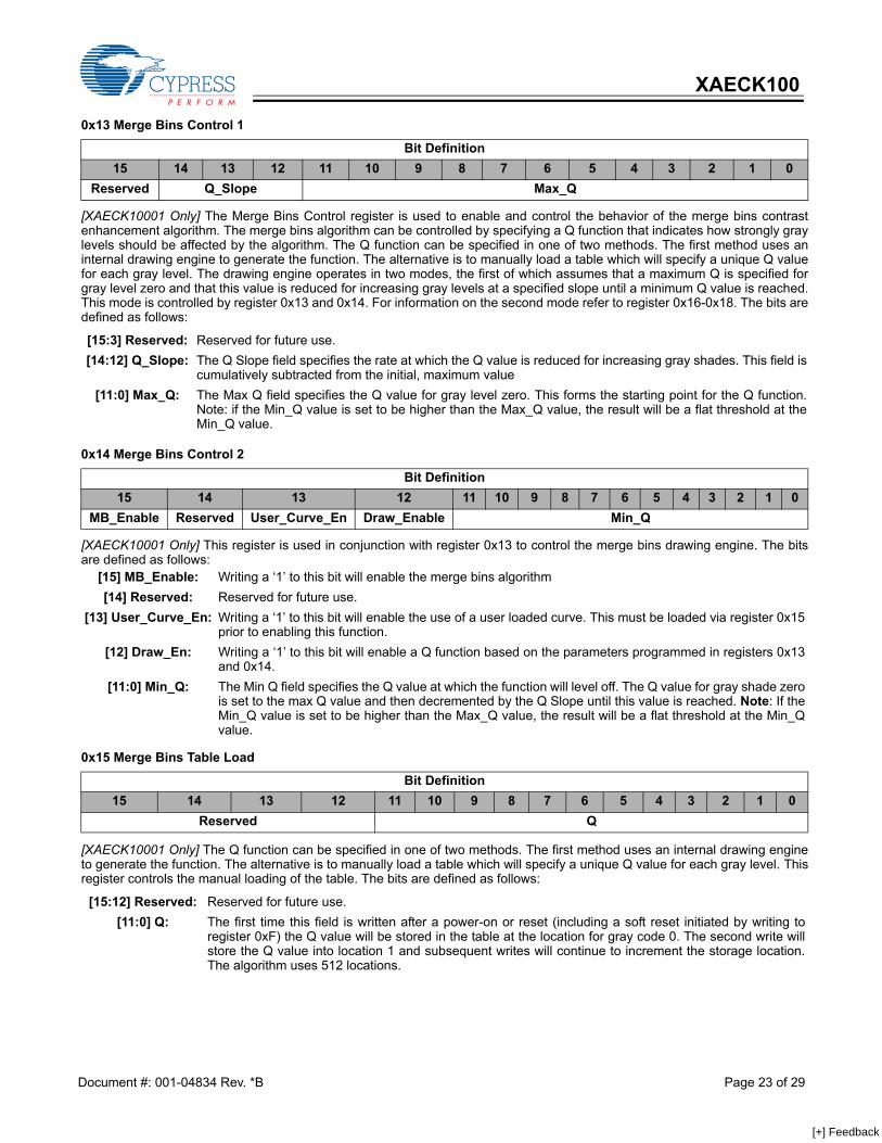
[XAECK10001 Only] The Merge Bins Control register is used to enable and control the behavior of the merge bins contrastenhancement algorithm. The merge bins algorithm can be controlled by specifying a Q function that indicates how strongly graylevels should be affected by the algorithm. The Q function can be specified in one of two methods. The first method uses aninternal drawing engine to generate the function. The alternative is to manually load a table which will specify a unique Q valuefor each gray level. The drawing engine operates in two modes, the first of which assumes that a maximum Q is specified forgray level zero and that this value is reduced for increasing gray levels at a specified slope until a minimum Q value is reached.This mode is controlled by register 0x13 and 0x14. For information on the second mode refer to register 0x16-0x18. The bits aredefined as follows:
[XAECK10001 Only] This register is used in conjunction with register 0x13 to control the merge bins drawing engine. The bitsare defined as follows:
[XAECK10001 Only] The Q function can be specified in one of two methods. The first method uses an internal drawing engineto generate the function. The alternative is to manually load a table which will specify a unique Q value for each gray level. Thisregister controls the manual loading of the table. The bits are defined as follows:
0x13 Merge Bins Control 1
Bit Definition15 14 13 12 11 10 9 8 7 6 5 4 3 2 1 0
Reserved Q_Slope Max_Q
[15:3] Reserved: Reserved for future use.[14:12] Q_Slope: The Q Slope field specifies the rate at which the Q value is reduced for increasing gray shades. This field is
cumulatively subtracted from the initial, maximum value [11:0] Max_Q: The Max Q field specifies the Q value for gray level zero. This forms the starting point for the Q function.
Note: if the Min_Q value is set to be higher than the Max_Q value, the result will be a flat threshold at theMin_Q value.
0x14 Merge Bins Control 2
Bit Definition15 14 13 12 11 10 9 8 7 6 5 4 3 2 1 0
MB_Enable Reserved User_Curve_En Draw_Enable Min_Q
[15] MB_Enable: Writing a ‘1’ to this bit will enable the merge bins algorithm [14] Reserved: Reserved for future use.
[13] User_Curve_En: Writing a ‘1’ to this bit will enable the use of a user loaded curve. This must be loaded via register 0x15prior to enabling this function.
[12] Draw_En: Writing a ‘1’ to this bit will enable a Q function based on the parameters programmed in registers 0x13and 0x14.
[11:0] Min_Q: The Min Q field specifies the Q value at which the function will level off. The Q value for gray shade zerois set to the max Q value and then decremented by the Q Slope until this value is reached. Note: If theMin_Q value is set to be higher than the Max_Q value, the result will be a flat threshold at the Min_Qvalue.
0x15 Merge Bins Table Load
Bit Definition15 14 13 12 11 10 9 8 7 6 5 4 3 2 1 0
Reserved Q
[15:12] Reserved: Reserved for future use. [11:0] Q: The first time this field is written after a power-on or reset (including a soft reset initiated by writing to
register 0xF) the Q value will be stored in the table at the location for gray code 0. The second write willstore the Q value into location 1 and subsequent writes will continue to increment the storage location.The algorithm uses 512 locations.
Document #: 001-04834 Rev. *B Page 23 of 29
[+] Feedback
XAECK100
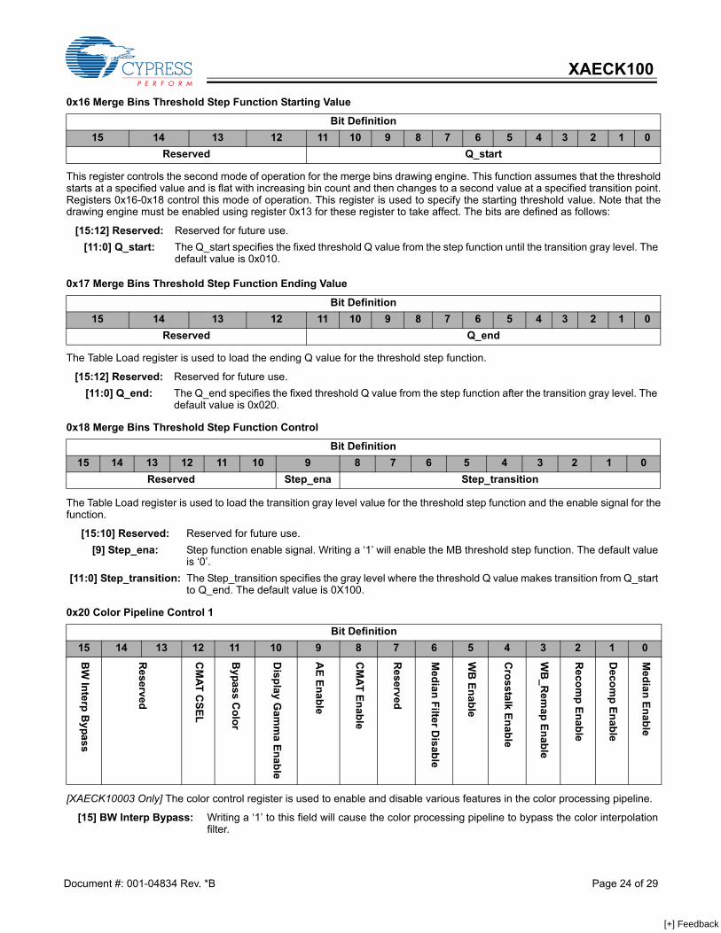
This register controls the second mode of operation for the merge bins drawing engine. This function assumes that the thresholdstarts at a specified value and is flat with increasing bin count and then changes to a second value at a specified transition point.Registers 0x16-0x18 control this mode of operation. This register is used to specify the starting threshold value. Note that thedrawing engine must be enabled using register 0x13 for these register to take affect. The bits are defined as follows:
The Table Load register is used to load the ending Q value for the threshold step function.
The Table Load register is used to load the transition gray level value for the threshold step function and the enable signal for thefunction.
[XAECK10003 Only] The color control register is used to enable and disable various features in the color processing pipeline.
0x16 Merge Bins Threshold Step Function Starting Value
Bit Definition15 14 13 12 11 10 9 8 7 6 5 4 3 2 1 0
Reserved Q_start
[15:12] Reserved: Reserved for future use. [11:0] Q_start: The Q_start specifies the fixed threshold Q value from the step function until the transition gray level. The
default value is 0x010.
0x17 Merge Bins Threshold Step Function Ending Value
Bit Definition15 14 13 12 11 10 9 8 7 6 5 4 3 2 1 0
Reserved Q_end
[15:12] Reserved: Reserved for future use. [11:0] Q_end: The Q_end specifies the fixed threshold Q value from the step function after the transition gray level. The
default value is 0x020.
0x18 Merge Bins Threshold Step Function Control
Bit Definition15 14 13 12 11 10 9 8 7 6 5 4 3 2 1 0
Reserved Step_ena Step_transition
[15:10] Reserved: Reserved for future use. [9] Step_ena: Step function enable signal. Writing a ‘1’ will enable the MB threshold step function. The default value
is ‘0’. [11:0] Step_transition: The Step_transition specifies the gray level where the threshold Q value makes transition from Q_start
to Q_end. The default value is 0X100.
0x20 Color Pipeline Control 1
Bit Definition15 14 13 12 11 10 9 8 7 6 5 4 3 2 1 0
BW
Interp Bypass
Reserved
CM
AT CSEL
Bypass C
olor
Display G
amm
a Enable
AE Enable
CM
AT Enable
Reserved
Median Filter D
isable
WB
Enable
Crosstalk Enable
WB
_Rem
ap Enable
Recom
p Enable
Decom
p Enable
Median Enable
[15] BW Interp Bypass: Writing a ‘1’ to this field will cause the color processing pipeline to bypass the color interpolationfilter.
Document #: 001-04834 Rev. *B Page 24 of 29
[+] Feedback
XAECK100
[XAECK10003 Only] The color control register is used to enable and disable various features in the color processing pipeline.
[XAECK10003 Only] The Autoexposure/Decompress control register allows the used to specify autoexposure and decompressgamma curves.
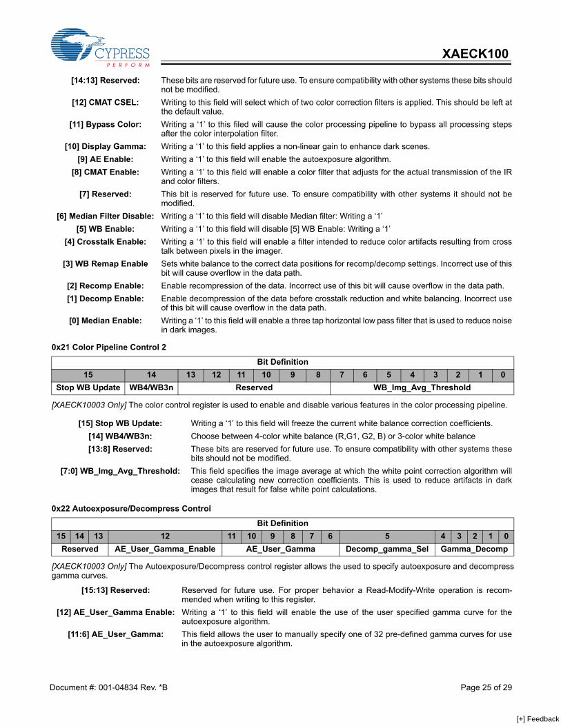
[14:13] Reserved: These bits are reserved for future use. To ensure compatibility with other systems these bits shouldnot be modified.
[12] CMAT CSEL: Writing to this field will select which of two color correction filters is applied. This should be left atthe default value.
[11] Bypass Color: Writing a ‘1’ to this filed will cause the color processing pipeline to bypass all processing stepsafter the color interpolation filter.
[10] Display Gamma: Writing a ‘1’ to this field applies a non-linear gain to enhance dark scenes. [9] AE Enable: Writing a ‘1’ to this field will enable the autoexposure algorithm.
[8] CMAT Enable: Writing a ‘1’ to this field will enable a color filter that adjusts for the actual transmission of the IRand color filters.
[7] Reserved: This bit is reserved for future use. To ensure compatibility with other systems it should not bemodified.
[6] Median Filter Disable: Writing a ‘1’ to this field will disable Median filter: Writing a ‘1’ [5] WB Enable: Writing a ‘1’ to this field will disable [5] WB Enable: Writing a ‘1’
[4] Crosstalk Enable: Writing a ‘1’ to this field will enable a filter intended to reduce color artifacts resulting from crosstalk between pixels in the imager.
[3] WB Remap Enable Sets white balance to the correct data positions for recomp/decomp settings. Incorrect use of thisbit will cause overflow in the data path.
[2] Recomp Enable: Enable recompression of the data. Incorrect use of this bit will cause overflow in the data path. [1] Decomp Enable: Enable decompression of the data before crosstalk reduction and white balancing. Incorrect use
of this bit will cause overflow in the data path. [0] Median Enable: Writing a ‘1’ to this field will enable a three tap horizontal low pass filter that is used to reduce noise
in dark images.
0x21 Color Pipeline Control 2
Bit Definition15 14 13 12 11 10 9 8 7 6 5 4 3 2 1 0
Stop WB Update WB4/WB3n Reserved WB_Img_Avg_Threshold
[15] Stop WB Update: Writing a ‘1’ to this field will freeze the current white balance correction coefficients. [14] WB4/WB3n: Choose between 4-color white balance (R,G1, G2, B) or 3-color white balance [13:8] Reserved: These bits are reserved for future use. To ensure compatibility with other systems these
bits should not be modified. [7:0] WB_Img_Avg_Threshold: This field specifies the image average at which the white point correction algorithm will
cease calculating new correction coefficients. This is used to reduce artifacts in darkimages that result for false white point calculations.
0x22 Autoexposure/Decompress Control
Bit Definition15 14 13 12 11 10 9 8 7 6 5 4 3 2 1 0
Reserved AE_User_Gamma_Enable AE_User_Gamma Decomp_gamma_Sel Gamma_Decomp
[15:13] Reserved: Reserved for future use. For proper behavior a Read-Modify-Write operation is recom-mended when writing to this register.
[12] AE_User_Gamma Enable: Writing a ‘1’ to this field will enable the use of the user specified gamma curve for theautoexposure algorithm.
[11:6] AE_User_Gamma: This field allows the user to manually specify one of 32 pre-defined gamma curves for usein the autoexposure algorithm.
Document #: 001-04834 Rev. *B Page 25 of 29
[+] Feedback
XAECK100
[XAECK10003 Only] The update register is used to force an update of the Automatic White Balance coefficients. Typically this isonly used when White Balance has been frozen using register 0x20.
[XAECK10003 Only] The recomp color register controls the recompression of the pixel after processing.
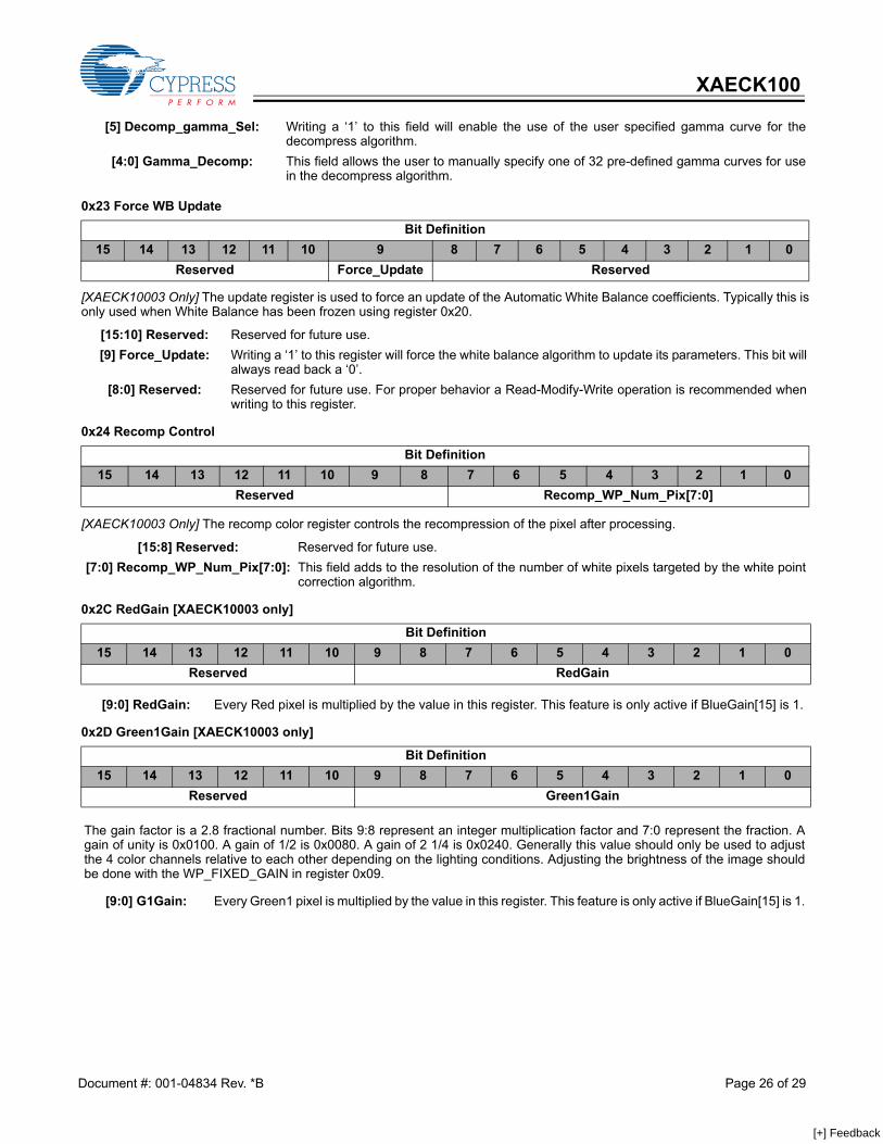
[5] Decomp_gamma_Sel: Writing a ‘1’ to this field will enable the use of the user specified gamma curve for thedecompress algorithm.
[4:0] Gamma_Decomp: This field allows the user to manually specify one of 32 pre-defined gamma curves for usein the decompress algorithm.
0x23 Force WB Update
Bit Definition15 14 13 12 11 10 9 8 7 6 5 4 3 2 1 0
Reserved Force_Update Reserved
[15:10] Reserved: Reserved for future use.[9] Force_Update: Writing a ‘1’ to this register will force the white balance algorithm to update its parameters. This bit will
always read back a ‘0’. [8:0] Reserved: Reserved for future use. For proper behavior a Read-Modify-Write operation is recommended when
writing to this register.
0x24 Recomp Control
Bit Definition15 14 13 12 11 10 9 8 7 6 5 4 3 2 1 0
Reserved Recomp_WP_Num_Pix[7:0]
[15:8] Reserved: Reserved for future use.[7:0] Recomp_WP_Num_Pix[7:0]: This field adds to the resolution of the number of white pixels targeted by the white point
correction algorithm.
0x2C RedGain [XAECK10003 only]
Bit Definition15 14 13 12 11 10 9 8 7 6 5 4 3 2 1 0
Reserved RedGain
[9:0] RedGain: Every Red pixel is multiplied by the value in this register. This feature is only active if BlueGain[15] is 1.
0x2D Green1Gain [XAECK10003 only]
Bit Definition15 14 13 12 11 10 9 8 7 6 5 4 3 2 1 0
Reserved Green1Gain
The gain factor is a 2.8 fractional number. Bits 9:8 represent an integer multiplication factor and 7:0 represent the fraction. Again of unity is 0x0100. A gain of 1/2 is 0x0080. A gain of 2 1/4 is 0x0240. Generally this value should only be used to adjustthe 4 color channels relative to each other depending on the lighting conditions. Adjusting the brightness of the image shouldbe done with the WP_FIXED_GAIN in register 0x09.
[9:0] G1Gain: Every Green1 pixel is multiplied by the value in this register. This feature is only active if BlueGain[15] is 1.
Document #: 001-04834 Rev. *B Page 26 of 29
[+] Feedback
XAECK100
Note: When Manual_WB is 0, registers 0x2C-0x2F will read the current automatic white balance value. When Manual_WB is 1, then the value written to each of theseregisters will be read back. When the automatic white balance is enabled, each of the 4 registers should be read and written back, and then Manual_WB set to 1.This will put the ECK into manual White Balance mode with no visible changes in the output video. The values in the gain registers can then be incrementally updatedto the desired White Balance levels.
0x30 Stereo Lock Status
The Stereo Lock Status register provides information about the status of the synchronization of the two cameras.
[XAECK10001 Only] The Manual Barrier Control Mode register is used to load or enable the manual user barrier control feature.The bits are defined as follows:
0x2E Green2Gain [XAECK10003 only]
Bit Definition15 14 13 12 11 10 9 8 7 6 5 4 3 2 1 0
Reserved Green2Gain
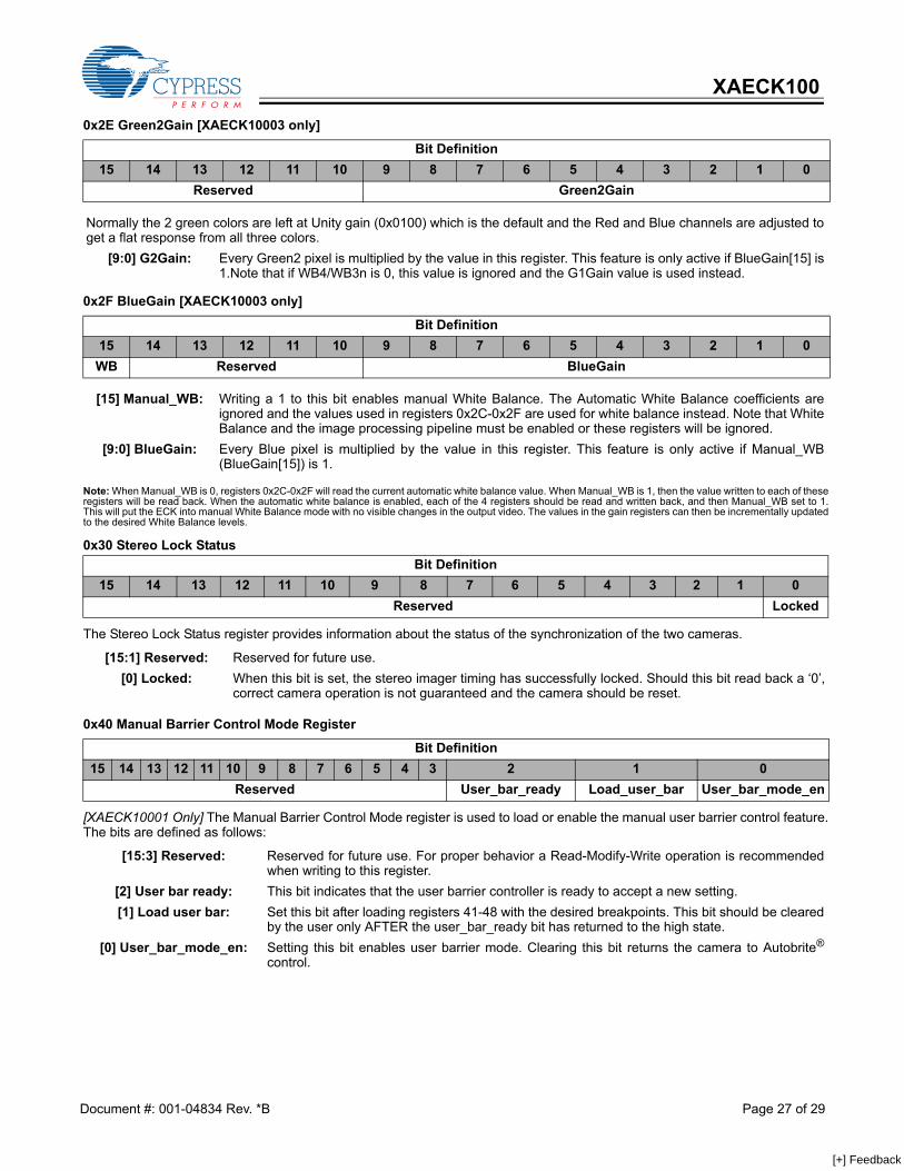
Normally the 2 green colors are left at Unity gain (0x0100) which is the default and the Red and Blue channels are adjusted toget a flat response from all three colors.
[9:0] G2Gain: Every Green2 pixel is multiplied by the value in this register. This feature is only active if BlueGain[15] is1.Note that if WB4/WB3n is 0, this value is ignored and the G1Gain value is used instead.
0x2F BlueGain [XAECK10003 only]
Bit Definition15 14 13 12 11 10 9 8 7 6 5 4 3 2 1 0WB Reserved BlueGain
[15] Manual_WB: Writing a 1 to this bit enables manual White Balance. The Automatic White Balance coefficients areignored and the values used in registers 0x2C-0x2F are used for white balance instead. Note that WhiteBalance and the image processing pipeline must be enabled or these registers will be ignored.
[9:0] BlueGain: Every Blue pixel is multiplied by the value in this register. This feature is only active if Manual_WB(BlueGain[15]) is 1.
Bit Definition15 14 13 12 11 10 9 8 7 6 5 4 3 2 1 0
Reserved Locked
[15:1] Reserved: Reserved for future use. [0] Locked: When this bit is set, the stereo imager timing has successfully locked. Should this bit read back a ‘0’,
correct camera operation is not guaranteed and the camera should be reset.
0x40 Manual Barrier Control Mode Register
Bit Definition15 14 13 12 11 10 9 8 7 6 5 4 3 2 1 0
Reserved User_bar_ready Load_user_bar User_bar_mode_en
[15:3] Reserved: Reserved for future use. For proper behavior a Read-Modify-Write operation is recommendedwhen writing to this register.
[2] User bar ready: This bit indicates that the user barrier controller is ready to accept a new setting. [1] Load user bar: Set this bit after loading registers 41-48 with the desired breakpoints. This bit should be cleared
by the user only AFTER the user_bar_ready bit has returned to the high state. [0] User_bar_mode_en: Setting this bit enables user barrier mode. Clearing this bit returns the camera to Autobrite®
control.
Document #: 001-04834 Rev. *B Page 27 of 29
[+] Feedback

XAECK100
[XAECK10001 Only] The Manual Barrier Breakpoint Control Breakpoint registers are used to set the row number at which thatspecific barrier is asserted.
Purchase of I2C serial interface components from Cypress or one of its sublicensed Associated Companies conveys a licenseunder the Philips I2C Patent Rights to use these components in a I2C system, provided that the system conforms to the I2CStandard Specification as defined by Philips.Windows is a registered trademark of Microsoft. Autobrite is a registered trademark of Cypress Semiconductor Corporation. Allproducts and company names mentioned in this document may be the trademarks of their respective holders.
0x41 to 0x48 Manual Barrier Control Breakpoint 1 to 8
Bit Definition15 14 13 12 11 10 9 8 7 6 5 4 3 2 1 0
BARRIER LEVEL ROWCOUNT
[15:12] BARRIER LEVEL: Set the barrier level that should be asserted in these four bits. Valid values are 0–7. A value of0 indicates the reset level, while a value of 7 indicates unhindered integration. Intermediatevalues can be used to hold the integration at a certain level.
[11:0] ROWCOUNT: This is a DOWN COUNTER that counts from the maximum number of rows down to 0. At row 0the data is read off the sensor so this point is fixed. The barrier level programmed above is asserted from the last change until the rowcountprogrammed here. From the next row on the next programmed barrier is used. See ECK 100 Barrier Voltage Control for details on usage and examples.
Document #: 001-04834 Rev. *B Page 28 of 29© Cypress Semiconductor Corporation, 2006. The information contained herein is subject to change without notice. Cypress Semiconductor Corporation assumes no responsibility for the useof any circuitry other than circuitry embodied in a Cypress product. Nor does it convey or imply any license under patent or other rights. Cypress products are not warranted nor intended to beused for medical, life support, life saving, critical control or safety applications, unless pursuant to an express written agreement with Cypress. Furthermore, Cypress does not authorize itsproducts for use as critical components in life-support systems where a malfunction or failure may reasonably be expected to result in significant injury to the user. The inclusion of Cypressproducts in life-support systems application implies that the manufacturer assumes all risk of such use and in doing so indemnifies Cypress against all charges.
[+] Feedback

XAECK100
Document #: 001-04834 Rev. *B Page 29 of 29
Document History Page
Document Title: XAECK100 Automotive Evaluation Kit Document Number: 001-04834
REV. ECN No. Issue DateOrig. of Change Description of Change
** 401656 See ECN SYT New Data Sheet*A 410276 See ECN SYT Replaced the Cross reference from “Figure 4” to “Figure 2” in the Color
Block Diagram section of Page 3.Changed “Star Killer” to “Defective Pixel Removal” in the block diagram of Fig 4.Added “Linear Re-map” explanations for Fig 4.Renamed “Imager Module Package” as “Camera Head” on Page 5.Corrected typo “1394” to “IEEE 1394” in the whole of the documentReversed the clock count in Fig 10 on Page 7.Changed “100 mil” to “.1 inch” in the Connector Definition on Page #7.Changed I2C to I2C in the whole of the documentCorrected typo “XAECK10001” to “XAECK10005” on Page # 8.Corrected typo in the DIP Switch Definitions column 3 from “XAECK10001” to “XAECK10005” on Page # 9.Added Barrel information for the 18° FOV Lens Specifications on Page # 13.
*B 436583 See ECN QGS In Features NTSC video changed to Analog NTSC video on page # 1.Added more explanation about I2C interface on page # 6.Added Mother Board Placement Diagram Of The ECK-100 Demo Kit diagram on page # 7.XAECK10003, Color Camera J15 on page # 8.Expanded the abbreviation for FOV as Field Of View on page # 13.Added more explanation for Register Description on page # 14.Register address 2C to 2F added in Register Description table on page # 15.Added Register explanations on page # 26.Note added in 0x0E Tint Status bit definition[11:0]CUR_TINT on page # 27.
[+] Feedback