Embed Size (px)
Citation preview

X95®
ASSAULT RIFLE / SUBMACHINE GUN
CALIBER: 5.56 MM / 9 MM PARABELLUM
TECHNICAL MANUAL
ISRAEL WEAPON INDUSTRIES (IWI) LTD.


TECHNICAL MANUAL FOR X95® ASSAULT RIFLE/SUBMACHINE GUN
P/N: 0070572002AEN REV.: 1.0

Copyright © 2010 by IWI-ISRAEL WEAPON INDUSTRIES (IWI) LTD.All rights reserved. This book, or parts thereof, may not be reproduced in any form without prior written permission from IWI-Israel Weapon Industries Ltd.In the interest of product improvement, its design and performance characteristics may be changed at any time without prior notice.English Edition Printing July 6, 2010ALL PATENTS PENDINGContact Information:Email: [email protected] Website: www.israel-weapon.com Postal Address: POB 63, Ramat HaSharon 47100, Israel
LIMITED PRODUCT WARRANTY1 This Warranty is given by ISRAEL WEAPON INDUSTRIES (IWI) LTD. ("IWI") solely to the original purchaser (the
"Purchaser") of IWI’s X95® ASSAULT RIFLE/SUBMACHINE GUN (the "Product") for a limited period of 12 months commencing from the date of Product shipment to the Purchaser (the "Warranty Period").
2 Subject to the limitations and exclusions contained below, IWI warrants the Product to be free from defects in design, materials and workmanship. Consequently, should any failure to conform to this Warranty be discovered and brought to the attention of IWI during the Warranty Period, and be substantiated by examination at IWI's facility or by duly autho-rized and certified field personnel on IWI's behalf, IWI, at its sole option and free of charge, shall either repair, replace or refund the purchase price of any non-conforming Product.
3 This Warranty shall only apply provided that:3.1 The Product has been transported and stored in its original package and stored, handled, maintained, operated and used
properly; all in accordance with IWI's updated instructions.
3.2 No changes, repairs or services were made to the Product by any party other than IWI or an authorized representative of IWI.
3.3 The Product was not damaged as a result of improper operation, misuse (whether intentional or otherwise), abuse, negli-gence, accident or flood, fire, earthquake or other external causes.
3.4 Only intact and appropriate standard ammunition, suitable for police and/or army use (as applicable to the Product), from a reputable manufacturer, was fired from the Product.
3.5 IWI shall have received a detailed written notification of the defect detected in the Product within 30 days from its detec-tion but no later than the end of the Warranty Period.
3.6 The defective Product and/or defected parts shall have been returned by the Purchaser to IWI immediately upon request in conformance with IWI's return procedures.
3.7 The Purchaser shall have obtained, at its own responsibility and cost, all licenses pertaining to the implementation of this Warranty (including import/export licenses and End-User certificate).
4 This Warranty does not apply to:4.1 Maintenance, repair or replacement of parts due to normal wear and tear.
4.2 Expendable items such as batteries (including battery leaks), bulbs, cleaning supplies and other consumables.
4.3 Any cosmetic damage that does not impede form, fit, and function of the Product.
4.4 Products with broken seals or that show evidence of tampering.
4.5 IWI does not warrant that the operation of the product will be uninterrupted or error-free.
5 In the event a Product returned to IWI is not defective in design, materials or workmanship or not returned within the Warranty Period, a test and evaluation charge, as determined by IWI, will apply.
6 IWI will be the sole determining evaluator and authority for adjudicating Warranty claims hereunder.7 THE REPAIR, REPLACEMENT, OR REFUND AS PROVIDED HEREINABOVE IS THE SOLE AND EXCLUSIVE
REMEDY OF THE PURCHASER, AND IS PROVIDED IN LIEU OF ALL OTHER WARRANTIES, EXPRESS OF IMPLIED, INCLUDING, WITHOUT LIMITATION, THE IMPLIED WARRANTIES OF MERCHANTABILITY, FIT-NESS FOR A PARTICULAR PURPOSE, NON-INFRINGEMENT, COURSE OF DEALING AND USAGE OF TRADE. IN NO EVENT SHALL IWI BE LIABLE TO PURCHASER, PURCHASER'S CUSTOMERS OR ANY THIRD PARTY, WHETHER IN CONTRACT OR TORT (INCLUDING NEGLIGENCE AND STRICT LIABILITY) FOR DAMAGES IN EXCESS OF THE PURCHASE PRICE OF THE PRODUCT, OR FOR ANY INDIRECT, INCIDENTAL, SPECIAL, PUNI-TIVE, OR CONSEQUENTIAL DAMAGES OR EXPENSES OF ANY KIND, OR PERSONAL INJURIES OR DAMAGE TO PROPERTY OF ANY KIND OR CHARACTER, OR LOSS OF REVENUE OR PROFITS, LOSS OF USE, LOSS OF BUSINESS, LOSS OF INFORMATION OR DATA OR OTHER FINANCIAL LOSS ARISING OUT OF OR IN CON-NECTION WITH THE ABILITY OR INABILITY TO USE THE PRODUCT TO THE FULL EXTENT THESE DAM-AGES MAY BE DISCLAIMED BY APPLICABLE LAW.
8 The provisions of this Warranty shall be governed by the laws of Israel and any legal proceedings relating thereto shall be held in the courts of the city of Tel-Aviv only.

WARNING
• All firearms are dangerous objects.
• When you pull the trigger, you must expect the weapon to fire, and you must assume full responsibility for this. Caution can prevent accidental discharge and avoid damage.
• Always assume that the weapon is loaded. To render it safe, set the safety lever to S, remove the maga-zine, and eject any remaining round by pulling the cocking handle to the rear; check the chamber to ver-ify the weapon is free of live cartridges.
• It is forbidden to alter or modify this firearm in any way. Any alterations or modifications of the firing mechanism may result in this firearm becoming unsafe, and will nullify all warranties.
CAUTION
Handling firearms safely is your own personal responsibility. Failure to comply the warnings in this manual may result in serious injury to you or others, as well as damage to the firearm or other property. Take note of the following warnings on firearm handling before attempting to use the weapon:
• Always check the chamber and magazine of the firearm before handling.
• Never load or carry a loaded firearm until you are ready to use it.
• Never point a firearm at anything you do not intend to shoot.
• Never place your finger on the trigger until you are ready to shoot.
• Never shoot unless you are absolutely sure of your target and what is beyond it.
• Know the range of your firearm.
• Always wear eye and ear protection when shooting.
• Never allow your firearm to be used by anyone who has not read this manual.
• Always be sure the barrel is clear of obstructions.
• Only carry ammunition specifically intended for the firearm you are using.
• Never use alcohol or drugs of any kind while using your firearm.
• Always store your unloaded firearm and ammunition separately, locked and inaccessible to children and unauthorized persons.

SAFETY REGULATION
• Firing the X95®will be done only by trained soldiers and according to the local user safety regulation.
• Firing the X95® in LEFT shooter configuration will be done only by left-handed shooters.
• Firing the X95® will be done with zeroed sights only.
• Service and maintenance of the X95® will be carried out with designated tools only.
HAZARD AWARENESS NOTICE
DO NOT SERVICE OR ADJUST ALONEUnder no circumstances will a person operate or maintain the X95® without the presence or assistance of another person capable of rendering aid.
Unless under direct supervision of a qualified person, no person shall operate or maintain the X95®, for which he is not qualified.
REPORT ALL HAZARDSIf at any time you detect a hazard, it is your responsibility to report the hazard to ensure that it is corrected.
If at any time you detect a “new” or “suspected new” hazard, particularly due to the weapon assembly, modification, or repair, it is your responsibility to ensure that a SAFETY notice is submitted to the Safety Center. This will ensure that the hazard be investigated, publicized, or corrected, as required.
AMMUNITION WARNING
• Use only original, high quality, commercially manufactured ammunition which is in good condition.
• Only use ammunition of the caliber for which your rifle is chambered. You will find the correct caliber engraved on the right side of the barrel.
• You should always use ammunition that complies with standards established by NATO.
• The use of hand-loaded, reloaded or other non- standard ammunition will void all warranties. The use of such ammunition can cause damage to the firearm and serious injury to the shooter or to others.
• It is not recommended to use ammunition not designed for firearms.

LIMITATION OF LIABILITYThis firearm is considered a dangerous weapon and is released by ISRAEL WEAPON INDUSTRIES (IWI) LTD. with the express understanding that ISRAEL WEAPON INDUSTRIES (IWI) LTD. shall not be responsible and shall not assume any liability whatsoever for any injury, death, or damage to property resulting from either intentional or accidental discharge of this firearm, or from its function when used for purposes or sub-jected to treatment for which it was not designed. ISRAEL WEAPON INDUSTRIES (IWI) LTD. will not be held liable for any injury, death or damage to any person or property resulting from any or a combination of the following: a) improper, careless or unsafe handling; b) use of the wrong caliber; c) use of ammunition other than the recommended high quality ammunition; d) unauthorized adjustments, repairs or alterations; e) corrosion or neglect; f ) other influences beyond ISRAEL WEAPON INDUSTRIES (IWI) LTD. direct and imme-diate control; g) use of this firearm for any purpose including civil defense, police activity, hunting danger-ous game, or combat. This statement of liability supersedes any other statement of liability, whether expressed or implied. The liability of ISRAEL WEAPON INDUSTRIES (IWI) LTD.. for any and all injuries and/or damages of any kind shall in no event exceed the purchase price of the firearm. In no event shall ISRAEL WEAPON INDUSTRIES (IWI) LTD. be liable for incidental or consequential damage.
ISRAEL WEAPON INDUSTRIES (IWI) LTD. reserves the right to make such alterations in design, dimensions, specifications and manufacture as are deemed necessary to ensure continuous improvement.


T
SSDF DSFADSAFSLD
SDFASDFSSIUHLKJHDF AASDF DF
ASDF SDF F
SDERSDFFWERSDASDF SDFF SFHJGF
ASDF
SDF SDF
Table of Contents
FOREWORD. . . . . . . . . . . . . . . . . . . . . . . . . . . . . . . . . . . . . . . . . . . . . . . . . . . . . . . . . . . . . . . . . . . . . . . . 1
CHAPTER 1: INTRODUCTION. . . . . . . . . . . . . . . . . . . . . . . . . . . . . . . . . . . . . . . . . . . . . . . . . 3
1.1. Technical Data . . . . . . . . . . . . . . . . . . . . . . . . . . . . . . . . . . . . . . . . . . . . . . . . . . . . . . . . . . . . . . . . . . 4
1.2. Features . . . . . . . . . . . . . . . . . . . . . . . . . . . . . . . . . . . . . . . . . . . . . . . . . . . . . . . . . . . . . . . . . . . . . . . . 8
CHAPTER 2: THEORY OF OPERATION . . . . . . . . . . . . . . . . . . . . . . . . . . . . . . . . . . . . 9
2.1. Main Parts . . . . . . . . . . . . . . . . . . . . . . . . . . . . . . . . . . . . . . . . . . . . . . . . . . . . . . . . . . . . . . . . . . . . . 10
2.2. Recoiling System. . . . . . . . . . . . . . . . . . . . . . . . . . . . . . . . . . . . . . . . . . . . . . . . . . . . . . . . . . . . . . . . 112.2.1. Moving Parts . . . . . . . . . . . . . . . . . . . . . . . . . . . . . . . . . . . . . . . . . . . . . . . . . . . . . . . . . . . . . . . . . . . 11
2.2.2. Operation Cycle . . . . . . . . . . . . . . . . . . . . . . . . . . . . . . . . . . . . . . . . . . . . . . . . . . . . . . . . . . . . . . . . 13
P/N: 0070572002AEN

technical manual for X95® Frontmatter
2.3. Trigger Mechanism . . . . . . . . . . . . . . . . . . . . . . . . . . . . . . . . . . . . . . . . . . . . . . . . . . . . . . . . . . . . . 162.3.1. Trigger Mechanism Parts . . . . . . . . . . . . . . . . . . . . . . . . . . . . . . . . . . . . . . . . . . . . . . . . . . . . . . . . . 16
2.3.2. Trigger Mechanism Operation . . . . . . . . . . . . . . . . . . . . . . . . . . . . . . . . . . . . . . . . . . . . . . . . . . . . 17
2.4. Mechanical Safeties . . . . . . . . . . . . . . . . . . . . . . . . . . . . . . . . . . . . . . . . . . . . . . . . . . . . . . . . . . . . . 20
CHAPTER 3: OPERATION. . . . . . . . . . . . . . . . . . . . . . . . . . . . . . . . . . . . . . . . . . . . . . . . . . . . . . 21
3.1. Safety Regulation . . . . . . . . . . . . . . . . . . . . . . . . . . . . . . . . . . . . . . . . . . . . . . . . . . . . . . . . . . . . . . . 22
3.2. Safety Inspection. . . . . . . . . . . . . . . . . . . . . . . . . . . . . . . . . . . . . . . . . . . . . . . . . . . . . . . . . . . . . . . . 23
3.3. Operating Instructions . . . . . . . . . . . . . . . . . . . . . . . . . . . . . . . . . . . . . . . . . . . . . . . . . . . . . . . . . . 24
3.4. Immediate Action. . . . . . . . . . . . . . . . . . . . . . . . . . . . . . . . . . . . . . . . . . . . . . . . . . . . . . . . . . . . . . . 25
CHAPTER 4: TROUBLESHOOTING . . . . . . . . . . . . . . . . . . . . . . . . . . . . . . . . . . . . . . . . . 27
CHAPTER 5: MAINTENANCE. . . . . . . . . . . . . . . . . . . . . . . . . . . . . . . . . . . . . . . . . . . . . . . . . 33
5.1. Repair & Maintenance Philosophy . . . . . . . . . . . . . . . . . . . . . . . . . . . . . . . . . . . . . . . . . . . . . . . . 34
5.2. Storage . . . . . . . . . . . . . . . . . . . . . . . . . . . . . . . . . . . . . . . . . . . . . . . . . . . . . . . . . . . . . . . . . . . . . . . . 355.2.1. General . . . . . . . . . . . . . . . . . . . . . . . . . . . . . . . . . . . . . . . . . . . . . . . . . . . . . . . . . . . . . . . . . . . . . . . 35
5.2.2. Guidelines for Storage. . . . . . . . . . . . . . . . . . . . . . . . . . . . . . . . . . . . . . . . . . . . . . . . . . . . . . . . . . . . 35
5.2.3. Armory Storage . . . . . . . . . . . . . . . . . . . . . . . . . . . . . . . . . . . . . . . . . . . . . . . . . . . . . . . . . . . . . . . . . 36
5.3. Weapon Service . . . . . . . . . . . . . . . . . . . . . . . . . . . . . . . . . . . . . . . . . . . . . . . . . . . . . . . . . . . . . . . . 385.3.1. Cleaning Tools . . . . . . . . . . . . . . . . . . . . . . . . . . . . . . . . . . . . . . . . . . . . . . . . . . . . . . . . . . . . . . . . . . 38
5.3.2. Maintenance Schedule . . . . . . . . . . . . . . . . . . . . . . . . . . . . . . . . . . . . . . . . . . . . . . . . . . . . . . . . . . . 39
5.3.3. General Servicing Procedure . . . . . . . . . . . . . . . . . . . . . . . . . . . . . . . . . . . . . . . . . . . . . . . . . . . . . . 41
5.3.4. Barrel Daily Service . . . . . . . . . . . . . . . . . . . . . . . . . . . . . . . . . . . . . . . . . . . . . . . . . . . . . . . . . . . . . 41
5.3.5. Bolt Carrier/Breech Block Group Daily Service. . . . . . . . . . . . . . . . . . . . . . . . . . . . . . . . . . . . . . . 42
5.3.6. Barrel Weekly Service . . . . . . . . . . . . . . . . . . . . . . . . . . . . . . . . . . . . . . . . . . . . . . . . . . . . . . . . . . . . 44
5.3.7. Internal Receiver Weekly Service. . . . . . . . . . . . . . . . . . . . . . . . . . . . . . . . . . . . . . . . . . . . . . . . . . . 45
5.3.8. Bolt Carrier Group Weekly Service in Assault Rifle Models. . . . . . . . . . . . . . . . . . . . . . . . . . . . . 46
5.3.9. Sear Mechanism Monthly Service . . . . . . . . . . . . . . . . . . . . . . . . . . . . . . . . . . . . . . . . . . . . . . . . . . 47
5.3.10. Safety Monthly Service . . . . . . . . . . . . . . . . . . . . . . . . . . . . . . . . . . . . . . . . . . . . . . . . . . . . . . . . . . . 48
ii Rev.: 1.0

Table of Contents
5.3.11. Magazine Monthly Service . . . . . . . . . . . . . . . . . . . . . . . . . . . . . . . . . . . . . . . . . . . . . . . . . . . . . . . 49
5.4. Weapon Inspection . . . . . . . . . . . . . . . . . . . . . . . . . . . . . . . . . . . . . . . . . . . . . . . . . . . . . . . . . . . . . 515.4.1. General Assembly Inspection . . . . . . . . . . . . . . . . . . . . . . . . . . . . . . . . . . . . . . . . . . . . . . . . . . . . . . 51
5.4.2. Visual Inspection. . . . . . . . . . . . . . . . . . . . . . . . . . . . . . . . . . . . . . . . . . . . . . . . . . . . . . . . . . . . . . . . 52
5.4.3. Functional Firing Test . . . . . . . . . . . . . . . . . . . . . . . . . . . . . . . . . . . . . . . . . . . . . . . . . . . . . . . . . . . 53
5.4.4. Accessories Inspection. . . . . . . . . . . . . . . . . . . . . . . . . . . . . . . . . . . . . . . . . . . . . . . . . . . . . . . . . . . . 54
5.5. Maintenance Under Extreme Conditions. . . . . . . . . . . . . . . . . . . . . . . . . . . . . . . . . . . . . . . . . . . 55
5.6. Maintenance Before and After Firing . . . . . . . . . . . . . . . . . . . . . . . . . . . . . . . . . . . . . . . . . . . . . . 57
CHAPTER 6: UNIT DISASSEMBLY . . . . . . . . . . . . . . . . . . . . . . . . . . . . . . . . . . . . . . . . . . 59
6.1. General Instructions for Weapon Disassembly . . . . . . . . . . . . . . . . . . . . . . . . . . . . . . . . . . . . . . 60
6.2. Unit Disassembly Procedures. . . . . . . . . . . . . . . . . . . . . . . . . . . . . . . . . . . . . . . . . . . . . . . . . . . . . 61
6.3. Installation/Removal of Optical Equipment . . . . . . . . . . . . . . . . . . . . . . . . . . . . . . . . . . . . . . . . 65
6.4. Installation/Removal of the Bayonet . . . . . . . . . . . . . . . . . . . . . . . . . . . . . . . . . . . . . . . . . . . . . . . 67
CHAPTER 7: FIELD DISASSEMBLY . . . . . . . . . . . . . . . . . . . . . . . . . . . . . . . . . . . . . . . . . 69
7.1. Tools and Materials for Weapon Service . . . . . . . . . . . . . . . . . . . . . . . . . . . . . . . . . . . . . . . . . . . 70
7.2. Field Disassembly Procedures . . . . . . . . . . . . . . . . . . . . . . . . . . . . . . . . . . . . . . . . . . . . . . . . . . . . 727.2.1. Flash Suppressor Disassembly at Echelon A. . . . . . . . . . . . . . . . . . . . . . . . . . . . . . . . . . . . . . . . . . 73
7.2.2. Integral Silencer Disassembly at Echelon A . . . . . . . . . . . . . . . . . . . . . . . . . . . . . . . . . . . . . . . . . . 75
7.2.3. Pistol Grip Disassembly at Echelon A. . . . . . . . . . . . . . . . . . . . . . . . . . . . . . . . . . . . . . . . . . . . . . . 77
7.2.4. Fore Grip Group Disassembly at Echelon A. . . . . . . . . . . . . . . . . . . . . . . . . . . . . . . . . . . . . . . . . . 79
7.2.5. Cocking Handle Bar Group Disassembly at Echelon A. . . . . . . . . . . . . . . . . . . . . . . . . . . . . . . . . 86
7.2.6. Barrel Group Disassembly at Echelon A. . . . . . . . . . . . . . . . . . . . . . . . . . . . . . . . . . . . . . . . . . . . . 89
7.2.7. Middle Swivel Disassembly at Echelon A . . . . . . . . . . . . . . . . . . . . . . . . . . . . . . . . . . . . . . . . . . . . 93
7.2.8. Trigger Disassembly at Echelon A. . . . . . . . . . . . . . . . . . . . . . . . . . . . . . . . . . . . . . . . . . . . . . . . . . 95
7.2.9. Butt Disassembly at Echelon A . . . . . . . . . . . . . . . . . . . . . . . . . . . . . . . . . . . . . . . . . . . . . . . . . . . . 98
7.2.10. Last Round Catch Group Disassembly at Echelon A . . . . . . . . . . . . . . . . . . . . . . . . . . . . . . . . . 100
7.2.11. Outer Receiver Group Disassembly at Echelon A . . . . . . . . . . . . . . . . . . . . . . . . . . . . . . . . . . . . 103
7.2.12. Magazine Adapter Disassembly at Echelon A . . . . . . . . . . . . . . . . . . . . . . . . . . . . . . . . . . . . . . . 110
7.2.13. Breech Block Group Disassembly in Submachine Gun Models at Echelon A . . . . . . . . . . . . . . 112
7.2.14. Bolt Carrier Group Disassembly in Assault Rifle Models at Echelons A & B . . . . . . . . . . . . . . 115
7.2.15. Gas Cylinder Disassembly at Echelons A & B . . . . . . . . . . . . . . . . . . . . . . . . . . . . . . . . . . . . . . . 123
P/N: 0070572002AEN iii

technical manual for X95® Frontmatter
7.2.16. Safety Group Disassembly at Echelon B . . . . . . . . . . . . . . . . . . . . . . . . . . . . . . . . . . . . . . . . . . . . 127
7.2.17. Sear Mechanism Disassembly at Echelon B . . . . . . . . . . . . . . . . . . . . . . . . . . . . . . . . . . . . . . . . . 131
CHAPTER 8: SPECIAL TOOLS & GAUGES. . . . . . . . . . . . . . . . . . . . . . . . . . . . . . .141
8.1. Nomenclature of SM&TEs . . . . . . . . . . . . . . . . . . . . . . . . . . . . . . . . . . . . . . . . . . . . . . . . . . . . . .142
8.2. Maintenance of SM&TEs . . . . . . . . . . . . . . . . . . . . . . . . . . . . . . . . . . . . . . . . . . . . . . . . . . . . . . . 144
8.3. Using SMTs. . . . . . . . . . . . . . . . . . . . . . . . . . . . . . . . . . . . . . . . . . . . . . . . . . . . . . . . . . . . . . . . . . . 1458.3.1. Using the Zeroing Wrench . . . . . . . . . . . . . . . . . . . . . . . . . . . . . . . . . . . . . . . . . . . . . . . . . . . . . . . 145
8.3.2. Using the Barrel Wrench . . . . . . . . . . . . . . . . . . . . . . . . . . . . . . . . . . . . . . . . . . . . . . . . . . . . . . . . 146
8.4. Using STEs—Gauge Inspection . . . . . . . . . . . . . . . . . . . . . . . . . . . . . . . . . . . . . . . . . . . . . . . . . .1478.4.1. Headspace Inspection . . . . . . . . . . . . . . . . . . . . . . . . . . . . . . . . . . . . . . . . . . . . . . . . . . . . . . . . . . . 148
8.4.2. Barrel Straightness Inspection . . . . . . . . . . . . . . . . . . . . . . . . . . . . . . . . . . . . . . . . . . . . . . . . . . . . 151
8.4.3. Barrel Wear Inspection. . . . . . . . . . . . . . . . . . . . . . . . . . . . . . . . . . . . . . . . . . . . . . . . . . . . . . . . . . 152
8.4.4. Firing Pin Protrusion Inspection in Assault Rifle Models. . . . . . . . . . . . . . . . . . . . . . . . . . . . . . 153
8.4.5. Silencer Centrality Inspection in Models with Integral Silencer . . . . . . . . . . . . . . . . . . . . . . . . . 154
CHAPTER 9: WEAPON CONVERSION. . . . . . . . . . . . . . . . . . . . . . . . . . . . . . . . . . . . 155
9.1. RH-LH Shooter Conversion . . . . . . . . . . . . . . . . . . . . . . . . . . . . . . . . . . . . . . . . . . . . . . . . . . . . .156
9.2. Caliber Conversion . . . . . . . . . . . . . . . . . . . . . . . . . . . . . . . . . . . . . . . . . . . . . . . . . . . . . . . . . . . .159
CHAPTER 10: AIMING SYSTEM . . . . . . . . . . . . . . . . . . . . . . . . . . . . . . . . . . . . . . . . . . . . . . 163
10.1. General. . . . . . . . . . . . . . . . . . . . . . . . . . . . . . . . . . . . . . . . . . . . . . . . . . . . . . . . . . . . . . . . . . . . . . . 164
10.2. Removal/Installation of the MEPRO 21 Integral Reflex Sight. . . . . . . . . . . . . . . . . . . . . . . . .165
10.3. Disassembling/Reassembling the Top Receiver Picatinny Adapter . . . . . . . . . . . . . . . . . . . . 167
10.4. Installation/Removal of the MEPRO 21 Detachable Reflex Sight. . . . . . . . . . . . . . . . . . . . . . 171
iv Rev.: 1.0

T
SSDF DSFADSAFSLD
SDFASDFSSIUHLKJHDF AASDF DF
ASDF SDF F
SDERSDFFWERSDASDF SDFF SFHJGF
ASDF
SDF SDF
List of Figures
Figure 1-1: X95® Models . . . . . . . . . . . . . . . . . . . . . . . . . . . . . . . . . . . . . . . . . . . . . . . . . . . . . . . . . . . 4Figure 2-1: Main Parts . . . . . . . . . . . . . . . . . . . . . . . . . . . . . . . . . . . . . . . . . . . . . . . . . . . . . . . . . . . 10Figure 2-2: Bolt Carrier Group . . . . . . . . . . . . . . . . . . . . . . . . . . . . . . . . . . . . . . . . . . . . . . . . . . . . 11Figure 2-3: Breech Block Group . . . . . . . . . . . . . . . . . . . . . . . . . . . . . . . . . . . . . . . . . . . . . . . . . . . . 12Figure 2-4: Operation Cycle . . . . . . . . . . . . . . . . . . . . . . . . . . . . . . . . . . . . . . . . . . . . . . . . . . . . . . . 13Figure 2-5: Trigger Mechanism Parts . . . . . . . . . . . . . . . . . . . . . . . . . . . . . . . . . . . . . . . . . . . . . . . 16Figure 2-6: Trigger . . . . . . . . . . . . . . . . . . . . . . . . . . . . . . . . . . . . . . . . . . . . . . . . . . . . . . . . . . . . . . 16Figure 2-7: Sear Mechanism . . . . . . . . . . . . . . . . . . . . . . . . . . . . . . . . . . . . . . . . . . . . . . . . . . . . . . 17Figure 2-8: Safe Mode. . . . . . . . . . . . . . . . . . . . . . . . . . . . . . . . . . . . . . . . . . . . . . . . . . . . . . . . . . . . 17Figure 2-9: Semi-Automatic Mode . . . . . . . . . . . . . . . . . . . . . . . . . . . . . . . . . . . . . . . . . . . . . . . . . 18Figure 2-10: Semi-Automatic Mode: First Round Fire . . . . . . . . . . . . . . . . . . . . . . . . . . . . . . . . . . 18Figure 2-11: Semi-Automatic Mode: Second & Subsequent Rounds Fire . . . . . . . . . . . . . . . . . . . 18Figure 2-12: Automatic Mode: First Round Fire . . . . . . . . . . . . . . . . . . . . . . . . . . . . . . . . . . . . . . . 19Figure 2-13: Automatic Mode: Sustained Fire . . . . . . . . . . . . . . . . . . . . . . . . . . . . . . . . . . . . . . . . . 19Figure 5-1: Cleaning Tools & Equipment . . . . . . . . . . . . . . . . . . . . . . . . . . . . . . . . . . . . . . . . . . . . 38Figure 5-2: Lubricating the Bolt Carrier Tracks. . . . . . . . . . . . . . . . . . . . . . . . . . . . . . . . . . . . . . . 42Figure 5-3: Lubricating the Breech Block Tracks . . . . . . . . . . . . . . . . . . . . . . . . . . . . . . . . . . . . . . 43Figure 5-4: Cleaning the Chamber & Barrel Extension . . . . . . . . . . . . . . . . . . . . . . . . . . . . . . . . 44Figure 5-5: Cleaning the Internal Receiver . . . . . . . . . . . . . . . . . . . . . . . . . . . . . . . . . . . . . . . . . . . 45
P/N: 0070572002AEN v

technical manual for X95® Frontmatter
Figure 5-6: Lubricating the Sear Mechanism Springs . . . . . . . . . . . . . . . . . . . . . . . . . . . . . . . . . . 47Figure 5-7: Disassembling the Magazine . . . . . . . . . . . . . . . . . . . . . . . . . . . . . . . . . . . . . . . . . . . . 49Figure 6-1: Secondary Disassembly. . . . . . . . . . . . . . . . . . . . . . . . . . . . . . . . . . . . . . . . . . . . . . . . . 62Figure 6-2: Removing the Sear Mechanism . . . . . . . . . . . . . . . . . . . . . . . . . . . . . . . . . . . . . . . . . . 64Figure 6-3: Gas Cylinder and Optical Accessories Adapter . . . . . . . . . . . . . . . . . . . . . . . . . . . . . 65Figure 6-4: Installing the Optical Device on the Gas Cylinder . . . . . . . . . . . . . . . . . . . . . . . . . . . 66Figure 6-5: Bayonet. . . . . . . . . . . . . . . . . . . . . . . . . . . . . . . . . . . . . . . . . . . . . . . . . . . . . . . . . . . . . . 67Figure 6-6: Installing the Bayonet . . . . . . . . . . . . . . . . . . . . . . . . . . . . . . . . . . . . . . . . . . . . . . . . . . 67Figure 7-1: Flash Suppressor Parts . . . . . . . . . . . . . . . . . . . . . . . . . . . . . . . . . . . . . . . . . . . . . . . . . 73Figure 7-2: Removing the Flash Suppressor . . . . . . . . . . . . . . . . . . . . . . . . . . . . . . . . . . . . . . . . . . 74Figure 7-3: Silencer . . . . . . . . . . . . . . . . . . . . . . . . . . . . . . . . . . . . . . . . . . . . . . . . . . . . . . . . . . . . . . 75Figure 7-4: Silencer Straightness Inspection . . . . . . . . . . . . . . . . . . . . . . . . . . . . . . . . . . . . . . . . . . 76Figure 7-5: Pistol Grip Parts . . . . . . . . . . . . . . . . . . . . . . . . . . . . . . . . . . . . . . . . . . . . . . . . . . . . . . 77Figure 7-6: Releasing the Pistol Grip Attachment Screw. . . . . . . . . . . . . . . . . . . . . . . . . . . . . . . . 78Figure 7-7: Releasing the Side Plate Attachment Screw . . . . . . . . . . . . . . . . . . . . . . . . . . . . . . . . 78Figure 7-8: Grip Group. . . . . . . . . . . . . . . . . . . . . . . . . . . . . . . . . . . . . . . . . . . . . . . . . . . . . . . . . . . 79Figure 7-9: Releasing the Fore Grip Adapter Screw . . . . . . . . . . . . . . . . . . . . . . . . . . . . . . . . . . . . 81Figure 7-10: Releasing the Assault Handle Locking Screw . . . . . . . . . . . . . . . . . . . . . . . . . . . . . . . 81Figure 7-11: Removing the Safety Pin. . . . . . . . . . . . . . . . . . . . . . . . . . . . . . . . . . . . . . . . . . . . . . . . 82Figure 7-12: Releasing the Windage Screw . . . . . . . . . . . . . . . . . . . . . . . . . . . . . . . . . . . . . . . . . . . . 82Figure 7-13: Disassembling the Front Sight Unit . . . . . . . . . . . . . . . . . . . . . . . . . . . . . . . . . . . . . . . 83Figure 7-14: Releasing the Picatinny Adapter Connecting Screw. . . . . . . . . . . . . . . . . . . . . . . . . . 83Figure 7-15: Installing the Front Sight Spring and the Leaf Spring . . . . . . . . . . . . . . . . . . . . . . . . 84Figure 7-16: Installing the Windage Screw Plunger Spring and the Windage Plunger . . . . . . . . 84Figure 7-17: Cocking Handle Bar Group . . . . . . . . . . . . . . . . . . . . . . . . . . . . . . . . . . . . . . . . . . . . . 86Figure 7-18: Extracting the Cocking Handle Bar from the Receiver . . . . . . . . . . . . . . . . . . . . . . . 87Figure 7-19: Detaching the Cocking Handle from the Cocking Handle Lever . . . . . . . . . . . . . . . 87Figure 7-20: Disassembling the Cocking Handle Bar . . . . . . . . . . . . . . . . . . . . . . . . . . . . . . . . . . . 88Figure 7-21: Barrel Group . . . . . . . . . . . . . . . . . . . . . . . . . . . . . . . . . . . . . . . . . . . . . . . . . . . . . . . . . 89Figure 7-22: Unlocking the Covering Plate of the Barrel Locking Pin . . . . . . . . . . . . . . . . . . . . . . 90Figure 7-23: Unlocking the Barrel . . . . . . . . . . . . . . . . . . . . . . . . . . . . . . . . . . . . . . . . . . . . . . . . . . . 90Figure 7-24: Separating the Front Shield from the Gas Cylinder . . . . . . . . . . . . . . . . . . . . . . . . . . 91Figure 7-25: Cocking Handle Bar Inside the Front Shield Hole . . . . . . . . . . . . . . . . . . . . . . . . . . . 91Figure 7-26: Barrel Locked . . . . . . . . . . . . . . . . . . . . . . . . . . . . . . . . . . . . . . . . . . . . . . . . . . . . . . . . . 92Figure 7-27: Middle Swivel Parts. . . . . . . . . . . . . . . . . . . . . . . . . . . . . . . . . . . . . . . . . . . . . . . . . . . . 93Figure 7-28: Removing the Swivel Lock Spring . . . . . . . . . . . . . . . . . . . . . . . . . . . . . . . . . . . . . . . . 93Figure 7-29: Unscrewing the Swivel . . . . . . . . . . . . . . . . . . . . . . . . . . . . . . . . . . . . . . . . . . . . . . . . . 94Figure 7-30: Aligning the Holes of the Middle Swivel and Its Lock . . . . . . . . . . . . . . . . . . . . . . . . 94
vi Rev.: 1.0

List of Figures
Figure 7-31: Trigger Unit . . . . . . . . . . . . . . . . . . . . . . . . . . . . . . . . . . . . . . . . . . . . . . . . . . . . . . . . . . 95Figure 7-32: Separating the Trigger Safety Device from the Trigger Bar. . . . . . . . . . . . . . . . . . . . 96Figure 7-33: Removing the Trigger Pivot . . . . . . . . . . . . . . . . . . . . . . . . . . . . . . . . . . . . . . . . . . . . . 96Figure 7-34: Trigger Spring Supported by the Projection on the Receiver . . . . . . . . . . . . . . . . . . . 97Figure 7-35: Butt Parts . . . . . . . . . . . . . . . . . . . . . . . . . . . . . . . . . . . . . . . . . . . . . . . . . . . . . . . . . . . . 98Figure 7-36: Releasing the Butt Pivot Screw . . . . . . . . . . . . . . . . . . . . . . . . . . . . . . . . . . . . . . . . . . . 99Figure 7-37: Last Round Catch Parts . . . . . . . . . . . . . . . . . . . . . . . . . . . . . . . . . . . . . . . . . . . . . . . 100Figure 7-38: Opening the Mechanism Locking Pins . . . . . . . . . . . . . . . . . . . . . . . . . . . . . . . . . . .101Figure 7-39: Removing the Last Round Catch . . . . . . . . . . . . . . . . . . . . . . . . . . . . . . . . . . . . . . . .101Figure 7-40: Disassembling the Last Round Catch Group . . . . . . . . . . . . . . . . . . . . . . . . . . . . . . 101Figure 7-41: Installing the Last Round Catch Spring Inside the Last Round Catch . . . . . . . . . . 102Figure 7-42: Positioning the Last Round Catch Unit Inside the Last Round Catch Lever . . . . .102Figure 7-43: Outer Receiver Group . . . . . . . . . . . . . . . . . . . . . . . . . . . . . . . . . . . . . . . . . . . . . . . . . 103Figure 7-44: Removing the Magazine Release Pivot Retaining Spring . . . . . . . . . . . . . . . . . . . .105Figure 7-45: Removing a Magazine Release Pivot . . . . . . . . . . . . . . . . . . . . . . . . . . . . . . . . . . . . .105Figure 7-46: Removing the Magazine Catch Pivot . . . . . . . . . . . . . . . . . . . . . . . . . . . . . . . . . . . . 106Figure 7-47: Releasing the Deflector Tightening Screw . . . . . . . . . . . . . . . . . . . . . . . . . . . . . . . . . 106Figure 7-48: Removing the Ejection Port Cover. . . . . . . . . . . . . . . . . . . . . . . . . . . . . . . . . . . . . . . 107Figure 7-49: Removing the Barrel Locking Pin . . . . . . . . . . . . . . . . . . . . . . . . . . . . . . . . . . . . . . .107Figure 7-50: Opening the Mechanism Locking Pin Spring . . . . . . . . . . . . . . . . . . . . . . . . . . . . . . 108Figure 7-51: Removing the Butt Locking Pin and Its Spring. . . . . . . . . . . . . . . . . . . . . . . . . . . . . 108Figure 7-52: Installing the Mechanism Locking Pin Spring . . . . . . . . . . . . . . . . . . . . . . . . . . . . .109Figure 7-53: Magazine Adapter Parts . . . . . . . . . . . . . . . . . . . . . . . . . . . . . . . . . . . . . . . . . . . . . . .110Figure 7-54: Disassembling the Magazine Adapter . . . . . . . . . . . . . . . . . . . . . . . . . . . . . . . . . . . . 111Figure 7-55: Installing the Magazine Adapter . . . . . . . . . . . . . . . . . . . . . . . . . . . . . . . . . . . . . . . . 111Figure 7-56: Breech Block Group . . . . . . . . . . . . . . . . . . . . . . . . . . . . . . . . . . . . . . . . . . . . . . . . . . . 112Figure 7-57: Removing the Extractor Back Pin . . . . . . . . . . . . . . . . . . . . . . . . . . . . . . . . . . . . . . .113Figure 7-58: Removing the Firing Pin . . . . . . . . . . . . . . . . . . . . . . . . . . . . . . . . . . . . . . . . . . . . . . .113Figure 7-59: Removing the Extractor Front Pin. . . . . . . . . . . . . . . . . . . . . . . . . . . . . . . . . . . . . . . 113Figure 7-60: Removing the Extractor . . . . . . . . . . . . . . . . . . . . . . . . . . . . . . . . . . . . . . . . . . . . . . . 114Figure 7-61: Bolt Carrier Group . . . . . . . . . . . . . . . . . . . . . . . . . . . . . . . . . . . . . . . . . . . . . . . . . . .115Figure 7-62: Removing the Bolt Carrier Back Pin . . . . . . . . . . . . . . . . . . . . . . . . . . . . . . . . . . . . .117Figure 7-63: Removing the General Pin . . . . . . . . . . . . . . . . . . . . . . . . . . . . . . . . . . . . . . . . . . . . .117Figure 7-64: Removing the Extractor from the Bolt . . . . . . . . . . . . . . . . . . . . . . . . . . . . . . . . . . .117Figure 7-65: Removing the Extractor Pivot . . . . . . . . . . . . . . . . . . . . . . . . . . . . . . . . . . . . . . . . . .118Figure 7-66: Removing the Piston Connector Pin . . . . . . . . . . . . . . . . . . . . . . . . . . . . . . . . . . . . . 119Figure 7-67: Disassembling the Ejector. . . . . . . . . . . . . . . . . . . . . . . . . . . . . . . . . . . . . . . . . . . . . .119Figure 7-68: Installing the Piston Connector Pin . . . . . . . . . . . . . . . . . . . . . . . . . . . . . . . . . . . . . . 120
P/N: 0070572002AEN vii
technical manual for X95® Frontmatter
Figure 7-69: Installing the Ejector Safety Pin Inside the Bolt . . . . . . . . . . . . . . . . . . . . . . . . . . . . 120Figure 7-70: Installing the Bolt Carrier Back Pin . . . . . . . . . . . . . . . . . . . . . . . . . . . . . . . . . . . . . 121Figure 7-71: Installing the General Pin . . . . . . . . . . . . . . . . . . . . . . . . . . . . . . . . . . . . . . . . . . . . . .121Figure 7-72: Gas Cylinder Parts . . . . . . . . . . . . . . . . . . . . . . . . . . . . . . . . . . . . . . . . . . . . . . . . . . .123Figure 7-73: Removing the Gas Cylinder . . . . . . . . . . . . . . . . . . . . . . . . . . . . . . . . . . . . . . . . . . . . 124Figure 7-74: Disassembling the Gas Cylinder . . . . . . . . . . . . . . . . . . . . . . . . . . . . . . . . . . . . . . . . 125Figure 7-75: Closing the Retaining Ring . . . . . . . . . . . . . . . . . . . . . . . . . . . . . . . . . . . . . . . . . . . . . 125Figure 7-76: Installing the Gas Cylinder . . . . . . . . . . . . . . . . . . . . . . . . . . . . . . . . . . . . . . . . . . . . . 126Figure 7-77: Safety Group . . . . . . . . . . . . . . . . . . . . . . . . . . . . . . . . . . . . . . . . . . . . . . . . . . . . . . . . 127Figure 7-78: Removing the Safety Plunger . . . . . . . . . . . . . . . . . . . . . . . . . . . . . . . . . . . . . . . . . . .128Figure 7-79: Removing the Safety . . . . . . . . . . . . . . . . . . . . . . . . . . . . . . . . . . . . . . . . . . . . . . . . . . 128Figure 7-80: Disassembling the Safety . . . . . . . . . . . . . . . . . . . . . . . . . . . . . . . . . . . . . . . . . . . . . . 129Figure 7-81: Installing the Safety Positioning Spring . . . . . . . . . . . . . . . . . . . . . . . . . . . . . . . . . . . 129Figure 7-82: Installing the Safety Inside the Receiver . . . . . . . . . . . . . . . . . . . . . . . . . . . . . . . . . . 130Figure 7-83: Sear Mechanism Parts . . . . . . . . . . . . . . . . . . . . . . . . . . . . . . . . . . . . . . . . . . . . . . . .131Figure 7-84: Releasing the Hammer from the Automatic Sear. . . . . . . . . . . . . . . . . . . . . . . . . . .133Figure 7-85: Releasing the Hammer from the Sear . . . . . . . . . . . . . . . . . . . . . . . . . . . . . . . . . . . . 133Figure 7-86: Removing the Hammer Securing Pin . . . . . . . . . . . . . . . . . . . . . . . . . . . . . . . . . . . . 134Figure 7-87: Removing the Hammer Pivot . . . . . . . . . . . . . . . . . . . . . . . . . . . . . . . . . . . . . . . . . . .134Figure 7-88: Releasing the Sear Activator Secondary Spring . . . . . . . . . . . . . . . . . . . . . . . . . . . . 134Figure 7-89: Removing the Sear Activator Unit from the Mechanism Housing . . . . . . . . . . . . . 135Figure 7-90: Disassembling the Sear Activator Unit—Step 1 . . . . . . . . . . . . . . . . . . . . . . . . . . . .135Figure 7-91: Disassembling the Sear Activator Unit—Step 2 . . . . . . . . . . . . . . . . . . . . . . . . . . . .135Figure 7-92: Disassembling the Sear Activator Unit—Step 3 . . . . . . . . . . . . . . . . . . . . . . . . . . . .136Figure 7-93: Disassembling the Sear Activator Unit—Step 4 . . . . . . . . . . . . . . . . . . . . . . . . . . . .136Figure 7-94: Hammer Spring Installed . . . . . . . . . . . . . . . . . . . . . . . . . . . . . . . . . . . . . . . . . . . . . .136Figure 7-95: Installing the Sear Plunger Spring . . . . . . . . . . . . . . . . . . . . . . . . . . . . . . . . . . . . . . .137Figure 7-96: Assembling the Sear Activator Unit. . . . . . . . . . . . . . . . . . . . . . . . . . . . . . . . . . . . . . 137Figure 7-97: Installing the Sear Pivot . . . . . . . . . . . . . . . . . . . . . . . . . . . . . . . . . . . . . . . . . . . . . . . 137Figure 7-98: Installing the Hammer . . . . . . . . . . . . . . . . . . . . . . . . . . . . . . . . . . . . . . . . . . . . . . . .138Figure 7-99: Installing the Hammer Pivot . . . . . . . . . . . . . . . . . . . . . . . . . . . . . . . . . . . . . . . . . . . 138Figure 7-100: Installing the Hammer Securing Pin . . . . . . . . . . . . . . . . . . . . . . . . . . . . . . . . . . . . .139Figure 8-1: Adjusting Elevation . . . . . . . . . . . . . . . . . . . . . . . . . . . . . . . . . . . . . . . . . . . . . . . . . . . 145Figure 8-2: Adjusting Windage . . . . . . . . . . . . . . . . . . . . . . . . . . . . . . . . . . . . . . . . . . . . . . . . . . .146Figure 8-3: Checking Headspace in Assault Rifle Models . . . . . . . . . . . . . . . . . . . . . . . . . . . . . . 148Figure 8-5: Inserting the Dummy Round into the Chamber . . . . . . . . . . . . . . . . . . . . . . . . . . . 149Figure 8-6: Installing the Adapter on the Dummy Round . . . . . . . . . . . . . . . . . . . . . . . . . . . . .149Figure 8-4: Headspace Gauge 9 mm . . . . . . . . . . . . . . . . . . . . . . . . . . . . . . . . . . . . . . . . . . . . . . .149
viii Rev.: 1.0

List of Figures
Figure 8-7: Checking Headspace in Submachine Gun Modelss . . . . . . . . . . . . . . . . . . . . . . . . . 150Figure 8-8: Barrel Straightness Inspection . . . . . . . . . . . . . . . . . . . . . . . . . . . . . . . . . . . . . . . . . .151Figure 8-9: Barrel Wear Inspection . . . . . . . . . . . . . . . . . . . . . . . . . . . . . . . . . . . . . . . . . . . . . . . . 152Figure 8-10: Firing Pin Protrusion Inspection . . . . . . . . . . . . . . . . . . . . . . . . . . . . . . . . . . . . . . . .153Figure 8-11: Silencer Centrality Inspection . . . . . . . . . . . . . . . . . . . . . . . . . . . . . . . . . . . . . . . . . .154Figure 9-1: Conversion to LH Shooter . . . . . . . . . . . . . . . . . . . . . . . . . . . . . . . . . . . . . . . . . . . . .156Figure 9-2: Converting the Front Shield for the LH Shooter. . . . . . . . . . . . . . . . . . . . . . . . . . . .157Figure 9-3: Conversion Kits for 9 mm and for 9 mm Silenced . . . . . . . . . . . . . . . . . . . . . . . . . . 159Figure 9-4: Conversion Kit for 5.56 mm . . . . . . . . . . . . . . . . . . . . . . . . . . . . . . . . . . . . . . . . . . . .160Figure 10-1: Integral MEPRO 21 Reflex Sight . . . . . . . . . . . . . . . . . . . . . . . . . . . . . . . . . . . . . . . . 165Figure 10-2: Removing the Integral MEPRO 21 Reflex Sight . . . . . . . . . . . . . . . . . . . . . . . . . . . .166Figure 10-3: Installing the MEPRO 21 Integral Reflex Sight . . . . . . . . . . . . . . . . . . . . . . . . . . . . 166Figure 10-4: Top Receiver Picatinny Adapter Parts . . . . . . . . . . . . . . . . . . . . . . . . . . . . . . . . . . . . 167Figure 10-5: Releasing the Rail Attachment Screws. . . . . . . . . . . . . . . . . . . . . . . . . . . . . . . . . . . . 168Figure 10-6: Releasing the Picatinny Adapter Base Attachment Screw . . . . . . . . . . . . . . . . . . . . 169Figure 10-7: Opening the Retaining Ring . . . . . . . . . . . . . . . . . . . . . . . . . . . . . . . . . . . . . . . . . . . .169Figure 10-8: Removing the Rear Sight . . . . . . . . . . . . . . . . . . . . . . . . . . . . . . . . . . . . . . . . . . . . . . 169Figure 10-9: Removing the Spiral Pin . . . . . . . . . . . . . . . . . . . . . . . . . . . . . . . . . . . . . . . . . . . . . . .170Figure 10-10: Detachable MEPRO 21 Reflex Sight . . . . . . . . . . . . . . . . . . . . . . . . . . . . . . . . . . . . . 171Figure 10-11: Detachable MEPRO 21 Reflex Sight: Quick-Release Adapter . . . . . . . . . . . . . . . .172
P/N: 0070572002AEN ix

technical manual for X95® Frontmatter
x Rev.: 1.0

FOREWORD
This manual is applicable to the following models:This manual explains in detail the maintenance and repair procedures for all models of the X95® family.
Read the manual carefully prior to carrying out any repairs on the weapon. Pay spe-cial attention to the safety warnings, cautions and notes.
X95 assault rifle, standard configuration
X95 CPRF assault rifle configuration with bayonet
X95 MSW semi-automatic configuration
X95 SMG submachine gun configuration
X95S SMG submachine gun configuration with integral silencer
P/N: 0070572002AEN 1

technical manual for X95®
DEFINITION OF WARNINGS, CAUTIONS, AND NOTES
Throughout this manual, special references are made when deemed important. Three classifications are used to separate these references by their order of impor-tance.
Warning Any procedure, practice, condition, etc., which may result in personal injury or loss of life if not strictly followed.
Caution Any procedure, practice, condition, etc., which may result in damage to equip-ment if not strictly followed.
Note Any procedure, practice, condition, etc., which should be emphasized.
2 Rev.: 1.0

CHAPTER 1
INTRODUCTIONThe X95®, manufactured by ISRAEL WEAPON INDUSTRIES (IWI) LTD., is a weapon system intended for use by the police and special units in every type of mod-ern warfare—anti-terror, urban warfare, adverse conditions, open terrain, etc.
The single platform accommodates two calibers, which results in two different weapons:
5.56x45 mm 9x19 mm
assault rife operating according to closed bolt principle with the bolt locking by rotation and unlocking by gas impact on piston head
submachine gun operating according to blowback principle, locking with breech block and return spring interia
P/N: 0070572002AEN 3

technical manual for X95® Chapter 1
1.1 Technical DataThe table below contains the technical data for the X95® models. For information on a specific model, refer to the respective column in the table.
Figure 1-1: X95® Models
X95 with flashlight and NVD X95 SMG with flashlight
X95 with flashlight and magnifier X95S SMG
4 Rev.: 1.0

Tabl
e 1.1:
X9
5® Fam
ily: T
echn
ical
Dat
aa
MO
DEL
X95
X95
CPRF
X95
MSW
X95
SMG
X95S
SM
G
GEN
ERA
L DES
CRIP
TIO
Nas
saul
t rifl
e 5.
56 m
m,
gas
oper
atio
n, b
ullp
up
conf
igur
atio
n
assa
ult r
ifle
5.56
mm
, ga
s op
erat
ion,
bul
lpup
co
nfig
urat
ion
assa
ult r
ifle
5.56
mm
, ga
s op
erat
ion,
bul
lpup
co
nfig
urat
ion
subm
achi
ne g
un 9
mm
, bl
owba
ck o
pera
tion,
bu
llpup
con
figur
atio
n
subm
achi
ne g
un 9
mm
, bl
owba
ck o
pera
tion,
bu
llpup
con
figur
atio
n
CALI
BER
5.56
x45
mm
5.56
x45
mm
5.56
x45
mm
9x19
mm
9x19
mm
AM
MU
NIT
ION
M85
5, S
S 10
9, o
r oth
er
amm
uniti
on o
f NAT
O
STD
M85
5, S
S 10
9, o
r oth
er
amm
uniti
on o
f NAT
O/
INSA
S (O
FB) S
TD
NAT
O S
TD9x
19 P
arab
ellu
m9x
19 P
arab
ellu
m
MA
GA
ZIN
E CA
PACI
TY25
/30
rds
30 rd
s25
/30
rds
32 rd
s32
rds
BORE
& C
HA
MBE
Rha
rd c
rom
edha
rd c
rom
edha
rd c
rom
edha
rd c
rom
edha
rd c
rom
ed
RECE
IVER
rein
cfor
ced
poly
mer
rein
cfor
ced
poly
mer
rein
cfor
ced
poly
mer
rein
cfor
ced
poly
mer
rein
cfor
ced
poly
mer
FIRE
SEL
ECTO
RS
(Saf
e)
A (A
uto)
R
(Sem
i-aut
o)
S (S
afe)
A
(Aut
o)
R (S
emi-a
uto)
S (S
afe)
A
(Aut
o)S
(Saf
e)
A (A
uto)
R
(Sem
i-aut
o)
S (S
afe)
A
(Aut
o)
R (S
emi-a
uto)
OPT
ICA
L DEV
ICES
inte
gral
refle
x si
ght
optio
n fo
r opt
ical
sig
ht
on P
icat
inny
ada
pter
varie
ty o
f opt
ical
acc
es-
sorie
s
inte
gral
refle
x si
ght
varie
ty o
f opt
ical
acc
es-
sorie
s
inte
gral
refle
x si
ght
optio
n fo
r opt
ical
sig
ht
on P
icat
inny
ada
pter
varie
ty o
f opt
ical
acc
es-
sorie
s
inte
gral
refle
x si
ght
optio
n fo
r opt
ical
sig
ht
on P
icat
inny
ada
pter
varie
ty o
f opt
ical
acc
es-
sorie
s
optic
al s
ight
on
Pica
-tin
ny a
dapt
er
varie
ty o
f opt
ical
acc
es-
sorie
s
P/N: 0070572002AEN 5

BACK
UP
SIG
HTS
fron
t sig
ht: p
ost-
type
w
ith tr
itium
rear
sig
ht: a
pper
ture
-ty
pe, w
ith o
ptio
n of
tri-
tium
fron
t sig
ht: p
ost-
type
w
ith tr
itium
rear
sig
ht: a
pper
ture
-ty
pe, w
ith o
ptio
n of
tri-
tium
fron
t sig
ht: p
ost-
type
w
ith tr
itium
rear
sig
ht: a
pper
ture
-ty
pe, w
ith o
ptio
n of
tri-
tium
fron
t sig
ht: p
ost-
type
w
ith tr
itium
rear
sig
ht: a
pper
ture
-ty
pe, w
ith o
ptio
n of
tri-
tium
fron
t sig
ht: p
ost-
type
w
ith tr
itium
rear
sig
ht: a
pper
ture
-ty
pe, w
ith o
ptio
n of
tri-
tium
BAYO
NET
OF
M8
TYPE
-+
--
-
SPEC
IAL T
OO
LS FO
R U
NIT
D
ISA
SSEM
BLY
--
--
-
CYC
LIC
RATE
OF
FIRE
700-
1000
rd/m
in70
0-10
00 rd
/min
700-
1000
rd/m
in75
0-12
00 rd
/min
750-
1200
rd/m
in
MU
ZZLE
VEL
OCI
TYB
860
m/s
ec86
0 m
/sec
tbd
m/s
ec40
0 m
/sec
280
m/s
ec
INTE
RCH
AN
GEA
BILI
TY O
F PA
RTS
BETW
EEN
MO
DEL
S
100%
100%
100%
100%
100%
LAST
RO
UN
D C
ATC
H+
++
++
PICA
TIN
NY
AD
APT
ERS
++
++
+
CEN
TER
OF
GRA
VITY
rear
rear
rear
rear
rear
AM
BID
EXTR
OU
S CO
N-
TRO
LS
++
++
+
CALI
BER
5.56
x45
mm
5.56
x45
mm
5.56
x45
mm
9x19
mm
9x19
mm
LEN
GTH
, OVE
RALL
590
mm
590
mm
590
mm
590
mm
655
mm
Tabl
e 1.1:
X9
5® Fam
ily: T
echn
ical
Dat
aa
MO
DEL
X95
X95
CPRF
X95
MSW
X95
SMG
X95S
SM
G
P/N: 0070572002AEN 6

LEN
GTH
, BA
RREL
330
mm
330
mm
330
mm
330
mm
275
mm
RIFL
ING
TW
IST
1:7”
1:7”
1:7”
1:10
”1:
10”
NET
WEI
GH
T (W
/O S
IGH
T, M
AG
AZI
NE)
3.17
kg
3.00
kg
3.02
kg
3.28
kg
2.70
kg
a.Te
chni
cal d
ata
is su
bjec
t to
chan
ge w
ithou
t prio
r not
ice.
b.Ap
prox
imat
e fig
ure,
depe
nds o
n am
mun
ition
type
.
Tabl
e 1.1:
X9
5® Fam
ily: T
echn
ical
Dat
aa
MO
DEL
X95
X95
CPRF
X95
MSW
X95
SMG
X95S
SM
G
P/N: 0070572002AEN 7

technical manual for X95® Chapter 1
1.2 FeaturesThe following are the features of all models of the X95®:
• bullpup configuration
• Model X95 MSW: semi-automatic mode only
• six holding points
• three-point swivel connection
• corrosion-resistant metal parts
• detachable barrel
• integral/detachable reflex sight
• Model X95 CRPF: bayonet
• Model X95S: integral silencer
• ambidextrous controls
• low maintenance
• interchangeable parts between different models
• folding backup sights with tritium source
• last round catch
• special patent to prevent injury caused by obstruction in chamber
• Picatinny adapters for optional equipment
• Models X95, X95 CRPF, X95 MSW: convertible to 9 mm
• Models X95 SMG, X95S SMG: convertible to 5.56 mm
8 Rev.: 1.0

CHAPTER 2
THEORY OF OPERATION
This chapter introduces the main parts and details the theory of operation of the X95®.
P/N: 0070572002AEN 9

technical manual for X95® Chapter 2
2.1 Main PartsThe following figure displays the parts of the X95®:
Figure 2-1: Main Parts
# PART DESCRIPTION # PART DESCRIPTION
1 flash suppressor 2 front swivel
3 front backup sight 4 Picatinny adapter
5 cocking handle 6 magazine release lever
7 fire selector 8 rear backup sight
9 barrel locking pin 10 gas cylinder
11 middle swivel 12 ejection port
13 sling attachment 14 butt
15 last round catch lever 16 magazine catch
17 magazine well 18 pistol grip
19 trigger 20 fore grip
12 4
3
5 6
8
9
10
12 13
1415
161719
18
20
7 11
10 Rev.: 1.0

Recoiling System
2.2 Recoiling SystemThe following paragraphs describe the recoiling system of the X95®.
2.2.1 Moving PartsThe moving parts of the X95® are as follows:
bolt carrier group in assault rifle models:
1 2
3
4
56
Figure 2-2: Bolt Carrier Group
# PART DESCRIPTION
1 piston
2 bolt carrier
3 return spring
4 buffer
5 bolt carrier guide
6 bolt
P/N: 0070572002AEN 11

technical manual for X95® Chapter 2
breech block group in submachine gun models:
Figure 2-3: Breech Block Group
1
32
# PART DESCRIPTION
1 breech block
2 return spring
3 buffer
12 Rev.: 1.0

Recoiling System
2.2.2 Operation CycleThe operation cycle consists of the following stages:
Figure 2-4: Operation Cycle
1. Loading
Loading is accomplished by inserting the magazine into the magazine well.
2. Cocking
• Manual cocking: when the cocking handle is pulled back, the bolt car-rier/breech block moves back catching the hammer by the sear.
• Automatic cocking:
3. Feeding
loading
cocking
feeding
locking
firingunlocking
extraction
ejection
1
2
3
4
56
7
8
assault rifle models:
When the projectile passes the gas port, part of the gas passes through the gas tube, hits the piston head, drives it back together with the bolt carrier and bolt.
submachine gun models:
When the projectile moves through the barrel, the breech block moves to the rear and cocking occurs automatically.
P/N: 0070572002AEN 13

technical manual for X95® Chapter 2
The recoil spring drives the recoiling system forward; the bolt/breech block hits the upper round in the magazine, driving it through the bullet ramp into the chamber.
5. Firing
Pulling the trigger causes the trigger bar movement that releases the ham-mer, which in turn strikes the firing pin.
The firing pin moves forward and strikes the primer.
6. Unlocking
7. Extraction
The extractor catches the bullet rim, and during the backward movement, the extractor pulls the spent case out of the chamber.
8. Ejection
4. Locking
assault rifle models:
Upon completion of the bolt travel forward, the bolt surface hits the round base and the bolt stops.The bolt carrier continues the forward travel causing rotational movement of the bolt, due to the locking helix on the bolt.The rotational movement locks the bolt locking lugs against the barrel extension lugs.
submachine gun models:
Upon completion of the its travel forward, the breech block surface hits the round base and the breech block stops.The breech block continues the forward travel and its mass interia seals the barrel.
assault rifle models
After the bullet is shot, part of the gas returns back through the gas port into the gas tube and hits the piston head. The piston starts to retreat the recoil-ing system.The bolt carrier moves back, while the bolt guide pin turns the bolt due to the bolt locking helix.The rotational movement causes unlocking and release of the bolt locking lugs from the barrel extension lugs.
submachine gun models
The accumulated gas pressure acts upon the cartridge in the chamber.The expanding gas retreats the recoiling system and simultaneously, accom-plishes a new cocking action.
14 Rev.: 1.0

Recoiling System
The spent case is supported in the chamber and the barrel extension at the beginning of the return system backward movement. The spring-loaded ejector applies force on the rim until the spent case loses the barrel exten-sion support and the spent case is ejected through the ejection port by the compressed ejector spring force.
CYCLE COMPLETE.
P/N: 0070572002AEN 15

technical manual for X95® Chapter 2
2.3 Trigger MechanismThe following paragraphs describe the trigger mechanism of the X95®.
2.3.1 Trigger Mechanism PartsThe following figure displays the trigger mechanism of the X95®.
Figure 2-5: Trigger Mechanism Parts
Trigger The following figure displays the trigger of the X95®:
Figure 2-6: Trigger
# PART DESCRIPTION
1 trigger
2 trigger bar
3 sear mechanism
1
2
3
16 Rev.: 1.0

Trigger Mechanism
Sear mechanism
The following figures displays the sear mechanism of the X95®.
Figure 2-7: Sear Mechanism
2.3.2 Trigger Mechanism OperationThe following paragraphs describe how the trigger sear mechanism of the X95® operates.
Safe mode The safe mode is as follows:
The fire selector is located behind the trigger bar and prevents the trigger move-ment.
Figure 2-8: Safe Mode
# PART DESCRIPTION
1 hammer
2 sear activator
3 sear
4 automatic sear
1
2
3
4
P/N: 0070572002AEN 17

technical manual for X95® Chapter 2
Semi-automatic mode
The semi-automatic fire mode is as follows:
Each time the trigger is pulled, a single round is fired.
Figure 2-9: Semi-Automatic Mode
First round fire. Setting fire selector to semi-automatic mode enables pull-ing the trigger.
Pulling the trigger pulls the trigger bar which pulls the sear activator.
The turn of the sear activator allows the sear to release the hammer.
The released hammer hits the firing pin and causes the firing of a round.
Figure 2-10: Semi-Automatic Mode: First Round Fire
Second & subsequent rounds fire. After the first round is fired (while the shooter still pulls the trigger), the moving parts travel backward.
While the moving parts are in the recoiled position, the hammer is caught on the automatic sear. Only after the bolt carrier/ breech block moves forward and retracts, will it press the automatic sear and release the hammer to the sear.
Upon trigger release, the sear activator is seated under the sear tail, ready to push it when the trigger is pulled again.
Another pull of the trigger starts the cycle from the beginning.
Figure 2-11: Semi-Automatic Mode: Second & Subsequent Rounds Fire
18 Rev.: 1.0

Trigger Mechanism
Automatic mode (automatic models only)
The automatic mode is as follows:
First round fire. Setting fire selector to automatic mode enables longer trig-ger movement so that the sear activator accomplishes a longer rotational move-ment, neutralizing the sear from the hammer.
The released hammer hits the firing pin.
Figure 2-12: Automatic Mode: First Round Fire
Sustained fire. After the first round fire, firing is automatic (as long as the shooter is pulling the trigger).
When the moving parts travel back, the hammer is forced down.
Longer trigger pulling causes the sear activator to accomplish longer rotational movement, neutralizing the sear from the hammer.
The hammer is caught by the automatic sear.
The forward travel of the bolt carrier/breech block causes its rear section to hit the automatic sear, releasing the hammer.
The hammer, which is released of the automatic sear, accomplishes another fir-ing operation. This goes on similarly as long as the trigger is pulled.
When the shooter releases the trigger, the sear catches the hammer and cuts the cycle.
Figure 2-13: Automatic Mode: Sustained Fire
P/N: 0070572002AEN 19

technical manual for X95® Chapter 2
2.4 Mechanical SafetiesThe X95® is equipped with mechanical safeties that prevent accidental discharge.
First mechanical safety (assault rifle models)
The first mechanical safety prevents firing before locking is complete.
• The firing pin does not protrude over the bolt surface unless the bolt has completed its forward travel and is locked in the barrel extension.
• The bolt is completely locked in the barrel extension 0.078" (2 mm) before the bolt carrier completes its forward travel. In case the hammer is acci-dentally released before the bolt carrier movement completion, it hits the bolt carrier body rather than the firing pin.
Second mechanical safety (assault rifle models)
Prevents unlocking of the bolt until the pressure in the barrel drops to safe level:
• the time needed for the gas to expand in the gas passage
• unlocking is possible only by the piston
• the neutral stroke of the bolt carrier
Third mechanical safety
If the weapon is dropped accidentally, the trigger safety device locks the sear mechanism in the safe position and blocks the release of the hammer.
20 Rev.: 1.0

CHAPTER 3
OPERATIONThis chapter contains the safety regulation for using the weapon, instructions for safety inspection, feeding, loading, firing, and unloading of the weapon.
P/N: 0070572002AEN 21

technical manual for X95® Chapter 3
3.1 Safety RegulationStrictly observe the following safety regulation while using the weapon:
• Firing the weapon will be done only by trained soldiers and according to the local user safety regulations.
• Only left-handed soldiers may fire the weapon in LH configuration.
• The weapon will always be checked upon reception or handing over.
• Firing the weapon will be done with zeroed sights only.
• Maintenance will be carried out with proper tools only.
AMMUNITIONWARNING
• Use only original, high quality commercial manufactured ammunition that is in good condition. Use only ammunition of the caliber your weapon is cham-bered for. You can find the correct caliber engraved on the side of the barrel. Never use ammunition of any other caliber.
• Always use ammunition that complies with the performance standards estab-lished by NATO. The use of hand-loaded, reloaded or other non-standard ammunition voids all warranties.
• Never try to fire a cartridge that is heavily corroded, dented, or one that has a loose bullet.
• Never try to clean a cartridge with gasoline (petrol) or any other inflammable material, detergents, or solvents.
22 Rev.: 1.0

Safety Inspection
3.2 Safety InspectionPerform the safety inspection as follows:
1. Verify the weapon is safe without magazine.
2. Raise the weapon to a 60° angle, with clear view.
3. Check the safety.
4. Cock two times and hold the cocking handle back.
5. Lower the weapon to a 45° angle downwards; observe the chamber.
6. Release the cocking handle.
7. Open the safety.
8. Raise the weapon to 60° and pull the trigger.
9. Safe the weapon.
Task Completed.
P/N: 0070572002AEN 23

technical manual for X95® Chapter 3
3.3 Operating InstructionsOperate the weapon as follows:
1. LOAD
a. Fill the magazine with rounds.
b. Insert the magazine into the weapon magazine housing until a click of the magazine catch is heard.
c. Verify that pulling it down cannot draw out the magazine.
2. FEED
a. Raise the weapon 60° up.
b. Hold the pistol grip with all five fingers.
c. Confirm safe.
d. Cock the weapon by pulling the cocking handle back and releasing it.
e. Move to firing position.
3. FIRE
a. Aim the weapon at the target and position the safety lever to R.
b. Pull the trigger.
When the bullets in the magazine run out (stoppage 3), do the following:
i. Remove the empty magazine and insert a full magazine.
ii. Press the last round catch to release the recoiling system and load a new round.
If the weapon fails to fire, perform the immediate action. (Refer to the Immediate Action procedure on page 25.)
4. UNLOAD
a. Confirm safe.
b. Move to standing position, weapon at 60° up.
c. Hold the pistol grip with all five fingers.
d. Confirm safe.
e. Remove the magazine.
24 Rev.: 1.0

Operating Instructions
f. Discharge the weapon as follows:
g. Weapon at 60° up, cock two times and hold the cocking handle back.
h. Weapon at 45° downwards, verify the barrel chamber is clear.
i. Weapon at 60° up, open the safety and pull the trigger.
j. Confirm safe.
k. Announce “Weapon discharged, checked, and safe”.
Task Completed.
3.4 Immediate ActionIf the weapon fails to fire, immediate action must be taken before investigating the cause of the fault.
Immediate action involves the following operation:
1. TAP
Tap the magazine base upwards to make sure the magazine is properly seated.
WARNING! Before proceeding to investigate the cause of any fault, verify that:
• The weapon is properly assembled.
• The weapon is properly cleaned and lubricated, the barrel, chamber, andbolt carrier/breech block head are completely dried.
• The ammunition batch has been inspected and approved for use.
• The magazine is intact and not loaded with more than the designated num-ber of rounds.
P/N: 0070572002AEN 25

technical manual for X95® Chapter 3
2. COCK
Pull the cocking handle all the way back. Watch the ejection of the car-tridge or cartridge case.
3. RELEASE
If the cartridge or cartridge case is ejected, release the cocking handle to feed a new round.
4. AIM AND FIRE
Aim and pull the trigger.If, after repeating the above operation twice, the weapon still fails to fire, proceed as follows:
A. LOWER
Lower the weapon, move the safety to Safe, and remove the magazine.
B. COCK
Pull the cocking handle all the way to the rear.
C. LOOK
Look inside the ejection port.
D. LOCATE
Locate the fault by inspecting the chamber and bolt carrier/breech block face.
E. FIX
Fix the fault and continue firing. (See Troubleshooting Chart on page 28.)
Task Completed.
26 Rev.: 1.0

CHAPTER 4
TROUBLE-SHOOTING
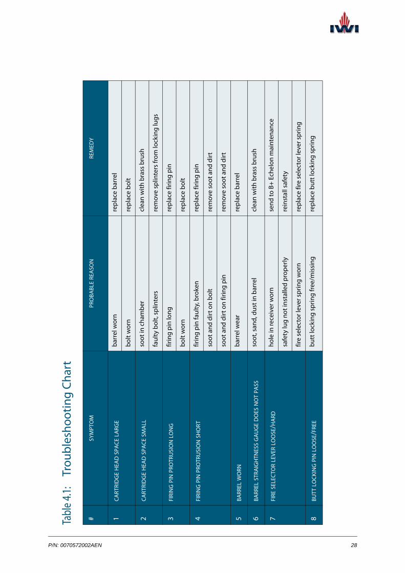
This chapter contains the troubleshooting information for the X95®. For each symp-tom, the probable reason is provided, as well as the instructions for remedy action.
P/N: 0070572002AEN 27
Ta
ble 4
.1:
Trou
bles
hoot
ing
Char
t
#SY
MPT
OM
PRO
BABL
E REA
SON
REM
EDY
1CA
RTRI
DG
E H
EAD
SPA
CE LA
RGE
barr
el w
orn
repl
ace
barr
el
bolt
wor
n re
plac
e bo
lt
2CA
RTRI
DG
E H
EAD
SPA
CE S
MA
LLso
ot in
cha
mbe
rcl
ean
with
bra
ss b
rush
faul
ty b
olt,
splin
ters
rem
ove
splin
ters
from
lock
ing
lugs
3FI
RIN
G P
IN P
ROTR
USI
ON
LON
Gfir
ing
pin
long
repl
ace
firin
g pi
n
bolt
wor
n re
plac
e bo
lt
4FI
RIN
G P
IN P
ROTR
USI
ON
SH
ORT
firin
g pi
n fa
ulty
, bro
ken
repl
ace
firin
g pi
n
soot
and
dirt
on
bolt
rem
ove
soot
and
dirt
soot
and
dirt
on
firin
g pi
nre
mov
e so
ot a
nd d
irt
5BA
RREL
WO
RNba
rrel
wea
rre
plac
e ba
rrel
6BA
RREL
STR
AIG
HTN
ESS
GA
UG
E D
OES
NO
T PA
SSso
ot, s
and,
dus
t in
barr
elcl
ean
with
bra
ss b
rush
7FI
RE S
ELEC
TOR
LEVE
R LO
OSE
/HA
RDho
le in
rece
iver
wor
nse
nd to
B+
Ech
elon
mai
nten
ance
safe
ty lu
g no
t ins
talle
d pr
oper
lyre
inst
all s
afet
y
fire
sele
ctor
leve
r spr
ing
wor
nre
plac
e fir
e se
lect
or le
ver s
prin
g
8BU
TT LO
CKIN
G P
IN LO
OSE
/FRE
Ebu
tt lo
ckin
g sp
ring
free
/mis
sing
repl
ace
butt
lock
ing
sprin
g
P/N: 0070572002AEN 28
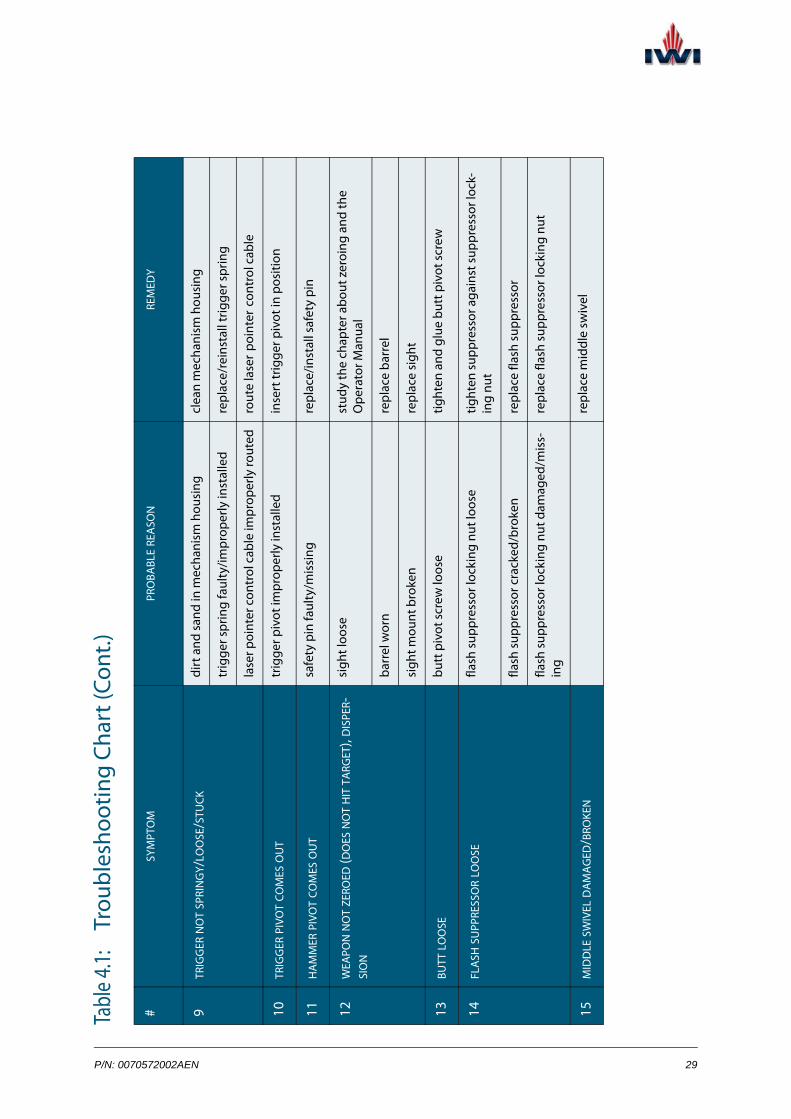
9TR
IGG
ER N
OT
SPRI
NG
Y/LO
OSE
/STU
CKdi
rt a
nd s
and
in m
echa
nism
hou
sing
clea
n m
echa
nism
hou
sing
trig
ger s
prin
g fa
ulty
/impr
oper
ly in
stal
led
repl
ace/
rein
stal
l trig
ger s
prin
g
lase
r poi
nter
con
trol
cab
le im
prop
erly
rout
edro
ute
lase
r poi
nter
cont
rol c
able
10TR
IGG
ER P
IVO
T CO
MES
OU
Ttr
igge
r piv
ot im
prop
erly
inst
alle
din
sert
trig
ger p
ivot
in p
ositi
on
11H
AM
MER
PIV
OT
COM
ES O
UT
safe
ty p
in fa
ulty
/mis
sing
repl
ace/
inst
all s
afet
y pi
n
12W
EAPO
N N
OT
ZERO
ED (D
OES
NO
T H
IT T
ARG
ET),
DIS
PER-
SIO
N
sigh
t loo
sest
udy
the
chap
ter a
bout
zer
oing
and
the
Ope
rato
r Man
ual
barr
el w
orn
repl
ace
barr
el
sigh
t mou
nt b
roke
nre
plac
e si
ght
13BU
TT LO
OSE
butt
piv
ot s
crew
loos
etig
hten
and
glu
e bu
tt p
ivot
scr
ew
14FL
ASH
SU
PPRE
SSO
R LO
OSE
flash
sup
pres
sor l
ocki
ng n
ut lo
ose
tight
en s
uppr
esso
r aga
inst
sup
pres
sor l
ock-
ing
nut
flash
sup
pres
sor c
rack
ed/b
roke
nre
plac
e fla
sh s
uppr
esso
r
flash
sup
pres
sor l
ocki
ng n
ut d
amag
ed/m
iss-
ing
repl
ace
flash
sup
pres
sor l
ocki
ng n
ut
15M
IDD
LE S
WIV
EL D
AM
AG
ED/B
ROKE
Nre
plac
e m
iddl
e sw
ivel
Tabl
e 4.1:
Tr
oubl
esho
otin
g Ch
art (
Cont
.)
#SY
MPT
OM
PRO
BABL
E REA
SON
REM
EDY
P/N: 0070572002AEN 29

16FA
ILU
RE T
O LO
CKdi
rt, s
and,
soo
t in
cham
ber a
nd b
arre
l ext
en-
sion
clea
n w
ith b
rass
bru
sh
soot
in c
ham
ber
clea
n w
ith b
rass
bru
sh
gas
cylin
der d
isto
rted
/dam
aged
/dirt
y (s
oot)
repl
ace
gas
cylin
der
cart
ridge
stu
ck in
cha
mbe
rre
mov
e w
ith e
vacu
atio
n pl
ug
retu
rn s
prin
g w
eak/
dam
aged
/dis
tort
edre
plac
e re
turn
spr
ing
amm
uniti
on fa
ulty
/dis
tort
edre
plac
e am
mun
ition
cock
ing
hand
le b
ar d
isto
rted
repl
ace
cock
ing
hand
le b
ar
cock
ing
hand
le g
uide
dam
aged
/dis
tort
edre
plac
e co
ckin
g ha
ndle
gui
de
17FA
ILU
RE T
O LO
AD
mag
azin
e da
mag
ed/c
rack
edre
plac
e m
agaz
ine
mag
azin
e ca
tch
step
faul
ty/b
roke
nre
plac
e m
agaz
ine
catc
h
18FA
ILU
RE T
O FE
EDm
agaz
ine
lips
dam
aged
/pre
ssed
repl
ace
mag
azin
e
mag
azin
e da
mag
ed/p
ress
edre
plac
e m
agaz
ine
mag
azin
e sp
ring
wea
k/di
stor
ted
repl
ace
mag
azin
e sp
ring
gas
cylin
der d
irty
(soo
t)cl
ean/
repl
ace
gas
cylin
der
bolt
faul
ty/w
orn
repl
ace
bolt
Tabl
e 4.1:
Tr
oubl
esho
otin
g Ch
art (
Cont
.)
#SY
MPT
OM
PRO
BABL
E REA
SON
REM
EDY
P/N: 0070572002AEN 30
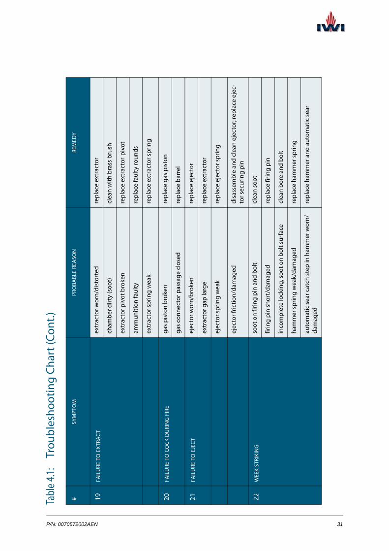
19FA
ILU
RE T
O EX
TRA
CT
extr
acto
r wor
n/di
stor
ted
repl
ace
extr
acto
r
cham
ber d
irty
(soo
t)cl
ean
with
bra
ss b
rush
extr
acto
r piv
ot b
roke
nre
plac
e ex
trac
tor p
ivot
amm
uniti
on fa
ulty
repl
ace
faul
ty ro
unds
extr
acto
r spr
ing
wea
kre
plac
e ex
trac
tor s
prin
g
20FA
ILU
RE T
O C
OCK
DU
RIN
G F
IRE
gas
pist
on b
roke
nre
plac
e ga
s pi
ston
gas
conn
ecto
r pas
sage
clo
sed
repl
ace
barr
el
21FA
ILU
RE T
O E
JECT
ejec
tor w
orn/
brok
enre
plac
e ej
ecto
r
extr
acto
r gap
larg
ere
plac
e ex
trac
tor
ejec
tor s
prin
g w
eak
repl
ace
ejec
tor s
prin
g
ejec
tor f
rictio
n/da
mag
eddi
sass
embl
e an
d cl
ean
ejec
tor;
repl
ace
ejec
-to
r sec
urin
g pi
n
22W
EEK
STRI
KIN
Gso
ot o
n fir
ing
pin
and
bolt
clea
n so
ot
firin
g pi
n sh
ort/
dam
aged
repl
ace
firin
g pi
n
inco
mpl
ete
lock
ing,
soo
t on
bolt
surf
ace
clea
n bo
re a
nd b
olt
ham
mer
spr
ing
wea
k/da
mag
edre
plac
e ha
mm
er s
prin
g
auto
mat
ic s
ear c
atch
ste
p in
ham
mer
wor
n/da
mag
edre
plac
e ha
mm
er a
nd a
utom
atic
sea
r
Tabl
e 4.1:
Tr
oubl
esho
otin
g Ch
art (
Cont
.)
#SY
MPT
OM
PRO
BABL
E REA
SON
REM
EDY
P/N: 0070572002AEN 31

23FA
ULT
Y CA
RTRI
DG
E, EX
TRA
CTO
R CA
TCH
ING
IN B
ULL
ET
RIM
dirt
/soo
t in
cham
ber
clea
n w
ith b
rass
bru
sh
cham
ber d
amag
ed/e
rode
dre
plac
e ba
rrel
extr
acto
r gap
larg
ere
plac
e ex
trac
tor/
bolt
wea
pon
expl
oded
/blo
cked
send
to a
ppro
pria
te m
aint
enan
ce e
chel
on
24CA
RTRI
DG
E H
AVI
NG
PRE
SSIN
G S
IGN
S—LO
NG
WIS
E A
ND
W
IDTH
WIS
E
soot
/san
d in
cha
mbe
rcl
ean
with
bra
ss b
rush
cham
ber d
amag
ed/e
rode
dre
plac
e ba
rrel
25D
ISCO
NN
ECTO
R FA
ILS
TO F
UN
CTI
ON
—U
NIN
TEN
TIO
NA
L FI
RE IN
AU
TOM
ATI
C M
OD
E
ham
mer
wor
nre
plac
e ha
mm
er
disc
onne
ctor
wor
nre
plac
e di
scon
nect
or
26H
ARD
CO
CKIN
Gba
rrel
lock
ing
pin
turn
ed in
com
plet
ely
com
plet
e ba
rrel
lock
ing
pin
turn
reco
iling
sys
tem
dirt
y/dr
ycl
ean
and
lubr
icat
e re
coili
ng s
yste
m a
dn
body
inte
rior
cock
ing
hand
le g
uide
mis
loca
ted
rein
stal
l coc
king
han
dle
guid
e
cock
ing
hand
le b
ar d
isto
rted
repl
ace
cock
ing
hand
le b
ar
Tabl
e 4.1:
Tr
oubl
esho
otin
g Ch
art (
Cont
.)
#SY
MPT
OM
PRO
BABL
E REA
SON
REM
EDY
P/N: 0070572002AEN 32

CHAPTER 5
MAINTENANCEStrict adherence to the maintenance schedule and procedures ensures the weapon combat readiness and proper operation at all times.
This chapter discusses the storage, periodic maintenance, maintenance before and after firing, and maintenance in extreme conditions, for the X95®.
P/N: 0070572002AEN 33

technical manual for X95® Chapter 5
5.1 Repair & Maintenance Philosophy
The following paragraphs explain the various maintenance echelons for the X95®.
Unit repairs cleaning, lubrication, minor repairs and replacements of components and minor assemblies within the unit holding the weapons with tools generally held within the unit
See “Cleaning Tools & Equipment” on page 38.
Field repairs repairs and replacements of major assemblies and other components beyond the scope of unit level repairs, carried out in the field by specially trained ordnance personnel:
Echelon A:
See “Tools and Materials for Field Disassembly” on page 70.
Echelon B:
See “Special Maintenance Tools” on page 142.
See “Special Testing Equipment for Assault Rifle Models” on page 142.
See “Special Testing Equipment for Assault Rifle Models” on page 142.
Base repairs factory repairs to components, subassemblies and overhaul of the complete weapon with Special Maintenance Tools & Testing Equipment (SM&TEs), jigs, fixtures, and spares (Echelon B+)
34 Rev.: 1.0

Storage
5.2 StorageThis section discusses the storage techniques for the X95® models as follows:
• privately owned weapons (See “Guidelines for Storage” on page 35.)
• military issue weapons (See “Armory Storage” on page 36.)
5.2.1 GeneralProper storage helps to keep the weapon in good condition and prolong its life-line. The following paragraphs detail the IWI’s guidelines and requirements for storing the weapon.
5.2.2 Guidelines for Storage
Every time you put the weapon for storage, follow the guidelines below:
• Make sure the weapon is unloaded and the safety lever is positioned to S.
• Apply a thin coat of rifle oil lubricant to the bore and all metal surfaces.
• Conduct periodic inspections and cleaning, especially where the environ-ment is high, humid, or has extreme temperatures.
• Store the weapon in a clean, dry area.
NOTE: The following guidelines apply to privately owned semi-automatic X95® models.
P/N: 0070572002AEN 35

technical manual for X95® Chapter 5
5.2.3 Armory StorageThe requirements/procedures below apply to military issue armory-stored weapon systems.
Storing conditions
This section contains the IWI’s requirements for armory storing conditions:
• Weapons must be stored in a well ventilated, damp-free building. No stor-ing in wooden huts is allowed.
• Weapons and/or their components must be placed on wooden shelves supported by a steel structure. Weapons must not be placed on top of each other.
• The lowest shelf must be at least 30 cm above the floor.
• The highest shelf must be at least 50 cm below the ceiling.
• Covers, leather items must be guarded against oil contamination and dampness and therefore must be stored separately from the weapons.
• Each shelf must carry a tag indicating the last inspection and maintenance date and the date on which the next maintenance and inspection is due.
• The order in which the weapons are stored must be in accordance with the order of the units or sub units.
• All weapons must be inspected at all stages of maintenance and all weap-ons must be checked to make sure they are unloaded.
• Under no circumstances should a weapon be stored when it is loaded.
• Storing methods and maintenance priorities must be selected according to units and their subdivisions for whom the weapons are designated.
Receipt for storage after manouvre or firing
The following paragraphs contain the guidelines for storage:
• Weapons after manouvre or firing should be received at the emergency store by the armorer only after strict and thorough examination; they should be sorted on receipt.
• On receipt, each weapon should be inspected and the weapon registration list updated.
• Weapons of class B+ repair should be sent to the workshop for overhaul.
After the weapons have been overhauled, it should be dealt with at the emergency store as returned weapons needing no repairs.
36 Rev.: 1.0

Storage
• Weapons of class B or class A repair should be repaired accordingly.
• Weapons returned after being fired and needing no repairs, should be cleaned and lubricated every day for five days. Special attention should be paid to cleaning the barrel bore.
After the cleaning is completed, the weapons should be prepared for stor-ing, according to the manufacturer’s recommended conditions. (See page 36 of this manual.)
Issue after storage
The weapon is approved for issue following the inspection carried out by ord-nance personnel. (See page 51 of this manual.)
P/N: 0070572002AEN 37

technical manual for X95® Chapter 5
5.3 Weapon ServiceThe following paragraphs provide the Maintenance Schedule for the X95® and detail the associated tasks for weapon service.
5.3.1 Cleaning ToolsThe figure below displays the tools and equipment for weapon cleaning.
Figure 5-1: Cleaning Tools & Equipment
# PART DESCRIPTION
1 lubricant oil
2 cleaning rod
3 cleaning brush, general
4 cleaning brush, chamber & barrel extension
5 cleaning brush, internal receiver
6 air compressor (optional)
1 2 3 4 5 6
38 Rev.: 1.0

Weapon Service
5.3.2 Maintenance ScheduleThe table below contains the schedule for the X95® maintenance and provides reference to the associated tasks.
Table 5.1: Maintenance Schedule for the X95®
WEAPON GROUP PERIODIC MAINTENANCE
FREQUENCY AUTHORIZEDECHELON
CLEA
NIN
G
INSP
ECTI
ON
LUBR
ICA
TIO
N SERVICING PROCEDURE
DISASSEMBLYPROCEDURE
BAYONET (TAR) as required Operator + + p. 41 p. 67
FLASH SUPPRESSOR as required A—flash suppressor disassembly
B+—riveting sup-pressor internal ring
+ + + p. 41 p. 73
PISTOL GRIP as required A + + p. 41 p. 77
FORE GRIP GROUP as required A + + p. 41 p. 79
COCKING HANDLE BAR GROUP
as required A + + p. 41 p. 86
BARREL daily A + + p. 41 p. 89
weekly A + + + p. 44
MIDDLE SWIVEL as required A + + p. 41 p. 93
GAS CYLINDER as required B + + p. 41 p. 123
SAFETY once in 1-4 monthsa
B + + + p. 48 p. 127
BUTT as required A + + p. 41 p. 98
BOLT CARRIER/BREECH BLOCKB GROUP
daily A—extractor disas-sembly
+ + + p. 42 p. 115p. 112
weekly + + + p. 46
B—bolt, piston dis-assembly
p. 119 p. 120
B+—riveting bolt carrier & return spring
LAST ROUND CATCH as required A + + p. 41 p. 100
P/N: 0070572002AEN 39

technical manual for X95® Chapter 5
SEAR MECHANISM once in 1-4 months*
Operator—remov-ing sear mechanism
B—sear mechanism disassembly
B+—sear pivot & spring assembly
+ + + p. 47 p. 131
INTERNAL RECEIVER weekly Operator + + p. 45 N/A
OUTER RECEIVER GROUP
as required Operator + + p. 41 p. 103
EXTRACTION PORT SHIELD
as required B+ + + p. 41 N/A
INSERT as required B+ + + p. 45 N/A
MAGAZINE once in 1-4 months*
Operator + + + p. 49 p. 49
a. The optimal maintenance schedule is determined by the ordnance personnel based on actual usage condi-tions.
b. There is no field/base disassembly of the breech block group in submachine gun models.
Table 5.1: Maintenance Schedule for the X95® (Cont.)
WEAPON GROUP PERIODIC MAINTENANCE
FREQUENCY AUTHORIZEDECHELON
CLEA
NIN
G
INSP
ECTI
ON
LUBR
ICA
TIO
N SERVICING PROCEDURE
DISASSEMBLYPROCEDURE
40 Rev.: 1.0

Weapon Service
5.3.3 General Servicing Procedure
Each servicing procedure for the X95® comprises the following steps:
1. Unload the weapon. (See page 24 of this manual.)
2. With the general cleaning brush, remove sand and dust from the compo-nent external surface.
3. Disassemble the weapon as required.Any disassembly beyond what is recommended in this manual is prohibited.
4. Conduct visual inspection for cracks and excessive wear.
5. With a dry patch, clean the component as required.
6. Check the component for proper operation.
7. Reassemble the weapon.
Task Completed.
5.3.4 Barrel Daily Service
Follow these steps to perform the barrel group service:
1. Inspect the barrel visually. Make sure it is free from swelling, cracks, ero-sion, powder residues, and there is no another damage. Pass a cleaning rod with a clean patch through the barrel and barrel chamber.
2. Take a new patch square and repeat the action. Repeat several times, until the patch comes out clean.
Task Completed.
EQUIPMENT & TOOLS:
• cleaning brush, general
EQUIPMENT & TOOLS:
• cleaning rod
P/N: 0070572002AEN 41

technical manual for X95® Chapter 5
5.3.5 Bolt Carrier/Breech Block Group Daily Service
Before you start, make sure the primary disassembly has been performed. (Refer to the Primary disassembly procedure on page 61.)
Follow these steps to perform the bolt carrier/breech block group daily service:
EQUIPMENT & TOOLS:
• rifle lubricant (oil/spray)
Bolt carrier service in assault rifle models:
1. With a dry clean patch, clean the surfaces of the bolt carrier, return spring, piston, and buffer.
2. Apply lubricant to the bolt carrier tracks (two drops per side) and bolt neck.
3. Visually check the bolt carrier group for cleanness and integrity.
Task Completed.
Figure 5-2: Lubricating the Bolt Carrier Tracks
bolt neck
42 Rev.: 1.0

Weapon Service
Breech block service in submachine gun models:
1. With a dry clean patch, clean the surfaces of the breech block, return spring, piston, and buffer.
2. Place a few drops of lubricant on a patch and lubricate the surface of the return spring.
3. Apply lubricant to the breech block tracks (two drops per side).
4. Visually check the breech block group for cleanness and integrity.
Task Completed.
Figure 5-3: Lubricating the Breech Block Tracks
P/N: 0070572002AEN 43

technical manual for X95® Chapter 5
5.3.6 Barrel Weekly Service
Follow these steps to perform the barrel weekly service:
1. Check the chamber and the barrel extension are is free from cracks or other damage.
2. With a chamber and barrel extension cleaning brush, clean the inner part of the chamber.
Figure 5-4: Cleaning the Chamber & Barrel Extension
Task Completed.
EQUIPMENT & TOOLS:
• cleaning brush for chamber & barrel extension
44 Rev.: 1.0
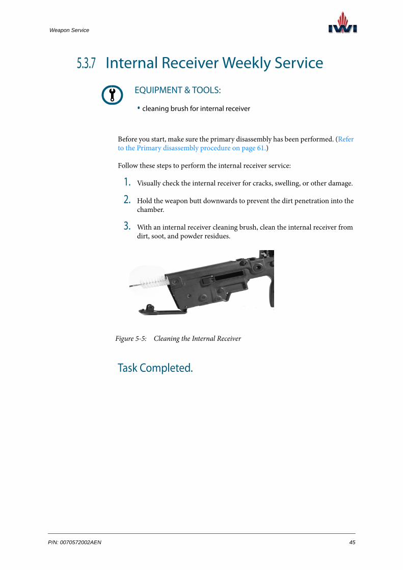
Weapon Service
5.3.7 Internal Receiver Weekly Service
Before you start, make sure the primary disassembly has been performed. (Refer to the Primary disassembly procedure on page 61.)
Follow these steps to perform the internal receiver service:
1. Visually check the internal receiver for cracks, swelling, or other damage.
2. Hold the weapon butt downwards to prevent the dirt penetration into the chamber.
3. With an internal receiver cleaning brush, clean the internal receiver from dirt, soot, and powder residues.
Figure 5-5: Cleaning the Internal Receiver
Task Completed.
EQUIPMENT & TOOLS:
• cleaning brush for internal receiver
P/N: 0070572002AEN 45
technical manual for X95® Chapter 5
5.3.8 Bolt Carrier Group Weekly Service in Assault Rifle Models
Before you start, make sure the secondary disassembly has been performed. (Refer to the Secondary disassembly in assault rifle models procedure on page 62.)
Follow these steps to perform the bolt carrier group weekly service:
1. With a dry clean patch, thoroughly clean the firing pin and the bolt guide pin.
2. With a dry clean patch, thoroughly clean soot and metal shavings from the bolt, paying special attention to the extractor and ejector areas.
3. Check the bolt surface for damage and verify that the firing pin hole is round and not eroded.
4. Verify that the firing pin hole is round and not eroded.
5. Check the ejector for normal springiness.
Task Completed.
NOTE: This procedure is applicable to assault rifle models only.
EQUIPMENT & TOOLS:
• none
46 Rev.: 1.0

Weapon Service
5.3.9 Sear Mechanism Monthly Service
Before you start, make sure the sear mechanism has been removed from the weapon. (Refer to the Removing the sear mechanism procedure on page 63.)
Follow these steps to perform the sear mechanism service:
1. With a clean patch, clean the mechanism housing and all accessible parts.
2. Slightly lubricate all the springs that can be accessed.
Figure 5-6: Lubricating the Sear Mechanism Springs
3. Check the sear mechanism springs for normal springiness.
Task Completed.
EQUIPMENT & TOOLS:
• rifle lubricant (oil/spray)
NOTE: Perform the procedure at least once every four months.
P/N: 0070572002AEN 47

technical manual for X95® Chapter 5
5.3.10 Safety Monthly Service
Follow these steps to perform the safety service:
1. Remove the safety from the weapon. (p. 128)
2. With dry, clean patch, thoroughly clean the safety.
3. Place a few drops of lubricant on a patch and lubricate the safety surface.
4. Install the safety inside the weapon. (p. 129)
5. Check the safety for proper operation.
Task Completed.
EQUIPMENT & TOOLS:
• rifle lubricant (oil/spray)
NOTE: Perform the procedure at least once every four months.
48 Rev.: 1.0

Weapon Service
5.3.11 Magazine Monthly Service
Follow these steps to perform the magazine service:
1. Make sure the magazine is empty.
2. With the aid of a small pointed object, remove the magazine base and pull out the follower.
EQUIPMENT & TOOLS:
• small pointed object
• rifle lubricant (oil/spray)
NOTE: Perform the procedure at least once every four months.
assault rifle models:
submachine gun models:
Figure 5-7: Disassembling the Magazine
P/N: 0070572002AEN 49
technical manual for X95® Chapter 5
3. With a clean dry patch, clean the follower spring.
4. Place a few drops of lubricant on a patch and slightly lubricate the fol-lower spring.
5. Reassemble the magazine.
6. Check the follower spring for normal springiness.
Task Completed.
50 Rev.: 1.0

Weapon Inspection
5.4 Weapon InspectionThe Weapon Inspection is carried out by ordnance personnel prior to issuing the weapon.
The following paragraphs detail the procedure for the inspection of the X95®.
5.4.1 General Assembly InspectionConduct the General Assembly Inspection as follows:
1. Verify the weapon completeness.
2. Pull the cocking handle to the rear and release it; verify proper and free movement of the weapon parts.
3. Set the fire selector to A (automatic) and pull the trigger.
Cock the weapon again and make sure the hammer is released.
4. Set the fire selector to R (semi-automatic), cock the weapon and release the trigger slowly, until you hear the release of the automatic sear.
Now, pull the trigger again and cock the weapon with the trigger still pulled. Verify that the trigger is not released.
Release the trigger—you should hear the reconnection click.
Pull the trigger and verify that the hammer is released.
5. Insert the magazine into the magazine well and verify it is held by the magazine catch.
6. Insert an empty magazine and cock the weapon. Verify that the recoiling system is held in the rear position.
7. Cock the weapon, set the fire selector to A (automatic), and pull the trig-ger.
Now, cock and release the sear mechanism. Verify that the hammer is released while the system is locked.
8. Cock the weapon and verify the ability to set the fire selector to S (safe).
9. Verify the ability to cock the weapon in the S (safe) mode.
10. Verify that the sear mechanism is not released in S (safe) mode.
P/N: 0070572002AEN 51

technical manual for X95® Chapter 5
11. Verify proper performance of the cocking mechanism by pulling the cocking handle to the rear.
With the recoiling system in the rear position, the cocked hammer must be stopped by the disconnector and sear.
12. For assault rifle models only: Verify proper locking of the bolt in the barrel extension.
13. Verify proper assembly of the backup sights.
14. Verify proper functioning of “Beta Lights” installed in the backup sights.
15. If applicable: Verify the flash suppressor tightening by a nut with 3.3-3.6 kg moment.
Task Completed.
5.4.2 Visual InspectionConduct the Visual Inspection as follows:
1. Verify the safety positions are distinct and accurate.
2. Verify there are no sharp edges.
3. Verify the proper appearance and quality of surface treatment without signs of corrosion.
4. Verify that the connection pins do not come out by hand force when pushed with a punch.
Task Completed.
52 Rev.: 1.0

Weapon Inspection
5.4.3 Functional Firing TestTo perform the Functional Firing Test on the X95®, install the weapon in a recoiled cradle and fire one full magazine in the semi-automatic and automatic modes. Verify the following:
• proper functioning of the trigger
• proper functioning of the sear mechanism (connecting & disconnecting)
• for assault rifle models only: full bolt locking
• proper feeding
• proper indent
• proper extraction
• proper ejection
• proper functioning of the fire selector during firing in the semi-auto-matic, automatic modes
• proper functioning of the fire selector in the safe mode
• no firing in the S (safe) position
• proper functioning of the last round catchThe recoiling parts stop in the rear position when the magazine is empty.
• cartridges undamaged
• concentricity of firing indent within ± 0.4
• rate of fire within the range of 700-1000 rd/min
• grouping at the range of 25 m
a. Fire five rounds to the POA (point of aiming)
b. Erase the deviated round.
c. Measure the ES (extreme spread):
If the weapon does not meet the ES requirements, fire another three groups of six rounds each.
Task Completed.
BACKUP SIGHTS INTEGRAL REFLEX SIGHT
ES ≤ 50 mm/25 m ≤ 50 mm/25 m
P/N: 0070572002AEN 53

technical manual for X95® Chapter 5
5.4.4 Accessories InspectionConduct the Accessories Inspection as follows:
Optical devices
• Verify the device completeness.
• Verify that the device is properly installed on the weapon.
• Verify the device proper operation.
• If applicable: Verify the laser switch operates properly.
Bayonet • Verify the bayonet completeness.
• Verify that the bayonet can be assembled on the weapon.
54 Rev.: 1.0

Maintenance Under Extreme Conditions
5.5 Maintenance Under Extreme Conditions
Under extreme conditions, perform service and cleaning as follows:
Cold climate At temperatures below the freezing point it is essential that all weapon-recoiling parts are moisture free. It is proved that over-lubrication of the metal parts causes coagulation that create loose operation of the mechanism and faults.
Thus, after carrying out the daily service, proceed as follows:
1. Dress the weapon with a muzzle cover.
2. Protect the weapon against rain and snow.
3. Upon completion of activities and when entering a building, dry and clean well the weapon and re-lubricate.
Task Completed.
EQUIPMENT & TOOLS:
• muzzle cover
• lubricant for low temperature
CAUTION! At temperatures below -10°C, disassemble the weapon down to user-authorized level and lubricate the metal parts with special low temperature oil.
P/N: 0070572002AEN 55

technical manual for X95® Chapter 5
Hot/humid climate
At high temperature and humid climate, service/inspect properly the weapon daily and after cleaning, lubricate the metal parts with rust preventive oil.
Sand storm
Under sand storm conditions, sand and dust may penetrate into the mechanism and bore. Sand, stuck to the lubricant may be a cause of faults.
Thus, thorough daily cleaning is essential. After using the weapon on sand grounds proceed as follows:
1. Wipe the weapon dry to prevent sand from sticking to the lubricant.
2. Protect the weapon with a muzzle cover to prevent sand and dust pene-trating into the bore.
3. Apply lubricant to the recoiling parts and sliding surfaces, such as the sliding surface between the bolt and the bolt carrier, bolt locking helix, and bolt carrier guide rod (in assault rifle models), return spring, cocking handle bar, and the slot of the cocking handle guide.
Task Completed.
EQUIPMENT & TOOLS:
• cleaning brush, general
• rifle lubricant (oil/spray)
• rust preventive oil
EQUIPMENT & TOOLS:
• muzzle cover
• rifle oil lubricant
56 Rev.: 1.0
Maintenance Before and After Firing
5.6 Maintenance Before and After Firing
This section lists the procedures for the pre/post-firing maintenance of the X95®.
Pre-firing inspection/service
Follow these steps to perform the pre-firing inspection/service:
1. Perform the primary disassembly (p. 61)
2. With a dry clean patch, remove soot, sand and oil.
3. Clean the barrel bore (p. 41).
4. Apply thin coat of lubricant to recoiling parts surfaces except for surfaces that contact exhaust gas such as the barrel bore or the chamber.
5. Assemble the weapon taking special care not to replace assemblies with those of another weapon.
Task Completed.
WARNING! Use standard ammunition approved by ammunition inspector. Do not lubricate or clean ammunition with any cleaning solvents.
EQUIPMENT & TOOLS:
• cleaning brush, general
• cleaning rod
• rifle lubricant (oil/spray)
DANGER! Prior to the procedure, make sure the weapon is unloaded. (p. 24).
P/N: 0070572002AEN 57

technical manual for X95® Chapter 5
Post-firing inspection/service
Carry out the inspection/service immediately after firing. When this is impossi-ble, lubricate the weapon parts and the barrel bore with thick coat of rifle oil to avoid curing of the soot.
Follow these steps to perform the post-firing inspection/service of the X95®:
1. Clean the weapon thoroughly, with special attention to parts contacting exhaust gas.
2. Perform the primary disassembly (p. 61)
3. Separate the weapon assemblies from each other.
4. Clean all weapon assemblies with standard cleaning solution.
5. Pass a patch moistened with rust preventive oil through the barrel bore. Repeat the step several times, each time with a new clean patch until the patch comes out clean.
6. Clean well and lubricate the barrel bore, chamber and gas system assem-blies daily until no soot comes out (minimum seven days).
7. Clean the feeding assembly from sand, dust, etc.
Task Completed.
EQUIPMENT & TOOLS:
• cleaning brush, general
• cleaning rod
• cleaning brush for chamber and barrel extension
• cleaning brush for internal receiver
• rifle lubricant (oil/spray)
• cleaning solution
DANGER! Make sure the weapon is unloaded. (p. 24).
58 Rev.: 1.0

CHAPTER 6
UNITDISASSEMBLY
This chapter contains procedures for unit disassembly of the X95®.
No disassembly/assembly activities are allowed to be performed by the user except for these detailed hereinafter. The user shall not remove or install any other part on the weapon and when necessary an authorized armorer shall be applied.
Reassembly is carried out same as disassembly, but in the reverse order.
P/N: 0070572002AEN 59

technical manual for X95® Chapter 6
6.1 General Instructions for Weapon Disassembly
The unit disassembly of the X95® includes the following procedures:
The following instructions are applicable both to the user and to various mainte-nance echelons:
• Prior to disassembly, carry out safety inspection and remove ammunition from the weapon.
• Place the parts according to the disassembly sequence on a clean surface to keep the parts clean.
• Use authorized accessories and tools only.
• Separate the parts of the weapon from other weapons parts.
• Use dry cleaning patch to clean the weapon parts.
assault rifle models:
1. primary disassembly
2. secondary disassembly
3. removing the sear mechanism
submachine gun models:
1. primary disassembly
2. removing the sear mechanism
60 Rev.: 1.0

Unit Disassembly Procedures
6.2 Unit Disassembly Procedures
This section details the procedures for unit disassembly of the X95®.
Primary disassembly
Perform the primary disassembly as follows:
1. Press the butt locking pin on the RH side of the weapon and pull all the way to the LH side (the pin remains connected to the weapon).
2. Open the butt holding its top section, pull the buffer and extract the mov-ing parts.
EQUIPMENT & TOOLS:
• none
Primary disassembly in assault rifle models:
Primary disassembly in submachine gun models:
Task Completed.
butt locking pin
butt locking pin
P/N: 0070572002AEN 61

technical manual for X95® Chapter 6
Primary reassembly
Reassemble the weapon in the reverse order to the primary disassembly.
Secondary disassembly in assault rifle models
Figure 6-1: Secondary Disassembly
NOTE: While reassembling the weapon, make sure that the bolt guide rod is in the forward position.
EQUIPMENT & TOOLS:
• none
# PART DESCRIPTION
1 return spring
2 bolt carrier guide rod
3 buffer
4 bolt guide pin
5 bolt
6 firing pin
1
2
3
4
5
6
62 Rev.: 1.0

Unit Disassembly Procedures
Perform the secondary disassembly as follows:
1. Compress the return spring (1) and remove it from the buffer (3).
2. Remove the bolt carrier guide rod (2). Push the bolt guide pin (4) at the bolt carrier RH side until it comes out of the bolt carrier.
3. Remove the bolt (5) and the firing pin (6) from the bolt carrier.
Task Completed.
Secondary reassembly
Perform the reassembly as follows:
Perform steps 1-3 in the reverse order.
Task Completed.
Removing the sear mechanism
Follow these steps to remove the sear mechanism:
1. Press the mechanism locking pins on the weapon RH side and pull them all the way to the weapon LH side. The mechanism locking pins remain connected to the weapon.
NOTE: While inserting the bolt guide pin, the bolt and the fir-ing pin grooves must be facing up and the bolt guide pin must enter its place in the bolt carrier sink.
NOTE: The best way to remove the mechanism is after you have removed the recoiling system.
P/N: 0070572002AEN 63

technical manual for X95® Chapter 6
2. Lift the last round catch lever and remove the sear mechanism.
Figure 6-2: Removing the Sear Mechanism
Reinstalling the sear mechanism
Reinstall the sear mechanism as follows:
Install the sear mechanism in the reverse order to the removal.
Task Completed.
mechanism locking pinsmechanism housing
NOTE: Make sure the hammer is cocked during the installation.
64 Rev.: 1.0
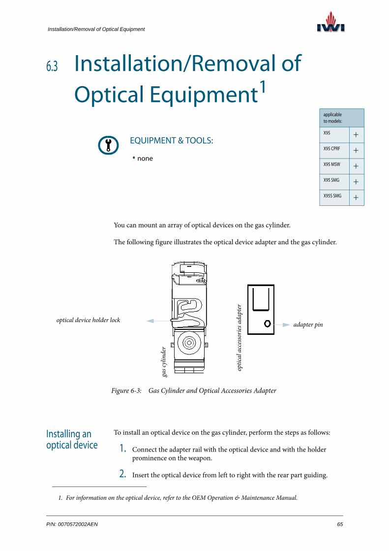
Installation/Removal of Optical Equipment
+
+
+
+
+
6.3 Installation/Removal of Optical Equipment1
You can mount an array of optical devices on the gas cylinder.
The following figure illustrates the optical device adapter and the gas cylinder.
Figure 6-3: Gas Cylinder and Optical Accessories Adapter
Installing an optical device
To install an optical device on the gas cylinder, perform the steps as follows:
1. Connect the adapter rail with the optical device and with the holder prominence on the weapon.
2. Insert the optical device from left to right with the rear part guiding.
1. For information on the optical device, refer to the OEM Operation & Maintenance Manual.
EQUIPMENT & TOOLS:
• none
applicable to models:
X95
X95 CPRF
X95 MSW
X95 SMG
X95S SMG
gas c
ylin
der
optic
al a
cces
sorie
s ada
pter
optical device holder lockadapter pin
P/N: 0070572002AEN 65

technical manual for X95® Chapter 6
3. Rotate the optical device to adapt (lock) into the pin adapter in the optical device holder - rotating counter-clockwise (view from above).
Figure 6-4: Installing the Optical Device on the Gas Cylinder
4. Verify the optical device is locked.
Task Completed.
Removing an optical device
Remove the optical device as follows:
Press on the strength lock in the holder backwards and rotate the optical device clockwise (while pressing on the lock).
Task Completed.
CAUTION! Since the assembling and disassembling of the optical device on the adapter is done from the same direction, excessive force can break the adapter.
66 Rev.: 1.0

Installation/Removal of the Bayonet
-
+
-
-
-
6.4 Installation/Removal of the Bayonet
Figure 6-5: Bayonet
Installing the bayonet
To install the bayonet on the flash suppressor, perform the steps as follows:
1. Hold the bayonet so that the slot on the bayonet handle faces the adapter lug on the flash suppressor.
2. Fit the bayonet on the adapter lug and slide onto the flash suppressor until it snaps into place.
Figure 6-6: Installing the Bayonet
Task Completed.
EQUIPMENT & TOOLS:
• none
applicable to models:
X95
X95 CPRF
X95 MSW
X95 SMG
X95S SMG
bayonet adapter
P/N: 0070572002AEN 67

technical manual for X95® Chapter 6
Removing the bayonet
To remove the bayonet from the weapon, press the button on the bayonet handle and slide the bayonet off the adapter lug.
Task Completed.
68 Rev.: 1.0

CHAPTER 7
FIELDDISASSEMBLY
This chapter contains reference to the tools and materials for weapon service and details the disassembly/reassembly procedures at Echelons A & B.
P/N: 0070572002AEN 69

technical manual for X95® Chapter 7
7.1 Tools and Materials for Weapon Service
The following tools and materials are used to perform disassembly and assembly tasks:
Table 7.1: Tools and Materials for Field Disassembly
1 Wrench, Allen
sizes:
• 2.00 mm
• 2.50 mm
• 3.00 mm
• 4.00 mm
• 1/8”
• 9/64”
2 Wrench, open (x2)
sizes:
• 19.00 mm or
• 3/4”
3 Wrench, closed hex
size:
7.00 mm
4 Wrench, barrel
5 Punch
sizes:
• 1.50 mm
• 2.00 mm
• 3.00 mm
70 Rev.: 1.0

Tools and Materials for Weapon Service
6 Pin guide
sizes:
• 1.50 mm
• 2.00 mm
7 Hammer, metal
8 Hammer, plastic
9 Screwdriver, 2x80, flat
10 Screwdriver, Phillips
11 Loctite adhesive
• 242
• 270
12 Pliers, sharp nose
13 Wrench, zeroing
14 Protective goggles
Table 7.1: Tools and Materials for Field Disassembly (Cont.)
P/N: 0070572002AEN 71

technical manual for X95® Chapter 7
7.2 Field Disassembly ProceduresThe following table provides model-specific reference to the procedures for Field Disassembly y of the X95®.
7.2.1. Flash Suppressor Disassembly at Echelon A. . . . . . . . . . . . . . . . . . . . . . . . . . . . . . . . . . . . . . . . . . 73
7.2.2. Integral Silencer Disassembly at Echelon A . . . . . . . . . . . . . . . . . . . . . . . . . . . . . . . . . . . . . . . . . . 75
7.2.3. Pistol Grip Disassembly at Echelon A. . . . . . . . . . . . . . . . . . . . . . . . . . . . . . . . . . . . . . . . . . . . . . . 77
7.2.4. Fore Grip Group Disassembly at Echelon A. . . . . . . . . . . . . . . . . . . . . . . . . . . . . . . . . . . . . . . . . . 79
7.2.5. Cocking Handle Bar Group Disassembly at Echelon A. . . . . . . . . . . . . . . . . . . . . . . . . . . . . . . . . 86
7.2.6. Barrel Group Disassembly at Echelon A. . . . . . . . . . . . . . . . . . . . . . . . . . . . . . . . . . . . . . . . . . . . . 89
7.2.7. Middle Swivel Disassembly at Echelon A . . . . . . . . . . . . . . . . . . . . . . . . . . . . . . . . . . . . . . . . . . . . 93
7.2.8. Trigger Disassembly at Echelon A. . . . . . . . . . . . . . . . . . . . . . . . . . . . . . . . . . . . . . . . . . . . . . . . . . 95
7.2.9. Butt Disassembly at Echelon A . . . . . . . . . . . . . . . . . . . . . . . . . . . . . . . . . . . . . . . . . . . . . . . . . . . . 98
7.2.10. Last Round Catch Group Disassembly at Echelon A . . . . . . . . . . . . . . . . . . . . . . . . . . . . . . . . . 100
7.2.11. Outer Receiver Group Disassembly at Echelon A . . . . . . . . . . . . . . . . . . . . . . . . . . . . . . . . . . . . 103
7.2.12. Magazine Adapter Disassembly at Echelon A . . . . . . . . . . . . . . . . . . . . . . . . . . . . . . . . . . . . . . . 110
7.2.13. Breech Block Group Disassembly in Submachine Gun Models at Echelon A . . . . . . . . . . . . . . 112
7.2.14. Bolt Carrier Group Disassembly at Echelons A & B . . . . . . . . . . . . . . . . . . . . . . . . . . . . . . . . . . 115
7.2.15. Gas Cylinder Disassembly at Echelons A & B . . . . . . . . . . . . . . . . . . . . . . . . . . . . . . . . . . . . . . . 122
7.2.16. Safety Group Disassembly at Echelon B . . . . . . . . . . . . . . . . . . . . . . . . . . . . . . . . . . . . . . . . . . . . 126
7.2.17. Sear Mechanism Disassembly at Echelon B . . . . . . . . . . . . . . . . . . . . . . . . . . . . . . . . . . . . . . . . . 130
72 Rev.: 1.0

Field Disassembly Procedures
+
+
+
+
-
7.2.1 Flash Suppressor Disassembly at Echelon A
Figure 7-1: Flash Suppressor Parts
Disassembling the flash suppressor
To disassemble the flash suppressor, perform the steps as follows:
1. Hold the flash suppressor (1) and the suppressor locking nut (2) using the wrenches.
2. Turn the flash suppressor (1) counter-clockwise while turning the sup-pressor locking nut (2) clockwise;
EQUIPMENT & TOOLS:
• wrench 19 mm x2 or wrench 3/4’’ x2
# PART NUMBER PART DESCRIPTION
1 007042010 flash suppressor, models X95, X95 MSW, X95 SMG
2 007262006 flash suppressor, model X95 CPRF
3 007042008 locking nut, suppressor
4 007050143 swivel, front
applicable to models:
X95
X95 CPRF
X95 MSW
X95 SMG
X95S SMG
1
2 3
4
P/N: 0070572002AEN 73

technical manual for X95® Chapter 7
3. Remove the flash suppressor (1), unscrew the suppressor locking nut (2), and remove the front swivel (3).
Figure 7-2: Removing the Flash Suppressor
Task Completed.
Reassembling the flash suppressor
To reassemble the flash suppressor, perform the steps as follows:
1. Fit the front swivel (3) on the barrel.
2. Screw the suppressor locking nut (2) to the barrel until the end of the thread.
3. Screw the flash suppressor (1) until it touches its locking nut (2); then unscrew the flash suppressor until its slots point up.
4. Using one wrench, hold the flash suppressor (1) in place, using the other wrench, tighten the suppressor locking nut (2) counter-clockwise against the flash suppressor.
Task Completed.
74 Rev.: 1.0

Field Disassembly Procedures
-
-
-
-
+
7.2.2 Integral Silencer Disassembly at Echelon A
Figure 7-3: Silencer
Disassembling the silencer
To disassemble the silencer, proceed as follows:
Turn the silencer counter-clockwise and remove it from the barrel.
Task Completed.
Reassembling the silencer
To reassemble the silencer, perform the steps as follows:
1. Screw the silencer to the barrel.
EQUIPMENT & TOOLS:
• silencer centrality gauge
# PART NUMBER PART DESCRIPTION
1 10900295 silencer
applicable to models:
X95
X95 CPRF
X95 MSW
X95 SMG
X95S SMG
P/N: 0070572002AEN 75

technical manual for X95® Chapter 7
2. With the silencer centrality gauge, conduct the silencer centrality inspec-tion.
Figure 7-4: Silencer Straightness Inspection
Task Completed.
76 Rev.: 1.0

Field Disassembly Procedures
+
+
+
+
+
7.2.3 Pistol Grip Disassembly at Echelon A
Figure 7-5: Pistol Grip Parts
EQUIPMENT & TOOLS:
• screwdriver, Phillips
• Allen wrench, 2.50 mm
# PART NUMBER PART DESCRIPTION
1 007051086 x2 attachment screw, side plate
2 007051083 side plate, RH
3 007051087 pistol grip
4 007051082 side plate, LH
5 007051084 attachment screw, pistol grip
applicable to models:
X95
X95 CPRF
X95 MSW
X95 SMG
X95S SMG
1
1
2
3
45
P/N: 0070572002AEN 77

technical manual for X95® Chapter 7
Disassembling the pistol grip
To disassemble the pistol grip, perform the steps as follows:
1. With a Phillips screwdriver, release the pistol grip attachment screw (5) and remove the pistol grip (3).
Figure 7-6: Releasing the Pistol Grip Attachment Screw
2. With a 2.5 mm Allen wrench, release the side plate attachment screws (1) from both sides of the pistol grip and remove the RH side plate (2) and the LH side plate (4).
Figure 7-7: Releasing the Side Plate Attachment Screw
Task Completed.
Reassembling the pistol grip
To reassemble the pistol grip, perform the steps as follows:
1. Place the each side plate (2, 4) on the matching side of the pistol grip (3).
2. With a 2.5 Allen wrench, tighten the side plate attachment screws (1).
3. Insert the pistol grip (3) in its place in the receiver.
4. Insert the pistol grip attachment screw (5) and tighten it with a Phillips screwdriver.
Task Completed.
78 Rev.: 1.0

Field Disassembly Procedures
+
+
+
+
+
7.2.4 Fore Grip Group Disassembly at Ech-elon A
Figure 7-8: Grip Group
EQUIPMENT & TOOLS:
• punch, 1.50 mm
• Allen wrench, 2.00 mm
• Allen wrench, 3.00 mm
• screwdriver, Phillips
• screwdriver, flat
• hammer, metal
• pin guide
applicable to models:
X95
X95 CPRF
X95 MSW
X95 SMG
X95S SMG
19 20
12 3
4
56
7
89 10
11
11
121213
13
12
12
1313
14
14 15
16
1718
P/N: 0070572002AEN 79

technical manual for X95® Chapter 7
Disassembling the fore grip group
To disassemble the fore grip group, perform the steps as follows:
1. Remove the fore grip group from the weapon as follows:
a. Remove the pistol grip (p. 77).
# PART NUMBER PART DESCRIPTION
1 007040123 plunger, elevation
2 007040122 spring, elevation plunger
3 007040130 blade unit, front sight
4 007050121 bar, front sight
5 007040102 leaf spring, front sight
6 007040103 spring, front sight
7 007043107 safety pin, 1.5 mm
8 007040104 plunger, windage screw
9 007040105 spring, windage screw plunger
10 007040101 screw, windage
11 007051099 x2 cover, laser designator PTT
12 007051094 x4 connecting screw, Picatinny adapter
13 007051095 x4 (x2 for X95 CPRF) lockwasher
14 007051092 x2 Picatinny adapter for fore grip
15 007051091 fore grip
16 007050144 Teflon sleeve, front sight
17 007050001 adapter screw, fore grip
18 031200010 assault handle (X95, X95 MSW, X95S, X95 SMG)
19 007050142 sleeve, stabilizer (X95, X95 MSW, X95 SMG, X95 CRPF)
20 007050141 stabilizer, front sight (X95, X95 MSW, X95 SMG, X95 CRPF)
21 007050035 support, laser designator (X95 CRPF)
80 Rev.: 1.0

Field Disassembly Procedures
b. With a 3 mm Allen wrench, release the fore grip adapter screw (17).
Figure 7-9: Releasing the Fore Grip Adapter Screw
c. Release the assault handle locking screw and remove the assault handle (18).
Figure 7-10: Releasing the Assault Handle Locking Screw
d. Slide the fore grip group forward and remove the following parts from the weapon:
• fore grip unit (15)• sight stabilizer (20)• sight stabilizer sleeve (19)• Teflon sleeve (16)• laser designator PTT covers (11)
P/N: 0070572002AEN 81

technical manual for X95® Chapter 7
2. Remove the windage screw as follows:
a. On the cocking handle LH side, align the safety pin (7) with the groove on the projection ring and remove the safety pin using a 1.5 mm punch.
Figure 7-11: Removing the Safety Pin
b. With a flat screwdriver, rotate the windage screw (10) counter-clock-wise and then pull the windage screw to remove the following parts from the fore grip:
• front sight bar unit (4)• front sight spring (6)• front sight leaf spring (5)• windage screw plunger (8)• windage screw plunger spring (9)
Figure 7-12: Releasing the Windage Screw
3. With a 2 mm punch, press the elevation plunger (1) and rotate the front sight bar (4) counter-clockwise, to disassemble the front sight unit into the following parts:
82 Rev.: 1.0

Field Disassembly Procedures
• elevation plunger (1)• elevation plunger spring (2)
Figure 7-13: Disassembling the Front Sight Unit
4. Remove each of the Picatinny adapters as follows:
a. With a Phillips screwdriver, release the two Picatinny adapter connect-ing screws (12).
Figure 7-14: Releasing the Picatinny Adapter Connecting Screw
b. Remove the lockwashers (13).
c. Remove the Picatinny adapter (14) from the fore grip (15).
5. (For X95 CRPF) With a Phillips screwdriver, release the two connecting screws (12) and remove the laser designator PTT support (20).
Task Completed.
Reassembling the fore grip group
To reassemble the fore grip group, perform the steps as follows:
P/N: 0070572002AEN 83

technical manual for X95® Chapter 7
1. Assemble the front sight as follows:
a. Install the elevation plunger (1) and the elevation plunger spring (2) into the smooth hole in the front sight bar so that the smaller diameter of the plunger points up.
b. With a 2 mm punch, press the elevation plunger (1) and screw the blade unit (3) into the front sight bar (4) clockwise.
2. Install the front sight on the fore grip as follows:
a. Insert the front sight spring (6) and the leaf spring (5) into place.
Figure 7-15: Installing the Front Sight Spring and the Leaf Spring
b. Insert the windage screw plunger spring (9) and the windage screw plunger (8) into place.
Figure 7-16: Installing the Windage Screw Plunger Spring and the Windage Plunger
c. Place the front sight unit into its final location.
d. With a flat screwdriver, tighten the windage screw (10).
e. Align the hole on the end of the windage screw (10) with the groove on the projection ring.
f. Insert the safety pin (7) into place.
3. Install each of the Picatinny adapters as follows:
a. Place the Picatinny adapter (14) on the fore grip (15) and insert the two lockwashers (13) into place.
84 Rev.: 1.0

Field Disassembly Procedures
b. With a Phillips screwdriver, tighten the two Picatinny adapter con-necting screws (12).
4. (For X95 CRPF) Install the laser designator PTT support (20) in its place; insert the connecting screws (12) and tighten with a Phillips screwdriver.
5. Install the fore grip group on the weapon as follows:
a. Install the Teflon sleeve (16) in its place.
b. (If applicable) Install the sight stabilizer (20) in its place on the fore grip (15).
c. (If applicable) Insert the sight stabilizer sleeve (19) into the sight stabi-lizer.
d. Slide the fore grip group all the way onto the barrel.
e. With a 3 mm Allen wrench, tighten the fore grip adapter screw (17).
f. (If applicable) Install the assault handle (18) on the lower Picatinny adapter.
Task Completed.
P/N: 0070572002AEN 85

technical manual for X95® Chapter 7
applicablto models
X95
X95 CPRF
X95 MSW
X95 SMG
X95S SMG
7.2.5 Cocking Handle Bar Group Disassembly at Echelon A
Figure 7-17: Cocking Handle Bar Group
EQUIPMENT & TOOLS:
• punch 3.00 mm
• hammer, metal
# PART NUMBER PART DESCRIPTION
1 007050011 bar, cocking handle
2 007050016 cup, cocking handle
3 007050017 lever, cocking handle
4 007050008 handle, cocking
5 007040022 pin, cocking handle lever
6 007040002 x2 pin, general
e :
+
+
+
+
+
1
2
34
5
6
6
86 Rev.: 1.0

Field Disassembly Procedures
Disassembling the cocking handle bar
To disassemble the cocking handle bar, perform the steps as follows:
1. Pull the cocking handle bar (1) out of the receiver.
Figure 7-18: Extracting the Cocking Handle Bar from the Receiver
2. With a metal hammer and a 3 mm punch, remove the general pin (6) that secures the cocking handle (4) to the cocking handle cup (2) and separate the cocking handle.
Figure 7-19: Detaching the Cocking Handle from the Cocking Handle Lever
P/N: 0070572002AEN 87

technical manual for X95® Chapter 7
3. With a metal hammer and a 3 mm punch, remove the general pin (6) and the cocking handle lever pin (5) and disassemble the cocking handle bar unit into the following parts:
• cocking handle bar (1)• cocking handle cup (2)• cocking handle lever (3)
Figure 7-20: Disassembling the Cocking Handle Bar
Task Completed.
Reassembling the cocking handle bar
To reassemble the cocking handle bar, perform the steps as follows:
1. Insert the cocking handle lever (3) into the cocking handle cup (2).
2. With a metal hammer, secure the cocking handle lever pin (5).
3. Insert the cocking handle cup (2) into the cocking handle (4).
4. Insert the cocking handle bar (1) into the cocking handle cup (2).
5. With a metal hammer, insert the general pin (6) to secure the cocking handle cup (2) to the cocking handle (3).
6. With a metal hammer, insert the general pin (6) to secure the cocking handle cup (2) to the cocking handle bar (1).
7. Slide the cocking handle bar into its rail in the receiver.
Task Completed.
cocking handle lever pin general pin
88 Rev.: 1.0

Field Disassembly Procedures
+
+
+
+
+
7.2.6 Barrel Group Disassembly at Echelon A
Figure 7-21: Barrel Group
EQUIPMENT & TOOLS:
• barrel wrench
• punch, 1.50 mm
• punch, 2.00 mm
• sharp nose pliers
# PART NUMBER PART DESCRIPTION
1 N/A barrel, group, models X95, X95 MSW, X95 CPRF
2 N/A barrel group, model X95 SMG
3 N/A barrel, group, model X95S SMG
applicable to models:
X95
X95 CPRF
X95 MSW
X95 SMG
X95S SMG
1
2
3
P/N: 0070572002AEN 89

technical manual for X95® Chapter 7
Disassembling the barrel
To disassemble the barrel, perform the steps as follows:
1. With a 2 mm punch, unlock the plate covering the barrel locking pin (2).
Figure 7-22: Unlocking the Covering Plate of the Barrel Locking Pin
2. On the weapon RH side, insert the barrel wrench into the slot on the bar-rel locking pin (2).
While pressing the barrel locking pin plate on the LH side, unlock the barrel (1) by turning the barrel wrench 180° clockwise, so that the white mark is aligned with "O".
Pull the barrel (1) out of the receiver.
Figure 7-23: Unlocking the Barrel
WARNING! Verify that the cocking handle has been removed from the weapon. (p. 87).
barrel unlocked
90 Rev.: 1.0

Field Disassembly Procedures
3. Separate the front shield from the gas cylinder.
Figure 7-24: Separating the Front Shield from the Gas Cylinder
Task Completed.
Reassembling the barrel
To reassemble the barrel, perform the steps as follows:
1. Position the front shield on the gas cylinder according to the shooter con-figuration, so that the cocking handle bar is coaxial with its hole on the front shield.
Figure 7-25: Cocking Handle Bar Inside the Front Shield Hole
models with integral reflex sight:
models with detachable optical sight:
front shield
front shield
CAUTION! Verify that the white mark on the barrel locking pin is aligned with “O”. Verify that the front shield is installed properly, according to the shooter configuration.
cocking handle bar
front shield
P/N: 0070572002AEN 91

technical manual for X95® Chapter 7
2. Position the barrel (1) in its place in the receiver; insert the barrel wrench into the barrel locking pin and turn it 180° counter-clockwise, so that the white mark becomes aligned with “L' and the barrel locking pin (2) clicks into the notch in the receiver.
Figure 7-26: Barrel Locked
Task Completed.
92 Rev.: 1.0

Field Disassembly Procedures
+
+
+
+
+
7.2.7 Middle Swivel Disassembly at Echelon A
Figure 7-27: Middle Swivel Parts
Disassembling the middle swivel
To disassemble the middle swivel, perform the steps as follows:
1. With a punch, pull out the middle swivel spring (3) that secures the sling swivel lock (2).
Figure 7-28: Removing the Swivel Lock Spring
EQUIPMENT & TOOLS:
• punch, 2.00 mm
• sharp nose pliers
# PART NUMBER PART DESCRIPTION
1 007051036 swivel, middle
2 007051037 lock, middle swivel
3 007051038 spring, middle swivel
applicable to models:
X95
X95 CPRF
X95 MSW
X95 SMG
X95S SMG1
2
3
P/N: 0070572002AEN 93

technical manual for X95® Chapter 7
2. Unscrew the sling swivel lock (2) and the sling swivel (1).
Figure 7-29: Unscrewing the Swivel
Task Completed.
Reassembling the middle swivel
To reassemble the middle swivel, perform the steps as follows:
1. Insert the swivel (1) into its place on the weapon LH side (for RH config-uration) and screw it to the swivel lock (2).
2. Align the holes of the swivel (1) and the swivel lock (2).
Figure 7-30: Aligning the Holes of the Middle Swivel and Its Lock
3. With your finger or sharp nose pliers, insert the swivel securing spring (3) into place.
Task Completed.
swivel lock swivel
94 Rev.: 1.0

Field Disassembly Procedures
+
+
+
+
+
7.2.8 Trigger Disassembly at Echelon A
Figure 7-31: Trigger Unit
Disassembling the trigger
To disassemble the trigger, perform the steps as follows:
CAUTION! Do not disassemble the trigger unit beyond what is prescribed in this manual! The full assembly of the trigger unit includes riv-eting and is carried out by qualified ordnance personnel at Echelon B+ (Base repair).
EQUIPMENT & TOOLS:
• punch, 3.00 mm
• hammer, plastic
• protective goggles
# PART NUMBER PART DESCRIPTION
1 007051070 trigger unit
applicable to models:
X95
X95 CPRF
X95 MSW
X95 SMG
X95S SMG
trigger safety device
WARNING! The trigger unit contains a compressed spring that may shoot off upwards during the disassembly. Make sure you wear protective goggles to protect your eyes.
P/N: 0070572002AEN 95

technical manual for X95® Chapter 7
1. Separate the trigger safety device from the trigger bar.
Figure 7-32: Separating the Trigger Safety Device from the Trigger Bar
2. With a hammer and a 3.5 mm punch, remove the trigger pivot from the receiver RH side.
Figure 7-33: Removing the Trigger Pivot
3. Remove the trigger unit from the receiver.
Task Completed.
Reassembling the trigger
To reassemble the trigger, perform the steps as follows:
1. Install the trigger unit inside the weapon receiver as follows:
WARNING! Support the weapon from below to prevent the trigger spring from shooting off.
trigger safety device
trigger bar
96 Rev.: 1.0

Field Disassembly Procedures
a. Position the trigger in the receiver.
b. Through the trigger spring, insert a 3 mm punch into the trigger and verify that the trigger spring is installed properly.
Figure 7-34: Trigger Spring Supported by the Projection on the Receiver
c. Align the hole of the trigger with the hole of the receiver and insert the trigger pivot, sharp edge forwards, from the weapon RH side.
d. With a hammer, insert the trigger pivot into its final position.
e. With a punch, lightly press the trigger pivot to make sure that the trig-ger spring secures the trigger pivot.
f. Verify that the trigger safety device is not stuck on the trigger bar.
2. Pull the trigger several times to verify proper movement.
Task Completed.
NOTE: The protrusion on the trigger safety device must enter the corresponding hole in the trigger bar and the trigger spring must be supported by the projection on the receiver.
trigger spring
P/N: 0070572002AEN 97

technical manual for X95® Chapter 7
applicablto models
X95
X95 CPRF
X95 MSW
X95 SMG
X95S SMG
7.2.9 Butt Disassembly at Echelon A
Figure 7-35: Butt Parts
Disassembling the butt
To disassemble the butt, perform the steps as follows:
1. Pull the butt locking pin all the way out from the receiver LH side, until it is captured by the butt locking spring.
EQUIPMENT & TOOLS:
• screwdriver, flat x2
• punch, 5.00 mm
• Loctite 242 (or similar) adhesive
# PART NUMBER PART DESCRIPTION
1 007051200 butt unit
2 007040005 pivot, butt
3 007040006 screw, butt pivot
e :
+
+
+
+
+
1
2
3
98 Rev.: 1.0

Field Disassembly Procedures
With two flat screwdrivers, release the butt pivot screw (3) and remove the butt unit (1) and butt pivot (2).
Figure 7-36: Releasing the Butt Pivot Screw
Task Completed.
Reassembling the butt
To reassemble the butt, perform the steps as follows:
1. Insert the butt (1) into the receiver and align the holes of the butt with the holes of the receiver.
2. Insert the butt pivot (2) into its place.
3. Apply a thin coat of Loctite 242 to the butt pivot screw (3) and screw it in place.
4. Close the butt (1) and push the butt locking pin all the way in.
Task Completed.
butt locking pin
NOTE: Do not push the butt locking pin inside until you install the butt.
P/N: 0070572002AEN 99

technical manual for X95® Chapter 7
applicablto models
X95
X95 CPRF
X95 MSW
X95 SMG
X95S SMG
7.2.10 Last Round Catch Group Disassembly at Echelon A
Figure 7-37: Last Round Catch Parts
Disassembling the last round catch
To disassemble the last round catch, perform the steps as follows:
1. Verify that the bolt carrier/breech block group has been removed from the receiver. (Refer to the Primary disassembly procedure on page 61.)
EQUIPMENT & TOOLS:
• punch, 5.00 mm
# PART NUMBER PART DESCRIPTION
1 007041022 catch, last round (X95, X95 MSW, X95 SMG, X95S)
2 007261022 catch, last round (X95 CRPF)
3 007051025 lever, last round catch
4 007041024 spring, last round catch
5 007051023 pin, last round catch
e :
+
+
+
+
+
1
23
4
100 Rev.: 1.0

Field Disassembly Procedures
2. Open the mechanism locking pins on the receiver RH side and pull them all the way to the LH side.
Figure 7-38: Opening the Mechanism Locking Pins
3. Pull out the sear mechanism from the receiver.
4. Push the last round catch lever (2) inside the receiver and then remove the last round catch unit (1).
Figure 7-39: Removing the Last Round Catch
5. With a 5 mm punch, push out the last round catch pin (4); remove the last round catch spring (3) and separate the last round catch (1) from the last round catch lever (2).
Figure 7-40: Disassembling the Last Round Catch Group
Task Completed.
P/N: 0070572002AEN 101

technical manual for X95® Chapter 7
Reassembling the last round catch
To reassemble the last round catch, perform the steps as follows:
1. Position the last round catch spring (3) inside the last round catch (1) so that the spring long arm rests against the catch front wall, the spring short arm is behind the catch, and the holes of the catch are aligned with the loop of the spring.
Figure 7-41: Installing the Last Round Catch Spring Inside the Last Round
Catch
2. Install the last round catch unit inside the last round catch lever (2) as fol-lows:
a. Place the last round catch unit inside the last round catch lever so that the short arm of the last round catch spring enters the corresponding hole on the lever and the holes of the catch are aligned with those of the lever.
Figure 7-42: Positioning the Last Round Catch Unit Inside the Last Round Catch Lever
b. With a 4 mm punch and a metal hammer, install the last round catch pin (4) to secure the last round catch group in place.
3. Insert the last round catch group against the receiver rails into the receiver and pull it to its final location.
Task Completed.
last round catch spring long armlast round catch spring short arm
102 Rev.: 1.0

Field Disassembly Procedures
+
+
+
+
+
7.2.11 Outer Receiver Group Disassembly at Echelon A
Figure 7-43: Outer Receiver Group
EQUIPMENT & TOOLS:
• punch, 1.50 mm
• punch 2.00 mm
• punch, 5.00 mm
• hammer, plastic
• Allen wrench, 2.50 mm
• Allen wrench, 9/64’’
• screwdriver, Phillips
• screwdriver, flat
• sharp nose pliers
applicable to models:
X95
X95 CPRF
X95 MSW
X95 SMG
X95S SMG
12
34
4
566
7
54
4
7 66
88
9 910
11
15
16
1717
18
19
20
21
12
13
14
5
P/N: 0070572002AEN 103

technical manual for X95® Chapter 7
# PART NUMBER PART DESCRIPTION
1 007051114 frame, deflector (assault rifle models)
2 007041127 tightening screw, deflector
3 007051112 deflector
4 007041114 x4 screw, extraction port shield
5 007041112 x2 shield, extraction port
6 007041113 x4 nut, extraction port shield
7 007041126 tightening nut, deflector
8 007041012 x2 locking pin, mechanism
9 007041105 x2 spring, mechanism locking pin
10 007041013 cover, ejection port
11 007041014 base, ejection port cover
12 007041032 locking pin, butt
13 007041033 spring, butt locking pin
14 007041040 locking pin, barrel
15 007051004 lever, LH, magazine release
16 007051005 lever, RH, magazine release
17 007051006 x2 pivot, magazine release
18 007051008 retaining spring, magazine release pivot
19 007051010 catch, magazine
20 007051003 pivot, magazine catch
21 007051002 spring, magazine catch
104 Rev.: 1.0

Field Disassembly Procedures
Disassembling the outer receiver group
To disassemble the outer receiver group, perform the steps as follows:
1. Disassemble the magazine release as follows:
a. With a flat screwdriver, push out the magazine release pivot spring (18).
Figure 7-44: Removing the Magazine Release Pivot Retaining Spring
b. With sharp nose pliers, pull out the magazine release pivots (17).
Figure 7-45: Removing a Magazine Release Pivot
c. Remove the magazine release RH lever (16) and LH lever (15).
P/N: 0070572002AEN 105

technical manual for X95® Chapter 7
2. Disassemble the magazine catch as follows:
a. With a 2.5 mm punch and a hammer, push out the magazine catch pivot (20).
Figure 7-46: Removing the Magazine Catch Pivot
b. Hold the magazine catch (19) and the magazine catch spring (21) and take out the punch.
3. Disassemble the deflector group as follows:
a. With a 9/64’’ Allen wrench, release the deflector tightening screw (2).
Figure 7-47: Releasing the Deflector Tightening Screw
assault rifle models:
submachine gun models:
106 Rev.: 1.0
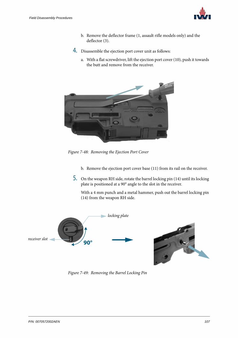
Field Disassembly Procedures
b. Remove the deflector frame (1, assault rifle models only) and the deflector (3).
4. Disassemble the ejection port cover unit as follows:
a. With a flat screwdriver, lift the ejection port cover (10), push it towards the butt and remove from the receiver.
Figure 7-48: Removing the Ejection Port Cover
b. Remove the ejection port cover base (11) from its rail on the receiver.
5. On the weapon RH side, rotate the barrel locking pin (14) until its locking plate is positioned at a 90° angle to the slot in the receiver.
With a 4 mm punch and a metal hammer, push out the barrel locking pin (14) from the weapon RH side.
Figure 7-49: Removing the Barrel Locking Pin
90°
locking plate
receiver slot
P/N: 0070572002AEN 107
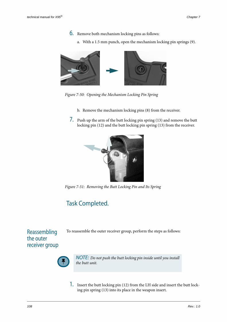
technical manual for X95® Chapter 7
6. Remove both mechanism locking pins as follows:
a. With a 1.5 mm punch, open the mechanism locking pin springs (9).
Figure 7-50: Opening the Mechanism Locking Pin Spring
b. Remove the mechanism locking pins (8) from the receiver.
7. Push up the arm of the butt locking pin spring (13) and remove the butt locking pin (12) and the butt locking pin spring (13) from the receiver.
Figure 7-51: Removing the Butt Locking Pin and Its Spring
Task Completed.
Reassembling the outer receiver group
To reassemble the outer receiver group, perform the steps as follows:
1. Insert the butt locking pin (12) from the LH side and insert the butt lock-ing pin spring (13) into its place in the weapon insert.
NOTE: Do not push the butt locking pin inside until you install the butt unit.
108 Rev.: 1.0

Field Disassembly Procedures
2. Assemble the magazine release unit as follows:
a. Install the magazine release RH lever (16) in its place.
b. Install the magazine release LH lever (15) in its place.
c. Insert both magazine release pivots (17) into place through the holes in the magazine release levers.
d. Install the magazine release pivot retaining spring (18) in its place.
3. Assemble the magazine catch as follows:
a. Insert the magazine catch spring (21) into the magazine catch (19).
b. Insert the magazine catch pivot (20) into the receiver so that the small diameter enters first.
c. With a 2.5 mm punch and a hammer, push the magazine catch pivot (20) all the way into the receiver.
4. Assemble the deflector group as follows:
a. For assault rifle models: Install the deflector frame (1) on the ejection port on the weapon RH side (RH configuration) or LH side (LH con-figuration). Connect the deflector (3) to the deflector frame (1).For submachine gun models: Install the deflector (3) on the extraction port shield on the weapon RH side (RH configuration) or LH side (LH configuration).
b. With a 9/64’’ Allen wrench, tighten the deflector tightening screw (2).
5. Install the ejection port cover base (11) on its rail and install the ejection port cover (10) on the base.
6. On the weapon LH side, insert the barrel locking pin (14) against the receiver slot; push the barrel locking pin (14) inside the receiver and rotate clockwise.
7. Install the mechanism locking pins as follows:
a. With a 1.5 mm punch, install the mechanism locking pin springs (9).
Figure 7-52: Installing the Mechanism Locking Pin Spring
b. Insert the mechanism locking pins (8) into their place on the weapon receiver.
Task Completed.
P/N: 0070572002AEN 109

technical manual for X95® Chapter 7
applicablto models
X95
X95 CPRF
X95 MSW
X95 SMG
X95S SMG
7.2.12 Magazine Adapter Disassembly at Echelon A
Figure 7-53: Magazine Adapter Parts
NOTE: This procedure is applicable to submachine gun models only.
EQUIPMENT & TOOLS:
• punch, 4.00 mm
• hammer, metal
# PART NUMBER PART DESCRIPTION
1 007155011 adapter group, magazine
2 007155016 x2 attachment pin
e :
-
-
-
+
+
12
2
110 Rev.: 1.0
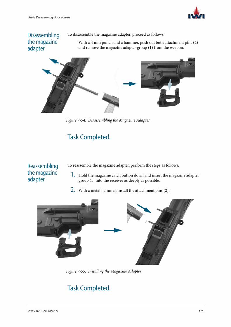
Field Disassembly Procedures
Disassembling the magazine adapter
To disassemble the magazine adapter, proceed as follows:
With a 4 mm punch and a hammer, push out both attachment pins (2) and remove the magazine adapter group (1) from the weapon.
Figure 7-54: Disassembling the Magazine Adapter
Task Completed.
Reassembling the magazine adapter
To reassemble the magazine adapter, perform the steps as follows:
1. Hold the magazine catch button down and insert the magazine adapter group (1) into the receiver as deeply as possible.
2. With a metal hammer, install the attachment pins (2).
Figure 7-55: Installing the Magazine Adapter
Task Completed.
P/N: 0070572002AEN 111

technical manual for X95® Chapter 7
applicablto models
X95
X95 CPRF
X95 MSW
X95 SMG
X95S SMG
7.2.13 Breech Block Group Disassembly in Submachine Gun Models at Echelon A
Figure 7-56: Breech Block Group
EQUIPMENT & TOOLS:
• punch, 3.00 mm
• hammer, metal
• screwdriver, flat
# PART NUMBER PART DESCRIPTION
1 007153304 pipe, piston
2 007153306 x2 pin, extractor
3 007153221 buffer
4 007043307 pin, piston pipe
5 007153001 pin, firing
6 007153308 spring, firing pin
7 007153302 extractor
8 007153307 counter pin, extractor
e :
-
-
-
+
+1 2
2
3
4
5
6
7
8
112 Rev.: 1.0

Field Disassembly Procedures
Disassembling the breech block group
To disassemble the breech block group, perform the steps as follows:
1. Compress the return spring and separate the buffer (3) from the return spring guide.
2. Push the piston pipe pin (4) at the breech block LH side until it comes out of the breech block.
3. On the breech block LH side, press the extractor back pin (2) and remove it from the breech block.
Figure 7-57: Removing the Extractor Back Pin
4. Rotate the firing pin (5) 180° clockwise and pull out the firing pin (5) and the firing pin spring (6) from the breech block.
Figure 7-58: Removing the Firing Pin
5. With a hammer and a 3 mm punch, press the extractor front pin (2) and remove it from the breech block.
Figure 7-59: Removing the Extractor Front Pin
P/N: 0070572002AEN 113

technical manual for X95® Chapter 7
6. With a flat screwdriver, seize the extractor (7) by its notch and pull the extractor and the extractor counter pin (8) out of the breech block.
Figure 7-60: Removing the Extractor
Task Completed.
Reassembling the breech block group
To reassemble the breech block group, perform the steps as follows:
1. Install the extractor (7) and the extractor counter pin (8) in their place inside the breech block.
2. With a hammer and a 3 mm punch, insert the extractor front pin (2).
3. Insert the firing pin spring (6) and the firing pin (5) into their place inside the breech block.
4. With a hammer and a 3 mm punch, insert the extractor back pin (2).
5. Install the buffer (3) on the return spring guide.
Task Completed.
NOTE: The surfaces of the general pin, extractor back pin, and extractor pin must be flush with the breech block side wall.
114 Rev.: 1.0
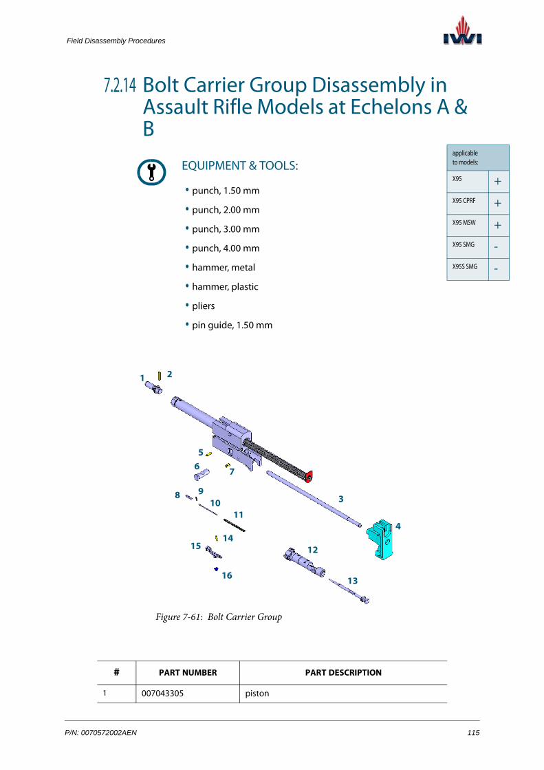
Field Disassembly Procedures
+
+
+
-
-
7.2.14 Bolt Carrier Group Disassembly in Assault Rifle Models at Echelons A & B
Figure 7-61: Bolt Carrier Group
EQUIPMENT & TOOLS:
• punch, 1.50 mm
• punch, 2.00 mm
• punch, 3.00 mm
• punch, 4.00 mm
• hammer, metal
• hammer, plastic
• pliers
• pin guide, 1.50 mm
# PART NUMBER PART DESCRIPTION
1 007043305 piston
applicable to models:
X95
X95 CPRF
X95 MSW
X95 SMG
X95S SMG
1 2
3
4
5
7
8 910
11
12
13
1415
6
16
P/N: 0070572002AEN 115

technical manual for X95® Chapter 7
Disassembling the bolt carrier
To disassemble the bolt carrier group, perform the steps as follows:
ECHELON A-AUTHORIZED OPERATIONS FOR BOLT CARRIER REASSEMBLY:
1. Compress the return spring and remove the buffer (4).
2. Remove the bolt carrier guide rod (3) and then push the bolt guide pin (6) at the bolt carrier LH side until it comes out of the bolt c carrier.
3. Remove the bolt (12) and the firing pin (13) from the bolt carrier.
2 007043314 connector pin, piston
3 007043211 guide rod, bolt carrier
4 007043221 buffer
5 007040002 pin, general
6 007043002 pin, bolt guide
7 007043306 back pin, bolt carrier
8 007043103 ejector
9 007043107 safety pin, ejector
10 007043105 guide, ejector spring
11 007043104 spring, ejector
12 007043101R bolt, RH
13 007043001 pin, firing
14 007043106 pivot, extractor
15 007043102 extractor
16 007043108 spring, extractor
# PART NUMBER PART DESCRIPTION
116 Rev.: 1.0

Field Disassembly Procedures
4. With a hammer and a 3 mm punch, press the bolt carrier back pin (7) and remove it from the bolt carrier.
Figure 7-62: Removing the Bolt Carrier Back Pin
5. With a hammer and a 3 mm punch, press the general pin (5) and remove it from the bolt carrier.
Figure 7-63: Removing the General Pin
6. Pull the bolt carrier guide rod (3) and the buffer (4) and separate them from one another.
7. Disassemble the extractor unit as follows:
a. With pliers, press the extractor (15) between the extractor spring (16) and the extractor pivot (14).
Figure 7-64: Removing the Extractor from the Bolt
P/N: 0070572002AEN 117

technical manual for X95® Chapter 7
b. With a hammer and a 1.5 mm punch, push the extractor pivot (14) out.
Figure 7-65: Removing the Extractor Pivot
118 Rev.: 1.0

Field Disassembly Procedures
ECHELON B-AUTHORIZED OPERATIONS FOR BOLT CARRIER DISASSEMBLY:
1. Disassemble the piston as follows:
a. With a hammer and a 3 mm punch, press the piston connector pin (2) and remove it from the bolt carrier.
Figure 7-66: Removing the Piston Connector Pin
b. Separate the piston guide and the piston from the piston pipe.
2. Disassemble the ejector as follows:
a. Lift the ejector (8) up to the bolt surface.
b. With a hammer and a 1.5 mm punch, remove the ejector safety pin (9) and carefully release the ejector pressure so it does not shoot off. Remove the ejector (8), its spring (11), and guide (10).
Figure 7-67: Disassembling the Ejector
End of Task
ejector pin
ejectorejectorspring guide ejector spring
P/N: 0070572002AEN 119
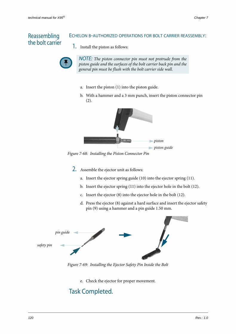
technical manual for X95® Chapter 7
Reassembling the bolt carrier
ECHELON B-AUTHORIZED OPERATIONS FOR BOLT CARRIER REASSEMBLY:
1. Install the piston as follows:
a. Insert the piston (1) into the piston guide.
b. With a hammer and a 3 mm punch, insert the piston connector pin (2).
Figure 7-68: Installing the Piston Connector Pin
2. Assemble the ejector unit as follows:
a. Insert the ejector spring guide (10) into the ejector spring (11).
b. Insert the ejector spring (11) into the ejector hole in the bolt (12).
c. Insert the ejector (8) into the ejector hole in the bolt (12).
d. Press the ejector (8) against a hard surface and insert the ejector safety pin (9) using a hammer and a pin guide 1.50 mm.
Figure 7-69: Installing the Ejector Safety Pin Inside the Bolt
e. Check the ejector for proper movement.
Task Completed.
NOTE: The piston connector pin must not protrude from the piston guide and the surfaces of the bolt carrier back pin and the general pin must be flush with the bolt carrier side wall.
piston
piston guide
safety pin
pin guide
120 Rev.: 1.0

Field Disassembly Procedures
ECHELON A-AUTHORIZED OPERATIONS FOR BOLT CARRIER REASSEMBLY:
1. Assemble the extractor unit as follows:
a. Insert the extractor spring (16) into its slot on the bolt (12), with the bigger diameter interfacing the bolt surface.
b. Insert the extractor (15) into its place and align the holes.
c. Press the extractor (15) and insert the extractor pin (14).
2. With a hammer and a 3 mm punch, insert the bolt carrier back pin (7) into its place on the back RH side of the bolt carrier for a RH configura-tion (or from LH side for a LH configuration).
Figure 7-70: Installing the Bolt Carrier Back Pin
3. With a hammer and a 3 mm punch, insert the general pin (5) into its place on the front—form the RH side of the bolt carrier for a RH configuration (or from the LH side for a LH configuration).
Figure 7-71: Installing the General Pin
4. Verify that the bolt carrier group is assembled properly and the piston (1) is not locked in place (free side movements).
P/N: 0070572002AEN 121

technical manual for X95® Chapter 7
5. Install the bolt unit in its place in the bolt carrier as follows:
a. Install the bolt (12) in its place in the bolt carrier.
b. Insert the firing pin (13) into the bolt (12) and turn 180°.
c. Install the bolt guide pin (6).
6. Assemble the bolt carrier guide bar unit as follows:
a. Push the bolt carrier guide rod (3) into the buffer (4).
b. With a hammer, knock on the buffer (4) to secure it in place.
7. Install the bolt carrier guide rod (3) in its place in the bolt carrier.
Task Completed.
NOTE: While inserting the bolt guide pin, the bolt and the fir-ing pin grooves must be facing up and the bolt guide pin must enter its place in the bolt carrier sink.
122 Rev.: 1.0

Field Disassembly Procedures
+
+
+
+
+
7.2.15 Gas Cylinder Disassembly at Echelons A & B
Figure 7-72: Gas Cylinder Parts
EQUIPMENT & TOOLS:
• none
• punch, 1.50 mm x2
• pliers, sharp nose
models with detachable optical sight:
models with integral reflex sight:
# PART NUMBER PART DESCRIPTION
1 007990212 cylinder, gas (models with detachable optical sight)
2 007040212 cylinder, gas (models with integral reflex sight)
3 0070475213 retaining ring (models with integral reflex sight)
4 007040203 pivot, rear sight (models with integral reflex sight)
5 007040202 spring, rear sight (models with integral reflex sight)
6 007040221 sight, rear (models with integral reflex sight)
applicable to models:
X95
X95 CPRF
X95 MSW
X95 SMG
X95S SMG
1
4 3
5
6
2
P/N: 0070572002AEN 123

technical manual for X95® Chapter 7
Disassembling the gas cylinder
To disassemble the gas cylinder, perform the steps as follows:
ECHELON A-AUTHORIZED OPERATIONS FOR GAS CYLINDER DISASSEMBLY:
1. Push the gas cylinder (1/2) forward until a third of it comes out of its track; apply additional force in the same direction until the gas cylinder comes out completely.
Figure 7-73: Removing the Gas Cylinder
Task Completed.
ECHELON B-AUTHORIZED OPERATIONS FOR GAS CYLINDER DISASSEMBLY:
1. With two punches 1.5 mm, open the retaining ring (3) by applying force in both directions.
2. With a 1.5 mm punch, push out the rear sight pivot (4) and remove the rear sight (6).
models with integral reflex sight
models with detachable optical sight
NOTE: The following steps are applicable only to models with integral reflex sight.
124 Rev.: 1.0

Field Disassembly Procedures
3. With sharp nose pliers, pull out the rear sight spring (5).
Figure 7-74: Disassembling the Gas Cylinder
Task Completed.
Reassembling the gas cylinder
To reassemble the gas cylinder, perform the steps as follows:
ECHELON B-AUTHORIZED OPERATIONS FOR GAS CYLINDER REASSEMBLY:
1. With sharp nose pliers, install the rear sight spring (5) inside the rear sight (6).
2. Assemble the rear sight unit and the rear sight pivot (4) on the gas cylin-der (2).
3. With a punch, close the retaining ring (3) in place.
Figure 7-75: Closing the Retaining Ring
Task Completed.
retaining ring rear sight pivot
NOTE: Steps 1 through 3 are applicable only to models with integral reflex sight.
P/N: 0070572002AEN 125

technical manual for X95® Chapter 7
ECHELON A-AUTHORIZED OPERATIONS FOR GAS CYLINDER REASSEMBLY:
Place the gas cylinder (1) in front of the receiver rails; align the rails of the gas cylinder with the slots in the insert and push the gas cylinder into place.
Figure 7-76: Installing the Gas Cylinder
Task Completed.
models with integral reflex sight
models with detachable optical sight
126 Rev.: 1.0

Field Disassembly Procedures
+
+
+
+
+
7.2.16 Safety Group Disassembly at Echelon B
Figure 7-77: Safety Group
EQUIPMENT & TOOLS:
• punch, 1.50 mm
• punch, 2.00 mm
• screwdriver, flat
• hammer, metal
# PART NUMBER PART DESCRIPTION
1 007051015 lever, fire selector
2 007041016 positioning spring, safety
3 007041017 cover, safety pivot
4 007041054 pin, safety plunger
5 007051051 safety
6 007041052 plunger, LH, safety
7 007041055 spring, safety plunger
8 007041053 plunger, RH, safety
applicable to models:
X95
X95 CPRF
X95 MSW
X95 SMG
X95S SMG
1 2
3
4
5
67
8
P/N: 0070572002AEN 127
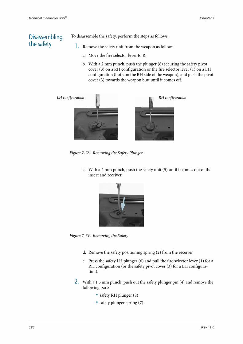
technical manual for X95® Chapter 7
Disassembling the safety
To disassemble the safety, perform the steps as follows:
1. Remove the safety unit from the weapon as follows:
a. Move the fire selector lever to R.
b. With a 2 mm punch, push the plunger (8) securing the safety pivot cover (3) on a RH configuration or the fire selector lever (1) on a LH configuration (both on the RH side of the weapon), and push the pivot cover (3) towards the weapon butt until it comes off.
Figure 7-78: Removing the Safety Plunger
c. With a 2 mm punch, push the safety unit (5) until it comes out of the insert and receiver.
Figure 7-79: Removing the Safety
d. Remove the safety positioning spring (2) from the receiver.
e. Press the safety LH plunger (6) and pull the fire selector lever (1) for a RH configuration (or the safety pivot cover (3) for a LH configura-tion).
2. With a 1.5 mm punch, push out the safety plunger pin (4) and remove the following parts:
• safety RH plunger (8)• safety plunger spring (7)
LH configuration RH configuration
128 Rev.: 1.0

Field Disassembly Procedures
• safety LH plunger (6)
Figure 7-80: Disassembling the Safety
Task Completed.
Reassembling the safety
To reassemble the safety, perform the steps as follows:
1. Assemble the safety as follows:
a. Insert the small diameter side of the safety LH plunger (6) into place.
b. Insert the safety plunger spring (7) into place.
c. Insert the safety RH plunger (8) into place so that the safety plunger slot is against the safety pin hole.
d. With a hammer, insert the safety plunger pin (4).
e. Assemble the safety cover (3).
2. Install the safety unit in its place in the receiver as follows:
a. Install the safety positioning spring (2) in the receiver with the embossment pointing up.
Figure 7-81: Installing the Safety Positioning Spring
b. Insert the safety unit (5) into its hole from the LH side of the receiver.
P/N: 0070572002AEN 129

technical manual for X95® Chapter 7
c. With a 2 mm punch, lightly push the safety (5) against the safety posi-tioning spring (2) and push it into the safety hole on the RH side of the receiver.
Figure 7-82: Installing the Safety Inside the Receiver
d. Assemble the safety pivot cover (3) for RH configuration (or the fire selector lever (1) for LH configuration) by pressing the securing plunger (8) and pushing the parts to the opposite direction.
3. Check the safety for proper movement and smooth clicks.
Task Completed.
130 Rev.: 1.0

Field Disassembly Procedures
+
+
+
+
+
7.2.17 Sear Mechanism Disassembly at Echelon B
Figure 7-83: Sear Mechanism Parts
EQUIPMENT & TOOLS:
• pin guide, 2.00 mm
• punch, 1.500 mm
• punch, 4.00 mm
• hammer, metal
• screwdriver, flat
• sharp nose pliers
applicable to models:
X95
X95 CPRF
X95 MSW
X95 SMG
X95S SMG
1
2
3
4
5
6
78
9
10
1112
13
14
1516 17
P/N: 0070572002AEN 131

technical manual for X95® Chapter 7
# PART NUMBER PART DESCRIPTION
1 007044009 pivot, hammer
2 007044001 hammer
3 007044017 securing pin, hammer
4 007044012 spring, hammer
5 007044013 spring, sear activator
6 007044003 sear
7 007044005 sear, automatic
8 007044008 bushing, sear pivot
9 007044016 ring spring, internal
10 007044004 spring, automatic sear
11 007044007 plunger, sear
12 007044014 spring, sear plunger
13 007044006 activator, sear
14 007044019 secondary spring, sear activator
15 007044002 housing, mechanism
16 007044018 pin, sear activator spring
17 007044015 pivot, sear
132 Rev.: 1.0

Field Disassembly Procedures
Disassembling the sear mechanism
To disassemble the mechanism, perform the steps as follows:
1. Disassemble the hammer unit as follows:
a. Push down the automatic sear (7) and release the hammer (2) from the automatic sear (7).
Figure 7-84: Releasing the Hammer from the Automatic Sear
b. With a 4 mm punch, pull forward the sear activator (13) to release the hammer (2) from the sear (6).
Figure 7-85: Releasing the Hammer from the Sear
P/N: 0070572002AEN 133

technical manual for X95® Chapter 7
c. With a 2 mm punch, push out the hammer securing pin (3).
Figure 7-86: Removing the Hammer Securing Pin
d. With a 4 mm punch, push out the hammer pivot (1) and remove the hammer (2) and hammer spring (4); separate the hammer spring (4) from the hammer (2).
Figure 7-87: Removing the Hammer Pivot
2. Disassemble the sear activator unit as follows:
a. With a 2 mm punch, release the sear activator secondary spring (14) from the leg of the sear activator (13).
Figure 7-88: Releasing the Sear Activator Secondary Spring
134 Rev.: 1.0

Field Disassembly Procedures
b. With a hammer and a 4 mm punch, remove the sear pivot (17) and take the sear activator unit (13) out of the mechanism housing (15).
Figure 7-89: Removing the Sear Activator Unit from the Mechanism Housing
c. Take off the sear activator spring (5) from the LH side of the sear acti-vator (13), and the automatic sear spring (10) from the RH side of the sear activator (13).
Figure 7-90: Disassembling the Sear Activator Unit—Step 1
d. Pull the sear pivot bushing (8) out of the sear activator (13), and sepa-rate the sear (6), automatic sear (7), sear plunger unit (11), and inter-nal ring spring (9).
Figure 7-91: Disassembling the Sear Activator Unit—Step 2
P/N: 0070572002AEN 135

technical manual for X95® Chapter 7
e. With a 2 mm punch, remove the sear plunger spring (12) from the sear plunger (11).
Figure 7-92: Disassembling the Sear Activator Unit—Step 3
f. With a 4 mm punch, remove the sear activator spring pin (16) and take the sear activator secondary spring (14) out of the mechanism housing (15).
Figure 7-93: Disassembling the Sear Activator Unit—Step 4
Task Completed.
Reassembling the sear mechanism
To reassemble the sear mechanism, perform the steps as follows:
1. Align the activator spring ring (9) with the hole on the internal right wall of the mechanism housing (15), and insert the sear activator spring pin (16).
2. Install the internal ring spring (9) on the sear pivot bushing (8).
3. Install the hammer spring (4) on the hammer (2).
Figure 7-94: Hammer Spring Installed
4. Direct the LH leg of the sear activator (13) upwards and insert the sear (6) into place.
5. Push the sear pivot bushing (8) from the RH side until it aligns with the surface of the automatic sear (7).
136 Rev.: 1.0

Field Disassembly Procedures
Figure 7-95: Installing the Sear Plunger Spring
6. Insert the sear plunger (11) into the LH hole of the sear activator (13), with the spring side entering first.
7. Insert the automatic sear (7) and push the sear pivot bushing (8) to its final position.
8. Install the automatic sear spring (10) from the RH side of the sear activa-tor (13) so that the short leg supports the automatic sear (7).
Figure 7-96: Assembling the Sear Activator Unit
9. Insert the sear activator unit (13) into the mechanism housing (15) so that the sear activator spring (5) is above the sear pivot bushing (8) on the LH side.
10. Press the sear activator (13) and align the holes.
11. With a metal hammer, insert the sear pivot (17).
Figure 7-97: Installing the Sear Pivot
NOTE: Make sure you install the sear plunger spring so that the closed link of the spring rests on the plunger head.
sear plunger headclosed link
P/N: 0070572002AEN 137

technical manual for X95® Chapter 7
12. Bend the arm of the automatic sear spring (10) and place it under the leg of the automatic sear (7).
13. Install the hammer unit (2) so that the arms of the hammer spring (4) rest on the mechanism housing wall and their edges point inside the mecha-nism housing (15).
Figure 7-98: Installing the Hammer
14. Push the hammer unit (2) down until the holes are aligned and insert the hammer pivot (1) to its final position.
15. With a flat screwdriver, locate the hammer pivot hole and screw the ham-mer pivot (1) into place.
Figure 7-99: Installing the Hammer Pivot
138 Rev.: 1.0

Field Disassembly Procedures
16. With a pin guide 2 mm, insert the hammer securing pin (3) so that it goes under the wall surface on both sides.
Figure 7-100:Installing the Hammer Securing Pin
17. With sharp nose pliers and a hammer, engage the sear activator spring pin (16) in the loop of the sear activator secondary spring (14).
18. Check the sear mechanism for proper operation.
Task Completed.
P/N: 0070572002AEN 139

technical manual for X95® Chapter 7
140 Rev.: 1.0

CHAPTER 8
SPECIAL TOOLS &
GAUGESThis chapter describes the special maintenance tools and inspection gauges for the X95®, hereafter referred to as "SM&TEs" ("Special Maintenance & Testing Equip-ment"). The following paragraphs contain recommendations for ST&MEs periodic maintenance and procedures for gauge inspection.
P/N: 0070572002AEN 141

technical manual for X95® Chapter 8
8.1 Nomenclature of SM&TEsThe following tables contain the nomenclature of the SM&TEs for the X95®.
Table 8.1: Special Maintenance Tools
# PART NUMBER PART DESCRIPTION
1 0070475101 wrench, barrel
2 0070475111 wrench, zeroing
Table 8.2: Special Testing Equipment for Assault Rifle Models
# PART NUMBER PART DESCRIPTION
1 00050519001 gauge, headspace, GO 37.984
2 00050519002 gauge, head space, NO GO 38.300
3 00050519004 gauge, barrel straightness
4 004295211 gauge, barrel wear
5 00704310000061 gauge, firing pin protrusion
142 Rev.: 1.0

Nomenclature of SM&TEs
Table 8.3: Special Testing Equipment for Submachine Gun Models
# PART NUMBER PART DESCRIPTION
1 0071500000061 gauge, headspace
2 050517031 gauge, barrel straightness
3 050517020 gauge, barrel wear
4 001970891 gauge, silencer centrality
P/N: 0070572002AEN 143

technical manual for X95® Chapter 8
8.2 Maintenance of SM&TEsAlthough the SM&TEs for the X95® require minimum maintenance, they wear out naturally throughout the life-cycle. Performing the following procedures regularly helps to keep the SM&TEs in good condition and ensure their longev-ity.
Periodic inspection
Based on expected wear, SM&TE must undergo periodic checks for dimensions, integrity, and proper operation. Such checks are carried out according to ISO 9001 QA Standard.
Calibration (STEs only)
STEs are subject to periodic calibration in accordance with the MIL-STD-45662 requirements.
144 Rev.: 1.0
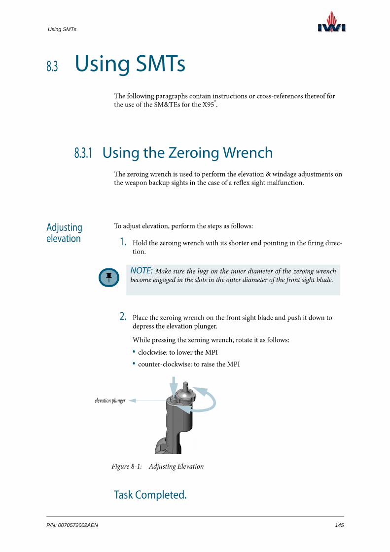
Using SMTs
8.3 Using SMTsThe following paragraphs contain instructions or cross-references thereof for the use of the SM&TEs for the X95®.
8.3.1 Using the Zeroing WrenchThe zeroing wrench is used to perform the elevation & windage adjustments on the weapon backup sights in the case of a reflex sight malfunction.
Adjusting elevation
To adjust elevation, perform the steps as follows:
1. Hold the zeroing wrench with its shorter end pointing in the firing direc-tion.
2. Place the zeroing wrench on the front sight blade and push it down to depress the elevation plunger.
While pressing the zeroing wrench, rotate it as follows:
• clockwise: to lower the MPI• counter-clockwise: to raise the MPI
Figure 8-1: Adjusting Elevation
Task Completed.
NOTE: Make sure the lugs on the inner diameter of the zeroing wrench become engaged in the slots in the outer diameter of the front sight blade.
elevation plunger
P/N: 0070572002AEN 145

technical manual for X95® Chapter 8
Adjusting windage
To adjust windage, perform the steps as follows:
1. Insert the tip of the longer part of the zeroing wrench into the slot on the head of the windage screw.
2. Rotate the zeroing wrench as follows:
• clockwise: to shift the MPI left • counter-clockwise: to shift the MPI right
Figure 8-2: Adjusting Windage
Task Completed.
8.3.2 Using the Barrel WrenchFor information on how to use the barrel wrench, Refer to the Barrel Group Dis-assembly at Echelon A procedure on page 89.
windage screw
146 Rev.: 1.0

Using STEs— Gauge Inspection
8.4 Using STEs— Gauge Inspection
The following paragraphs explain how perform gauge inspections on the X95®.
Follow these rules every time you perform a gauge inspection:
• Prior to each gauge inspection, carry out safety inspection.
• Prior to each gauge inspection, clean the weapon thoroughly.
• Do not apply force using the gauges.
P/N: 0070572002AEN 147

technical manual for X95® Chapter 8
8.4.1 Headspace InspectionThe headspace inspection is used to ensure that the chamber-bolt dimensions (in assault rifle models) or the gap between the front of the breech block and the barrel base (in submachine gun models) match the bullet cartridge dimension.
The GO gauge/blade provides the essential dimension for the cartridge seat in the chamber, while the NO GO gauge/blade ensures that no cartridge breach happens because the chamber does not support the cartridge.
To perform the headspace inspection, follow these steps:
EQUIPMENT & TOOLS:
• gauge, headspace, GO (assault rifle models)
• gauge, headspace, NO GO (assault rifle models)
• gauge, headspace (submachine gun models)
Checking headspace in assault rifle models:
1. Remove the recoiling system; thoroughly clean the barrel, chamber, and bolt surface, and reinstall the recoiling system.
2. Cock the recoiling system and catch it on the last round catch.
3. Insert the gauge into the chamber.
4. Release the last round catch and check:
• Minimum head space—when the GO gauge is inside, the bolt should lock as if a regular bullet is inserted.
• Maximum head space—when the NO GO gauge is inside, the bolt should not lock.
Figure 8-3: Checking Headspace in Assault Rifle
Models
Task Completed.
GO gauge insidethe chamber
NO GO gauge insidethe chamber
148 Rev.: 1.0
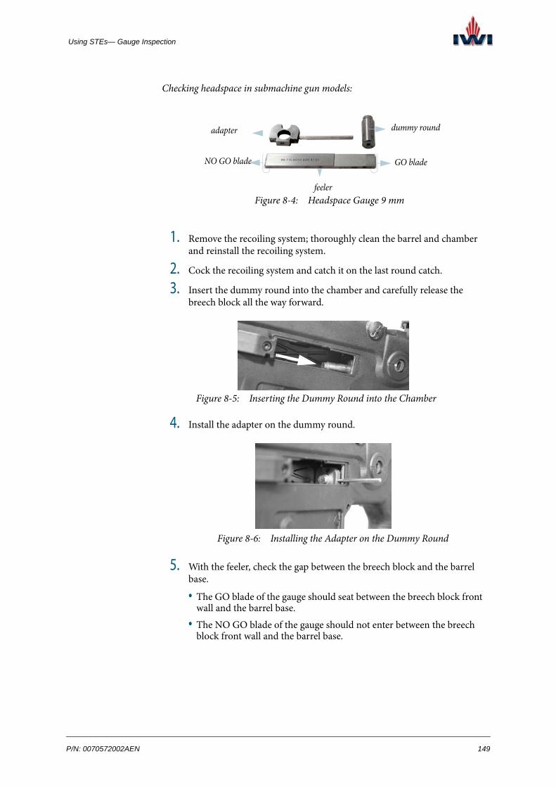
Using STEs— Gauge Inspection
Checking headspace in submachine gun models:
Figure 8-4: Headspace Gauge 9 mm
1. Remove the recoiling system; thoroughly clean the barrel and chamber and reinstall the recoiling system.
2. Cock the recoiling system and catch it on the last round catch.
3. Insert the dummy round into the chamber and carefully release the breech block all the way forward.
4. Install the adapter on the dummy round.
5. With the feeler, check the gap between the breech block and the barrel base.
• The GO blade of the gauge should seat between the breech block front wall and the barrel base.
• The NO GO blade of the gauge should not enter between the breech block front wall and the barrel base.
dummy round adapter
feeler
GO bladeNO GO blade
Figure 8-5: Inserting the Dummy Round into the Chamber
Figure 8-6: Installing the Adapter on the Dummy Round
P/N: 0070572002AEN 149

technical manual for X95® Chapter 8
Task Completed.Figure 8-7: Checking Headspace in Submachine Gun Models
GO blade seats betweenthe breech block and barrel
NO GO blade too wide to enter between the breech block and barrel
150 Rev.: 1.0

Using STEs— Gauge Inspection
8.4.2 Barrel Straightness Inspection
To perform the barrel straightness inspection, follow these steps:
1. Remove the recoiling system from the weapon. (Refer to the Primary dis-assembly procedure on page 61.)
2. Clean the barrel bore using cleaning rod.
3. Hold the tip of the barrel straightness gauge with sharp nose pliers.
4. Slowly insert the barrel straightness gauge from the muzzle end —the gauge should pass through the barrel on its own.
Figure 8-8: Barrel Straightness Inspection
Task Completed.
EQUIPMENT & TOOLS:
• barrel straightness gauge
CAUTION! To protect the gauge (prevent the gauge from falling down), place a finger at the bottom of the barrel while car-rying out the inspection.
P/N: 0070572002AEN 151

technical manual for X95® Chapter 8
8.4.3 Barrel Wear Inspection
To perform the barrel wear inspection, insert the gauge from the chamber side into the barrel.
The gauge has two marks - red and green:
• If the gauge enters only up to the green mark - the barrel wear status is in order.
• If the gauge enters up to the red mark - the barrel is worn.
Figure 8-9: Barrel Wear Inspection
Task Completed.
EQUIPMENT & TOOLS:
• barrel wear gauge
Checking barrel wear in assault rifle models:
Checking barrel wear in submachine gun models:
152 Rev.: 1.0

Using STEs— Gauge Inspection
8.4.4 Firing Pin Protrusion Inspection in Assault Rifle Models
To perform the firing pin protrusion inspection, follow these steps:
1. Hold the bolt perpendicularly so that the firing pin is pressed against a surface and its tip protrudes.
2. Press the gauge end that is marked with GO against the bolt surface and slide its n-shaped end over the firing pin tip.
The gauge should pass over without touching the firing pin tip.
3. Flip the gauge vertically, press the gauge end that is marked with NO GO against the bolt surface and slide its n-shaped end over the firing pin tip.
The gauge must be stopped by the firing pin tip.
Figure 8-10: Firing Pin Protrusion Inspection
Task Completed.
NOTE: The firing pin protrusion inspection is applicable to assault rifle models only.
EQUIPMENT & TOOLS:
• firing pin protrusion gauge
P/N: 0070572002AEN 153
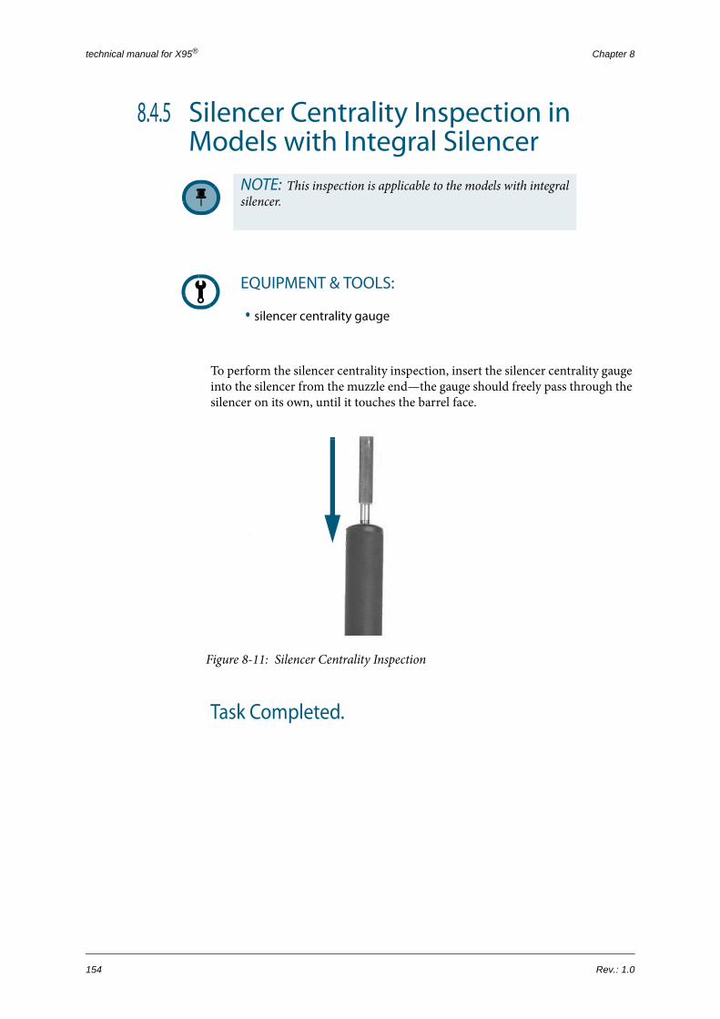
technical manual for X95® Chapter 8
8.4.5 Silencer Centrality Inspection in Models with Integral Silencer
To perform the silencer centrality inspection, insert the silencer centrality gauge into the silencer from the muzzle end—the gauge should freely pass through the silencer on its own, until it touches the barrel face.
Figure 8-11: Silencer Centrality Inspection
Task Completed.
NOTE: This inspection is applicable to the models with integral silencer.
EQUIPMENT & TOOLS:
• silencer centrality gauge
154 Rev.: 1.0

CHAPTER 9
WEAPON CONVERSION
This chapter details the following weapon conversion procedures:
• conversion between RH and LH shooter
• conversion between 5.56 mm and 9 mm calibers
P/N: 0070572002AEN 155

technical manual for X95® Chapter 9
9.1 RH-LH Shooter ConversionTo ensure operation by the LH shooter, the following parts should be transferred to the weapon RH side:
• cocking handle
• fire selector lever
The deflector, on the contrary, must be moved to the weapon LH side to avoid the operator’s injury from the spent case during ejection.
The following figure illustrates the conversion process:
Figure 9-1: Conversion to LH Shooter
156 Rev.: 1.0

RH-LH Shooter Conversion
To convert the weapon from RH to LH shooter, perform the steps as follows:
1. Perform the primary disassembly. (p. 61)
2. For assault rifle models only: Shift the cocking handle to the right as fol-lows:
a. Remove the fore grip group. (p. 80)
b. Remove the cocking handle bar group. (p. 87)
c. Remove the barrel. (p. 90)
d. Place the front shield on the gas cylinder so that the small slot points in the opposite direction.
Figure 9-2: Converting the Front Shield for the LH Shooter
e. Install the barrel. (p. 91)
f. Install the cocking handle bar group in its rail so that the cocking han-dle is on the RH side of the weapon. (p. 88)
g. Install the fore grip group. (p. 85)
3. Shift the fire selector lever to the right as follows:
a. Remove the safety pivot cover and fire selector lever from the receiver. (p. 128)
b. Install the fire selector lever on the RH side.
c. Install the safety pivot cover on the LH side; secure with the plunger.
4. Shift the middle swivel to the right as follows:
a. Remove the middle swivel from the weapon. (p. 93)
b. Install the middle swivel on the weapon RH side. (p. 94)
5. Switch sides between the ejection port cover and the deflector as follows:
a. Remove the ejection port cover and the ejection port cover base from the weapon LH side (p. 107) and reinstall them on the RH side (p. 109).
b. Remove the deflector (in assault rifle models, remove the deflector frame as well) from the weapon RH side (p. 106) and reinstall them on the LH side (p. 109).
P/N: 0070572002AEN 157

technical manual for X95® Chapter 9
6. Convert the bolt carrier group to the LH configuration as follows:
a. Perform the secondary disassembly. (p. 62)
b. Remove the general pin and the bolt carrier back pin from the bolt car-rier RH side (p. 117) and reinstall them on the bolt carrier LH side (p. 121).
c. Insert the LH bolt and the firing pin into the bolt carrier.
d. Install the bolt guide pin in its place in the bolt carrier.
e. Install the bolt carrier group inside the receiver and close the butt.
f. Press the butt locking pin and lock the butt.
Task Completed.
158 Rev.: 1.0

Caliber Conversion
9.2 Caliber ConversionThe interchangeable mechanism of the X95® allows to support two different cali-bers within one weapon:
• 5.56 mm (assault rifle models)
• 9 mm (submachine gun models)
Special equipment is required to convert the X95® between calibers.
Figure 9-3: Conversion Kits for 9 mm and for 9 mm Silenced
# PART DESCRIPTION
1 barrel assembly, 9 mm
2 barrel assembly 9 mm silenced
3 breech block group, 9 mm
4 adapter, magazine 9 mm
5 magazine, 9 mm
1 233
4 455
conversion kit for 9 mm conversion kit for 9 mm silenced
P/N: 0070572002AEN 159

technical manual for X95® Chapter 9
Figure 9-4: Conversion Kit for 5.56 mm
5.56 mm - 9 mm conversion
To convert an assault rifle 5.56 mm to a submachine gun 9 mm, perform the steps as follows:
1. Perform the primary disassembly (p. 61).
2. Remove the flash suppressor and the front swivel (p. 73).
3. Remove the fore grip group (p. 80).
4. Extract the cocking handle bar group from the weapon.
5. Remove the barrel 5.56 mm and install the barrel 9 mm. Refer to the Bar-rel Group Disassembly at Echelon A procedure on page 89.
6. Install the cocking handle bar inside the weapon.
7. Install the fore grip group (p. 85).
8. Disassemble the deflector group (p. 106), put the deflector frame aside and reinstall the deflector on the extraction port shield.
9. Install one of the following:
• the flash suppressor (p. 74)
# PART DESCRIPTION
1 barrel assembly, 5.56 mm
2 bolt carrier group, 5.56 mm
3 magazine, 5.56 mm
1
2
3
160 Rev.: 1.0

Caliber Conversion
• silencerTo install the silencer, screw it to the barrel and conduct the silencer cen-trality inspection.
10. Install the magazine adapter.
a. Hold the magazine catch button down and insert the magazine adapter unit into the receiver as deeply as possible.
b. With a 4 mm punch and a hammer, insert the magazine adapter attach-ment pins.
11. Convert the recoiling system as follows:
a. Install the breech block group into the receiver and close the butt.
b. Press the butt locking pin and lock the butt.
Task Completed.
P/N: 0070572002AEN 161

technical manual for X95® Chapter 9
9 mm - 5.56 mm conversion
To convert a submachine gun 9 mm to an assault rifle 5.56 mm, perform the steps as follows:
1. Remove the silencer (p. 75) /flash suppressor (p. 73).
2. Remove the fore grip group. (p. 80)
3. Extract the cocking handle bar from the weapon.
4. Remove the barrel 9 mm and install the barrel 5.56 mm. Refer to the Bar-rel Group Disassembly at Echelon A procedure on page 89.
5. Install the cocking handle bar.
6. Install the fore grip group. (p. 85)
7. Disassemble the deflector (p. 106) and reinstall it together with the deflec-tor frame.
8. Install the flash suppressor (p. 74).
9. Remove the magazine adapter. (p. 111)
10. Convert the recoiling system as follows:
a. Perform the primary disassembly. (p. 61)
b. Install the bolt carrier group into the receiver and close the butt.
c. Press the butt locking pin and lock the butt.
Task Completed.
162 Rev.: 1.0

CHAPTER 10
AIMING SYSTEMThis chapter details the installation/removal procedures for the primary sight of the X95®.
P/N: 0070572002AEN 163

technical manual for X95® Chapter 10
10.1 GeneralBased on the customer’s requirements, the X95® comes equipped with an integral reflex sight attached directly to the barrel or a detachable reflex sight mounted on the top receiver Picatinny adapter.
The following paragraphs detail the procedures for the removal/installation of various sights available for the X95®.
164 Rev.: 1.0

Removal/Installation of the MEPRO 21 Integral Reflex Sight
+
+
+
+
+
10.2 Removal/Installation of the MEPRO 21 Integral Reflex Sight1
Figure 10-1: Integral MEPRO 21 Reflex Sight
Removing the MEPRO 21 integral reflex sight
To remove the MEPRO 21 integral reflex sight, proceed as follows:
1 For more information on the MEPRO 21 reflex sight, refer to the OEM Operation and Maintenance Man-ual.
EQUIPMENT & TOOLS:
• closed Hex wrench 9/32" or 7.00 mm
• Loctite 242 glue
applicable to models:
X95
X95 CPRF
X95 MSW
X95 SMG
X95S SMG
NOTE: You can remove the MEPRO 21 reflex sight only after the barrel has been disassembled from the weapon. Refer to the Barrel Group Disassembly at Echelon A procedure on page 89.
P/N: 0070572002AEN 165
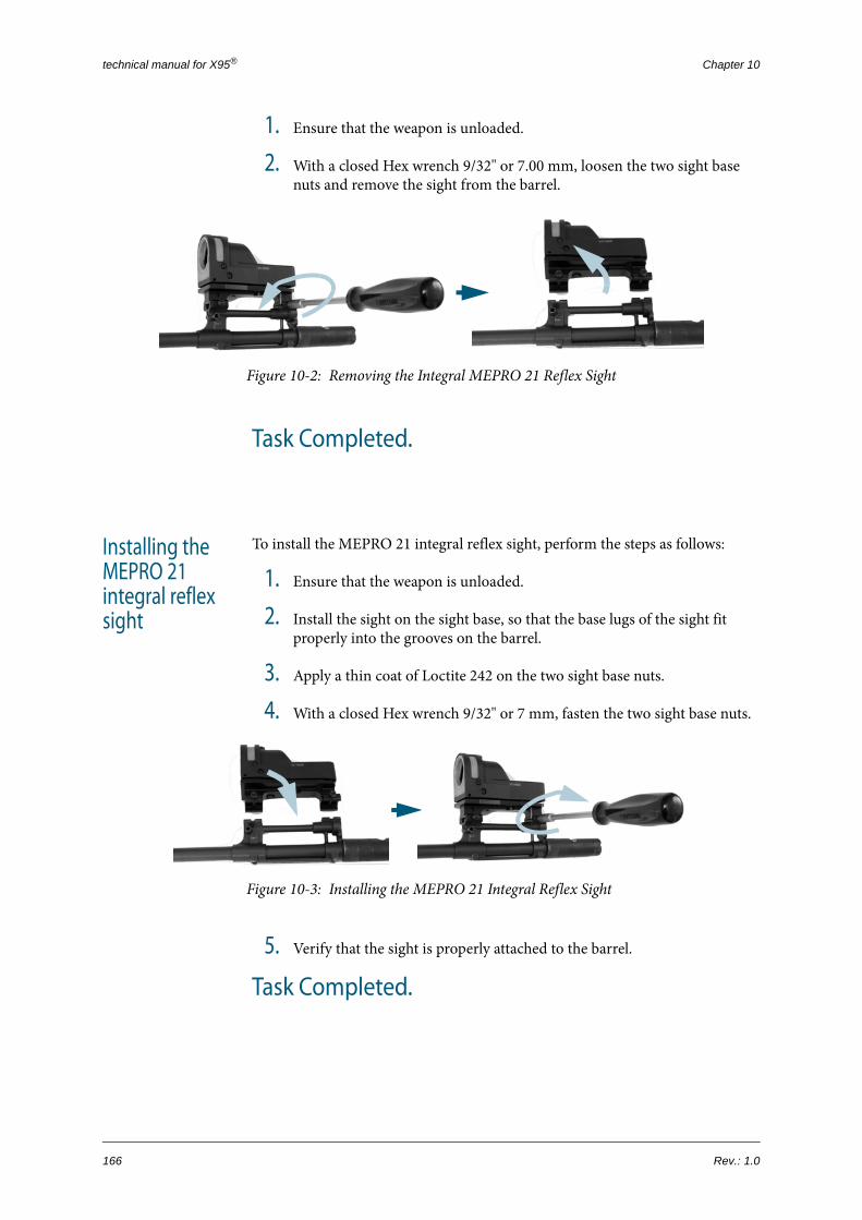
technical manual for X95® Chapter 10
1. Ensure that the weapon is unloaded.
2. With a closed Hex wrench 9/32" or 7.00 mm, loosen the two sight base nuts and remove the sight from the barrel.
Figure 10-2: Removing the Integral MEPRO 21 Reflex Sight
Task Completed.
Installing the MEPRO 21 integral reflex sight
To install the MEPRO 21 integral reflex sight, perform the steps as follows:
1. Ensure that the weapon is unloaded.
2. Install the sight on the sight base, so that the base lugs of the sight fit properly into the grooves on the barrel.
3. Apply a thin coat of Loctite 242 on the two sight base nuts.
4. With a closed Hex wrench 9/32" or 7 mm, fasten the two sight base nuts.
Figure 10-3: Installing the MEPRO 21 Integral Reflex Sight
5. Verify that the sight is properly attached to the barrel.
Task Completed.
166 Rev.: 1.0

Disassembling/Reassembling the Top Receiver Picatinny Adapter
+
+
+
+
+
10.3 Disassembling/Reassem-bling the Top Receiver Pica-tinny Adapter
Figure 10-4: Top Receiver Picatinny Adapter Parts
NOTE: This procedure is applicable only to models with detachable optical sight.
EQUIPMENT & TOOLS:
• Allen wrench
• punch, any size x2
• flat screwdriver
applicable to models:
X95
X95 CPRF
X95 MSW
X95 SMG
X95S SMG
1
2
3
4
5
6
6
77
8
9
910
10
1111
1212
P/N: 0070572002AEN 167

technical manual for X95® Chapter 10
Disassembling the top receiver Picatinny adapter
To disassemble the top receiver Picatinny adapter as follows:
1. Raise the rear sight on the rail. With an Allen wrench, release the rail attachment screws and remove both screws and the lock washers.
Figure 10-5: Releasing the Rail Attachment Screws
2. With an Allen wrench, release the Picatinny adapter base attachment screws and remove the screws and the lock washer springs. Take off the
# PART NUMBER PART DESCRIPTION
1 0070475521 sight, rear
2 004261933N spring, backup sight
3 0070475213 retaining ring
4 0070475215 pivot
5 0070575515 spiral pin
6 0070475514 x2 attachment screw, Picatinny adapter base
7 007046005 x2 spring, lock washer
8 0070575511 adapter, Picatinny
9 007046002 x2 clamp, sight base
10 0070475512 x2 base, Picatinny adapter
11 0070475513 x2 attachment screw, rail
12 0070475516 x2 lock washer, toothed
168 Rev.: 1.0

Disassembling/Reassembling the Top Receiver Picatinny Adapter
sight base clamps, the Picatinny adapter unit, and the adapter bases from the sight base.
Figure 10-6: Releasing the Picatinny Adapter Base Attachment Screw
3. Disassemble the top receiver Picatinny adapter as follows:
a. With two punches, open up the retaining ring that secures the pivot.
Figure 10-7: Opening the Retaining Ring
b. Raise the rear sight no the rail. With a punch and a hammer, push out the pivot and remove the rear sight.
Figure 10-8: Removing the Rear Sight
P/N: 0070572002AEN 169

technical manual for X95® Chapter 10
c. With a punch and a hammer, push out the spiral pin and remove the rear sight spring.
Figure 10-9: Removing the Spiral Pin
Task Completed.
Reassembling the top receiver Picatinny adapter
To reassemble the top receiver Picatinny adapter, perform the steps as follows:
1. Install the rear sight spring in its place; with a punch and a hammer, secure the sight with the spiral pin.
2. Install the rear sight and secure it with a punch from the adapter RH side.
3. Insert the pivot from the rail LH side and push it all the way in using a hammer; take the punch out.
4. With a flat screwdriver, install the retaining ring.
5. Install both Picatinny adapter bases on the sight base.
6. Install the top receiver Picatinny adapter on its bases.
7. Position each of the sight base clamps so that its hole is aligned with the matching hole on the adapter base; insert the Picatinny adapter attach-ment screw and secure using an Allen wrench.
Task Completed.
170 Rev.: 1.0

Installation/Removal of the MEPRO 21 Detachable Reflex Sight
+
-
-
-
-
10.4 Installation/Removal of the MEPRO 21 Detachable Reflex Sight1
Figure 10-10:Detachable MEPRO 21 Reflex Sight
Installing the detachable MEPRO 21 reflex sight
To install the detachable MEPRO 21 reflex sight on the top receiver Picatinny adapter, perform the steps as follows:
1 For more information on the MEPRO 21 reflex sight, refer to the OEM Operation and Maintenance Man-ual.
EQUIPMENT & TOOLS:
• Allen wrench
applicable to models:
X95
X95 CPRF
X95 MSW
X95 SMG
X95S SMG
quick-release Picatinny adapter
P/N: 0070572002AEN 171

technical manual for X95® Chapter 10
1. Ensure that the weapon is unloaded.
2. Attach the quick-release adaptor to the sight base to as follows:
Figure 10-11:Detachable MEPRO 21 Reflex Sight: Quick-Release Adapter
a. Place both parts of the quick-release adaptor together.
b. Insert the alignment pin into place.
c. Insert the quick-release adaptor screws and tighten them with an Allen wrench.
3. Open the both quick-release adaptor levers and install the adaptor on the Picatinny rail on the weapon receiver, so that the round studs on the adaptor engage the grooves on the Picatinny rail.
4. Close the quick-release adaptor levers.
Task Completed.
NOTE: You can install the MOR 21 reflex sight only after the fore grip has been disassembled from the weapon. Refer to the Fore Grip Group Disassembly at Echelon A procedure on page 79.
quick-release adapter LH part
quick-release adapter RH partalignment pin
quick-release adapter screws
172 Rev.: 1.0

Installation/Removal of the MEPRO 21 Detachable Reflex Sight
Removing the detachable MEPRO 21 reflex sight
To remove the detachable MEPRO 21 reflex sight, perform the steps of the installation in reverse order.
Task Completed.
P/N: 0070572002AEN 173

technical manual for X95® Chapter 10
174 Rev.: 1.0

JERICHO®

ISRAEL WEAPON INDUSTRIES (IWI) LTD.
64 Bialik Blvd. P.O.Box 63 Ramat Hasharon 47100 ISRAEL
Tel: + 972 3 760 60 00 Fax: + 972 3 760 60 01 Email: [email protected]