Embed Size (px)
Citation preview
x86 and C refresher Lab
Background: The x86 is a very widely used microprocessor, it is in Windows and Macintosh personal computers. It is important to be familiar with Intel Architecture, IA. In this lab we will be come familiar with the Intel Architecture using debuggers, assemblers, un-assemblers, and hand assembly. These tools will allow us to enter programs, assemble, execute, debug, and modify programs. Tools and techniques develop in this lab will prepare for using microcontrollers in later labs. C programs in this lab are to refresh C programming knowledge and explore C programming used in microprocessors. Also, this x86 – C refresher Lab will be preparation for using the C programming language to program microcontrollers. Objectives:
To be come familiar with how microprocessors operate.
To be come familiar with programming microprocessors using machine language, assembly language, and C language.
To be come proficient in the use microprocessor debugging tools and techniques.
To be come familiar with assemblers and their use in programming microprocessors.
To understand how to hand assemble instructions for microprocessors.
To understand the program development cycle (program-test-debug-modify-test-debug-repeat until done).
To use tracing charts, break points, to verify and debug programs.
To develop a program from a flow chart.
To write documented code with flow chart and commented code.
EEE174 CpE185 Laboratory S Spring 2016
1
X86 Lab Part 1: Introduction to Debug and C refresher Intro to DEBUG: Debug Monitor, Machine Language, and Assembly Language, Machine Instructions: MOV, SUB, ADD, JGE, INT 20h, and Debug Commands: d, e, u, r, and t Introduction: In this section, you will begin familiarizing yourself with the laboratory equipment. You will load and run a program in the DEBUG environment. You will then describe in detail the nature of this program and write a laboratory report based on your findings. The procedure for this experiment is presented below.
1. Examine the Virtual Machine (link to file on Voyager to run on a computer outside of the lab: \\voyager\Lab\EEE-CPE\Lab_VMs). To get to DEBUG: Click on “Start”. On the pull down menu select “Programs”. On the next menu select “MS-DOS Prompt” or “Command Prompt”. You should get the DOS prompt line “C:\WINDOWS>”.
Type “DEBUG” on the DOS prompt line, and the Debug prompt “-“ should appear. Type in a “?” for a listing of the DEBUG commands you can enter.
2. Use the DEBUG “dump” command (“d”) to display the contents of the memory locations. Enter the following three commands noting their effect.
a). d 0100 b). d 0100 0110 c). d 0100 0200
Describe and discuss the features of the display, such as the number of data blocks per row displayed for each of the above commands, the number system used, number of bits/byte, and the addressing scheme.
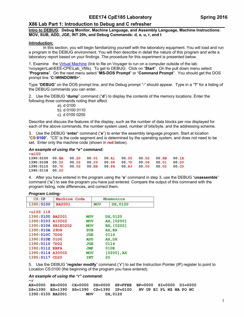
3. Use the DEBUG “enter” command (“e”) to enter the assembly language program. Start at location “CS:0100”. “CS” is the code segment and is determined by the operating system, and does not need to be set. Enter only the machine code (shown in red below).
An example of using the “e” command: -e100 1390:0100 00.BA 00.20 00.01 00.A1 00.00 00.02 00.8B 00.1E 1390:0108 00.02 00.02 00.29 00.D8 00.7D 00.06 00.01 00.D0 1390:0110 00.7D 00.02 00.EB 00.FA 00.A3 00.00 00.02 00.CD 1390:0118 00.20
4. After you have entered in the program using the “e” command in step 3, use the DEBUG “unassemble” command (“u”) to see the program you have just entered. Compare the output of this command with the program listing, note differences, and correct them.
Program Listing:
-u100 118
CS:IP Machine Code Mnemonics 1390:0100 BA2001 MOV DX,0120
1390:0100 BA2001 MOV DX,0120 1390:0103 A10002 MOV AX,[0200] 1390:0106 8B1E0202 MOV BX,[0202] 1390:010A 29D8 SUB AX,BX 1390:010C 7D06 JGE 0114 1390:010E 01D0 ADD AX,DX 1390:0110 7D02 JGE 0114 1390:0112 EBFA JMP 010E 1390:0114 A30002 MOV [0200],AX 1390:0117 CD20 INT 20
5. Use the DEBUG “register modify” command (“r”) to set the Instruction Pointer (IP) register to point to Location CS:0100 (the beginning of the program you have entered).
An example of using the “r” command: -r AX=0000 BX=0000 CX=0000 DX=0000 SP=FFEE BP=0000 SI=0000 DI=0000 DS=1390 ES=1390 SS=1390 CS=1390 IP=0100 NV UP EI PL NZ NA PO NC 1390:0100 BA2001 MOV DX,0120
EEE174 CpE185 Laboratory S Spring 2016
2
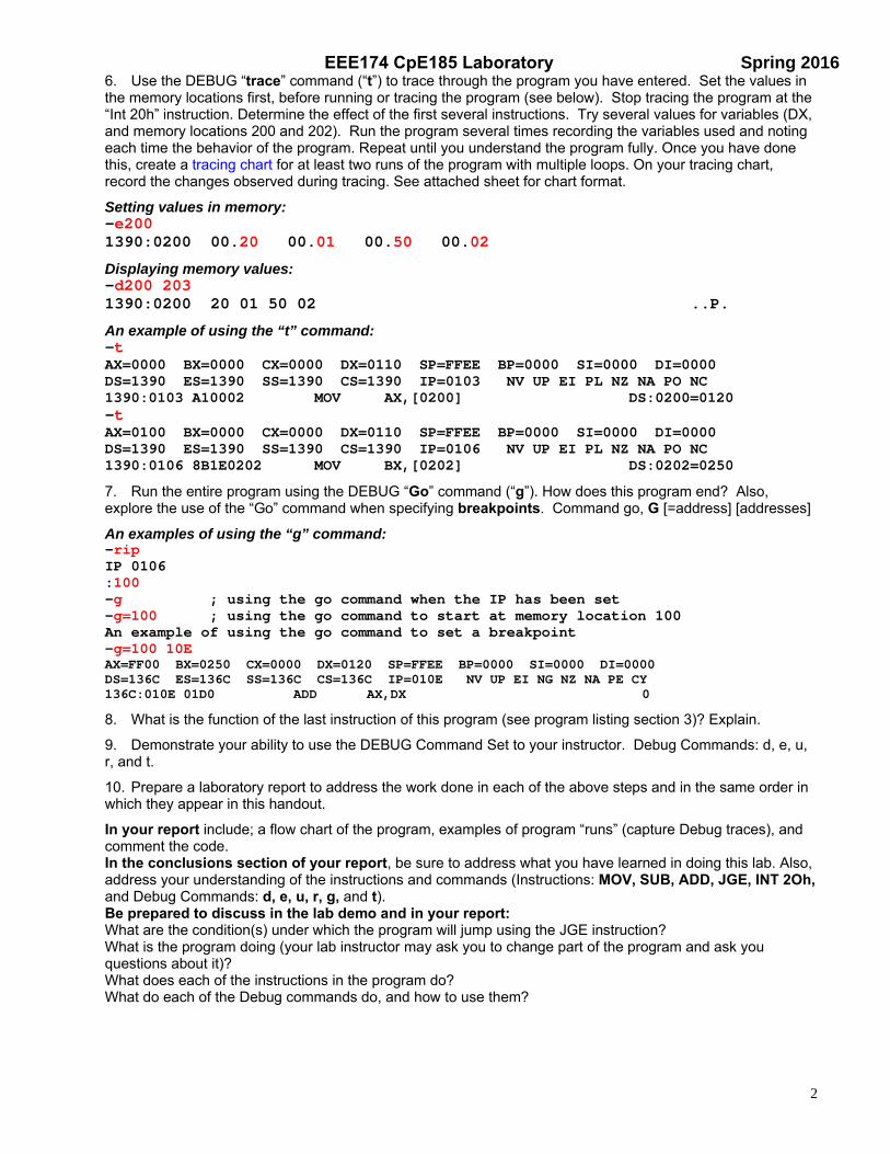
6. Use the DEBUG “trace” command (“t”) to trace through the program you have entered. Set the values in the memory locations first, before running or tracing the program (see below). Stop tracing the program at the “Int 20h” instruction. Determine the effect of the first several instructions. Try several values for variables (DX, and memory locations 200 and 202). Run the program several times recording the variables used and noting each time the behavior of the program. Repeat until you understand the program fully. Once you have done this, create a tracing chart for at least two runs of the program with multiple loops. On your tracing chart, record the changes observed during tracing. See attached sheet for chart format.
Setting values in memory: -e200 1390:0200 00.20 00.01 00.50 00.02
Displaying memory values: -d200 203 1390:0200 20 01 50 02 ..P.
An example of using the “t” command: -t AX=0000 BX=0000 CX=0000 DX=0110 SP=FFEE BP=0000 SI=0000 DI=0000 DS=1390 ES=1390 SS=1390 CS=1390 IP=0103 NV UP EI PL NZ NA PO NC 1390:0103 A10002 MOV AX,[0200] DS:0200=0120 -t AX=0100 BX=0000 CX=0000 DX=0110 SP=FFEE BP=0000 SI=0000 DI=0000 DS=1390 ES=1390 SS=1390 CS=1390 IP=0106 NV UP EI PL NZ NA PO NC 1390:0106 8B1E0202 MOV BX,[0202] DS:0202=0250
7. Run the entire program using the DEBUG “Go” command (“g”). How does this program end? Also, explore the use of the “Go” command when specifying breakpoints. Command go, G [=address] [addresses]
An examples of using the “g” command: -rip IP 0106 :100 -g ; using the go command when the IP has been set -g=100 ; using the go command to start at memory location 100 An example of using the go command to set a breakpoint -g=100 10E AX=FF00 BX=0250 CX=0000 DX=0120 SP=FFEE BP=0000 SI=0000 DI=0000 DS=136C ES=136C SS=136C CS=136C IP=010E NV UP EI NG NZ NA PE CY 136C:010E 01D0 ADD AX,DX 0
8. What is the function of the last instruction of this program (see program listing section 3)? Explain.
9. Demonstrate your ability to use the DEBUG Command Set to your instructor. Debug Commands: d, e, u, r, and t.
10. Prepare a laboratory report to address the work done in each of the above steps and in the same order in which they appear in this handout.
In your report include; a flow chart of the program, examples of program “runs” (capture Debug traces), and comment the code. In the conclusions section of your report, be sure to address what you have learned in doing this lab. Also, address your understanding of the instructions and commands (Instructions: MOV, SUB, ADD, JGE, INT 2Oh, and Debug Commands: d, e, u, r, g, and t). Be prepared to discuss in the lab demo and in your report: What are the condition(s) under which the program will jump using the JGE instruction? What is the program doing (your lab instructor may ask you to change part of the program and ask you questions about it)? What does each of the instructions in the program do? What do each of the Debug commands do, and how to use them?
EEE174 CpE185 Laboratory S Spring 2016
3
C Programming Refresher Write a “Hello” in C program Write a program to add two numbers in C. Write a program in C to perform the same function as the assembly language program used in Debug. Information on C: You can use any C compiler you like. Here are some links to information on C complier and tutorials: Tiny C Compiler: http://bellard.org/tcc/ Tiny C Compiler Reference Documentation: http://bellard.org/tcc/tcc-doc.html Programming in C: http://www.lysator.liu.se/c/ C Language Tutorial: http://www.physics.drexel.edu/students/courses/Comp_Phys/General/C_basics/ Demo Debug Introduction Lab: Be prepared by addressing the following items:
1. Flow Charts (see Flow Chart symbol section) give an example application of the assembly program. 2. Commented Code (comments to reflect on the flow chart and program application. 3. Fill out tracing chart (Excel version) for 2 runs with different values for the assembly program 4. PreLab: Hand Assembly Lab Pre Lab Flow Chart of program and hand assembly 5. Show your results, running the programs at demo including your C programs 6. Example program run
Be ready to answer questions on the program and Debug Break points?
7. Lab write up due after demo.
EEE174 CpE185 Laboratory S Spring 2016
4
X86 Lab Part 2: Hand Assembly and C programming Introduction: In this Hand-Assembly Lab, you will develop an 8-bit version of the program from Debug Introduction Lab, using byte-size data and registers (Debug Introduction Lab uses word size, 16 bit registers and data). Your program must meet the following specifications:
1. Use the JGE instruction only once (only one conditional jump). 2. Make no use of register (obtain from the link EEE174 CpE185 ) _____, neither its low nor high byte. 3. Use consecutive memory locations for data starting at the address _____; you will obtain from your
Lab Instructor. Note: Each person will have a unique register to not use and an address for data.
Also DO NOT use the Assembler in DEBUG. Refer to the hand-assembly examples. 4. After you have your program hand assembled and running, using the assemble command modify your
program to display your name and title of your program (see the “Welcome to EEE174” program). 5. Modify your program to keep track of how many times the overdraft (or bail out) has been added to the
account and display this amount. Pre-Lab Work:
1. Identify the registers and memory locations you want to use on the attached Register Template. Use descriptive words such as “old balance”, “debit”, “over-draft or bailout” to describe what numeric values are and how they relate to the program operation.
2. Cre ate a Flow Chart for your program (see handout on Flow Charting). Your instructor will want to see your flow chart at the beginning of the lab, make sure you instructor signs you off before you proceed with entering your program.
3. Hand-assemble the instructions using the hand-assembly template (see attached), you may need to use more than one page. Your instructor will want to see your Hand-assembly work.
Laboratory Work:
1. Use the DOS DEBUG command “e” to load the results of your hand-assembly work into memory starting at location CS: 0100 (use the “CS”, Code Segment, value given by your computer). Use the DOS DEBUG command “u” to un-assemble your program to verify it was loaded correctly and is executing the instructions you programmed. Go back to your hand-assembly template to fix errors that you find.
2. When your program is working correctly, copy your program listing into a text editor and add commented code (a written comment on what the instruction does in context to the entire program), behind each machine language instruction. Use the tracing chart from the Debug Introduction Lab, and trace two runs of your program (at least one trace with the variables set to cause the program to loop more than once).
3. C Programming: Write and run a program in C to perform the same function as the assembly language program used in this lab. If you were to write a program in in-line assembly what would it look like? Try to write and run inline assembly program.
C reference information: You can use any C compiler you like. Here are some links to information on C complier and
tutorials: Tiny C Compiler: http://bellard.org/tcc/ Tiny C Compiler Reference Documentation: http://bellard.org/tcc/tcc-doc.html Programming in C: http://www.lysator.liu.se/c/ C Language Tutorial: http://www.physics.drexel.edu/students/courses/Comp_Phys/General/C_basics/
EEE174 CpE185 Laboratory S Spring 2016
5
4. Hand Assembly Lab Demo Requirements: I. In the counter loop, suggestion would be to inc then add
Example program with message and loop counter
II. Hand Assembly filled out using Hand assembly template Excel file
III. Two Flow Charts: one for Hand assembly and one for the complete program with title and counter
IV. Commented Code Two listings, one for the hand assembly portion and one for the complete program with title and counter.
V. Fill out tracing chart Hand Assembled part Excel version for two runs of the hand assembly portion of the program.
VI. Show your results, run program demo Command Prompt
A. Be ready to answer questions on the program B. Show and run your C programs and answer questions on them
VII. Pre lab for Hello MASM
EEE174 CpE185 Laboratory S Spring 2016
6
X86 Lab Part 3: Microsoft’s Assembly Language Development System (MASM) Introduction: This exercise will introduce you to the use of an assembler. The emphasis will be on gaining experience with the assembler syntax and pragmatics of the PWB (Programmer’s Workbench) and Code View (Debugger). The x86 Virtual Machine is available on the ECS Lab Computers and/or network (link to file on Voyager to run on a computer outside of the lab: \\voyager\Lab\EEE-CPE\eee174). MASM vs DOS DEBUG:
For this laboratory experiment, you will need to be able to store you files generated by the assembler (Flash drive, network access, etc.). 1. Use the PWB’s editor to type a source file (see listing file attached). In PWB, set up a new project for
DOS COM file and type in the program using “Save As” option from the PWB file menu and then type “X:\filename.asm” where “X” is the drive or path for storage, “filename” is the name you have chosen for your source file (for example, “Hello.ASM”). Make sure your file has the “.ASM” extension.
2. Investigate and compare the various options in PWB. A project “.MAK” file will keep track of your PWB settings. Use the menu “Options” – “Language Options” - “MASM Options” – “Set Debug Options” and set (click on) “Generate Listing File” to produce a MASM “.LST” file for viewing error/warnings.
3. Choose “Compile or Rebuild All” option from the PWB “Project” menu to compile your source file (be sure you have saved your “.ASM” file first). You will see a screen titled “Build Options … Complete … Errors/Warnings”. You should expect to have a few errors initially. Use the generated listing file (your file with a “.LST” extension, for example “Hello.LST”) to identify as many errors as you can. Once you have examined this file go back to your source file (your “.ASM” file) to correct the errors and make any other changes, and then compile the source again. Repeat this process until you can compile the file without any error/warnings. With a complete compile, you will see a “.COM” (“Hello.COM” for example) on working directory (or USB Flash Drive).
4. The behavior of DOS DEBUG and CodeView (accessed through PWB’s “Run” menu – “Debug:”) differ slightly when the program is run repeatedly. CodeView will want to reinitialize memory. Make at least two program runs in CodeView and DOS DEBUG (without restarting DEBUG in between. Use the machine code from the “.LST” (see attached) to enter into DOS DEBUG. Review your Listing file. How does the information in the symbol table relate to your experiences in hand assembly of other programs you have written? Include your response in your report. Why is the result of the second run (and repeated runs) different from the second run in CodeView? How would you alter the program so that when you ran it in CodeView or DOS DEBUG you would get the same result? Modify the program to fix the problem of multiple runs of the program and to print a title with your name in it, as part of the program initialization. Modify the program and include this in your demo (and report) to your lab instructor,
5. Write a program that will allow the user to specify how many times the program will loop and display the title of the program include your name in the title, print from in the loop a string and count. Example 0-19 format.
6. Write C programs for the Hello MASM 0-99 and for the user selectable loops. Pre-Lab Work:
1. Create a flow chart for each program (“MASM Hello”). Create .ASM files for each program on a flash drive or directory (type the programs into a text editor program like “Notepad” or “TextPad” and save them with an “.ASM” extension). Review PWB Setup on how to set up a project to assemble.
Laboratory Work:
1. Demonstrate programs, have your updated pre-lab Flow Charts, Listing files, demonstrate the “fixed” MASM Hello program, discuss what causes the program to loop and what causes it to stop looping.
EEE174 CpE185 Laboratory S Spring 2016
7
Hello MASM Lab Demo Requirements: I. Original Program
Flow Chart, Commented code, and list file Show program runs in DEBUG and MASM
II. Modified Hello program with fix so the program runs correctly with title (title to include student’s name) Flow Chart, Commented code, and list file Show program runs in DEBUG and MASM
III. Modified Hello program to display 0 to 19 and more (user selectable) with title (title to include student’s name) Flow Chart, Commented code, and list file Show program runs in MASM
IV. C programs for Hello MASM loops and user selectable Hello MASM. 1) Write, run, and demo C program to perform the same function as the assembly modified hello program to display 1 to 99 user selectable. 2) Try to write and inline assembly program to perform the same function. Discuss the differences between C program and Inline assembly. What operations perform better in Inline assembly? Which perform better in C?
V. Pre lab for next lab
Lab Report Due: Week 7 IMPORTANT NOTE: Throughout the semester, laboratory reports must be submitted to the laboratory instructor during the laboratory period in which they are due. Lab reports that are one week late will receive ½ credit. Reports later than two weeks will receive no credit.
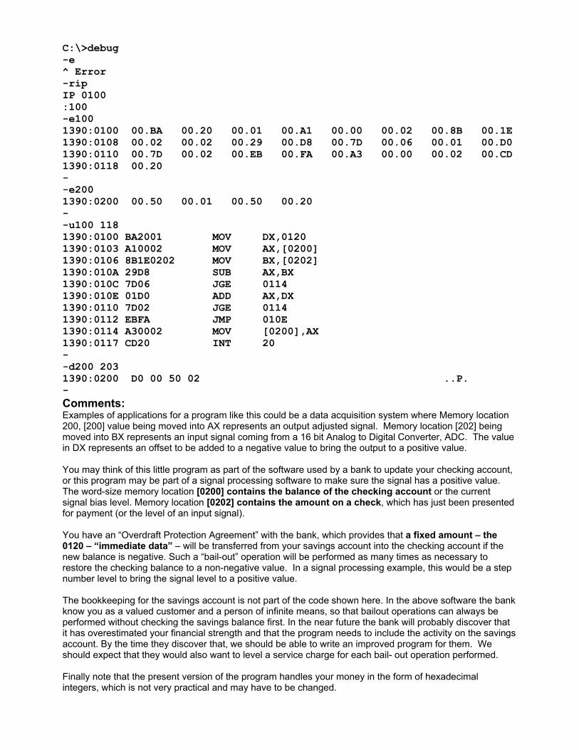
C:\>debug -e ^ Error -rip IP 0100 :100 -e100 1390:0100 00.BA 00.20 00.01 00.A1 00.00 00.02 00.8B 00.1E 1390:0108 00.02 00.02 00.29 00.D8 00.7D 00.06 00.01 00.D0 1390:0110 00.7D 00.02 00.EB 00.FA 00.A3 00.00 00.02 00.CD 1390:0118 00.20 - -e200 1390:0200 00.50 00.01 00.50 00.20 - -u100 118 1390:0100 BA2001 MOV DX,0120 1390:0103 A10002 MOV AX,[0200] 1390:0106 8B1E0202 MOV BX,[0202] 1390:010A 29D8 SUB AX,BX 1390:010C 7D06 JGE 0114 1390:010E 01D0 ADD AX,DX 1390:0110 7D02 JGE 0114 1390:0112 EBFA JMP 010E 1390:0114 A30002 MOV [0200],AX 1390:0117 CD20 INT 20 - -d200 203 1390:0200 D0 00 50 02 ..P. - Comments: Examples of applications for a program like this could be a data acquisition system where Memory location 200, [200] value being moved into AX represents an output adjusted signal. Memory location [202] being moved into BX represents an input signal coming from a 16 bit Analog to Digital Converter, ADC. The value in DX represents an offset to be added to a negative value to bring the output to a positive value. You may think of this little program as part of the software used by a bank to update your checking account, or this program may be part of a signal processing software to make sure the signal has a positive value. The word-size memory location [0200] contains the balance of the checking account or the current signal bias level. Memory location [0202] contains the amount on a check, which has just been presented for payment (or the level of an input signal). You have an “Overdraft Protection Agreement” with the bank, which provides that a fixed amount – the 0120 – “immediate data” – will be transferred from your savings account into the checking account if the new balance is negative. Such a “bail-out” operation will be performed as many times as necessary to restore the checking balance to a non-negative value. In a signal processing example, this would be a step number level to bring the signal level to a positive value. The bookkeeping for the savings account is not part of the code shown here. In the above software the bank know you as a valued customer and a person of infinite means, so that bailout operations can always be performed without checking the savings balance first. In the near future the bank will probably discover that it has overestimated your financial strength and that the program needs to include the activity on the savings account. By the time they discover that, we should be able to write an improved program for them. We should expect that they would also want to level a service charge for each bail- out operation performed. Finally note that the present version of the program handles your money in the form of hexadecimal integers, which is not very practical and may have to be changed.
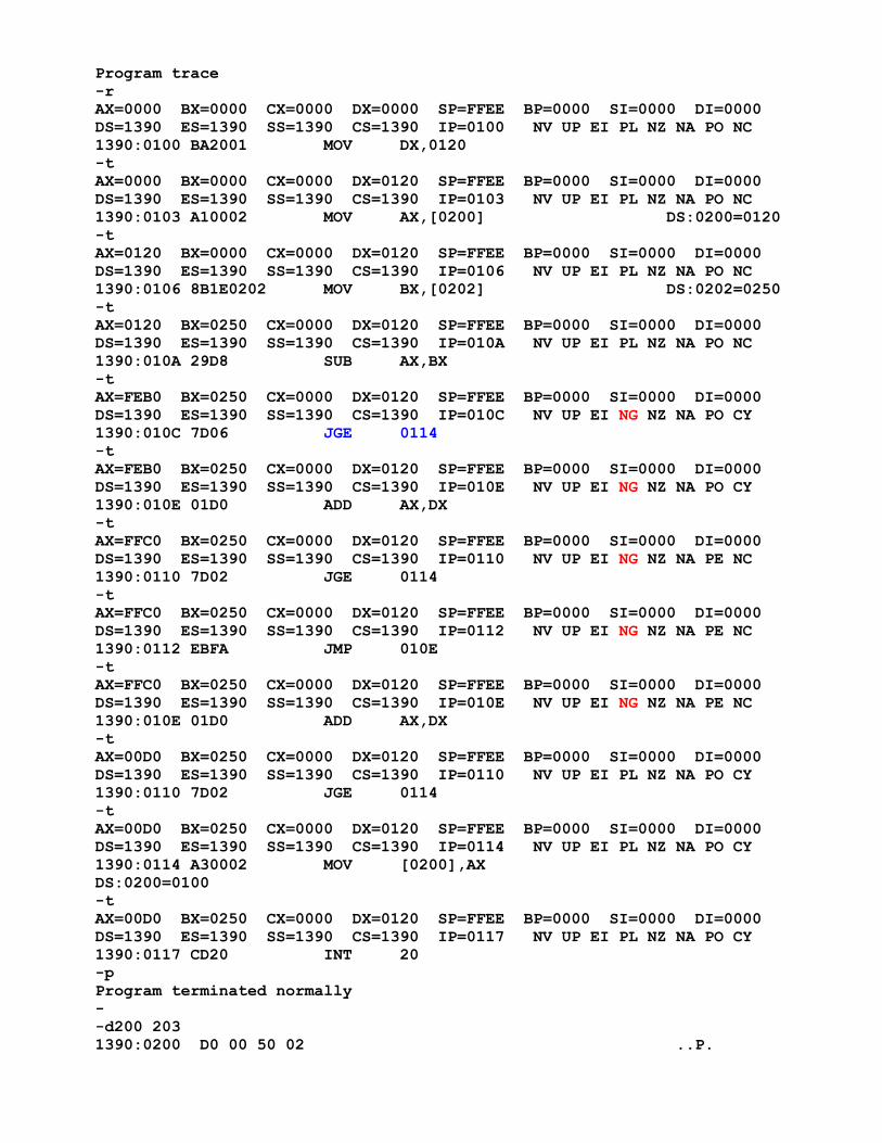
Program trace -r AX=0000 BX=0000 CX=0000 DX=0000 SP=FFEE BP=0000 SI=0000 DI=0000 DS=1390 ES=1390 SS=1390 CS=1390 IP=0100 NV UP EI PL NZ NA PO NC 1390:0100 BA2001 MOV DX,0120 -t AX=0000 BX=0000 CX=0000 DX=0120 SP=FFEE BP=0000 SI=0000 DI=0000 DS=1390 ES=1390 SS=1390 CS=1390 IP=0103 NV UP EI PL NZ NA PO NC 1390:0103 A10002 MOV AX,[0200] DS:0200=0120 -t AX=0120 BX=0000 CX=0000 DX=0120 SP=FFEE BP=0000 SI=0000 DI=0000 DS=1390 ES=1390 SS=1390 CS=1390 IP=0106 NV UP EI PL NZ NA PO NC 1390:0106 8B1E0202 MOV BX,[0202] DS:0202=0250 -t AX=0120 BX=0250 CX=0000 DX=0120 SP=FFEE BP=0000 SI=0000 DI=0000 DS=1390 ES=1390 SS=1390 CS=1390 IP=010A NV UP EI PL NZ NA PO NC 1390:010A 29D8 SUB AX,BX -t AX=FEB0 BX=0250 CX=0000 DX=0120 SP=FFEE BP=0000 SI=0000 DI=0000 DS=1390 ES=1390 SS=1390 CS=1390 IP=010C NV UP EI NG NZ NA PO CY 1390:010C 7D06 JGE 0114 -t AX=FEB0 BX=0250 CX=0000 DX=0120 SP=FFEE BP=0000 SI=0000 DI=0000 DS=1390 ES=1390 SS=1390 CS=1390 IP=010E NV UP EI NG NZ NA PO CY 1390:010E 01D0 ADD AX,DX -t AX=FFC0 BX=0250 CX=0000 DX=0120 SP=FFEE BP=0000 SI=0000 DI=0000 DS=1390 ES=1390 SS=1390 CS=1390 IP=0110 NV UP EI NG NZ NA PE NC 1390:0110 7D02 JGE 0114 -t AX=FFC0 BX=0250 CX=0000 DX=0120 SP=FFEE BP=0000 SI=0000 DI=0000 DS=1390 ES=1390 SS=1390 CS=1390 IP=0112 NV UP EI NG NZ NA PE NC 1390:0112 EBFA JMP 010E -t AX=FFC0 BX=0250 CX=0000 DX=0120 SP=FFEE BP=0000 SI=0000 DI=0000 DS=1390 ES=1390 SS=1390 CS=1390 IP=010E NV UP EI NG NZ NA PE NC 1390:010E 01D0 ADD AX,DX -t AX=00D0 BX=0250 CX=0000 DX=0120 SP=FFEE BP=0000 SI=0000 DI=0000 DS=1390 ES=1390 SS=1390 CS=1390 IP=0110 NV UP EI PL NZ NA PO CY 1390:0110 7D02 JGE 0114 -t AX=00D0 BX=0250 CX=0000 DX=0120 SP=FFEE BP=0000 SI=0000 DI=0000 DS=1390 ES=1390 SS=1390 CS=1390 IP=0114 NV UP EI PL NZ NA PO CY 1390:0114 A30002 MOV [0200],AX DS:0200=0100 -t AX=00D0 BX=0250 CX=0000 DX=0120 SP=FFEE BP=0000 SI=0000 DI=0000 DS=1390 ES=1390 SS=1390 CS=1390 IP=0117 NV UP EI PL NZ NA PO CY 1390:0117 CD20 INT 20 -p Program terminated normally - -d200 203 1390:0200 D0 00 50 02 ..P.
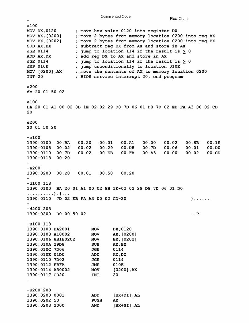
- a100 MOV DX,0120 ; move hex value 0120 into register DX MOV AX,[0200] ; move 2 bytes from memory location 0200 into reg AX MOV BX,[0202] ; move 2 bytes from memory location 0200 into reg BX SUB AX,BX ; subtract reg BX from AX and store in AX JGE 0114 ; jump to location 114 if the result is > 0 ADD AX,DX ; add reg DX to AX and store in AX JGE 0114 ; jump to location 114 if the result is > 0 JMP 010E ; jump unconditionally to location 010E MOV [0200],AX ; move the contents of AX to memory location 0200 INT 20 ; BIOS service interrupt 20, end program a200 db 20 01 50 02 e100 BA 20 01 A1 00 02 8B 1E 02 02 29 D8 7D 06 01 D0 7D 02 EB FA A3 00 02 CD 20 e200 20 01 50 20 -e100 1390:0100 00.BA 00.20 00.01 00.A1 00.00 00.02 00.8B 00.1E 1390:0108 00.02 00.02 00.29 00.D8 00.7D 00.06 00.01 00.D0 1390:0110 00.7D 00.02 00.EB 00.FA 00.A3 00.00 00.02 00.CD 1390:0118 00.20 - -e200 1390:0200 00.20 00.01 00.50 00.20 - -d100 118 1390:0100 BA 20 01 A1 00 02 8B 1E-02 02 29 D8 7D 06 01 D0 ..........).}... 1390:0110 7D 02 EB FA A3 00 02 CD-20 }....... - -d200 203 1390:0200 D0 00 50 02 ..P. - -u100 118 1390:0100 BA2001 MOV DX,0120 1390:0103 A10002 MOV AX,[0200] 1390:0106 8B1E0202 MOV BX,[0202] 1390:010A 29D8 SUB AX,BX 1390:010C 7D06 JGE 0114 1390:010E 01D0 ADD AX,DX 1390:0110 7D02 JGE 0114 1390:0112 EBFA JMP 010E 1390:0114 A30002 MOV [0200],AX 1390:0117 CD20 INT 20 - -u200 203 1390:0200 0001 ADD [BX+DI],AL 1390:0202 50 PUSH AX 1390:0203 2000 AND [BX+SI],AL
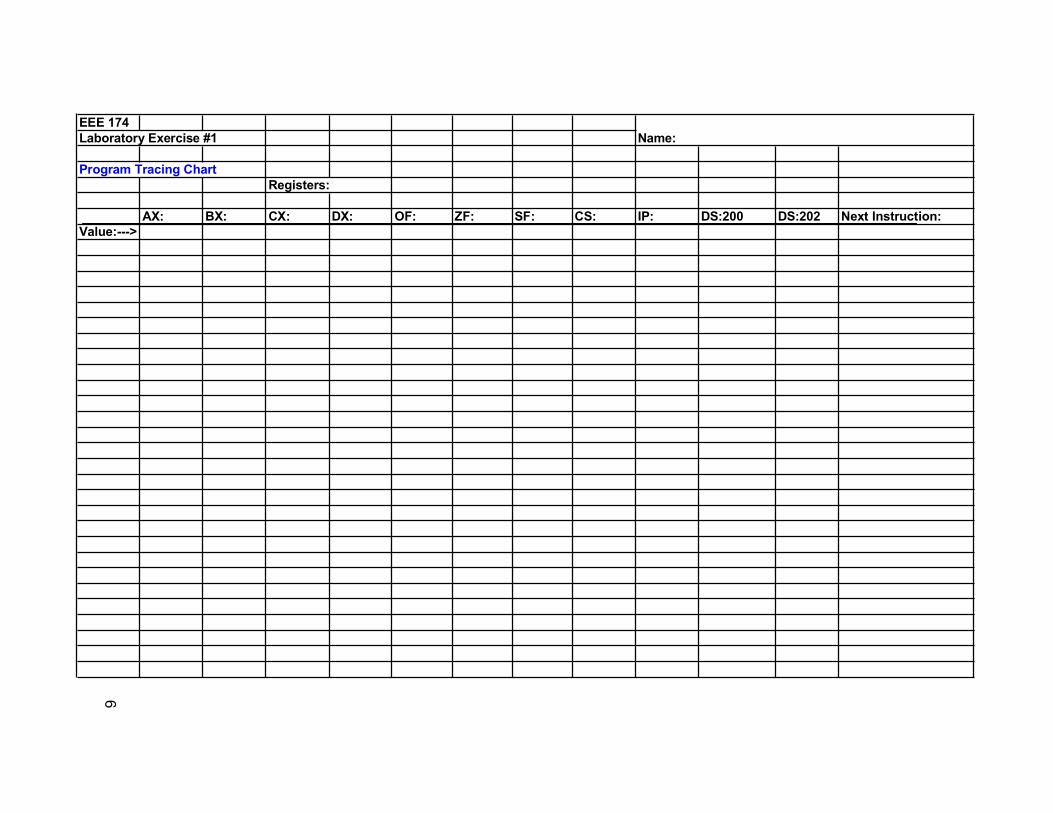
EEE 174Laboratory Exercise #1 Name:
Program Tracing Chart Registers:
AX: BX: CX: DX: OF: ZF: SF: CS: IP: DS:200 DS:202 Next Instruction:Value:--->
68
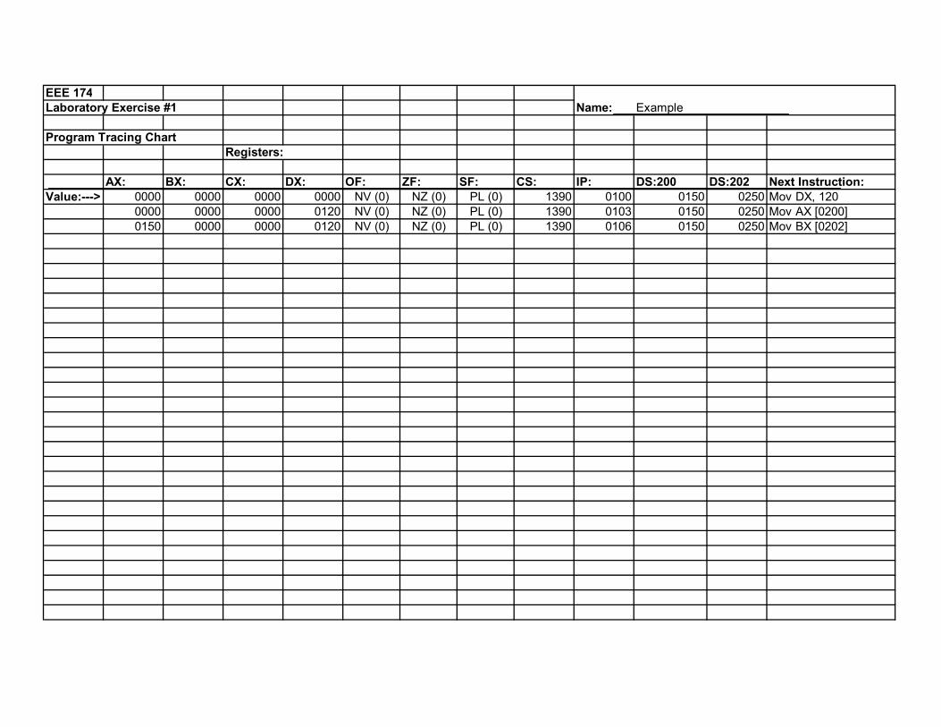
EEE 174Laboratory Exercise #1 Name: Example
Program Tracing Chart Registers:
AX: BX: CX: DX: OF: ZF: SF: CS: IP: DS:200 DS:202 Next Instruction:Value:---> 0000 0000 0000 0000 NV (0) NZ (0) PL (0) 1390 0100 0150 0250 Mov DX, 120
0000 0000 0000 0120 NV (0) NZ (0) PL (0) 1390 0103 0150 0250 Mov AX [0200]0150 0000 0000 0120 NV (0) NZ (0) PL (0) 1390 0106 0150 0250 Mov BX [0202]
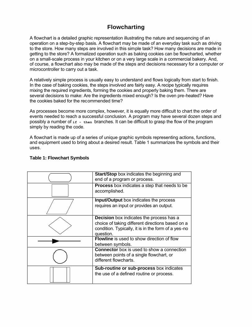
Flowcharting A flowchart is a detailed graphic representation illustrating the nature and sequencing of an operation on a step-by-step basis. A flowchart may be made of an everyday task such as driving to the store. How many steps are involved in this simple task? How many decisions are made in getting to the store? A formalized operation such as baking cookies can be flowcharted, whether on a small-scale process in your kitchen or on a very large scale in a commercial bakery. And, of course, a flowchart also may be made of the steps and decisions necessary for a computer or microcontroller to carry out a task. A relatively simple process is usually easy to understand and flows logically from start to finish. In the case of baking cookies, the steps involved are fairly easy. A recipe typically requires mixing the required ingredients, forming the cookies and properly baking them. There are several decisions to make: Are the ingredients mixed enough? Is the oven pre-heated? Have the cookies baked for the recommended time? As processes become more complex, however, it is equally more difficult to chart the order of events needed to reach a successful conclusion. A program may have several dozen steps and possibly a number of if - then branches. It can be difficult to grasp the flow of the program simply by reading the code. A flowchart is made up of a series of unique graphic symbols representing actions, functions, and equipment used to bring about a desired result. Table 1 summarizes the symbols and their uses. Table 1: Flowchart Symbols
Start/Stop box indicates the beginning and end of a program or process.
Process box indicates a step that needs to be accomplished.
Input/Output box indicates the process requires an input or provides an output.
Decision box indicates the process has a choice of taking different directions based on a condition. Typically, it is in the form of a yes-no question.
Flowline is used to show direction of flow between symbols.
Connector box is used to show a connection between points of a single flowchart, or different flowcharts.
Sub-routine or sub-process box indicates the use of a defined routine or process.
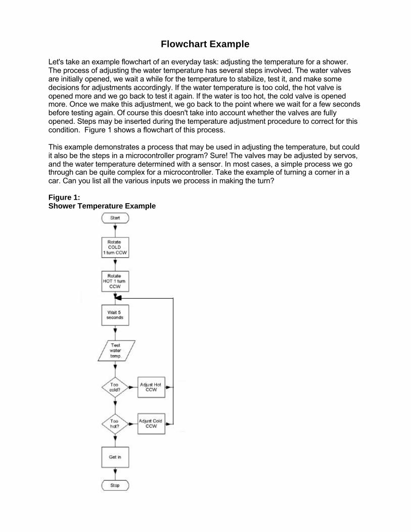
Flowchart Example Let's take an example flowchart of an everyday task: adjusting the temperature for a shower. The process of adjusting the water temperature has several steps involved. The water valves are initially opened, we wait a while for the temperature to stabilize, test it, and make some decisions for adjustments accordingly. If the water temperature is too cold, the hot valve is opened more and we go back to test it again. If the water is too hot, the cold valve is opened more. Once we make this adjustment, we go back to the point where we wait for a few seconds before testing again. Of course this doesn't take into account whether the valves are fully opened. Steps may be inserted during the temperature adjustment procedure to correct for this condition. Figure 1 shows a flowchart of this process. This example demonstrates a process that may be used in adjusting the temperature, but could it also be the steps in a microcontroller program? Sure! The valves may be adjusted by servos, and the water temperature determined with a sensor. In most cases, a simple process we go through can be quite complex for a microcontroller. Take the example of turning a corner in a car. Can you list all the various inputs we process in making the turn? Figure 1: Shower Temperature Example
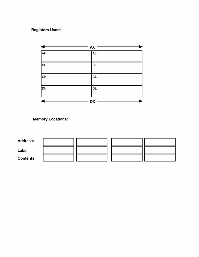
AH AL
BH BL
CH CL
DH DL
AX
DX
Registers Used:
Memory Locations:
Address:
Label:
Contents:
8
1234567891011121314151617181920212223242526272829303132333435363738394041424344454647484950515253545556575859606162636465666768697071
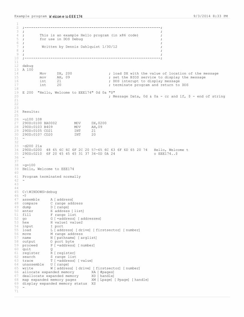
;---------------------------------------------------------------;; ;; This is an example Hello program (in x86 code) ;; for use in DOS Debug ;; ;; Written by Dennis Dahlquist 1/30/12 ;; ;; ;;---------------------------------------------------------------;
debugA 100
Mov DX, 200 ; load DX with the value of location of the messagemov AH, 09 ; set the BIOS service to display the messageint 21 ; DOS interupt to display messageint 20 ; terminate program and return to DOS
E 200 "Hello, Welcome to EEE174" 0d 0a "$" ; Message Data, 0d & 0a - cr and lf, $ - end of string
Results:
-u100 108290D:0100 BA0002 MOV DX,0200290D:0103 B409 MOV AH,09290D:0105 CD21 INT 21290D:0107 CD20 INT 20-
-d200 21a290D:0200 48 65 6C 6C 6F 2C 20 57-65 6C 63 6F 6D 65 20 74 Hello, Welcome t290D:0210 6F 20 45 45 45 31 37 34-0D 0A 24 o EEE174..$-
-g=100Hello, Welcome to EEE174
Program terminated normally-
C:\WINDOWS>debug-?assemble A [address]compare C range addressdump D [range]enter E address [list]fill F range listgo G [=address] [addresses]hex H value1 value2input I portload L [address] [drive] [firstsector] [number]move M range addressname N [pathname] [arglist]output O port byteproceed P [=address] [number]quit Qregister R [register]search S range listtrace T [=address] [value]unassemble U [range]write W [address] [drive] [firstsector] [number]allocate expanded memory XA [#pages]deallocate expanded memory XD [handle]map expanded memory pages XM [Lpage] [Ppage] [handle]display expanded memory status XS-
Example program 9/3/2014 8:33 PM
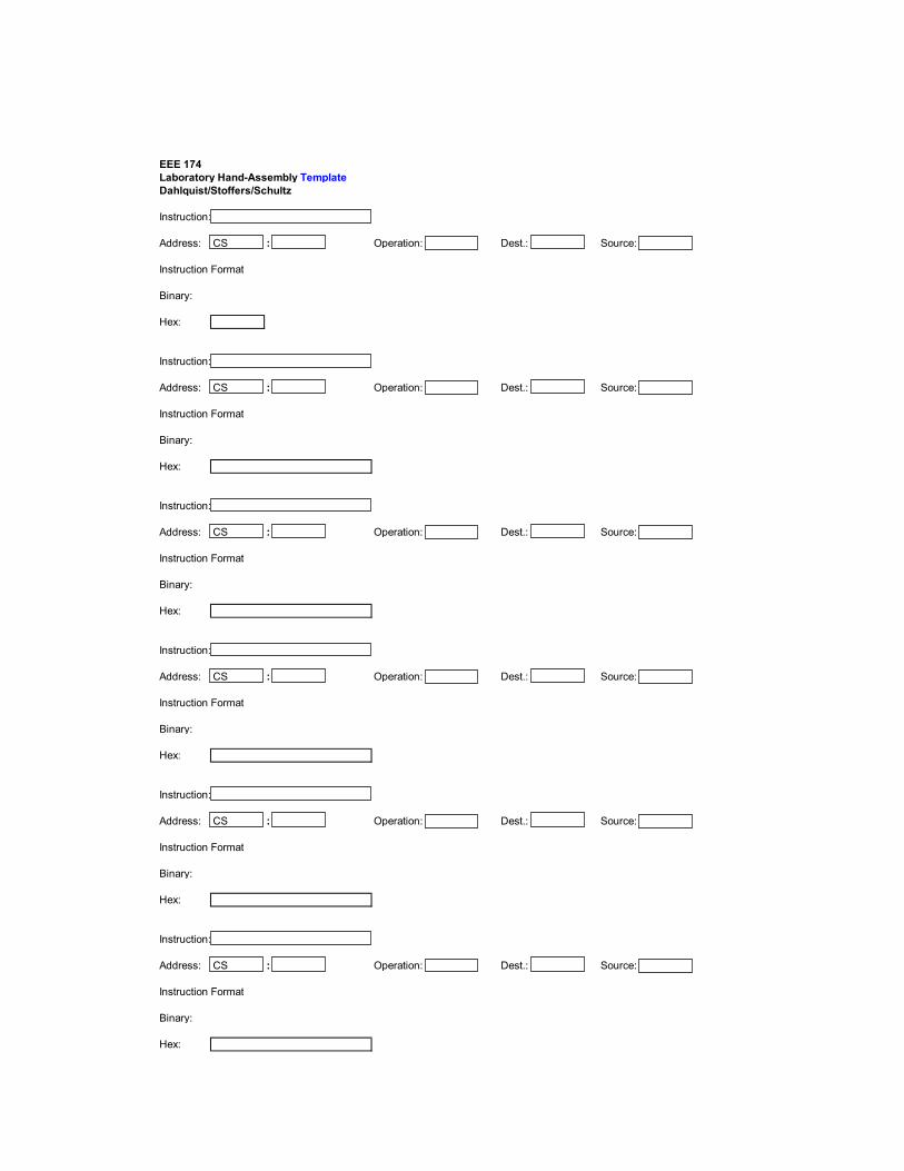
EEE 174Laboratory Hand-Assembly TemplateDahlquist/Stoffers/Schultz Instruction:
Address: CS : Operation: Dest.: Source:
Instruction Format
Binary:
Hex:
Instruction:
Address: CS : Operation: Dest.: Source:
Instruction Format
Binary:
Hex:
Instruction:
Address: CS : Operation: Dest.: Source:
Instruction Format
Binary:
Hex:
Instruction:
Address: CS : Operation: Dest.: Source:
Instruction Format
Binary:
Hex:
Instruction:
Address: CS : Operation: Dest.: Source:
Instruction Format
Binary:
Hex:
Instruction:
Address: CS : Operation: Dest.: Source:
Instruction Format
Binary:
Hex:
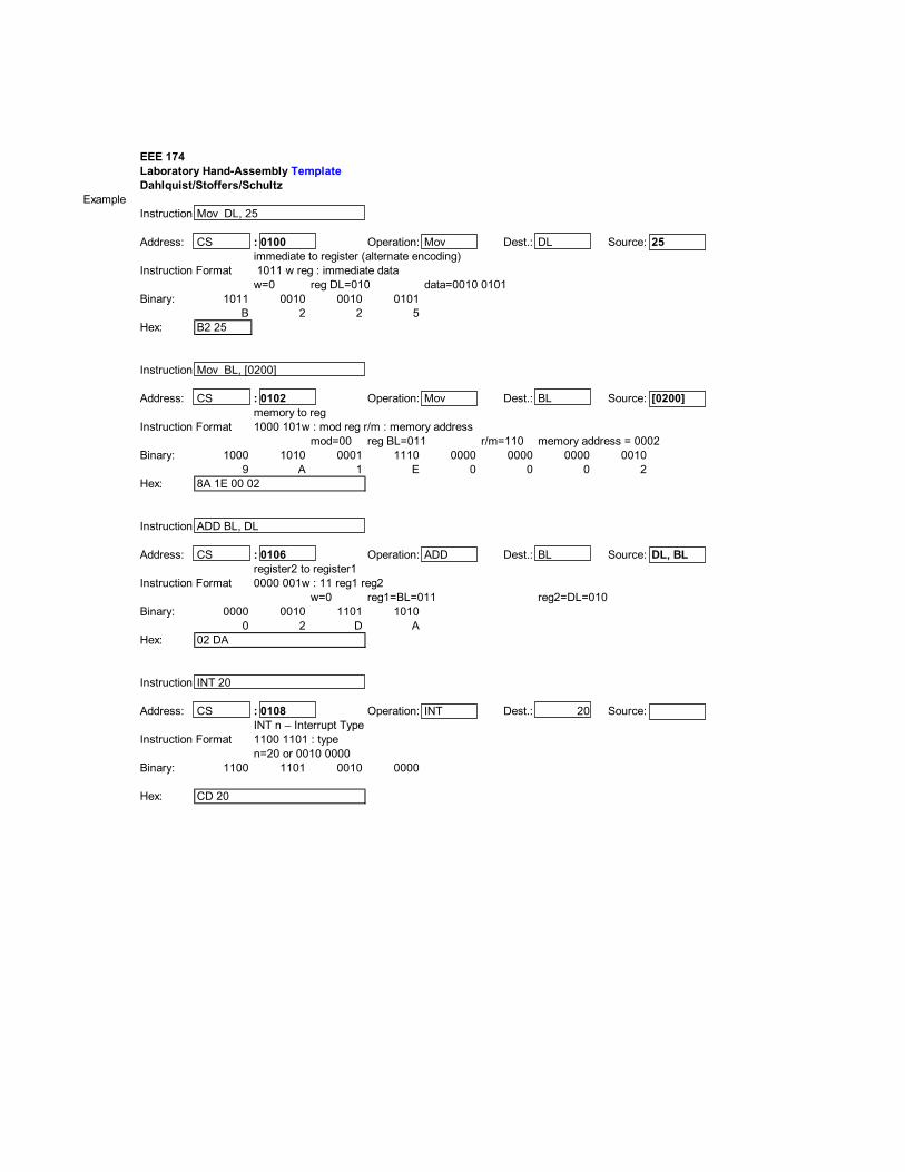
EEE 174Laboratory Hand-Assembly TemplateDahlquist/Stoffers/Schultz
Example Instruction:Mov DL, 25
Address: CS : 0100 Operation: Mov Dest.: DL Source: 25immediate to register (alternate encoding)
Instruction Format w=0 reg DL=010 data=0010 0101
Binary: 1011 0010 0010 0101B 2 2 5
Hex: B2 25
Instruction:Mov BL, [0200]
Address: CS : 0102 Operation: Mov Dest.: BL Source: [0200]
Instruction Format mod=00 reg BL=011 r/m=110
Binary: 1000 1010 0001 1110 0000 0000 0000 00109 A 1 E 0 0 0 2
Hex:
Instruction:ADD BL, DL
Address: CS : 0106 Operation: ADD Dest.: BL Source: DL, BL
Instruction Format w=0 reg1=BL=011
Binary: 0000 0010 1101 10100 2 D A
Hex:
Instruction:INT 20
Address: CS : 0108 Operation: INT Dest.: 20 Source:INT n – Interrupt Type n
Instruction Format n=20 or 0010 0000
Binary: 1100 1101 0010 0000
Hex:
1100 1101 : type
CD 20
register2 to register1 0000 001w : 11 reg1 reg2
reg2=DL=010
02 DA
1011 w reg : immediate data
memory to reg 1000 101w : mod reg r/m : memory address
8A 1E 00 02
memory address = 0002
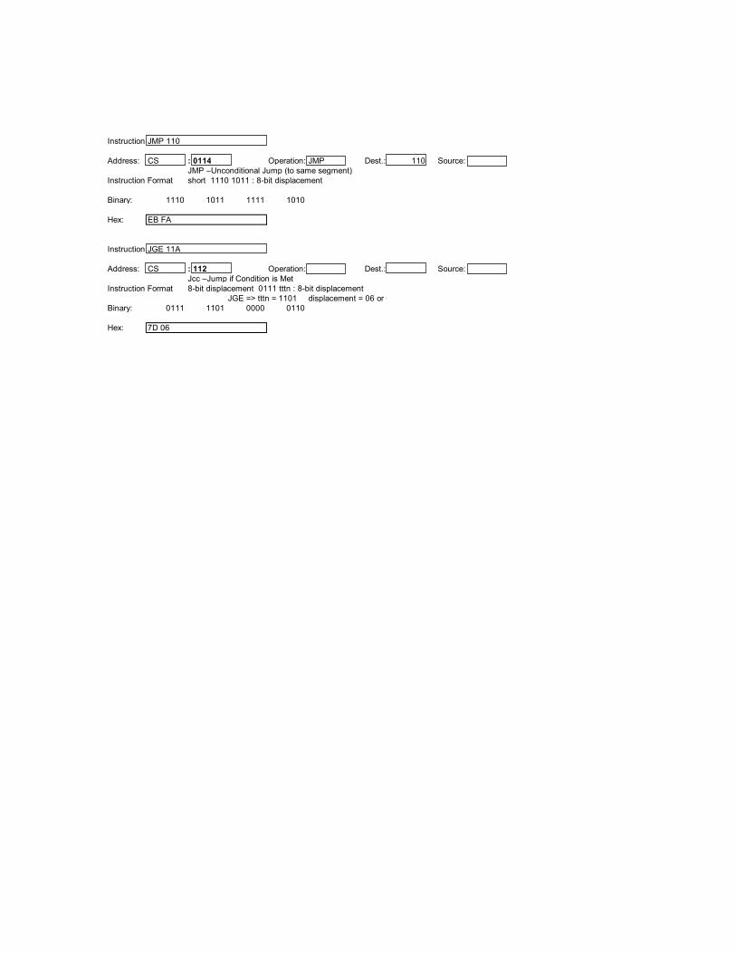
Instruction:JMP 110
Address: CS : 0114 Operation: JMP Dest.: 110 Source:JMP –Unconditional Jump (to same segment)
Instruction Format
Binary: 1110 1011 1111 1010
Hex:
Instruction:JGE 11A
Address: CS : 112 Operation: Dest.: Source:Jcc –Jump if Condition is Met
Instruction Format JGE => tttn = 1101 displacement = 06 or 0000 0110
Binary: 0111 1101 0000 0110
Hex: 7D 06
short 1110 1011 : 8-bit displacement
EB FA
8-bit displacement 0111 tttn : 8-bit displacement
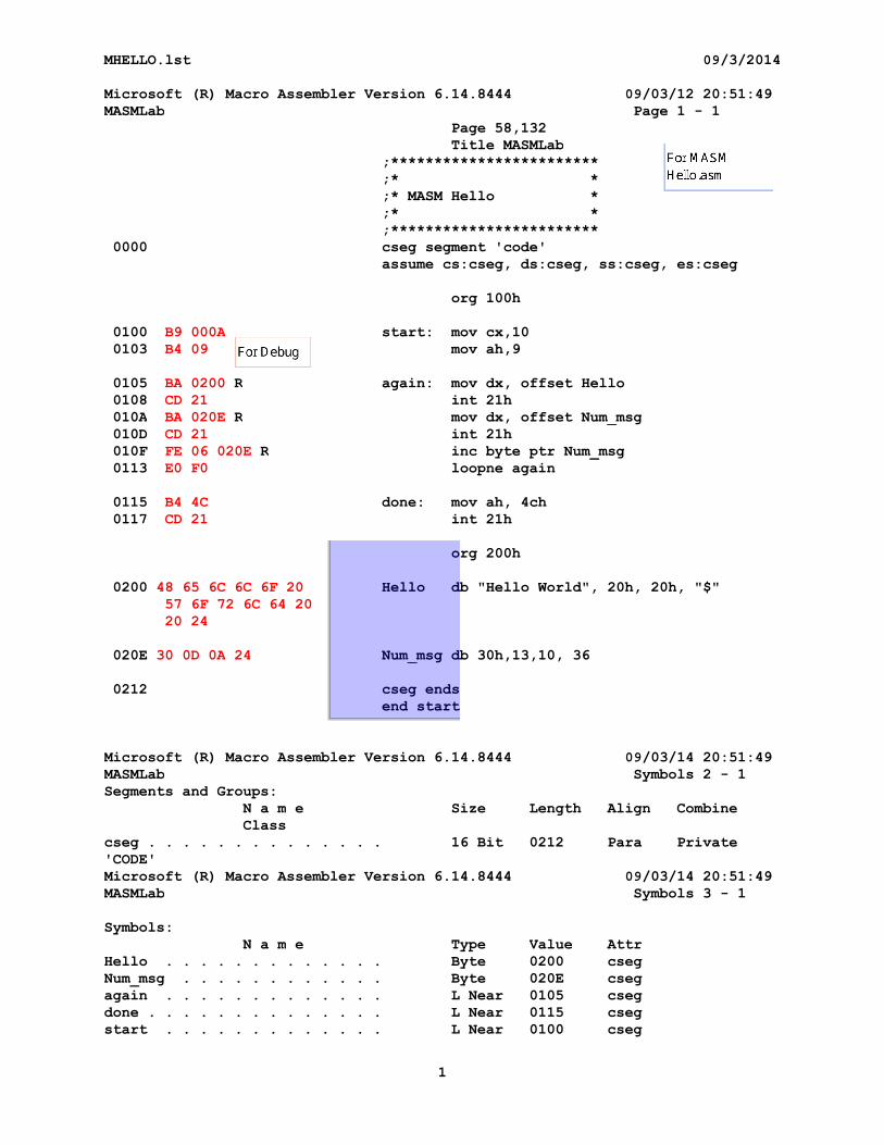
MHELLO.lst 09/3/2014
Microsoft (R) Macro Assembler Version 6.14.8444 09/03/12 20:51:49MASMLab Page 1 - 1
Page 58,132Title MASMLab
;************************;* *;* MASM Hello *;* *;************************
0000 cseg segment 'code'assume cs:cseg, ds:cseg, ss:cseg, es:cseg
org 100h
0100 B9 000A start: mov cx,100103 B4 09 mov ah,9
0105 BA 0200 R again: mov dx, offset Hello0108 CD 21 int 21h010A BA 020E R mov dx, offset Num_msg010D CD 21 int 21h010F FE 06 020E R inc byte ptr Num_msg0113 E0 F0 loopne again
0115 B4 4C done: mov ah, 4ch0117 CD 21 int 21h
org 200h
0200 48 65 6C 6C 6F 20 Hello db "Hello World", 20h, 20h, "$"57 6F 72 6C 64 2020 24
020E 30 0D 0A 24 Num_msg db 30h,13,10, 36
0212 cseg endsend start
Microsoft (R) Macro Assembler Version 6.14.8444 09/03/14 20:51:49MASMLab Symbols 2 - 1Segments and Groups:
N a m e Size Length Align CombineClass
cseg . . . . . . . . . . . . . . 16 Bit 0212 Para Private'CODE'Microsoft (R) Macro Assembler Version 6.14.8444 09/03/14 20:51:49MASMLab Symbols 3 - 1
Symbols:N a m e Type Value Attr
Hello . . . . . . . . . . . . . Byte 0200 csegNum_msg . . . . . . . . . . . . Byte 020E csegagain . . . . . . . . . . . . . L Near 0105 csegdone . . . . . . . . . . . . . . L Near 0115 csegstart . . . . . . . . . . . . . L Near 0100 cseg
1
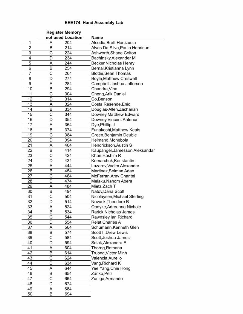
EEE174 Hand Assembly Lab
Register not used
Memory Location Name
1 A 204 Alcodia,Brett Hortizuela2 B 214 Alves Da Silva,Paulo Henrique3 C 224 Ashworth,Shane Colton4 D 234 Bachinsky,Alexander M5 A 244 Becker,Nicholas Henry6 B 254 Bernal,Kristianna Lynn7 C 264 Blottie,Sean Thomas8 D 274 Boyle,Matthew Creswell9 A 284 Campbell,Joshua Jefferson10 B 294 Chandra,Vina11 C 304 Cheng,Arik Daniel12 D 314 Co,Benson13 A 324 Costa Resende,Enio14 B 334 Douglas-Allen,Zachariah15 C 344 Downey,Matthew Edward16 D 354 Downey,Vincent Antenor17 A 364 Dye,Phillip J18 B 374 Funakoshi,Matthew Keats19 C 384 Green,Benjamin Deuble20 D 394 Helmand,Mohebola21 A 404 Hendrickson,Austin S22 B 414 Kaupanger,Jamesson Aleksandar23 C 424 Khan,Hashim R24 D 434 Komarchuk,Konstantin I25 A 444 Lazarev,Vadim Alexander26 B 454 Martinez,Selman Adan27 C 464 McFerran,Amy Chantel28 D 474 Melaku,Nahom Abera29 A 484 Mietz,Zach T30 B 494 Natov,Dana Scott31 C 504 Nicolaysen,Michael Sterling32 D 514 Novack,Theodore B33 A 524 Opdyke,Adreanna Nichole34 B 534 Rarick,Nicholas James35 C 544 Rawnsley,Ian Richard36 D 554 Relat,Charles A37 A 564 Schumann,Kenneth Glen38 B 574 Scott II,Drew Lewis39 C 584 Scott,Joshua James40 D 594 Solak,Alexandra E41 A 604 Thorng,Rothana42 B 614 Truong,Victor Minh43 C 624 Valencia,Aurelio44 D 634 Vang,Richard K45 A 644 Yee Yang,Chie Hong46 B 654 Zanko,Petr47 C 664 Zuniga,Armando48 D 67449 A 68450 B 694
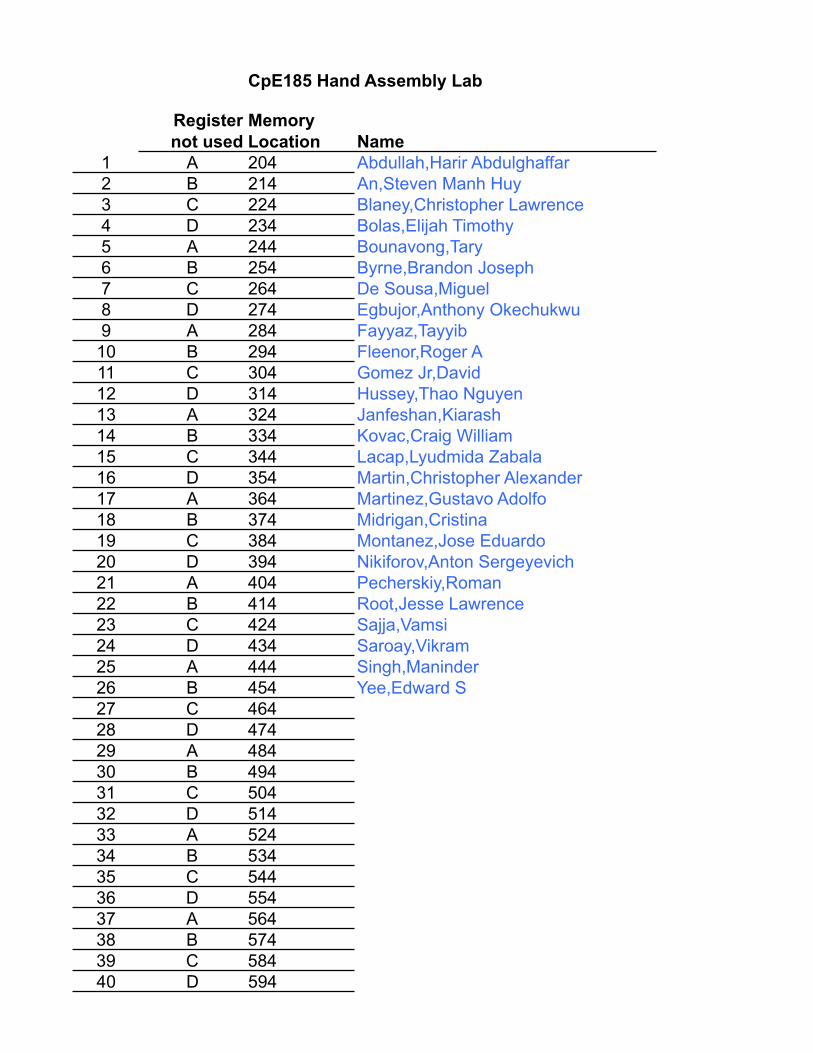
CpE185 Hand Assembly Lab
Register not used
Memory Location Name
1 A 204 Abdullah,Harir Abdulghaffar2 B 214 An,Steven Manh Huy3 C 224 Blaney,Christopher Lawrence4 D 234 Bolas,Elijah Timothy5 A 244 Bounavong,Tary6 B 254 Byrne,Brandon Joseph7 C 264 De Sousa,Miguel8 D 274 Egbujor,Anthony Okechukwu9 A 284 Fayyaz,Tayyib10 B 294 Fleenor,Roger A11 C 304 Gomez Jr,David12 D 314 Hussey,Thao Nguyen13 A 324 Janfeshan,Kiarash14 B 334 Kovac,Craig William15 C 344 Lacap,Lyudmida Zabala16 D 354 Martin,Christopher Alexander17 A 364 Martinez,Gustavo Adolfo18 B 374 Midrigan,Cristina19 C 384 Montanez,Jose Eduardo20 D 394 Nikiforov,Anton Sergeyevich21 A 404 Pecherskiy,Roman22 B 414 Root,Jesse Lawrence23 C 424 Sajja,Vamsi24 D 434 Saroay,Vikram25 A 444 Singh,Maninder26 B 454 Yee,Edward S27 C 46428 D 47429 A 48430 B 49431 C 50432 D 51433 A 52434 B 53435 C 54436 D 55437 A 56438 B 57439 C 58440 D 594