Embed Size (px)
Citation preview
Precious metal core-shell spindles
X. Xu and M.B. Cortie
Institute for Nanoscale Technology, University of Technology Sydney, Australia
Key words: silver nanoparticles, hematite, optical properties, core-shell
PO Box 123, Broadway, NSW 2007, Australia
Tel +61 2 9514 2208, Fax +61 2 95147553
Email: [email protected]

Abstract
A simplified method to produce spindle-shaped particles with a hematite core and a silica shell is
described. The silica shell can, in turn, serve as the substrate for an outer coating of Ag or Au
nanoparticles. The resulting multi-layer core-shell particles display a flexible optical extinction
spectrum, due primarily to the sensitivity of their plasmon resonance to the morphology of the
precious metal outer coating.

Xiaoda Xu and M.B. Cortie *
J. Phys. Chem. C
Silver and gold nanoshells on spindle-shaped
particles
The deposition of silver or gold onto spindle-
shaped cores produces particles with distinctive optical properties. A silica
interlayer between core and shell facilitates
attachment of the precious metal. The
morphology of the metal coating can be
controlled by adjustment of the deposition
conditions, and controls the optical extinction
characteristics.
Introduction
Precious metal nanoparticles such as gold or silver nanorods1,2
, nanoshells3, and nanocaps
4,5 have
attracted considerable attention recently. These particles are of particular interest for potential or
actual optical applications due to their unique surface plasmon resonances6. The nature and position
of the resonances is directly determined by the geometry and composition of the particles, allowing
considerable tunability in optical response. In the present paper we explore and extend
understanding of a very recently developed new design of core-shell particle: the ‘nanorice’7. This
interesting particle has properties intermediate between those of nanorods and nanoshells.
Gold and silver nanoshells of less than about 100 nm diameter have a single, strongly developed,
extinction peak that can be tuned across the visible and infrared regions of the spectrum by
adjusting the ratio of shell thickness to outer diameter of particle8,9
. While various methods of
synthesis have been reported, the mainstream route, as pioneered by the Halas group in the USA, is
to use silica nanoparticles as cores, functionalize the surface of the cores with a reagent such as
aminopropyltriethoxysilane, attach colloidal gold seeds, and then grow the seeds to coalescence10
.
There has been particular interest in using these particles in medical applications, and
experimentation along these lines is well advanced11-15
.
Gold nanorods of less than about 150 nm length have two surface plasmon resonance peaks, one
due to a longitudinal plasmon and the other to transverse plasmons. The position of the longitudinal
peak may be adjusted by control of the aspect ratio1,2
and morphology16,17
. This feature may be
exploited in the application of surface plasmons in spectrally selective coatings18
, metal-enhanced
fluorescence19
, Raman spectroscopy20
, and photothermal medical treatments21,22
. So far, almost all
the methods of making such particles by wet chemistry use a surfactant such as cetyltetra-
ammonium bromide (CTAB) and gold ‘seed’ particles23
. The surfactant acts as a “soft template”24
to nucleate the shape and to form a protecting layer to stabilize the particles25
. Unfortunately, the
CTAB molecules are strongly attached to the surface of the gold nanorods, and are difficult to
remove by washing18
. Such particles cannot be readily re-dispersed organic solvents26
, which would
be a desirable attribute for many of the proposed applications26
. Complicated procedures, such as
multi-step polyelectrolytic coating26,27
, are currently required to replace the CTAB with another
surfactant before the particles can be stabilized in, for example, ethanol solution.
A ‘nanorice’ particle is elongated like a nanorod but comprised of a precious metal coating on a
dielectric core. The plasmonic properties of this hybrid morphology are intermediate in nature
between those of spherical nanoshells and of nanorods7. As for nanoshells (for example ref.
28), a
sparse coating of precious metal particles on the core, as opposed to a continuous shell, may also be
readily obtained if desired, providing a convenient way to control the dipole-dipole interactions of
closely spaced precious metal nanoparticles. In general, dipole-dipole interactions red-shift and
broaden the plasmon resonance.28-30
. This has potential application in, for example, spectrally
selective coatings for windows31
. The ‘nanorice’ concept offers a uniquely flexible platform to
blend all of the flexibility of nanorods, nanoshells and dipole-dipole interactions into a single
product, and potentially offers the most flexible optical gamut of any known particle. (Note that the
term ‘nano-rice’ has also subsequently been applied in the literature32
to elongated nanoparticles
that are comprised of a single material. This usage of the word appears inconsistent with the intent
of the founding definition7 of Wang et al.)
A basic problem when attempting to prepare nanorice (or indeed any core-shell particle) by wet
chemical means is to achieve nucleation and growth of the plasmonically-active gold or silver shell
on the dielectric core. This is because surface energy considerations generally inhibit the attachment
of Au or Ag nuclei to candidate dielectric core materials. (This problem can be overcome by
synthesizing the particles in a high temperature, highly reducing, organic environment, e.g.33
, but
this is not for the faint-hearted.) In the original7 synthesis of the nanorice particles, the problem was
solved by functionalizing the surface of the Fe2O3 core with 3-aminopropyl trimethoxysilane
(APTMS), so that colloidal Au seed crystals could be attached. The gold seeds were then grown to
form a continuous shell. Similarly, the silane molecules serve as an interlayer between the core
material and the gold seeds. The formation of a covalent bond between the core particle and the
gold/silver seed is an essential attribute of this process. However, in the present work we
demonstrate an alternative, possibly more convenient, way to attach gold or silver particles to an
oxide substrate, and we analyze the factors that influence the microstructure and optical properties
of the resulting structures.
Experimental
The basic principle is to facilitate the attachment of the precious metal by first coating the
dielectric core particle with a smooth coating of SiO2 using the Stöber method34
. The shape, and
many other properties, of the core particles are preserved during this process. Actually, the idea of
encapsulating nanoparticles with a SiO2 overlayer is not new, having been pioneered by the
Mulvaney group (if not others) in the late 1990s35-38
. Furthermore, deposition of silver or gold on
silica is a well-known technology39,40
. For example, silver and gold films have been applied on
glass or silica surfaces electrolessly, for example as reflective mirrors41
or as prototype solar-
blocking glazing31
.
Materials
Ferric chloride hexahydrate (FeCl3.6H2O), potassium dihydrogen phosphate (KH2PO4), tetraethyl
orthosilicate (TEOS), 2-propanol, concentrated ammonium hydroxide solution (~ 17 M), stannous
chloride dihydrate (SnCl2.2H2O), hydrochloric acid (HCl), silver nitrate (AgNO3) and formaldehyde
(CH2O) were ordered from Sigma-Aldrich. All chemicals were reagent grade and used without
further purification. All water used was purified by Milli Q system and had an electrical resistance
of 18.4 MΩ/cm.
Procedure for making spindle-shaped, silica-coated hematite nanoparticles
a. Hematite spindles
The hematite particles were synthesized through hydrolysis of ferric chloride hexahydrate, a
procedure reported by Ohmori et al.42
. The method is briefly described here: 150 mL of aqueous
solution containing 20 mM FeCl3 and 0.4 mM KH2PO4 was aged at 100oC for 48 hours. The orange
slurry obtained was then centrifuged three times to remove the excess ions. The particles were re-
dispersed in 20 mL water. The product contained ~20 mg/mL of hematite particles.
b. Silica coating
Silica-coated hematite particles were prepared with the modified Stöber method by controlled
hydrolysis of silane in the presence of alcohol43
. Between 2.0 and 5.0 mL (~40 to 100 mg) hematite
colloid was mixed with 50 mL concentrated ammonium hydroxide (~ 17 M), 50 mL H2O and 200
mL 2-propanol. Then, 1.0 mL TEOS was added with vigorous stirring. The mixture was then held
at 40oC in a water bath for various times. The colloid was purified by centrifuging twice, and then
re-dispersed in 30 mL water. The colloid contained 0.1 ~ 0.3 mg/mL of silica-coated hematite
particles. The thickness of shell can be controlled by varying the ratio of hematite particles and
TEOS introduced and/or by varying the reaction time
Procedure for deposition of silver and gold
a. Stannous chloride pre-treatment
The silica-coated hematite particles were ‘sensitized’ with stannous chloride, a treatment that
facilitates the subsequent nucleation of precious metal onto an otherwise inert substrate, e.g.40
Due
to the large specific area of the nanoparticles, a comparatively large amount of SnCl2 must be used
to obtain reasonable coverage. Typically, 3 mg of silica-coated hematite (10 mL colloid as
prepared) was transferred into 20 mL of 0.2% SnCl2.2H2O aqueous solution. The pH of the solution
was adjusted to 1.5~3 by 1 M HCl to avoid hydrolysis and oxidation of SnCl2. The mixture was
magnetically stirred for an hour before it was centrifuged twice to remove the excess of SnCl2 and
other ions in the solution. The particles that had been pretreated with SnCl2 were redispersed in 15
mL of water. Therefore, the resulting colloid contained 0.2 mg/mL silica-coated hematite particles.
b. Silver deposition
The solution used to deposit Ag onto the silica-coated hematite particles had 0.25 ~ 2 mM
AgNO3, 0.23 M NH4OH solution and 6 ~ 13 mM CH2O. Usually, 0.03 ~ 0.2 mg of Sn-activated
particles were introduced into 5 mL of such solution. The deposition solution stayed stable during
the reaction since it contained a high concentration of ammonia. Once contacted with the colloid,
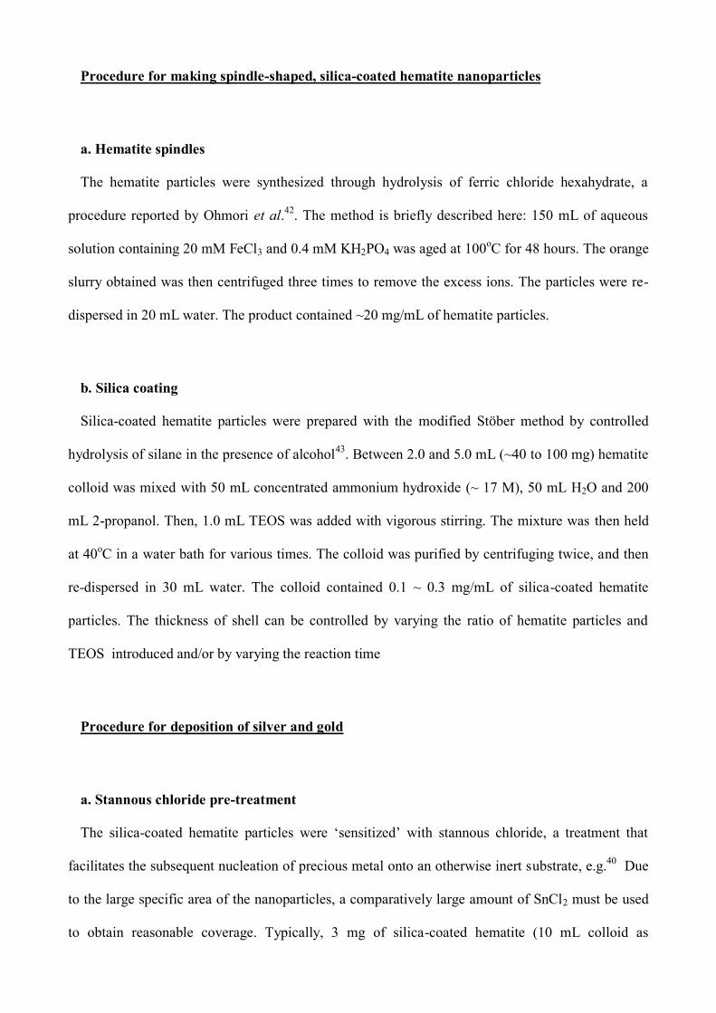
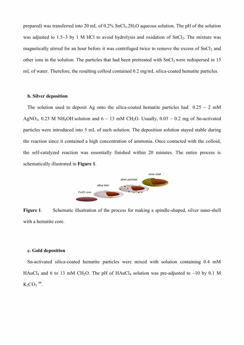
the self-catalyzed reaction was essentially finished within 20 minutes. The entire process is
schematically illustrated in Figure 1.
Figure 1. Schematic illustration of the process for making a spindle-shaped, silver nano-shell
with a hematite core.
c. Gold deposition
Sn-activated silica-coated hematite particles were mixed with solution containing 0.4 mM
HAuCl4 and 6 to 13 mM CH2O. The pH of HAuCl4 solution was pre-adjusted to ~10 by 0.1 M
K2CO3 44
.
Materials characterization
The morphologies of the samples were studied in a Zeiss Supra 55VP LEO scanning electron
microscope at 20 KV. The novel in-lens detector of the instrument provides 2 nm spatial resolution
and excellent contrast of multi-layer nanostructures. UV-visible absorption spectra were obtained
from a Shimadzu 1240 mini UV-Visible absorption spectrometer in the wavelength range 300 ~
1100 nm. The spectra were obtained at scanning speed of 600 nm/min with its spectral bandwidth
(SBW) of 5 nm. X-ray Photoelectron Spectroscopy (XPS) was utilized to determine the chemical
composition of the particles’ surface. The colloidal samples were dried in a desiccator overnight
before being measured in the XPS instrument. XPS spectra were recorded by using Al (K)
radiation (1486.6 eV) at 50 eV. The datasets obtained were calibrated with the carbon peak (285
eV) to counteract the effect of static charge. The crystal structure of the core-shell composites was
characterized with a Siemens Z6000 X-ray diffractrometer using a copper target at 40 kV. The
samples were scanned from 15~85o (2) with a step size of 0.02
o.
Simulation of optical properties
Some insight into the optical properties of the Ag-coated spindles was obtained by simulations
using DDSCAT, a code based on the discrete dipole approximation45,46
. Although computationally
intensive, this code will give usable results for arbitrary-shaped targets provided that the dipole
volume used is small enough. Unfortunately, the total volume of the Fe2O3 core, the silica shell and
the Ag outer coating was too great to satisfy this criterion within the memory limitations of the
computers used, and also because the length of time taken for DDSCAT to converge depends on the
third power of the number of dipoles used47
. To render the problem tractable, only the Ag portion of
the particle was simulated. We submit that this is acceptable, since it is only the Ag portion that
undergoes the plasmon resonance in the visible part of the spectrum, with the remainder of the
particle only serving to red-shift the plasmon phenomena somewhat. A dipole volume of about 18
nm3 was thus obtained, sufficiently small to provide an indication of the general trends. The
extinction efficiencies shown are the average of a transverse and longitudinal orientation of each
target.
Results
Evolution of particle morphology
a. Morphology of hematite spindle particles
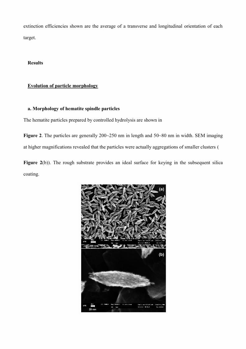
The hematite particles prepared by controlled hydrolysis are shown in
Figure 2. The particles are generally 200~250 nm in length and 50~80 nm in width. SEM imaging
at higher magnifications revealed that the particles were actually aggregations of smaller clusters (
Figure 2(b)). The rough substrate provides an ideal surface for keying in the subsequent silica
coating.
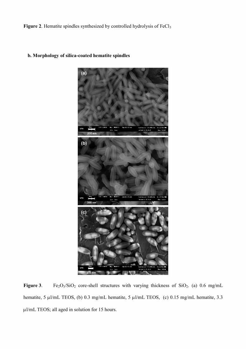
Figure 2. Hematite spindles synthesized by controlled hydrolysis of FeCl3
b. Morphology of silica-coated hematite spindles
Figure 3. Fe2O3/SiO2 core-shell structures with varying thickness of SiO2. (a) 0.6 mg/mL
hematite, 5 l/mL TEOS, (b) 0.3 mg/mL hematite, 5 l/mL TEOS, (c) 0.15 mg/mL hematite, 3.3
l/mL TEOS; all aged in solution for 15 hours.
The thickness of the silica coating (Figure 3) was controlled by the ratio of the particles and
TEOS in the growth solution. In this study, the thickness of silica was controlled within the range
from 20 ~ 60 nm. The spindle shape of the hematite particles was preserved in the process, but the
surface become much smoother, and the aspect ratio of the particles was decreased.
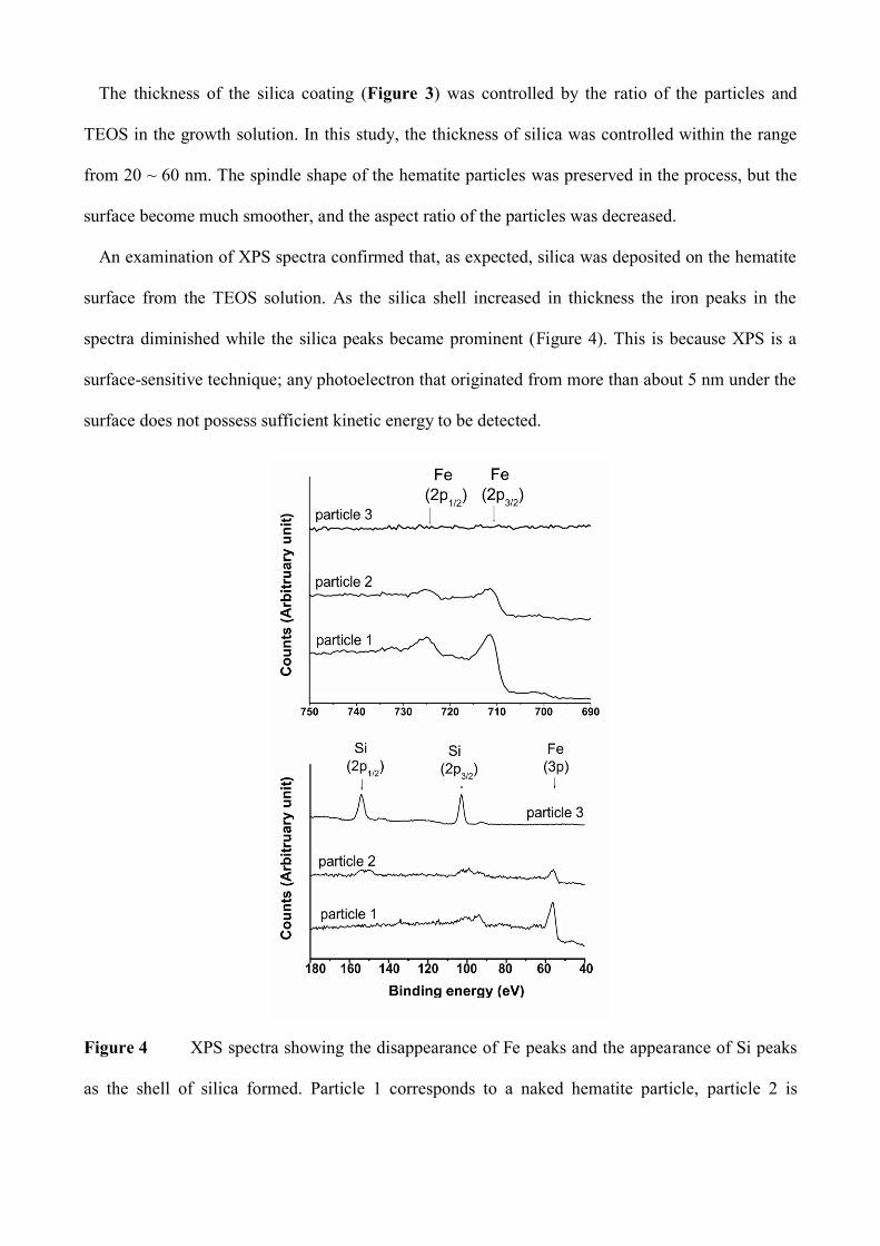
An examination of XPS spectra confirmed that, as expected, silica was deposited on the hematite
surface from the TEOS solution. As the silica shell increased in thickness the iron peaks in the
spectra diminished while the silica peaks became prominent (Figure 4). This is because XPS is a
surface-sensitive technique; any photoelectron that originated from more than about 5 nm under the
surface does not possess sufficient kinetic energy to be detected.
Figure 4 XPS spectra showing the disappearance of Fe peaks and the appearance of Si peaks
as the shell of silica formed. Particle 1 corresponds to a naked hematite particle, particle 2 is
hematite coated with a thin coating of SiO2 (Figure 3(a)), and particle 3 is hematite coated with a
thick layer of SiO2 (Figure 3(c)).
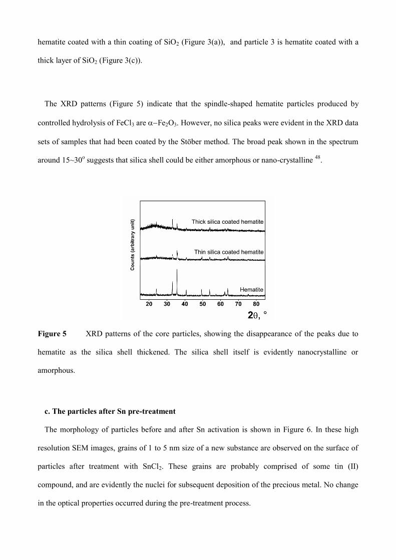
The XRD patterns (Figure 5) indicate that the spindle-shaped hematite particles produced by
controlled hydrolysis of FeCl3 are Fe2O3. However, no silica peaks were evident in the XRD data
sets of samples that had been coated by the Stöber method. The broad peak shown in the spectrum
around 15~30o suggests that silica shell could be either amorphous or nano-crystalline
48.
Figure 5 XRD patterns of the core particles, showing the disappearance of the peaks due to
hematite as the silica shell thickened. The silica shell itself is evidently nanocrystalline or
amorphous.
c. The particles after Sn pre-treatment
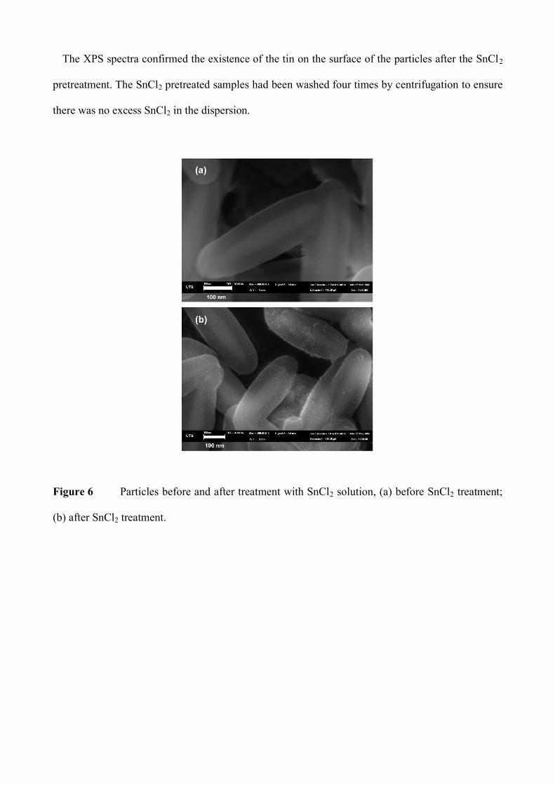
The morphology of particles before and after Sn activation is shown in Figure 6. In these high
resolution SEM images, grains of 1 to 5 nm size of a new substance are observed on the surface of
particles after treatment with SnCl2. These grains are probably comprised of some tin (II)
compound, and are evidently the nuclei for subsequent deposition of the precious metal. No change
in the optical properties occurred during the pre-treatment process.
The XPS spectra confirmed the existence of the tin on the surface of the particles after the SnCl2
pretreatment. The SnCl2 pretreated samples had been washed four times by centrifugation to ensure
there was no excess SnCl2 in the dispersion.
Figure 6 Particles before and after treatment with SnCl2 solution, (a) before SnCl2 treatment;
(b) after SnCl2 treatment.
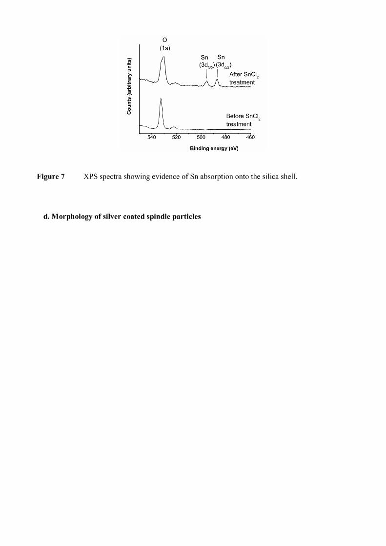
Figure 7 XPS spectra showing evidence of Sn absorption onto the silica shell.
d. Morphology of silver coated spindle particles
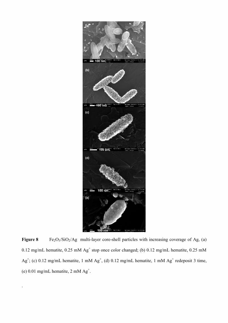
Figure 8 Fe2O3/SiO2/Ag multi-layer core-shell particles with increasing coverage of Ag, (a)
0.12 mg/mL hematite, 0.25 mM Ag+ stop once color changed; (b) 0.12 mg/mL hematite, 0.25 mM
Ag+; (c) 0.12 mg/mL hematite, 1 mM Ag
+, (d) 0.12 mg/mL hematite, 1 mM Ag
+ redeposit 3 time,
(e) 0.01 mg/mL hematite, 2 mM Ag+.
.
The morphologies of Fe2O3/SiO2/Ag core-shell structures prepared with varying proportions of
reactants are shown in Figure 8. At low concentrations of Ag, isolated particles of Ag ranging
between 2 and 5 nm in size were deposited on the SiO2 surface coating (Figure 8a.). The Ag
particles for this sample show a narrow size distribution. When a larger amount of Ag was
available, nucleation continued for some time, with the particles that formed first growing to a
larger size. This inevitably resulted in a wide distribution of particle sizes (Figure 8b (b, c)), with
the central tendency being in the 10 to 20 nm range. However, the silica surface was not yet fully
covered by Ag. Further increase of Ag concentration resulted in the formation of a contiguous
coverage of Ag nanoparticles (Figure 8 d.), which were granular and un-coalesced in nature.
Nevertheless, the packing density of the Ag particles in this stage is so high that the surface of the
Fe2O3/SiO2 composite particle is fully covered. The size of these particles also increased somewhat
from 10 to 20 nm, to 15 to 30 nm. Finally, a continuous shell structure was observed in solutions of
very high Ag content. In this case, the coating of Ag deposited on the SiO2 surface appeared
uniform and relatively smooth. (Figure 8 e). There were two practical problems associated with the
production of the last type of particle: firstly, yield of the composite particles was low due to very
low concentration of hematite particles in the solution, and secondly the solution was unstable and
susceptible to auto-catalytic self-decomposition. When this occurred free Ag was also precipitated,
which rendered isolation of the particles difficult.
Examination of the images revealed that the size of the particles increased with the silver
concentration. At first sight this might be unexpected for a nucleation-and-growth reaction. It is
generally observed in such reactions that greater driving force and faster reaction rate tends to
produce more nuclei and a smaller final particle size, which would also be the preferred situation
when attempting to produce a thin, continuous coating of Ag. In the present instance, however, the
large specific surface area (of the order of 10 m2/g )
49 has the consequence that nucleation sites are
abundant. Therefore, the rate of nucleation is not a restriction. It is likely that Ag nuclei are formed
rapidly once the particles are contacted with the Ag-containing solution. The particle size effect is
therefore likely to be due simply to depletion of the available Ag+, with larger particles growing
where more Ag+ was available.
Effect of tin sensitization
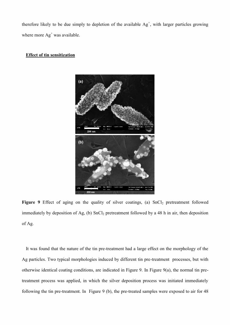
Figure 9 Effect of aging on the quality of silver coatings, (a) SnCl2 pretreatment followed
immediately by deposition of Ag, (b) SnCl2 pretreatment followed by a 48 h in air, then deposition
of Ag.
It was found that the nature of the tin pre-treatment had a large effect on the morphology of the
Ag particles. Two typical morphologies induced by different tin pre-treatment processes, but with
otherwise identical coating conditions, are indicated in Figure 9. In Figure 9(a), the normal tin pre-
treatment process was applied, in which the silver deposition process was initiated immediately
following the tin pre-treatment. In Figure 9 (b), the pre-treated samples were exposed to air for 48
hours, after which the same Ag deposition process was applied. It is clear that a prompt deposition
of Ag resulted in a smaller particle size and narrower size distribution. This is essential to make a
thin, prolate silver shell structure. A delay in Ag deposition, however, led to precipitation of fewer
and larger Ag nanoparticles.
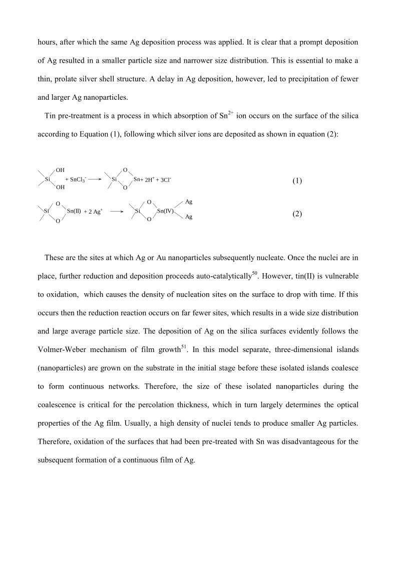
Tin pre-treatment is a process in which absorption of Sn2+
ion occurs on the surface of the silica
according to Equation (1), following which silver ions are deposited as shown in equation (2):
+ SnCl3-
+ 2H+ + 3Cl-
OH
OH
Si
O
O
SnSi (1)
+ 2 Ag+ Si
O
O
Sn(IV)
Ag
AgSi
O
O
Sn(II) (2)
These are the sites at which Ag or Au nanoparticles subsequently nucleate. Once the nuclei are in
place, further reduction and deposition proceeds auto-catalytically50
. However, tin(II) is vulnerable
to oxidation, which causes the density of nucleation sites on the surface to drop with time. If this
occurs then the reduction reaction occurs on far fewer sites, which results in a wide size distribution
and large average particle size. The deposition of Ag on the silica surfaces evidently follows the
Volmer-Weber mechanism of film growth51
. In this model separate, three-dimensional islands
(nanoparticles) are grown on the substrate in the initial stage before these isolated islands coalesce
to form continuous networks. Therefore, the size of these isolated nanoparticles during the
coalescence is critical for the percolation thickness, which in turn largely determines the optical
properties of the Ag film. Usually, a high density of nuclei tends to produce smaller Ag particles.
Therefore, oxidation of the surfaces that had been pre-treated with Sn was disadvantageous for the
subsequent formation of a continuous film of Ag.
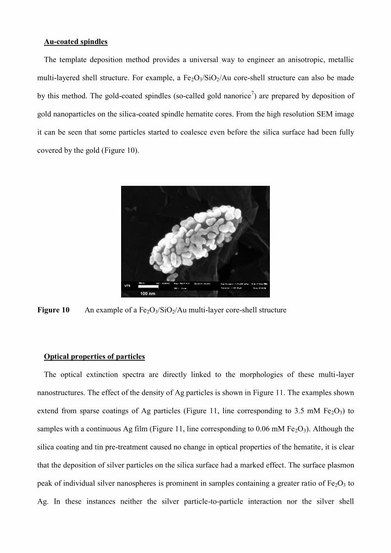
Au-coated spindles
The template deposition method provides a universal way to engineer an anisotropic, metallic
multi-layered shell structure. For example, a Fe2O3/SiO2/Au core-shell structure can also be made
by this method. The gold-coated spindles (so-called gold nanorice7) are prepared by deposition of
gold nanoparticles on the silica-coated spindle hematite cores. From the high resolution SEM image
it can be seen that some particles started to coalesce even before the silica surface had been fully
covered by the gold (Figure 10).
Figure 10 An example of a Fe2O3/SiO2/Au multi-layer core-shell structure
Optical properties of particles
The optical extinction spectra are directly linked to the morphologies of these multi-layer
nanostructures. The effect of the density of Ag particles is shown in Figure 11. The examples shown
extend from sparse coatings of Ag particles (Figure 11, line corresponding to 3.5 mM Fe2O3) to
samples with a continuous Ag film (Figure 11, line corresponding to 0.06 mM Fe2O3). Although the
silica coating and tin pre-treatment caused no change in optical properties of the hematite, it is clear
that the deposition of silver particles on the silica surface had a marked effect. The surface plasmon
peak of individual silver nanospheres is prominent in samples containing a greater ratio of Fe2O3 to
Ag. In these instances neither the silver particle-to-particle interaction nor the silver shell
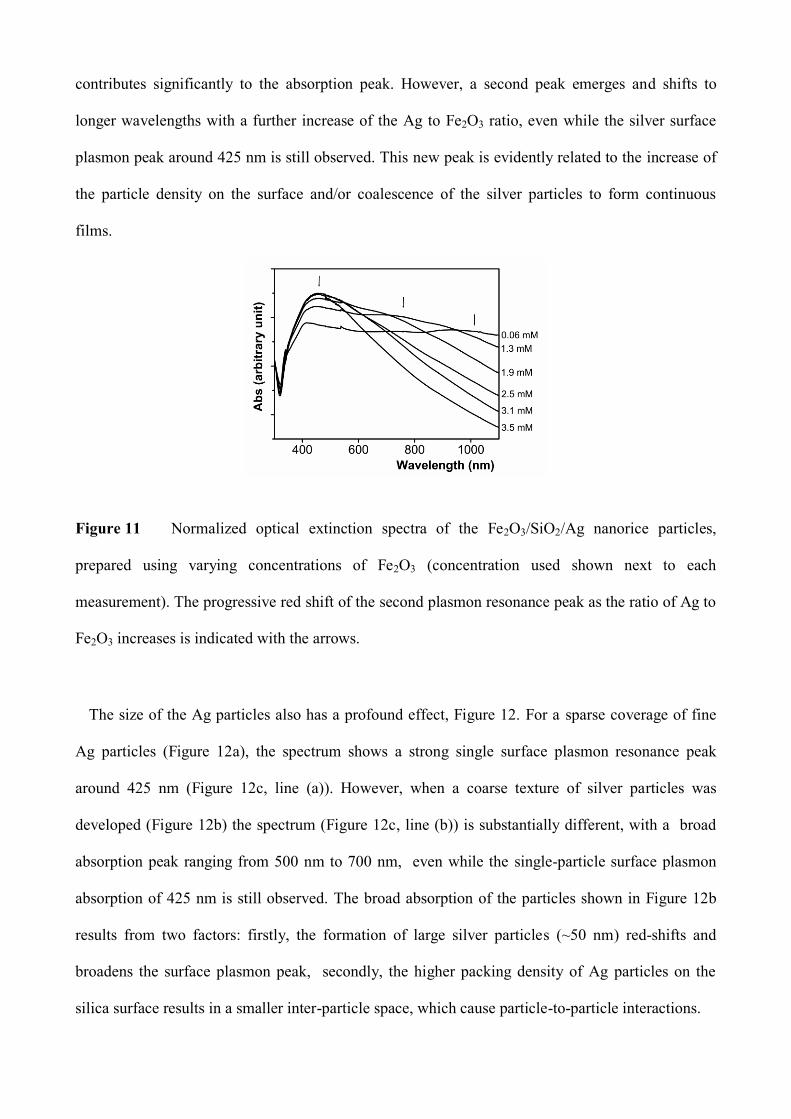
contributes significantly to the absorption peak. However, a second peak emerges and shifts to
longer wavelengths with a further increase of the Ag to Fe2O3 ratio, even while the silver surface
plasmon peak around 425 nm is still observed. This new peak is evidently related to the increase of
the particle density on the surface and/or coalescence of the silver particles to form continuous
films.
Figure 11 Normalized optical extinction spectra of the Fe2O3/SiO2/Ag nanorice particles,
prepared using varying concentrations of Fe2O3 (concentration used shown next to each
measurement). The progressive red shift of the second plasmon resonance peak as the ratio of Ag to
Fe2O3 increases is indicated with the arrows.
The size of the Ag particles also has a profound effect, Figure 12. For a sparse coverage of fine
Ag particles (Figure 12a), the spectrum shows a strong single surface plasmon resonance peak
around 425 nm (Figure 12c, line (a)). However, when a coarse texture of silver particles was
developed (Figure 12b) the spectrum (Figure 12c, line (b)) is substantially different, with a broad
absorption peak ranging from 500 nm to 700 nm, even while the single-particle surface plasmon
absorption of 425 nm is still observed. The broad absorption of the particles shown in Figure 12b
results from two factors: firstly, the formation of large silver particles (~50 nm) red-shifts and
broadens the surface plasmon peak, secondly, the higher packing density of Ag particles on the
silica surface results in a smaller inter-particle space, which cause particle-to-particle interactions.
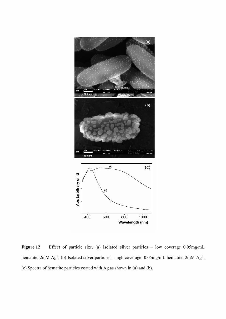
Figure 12 Effect of particle size. (a) Isolated silver particles – low coverage 0.05mg/mL
hematite, 2mM Ag+; (b) Isolated silver particles – high coverage 0.05mg/mL hematite, 2mM Ag
+.
(c) Spectra of hematite particles coated with Ag as shown in (a) and (b).
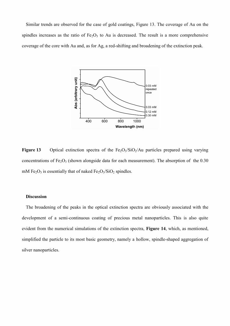
Similar trends are observed for the case of gold coatings, Figure 13. The coverage of Au on the
spindles increases as the ratio of Fe2O3 to Au is decreased. The result is a more comprehensive
coverage of the core with Au and, as for Ag, a red-shifting and broadening of the extinction peak.
Figure 13 Optical extinction spectra of the Fe2O3/SiO2/Au particles prepared using varying
concentrations of Fe2O3 (shown alongside data for each measurement). The absorption of the 0.30
mM Fe2O3 is essentially that of naked Fe2O3/SiO2 spindles.
Discussion
The broadening of the peaks in the optical extinction spectra are obviously associated with the
development of a semi-continuous coating of precious metal nanoparticles. This is also quite
evident from the numerical simulations of the extinction spectra, Figure 14, which, as mentioned,
simplified the particle to its most basic geometry, namely a hollow, spindle-shaped aggregation of
silver nanoparticles.
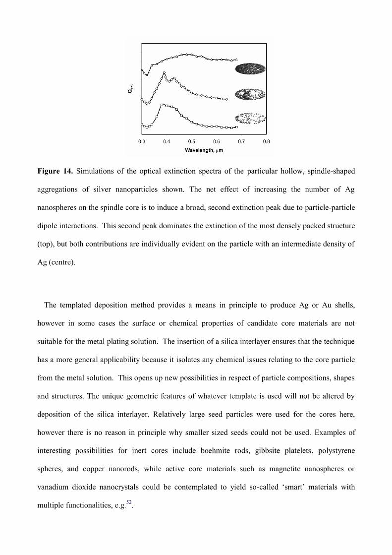
Figure 14. Simulations of the optical extinction spectra of the particular hollow, spindle-shaped
aggregations of silver nanoparticles shown. The net effect of increasing the number of Ag
nanospheres on the spindle core is to induce a broad, second extinction peak due to particle-particle
dipole interactions. This second peak dominates the extinction of the most densely packed structure
(top), but both contributions are individually evident on the particle with an intermediate density of
Ag (centre).
The templated deposition method provides a means in principle to produce Ag or Au shells,
however in some cases the surface or chemical properties of candidate core materials are not
suitable for the metal plating solution. The insertion of a silica interlayer ensures that the technique
has a more general applicability because it isolates any chemical issues relating to the core particle
from the metal solution. This opens up new possibilities in respect of particle compositions, shapes
and structures. The unique geometric features of whatever template is used will not be altered by
deposition of the silica interlayer. Relatively large seed particles were used for the cores here,
however there is no reason in principle why smaller sized seeds could not be used. Examples of
interesting possibilities for inert cores include boehmite rods, gibbsite platelets, polystyrene
spheres, and copper nanorods, while active core materials such as magnetite nanospheres or
vanadium dioxide nanocrystals could be contemplated to yield so-called ‘smart’ materials with
multiple functionalities, e.g.52
.
Conclusion
An improved method for producing anisotropic Ag or Au-coated, spindle-shaped particles is
demonstrated in this study. The core of the particle is a hematite spindle that is then coated with a
layer of silica. The silica in turn is rendered suitable for the attachment of Ag or Au nanoparticles
by an activating treatment with SnCl2. The resulting core-shell structures manifested a plasmonic
resonance that could be varied from a single broad peak at ~450 nm through to a broad extinction
band spread over 450 to 1000 nm. The details of the optical properties were largely controlled by
the morphology and distribution of the attached precious metal nanoparticles which were controlled
by the relative proportions of the reactants and the reaction conditions. Lower concentrations of
silver were preferable to obtain for thinner, more continuous metallic films, while a coarse texture
of the film was developed from more concentrated silver solutions. The silica shells produced by
the Stöber method were smooth and continuous, and they preserved the geometric features of the
core particle, thereby greatly facilitating the construction of multi-layer, core-shell structures.
Acknowledgement
This work was supported by Australian Research Council grant DP0666689.
References
(1) Murphy, C. J.; Sau, T. K.; Gole, A. M.; Orendorff, C. J.; Gao, J.; Gou, L.; Hunyadi, S. E.;
Li, T. J. Phys. Chem. B 2005, 109, 13857-13870.
(2) Perez-Juste, J.; Pastoriza-Santos, I.; Liz-Marzan, L. M.; Mulvaney, P. Coordin. Chem. Rev.
2005, 249, 1870-1901.
(3) Oldenburg, S. J.; Jackson, J. B.; Westcott, S. L.; Halas, N. J. Appl. Phys. Lett. 1999, 75,
2897-2899.
(4) Liu, J.; Maaroof, A. I.; Wieczorek, L.; Cortie, M. B. Adv. Mater. 2005, 17, 1276 - 1281.
(5) Charnay, C.; Lee, A.; Man, S.; Moran, C. E.; Radloff, C.; Bradley, R. K.; Halas, N. J. J.
Phys. Chem. B 2003, 107, 7327-7333.
(6) Kelly, K. L.; Coronado, E.; Zhao, L. L.; Schatz, G. C. J. Phys. Chem. B 2003, 107, 668-677.
(7) Wang, H.; Brandl, D. W.; Le, F.; Nordlander, P.; Halas, N. J. Nano Lett. 2006, 6, 827-832.
(8) Oldenburg, S. J.; Averitt, R. D.; Westcott, S. L.; Halas, N. J. Chem. Phys. Lett. 1998, 288,
243-247.
(9) Halas, N. MRS Bull. 2005, 30, 362-367.
(10) Oldenburg, S. J.; Averitt, R. D.; Halas, N. J. Metal nanoshells. US Patent 6,344,272, 2002.
(11) Loo, C.; Lin, A.; Hirsch, L.; Lee, M. H.; Barton, J.; Halas, N.; West, J.; Drezek, R. Technol
Cancer Res T 2004, 3, 33-40.
(12) Hirsch, L. R.; Stafford, R. J.; Bankson, J. A.; Sershen, S. R.; Rivera, B.; Price, R. E.; Hazle,
J. D.; Halas, N. J.; West, J. L. Proc. Nat. Acad. Sci. USA 2003, 100, 13549-13554.
(13) O'Neal, D. P.; Hirsch, L. R.; Halas, N. J.; Payne, J. D.; West, J. L. Cancer Lett. 2004, 209,
171-176.
(14) Hirsch, L.; Gobin, A.; Lowery, A.; F, T.; Drezek, R.; Halas, N.; JL, W. Annals of
Biomedical Engineering 2006, 34, 15-22.
(15) Pissuwan, D.; Valenzuela, S.; Cortie, M. B. Trends Biotechnol. 2006, 24, 62-67.
(16) Xu, X.; Cortie, M. B. Adv. Func. Mater. 2006, 16, 2170-2176.
(17) Prescott, S. W.; Mulvaney, P. J. Appl. Phys. 2006, 99, 123504.
(18) Xu, X.; Gibbons, T.; Cortie, M. B. Gold Bull. 2006, 39, 156-165.
(19) Aslan, K.; Leonenko, Z.; Lakowicz, J. R.; Geddes, C. D. J. Phys. Chem. B 2005, 109, 3157-
3162.
(20) Orendorff, C. J.; Gearheart, L. A.; Jana, N. R.; Murphy, C. J. Phys. Chem. Chem. Phys.
2006, 8, 165-170.
(21) El-Sayed, I. H.; Huang, X.; El-Sayed, M. A. Cancer Lett. 2006, 239, 129-135.
(22) Pissuwan, D.; Valenzuela, S. M.; Killingsworth, M. C.; Xu, X.; Cortie, M. B. J.
Nanoparticle Res. 2007, in press, DOI 10.1007/s11051-11007-19212-z.
(23) Jana, N. R.; Gearheart, L. A.; Murphy, C. J. Chem. Mater. 2001, 13, 2313-2322.
(24) Jana, N. R.; Gearheart, L. A.; Murphy, C. J. Adv. Mater. 2001, 13, 1389-1393.
(25) Nikoobakht, B.; El-Sayed, M. A. Chem. Mater. 2003, 15, 1957-1962.
(26) Pastoriza-Santos, I.; Pérez-Juste, J.; Liz-Marzán, L. M. Chem. Mater. 2006, 18, 2465-2468.
(27) Gole, A.; Murphy, C. J. Chem. Mater. 2005, 17, 1325-1330.
(28) Peceros, K. E.; Xu, X.; Bulcock, S. R.; Cortie, M. B. J. Phys. Chem. B 2005, 109, 21516-
21520.
(29) Quinten, M.; Kreibig, U. Surf. Sci. 1986, 172, 557-577.
(30) Ung, T.; Liz-Marzan, L. M.; Mulvaney, P. Colloids and Surfaces A: Physicochemical and
Engineering Aspects 2002, 202, 119-126.
(31) Xu, X.; Stevens, M.; Cortie, M. B. Chem. Mater. 2004, 16, 2259-2266.
(32) Wiley, B. J.; Chen, Y.; McLellan, J.; Xiong, Y.; Li, Z.-Y.; Ginger, D.; Xia, Y. Nano Lett.
2007, 7, 1032-1036.
(33) Wang, L.; Luo, J.; Fan, Q.; Suzuki, M.; Suzuki, I. S.; Engelhard, M. H.; Lin, Y.; Kim, N.;
Wang, J. Q.; Zhong, C.-J. J. Phys. Chem. B 2005, 109, 21593-21601.
(34) Stöber, W.; Fink, A.; Bohn, E. J. Colloid Interface Sci. 1968, 26, 62-69.
(35) Liz-Marzan, L. M.; Giersig, M.; Mulvaney, P. Langmuir 1996, 12, 4329-4335.
(36) Mulvaney, P. C.; Liz-Marzan, L. M. Stabilized particles and methods of preparation and use
therof. International Patent WO99/21934, 1999.
(37) Ung, T.; Liz-Marzan, L. M.; Mulvaney, P. J. Phys. Chem. B 2001, 105, 3441-3452.
(38) Graf, C.; Vossen, D. L. J.; Imhof, A.; Blaadere, A. V. Langmuir 2003, 19, 6693-6700.
(39) Zhou, C.; Peng, Z.; Jian-hui, Z.; Zhen-lin, W.; Wei-yi, Z.; Nai-ben, M. Chin. Phys. Lett.
2003, 20, 1369-1371.
(40) Miller, R. G.; Cavitt, R. L. Novel method for the rapid depositon of gold films onto non-
metallic substrates at ambient temperatures,. United States Patent 4,005,229, 1977.
(41) Laroche, P.; Boulanger, P.; Dauby, C. Silver coated mirror. United States Patent
6565217B2, 2003.
(42) Ohmori, M.; Matijevic, E. J. Colloid Interface Sci. 1992, 150, 594-598.
(43) Ohmori, M.; Matijevic, E. J. Colloid Interface Sci. 1993, 160, 288-292.
(44) Lim, Y. T.; Park, O. O.; Jung, H.-T. J. Colloid Interface Sci. 2003, 263, 449-453.
(45) Draine, B. T.; Flatau, P. J. User Guide for the Discrete Dipole Approximation Code
DDSCAT 6.1, 2004.
(46) Draine, B. T.; Flatau, P. J. J. Opt. Soc. Am. A 1994, 11, 1491-1499.
(47) Kooij, E. S.; Poelsema, B. Phys. Chem. Chem. Phys. 2006, 8, 3349–3357.
(48) Yoshida, H.; Kimura, K.; Inaki, Y.; Hattori, T. Chem. Commun. 1997, 129-130.
(49) Alexander, G. B.; Nadkarni, R. M. Method for electroless plating of ultrafine or colloidal
particles and products produced thereby. United States Patent 4,944,985 US, 1990.
(50) Mallory, G. O.; Hajdu, J. B. Electroless Plating: Fundamentals and Applications; American
Electroplaters and Surface Finishers Society: Orlando, Florida, 1990.
(51) Kaiser, N.; Pulker, H. K. Optical Interference Coatings; Springer: Berlin, 2003.

(52) Cortie, M. B.; Dowd, A.; Harris, N.; Ford, M. J. Phys. Rev. B 2007, 75, 113405.