Embed Size (px)
Citation preview

Contents
• Reciprocal Lattice • Ewald Sphere • Stereographic projections • Diffraction methods • Reciprocal Space Mapping and Rocking curve analysis
References: B.D. Cullity, Elements of X-ray Diffraction Paul Fewster, X-ray scattering in semiconductors, Imperial College Press
Reciprocal Lattice
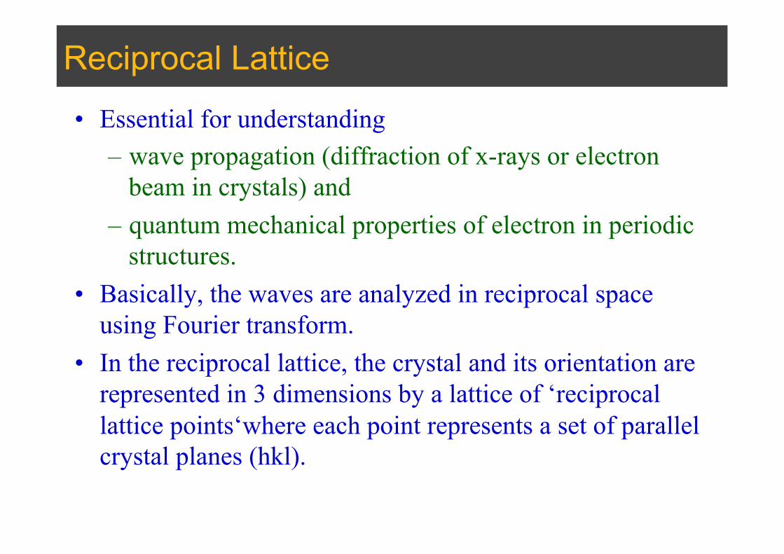
• Essential for understanding – wave propagation (diffraction of x-rays or electron
beam in crystals) and – quantum mechanical properties of electron in periodic
structures. • Basically, the waves are analyzed in reciprocal space
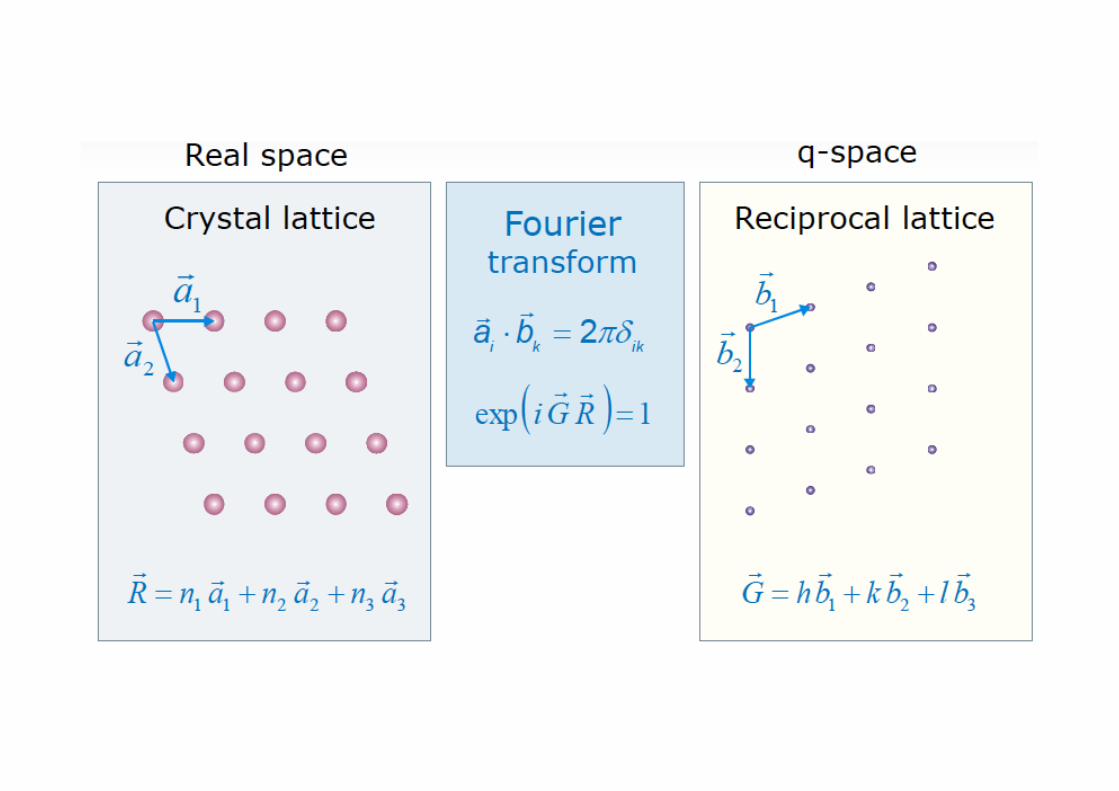
using Fourier transform. • In the reciprocal lattice, the crystal and its orientation are
represented in 3 dimensions by a lattice of ‘reciprocal lattice points‘where each point represents a set of parallel crystal planes (hkl).
Reciprocal Lattice
• Every periodic structure has two lattices associated with it.
• The first is the real space lattice, and this describes the periodic structure.
• The second is the reciprocal lattice, and this determines how the periodic structure interacts with waves

Periodic Functions
• Any periodic function can be expressed in terms of its periodic Fourier components (harmonics).
• Example of periodic potential
– where Uk is the coefficient of the potential, and r is a real position vector
– However only values of K are allowed which are reciprocal lattice vectors, G.
U (r) = Uk exp(i2πK.r)k∑
Proof
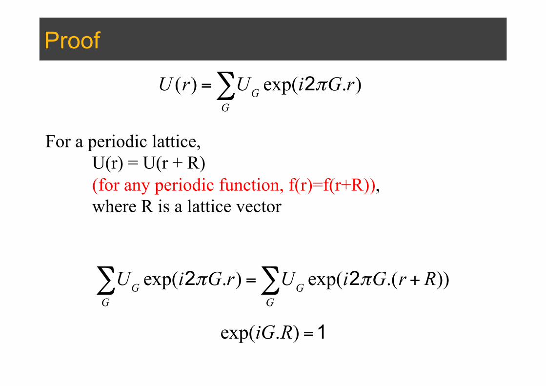
U (r) = UG exp(i2πG.r)G∑
For a periodic lattice, U(r) = U(r + R) (for any periodic function, f(r)=f(r+R)), where R is a lattice vector
UG exp(i2πG.r)G∑ = UG exp(i2πG.(r + R))
G∑
exp(iG.R) =1
Definitions
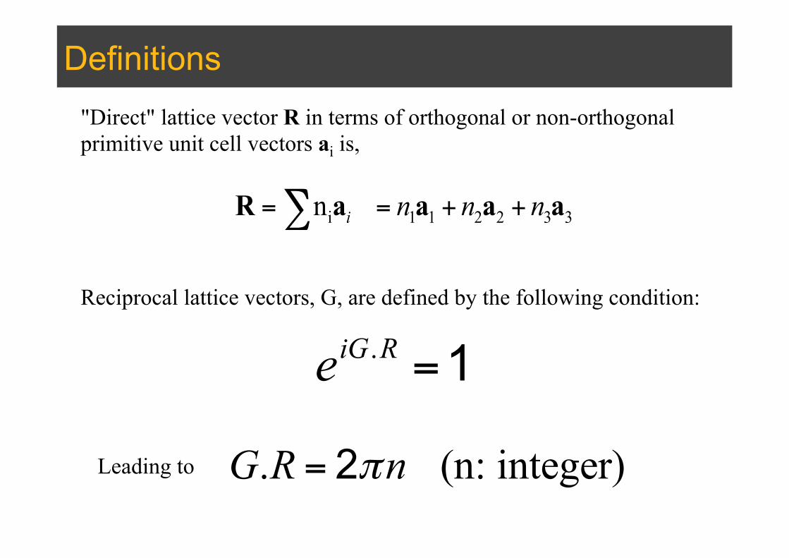
i 1 1 2 2 3 3n i n n n= = + +∑R a a a a
Reciprocal lattice vectors, G, are defined by the following condition:
eiG.R =1
"Direct" lattice vector R in terms of orthogonal or non-orthogonal primitive unit cell vectors ai is,
G.R = 2πn (n: integer)Leading to
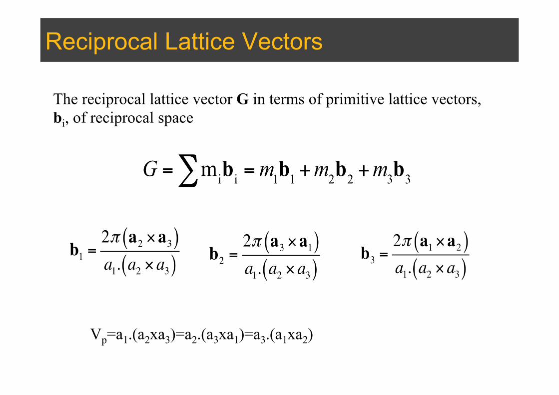
Reciprocal Lattice Vectors
G = mibi∑ =m1b1 +m2b2 +m3b3
b1 =2π a2 ×a3( )a1. a2 × a3( ) b2 =
2π a3 ×a1( )a1. a2 × a3( )
b3 =2π a1 ×a2( )a1. a2 × a3( )
Vp=a1.(a2xa3)=a2.(a3xa1)=a3.(a1xa2)
The reciprocal lattice vector G in terms of primitive lattice vectors, bi, of reciprocal space
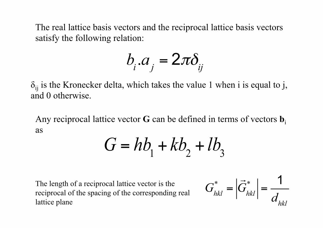
The real lattice basis vectors and the reciprocal lattice basis vectors satisfy the following relation:
bi .a j = 2πδijδij is the Kronecker delta, which takes the value 1 when i is equal to j, and 0 otherwise.
G = hb1 + kb2 + lb3
Any reciprocal lattice vector G can be defined in terms of vectors bi as
Ghkl* =
!Ghkl* =
1dhkl
The length of a reciprocal lattice vector is the reciprocal of the spacing of the corresponding real lattice plane
1a!
2a!
*b2!
*b1!
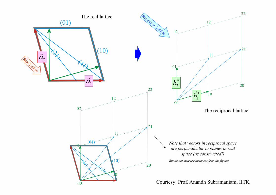
Note that vectors in reciprocal space are perpendicular to planes in real
space (as constructed!)
The real lattice
The reciprocal lattice
But do not measure distances from the figure!
Courtesy: Prof. Anandh Subramaniam, IITK

Real Crystal
Reciprocal Lattice
Reciprocal Crystal
Diffraction Pattern
Purely Geometrical Construction
Decoration of the lattice with Intensities
Ewald Sphere construction
Selection of some spots/intensities from the reciprocal crystal
Structure factor calculation
Real Lattice Decoration of the lattice with motif
Courtesy: Prof. Anandh Subramaniam, IITK
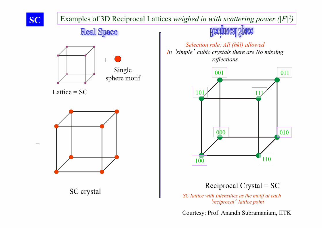
Examples of 3D Reciprocal Lattices weighed in with scattering power (|F|2)
000
100
111
001
101
011
010
110
SC
Lattice = SC
Reciprocal Crystal = SC
Selection rule: All (hkl) allowed In ‘simple’ cubic crystals there are No missing
reflections
SC lattice with Intensities as the motif at each ‘reciprocal’ lattice point
+ Single
sphere motif
=
SC crystal
Courtesy: Prof. Anandh Subramaniam, IITK
000
200
222
002
101
022
020
110
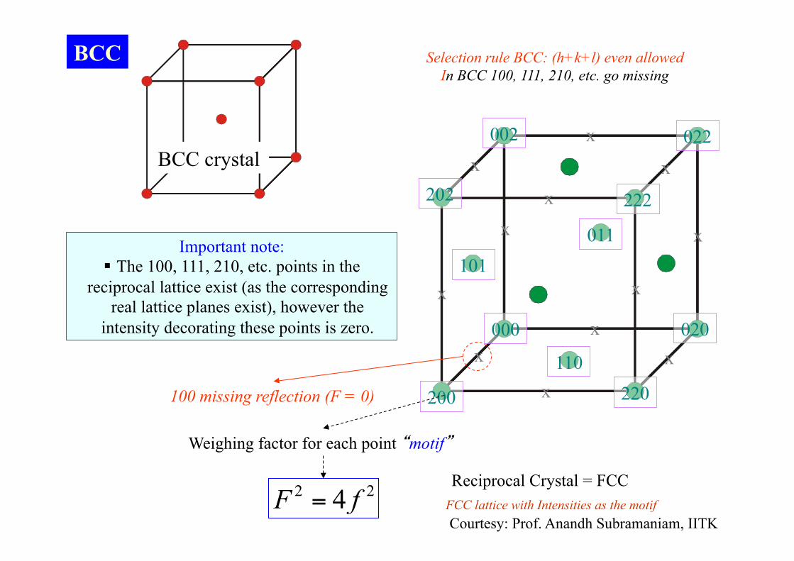
BCC
BCC crystal
Reciprocal Crystal = FCC
220
011
202
100 missing reflection (F = 0)
22 4 fF =
Weighing factor for each point “motif”
FCC lattice with Intensities as the motif
Selection rule BCC: (h+k+l) even allowed In BCC 100, 111, 210, etc. go missing
Important note: § The 100, 111, 210, etc. points in the
reciprocal lattice exist (as the corresponding real lattice planes exist), however the
intensity decorating these points is zero.
x
x
x
x
x
x
x
x
x
x
x
x
Courtesy: Prof. Anandh Subramaniam, IITK

000 200
222
002 022
020
FCC
Lattice = FCC
Reciprocal Crystal = BCC
220
111
202
100 missing reflection (F = 0) 110 missing reflection (F = 0)
22 16 fF =
Weighing factor for each point “motif”
BCC lattice with Intensities as the motif
Courtesy: Prof. Anandh Subramaniam, IITK

Bragg’s Law: Real Space
nλ=2d.sinθ n: Order of reflection d: Plane spacing = θ: Bragg Angle
2 2 2
ah k l+ +
Path difference must be integral multiples of the wavelength θin=θout
in out
2θ
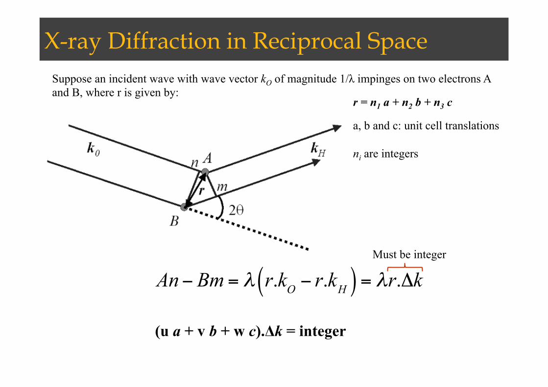
X-ray Diffraction in Reciprocal Space Suppose an incident wave with wave vector kO of magnitude 1/λ impinges on two electrons A and B, where r is given by:
r = n1 a + n2 b + n3 c
a, b and c: unit cell translations ni are integers
An− Bm = λ r.kO − r.kH( ) = λr.ΔkMust be integer
(u a + v b + w c).Δk = integer

Laue Equations
a.Δk = hb.Δk = kc.Δk = l
ah−bk
⎛
⎝⎜
⎞
⎠⎟.Δk = 0
bk−cl
⎛
⎝⎜
⎞
⎠⎟.Δk = 0
cl−ah
⎛
⎝⎜
⎞
⎠⎟.Δk = 0Δk =G
G must be perpendicular to plane (hkl)
dhkl =a.Gh |G |
=1|G |

Ewald Sphere Ewald Sphere
Paul Peter Ewald (1888-1985) Diffraction Condition
kH-ko=G
Plane hkl
| kH | sinθ+ | ko | sinθ =|G |1d=2sinθλ
For a diffracted beam with vector k to be present after diffraction from plane (hkl), the vector ko+Ghkl MUST lie on the Ewald sphere.
H
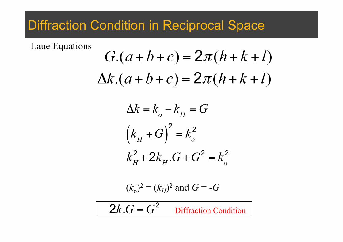
Diffraction Condition in Reciprocal Space Laue Equations
Δk = ko − kH =G
kH +G( )2= ko
2
kH2 +2kH .G +G
2 = ko2
(ko)2 = (kH)2 and G = -G
G.(a+b+ c) = 2π (h+ k + l)Δk.(a+b+ c) = 2π (h+ k + l)
Diffraction Condition 2k.G =G2
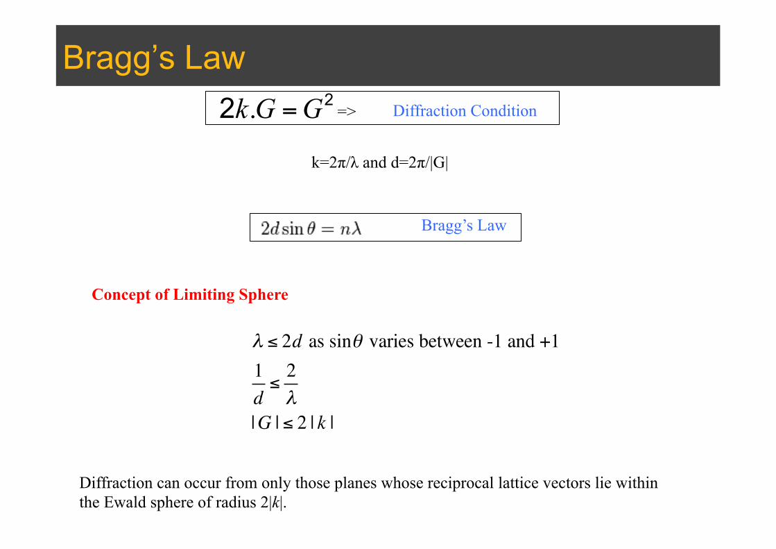
Bragg’s Law
k=2π/λ and d=2π/|G|
Bragg’s Law
λ ≤ 2d as sinθ varies between -1 and +11d≤
2λ
|G | ≤ 2 | k |
Concept of Limiting Sphere
Diffraction can occur from only those planes whose reciprocal lattice vectors lie within the Ewald sphere of radius 2|k|.
Diffraction Condition => 2k.G =G2
Example
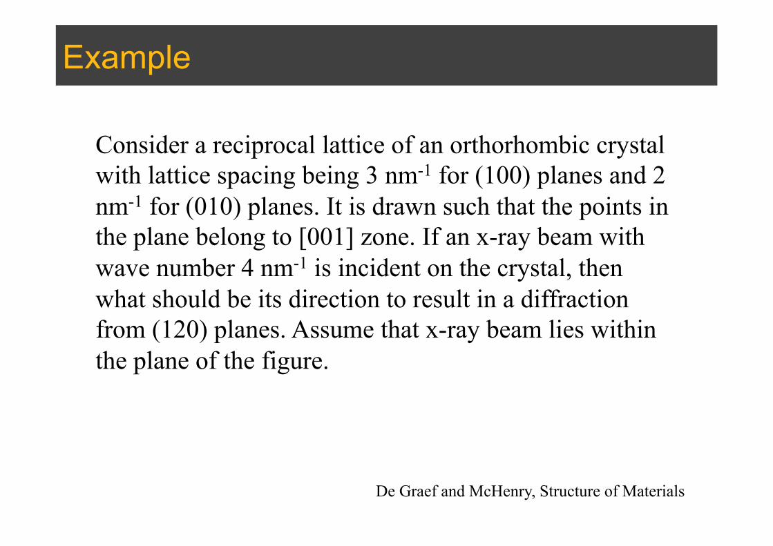
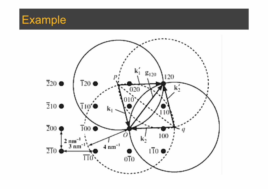
Consider a reciprocal lattice of an orthorhombic crystal with lattice spacing being 3 nm-1 for (100) planes and 2 nm-1 for (010) planes. It is drawn such that the points in the plane belong to [001] zone. If an x-ray beam with wave number 4 nm-1 is incident on the crystal, then what should be its direction to result in a diffraction from (120) planes. Assume that x-ray beam lies within the plane of the figure.
De Graef and McHenry, Structure of Materials
Example
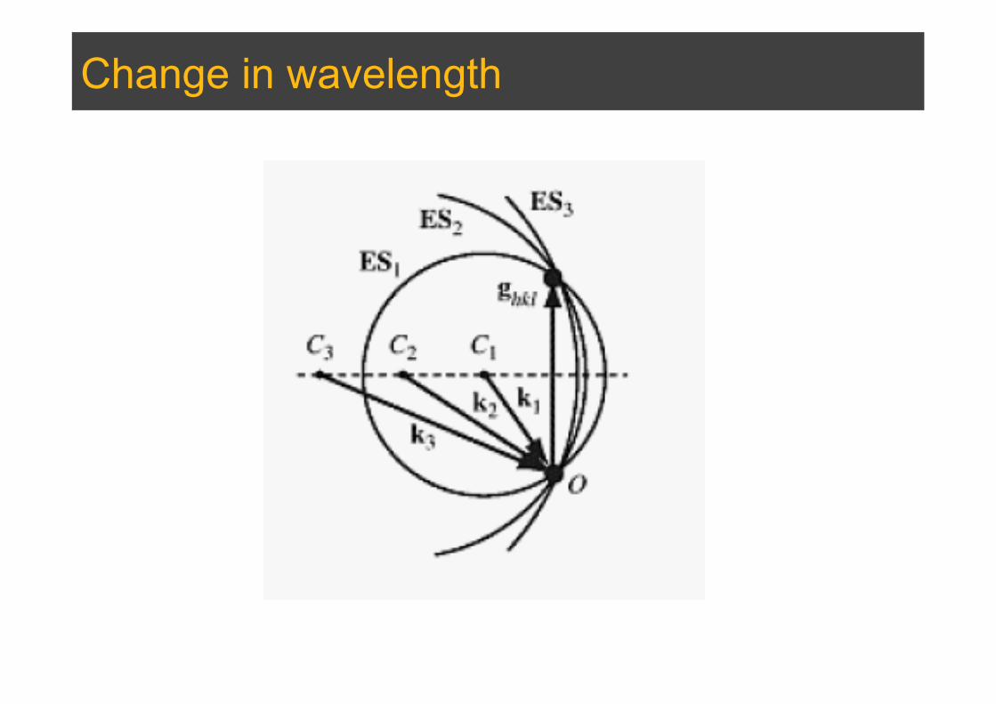
Change in wavelength

Stereographic projections
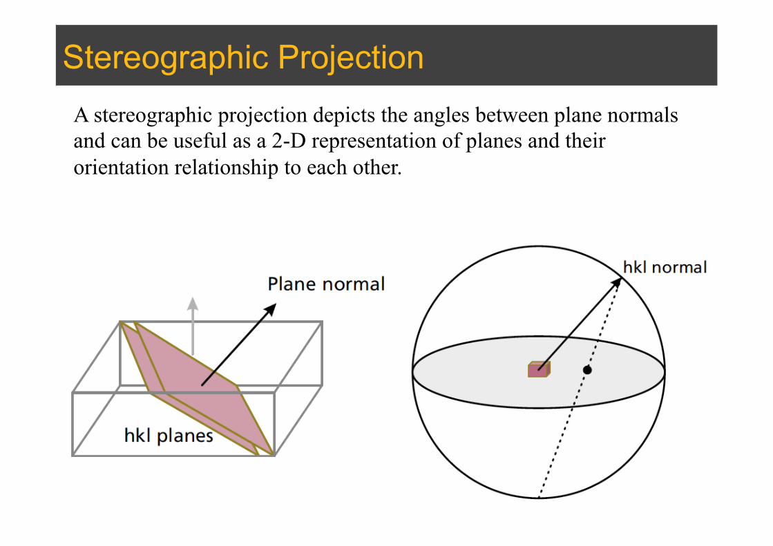
Stereographic Projection A stereographic projection depicts the angles between plane normals and can be useful as a 2-D representation of planes and their orientation relationship to each other.
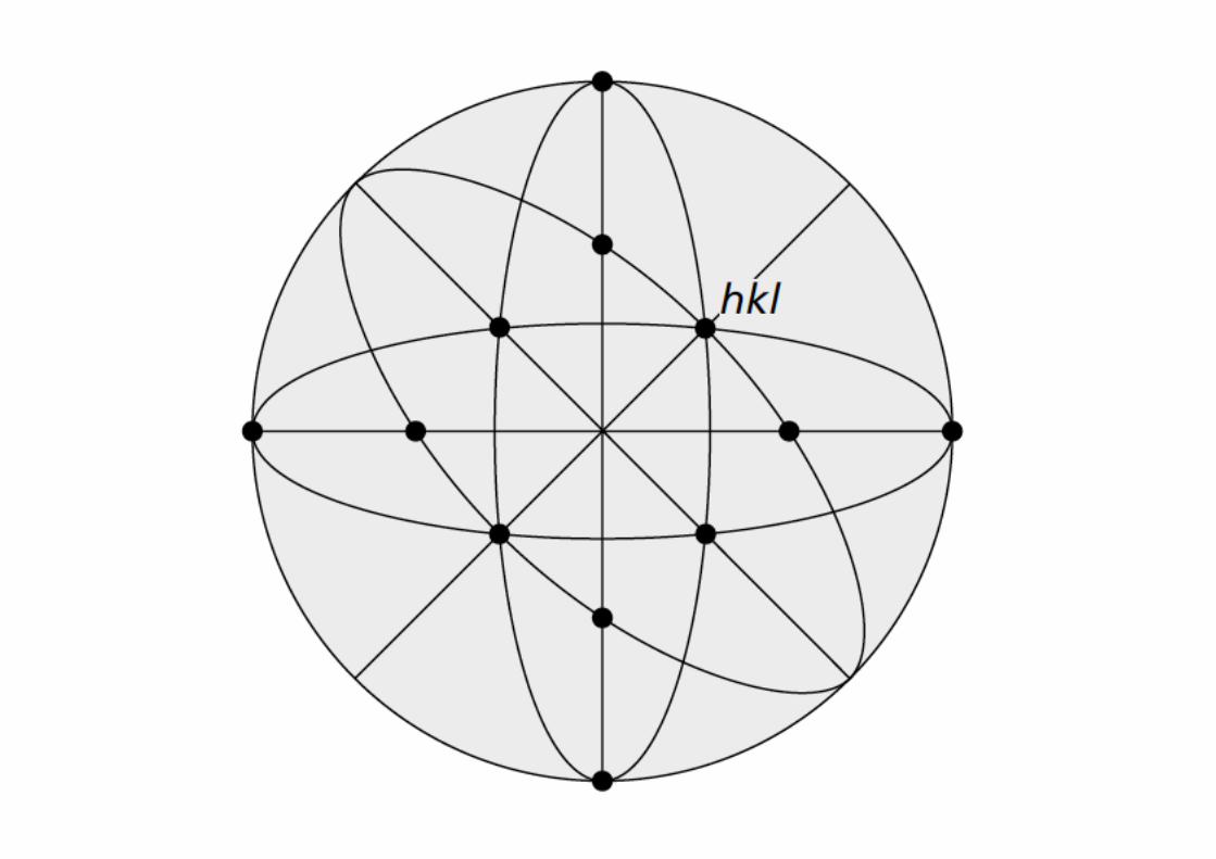

Poles
Ref: BD Cullity, Elements of X-ray Diffraction
Poles of a cubic crystal Angle between planes
Ref: BD Cullity, Elements of X-ray Diffraction
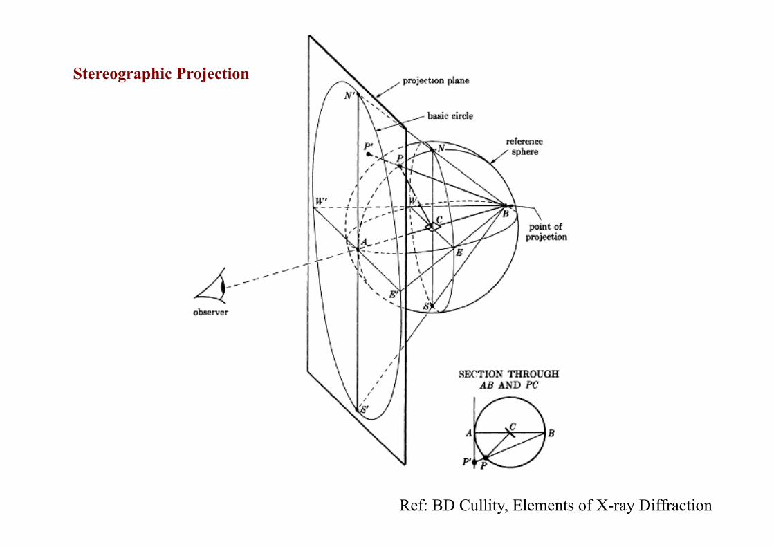
Stereographic Projection
Ref: BD Cullity, Elements of X-ray Diffraction
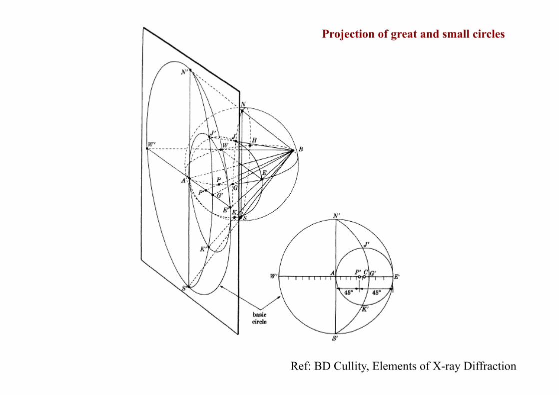
Projection of great and small circles

Ref: BD Cullity, Elements of X-ray Diffraction
Standard Cubic Projections
(001) (011)

(001) Projection of a cubic crystal
Ref: BD Cullity, Elements of X-ray Diffraction
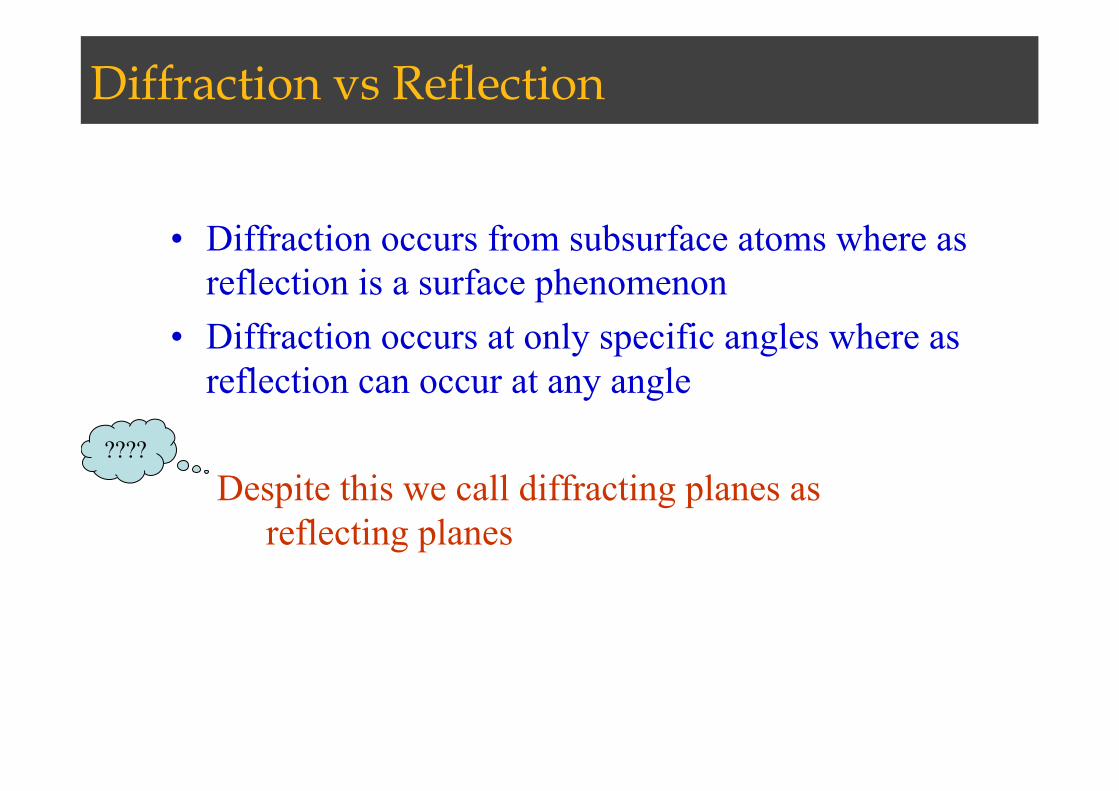
Diffraction vs Reflection
• Diffraction occurs from subsurface atoms where as reflection is a surface phenomenon
• Diffraction occurs at only specific angles where as reflection can occur at any angle
Despite this we call diffracting planes as reflecting planes
????
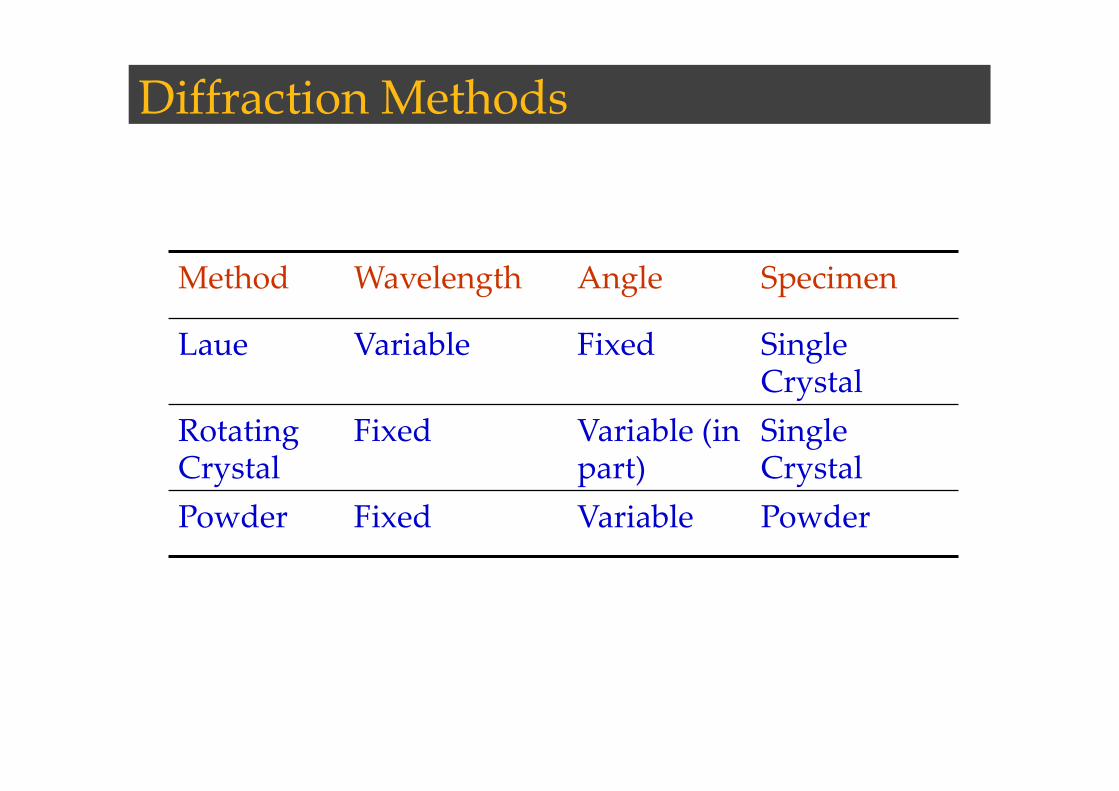
Diffraction Methods
Method Wavelength Angle Specimen
Laue Variable Fixed Single Crystal
Rotating Crystal
Fixed Variable (in part)
Single Crystal
Powder Fixed Variable Powder
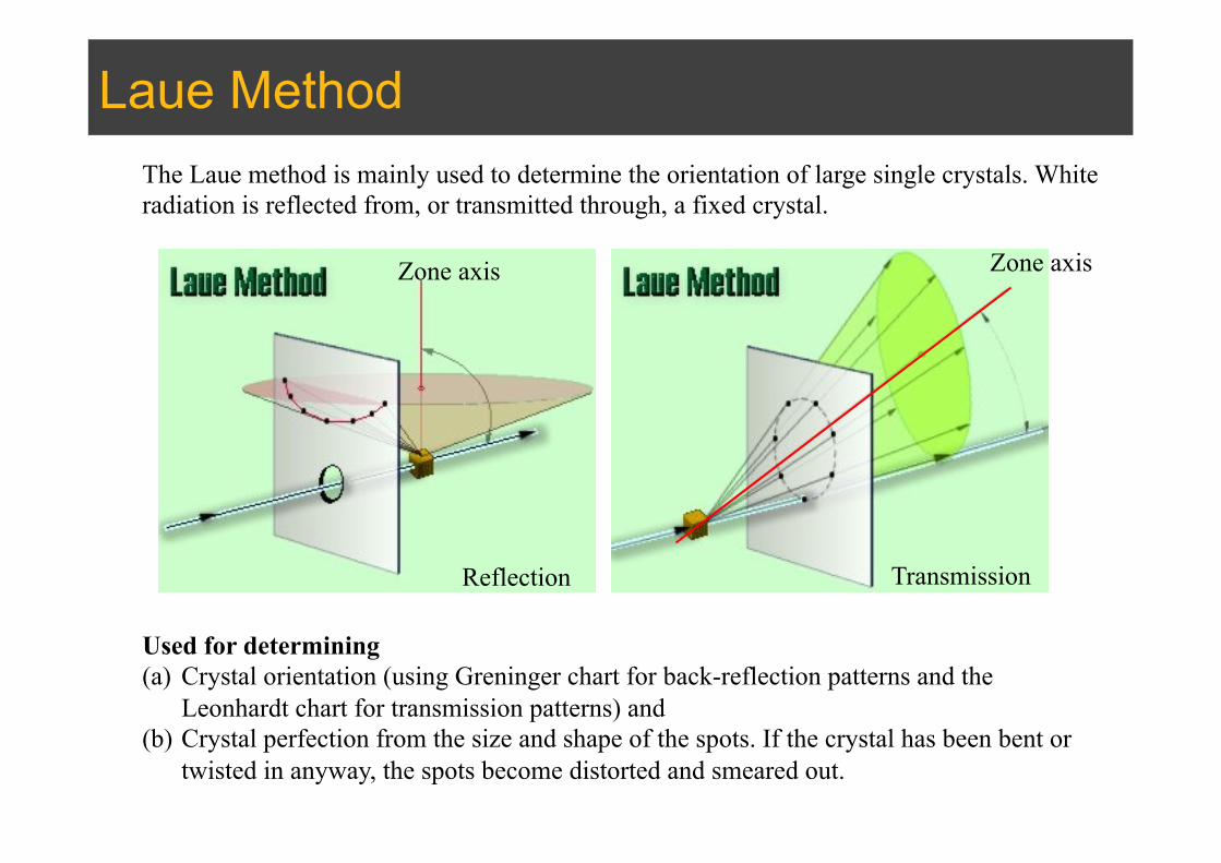
Laue Method The Laue method is mainly used to determine the orientation of large single crystals. White radiation is reflected from, or transmitted through, a fixed crystal.
Used for determining (a) Crystal orientation (using Greninger chart for back-reflection patterns and the
Leonhardt chart for transmission patterns) and (b) Crystal perfection from the size and shape of the spots. If the crystal has been bent or
twisted in anyway, the spots become distorted and smeared out.
Reflection Transmission
Zone axis Zone axis
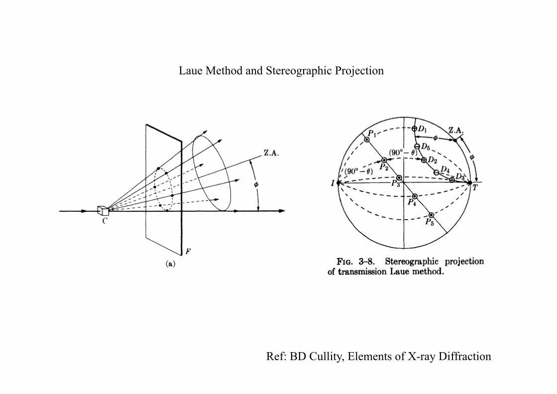
Ref: BD Cullity, Elements of X-ray Diffraction
Laue Method and Stereographic Projection
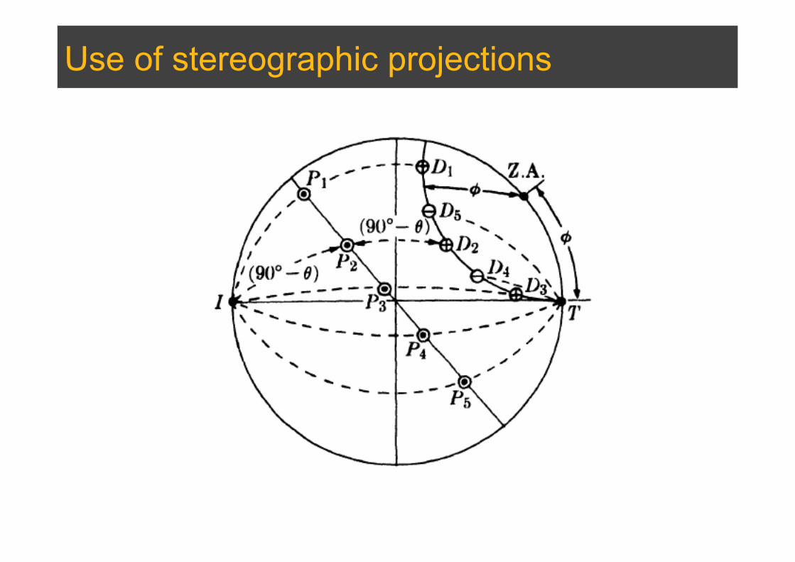
Use of stereographic projections
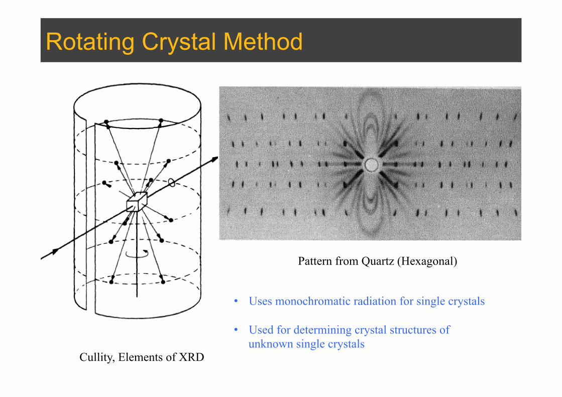
Rotating Crystal Method
Cullity, Elements of XRD
Pattern from Quartz (Hexagonal)
• Uses monochromatic radiation for single crystals
• Used for determining crystal structures of unknown single crystals
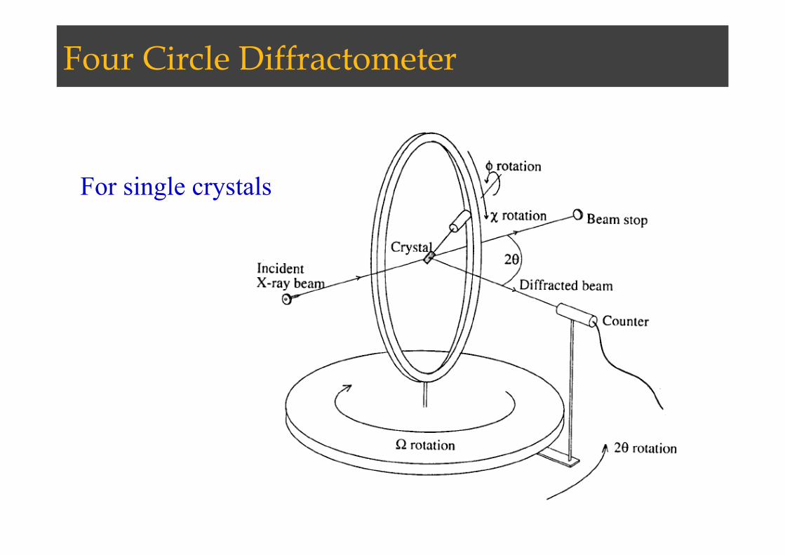
Four Circle Diffractometer
For single crystals

Two Circle Diffractometer
• For polycrystalline Materials

Powder Diffractometer

Diffraction under nonideal conditions
(BD Cullity, Elements of X-ray Diffraction)
Effect of crystallite size

Willamson-Hall Method
W.H.Hall (Acta Metall. 1, 22-31 (1953))
Size contribution to broadening
βc =kλ
t cosθ (t: crystallite size)
Strain contribution to broadeningβs =Cε tanθ (C: constant)βnet = βmeasured (size+strain+instrumental ) −βinstrumental
βnet =Cε tanθ + kλt cosθ
βnet cosθ =Cε sinθ +Kλ tKλ/
t
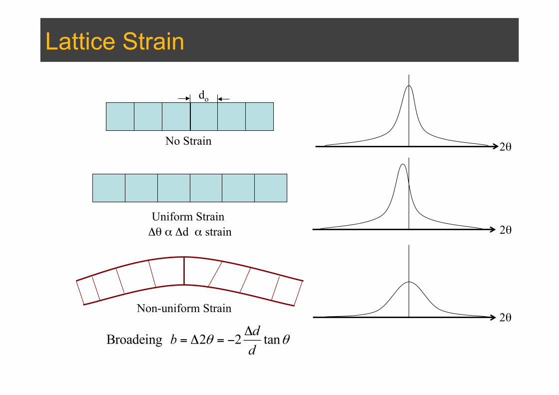
Lattice Strain
Broadeing 2 2 tanθ θΔ
= Δ = −dbd
Non-uniform Strain
Uniform Strain
No Strain
do
2θ
2θ
2θ
Δθ α Δd α strain
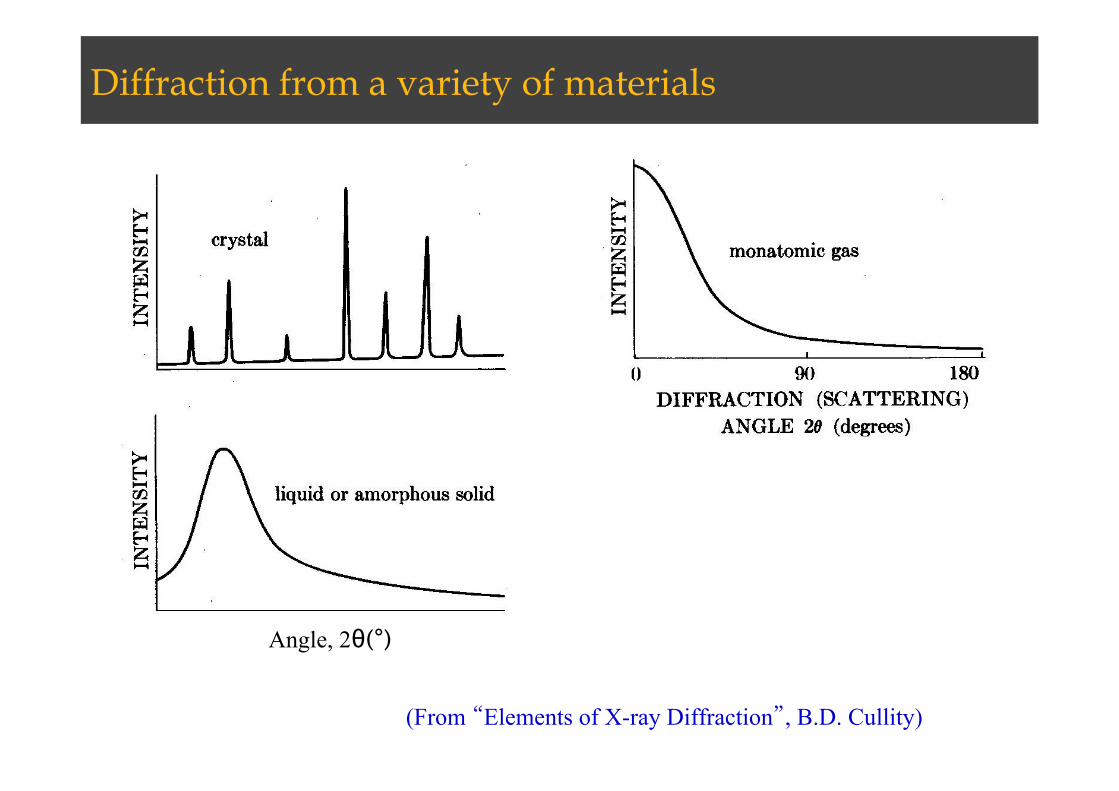
Diffraction from a variety of materials
(From “Elements of X-ray Diffraction”, B.D. Cullity)
Angle, 2θ(°)
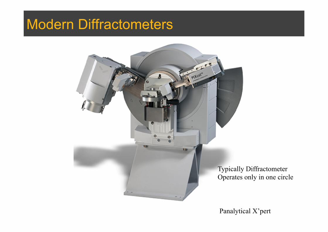
Modern Diffractometers
Panalytical X’pert
Typically Diffractometer Operates only in one circle
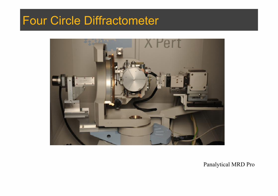
Four Circle Diffractometer
Panalytical MRD Pro

High Resolution XRD

Diffractometer components
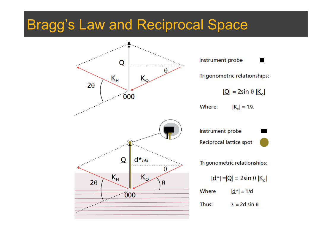
Bragg’s Law and Reciprocal Space

Alignment
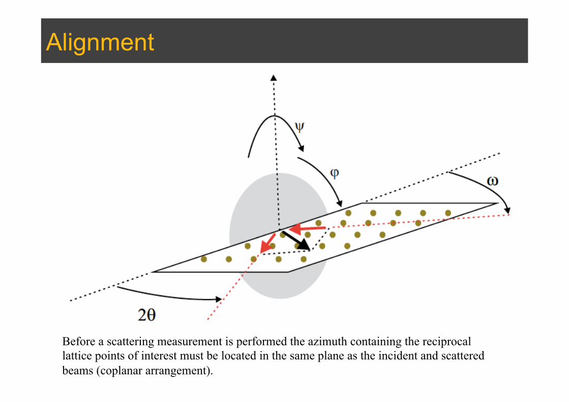
Alignment
Before a scattering measurement is performed the azimuth containing the reciprocal lattice points of interest must be located in the same plane as the incident and scattered beams (coplanar arrangement).
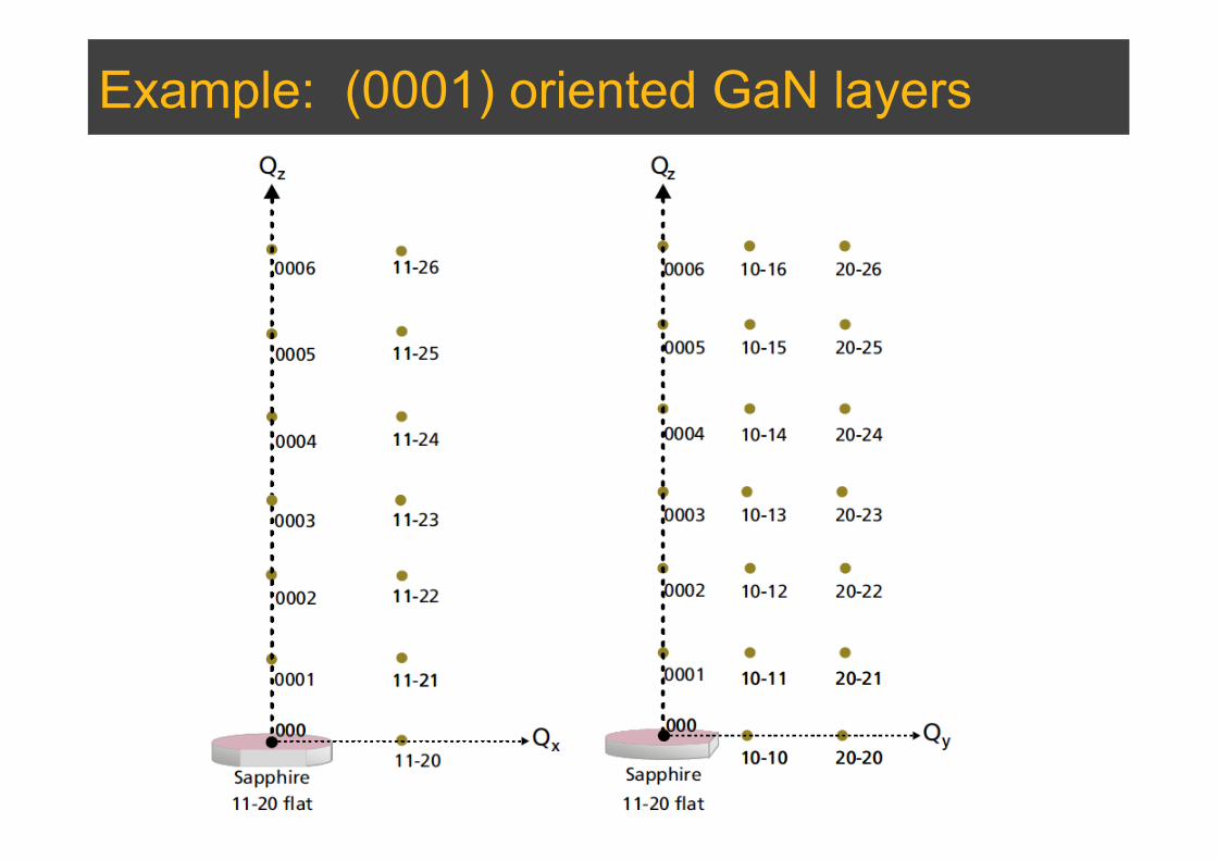
Example: (0001) oriented GaN layers
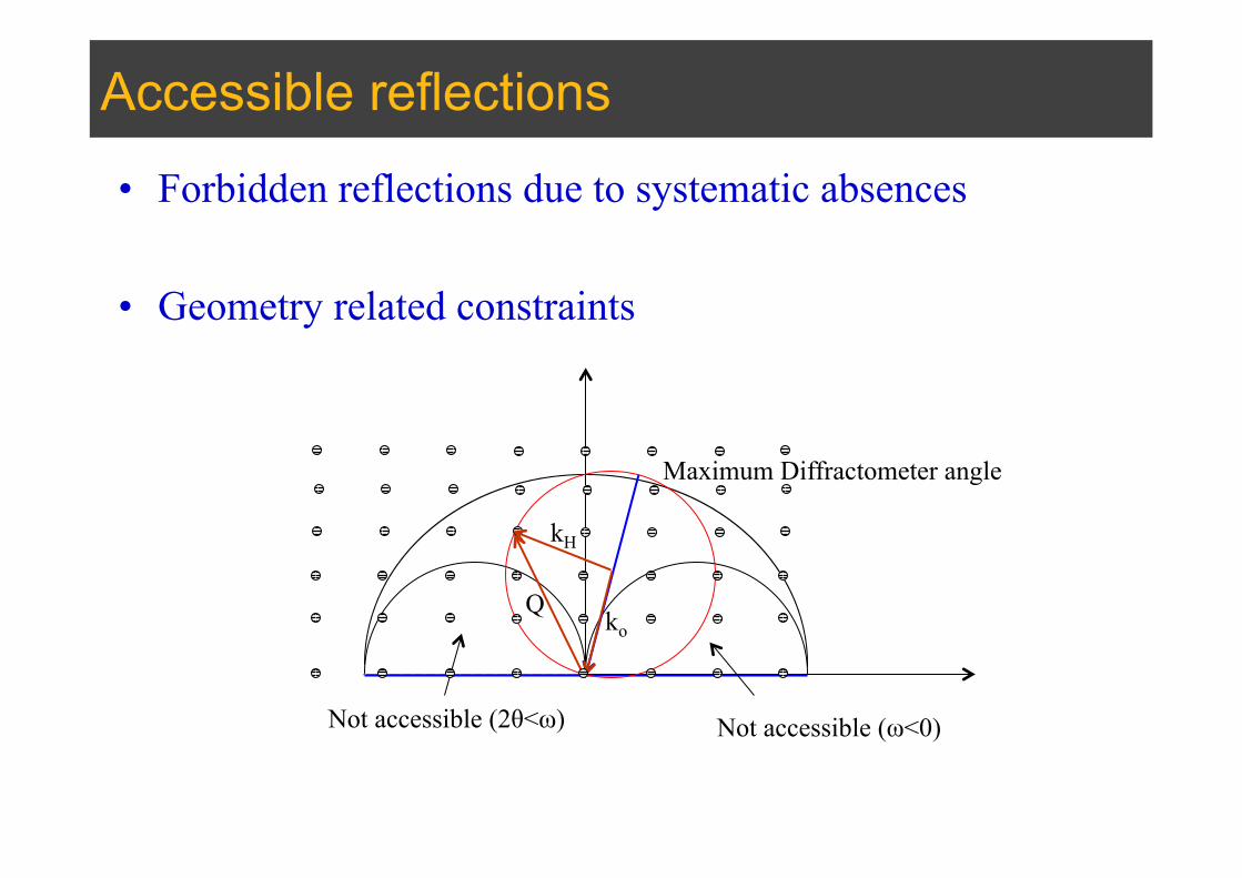
Accessible reflections
• Forbidden reflections due to systematic absences
• Geometry related constraints
Not accessible (ω<0) Not accessible (2θ<ω)
Maximum Diffractometer angle
ko
kH
Q

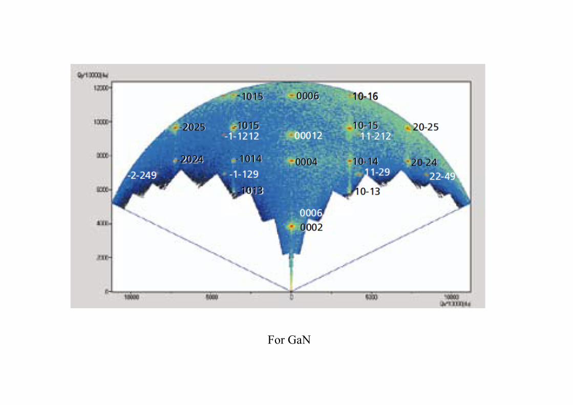
For GaN
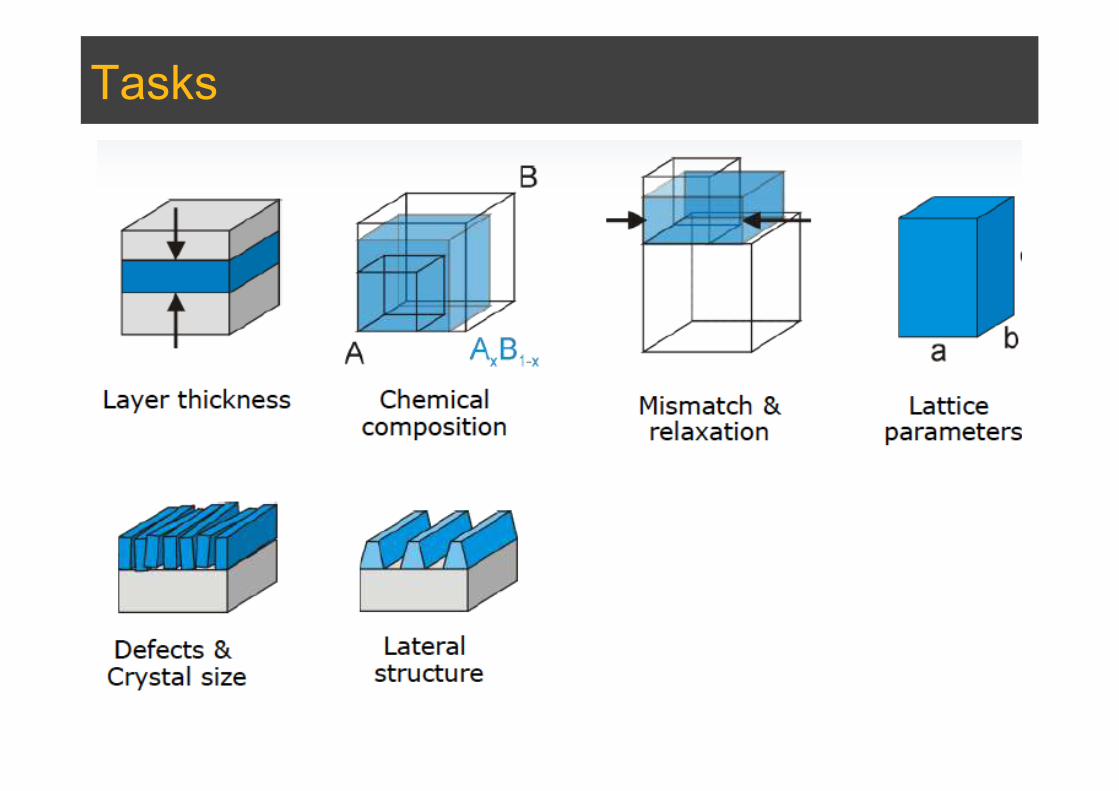
Tasks

Thin Films
Single Crystal Diffraction
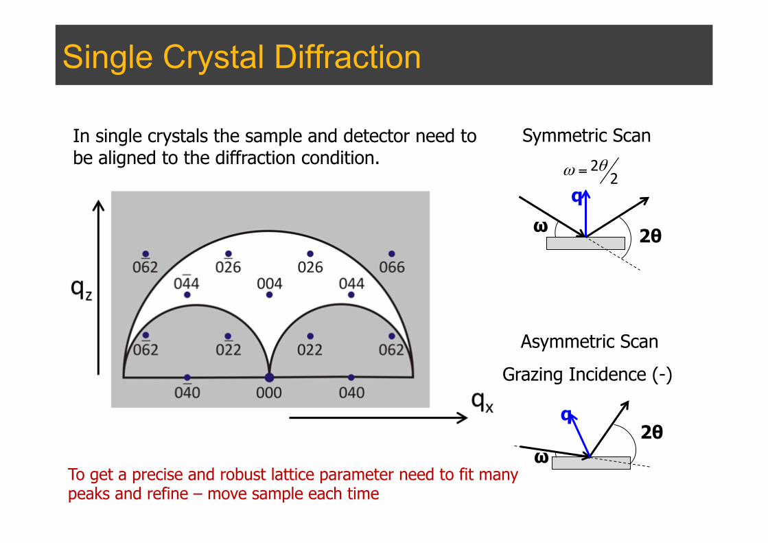
In single crystals the sample and detector need to be aligned to the diffraction condition.
q
ω 2θ
Symmetric Scan 2
2θω =
Asymmetric Scan
Grazing Incidence (-)
q
ω 2θ
To get a precise and robust lattice parameter need to fit many peaks and refine – move sample each time
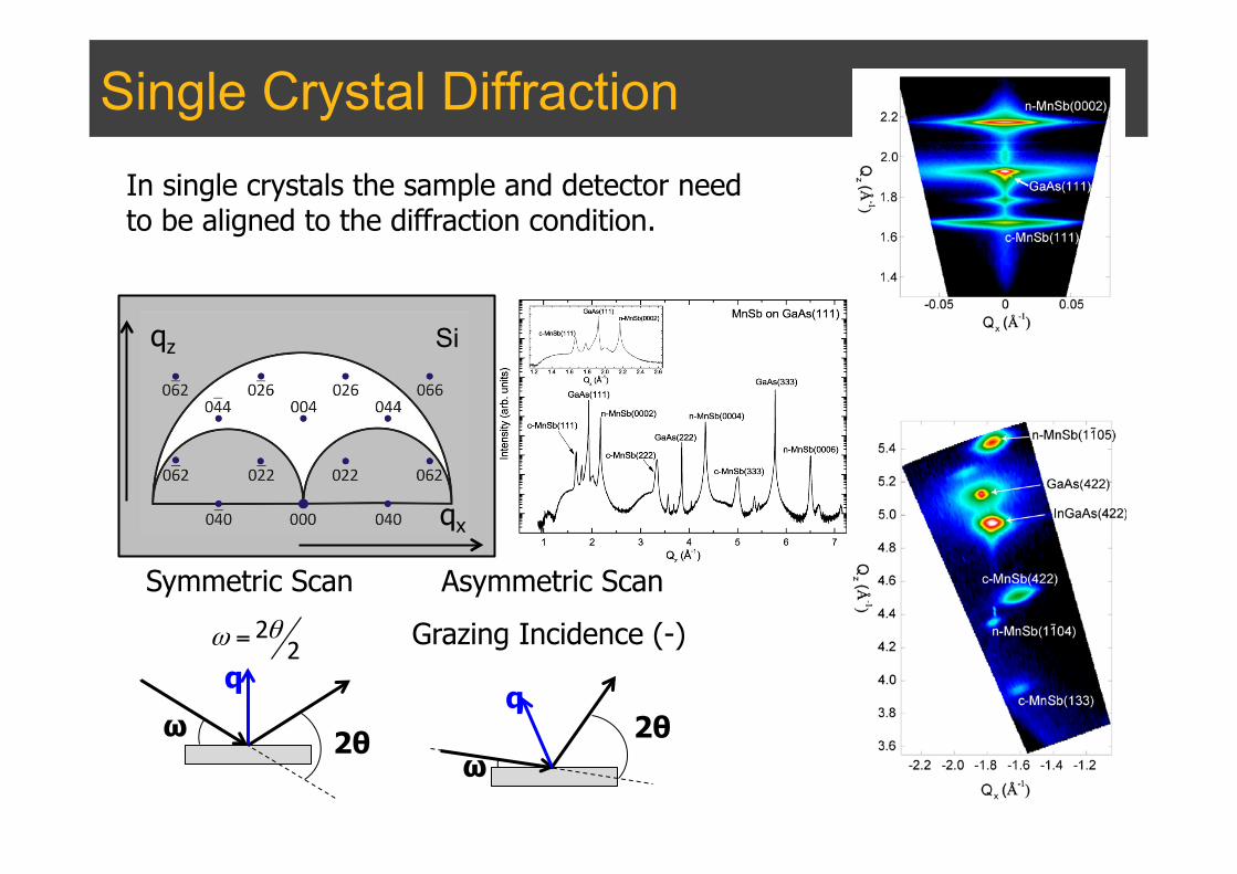
Single Crystal Diffraction In single crystals the sample and detector need to be aligned to the diffraction condition.
q
ω 2θ
Symmetric Scan 2
2θω =
Asymmetric Scan
Grazing Incidence (-)
q
ω 2θ
qz
qx
Si

Single Crystal Diffraction
θ-θ0 (µrad)
Angular acceptance is very high. Only accepts parallel beams and gives energy discrimination.
Removes height errors
Double Axis Triple Axis
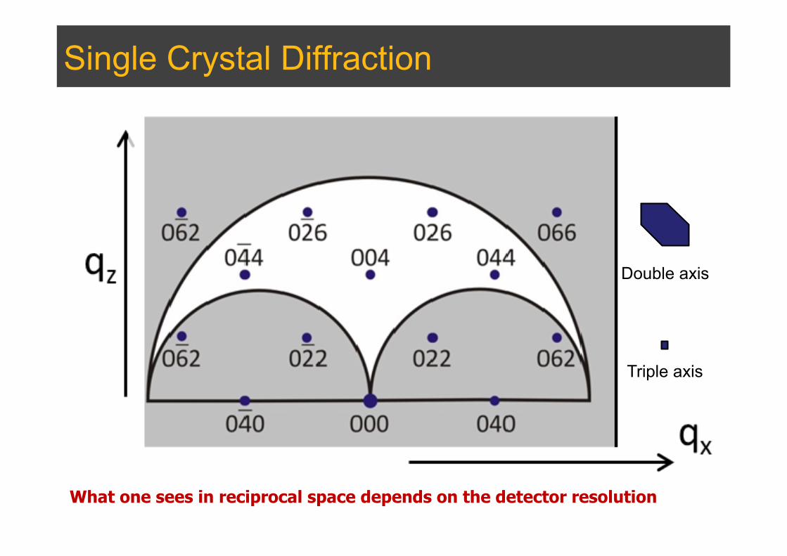
Single Crystal Diffraction
What one sees in reciprocal space depends on the detector resolution
Double axis
Triple axis
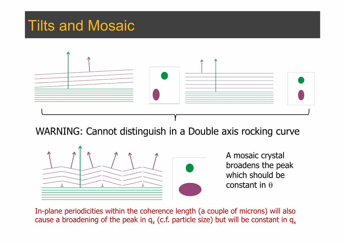
Tilts and Mosaic
WARNING: Cannot distinguish in a Double axis rocking curve
A mosaic crystal broadens the peak which should be constant in θ
In-plane periodicities within the coherence length (a couple of microns) will also cause a broadening of the peak in qx (c.f. particle size) but will be constant in qx

Epitaxial Layers
J. Aldous et al J. Cryst. Growth 357 (2012) 1-8
NiSb(~50nm)/GaAs
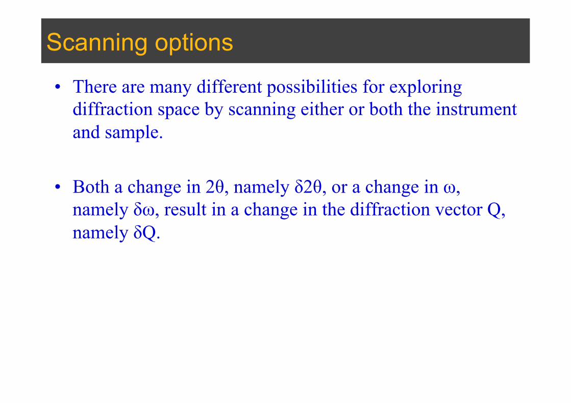
Scanning options
• There are many different possibilities for exploring diffraction space by scanning either or both the instrument and sample.
• Both a change in 2θ, namely δ2θ, or a change in ω, namely δω, result in a change in the diffraction vector Q, namely δQ.
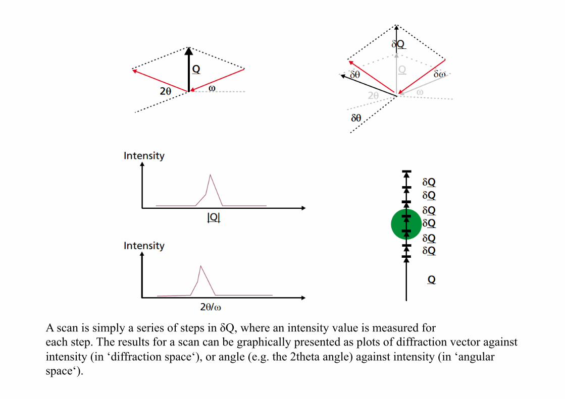
A scan is simply a series of steps in δQ, where an intensity value is measured for each step. The results for a scan can be graphically presented as plots of diffraction vector against intensity (in ‘diffraction space‘), or angle (e.g. the 2theta angle) against intensity (in ‘angular space‘).
Scan results
• The shape and size of the recorded profile is dependent both on the size and shape of the reciprocal lattice spot, the size and shape of the instrument probe and the direction in which they scan across one another.
• In the case of d-spacing measurements, it is the position or centroid of the scanned peak that is of primary importance.
Scan units
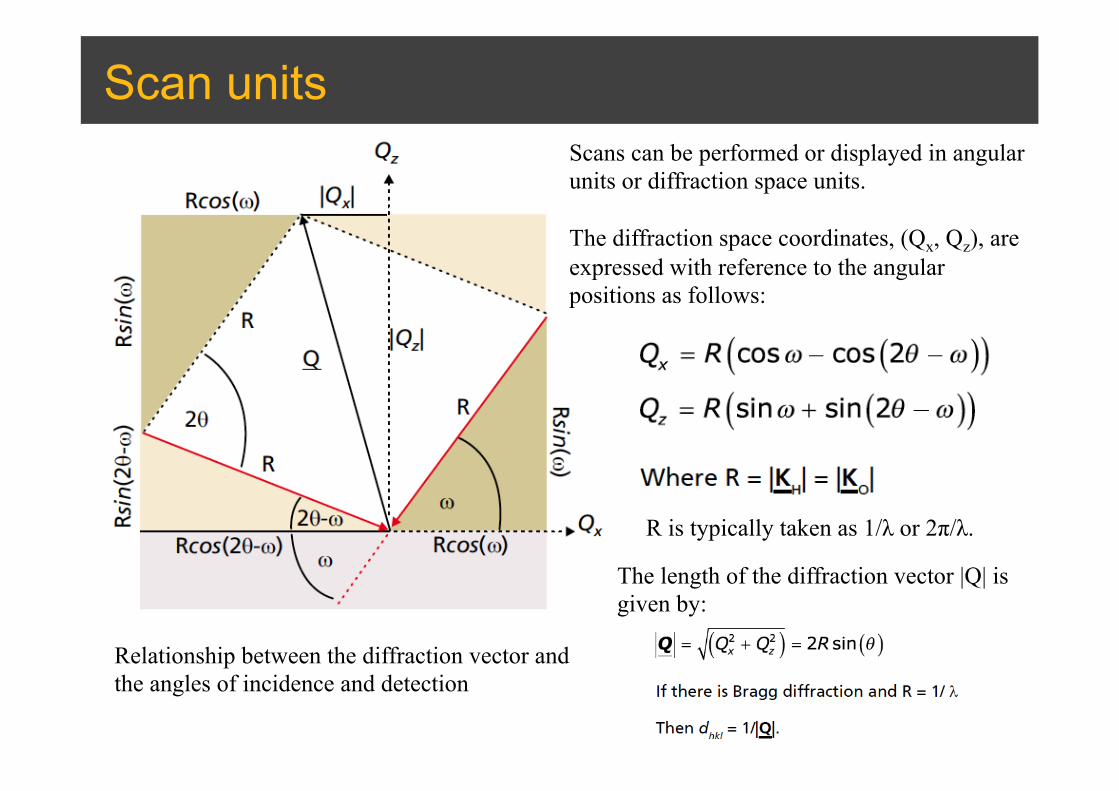
Relationship between the diffraction vector and the angles of incidence and detection
Scans can be performed or displayed in angular units or diffraction space units. The diffraction space coordinates, (Qx, Qz), are expressed with reference to the angular positions as follows:
R is typically taken as 1/λ or 2π/λ.
The length of the diffraction vector |Q| is given by:
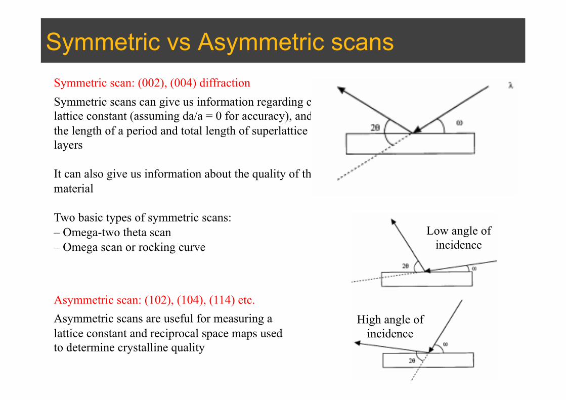
Symmetric vs Asymmetric scans
Symmetric scans can give us information regarding c lattice constant (assuming da/a = 0 for accuracy), and the length of a period and total length of superlattice layers It can also give us information about the quality of the material Two basic types of symmetric scans: – Omega-two theta scan – Omega scan or rocking curve
Symmetric scan: (002), (004) diffraction
Asymmetric scans are useful for measuring a lattice constant and reciprocal space maps used to determine crystalline quality
Asymmetric scan: (102), (104), (114) etc.
Low angle of incidence
High angle of incidence
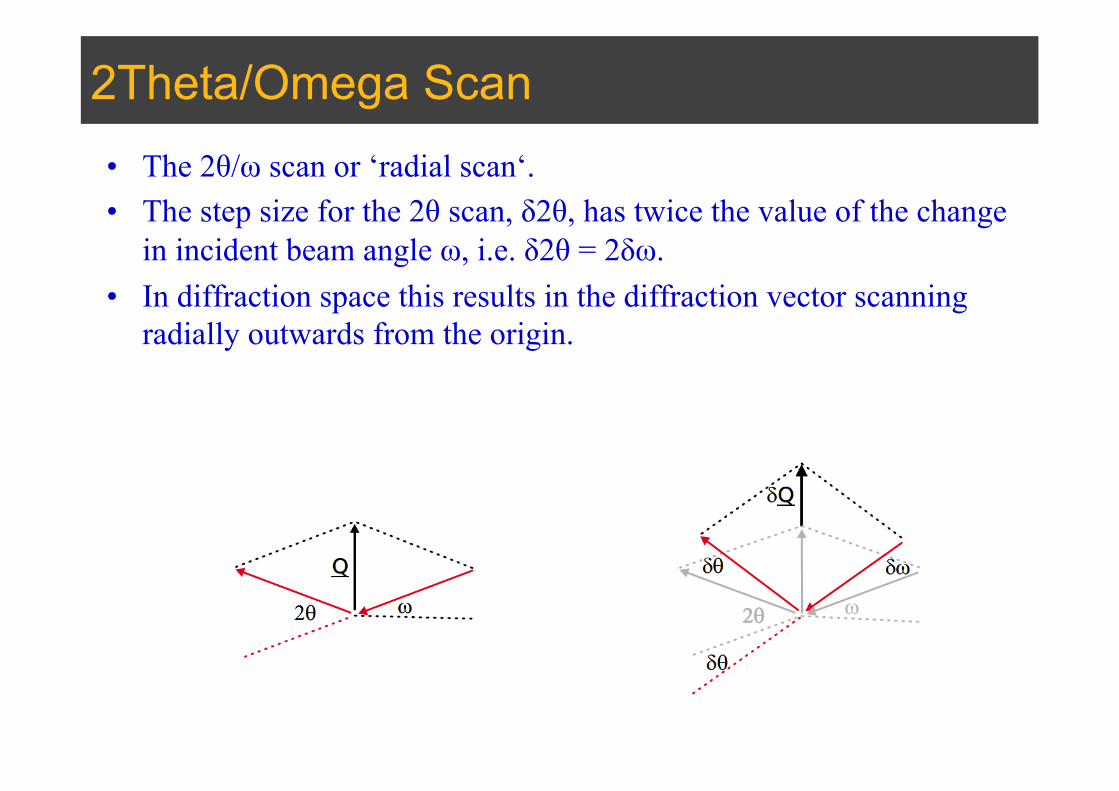
2Theta/Omega Scan • The 2θ/ω scan or ‘radial scan‘. • The step size for the 2θ scan, δ2θ, has twice the value of the change
in incident beam angle ω, i.e. δ2θ = 2δω. • In diffraction space this results in the diffraction vector scanning
radially outwards from the origin.

2Theta/Omega Scan
• A special case of radial scan in thin films is the ‘symmetric scan‘ in which ω = θ and the scan is then perpendicular to the sample surface.
• Bragg diffraction will occur if there are crystal planes parallel to the surface and when θ = θBragg.
• The intensity of peaks usually proportional to the thickness of the layers • The ω-2θ scans give the composition of the respective layers in the entire structure

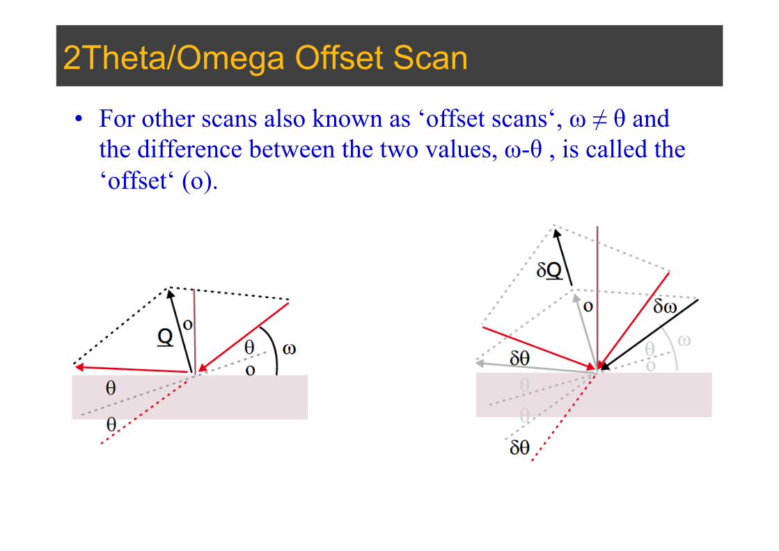
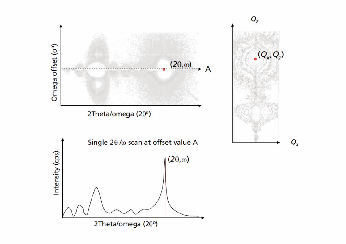
2Theta/Omega Offset Scan
• For other scans also known as ‘offset scans‘, ω ≠ θ and the difference between the two values, ω-θ , is called the ‘offset‘ (o).
2Theta/Omega vs Omega map
• A 2-axis reciprocal space map can be obtained when 2θ/ω scans are repeated for a sequence of offset values.
• The difference from one offset value to the next δo, is called the omega step size.
• The total difference between the largest and smallest offset values is called the omega range.

Omega Rocking Curve
• The source is fixed, the detector is fixed but the sample is rocked around the Bragg peak slightly
• The FWHM of the rocking curve is an important indicator of the material crystalline quality
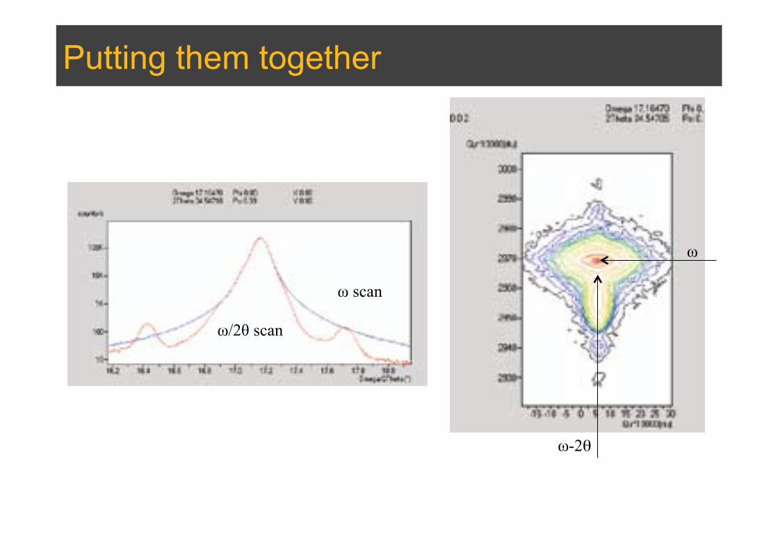
Putting them together
ω
ω-2θ
ω scan
ω/2θ scan

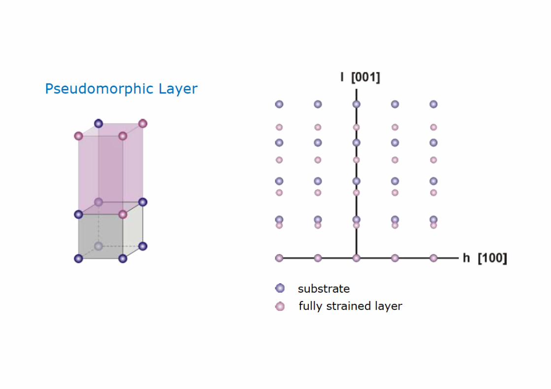
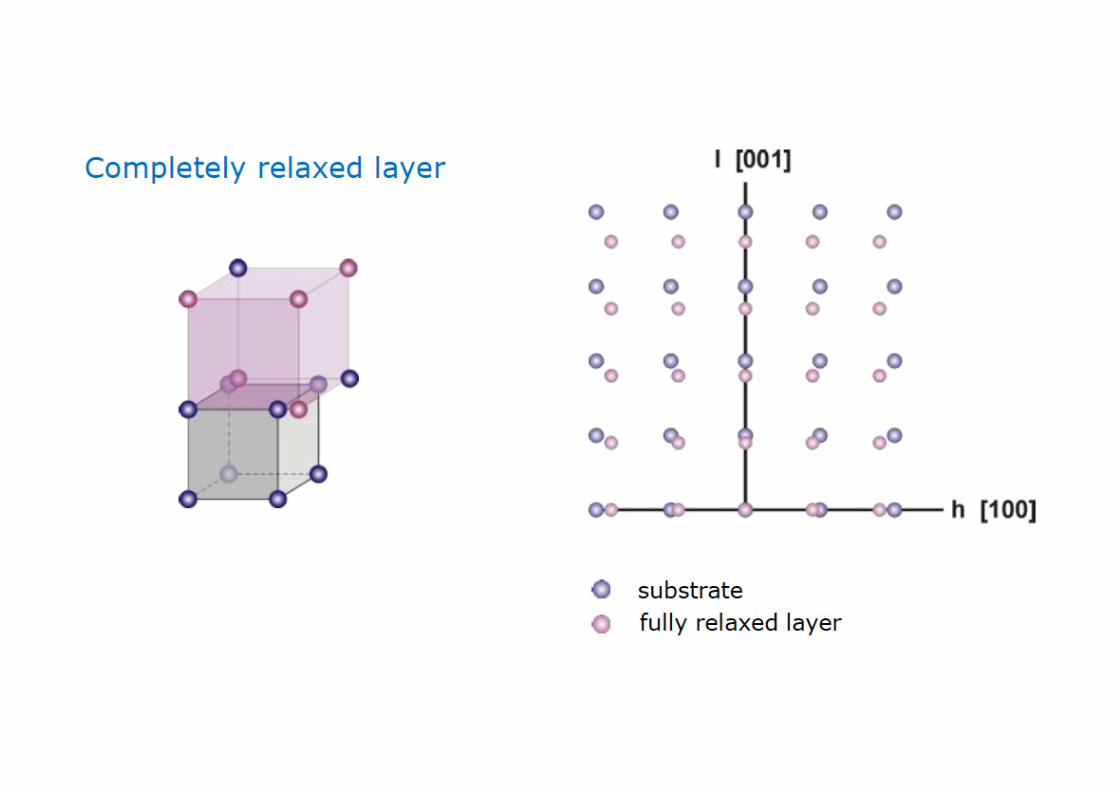
• For symmetric scans q is always perpendicular to the sample surface. qz is varied to measure c lattice constant
• For obtaining reciprocal space maps both the qz and qx are varied. • AlGaN in (a) and (b) are both pseudomorphic, but (b) has much worse quality. AlGaN in
(c) is not pseudomorphic as it does not have the same q
Crystal Quality
Measurement of plane spacing from RCM
• Uses in strain calculations and estimating structural distortions
• In a 2-D reciprocal space map it is important that the plane containing the reciprocal lattice spots of interest is coincident with the diffraction plane.
• The reciprocal space map contains Bragg spots that correlate with reciprocal lattice spots of the crystal.

Calculation of d-spacing (reference to 000) This method assumes that 2θ and ω zero positions are precisely calibrated
d-spacings of 11-20 and 0004 planes of GaN
Correct only if the sample and goniometer are precisely aligned and if there is no tilt of the GaN unit cell with respect to the surface. i.e. ω = 0 || (0001) GaN.
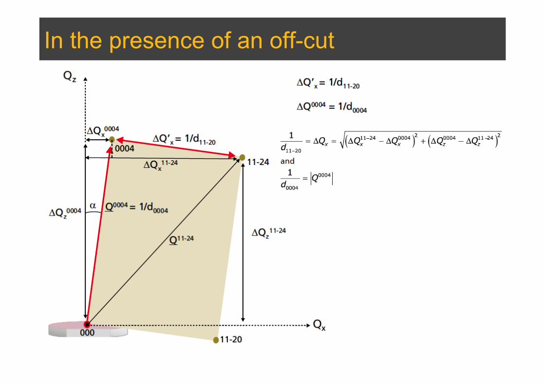
In the presence of an off-cut

Rocking curve and d-spacing • The peak on the rocking curve corresponds to the centroid of the
Bragg peak in reciprocal space. • To achieve this it is necessary for the crystal layers to have almost
no defects so that their peaks are not too broad. • For well-behaved materials, such as single crystal semiconductor
device structures which do not exhibit large loss of symmetry and whose crystal orientations have a simple relationship with the surface, rocking curves are extremely useful.
• When the layers contain many defects, the peaks can appear asymmetric and it may happen that the whole peak is not being captured in the rocking curve in which case it would be necessary to collect a reciprocal space map.

d-spacing from a symmetrical rocking curve where there is no layer tilt
The peak splitting between the layer reflection and the substrate reflection, Δω, in the rocking curve in this simple case is entirely due to the difference in plane spacing Δd and therefore Δω = Δθ.
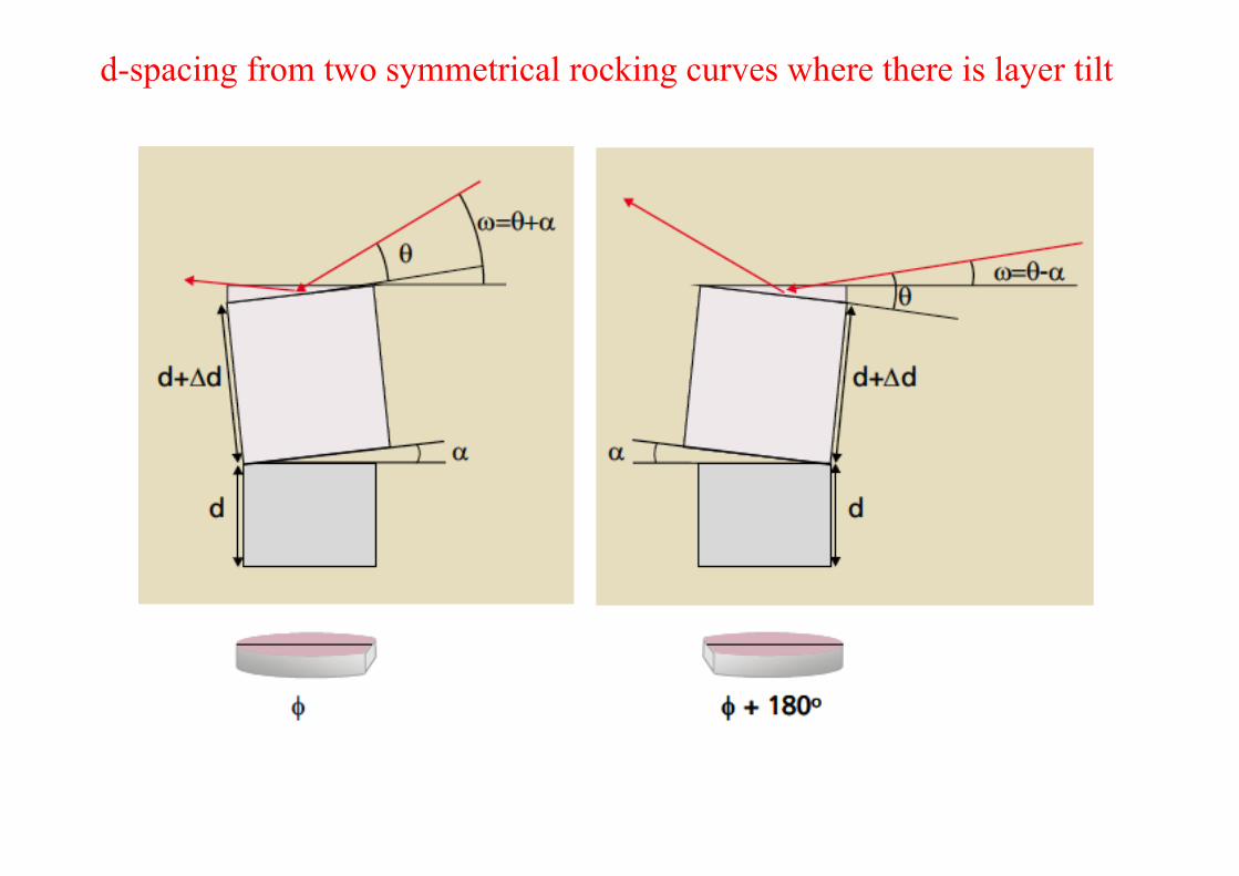
d-spacing from two symmetrical rocking curves where there is layer tilt

If there is any tilt of the layer unit cell with respect to the substrate unit cell then the measured Δω value at azimuth φ=0 (Δω0) will contain a component of tilt, Δα, i.e.
If the rocking curve measurement is repeated for the azimuth, φ+180°, then the sense of α is reversed whilst Δθ remains the same:

d-spacing from two asymmetrical rocking curves where there is layer tilt
Measurements of symmetric rocking curves provide values for plane spacing perpendicular to the sample surface, dz. Calculations of composition and strain require that plane spacings parallel to the interface dx are also measured. A measure of dx can be obtained using planes that are inclined.
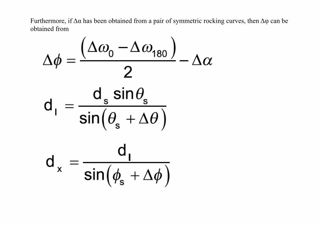
Furthermore, if Δα has been obtained from a pair of symmetric rocking curves, then Δφ can be obtained from
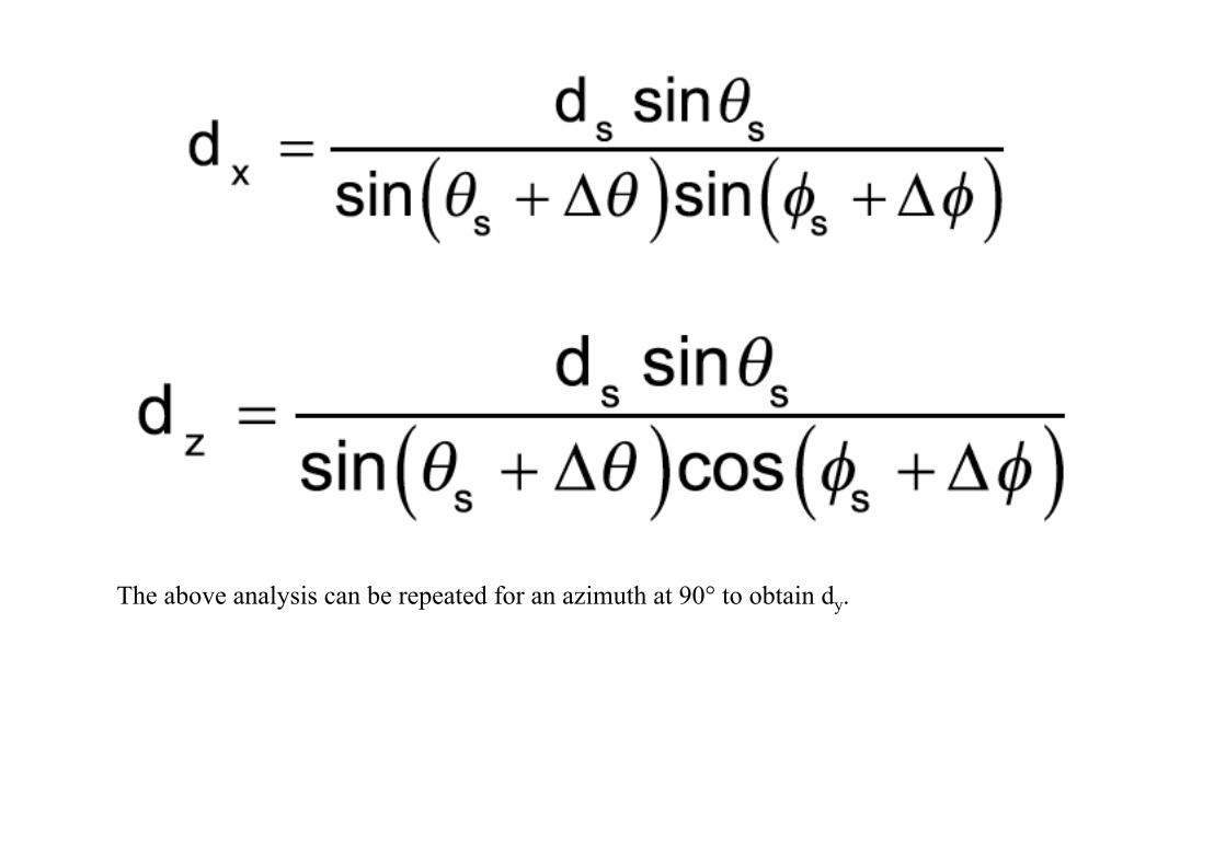
The above analysis can be repeated for an azimuth at 90° to obtain dy.

Summary • In short, one can use HRXRD analysis for in-depth analysis
– Strain – Composition – Layer thickness – Mismatch – Epitaxy
• References: – Paul Fewster, Reciprocal Space Mapping, Critical Reviews in
Solid State and Materials Sciences, 22:2, 69-110 (1997) – Paul Fewster, X-ray Scattering from Semiconductors, Imperial
College Press – P. Kidd, XRD of gallium nitride and related compounds: strain,
composition and layer thickness