Embed Size (px)
Citation preview
X-MDA-1™ User Manual
Table of ContentsTrademark and Copyright Information................................................................................................................ 3
Warranty................................................................................................................................................................ 4
Installation Guidelines (Read Before Installing)................................................................................................ 5
Section 1: Introduction......................................................................................................................................... 6
1.1 X-MDA Models......................................................................................................................................... 7
1.2 Davis Instruments Integrated Sensor Suites (ISS)............................................................................... 8
Section 2: Installation and X-320M™ Setup..................................................................................................... 10
2.1 Installation Preparation......................................................................................................................... 10
2.2 X-MDA-1™ Installation.......................................................................................................................... 11
2.3 X-320M Sensor Configuration.............................................................................................................. 13
2.4 I/O........................................................................................................................................................... 13
2.5 Wind Speed............................................................................................................................................ 13
2.6 Wind Direction....................................................................................................................................... 13
2.7 Rain......................................................................................................................................................... 14
2.8 Temperature........................................................................................................................................... 14
2.9 Relative Humidity.................................................................................................................................. 14
2.10 Solar Radiation.................................................................................................................................... 14
2.11 UV Sensor............................................................................................................................................ 15
2.12 Barometric Pressure........................................................................................................................... 15
2.13 Soil Moisture........................................................................................................................................ 15
Section 3: Optional Sensors and Accessories................................................................................................. 16
3.1 Additional Sensors................................................................................................................................ 16
3.2 Accessories........................................................................................................................................... 17
Page 2 Xytronix Research & Design, Inc.
X-MDA-1™ User Manual Trademark and Copyright Information
Trademark and Copyright InformationThis document is Copyright ©2013-2015 by Xytronix Research & Design, Inc. All rights reserved.
X-MDA-1TM, X-320™, X-320M™, WebRelay™, ControlByWeb™, and Xytronix Research & Design™ are trademarks of Xytronix Research & Design™, Inc. 2013.
All other trademarks are the property of their respective owners.
All parts of this product and design including but not limited to firmware, hardware design, schematics, PCB layout, concept, graphics, users manual, etc., are property of Xytronix Research & Design, Inc. ©2013. X-320M™ may not be opened, disassembled, copied or reverse-engineered.
No part of this manual may be reproduced or transmitted in any form or by any means, electronic or mechanical, including photocopying or scanning, for any purpose other than the personal use by the purchaser of this product. Xytronix Research & Design, Inc., assumes no responsibility for any errors that may appear in this document.
Whereas reasonable effort has been made to make the information in this document as useful and accurate as possible, Xytronix Research & Design, Inc. assumes no responsibility for the application, usefulness, or completeness of the information contained herein. Under no circumstance will Xytronix Research & Design, Inc. be responsible or liable for any damages or losses including direct, indirect, special, incidental, or consequential damages or losses arising from either the use of any information contained within this manual or the use of any products or services referenced in this manual.
Xytronix Research & Design, Inc. reserves the right to change any product’s features, specifications, documentation, warranties, fee schedules, and conditions at any time and without notice.
Xytronix Research & Design, Inc. Page 3
Warranty X-MDA-1™ User Manual
WarrantyThis Xytronix Research & Design, Inc. product has a warranty against defects in material and workmanship for a period of one year from the date of shipment. During the warranty period, Xytronix Research & Design, Inc. will, at its option, either repair or replace products that prove to be defective. This warranty is extended to the original purchaser of the equipment only.
For warranty service or repair, the product must be properly packaged, and returned to Xytronix Research & Design, Inc. The purchaser shall prepay all charges for shipping to Xytronix Research & Design, Inc., and Xytronix Research & Design, Inc. will pay the shipping charges to return the product to the purchaser as long as the product is shipped within the United States. If the product is shipped outside of the United States, the purchaser shall pay all shipping charges, duties, and taxes.
Limitation
The foregoing warranty shall not apply to defects or damage resulting from improper use or misuse, unauthorized repair, tampering, modification, improper connection, or operation outside the electrical/environmental specifications for the product. Further, the warranty does not cover Acts of God, such as fire, flood, hurricanes, and tornadoes. This warranty does not cover damage to property, equipment, direct, indirect, consequential, or incidental damage (including damage for loss of business profit, business interruption, loss of data, and the like) arising out of the use or misuse of this product.
UNDER NO CIRCUMSTANCES WILL THE LIABILITY OF XYTRONIX RESEARCH & DESIGN, INC. TO THE PURCHASER OR ANY OTHER PARTY EXCEED THE ORIGINAL PURCHASE PRICE OF THE PRODUCT, REGARDLESS OF THE FORM OF THE CLAIM. No other warranty is expressed or implied. Xytronix Research & Design, Inc. specifically disclaims the implied warranties or merchantability and fitness for a particular purpose. Some jurisdictions may not allow the exclusion of limitation of liability for consequential or incidental damage.
Page 4 Xytronix Research & Design, Inc.
X-MDA-1™ User Manual Installation Guidelines (Read Before Installing)
Installation Guidelines (Read Before Installing)- This unit must be installed by qualified personnel.- This unit must not be installed directly outdoors.- This unit must not be used for medical, life saving purposes, or for any purpose where its failure
could cause serious injury or the loss of life.- This unit must not be used in any way where its function or failure could cause significant loss or
property damage.
Xytronix Research & Design, Inc. Page 5
Introduction X-MDA-1™ User Manual
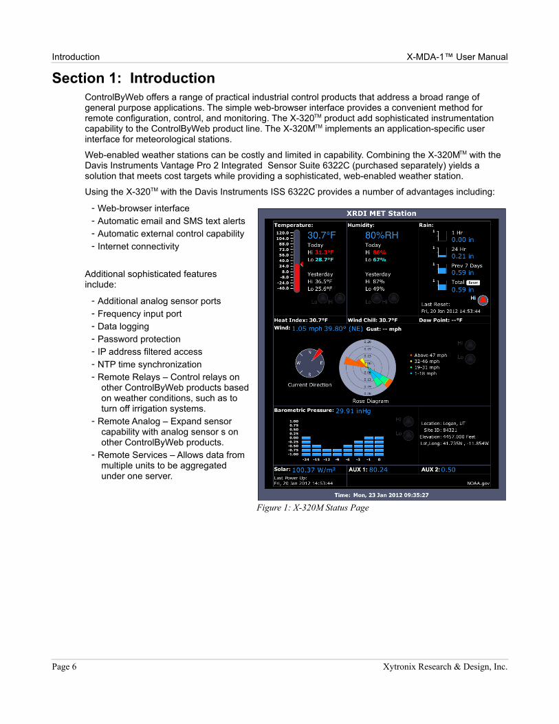
Section 1: IntroductionControlByWeb offers a range of practical industrial control products that address a broad range of general purpose applications. The simple web-browser interface provides a convenient method for remote configuration, control, and monitoring. The X-320TM product add sophisticated instrumentation capability to the ControlByWeb product line. The X-320MTM implements an application-specific user interface for meteorological stations.
Web-enabled weather stations can be costly and limited in capability. Combining the X-320MTM with the Davis Instruments Vantage Pro 2 Integrated Sensor Suite 6322C (purchased separately) yields a solution that meets cost targets while providing a sophisticated, web-enabled weather station.
Using the X-320TM with the Davis Instruments ISS 6322C provides a number of advantages including:
- Web-browser interface- Automatic email and SMS text alerts- Automatic external control capability - Internet connectivity
Additional sophisticated features include:
- Additional analog sensor ports- Frequency input port- Data logging- Password protection- IP address filtered access - NTP time synchronization- Remote Relays – Control relays on
other ControlByWeb products based on weather conditions, such as to turn off irrigation systems.
- Remote Analog – Expand sensor capability with analog sensor s on other ControlByWeb products.
- Remote Services – Allows data from multiple units to be aggregated under one server.
Page 6 Xytronix Research & Design, Inc.
Figure 1: X-320M Status Page
X-MDA-1™ User Manual Introduction
1.1 X-MDA Models
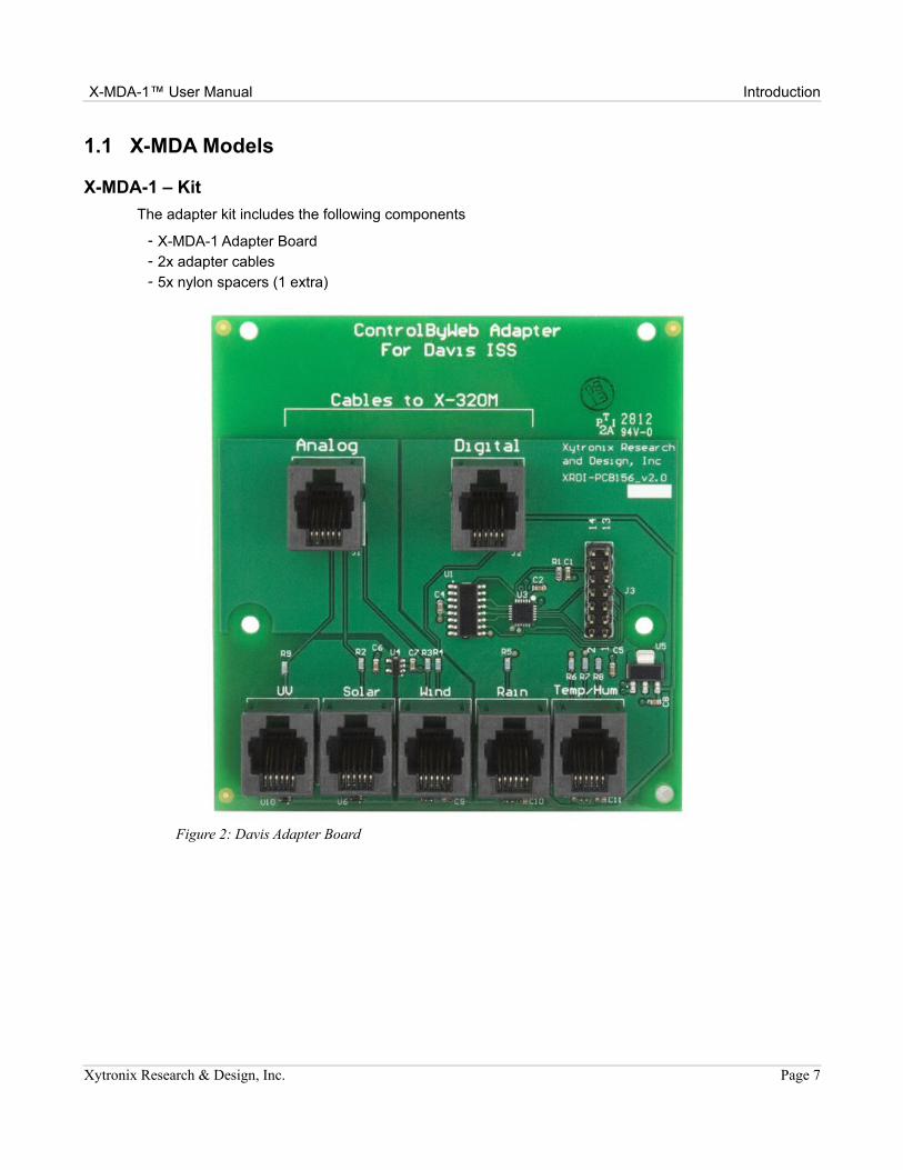
X-MDA-1 – Kit
The adapter kit includes the following components
- X-MDA-1 Adapter Board- 2x adapter cables- 5x nylon spacers (1 extra)
Xytronix Research & Design, Inc. Page 7
Figure 2: Davis Adapter Board
Introduction X-MDA-1™ User Manual
1.2 Davis Instruments Integrated Sensor Suites (ISS)Either of the Cabled Vantage Pro sensor suites may be uses with the X-320MTM. The stations are modular and may be expanded as needed. Applicable accessories are shown with each ISS.
Cabled Vantage Pro2, 6322C
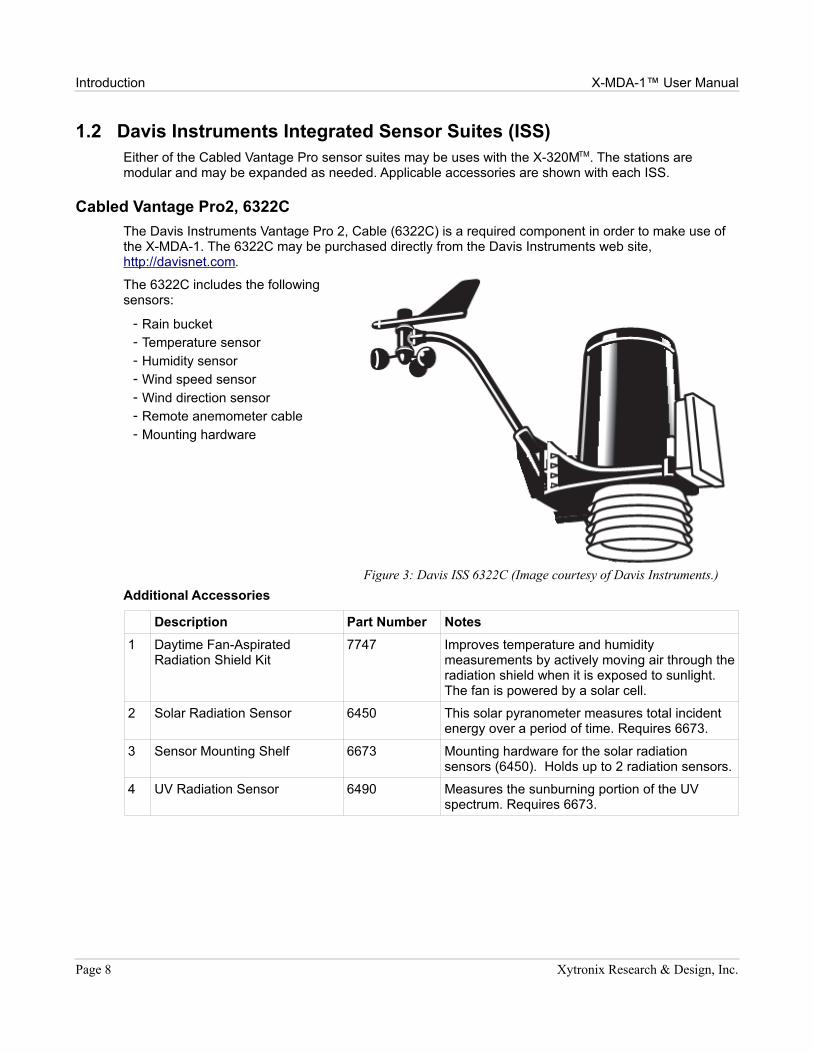
The Davis Instruments Vantage Pro 2, Cable (6322C) is a required component in order to make use of the X-MDA-1. The 6322C may be purchased directly from the Davis Instruments web site, http://davisnet.com.
The 6322C includes the following sensors:
- Rain bucket- Temperature sensor- Humidity sensor - Wind speed sensor- Wind direction sensor- Remote anemometer cable- Mounting hardware
Additional Accessories
Description Part Number Notes
1 Daytime Fan-Aspirated Radiation Shield Kit
7747 Improves temperature and humidity measurements by actively moving air through the radiation shield when it is exposed to sunlight. The fan is powered by a solar cell.
2 Solar Radiation Sensor 6450 This solar pyranometer measures total incident energy over a period of time. Requires 6673.
3 Sensor Mounting Shelf 6673 Mounting hardware for the solar radiation sensors (6450). Holds up to 2 radiation sensors.
4 UV Radiation Sensor 6490 Measures the sunburning portion of the UV spectrum. Requires 6673.
Page 8 Xytronix Research & Design, Inc.
Figure 3: Davis ISS 6322C (Image courtesy of Davis Instruments.)
X-MDA-1™ User Manual Introduction
Vantage Pro2 Plus, 6327C
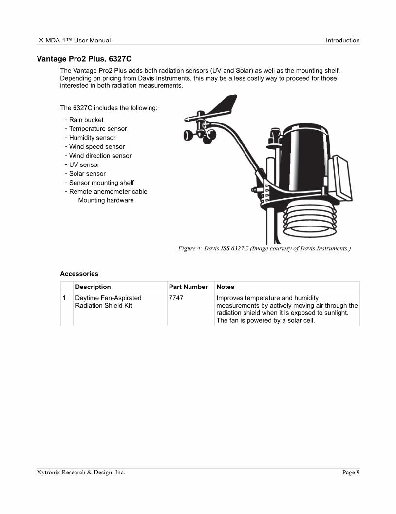
The Vantage Pro2 Plus adds both radiation sensors (UV and Solar) as well as the mounting shelf. Depending on pricing from Davis Instruments, this may be a less costly way to proceed for those interested in both radiation measurements.
The 6327C includes the following:
- Rain bucket- Temperature sensor- Humidity sensor - Wind speed sensor- Wind direction sensor- UV sensor- Solar sensor- Sensor mounting shelf- Remote anemometer cable
Mounting hardware
Accessories
Description Part Number Notes
1 Daytime Fan-Aspirated Radiation Shield Kit
7747 Improves temperature and humidity measurements by actively moving air through the radiation shield when it is exposed to sunlight. The fan is powered by a solar cell.
Xytronix Research & Design, Inc. Page 9
Figure 4: Davis ISS 6327C (Image courtesy of Davis Instruments.)
Installation and X-320M™ Setup X-MDA-1™ User Manual
Section 2: Installation and X-320M™ Setup
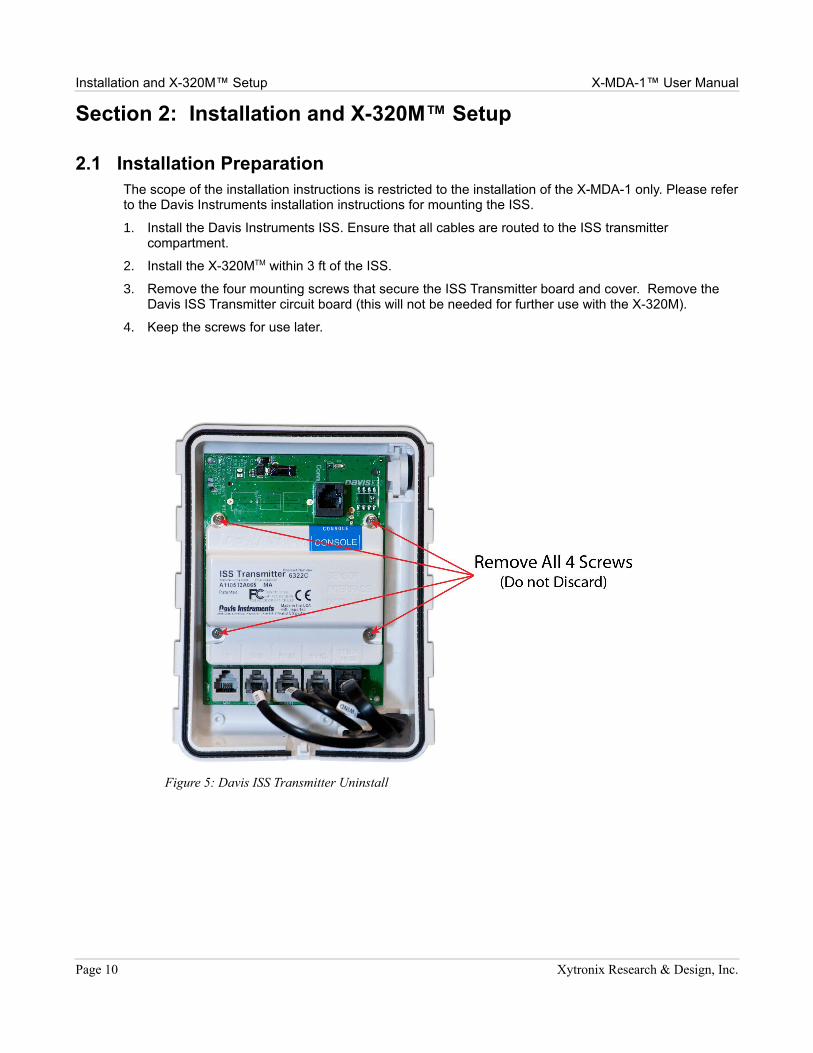
2.1 Installation PreparationThe scope of the installation instructions is restricted to the installation of the X-MDA-1 only. Please refer to the Davis Instruments installation instructions for mounting the ISS.
1. Install the Davis Instruments ISS. Ensure that all cables are routed to the ISS transmitter compartment.
2. Install the X-320MTM within 3 ft of the ISS.
3. Remove the four mounting screws that secure the ISS Transmitter board and cover. Remove the Davis ISS Transmitter circuit board (this will not be needed for further use with the X-320M).
4. Keep the screws for use later.
Page 10 Xytronix Research & Design, Inc.
Figure 5: Davis ISS Transmitter Uninstall
X-MDA-1™ User Manual Installation and X-320M™ Setup
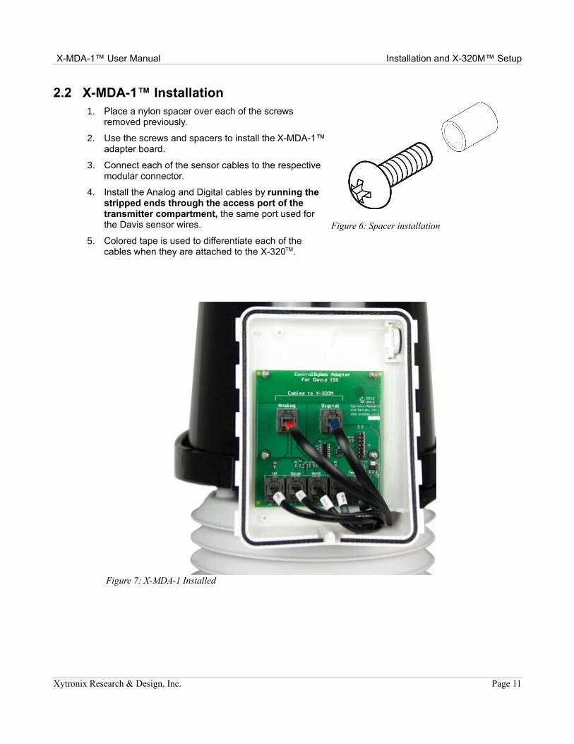
2.2 X-MDA-1™ Installation1. Place a nylon spacer over each of the screws
removed previously.
2. Use the screws and spacers to install the X-MDA-1™ adapter board.
3. Connect each of the sensor cables to the respective modular connector.
4. Install the Analog and Digital cables by running the stripped ends through the access port of the transmitter compartment, the same port used for the Davis sensor wires.
5. Colored tape is used to differentiate each of the cables when they are attached to the X-320TM.
Xytronix Research & Design, Inc. Page 11
Figure 6: Spacer installation
Figure 7: X-MDA-1 Installed
Installation and X-320M™ Setup X-MDA-1™ User Manual
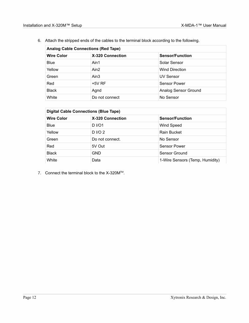
6. Attach the stripped ends of the cables to the terminal block according to the following.
Analog Cable Connections (Red Tape)
Wire Color X-320 Connection Sensor/Function
Blue Ain1 Solar Sensor
Yellow Ain2 Wind Direction
Green Ain3 UV Sensor
Red +5V RF Sensor Power
Black Agnd Analog Sensor Ground
White Do not connect No Sensor
Digital Cable Connections (Blue Tape)
Wire Color X-320 Connection Sensor/Function
Blue D I/O1 Wind Speed
Yellow D I/O 2 Rain Bucket
Green Do not connect. No Sensor
Red 5V Out Sensor Power
Black GND Sensor Ground
White Data 1-Wire Sensors (Temp, Humidity)
7. Connect the terminal block to the X-320MTM.
Page 12 Xytronix Research & Design, Inc.
X-MDA-1™ User Manual Installation and X-320M™ Setup
2.3 X-320M Sensor ConfigurationPlease refer the X-320TM and X-320MTM manuals for set up of the network parameters, email, NTP, logging, and other general settings. The following instructions are for the use and configuration of the Davis Sensors only.
The following instructions presume that the user is familiar with the X-320 interface or can refer to the product user manual when necessary. Specific instructions, such as submitting changes or selecting tabs, are omitted; only the sensor configuration settings are given.
2.4 I/O
I/O 1 (Wind Speed)
Mode: Input
Pull-Up/Down Select: Pull-Up Resistor
Counter Options: Increment when input on
Debounce Time (ms): 1
I/O 2 (Rain Bucket)
Mode: Input
Pull-Up/Down Select: Pull-Up Resistor
Counter Options: Increment when input off
2.5 Wind SpeedSensor Connection: Rate 1
Slope: 2.25
Offset: 0.00
Avg. Period: 2 min (This is a typical setting and may be adjusted by the user.)
Units: mph
2.6 Wind DirectionSensor Connection: Analog 2
Slope: 72
Offset: 0
Avg. Period: 2 min
Units: Degrees
Xytronix Research & Design, Inc. Page 13
Installation and X-320M™ Setup X-MDA-1™ User Manual
2.7 RainSensor Connection: Counter 2
Slope: 0.01
Offset: 0.00
Units: in
2.8 TemperatureThe 1-Wire bus is used for compatible digital temperature and humidity sensors. All compatible sensors have a unique 1-Wire address. The user will need to select the correct address for the corresponding sensor for each relevant function.
Sensor Connection: 1-Wire Bus
1-Wire Address: (User selects unique sensor ID. Refer to the user manual.)
For Fahrenheit
Slope: 1.0
Offset: 0
Units: ºF
For Celsius
Slope: 0.5555
Offset: -17.7778
Units: ºC
2.9 Relative HumiditySensor Connection: 1-Wire Bus
1-Wire Address: (User selects unique sensor ID. Refer to the user manual.)
Slope: 1.00
Offset: 0.00
Units: %RH
2.10 Solar RadiationSensor Connection: Analog 1
Slope: 598.799
Offset: 0.00
Units: W/m2
Note: Solar radiation configuration can be validated at clearskycalculator.com. The calculations assume a clear sky and should be within about 3% within one hour of solar noon.
Page 14 Xytronix Research & Design, Inc.
X-MDA-1™ User Manual Installation and X-320M™ Setup
2.11 UV SensorSensor Connection: Analog 3
Slope: 6.4
Offset: 0
Units: UV index
2.12 Barometric PressureThe following settings are for the Apogee Instruments SB-110. See Section 3 for additional information.
Sensor Connection: (The user may connect this sensor to any available analog port. Please refer to the user manual.)
Slope: 6.437
Offset: 3.637
Adjustment: Sea Level
Units: inHg
2.13 Soil MoistureThe following settings are for the Irrometer Soil Moisture Sensor. See Section 3 for additional information.
Sensor Connection: (The user may connect this sensor to any available analog port. Please refer to the user manual.)
Slope: 85.35714
Offset: 0.00
Units: cb
A soil moisture levels above 239 are error indications. 247.53 (2.9 V) indicates frozen sensor. 256.07 (3.0V) indicates an open circuit. Refer to Watermark documentation for more information. Please keep in mind that the slope value may affect the error codes and direct probing of the voltage values or temporarily setting the slope to 1 may be required to verify the error state.
Xytronix Research & Design, Inc. Page 15
Optional Sensors and Accessories X-MDA-1™ User Manual
Section 3: Optional Sensors and Accessories
3.1 Additional SensorsThe X-320M™ is compatible with a wide variety of commercial and scientific sensors. Please contact Xytronix for a list of compatible sensors.
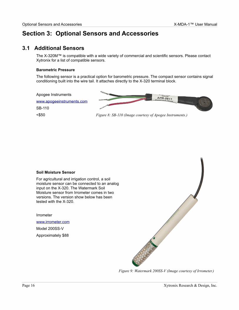
Barometric Pressure
The following sensor is a practical option for barometric pressure. The compact sensor contains signal conditioning built into the wire tail. It attaches directly to the X-320 terminal block.
Apogee Instruments
www.apogeeinstruments.com
SB-110
<$50
Soil Moisture Sensor
For agricultural and irrigation control, a soil moisture sensor can be connected to an analog input on the X-320. The Watermark Soil Moisture sensor from Irrometer comes in two versions. The version show below has been tested with the X-320.
Irrometer
www.irrometer.com
Model 200SS-V
Approximately $88
Page 16 Xytronix Research & Design, Inc.
Figure 8: SB-110 (Image courtesy of Apogee Instruments.)
Figure 9: Watermark 200SS-V (Image courtesy of Irrometer.)
X-MDA-1™ User Manual Optional Sensors and Accessories
3.2 AccessoriesThe Vantage Pro ISS may be pole or panel mounted. System installations vary widely. The following are some accessories that may be useful in setting up a meteorological station. The listings below are provided as a reference only and do not represent an endorsement, guarantee of suitability, or compatibility. The user is advised to explore appropriate hardware to meet their specific needs.
POE Splitter
A POE splitter may be used to supply power to a remote installation of the X-320M™. The splitter is used on the X-320M™ end of the CAT5 cable. It will provide regulated power to the X-320M™. A POE power injector is required on the other end of the CAT5 cable. The DC barrel connector on the splitter will need to be removed in order to connect it to the X-320M™ power input terminals.
For help in finding a compatible POE splitter, please contact our sales department.
Tower
Both of the following tripods require a 1.25” to 1.75” O.D. mounting pole of the desired length.
Radioshack (www.radioshack.com)
Winegard, Model SW-0010, Part Number 55030420
Antennacraft Heavy-Duty 3-Foot Tripod Mount, Model 10Y203, Part Number 15-293
Enclosure
If the X-320M™ must be mounted out of doors, a water proof enclosure will be required.
Automation Direct (www.automationdirect.com)
Hubbel Wiegmann, 10x8x6 Fiberglass Enclosure w/ pull latches, Item Code HW-100806CHQR
Sub-panel, Aluminum, Fit 10x8, Item Code HW-MP1008A
Wall-Mount Kit, Item Code HW-MFGTKIT
DIN Rail
Automation Direct (www.automationdirect.com)
DIN Rail, Steel, 35mm x 7.5 mm x 15 mm long – Automation direct sells 10x 1 m lengths
DIN Rail mounting hardware
Pole Hardware
Automation Direct (www.automationdirect.com)
Royal Wholesale Electric (www.royalwholesale.com)
Integra Enclosures (http://www.integraenclosures.com/)
Xytronix Research & Design, Inc. Page 17


![· Web viewThere are other definitions of MDA; of particular note is that included in An MDA Manifesto [MDA Manifesto] as published by the MDA Journal: “In essence, the foundations](https://img.pdfslide.us/doc/110x75/5b2adca07f8b9afd328b48f5/-web-viewthere-are-other-definitions-of-mda-of-particular-note-is-that-included.jpg)