Embed Size (px)
Citation preview
RGB Lux Waterproof LED Strip Light - 24VDCSKU: RL-DX-RLX-RGB-T-10
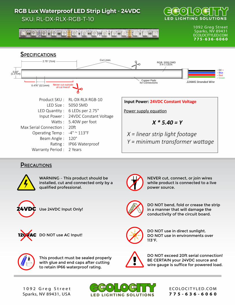
SPECIFICATIONS
PRECAUTIONS
!
24VDC24VDC3M VHB3M VHB3M VHB3M VHB
3M VHB3M VHB3M VHB3M VHB
120VAC
Use 24VDC Input Only!
DO NOT use AC Input!
WARNING – This product should be installed, cut and connected only by a qualified professional.
NEVER cut, connect, or join wires while product is connected to a live power source.
DO NOT bend, fold or crease the strip in a manner that will damage the conductivity of the circuit board.
DO NOT use in direct sunlight.DO NOT use in environments over 113°F.
DO NOT exceed 20ft serial connection!BE CERTAIN your 24VDC source and wire gauge is suffice for powered load.
RTV4500
This product must be sealed properly with glue and end caps after cutting to retain IP66 waterproof rating.
1092 Greg StreetSparks, NV 89431
ECOLOCITYLED.COM775 - 636 - 6060
L E D L I G H T I N G S O L U T I O N S
E C O L O C I T Y L E D . C O M7 7 5 - 6 3 6 - 6 0 6 0
1 0 9 2 G r e g S t r e e tSparks, NV 89431, USA L E D L I G H T I N G S O L U T I O N S
Never cut outsideof cut lines!!
R R
24V+BRG
2.75” (7cm)
Copper Pads for Connections
Cut Lines
0.476” (12.1mm)
0.50”(1.27cm)
RGB, 5050 SMD3 in 1 LEDs
Product SKU :LED Size :
LED Quan�ty :Input Power :
Wa�s :Max Serial Connec�on :
Opera�ng Temp :Beam Angle :
Ra�ng :Warranty Period :
RL-DX-RLX-RGB-105050 SMD6 LEDs per 2.75"24VDC Constant Voltage5.40W per foot20�-4° ~ 113°F120°IP66 Waterproof2 Years
Power supply equa�on
X * 5.40 = Y
X = linear strip light footageY = minimum transformer wattage
Red
DC +
Green
Blue
22AWG Stranded Wire
Input Power: 24VDC Constant Voltage

RGB Lux Waterproof LED Strip Light - 24VDCSKU: RL-DX-RLX-RGB-T-10
INSTALLATION
REQUIRED SUPPLIES OPTIONAL SUPPLIES
Cleaning Suppliesor Degreaser
Stranded Wire andWire Strippers
Wire Nuts orConnectors
24VDC PowerSupply
RGB 3 ChannelColor Controller
LED CONTROLLER
PAUSE
=
MODE-
MODE+
SPEED-
SPEED+
BRT-
BRT+
+_
DC+
DC-
V+
B-
G-
R-
Solder, Solder Iron, Adhesive and End Caps(Required to cut and re-connect)
RTV4500
pg. 2 of 3
1.) Clean Mounting Surface
Use your cleaning supplies to clean your moun�ng surface. Please note that moun�ng surface must be smooth, clean and dry for the 3M tape to permanently adhere.
2.) Connect Transformer
WARNING – This step should be done by a qualified professional. Always disable AC power before connec�ng! Use wire nuts or connectors to secure your AC input to your 24V transformer.
NEUTRALNEUTRALLOAD
GROUND
3.) Connect Controller
Always be certain power is disabled before connec�ng! Use a small screw driver to connect your 24VDC posi�ve and nega�ve wires to your 3 channel RGB controller input.
+_
DC+
DC-
V+
B-
G-
R-
4.) Test and Mount Strips
Always test your strip lights before adhering the 3M double sided tape. Never test the strip light when rolled inside the plas�c reel.
3.) Connect Strip Lights
Always be certain power is disabled before connec�ng! Use a screw driver to connect the 4 wires from your RGB strip light to the proper output ports of your 3 channel RGB controller.
+_
DC+
DC-
V+
B-
G-
R-
12VDC +BGR
12VDC +BGR
12VDC +BGR
+B
GR
+BGR
+BGRE469048
CONNECTION EXAMPLES: 5.4 Watts per foot
118” Strip wired to 24VDC RGB Controller(Use Parallel Connec�ons every 20�)
+_
DC+
DC-
V+
B-
G-
R-
24V+BRG
24V+BRG118” (3m)
24VDCPOWER SUPPLY
T0 110-220VAC
Mul�ple Strips wired to 24VDC RGB Controller(Example of Parallel Connec�on)
+_
DC+
DC-
V+
B-
G-
R-
24V+BRG
24V+BRG
20ft 20ft
24VDCPOWER SUPPLY
T0 110-220VAC
Strips wired to 24VDC RGB Controller & Signal Amp(Use Parallel Connec�ons every 30�)
SIGN
AL IN
BGRV
OU
TPU
T
BGRV
DC
IN12/24V
V+
V-
+_
DC+
DC-
V+
B-
G-
R-
24V+BRG
24V+BRG
24V+BRG
24V+BRG
Use SignalAmp to Extend
Max ControllerLoad
24VDCPOWER SUPPLY
T0 110-220VAC
T0 NEXT 20FT
����� ������ ��� ���������� ��� ������ ������ ���� �� ������� ���� ��� ���� �� ��� ����� ����� ������.
(Use Parallel Connec�ons every 20�)
E C O L O C I T Y L E D . C O M7 7 5 - 6 3 6 - 6 0 6 0
1 0 9 2 G r e g S t r e e tSparks, NV 89431, USA L E D L I G H T I N G S O L U T I O N S

STRIP LIGHT ACCESSORIES:
E C O L O C I T Y L E D . C O M7 7 5 - 6 3 6 - 6 0 6 0
1 0 9 2 G r e g S t r e e tSparks, NV 89431, USA L E D L I G H T I N G S O L U T I O N S
RGB Lux Waterproof LED Strip Light - 24VDCSKU: RL-DX-RLX-RGB-T-10
pg. 3 of 3
RGB WaterproofConnectors
24VDC Power Supplies RGB LED Controllers Aluminum Extrusionsand Covers
24VDC Power Supplies - https://www.ecolocityled.com/category/led_power_supplies_24vRGB LED Controllers - https://www.ecolocityled.com/category/rgb_led_lighting_controllers_onlyRGB Connec�on Wire - https://www.ecolocityled.com/category/led_connection_wire_productsAluminum Extrusions - https://www.ecolocityled.com/category/led_aluminum_extrusionsStrip Light Soldering Guide - https://www.ecolocityled.com/category/led_tutorials_rgb_solder
HELPFUL LINKS:
SOLDERING INSTRUCTION
REQUIRED SUPPLIES
Rosin CoreElectrical Solder
Electrical Soldering Iron(Preferably Temp Adjustable)
Razor Blade orCu�ng Tool
MaskingTape
1.) Cut Waterproof Coating
Cut your strip light to length on the cut line only. Then use a sharp blade or cu�ng tool to expose the copper pads enough for soldering.
+BGR
+
_
360
2.) Tin Strip Light Pads
Heat your soldering iron to 500-600°F. Use a piece of masking tape to secure your strip then �n each copper pad with rosin core electrical solder.
+BGR
+
_
360
4.) Push Wires through Cap
Push your connec�on wires through the end cap with wire holes. Be sure to face the end cap in the right direc�on.
3.) Strip and Tin Wire
Strip your 2 conductor stranded wire roughly 1/8”. Tin the exposed wires with rosin core solder.
6.) Test Connection
Before permanently adhering your end cap to the strip light, it is a good idea to test your connec�on first.
+BRG
+
_
360
8.) Let Glue Set
Our waterproof strip lights have a hollow inside. Be certain to hang the strip ver�cal so that the glue sets inside the moun�ng cap.
+BGR
+_
360
Gravity
Stranded Wire andWire Strippers
Strip LightEnd Caps
5.) Solder Wire to Strip
Mate your �nned wire to the copper pad with respec�ve polarity. Black wire to DC+ (posi�ve), Red wire to (R), Green to (G) and Blue to (B).
+BRG
+
_
360
7.) Glue End Cap
You can now glue on your end cap. We recommend using RTV 4500 Silicone type adhesive, fill the en�re end cap and gum all commisures.
+BRG
+
_
360
RTV4500
SiliconeAdhesive
RTV4500