Embed Size (px)
Citation preview
HMS Industrial Networks AB
GermanyJapanSwedenU.S.A.FranceItalyChina
+ 49 - 721 - 96472 - 0+ 81 - 45 - 478 -5340+ 46 - 35 - 17 29 20+ 1 - 312 - 829 - 0601+ 33 - 3 89 32 76 76+ 39 - 347 - 00894 - 70+ 86 - 10 - 8532 - 3183
[email protected]@[email protected]@[email protected]@[email protected]
X-gateway Interface Addendum
PROFIBUS MasterDoc.Id. SCM-1200-049
Rev. 1.11

Preface About This Document
How To Use This Document ............................................................................................................ P-1
Important User Information .............................................................................................................. P-1
Related Documents.............................................................................................................................. P-2
Document History ............................................................................................................................... P-2
Conventions & Terminology.............................................................................................................. P-3
Support .................................................................................................................................................. P-4
Chapter 1 About the PROFIBUS Master
General Description..............................................................................................................................1-1
Features...................................................................................................................................................1-1
Status LEDs ...........................................................................................................................................1-2
Connectors .............................................................................................................................................1-2
Chapter 2 Data Exchange
General Information.............................................................................................................................2-1
Control & Status Word Implementation Details .............................................................................2-2Status Word .................................................................................................................................2-2Control Word ...............................................................................................................................2-2
Live List Implementation Details .......................................................................................................2-2
Chapter 3 Gateway Config Interface
General Information.............................................................................................................................3-1
Operation Modes ..................................................................................................................................3-1
Configuration Settings ..........................................................................................................................3-1
Chapter 4 PROFIBUS Config Interface
General Information.............................................................................................................................4-1
HMS Transport Provider .....................................................................................................................4-1
Configuration Example ........................................................................................................................4-2
Appendix A Technical Specification
PROFIBUS Interface Pinout .............................................................................................................A-1
PROFIBUS Config Interface Pinout ................................................................................................A-1
Table of Contents
Table of Contents


Preface
About This Document
How To Use This Document
This document describes the various features of the PROFIBUS Master for the X-gateway, basic net-work installation procedures and other network specific details. General information and operating in-structions for the gateway is available in the main User Manual.
The reader of this document is expected to be familiar with the PROFIBUS networking system, and communication systems in general.
For further information, documentation etc., please visit the HMS website, ‘www.anybus.com’.
Important User Information
The data and illustrations found in this document are not binding. We, HMS Industrial Networks AB, reserve the right to modify our products in line with our policy of continuous product development. The information in this document is subject to change without notice and should not be considered as a com-mitment by HMS Industrial Networks AB. HMS Industrial Networks AB assumes no responsibility for any errors that may appear in this document.
There are many applications of this product. Those responsible for the use of this device must ensure that all the necessary steps have been taken to verify that the application meets all performance and safe-ty requirements including any applicable laws, regulations, codes, and standards.
Anybus® is a registered trademark of HMS Industrial Networks AB. All other trademarks are the prop-erty of their respective holders.
The examples and illustrations in this document are included solely for illustrative purposes. Because of the many variables and requirements associated with any particular implementation, HMS Industrial Networks cannot assume responsibility or liability for actual use based on these examples and illustra-tions.
Warning: This is a class A product. In a domestic environment this product may cause radio interfer-ence in which case the user may be required to take adequate measures.
ESD Note: This product contains ESD (Electrostatic Discharge) sensitive parts that may be damaged if ESD control procedures are not followed. Static control precautions are required when handling the product. Failure to observe this may cause damage to the product.
About This Document P-2
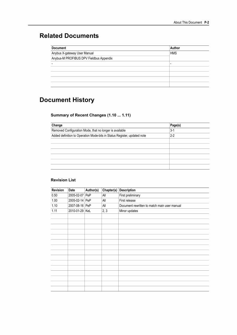
Related Documents
Document History
Summary of Recent Changes (1.10 ... 1.11)
Revision List
Document Author
Anybus X-gateway User Manual HMS
Anybus-M PROFIBUS DPV Fieldbus Appendix
- -
Change Page(s)
Removed Configuration Mode, that no longer is available 3-1
Added definition to Operation Mode-bits in Status Register, updated note 2-2
Revision Date Author(s) Chapter(s) Description
0.50 2005-02-07 PeP All First preliminary
1.00 2005-02-14 PeP All First release
1.10 2007-08-16 PeP All Document rewritten to match main user manual
1.11 2010-01-29 KeL 2, 3 Minor updates

About This Document P-3
Conventions & Terminology
The following conventions are used throughout this manual:
• Numbered lists provide sequential steps
• Bulleted lists provide information, not procedural steps
• The term ‘Master interface’ refers to the PROFIBUS Master interface for the X-gateway
• The term ‘Slave interface’ or ‘other network’ refers to the other, ‘non PROFBUS’-side of the gateway.
• The term ‘user manual’ is used when referring to the Anybus X-gateway User Manual.
• Hexadecimal values are written in the format NNNNh, where NNNN is the hexadecimal value.
About This Document P-4
Support
HMS Sweden (Head Office)
E-mail: [email protected]: +46 (0) 35 - 17 29 20Fax: +46 (0) 35 - 17 29 09Online: www.anybus.com
HMS North America
E-mail: [email protected]: +1-312-829-0601 Toll Free: +1-888-8-AnybusFax: +1-312-738-5873Online: www.anybus.com
HMS Germany
E-mail: [email protected]: +49-721-96472-0Fax: +49-721-964-7210Online: www.anybus.com
HMS Japan
E-mail: [email protected]: +81-45-478-5340Fax: +81-45-476-0315Online: www.anybus.com
HMS China
E-mail: [email protected]: +86 10 8532 3023Online: www.anybus.com
HMS Italy
E-mail: [email protected]: +39 039 59662 27Fax: +39 039 59662 31Online: www.anybus.com
HMS France
E-mail: [email protected]: +33 (0) 3 89 32 76 41Fax: +33 (0) 3 89 32 76 31Online: www.anybus.com
Chapter 1
About the PROFIBUS Master
General Description
The PROFIBUS Master interface for the Anybus X-gateway allows up to 125 PROFIBUS slaves to ex-change data with another network.
The interface features an on-board configuration interface, which is used to interface the master with the Anybus NetTool for PROFIBUS configuration software.
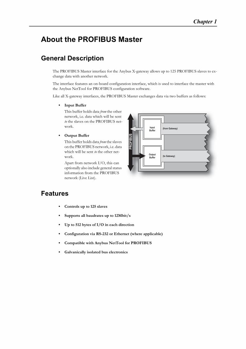
Like all X-gateway interfaces, the PROFIBUS Master exchanges data via two buffers as follows:
• Input Buffer
This buffer holds data from the other network, i.e. data which will be sent to the slaves on the PROFIBUS net-work.
• Output Buffer
This buffer holds data from the slaves on the PROFIBUS network, i.e. data which will be sent to the other net-work.
Apart from network I/O, this can optionally also include general status information from the PROFIBUS network (Live List).
Features
• Controls up to 125 slaves
• Supports all baudrates up to 12Mbit/s
• Up to 512 bytes of I/O in each direction
• Configuration via RS-232 or Ethernet (where applicable)
• Compatible with Anybus NetTool for PROFIBUS
• Galvanically isolated bus electronics
PROF
IBUS
OutputBuffer (to Gateway)
InputBuffer
(from Gateway)
About the PROFIBUS Master 1-2
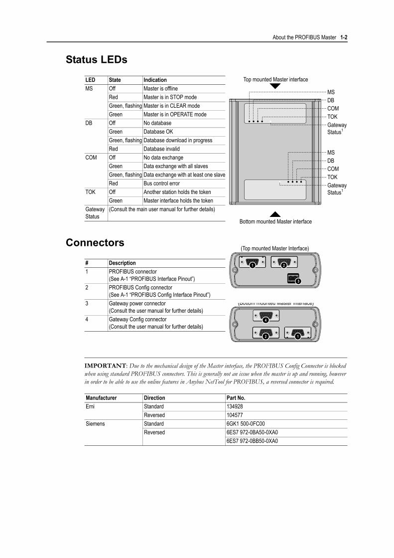
Status LEDs
Connectors
IMPORTANT: Due to the mechanical design of the Master interface, the PROFIBUS Config Connector is blocked when using standard PROFIBUS connectors. This is generally not an issue when the master is up and running, however in order to be able to use the online features in Anybus NetTool for PROFIBUS, a reversed connector is required.
LED State Indication
MS Off Master is offline
Red Master is in STOP mode
Green, flashing Master is in CLEAR mode
Green Master is in OPERATE mode
DB Off No database
Green Database OK
Green, flashing Database download in progress
Red Database invalid
COM Off No data exchange
Green Data exchange with all slaves
Green, flashing Data exchange with at least one slave
Red Bus control error
TOK Off Another station holds the token
Green Master interface holds the token
Gateway Status
(Consult the main user manual for further details)
# Description
1 PROFIBUS connector(See A-1 “PROFIBUS Interface Pinout”)
2 PROFIBUS Config connector(See A-1 “PROFIBUS Config Interface Pinout”)
3 Gateway power connector(Consult the user manual for further details)
4 Gateway Config connector(Consult the user manual for further details)
Manufacturer Direction Part No.
Erni Standard 134928
Reversed 104577
Siemens Standard 6GK1 500-0FC00
Reversed 6ES7 972-0BA50-0XA0
6ES7 972-0BB50-0XA0
4
2 1
(Bottom mounted Master Interface)
COMTOKGateway Status1
Gateway Status1
DBMS
COMTOK
DBMS
Top mounted Master interface
Bottom mounted Master interface
21
3
(Top mounted Master Interface)
Chapter 2
Data Exchange
General Information
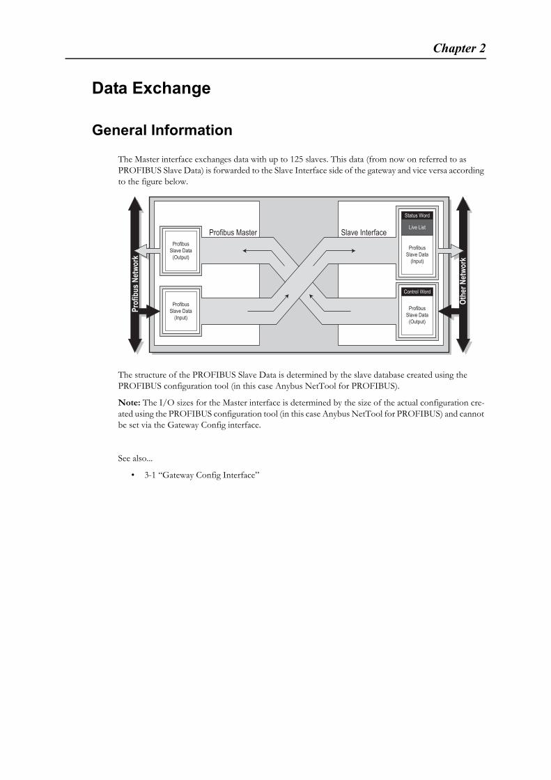
The Master interface exchanges data with up to 125 slaves. This data (from now on referred to as PROFIBUS Slave Data) is forwarded to the Slave Interface side of the gateway and vice versa according to the figure below.
The structure of the PROFIBUS Slave Data is determined by the slave database created using the PROFIBUS configuration tool (in this case Anybus NetTool for PROFIBUS).
Note: The I/O sizes for the Master interface is determined by the size of the actual configuration cre-ated using the PROFIBUS configuration tool (in this case Anybus NetTool for PROFIBUS) and cannot be set via the Gateway Config interface.
See also...
• 3-1 “Gateway Config Interface”
Slave InterfaceProfibus Master
Othe
rNet
work
Status Word
Live List
Control Word
Prof
ibus
Netw
ork
ProfibusSlave Data
(Output)Profibus
Slave Data(Input)
ProfibusSlave Data
(Output)
ProfibusSlave Data
(Input)
Data Exchange 2-2
Control & Status Word Implementation Details
Status Word
The Status Word holds general status information from the gateway.
(Consult the user manual for further information).
Control Word
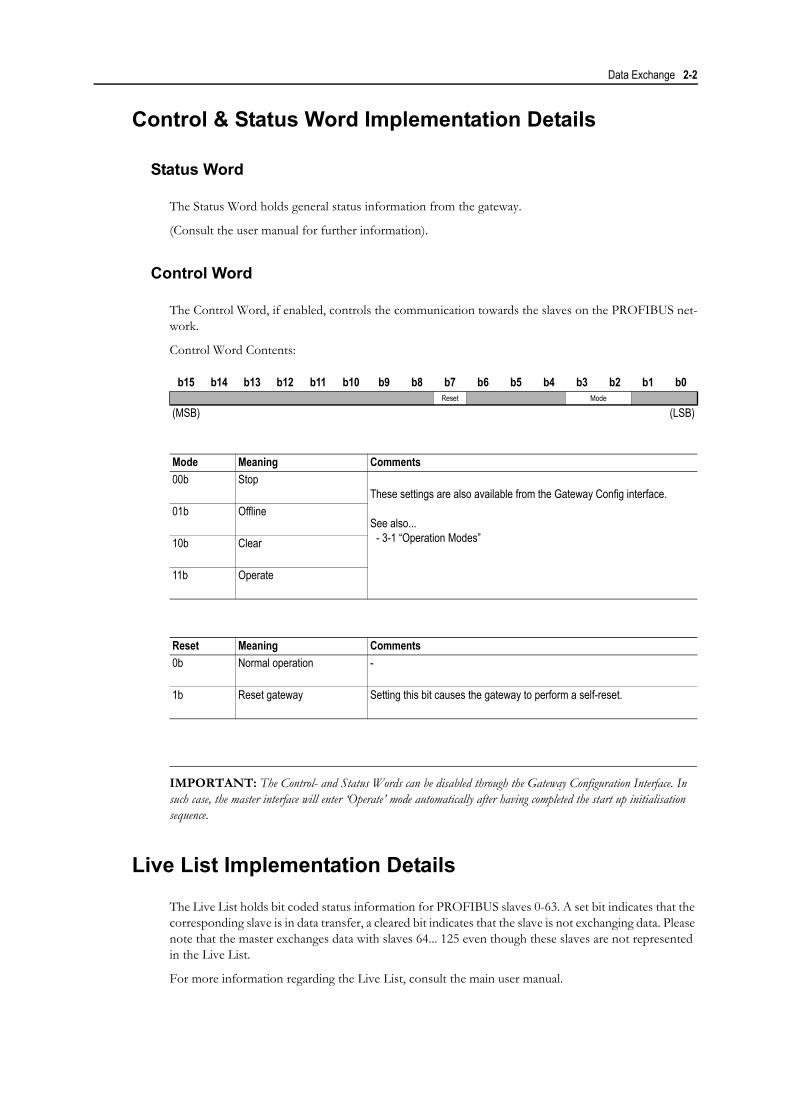
The Control Word, if enabled, controls the communication towards the slaves on the PROFIBUS net-work.
Control Word Contents:
IMPORTANT: The Control- and Status Words can be disabled through the Gateway Configuration Interface. In such case, the master interface will enter ‘Operate’ mode automatically after having completed the start up initialisation sequence.
Live List Implementation Details
The Live List holds bit coded status information for PROFIBUS slaves 0-63. A set bit indicates that the corresponding slave is in data transfer, a cleared bit indicates that the slave is not exchanging data. Please note that the master exchanges data with slaves 64... 125 even though these slaves are not represented in the Live List.
For more information regarding the Live List, consult the main user manual.
b15 b14 b13 b12 b11 b10 b9 b8 b7 b6 b5 b4 b3 b2 b1 b0Reset Mode
(MSB) (LSB)
Mode Meaning Comments
00b StopThese settings are also available from the Gateway Config interface.
See also...- 3-1 “Operation Modes”
01b Offline
10b Clear
11b Operate
Reset Meaning Comments
0b Normal operation -
1b Reset gateway Setting this bit causes the gateway to perform a self-reset.
Chapter 3
Gateway Config Interface
General Information
The Gateway Config Interface features certain settings specific to the PROFIBUS master interface.
(Consult the user manual for further information about the Gateway Config Interface).
Operation Modes
The main menu features an additional entry called ‘Change operation mode’, which affects the commu-nication towards the slaves on the PROFIBUS network.
The master features the following Operation Modes:
Note: This setting is not available when the Control/Status words are enabled on the slave side of the gateway.
See also...
• 2-2 “Control & Status Word Implementation Details”
Configuration Settings
The master features the following PROFIBUS master specific configuration settings:
Note: It is not possible to set the I/O sizes for the master in this menu since this information is deter-mined automatically based on the actual slave database.
See also...
• 2-2 “Live List Implementation Details”
• 4-1 “PROFIBUS Config Interface”
Operation Mode Description
Stop -
Clear -
Operate -
Setting Description
Live List This setting enables/disables the Live List.
Chapter 4
PROFIBUS Config Interface
General Information
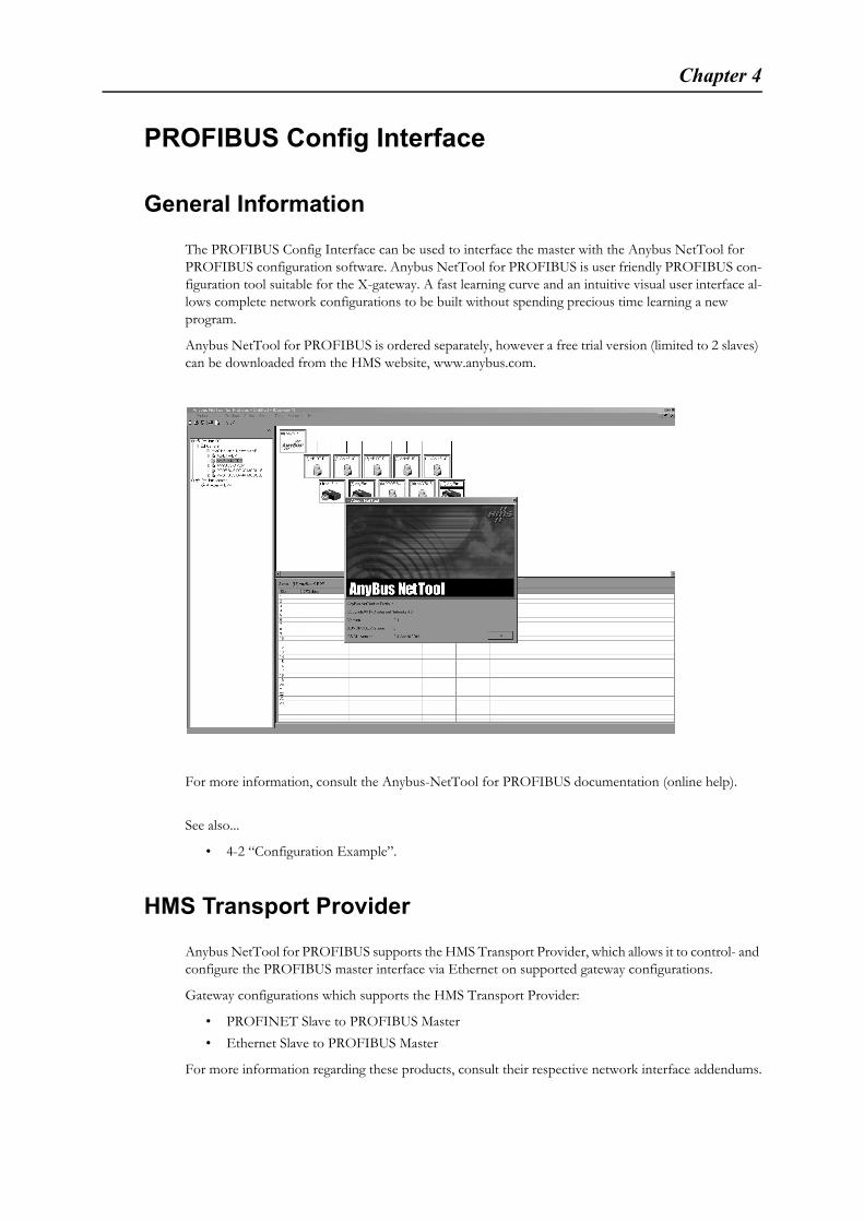
The PROFIBUS Config Interface can be used to interface the master with the Anybus NetTool for PROFIBUS configuration software. Anybus NetTool for PROFIBUS is user friendly PROFIBUS con-figuration tool suitable for the X-gateway. A fast learning curve and an intuitive visual user interface al-lows complete network configurations to be built without spending precious time learning a new program.
Anybus NetTool for PROFIBUS is ordered separately, however a free trial version (limited to 2 slaves) can be downloaded from the HMS website, www.anybus.com.
For more information, consult the Anybus-NetTool for PROFIBUS documentation (online help).
See also...
• 4-2 “Configuration Example”.
HMS Transport Provider
Anybus NetTool for PROFIBUS supports the HMS Transport Provider, which allows it to control- and configure the PROFIBUS master interface via Ethernet on supported gateway configurations.
Gateway configurations which supports the HMS Transport Provider:
• PROFINET Slave to PROFIBUS Master
• Ethernet Slave to PROFIBUS Master
For more information regarding these products, consult their respective network interface addendums.
PROFIBUS Config Interface 4-2
Configuration Example
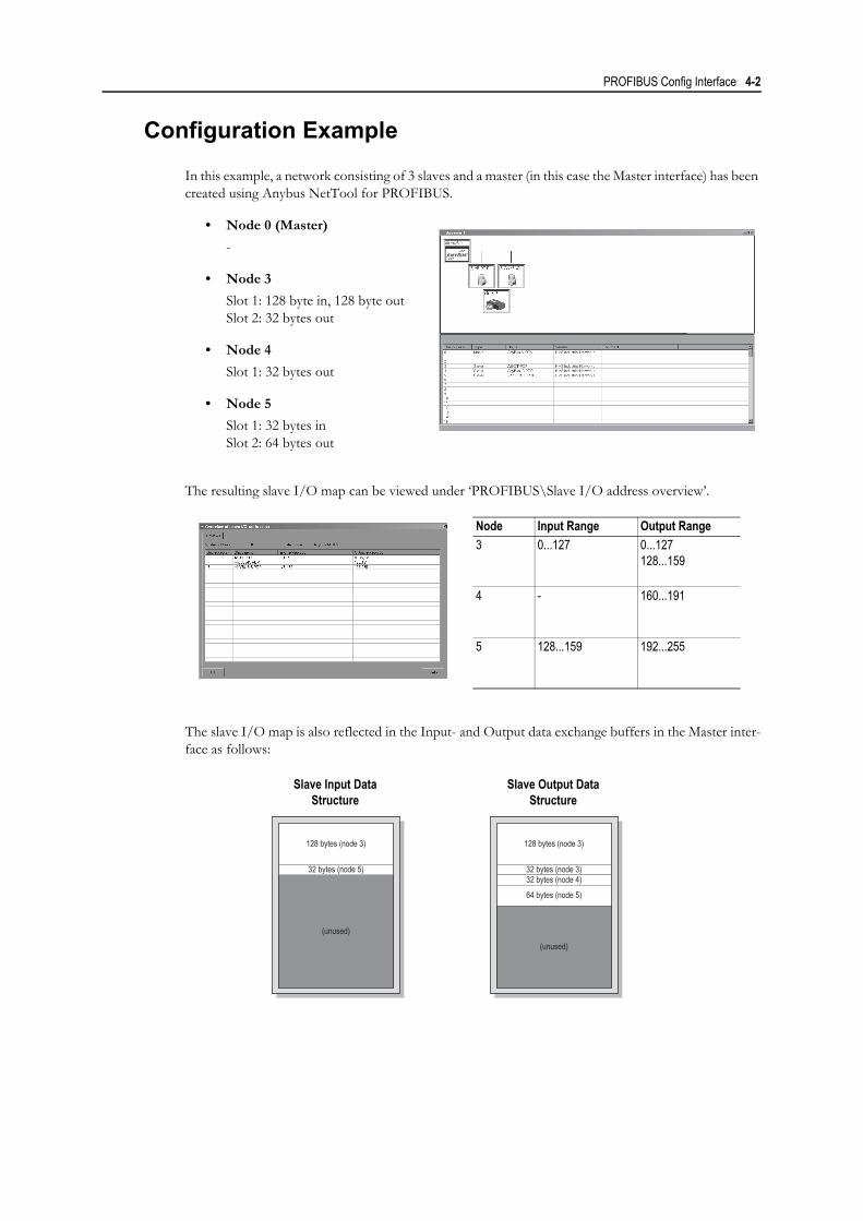
In this example, a network consisting of 3 slaves and a master (in this case the Master interface) has been created using Anybus NetTool for PROFIBUS.
• Node 0 (Master)
-
• Node 3
Slot 1: 128 byte in, 128 byte outSlot 2: 32 bytes out
• Node 4
Slot 1: 32 bytes out
• Node 5
Slot 1: 32 bytes inSlot 2: 64 bytes out
The resulting slave I/O map can be viewed under ‘PROFIBUS\Slave I/O address overview’.
The slave I/O map is also reflected in the Input- and Output data exchange buffers in the Master inter-face as follows:
Node Input Range Output Range
3 0...127 0...127128...159
4 - 160...191
5 128...159 192...255
Slave Input Data Structure
Slave Output DataStructure
128 bytes (node 3)
(unused)
32 bytes (node 5)
128 bytes (node 3)
(unused)
32 bytes (node 3)32 bytes (node 4)
64 bytes (node 5)
Appendix A
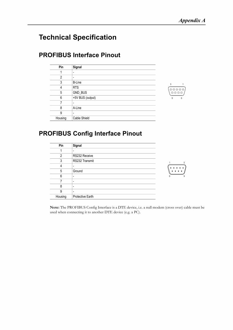
Technical Specification
PROFIBUS Interface Pinout
PROFIBUS Config Interface Pinout
Note: The PROFIBUS Config Interface is a DTE device, i.e. a null modem (cross over) cable must be used when connecting it to another DTE device (e.g. a PC).
Pin Signal
1 -
2 -
3 B-Line
4 RTS
5 GND_BUS
6 +5V BUS (output)
7 -
8 A-Line
9 -
Housing Cable Shield
Pin Signal
1 -
2 RS232 Receive
3 RS232 Transmit
4 -
5 Ground
6 -
7 -
8 -
9 -
Housing Protective Earth
9 6
15
1 5
96