Embed Size (px)
Citation preview
Rev. 2.0 Copyright ©2009 by Auden Techno Corp. WWAN Antenna
No Perfect Status, Always Seek For Better.
WWAN Antenna Datasheet
Description
The exciting Auden antenna is one of the world’s high-performance WWAN
antennas. It is very suitable for WWAN system application with assemble in a suitable
clearance area and collocate with a suitable matching circuit. This WWAN standard
antenna was design to speed the overall development process and decrease required
development time then make your products fast to enter the market of the world. The
dimension is 22.2mm (L) x 7.2mm (W) x 2.55mm (T).
The patent number
Patent pending.
Features
Linear Polarization◎
◎ Standard Antenna
◎ SMD Solder
Ultra◎ -Thin, Light Weight (0.7g)
◎Miniaturized Size (22.2 x 7.2x 2.55mm3)
Omni◎ -Direction Antenna Pattern
◎Wide Bandwidth
Favorable Linear Polarization◎
Cost◎ -Effective
Applications
◎ Mobile phone
◎ USB dongle card
◎ Note book
◎ Smart phone
◎ Tracking device
Pin Assignments
M-PB-0912-CH
Rev. 2.0 Auden Techno Corp. 2
Table OF Contents
Section page
1. Antenna equivalent circuit…..……………………………………..3
2. Pin descriptions…..…………………………………………………4
3. Reel Taping specification…..……………………………………….5
4. Package and form information…..………………………………...6
5. WWAN antenna PCB land pattern………...…………………….7
6. Antenna performance…..…………………………………………..8
Acknowledgement…...............................................................................14
Contact information.…….…………………………………………….14
M-PB-0912-CH
Rev. 2.0 Auden Techno Corp. 3
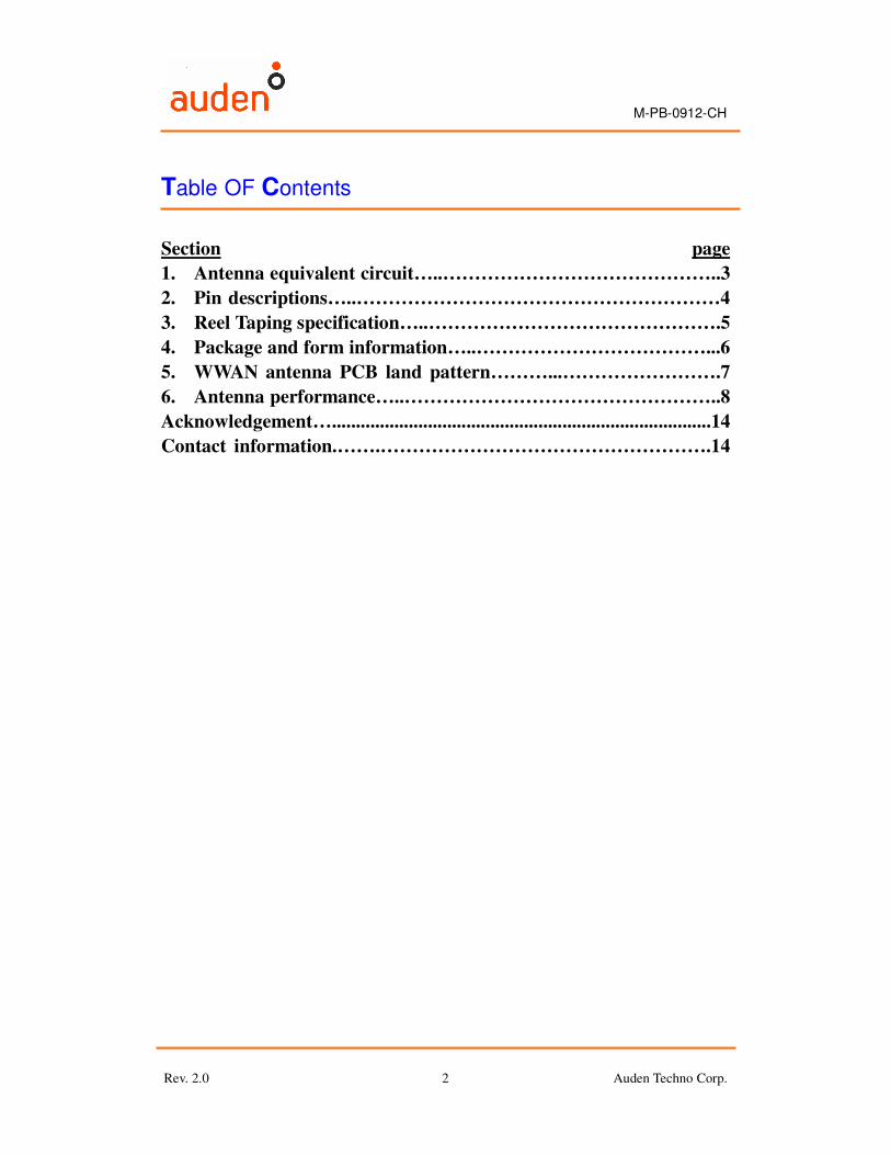
1. Antenna Equivalent Circuit
Fig.1 The Antenna Equivalent Circuit
Table.1 The WWAN Antenna Quick Reference Data
Antenna Type Monopole Antenna
Frequency WWAN(850/900/1800/1900/WCDMA)
Impedance 50ΩΩΩΩ
Polarization Linear
Pattern Omni-Directional
M-PB-0912-CH
Rev. 2.0 Auden Techno Corp. 4
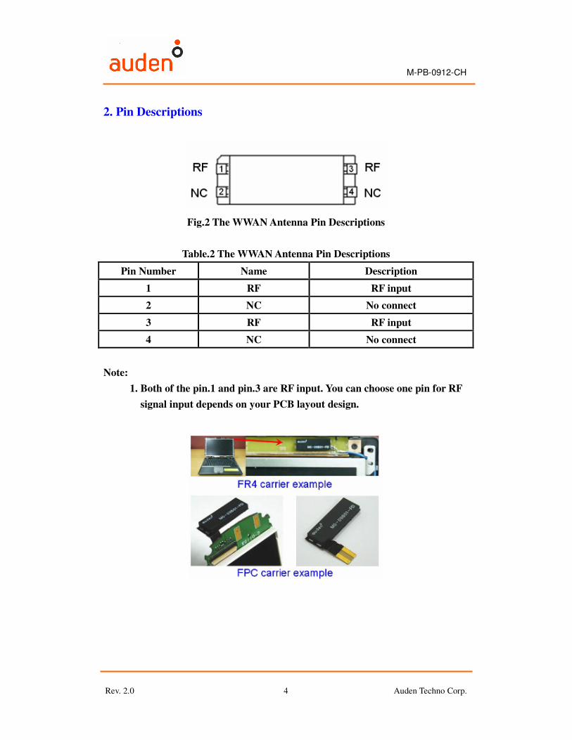
2. Pin Descriptions
Fig.2 The WWAN Antenna Pin Descriptions
Table.2 The WWAN Antenna Pin Descriptions
Pin Number Name Description
1 RF RF input
2 NC No connect
3 RF RF input
4 NC No connect
Note:
1. Both of the pin.1 and pin.3 are RF input. You can choose one pin for RF
signal input depends on your PCB layout design.
M-PB-0912-CH
Rev. 2.0 Auden Techno Corp. 5
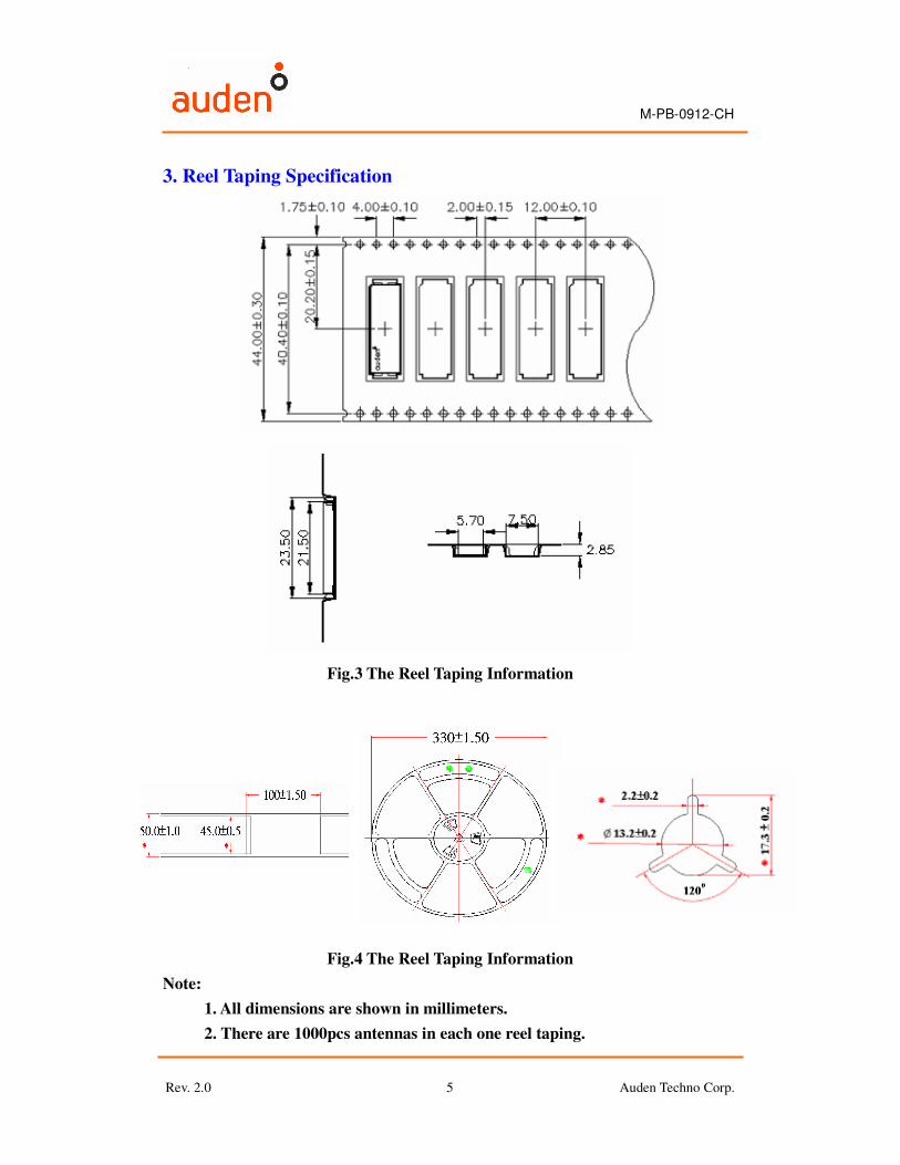
3. Reel Taping Specification
Fig.3 The Reel Taping Information
Fig.4 The Reel Taping Information
Note:
1. All dimensions are shown in millimeters.
2. There are 1000pcs antennas in each one reel taping.
M-PB-0912-CH
Rev. 2.0 Auden Techno Corp. 6
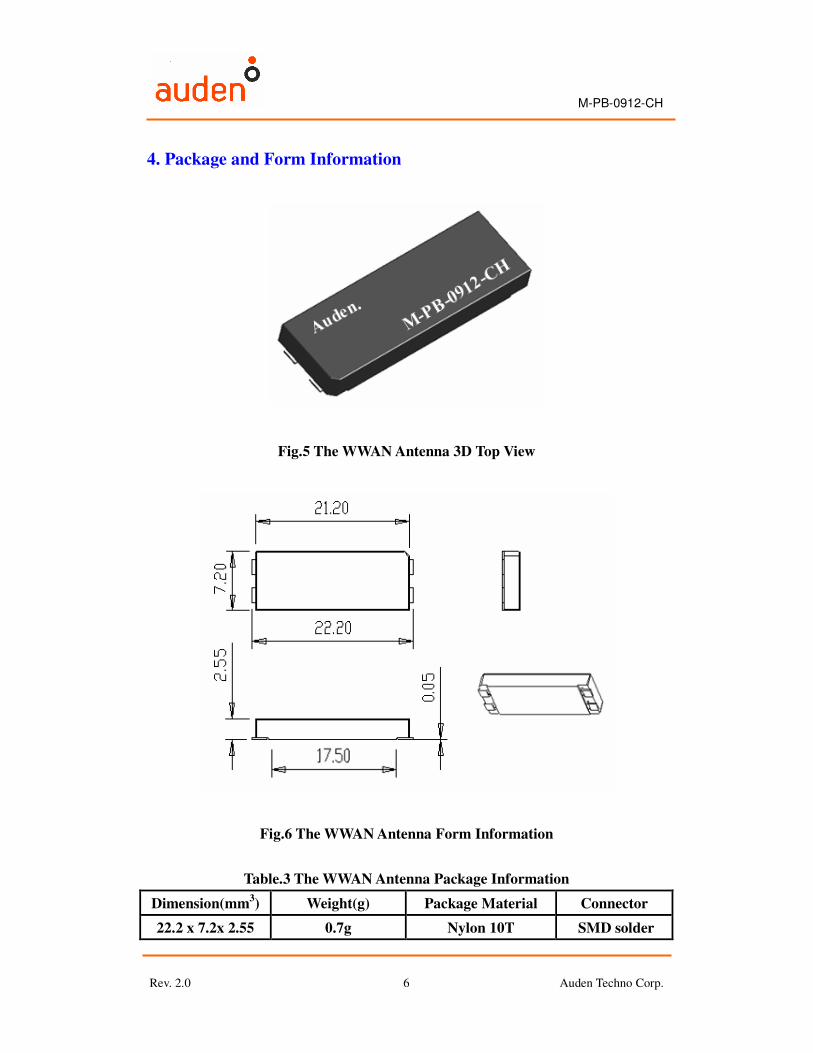
4. Package and Form Information
Fig.5 The WWAN Antenna 3D Top View
Fig.6 The WWAN Antenna Form Information
Table.3 The WWAN Antenna Package Information
Dimension(mm3) Weight(g) Package Material Connector
22.2 x 7.2x 2.55 0.7g Nylon 10T SMD solder
M-PB-0912-CH
Rev. 2.0 Auden Techno Corp. 7
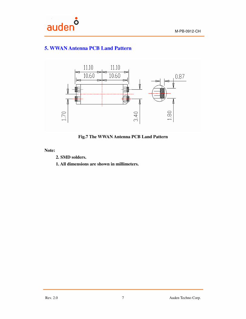
5. WWAN Antenna PCB Land Pattern
Fig.7 The WWAN Antenna PCB Land Pattern
Note:
2. SMD solders.
1. All dimensions are shown in millimeters.
M-PB-0912-CH
Rev. 2.0 Auden Techno Corp. 8
6. Antenna Performance
The antenna efficiency test was by ATL (A Test Lab Techno Corp.). It
measurements were taken in the ETS-Lindgren AMS-8500 standards system
anechoic chamber. The chamber size is 7m x 4m x 4m and supports test
frequencies from 700MHz to 6GHz.
The S11 and VSWR measurements were taken with use Agilent E5071B
network analyzer. The testing was performed in free space.
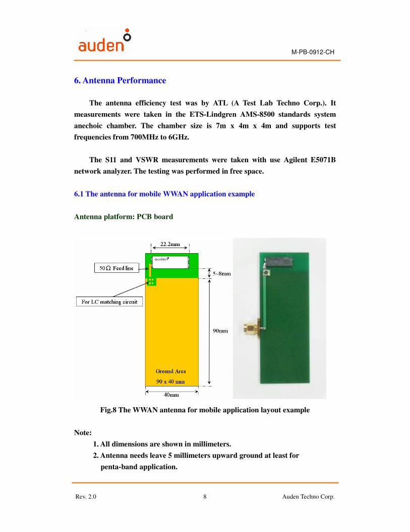
6.1 The antenna for mobile WWAN application example
Antenna platform: PCB board
Fig.8 The WWAN antenna for mobile application layout example
Note:
1. All dimensions are shown in millimeters.
2. Antenna needs leave 5 millimeters upward ground at least for
penta-band application.
M-PB-0912-CH
Rev. 2.0 Auden Techno Corp. 9
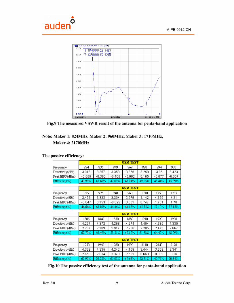
Fig.9 The measured VSWR result of the antenna for penta-band application
Note: Maker 1: 824MHz, Maker 2: 960MHz, Maker 3: 1710MHz,
Maker 4: 2170MHz
The passive efficiency:
Fig.10 The passive efficiency test of the antenna for penta-band application
M-PB-0912-CH
Rev. 2.0 Auden Techno Corp. 10
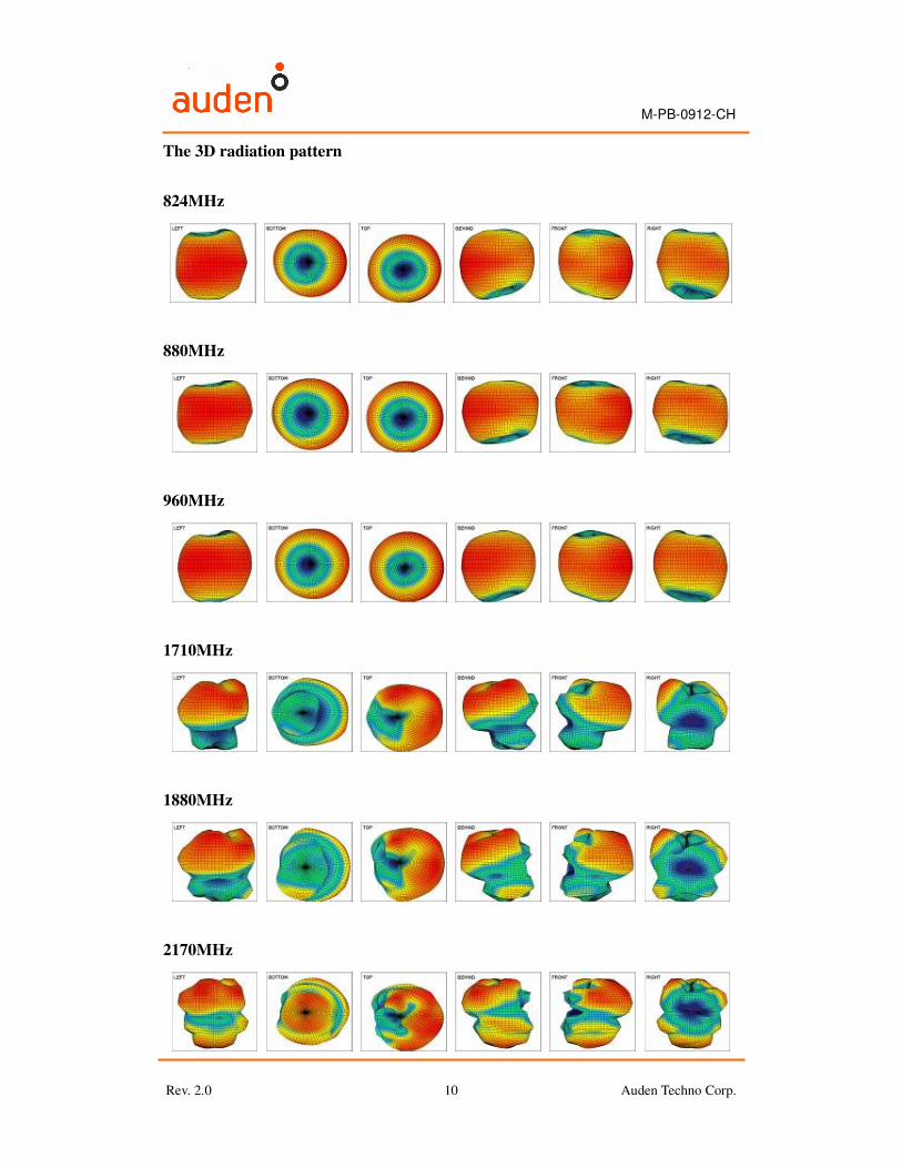
The 3D radiation pattern
824MHz
880MHz
960MHz
1710MHz
1880MHz
2170MHz
M-PB-0912-CH
Rev. 2.0 Auden Techno Corp. 11
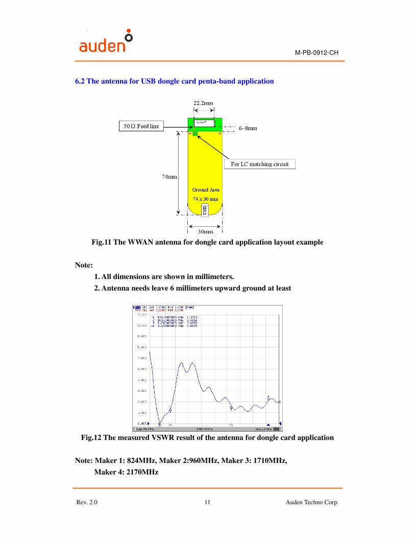
6.2 The antenna for USB dongle card penta-band application
Fig.11 The WWAN antenna for dongle card application layout example
Note:
1. All dimensions are shown in millimeters.
2. Antenna needs leave 6 millimeters upward ground at least
Fig.12 The measured VSWR result of the antenna for dongle card application
Note: Maker 1: 824MHz, Maker 2:960MHz, Maker 3: 1710MHz,
Maker 4: 2170MHz
M-PB-0912-CH
Rev. 2.0 Auden Techno Corp. 12
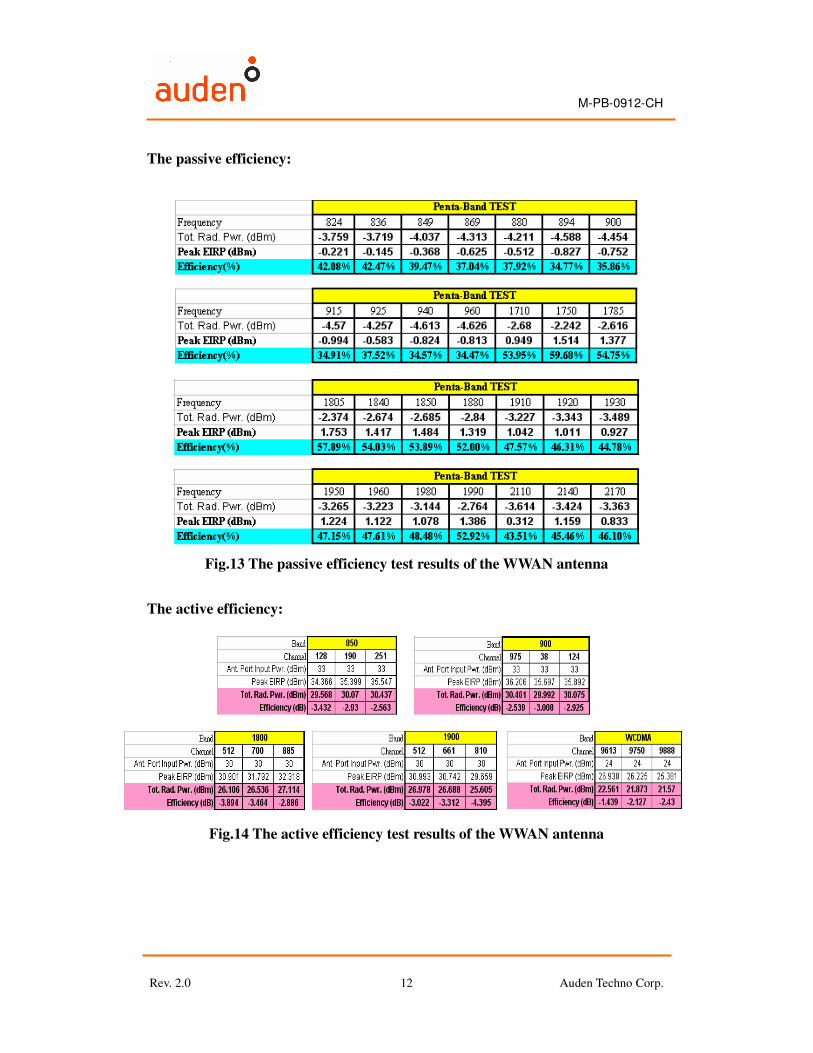
The passive efficiency:
Fig.13 The passive efficiency test results of the WWAN antenna
The active efficiency:
Fig.14 The active efficiency test results of the WWAN antenna
M-PB-0912-CH
Rev. 2.0 Auden Techno Corp. 13
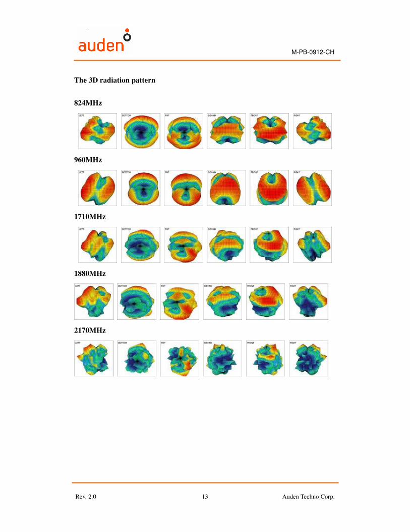
The 3D radiation pattern
824MHz
960MHz
1710MHz
1880MHz
2170MHz
M-PB-0912-CH
Rev. 2.0 Auden Techno Corp. 14
Acknowledgement
Thank you for purchasing the Auden WWAN Antenna. The antenna had
been design to speed the overall development process and decrease required
development time. We look forward to working with you and helping your
products to enter the market of the world.
Contact Information
Please contact us by the below information if you need any solution of the
WWAN antenna.
Auden Techno Corp.
���� E-Mail: [email protected]
���� Tel: 886-3-3631901
���� FAX: 886-3-3660919
���� URL: http://www.auden.com.tw
����Address: 19 Lane 772 Ho-Ping Rd. Pa-Te City Taoyuan Hsien, Taiwan R.O.C