Embed Size (px)
Citation preview
(Lens : option)
Before attempting to connect or operate this product,please read these instructions completely.
CCTV Cameras
WV-BP330/WV-BP332/WV-BP334
ENGL
ISH
DEUT
SCH
FRAN
ÇAIS
ESPA
ÑOL
CAUTIONRISK OF ELECTRIC SHOCK
DO NOT OPEN
CAUTION: TO REDUCE THE RISK OF ELECTRICSHOCK, DO NOT REMOVE COVER (ORBACK), NO USER SERVICEABLE PARTSINSIDE.REFER SERVICING TO QUALIFIED SERVICEPERSONNEL.
The exclamation point within an equilat-eral triangle is intended to alert the userto the presence of important operatingand maintenance (servicing) instruc-tions in the literature accompanying theappliance.
WARNING:TO PREVENT FIRE OR ELECTRIC SHOCK HAZARD, DO NOT EXPOSE THIS APPLIANCE TO RAIN OR MOISTURE.
The lightning flash with arrowhead sym-bol, within an equilateral triangle, isinterned to alert the user to the pres-ence of uninsulated "dangerous volt-age" within the product's enclosure thatmay be of sufficient magnitude to con-stitute a risk of electric shock to per-sons.
ENGLISH VERSION
Wij verklaren als enige aansprakelijke, dat het product waaropdeze verklaring betrekking heeft, voldoet aan de volgende nor-men of andere normatiefve dokumenten, overeenkomstig debepalingen van Richtlijnen 73/23/EEC en 89/336/EEC.
Vi erklærer os eneansvarlige for, at dette produkt, som dennedeklaration omhandler, er i overensstemmelse med denfølgende standarder eller andre normative dokumenter i følgebestemmelserne i direktivene 73/23/EEC og 89/336/EEC.
Vi deklarerar härmed värt fulla ansvar för att den produkt tillvilken denna deklaration hänvisar är i överensstämmelse medstandarddokument, eller andra normativa dokument somframstölls i Direktiv 73/23/EEC och 89/336/EEC.
Ilmoitamme yksinomaisella vastuullamme, että tuote, jota tämäilmoitus koskee, noudattaa seuraavia standardeja tai muitaohjeellisia asiakirjoja, jotka noudattavat direktiivien 73/23/EECia 89/336/EEC. säädöksiä.
Vi erklærer oss alene ansvarlige for at produktet som denneerklæringen gjelder for, er i overensstemmelse med følgendenormer eller andre normgivende dokumenter som fælgerbestemmelsene i direktiven 73/23/EEC og 89/336/EEC.
We declare under our sole responsibility that the product towhich this declaration relates is in conformity with the stan-dards or other normative documents following the provisions ofDirectives EEC/73/23 and EEC/89/336.
Noi dichiariamo sotto nostra esclusiva responsabilità che ilprodotto a cui si riferisce la presente dichiarazione risulta con-forme ai seguenti standard o altri documenti normativi conformialle disposizioni delle direttive CEE/73/23 e CEE/89/336.
FOR YOUR SAFETY PLEASE READ THE FOLLOWING TEXT CARE-FULLY.This appliance is supplied with a moulded three pin mains plug for yoursafety and convenience.A 13 amp fuse is fitted in this plug.Should the fuse need to be replaced please ensure that the replacementfuse has a rating of 13 amp and that it is approved by ASTA or BSI toBS1362.Check for the ASTA mark H or the BSI mark G on the body of the fuse.If the plug contains a removable fuse cover you must ensure that it is refit-ted when the fuse is replaced.If you lose the fuse cover the plug must not be used until a replacementcover is obtained.A replacement fuse cover can be purchased from your local PanasonicDealer.
IF THE FITTED MOULDED PLUG IS UNSUITABLE FOR THE SOCKETOUTLET IN YOUR HOME THEN THE FUSE SHOULD BE REMOVEDAND THE PLUG CUT OFF AND DISPOSED OF SAFELY.THERE IS A DANGER OF SEVERE ELECTRICAL SHOCK IF THE CUTOFF PLUG IS INSERTED INTO ANY 13 AMP SOCKET.
If a new plug is to be fitted please observe the wiring code as shown below.If in any doubt please consult a qualified electrician.WARNING: This apparatus must be earthed.
ENGL
ISH
-1-
The serial number of this product may be found on the topof the unit.You should note the serial number of this unit in the spaceprovided and retain this book as a permanent record ofyour purchase to aid identification in the event of theft.
Model No.
Serial No.
For U.K.
IMPORTANT
The wires in this mains lead are coloured in accordance with the followingcode.
Green-and-yellow: EarthBlue: NeutralBrown: Live
As the colours of the wire in the mains lead of this appliance may notcorrespond with the coloured markings identifying the terminals in yourplug, proceed as follows.
The wire which is coloured green-and-yellow must be connected tothe terminal in the plug which is marked with the letter E or by the earthsymbol I or coloured green or green-and-yellow.
The wire which is coloured blue must be connected to the terminal inthe plug which is marked with the letter N or coloured black.
The wire which is coloured brown must be connected to the terminalin the plug which is marked with the letter L or coloured red.
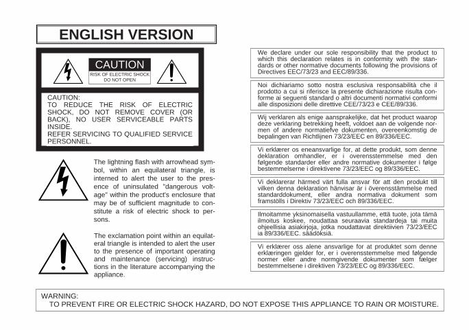
How to replace the fuseOpen the fuse compartment witha screwdriver and replace the fuseand fuse cover.
FUSE
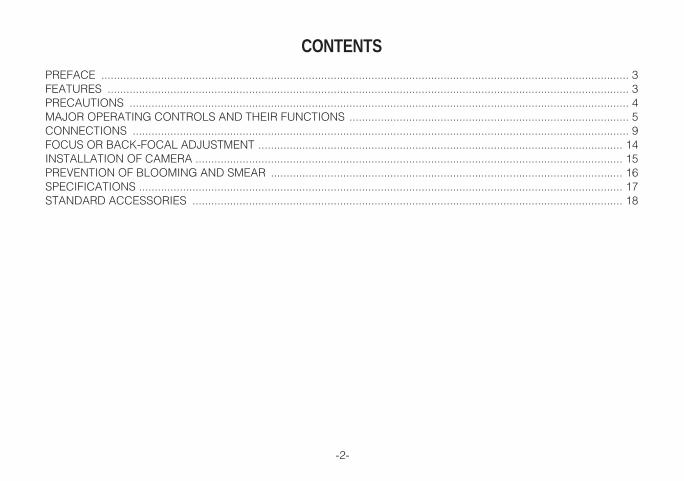
CONTENTSPREFACE ........................................................................................................................................................................ 3FEATURES ...................................................................................................................................................................... 3PRECAUTIONS ............................................................................................................................................................... 4MAJOR OPERATING CONTROLS AND THEIR FUNCTIONS ......................................................................................... 5CONNECTIONS .............................................................................................................................................................. 9FOCUS OR BACK-FOCAL ADJUSTMENT .................................................................................................................... 14INSTALLATION OF CAMERA ........................................................................................................................................ 15PREVENTION OF BLOOMING AND SMEAR ................................................................................................................ 16SPECIFICATIONS .......................................................................................................................................................... 17STANDARD ACCESSORIES ......................................................................................................................................... 18
-2-
-3-
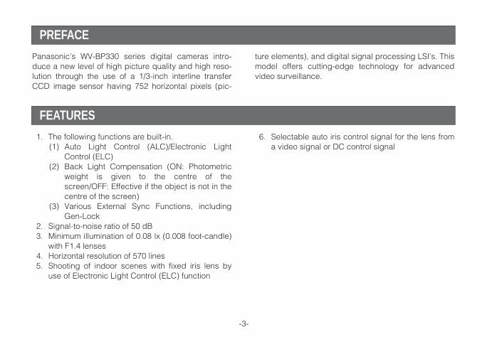
1. The following functions are built-in.(1) Auto Light Control (ALC)/Electronic Light
Control (ELC)(2) Back Light Compensation (ON: Photometric
weight is given to the centre of thescreen/OFF: Effective if the object is not in thecentre of the screen)
(3) Various External Sync Functions, includingGen-Lock
2. Signal-to-noise ratio of 50 dB3. Minimum illumination of 0.08 lx (0.008 foot-candle)
with F1.4 lenses4. Horizontal resolution of 570 lines5. Shooting of indoor scenes with fixed iris lens by
use of Electronic Light Control (ELC) function
ture elements), and digital signal processing LSI’s. Thismodel offers cutting-edge technology for advancedvideo surveillance.
PREFACE
Panasonic’s WV-BP330 series digital cameras intro-duce a new level of high picture quality and high reso-lution through the use of a 1/3-inch interline transferCCD image sensor having 752 horizontal pixels (pic-
FEATURES
6. Selectable auto iris control signal for the lens froma video signal or DC control signal
-4-
1. Do not attempt to disassemble the camera.To prevent electric shock, do not remove screwsor covers.There are no user serviceable parts inside. Ask aqualified service person for servicing.
2. Handle the camera with care.Do not abuse the camera. Avoid striking, shaking,etc. The camera could be damaged by improperhandling or storage.
3. Do not expose the camera to rain or moisture,or try to operate it in wet areas.Turn the power off immediately and ask a qualifiedservice person for servicing. Moisture can damagethe camera and also create the danger of electricshock.
4. Do not use strong or abrasive detergents whencleaning the camera body.Use a dry cloth to clean the camera when dirty.In case the dirt is hard to remove, use a milddetergent and wipe gently.
5. Clean the CCD faceplate with care.Do not clean the CCD with strong or abrasivedetergents. Use lens tissue or a cotton tippedapplicator and ethanol.
6. Never face the camera towards the sun.Do not aim the camera at bright objects. Whetherthe camera is in use or not, never aim it at the sunor other extremely bright objects. Otherwise,blooming or smear may be caused.
7. Do not operate the camera beyond thespecified temperature, humidity or powersource ratings.Use the camera under conditions where tempera-ture is between –10°C - +50°C (14°F - 122°F), andhumidity is below 90%. The input power source is220-240V AC 50Hz for WV-BP330, 12V DC for WV-BP332, and 24V AC 50Hz for WV-BP334.
PRECAUTIONS
-5-
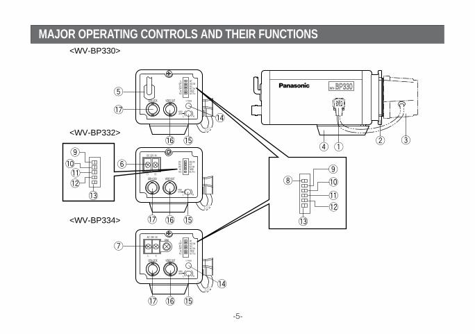
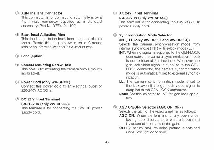
MAJOR OPERATING CONTROLS AND THEIR FUNCTIONS
WV-BP330VIDEO OUTGEN-LOCK
L
INTAGC ONALCBLC ONVIDEOG/L 75
VIDEOLEVEL
V. PHASE
H
Ω
LLOFFELCOFFDC
Hi-Z
GNDAC 24V IN
1 2
VIDEO OUTGEN-LOCK
L
INTAGC ONALCBLC ONVIDEOG/L 75
VIDEOLEVEL
V. PHASE
H
Ω
LLOFFELCOFFDC
Hi-Z
DC 12V IN
VIDEO OUTGEN-LOCK
L
AGC ONALCBLC ONVIDEOG/L 75
VIDEOLEVEL
H
Ω
OFF ELCOFFDC
Hi-Z
<WV-BP330>
<WV-BP332>
<WV-BP334>
-6-
q Auto Iris lens ConnectorThis connector is for connecting auto iris lens by a4-pin male connector supplied as a standardaccessory (Part No. YFE4191J100).
w Back-focal Adjusting RingThis ring is adjusts the back-focal length or picturefocus. Rotate this ring clockwise for a C-mountlens or counterclockwise for a CS-mount lens.
e Lens (option)
r Camera Mounting Screw HoleThis hole is for mounting the camera onto a mount-ing bracket.
t Power Cord (only WV-BP330)Connect this power cord to an electrical outlet of220-240V AC 50Hz.
y DC 12 V Input Terminal (DC 12V IN (only WV-BP332))This terminal is for connecting the 12V DC powersupply cord.
u AC 24V Input Terminal (AC 24V IN (only WV-BP334))This terminal is for connecting the 24V AC 50Hzpower supply cord.
i Synchronization Mode Selector (INT, LL (only WV-BP330 and WV-BP334))Selects the camera synchronization mode frominternal sync mode (INT) or line-lock mode (LL).INT: When no signal is supplied to the GEN-LOCK
connector, the camera synchronization modeis set to internal 2:1 interlace. Whenever thegen-lock video signal is supplied to the GEN-LOCK connector, the camera synchronizationmode is automatically set to external synchro-nization.
LL: The camera synchronization mode is set toline-lock even if the gen-lock video signal issupplied to the GEN-LOCK connector.
Note: Set this selector to INT for gen-lock opera-tion.
o AGC ON/OFF Selector (AGC ON, OFF)Selects the gain of the video amplifier as follows:AGC ON: When the lens iris is fully open under
low light condition, a clear picture is obtainedby automatic increase of the gain.
OFF: A natural and low-noise picture is obtainedunder low light conditions.
-7-
!0 Automatic Light Control / Electronic LightControl Selector (ALC , ELC)Lets you select the mode according to the lenstype that is used with this camera.ALC: Select this mode when an auto iris lens (ALC
lens) is used with this camera.ELC: Select this mode when a fixed iris lens or
manual iris lens is used with this camera.
!1 Back Light Compensation Mode Selector (BLCON, OFF)Lets you select the mode according to the positionof the object and light conditions on the screen.BLC ON: More photometric weight is given to the
centre of the screen than to the edge of thescreen. Select this mode if the backgroundlight is strong such as a spotlight.
OFF: Lets you this mode if the main object is notlocated in the centre of the screen and asource of bright light is located near the cen-tre of the screen.
!2 Lens Drive Signal Selector (VIDEO, DC)Lets you select the mode according to the type ofauto iris lens drive signal to be supplied to the lensfrom the auto iris lens connector.VIDEO: Select this mode if you are using the auto
iris lens that requires a video drive signal.
DC: Select this mode if you are using the auto irislens that requires a DC drive signal.
!3 Gen-lock Termination Selector (Hi-Z, G/L75Ω)Set this selector to Hi-Z when a gen-lock videoinput signal is looped through. In all other cases,set this selector to 75Ω.
!4 Vertical Phase Control (V. PHASE (only WV-BP330 and WV-BP334))Allows you to adjust the vertical phase of the cam-era signal to match the vertical phase of the linepower.
!5 Video Level Control (VIDEO LEVEL, H(High)-L(Low)) Allows you to adjust the video level when the LensDrive Signal Selector is set to DC and the auto irislens requiring the DC drive signal is mounted onthe camera.Note: The video level should be adjusted by the
lens when the auto iris lens requiring the videodrive signal is mounted on the camera.
!6 Video Output Connector (VIDEO OUT) This connector is for connecting with the VIDEO INconnector of the monitor.
-8-
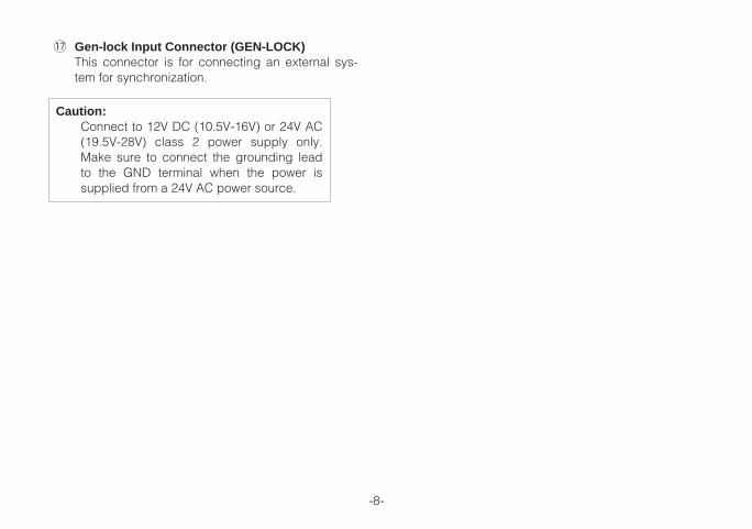
Caution:Connect to 12V DC (10.5V-16V) or 24V AC(19.5V-28V) class 2 power supply only.Make sure to connect the grounding leadto the GND terminal when the power issupplied from a 24V AC power source.
!7 Gen-lock Input Connector (GEN-LOCK) This connector is for connecting an external sys-tem for synchronization.
-9-
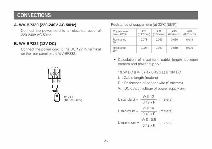
CONNECTIONS
A. WV-BP330 (220-240V AC 50Hz)Connect the power cord to an electrical outlet of220-240V AC 50Hz.
B. WV-BP332 (12V DC)Connect the power cord to the DC 12V IN terminalon the rear panel of the WV-BP332.
12 V DC(10.5 V - 16 V)
Copper wire #24 #22 #20 #18size (AWG) (0.22mm2) (0.33mm2) (0.52mm2) (0.83mm2)
Resistance 0.078 0.050 0.030 0.018Ω/m
Resistance 0.026 0.017 0.010 0.006Ω/ft
Resistance of copper wire [at 20°C (68°F)]
• Calculation of maximum cable length betweencamera and power supply :
10.5V DC ≤ VA − (R x 0.42 x L) ≤ 16V DC
L : Cable length (meters)
R : Resistance of copper wire (Ω/meters)
VA : DC output voltage of power supply unit
VA − 12L standard = (meters)
0.42 x R
VA − 16L minimum = (meters)
0.42 x R
VA − 10.5L maximum = (meters)
0.42 x R
@ !
-10-
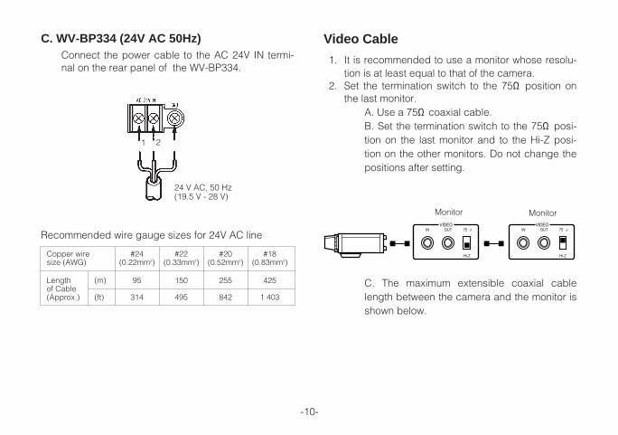
C. The maximum extensible coaxial cablelength between the camera and the monitor isshown below.
Video Cable
1. It is recommended to use a monitor whose resolu-tion is at least equal to that of the camera.
2. Set the termination switch to the 75Ω position onthe last monitor.
A. Use a 75Ω coaxial cable.B. Set the termination switch to the 75Ω posi-tion on the last monitor and to the Hi-Z posi-tion on the other monitors. Do not change thepositions after setting.
OUTIN 75 
Hi-Z
VIDEOOUTIN 75 
Hi-Z
VIDEO
Monitor Monitor
24 V AC, 50 Hz(19.5 V - 28 V)
1 2
C. WV-BP334 (24V AC 50Hz)Connect the power cable to the AC 24V IN termi-nal on the rear panel of the WV-BP334.
Copper wire #24 #22 #20 #18size (AWG) (0.22mm2) (0.33mm2) (0.52mm2) (0.83mm2)
Length (m) 95 150 255 425of Cable(Approx.) (ft) 314 495 842 1 403
Recommended wire gauge sizes for 24V AC line
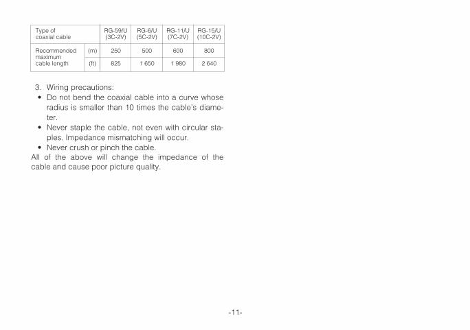
3. Wiring precautions:• Do not bend the coaxial cable into a curve whose
radius is smaller than 10 times the cable’s diame-ter.
• Never staple the cable, not even with circular sta-ples. Impedance mismatching will occur.
• Never crush or pinch the cable.All of the above will change the impedance of thecable and cause poor picture quality.
-11-
Type of RG-59/U RG-6/U RG-11/U RG-15/Ucoaxial cable (3C-2V) (5C-2V) (7C-2V) (10C-2V)
Recommended (m) 250 500 600 800maximumcable length (ft) 825 1 650 1 980 2 640
-12-
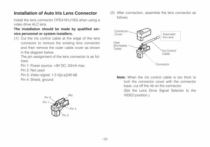
Installation of Auto Iris Lens ConnectorInstall the lens connector (YFE4191J100) when using avideo drive ALC lens.The installation should be made by qualified ser-vice personnel or system installers.(1) Cut the iris control cable at the edge of the lens
connector to remove the existing lens connectorand then remove the outer cable cover as shownin the diagram below.The pin assignment of the lens connector is as fol-lows:Pin 1: Power source; +9V DC, 50mA max.Pin 2: Not usedPin 3: Video signal; 1.3 V[p-p]/40 kΩPin 4: Shield, ground
Pin 3
Pin 4
Pin 2
Rib
Pin 1
Note: When the iris control cable is too thick tolock the connector cover with the connectorbase, cut off the rib on the connector.(Set the Lens Drive Signal Selector to theVIDEO position.)
(2) After connection, assemble the lens connector asfollows.
AutomaticIris Lens
Iris ControlCable
Connector
HeatShrinkableTubes
ConnectorCover
-13-
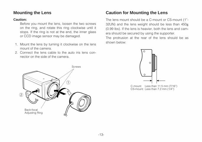
Caution for Mounting the Lens
The lens mount should be a C-mount or CS-mount (1”-32UN) and the lens weight should be less than 450g(0.99 lbs). If the lens is heavier, both the lens and cam-era should be secured by using the supporter.The protrusion at the rear of the lens should be asshown below:
C-mount: Less than 11.5 mm (7/16”)CS-mount: Less than 7.2 mm (1/4”)
1
2
Screws
Back-focalAdjusting Ring
Mounting the Lens
Caution:Before you mount the lens, loosen the two screwson the ring, and rotate this ring clockwise until itstops. If the ring is not at the end, the inner glassor CCD image sensor may be damaged.
1. Mount the lens by turning it clockwise on the lensmount of the camera.
2. Connect the lens cable to the auto iris lens con-nector on the side of the camera.
-14-
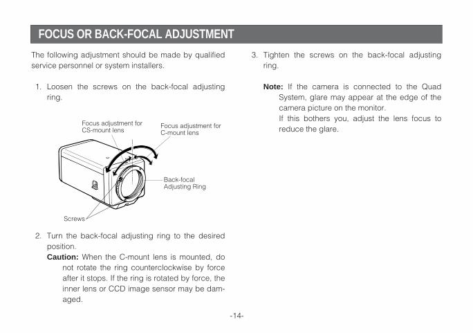
The following adjustment should be made by qualifiedservice personnel or system installers.
1. Loosen the screws on the back-focal adjustingring.
2. Turn the back-focal adjusting ring to the desiredposition.Caution: When the C-mount lens is mounted, do
not rotate the ring counterclockwise by forceafter it stops. If the ring is rotated by force, theinner lens or CCD image sensor may be dam-aged.
3. Tighten the screws on the back-focal adjustingring.
Note: If the camera is connected to the QuadSystem, glare may appear at the edge of thecamera picture on the monitor.If this bothers you, adjust the lens focus toreduce the glare.Focus adjustment for
C-mount lensFocus adjustment forCS-mount lens
Screws
Back-focalAdjusting Ring
FOCUS OR BACK-FOCAL ADJUSTMENT
-15-
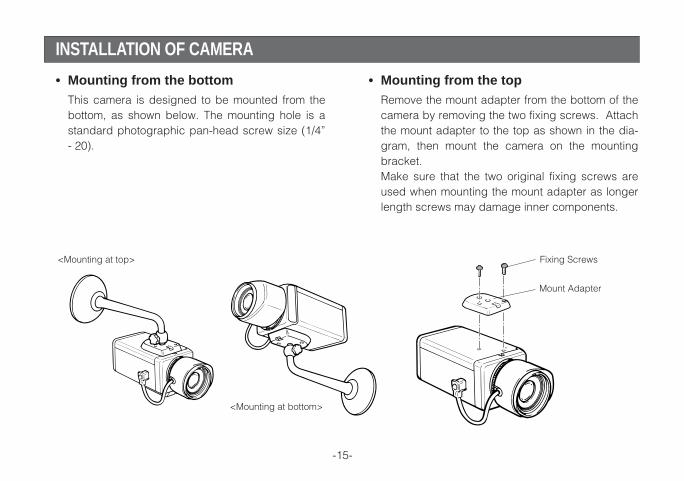
• Mounting from the bottomThis camera is designed to be mounted from thebottom, as shown below. The mounting hole is astandard photographic pan-head screw size (1/4”- 20).
• Mounting from the topRemove the mount adapter from the bottom of thecamera by removing the two fixing screws. Attachthe mount adapter to the top as shown in the dia-gram, then mount the camera on the mountingbracket.Make sure that the two original fixing screws areused when mounting the mount adapter as longerlength screws may damage inner components.
Fixing Screws
Mount Adapter
<Mounting at top>
<Mounting at bottom>
INSTALLATION OF CAMERA
-16-
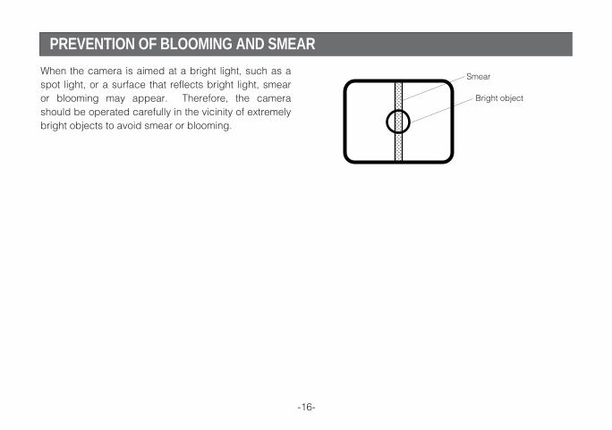
When the camera is aimed at a bright light, such as aspot light, or a surface that reflects bright light, smearor blooming may appear. Therefore, the camerashould be operated carefully in the vicinity of extremelybright objects to avoid smear or blooming.
Bright object
Smear
PREVENTION OF BLOOMING AND SMEAR
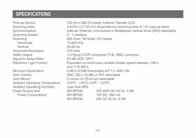
Pick-up Device: 752 (H) x 582 (V) pixels, Interline Transfer CCDScanning Area: 4.9 (H) x 3.7 (V) mm (Equivalent to scanning area of 1/3” pick-up tube)Synchronization: Internal, External, Line-locked or Multiplexed vertical drive (VD2) selectable Scanning System: 2 : 1 interlaceScanning: 625 lines / 50 fields / 25 frames
Horizontal: 15.625 kHzVertical: 50.00 Hz
Horizontal Resolution: 570 linesVideo Output: 1.0 V[p-p] CCIR composite 75 Ω / BNC connectorSignal-to-Noise Ratio: 50 dB (AGC OFF)Electronic Light Control: Equivalent to continuous variable shutter speed between 1/50 s
and 1/10 000 sMinimum Illumination: 0.08 lx (0.008 footcandle) at F1.4, AGC ONGain Control: AGC ON (+18 dB) or OFF selectableLens Mount: C-mount or CS-mount selectableAmbient Operating Temperature: −10°C - +50°C (14°F - 122°F)Ambient Operating Humidity: Less than 90%Power Source and WV-BP330: 220-240V AC 50 Hz, 4.5W
Power Consumption: WV-BP332: 12V DC, 250 mAWV-BP334: 24V AC 50 Hz, 3.5W
-17-
SPECIFICATIONS
Dimensions (without lens): 67 (W) x 55 (H) x 123 (D) mm[2-5/8” (W) x 2-3/16” (H) x 4-13/16” (D)]
Weights (without lens): WV-BP330: 0.635kg (1.40lbs)WV-BP332: 0.445kg (0.98lbs)WV-BP334: 0.470kg (1.04lbs)
Weights and dimensions indicated are approximate.Specifications are subject to change without notice.
-18-
STANDARD ACCESSORIES
Body Cap .....................................................................................1 pc.ALC Lens Connector (YFE4191J100) ..........................................1 pc.

Matsushita Electric Industrial Co., Ltd.Osaka, Japan
http://www.panasonic.co.jp/global/
N0103-5043 YWV8QA4917FN Printed in JapanN 30 Gedruckt in Japan
Imprimé au Japon2003 © Matsushita Electric Industrial Co., Ltd. All rights reserved. Impreso en Japón