Embed Size (px)
Citation preview

DIESEL
GENERATOR
OPEN FRAME:
K D E 8 0 0 0 E / E A K D E 12 0 0 0 E / E A K D E 8 0 0 0 E 3 / E A 3 K D E 12 0 0 0 E 3 / E A 3
K D E 8 0 0 0 T / TA K D E 12 0 0 0 T / TA K D E 8 0 0 0 T 3 / TA 3 K D E 12 0 0 0 T 3 / TA 3
SINGLE PHASE:
THREE PHASES:
SINGLE PHASE:
THREE PHASES:
SILENT:
WUXI KIPOR POWER CO., LTD.
R

PREFACE
Thank you for purchasing Kipor diesel generators.
This operation manual will tell you how to operate and service your KIPOR
generator set correctly. Please read this manual before using the generator set
to ensure the proper operation.Follow the instructions to keep your generator set
in the best working condition and extend the life of it .If you have any commends
or problem, please contact with our sales company or the authorized agent.
This manual deals with the general items of the KIPOR diesel generation set.
However, the manual may vary with the development of the products in the future.
Please give special attentions to warnings and cautions.
Indicates that the severe personal injury even death will
result if the instructions are not followed.
Indicates that the serious personal injury or equipment
damage will result if the instructions are not followed.
KIPOR diesel generator set will meet your requirement if you operate it according
to the manual instruction. Otherwise serious personal injury and equipment
damage will result.
So, KIPOR reconfirms that you must to read and understand this manual before
operating the generator set.
WARNING
CAUTION
24
23
22
21
20
19
18
17
16
15
14
13
12
11 10 9 8 7 6 5 4 3 2 1
SA
TC
GB
AV
R (
Dig
ital)
L1
SB
W3
W2
W1
BX
20
11C
BX
20
11C
FU
2F
U3
FU
1F
U4
YV
KM
1K
M2
K1
,K2
,K3
QF
1 1 1 1 1 1 1 1 2 1 2 3 1 1 1 1 B
eiYu
ele
ctric
app
lianc
e
R
em
ark
Co
de
na
me
Na
me
Q
ua
ntit
yM
ate
ria
l
Ign
itio
n s
witc
h
Tra
nsf
orm
er
Ch
arg
ing
ad
just
or
Ba
tte
ry
Au
tom
atic
vo
ltag
e a
dju
sto
r
Cu
rre
nt tr
an
sfo
rme
r
Em
erg
en
cy s
top
bu
tto
n
Fly
wh
ee
l ge
ne
rato
r w
ind
ing
Exc
itin
g w
ind
ing
Ge
ne
ratin
g/S
am
plin
g w
ind
ing
Fu
se li
nk
Fu
se li
nk
Fo
ur
line
fu
se b
ox
Fu
se (
ext
en
d 6
X3
01
0A
Th
rottle
ele
ctric
ma
gn
et
AC
co
nta
cto
r
Re
lay
AT
S m
od
ule
Dig
ital d
isp
lay
Dig
ital m
od
ule
Bre
ake
r
JK4
27
22
0V
/15
V 4
0A
35
Ah
6-Q
W-3
6 1
2V
36
Ah
31
0A
50
/5m
A
LA
Y3
7-1
1Z
S
10
A
20
A
BX
20
41
C
BX
20
1C
A2
6-4
0-0
0
HF
V4
12
V 2
0A
PLY
-MB
-AT
S-S
1
PLY
-MB
-D
PLY
-MB
3-A
TS
-C
D5
0/1
62
0 2
5A
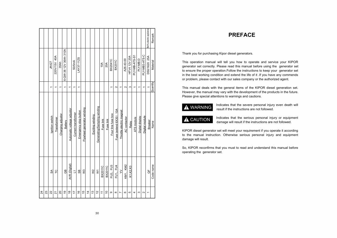
OFF
ON
START
Three phasesKDE8000EA3/TA3KDE12000EA3/TA3
ON/OFF Table for electric starting key
Red20#
Yellow green20#
KM1Brown white20# TC
DC charging output
~220V ~15V Blue white20# AC charging input
Red white20#
Black white20#
Black20#
Red20#
Yellow10#
Green10#
Red10#
Black10#
U
V
W
N
KM2
Yellow10#
Green10#
Red10#
Black10#
Yellow10#
Green10#
Red10#
Black10#
Yellow10#
Green10#
Red10#
Black10#
Yellow10#
Green10#
Red10#
Black10#
Yellow20#
Green20#Red20#
Black20#Red black20#
Brown black20#
Yellow black20#
U
V
W
N
E
ATS
con
trollin
g m
od
ule
Brown Blue20# KM2Orange blue20#
KM1
Citizen AC input
Generator AC signal input
Generator supplying output Purple gray20#
Yellow blue20# KM1Pink blue20#
KM2
Generator supplying output Purple black20#
Co
ntro
lling
sig
na
l
Citizen input
W2 Red18#F+
F-50HZ60H
6 37 4
Green18#
Yellow18#
L1
L1
L1
Blue18#
Red16#
K2
Brown16#
Blue20#
YV
A0
K1
W3K2
FU3
Blue20#
Yellow16#
Green16#
Ad
justo
r
Ba
ttery
Red18#
Red18
Red14# Green14#K3
Fu2
Fu1
Starting electric magnet
Starting motor
Pink 20#K3
Gray18# Starting signal output
White18#
Orange18#
Operation signal output
Voltage sample
SBPurple20#
Cu
rren
t sam
ple
SA
+12V
ST
ON
+12V
Dig
ital p
an
el d
ispla
y
OVAC voltage
sample for flywheelLow oil pressure switch
Digital panel display
Starting signal input
Yellow green18#
Purple orange18#
ATS options
KM1
Jerk signal input
24
23
22
21
20
19
18
17
16
15
14
13
12
11 10 9 8 7 6 5 4 3 2 1
X1
X
2
SA
TC
GB
AV
R (
Dig
ital)
L1
SB
W4
W3
W2
W1
BX
20
11C
BX
20
11C
FU
2F
U3
FU
1F
U4
YV
KM
1K
M2
K1
,K2
,K3
QF
2 1 1 1 1 1 1 1 1 2 1 2 3 1 1 1 1 B
eiYu
ele
ctric
app
lianc
e
R
em
ark
Co
de
na
me
Na
me
Q
ua
ntit
yM
ate
ria
l
Re
cep
tacl
e
Ign
itio
n s
witc
h
Tra
nsf
orm
er
Ch
arg
ing
ad
just
or
Ba
tte
ry
Au
tom
atic
vo
ltag
e a
dju
sto
r
Cu
rre
nt tr
an
sfo
rme
r
Em
erg
en
cy s
top
bu
tto
n
Fly
wh
ee
l ge
ne
rato
r w
ind
ing
Se
con
da
ry w
ind
ing
Exc
itin
g w
ind
ing
Ge
ne
ratin
g/S
am
plin
g w
ind
ing
Fu
se li
nk
Fu
se li
nk
Fo
ur
line
fu
se b
ox
Fu
se (
ext
en
d 6
X3
01
0A
Th
rottle
ele
ctric
ma
gn
et
AC
co
nta
cto
r
Re
lay
AT
S m
od
ule
Dig
ital d
isp
lay
Dig
ital m
od
ule
Bre
ake
r
Ho
nd
a o
r E
uro
pe
an
sty
le
JK4
27
22
0V
/15
V 4
0A
35
Ah
6-Q
W-3
6 1
2V
36
Ah
31
0A
50
/5m
A
LA
Y3
7-1
1Z
S
10
A
20
A
BX
20
41
C
BX
20
1C
A2
6-4
0-0
0
HF
V4
12
V 2
0A
PLY
-MB
-AT
S-S
2
PLY
-MB
-D
PLY
-MB
-AT
S-C
D5
0/1
62
0 2
5A
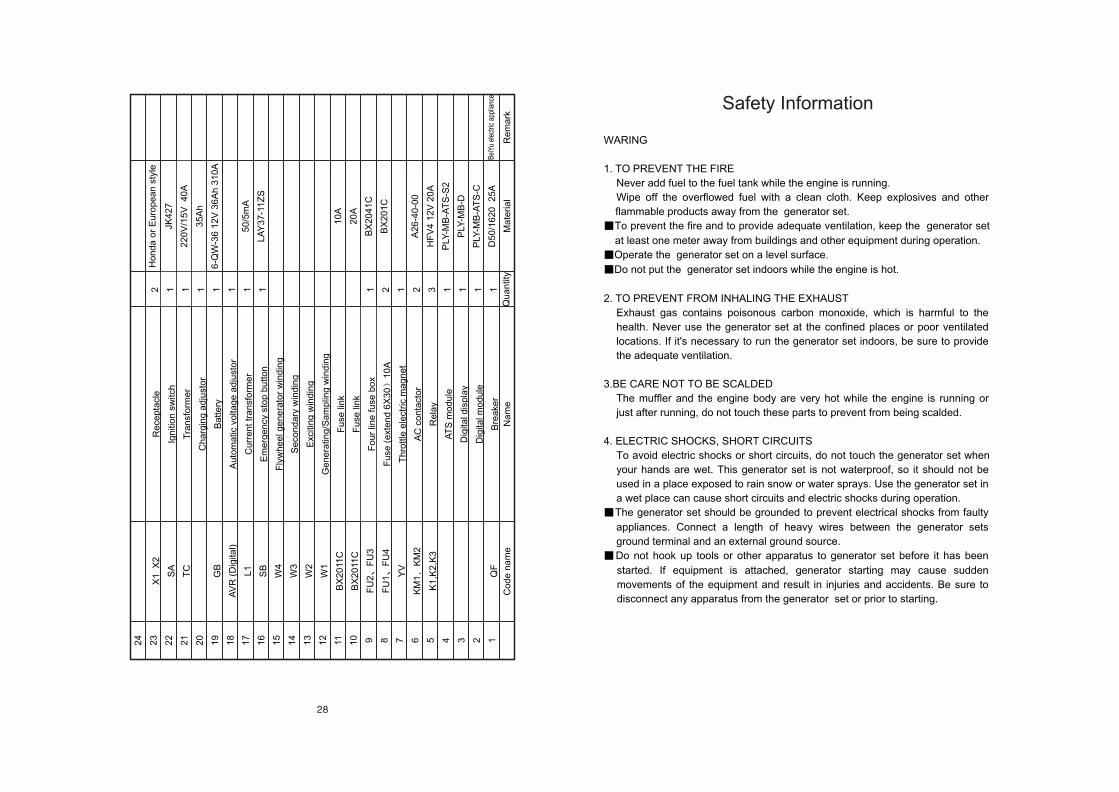
WARING
1. TO PREVENT THE FIRE
Never add fuel to the fuel tank while the engine is running.
Wipe off the overflowed fuel with a clean cloth. Keep explosives and other
flammable products away from the generator set.
To prevent the fire and to provide adequate ventilation, keep the generator set
at least one meter away from buildings and other equipment during operation.
Operate the generator set on a level surface.
Do not put the generator set indoors while the engine is hot.
2. TO PREVENT FROM INHALING THE EXHAUST
Exhaust gas contains poisonous carbon monoxide, which is harmful to the
health. Never use the generator set at the confined places or poor ventilated
locations. If it's necessary to run the generator set indoors, be sure to provide
the adequate ventilation.
3.BE CARE NOT TO BE SCALDED
The muffler and the engine body are very hot while the engine is running or
just after running, do not touch these parts to prevent from being scalded.
4. ELECTRIC SHOCKS, SHORT CIRCUITS
To avoid electric shocks or short circuits, do not touch the generator set when
your hands are wet. This generator set is not waterproof, so it should not be
used in a place exposed to rain snow or water sprays. Use the generator set in
a wet place can cause short circuits and electric shocks during operation.
The generator set should be grounded to prevent electrical shocks from faulty
appliances. Connect a length of heavy wires between the generator sets
ground terminal and an external ground source.
Do not hook up tools or other apparatus to generator set before it has been
started. If equipment is attached, generator starting may cause sudden
movements of the equipment and result in injuries and accidents. Be sure to
disconnect any apparatus from the generator set or prior to starting.
Safety Information
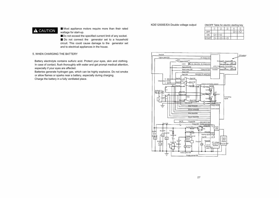
Most appliance motors require more than their rated
wattage for start-up.
Do not exceed the specified current limit of any socket.
Do not connect the generator set to a household
circuit. This could cause damage to the generator set
and to electrical appliances in the house.
5. WHEN CHARGING THE BATTERY
Battery electrolyte contains sulfuric acid. Protect your eyes, skin and clothing.
In case of contact, flush thoroughly with water and get prompt medical attention,
especially if your eyes are affected.
Batteries generate hydrogen gas, which can be highly explosive. Do not smoke
or allow flames or sparks near a battery, especially during charging.
Charge the battery in a fully ventilated place.
CAUTION
OFF
ON
START
KDE12000E/EA Double voltage output ON/OFF Table for electric starting key
Red20#
20#Yellow green
KM1
~220V ~15V Blue white AC charging input
TC
DC charging output
Citizen AC input
ATS controlling
module
ATS options
Generator AC signal input
Orange white20#
Red white20#
Black white 20#
Black 20#
Red 20#
Brown blue20# Orange blue20#
Yellow blue20# Pink blue20#
KM2KM1
KM2KM1
Citizen supplying output
Generator supplying output
Purple gray20#
Purple black20#
Controlling signal
Red10#
Black10#
Red10#
Red10#
Black10#
Red10#
N
U
Red12#
X3
240V
X1120V
Blue12#
X2
120V
Black12#
Yellow green12#
Voltage sample
Current sample
Digital panel
display
Digital panel
controller
Starting signal outputAC voltage sample for flywheel
OV
Low oil pressure
switch
Brown20#
Starting signal output
Gray18# ST
K3
ON+12V
+12VWhite18#
SA
Blue white20#
Brown white20#
Blue black20#
Brown black20#
Purple20#
Green18# Operation signal outputOrange18#
White18#
Purple orange18#
Yellow green18#
M Starting motor
Starting electric magnet
Red18#
Red18#
Red14# Green14#
FU1
FU2
K3
Pink20#
Adjustor
Battery Green16#
W4
Yellow16#
FU3
K1
Blue20#
Blue20#
YV
K2
A0
K1
Blue18#
Red16#
Brown16#
K2
Blue20#
SB
Red18#
Green18#W2
Yellow18#
Blue10#
Brown10#
Black10#
Yellow green12#
F+F-
6
73
4
50H60
W1
L1
W1
Citizen input~240V
KM2
Black10#
Jerk signal input
Output connection column
KM1
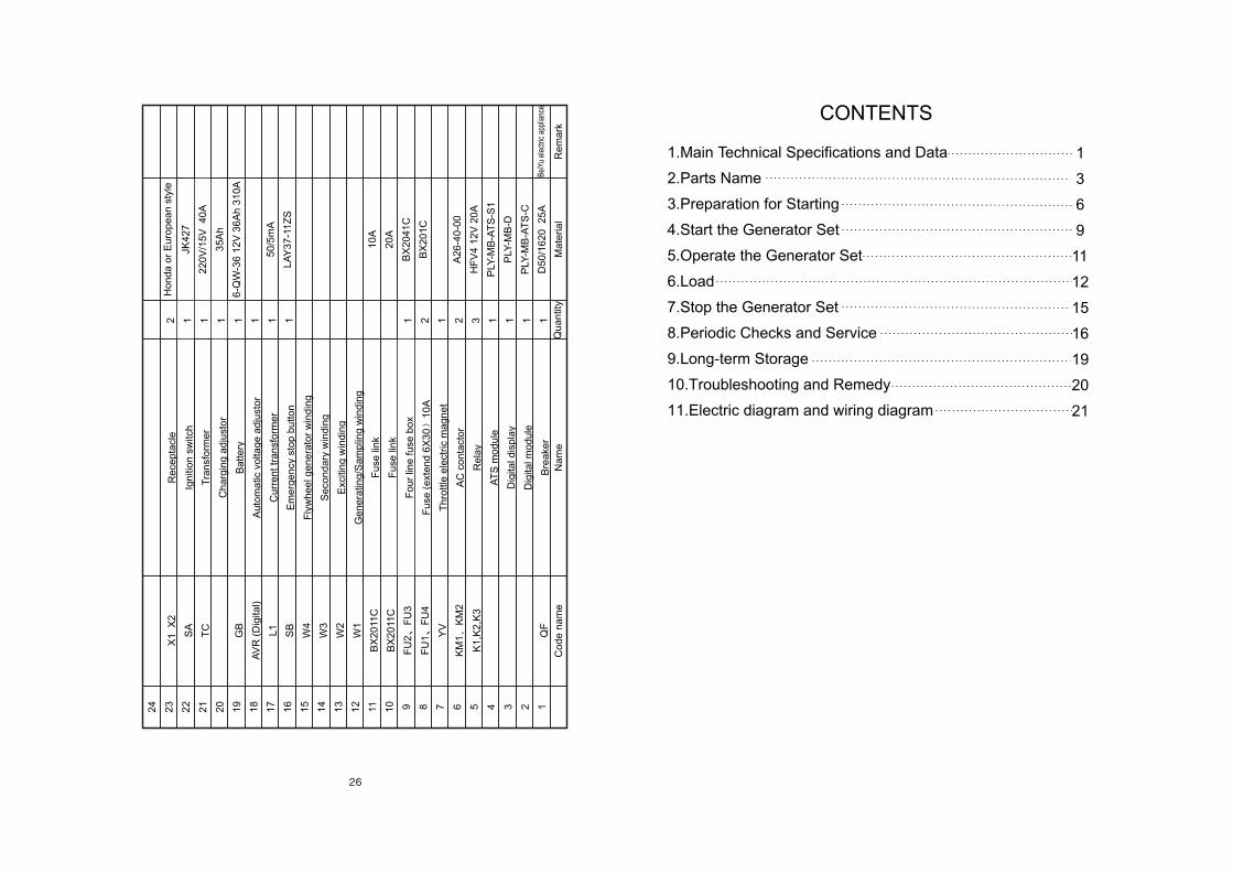
1.Main Technical Specifications and Data
2.Parts Name
3.Preparation for Starting
4.Start the Generator Set
5.Operate the Generator Set
6.Load
7.Stop the Generator Set
8.Periodic Checks and Service
9.Long-term Storage
10.Troubleshooting and Remedy
11.Electric diagram and wiring diagram
CONTENTS
1
3
6
9
11
12
15
16
19
20
21
24
23
22
21
20
19
18
17
16
15
14
13
12
11 10 9 8 7 6 5 4 3 2 1
X1
X
2
SA
TC
GB
AV
R (
Dig
ital)
L1
SB
W4
W3
W2
W1
BX
20
11C
BX
20
11C
FU
2F
U3
FU
1F
U4
YV
KM
1K
M2
K1
,K2
,K3
QF
2 1 1 1 1 1 1 1 1 2 1 2 3 1 1 1 1 B
eiYu
ele
ctric
app
lianc
e
R
em
ark
Co
de
na
me
Na
me
Q
ua
ntit
yM
ate
ria
l
Re
cep
tacl
e
Ign
itio
n s
witc
h
Tra
nsf
orm
er
Ch
arg
ing
ad
just
or
Ba
tte
ry
Au
tom
atic
vo
ltag
e a
dju
sto
r
Cu
rre
nt tr
an
sfo
rme
r
Em
erg
en
cy s
top
bu
tto
n
Fly
wh
ee
l ge
ne
rato
r w
ind
ing
Se
con
da
ry w
ind
ing
Exc
itin
g w
ind
ing
Ge
ne
ratin
g/S
am
plin
g w
ind
ing
Fu
se li
nk
Fu
se li
nk
Fo
ur
line
fu
se b
ox
Fu
se (
ext
en
d 6
X3
01
0A
Th
rottle
ele
ctric
ma
gn
et
AC
co
nta
cto
r
Re
lay
AT
S m
od
ule
Dig
ital d
isp
lay
Dig
ital m
od
ule
Bre
ake
r
Ho
nd
a o
r E
uro
pe
an
sty
le
JK4
27
22
0V
/15
V 4
0A
35
Ah
6-Q
W-3
6 1
2V
36
Ah
31
0A
50
/5m
A
LA
Y3
7-1
1Z
S
10
A
20
A
BX
20
41
C
BX
20
1C
A2
6-4
0-0
0
HF
V4
12
V 2
0A
PLY
-MB
-AT
S-S
1
PLY
-MB
-D
PLY
-MB
-AT
S-C
D5
0/1
62
0 2
5A
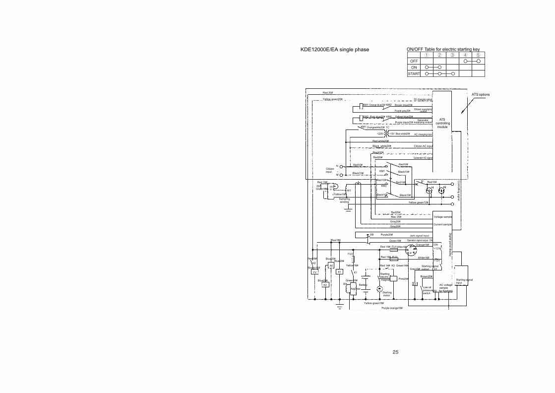
KDE12000E/EA single phase
OFF
ON
START
ON/OFF Table for electric starting key
ATS options
ATS controlling
module
DC charging output
Citizen supplying output
Generator supplying output
AC charging input
Citizen AC input
Generator AC signal
Red 20#
Black20#
Red20#
Red10# Red10#
Black10#
Black10# Black10#
Red10# KM2
KM1 Black10#
Voltage sample
Current sample
Yellow green12#
Red20#
Blac 20#
Red10#
NCitizen input ~ M
Gray20#
Gray20#
Yellow green20#
Sampling winding
KM1
KM2
KM1 Orange blue20# KM2
KM1Pink blue20#
Orangewhite20# TC
Red white20#
Black white20#
Purple black20#
Brown blue20#
Purple gray20#
~220V ~15V Blue white20#
Yellow blue20#
Red 18#
Green18#
Yellow18#
Operation signal output ON
Red 18# FU1
Red 18# FU2
White18# Orange18#
White18#
Red 14# K3 Green14#
Starting electric magnet
Starting motor
Starting signal input
Gray18#Starting signal output
Pink20# Brown20#
Low oil pressure switch
AC voltage sample 0V for flywheel
Yellow green18#
Purple orange18#
Blue20#
Blue20#
Blue20#
Brown16#Yellow16#
Green16#
Red16#
Adjustor
Battery
W2
W1
F+ 50HzF- 60 36 47
K3
K1
K2
A0
YV
K2
Blue18#
FU3
K1
W4
SB
Red10#
Co
ntro
lling
sign
al
Dig
ital p
an
el d
isp
lay
Purple20#
Green18#
+12V
ST
ON
+12V
Jerk signal input
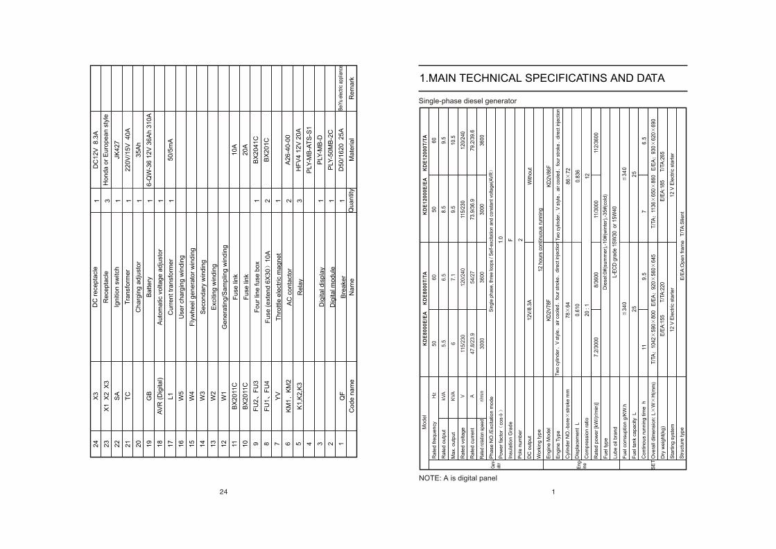
Single-phase diesel generator
NOTE: A is digital panel
1.MAIN TECHNICAL SPECIFICATINS AND DATA
KD
E8
00
0E
/EA
K
DE
80
00
T/T
A
12
V/8
.3A
KD
2V
78
F
78
64
0.6
10
20
: 1
L-E
CD
gra
de
15
W3
0 o
r 1
5W
40
Genr
-at
or
Mo
de
l
34
0
25
50
8.5
9.5
115
/23
0
73
.9/3
6.9
30
00
60
9.5
10.5
12
0/2
40
79
.2/3
9.6
36
00
Sin
gle
ph
ase
, th
ree
loo
ps
/ S
elf-
exc
itatio
n a
nd
co
nst
an
t vo
ltag
e(A
VR
1.0 F 2
12
ho
urs
co
ntin
uo
us
run
nin
g
With
ou
t
KD
2V
86
F
86
72
0.8
36
12
7.2
/30
00
8/3
60
011
/30
00
112
/360
0
34
0
25
119
.57
6.5
T/T
A1
04
25
90
80
0 E
/EA
92
056
06
45
T/T
A11
36
65
08
60 E
/EA
93
06
20
69
0
E/E
A:1
55
T
/TA
:22
0E
/EA
:18
5 T
/TA
:265
KD
E1
20
00
E/E
A K
DE
12
00
0T
/TA
Hz
kVA
KV
A
V A
r/m
in
Ra
ted
fre
qu
en
cy
Ra
ted
ou
tpu
t
Ma
x. o
utp
ut
Ra
ted
vo
ltag
e
Ra
ted
cu
rre
nt
Ph
ase
NO
./E
xcita
tion
mo
de
Po
we
r fa
cto
rco
s
Insu
latio
n G
rad
e
Po
le n
um
be
r
DC
ou
tpu
t
Wo
rkin
g typ
e
En
gin
e M
od
el
En
gin
e T
ype
Cyl
ind
er
NO
.-b
ore
stro
ke m
m
Dis
pla
cem
en
t L
Co
mp
ress
ion
ra
tio
Ra
ted
po
we
r [k
W/(
r/m
in)]
Fu
el ty
pe
Lu
be
oil
bra
nd
Fu
el co
msu
ptio
n g
/KW
.h
Fu
el ta
nk
cap
aci
ty L
Co
ntin
ou
s ru
nn
ing
tim
e h
Ove
rall
dim
en
sio
n: L
WH
(mm
)
Dry
we
igh
t(kg
)
Sta
rtin
g s
yste
m
Str
uct
ure
typ
e
Rat
ed r
otat
ion
spee
d
Eng
-in
e
SE
T
Tw
o c
ylin
de
rV
sty
lea
ir c
oo
led
fou
r st
roke
dire
ct in
ject
ion
Tw
o c
ylin
de
rV
sty
lea
ir c
oo
led
fou
r st
roke
dire
ct in
ject
ion
E/E
A:O
pe
n fra
me
T
/TA
:Slie
nt
Die
sel:0
#(s
um
me
r),-
10
#(w
inte
r),-
35
#(c
old
)
12
V E
lect
ric
sta
rte
r1
2 V
Ele
ctric
sta
rte
r
24
23
22
21
20
19
18
17
16
15
14
13
12
11 10 9 8 7 6 5 4 3 2 1
X3
X1
X
2 X
3
SA
TC
GB
AV
R (
Dig
ital)
L1
W5
W4
W3
W2
W1
BX
20
11C
BX
20
11C
FU
2F
U3
FU
1F
U4
YV
KM
1K
M2
K1
,K2
,K3
QF
1 3 1 1 1 1 1 1 1 2 1 2 3 1 1 1
DC
12
V 8
.3A
JK4
27
22
0V
/15
V 4
0A
35
Ah
6-Q
W-3
6 1
2V
36
Ah
31
0A
50
/5m
A
10
A
20
A
BX
20
41
C
BX
20
1C
A2
6-4
0-0
0
HF
V4
12
V 2
0A
PLY
-MB
-AT
S-S
1
PLY
-MB
-D
PLY
-50
MB
-2C
D5
0/1
62
0 2
5A
Bei
Yu e
lect
ric a
pplia
nce
R
em
ark
Co
de
na
me
Na
me
Q
ua
ntit
yM
ate
ria
l
DC
re
cep
tacl
e
Re
cep
tacl
e
Ign
itio
n s
witc
h
Tra
nsf
orm
er
Ch
arg
ing
ad
just
or
Ba
tte
ry
Au
tom
atic
vo
ltag
e a
dju
sto
r
Cu
rre
nt tr
an
sfo
rme
r
Use
r ch
arg
ing
win
din
g
Fly
wh
ee
l ge
ne
rato
r w
ind
ing
Se
con
da
ry w
ind
ing
Exc
itin
g w
ind
ing
Ge
ne
ratin
g/S
am
plin
g w
ind
ing
Fu
se li
nk
Fu
se li
nk
Fo
ur
line
fu
se b
ox
Fu
se (
ext
en
d 6
X3
01
0A
Th
rottle
ele
ctric
ma
gn
et
AC
co
nta
cto
r
Re
lay
Dig
ital d
isp
lay
Dig
ital m
od
ule
Bre
ake
r
Ho
nd
a o
r E
uro
pe
an
sty
le
50
5.5 6
115
/23
0
47
.8/2
3.9
30
00
60
6.5
7.1
12
0/2
40
54
/27
36
00
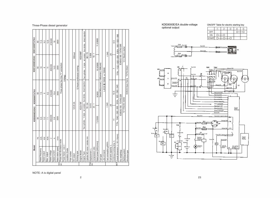
Three-Phase diesel generator
NOTE: A is digital panel
OFF
ON
START
ON/OFF Table for electric starting keyKDE8000E/EA double-voltage optional output
Black16#
Yellow16#Blue16#
Red16#
Blue16#
Yellow16#
Red18#
Blue18#
Green18#
Blue18#
Yellow18#
Yellow18#
Sampling winding
Red10#
Red10#
Brown10#
Black10#
Brown10#
Red10#
Blue10#
Black10#
Black10#
Red green20#
Red blue20#
Red white20#
Blue white20#
Brown white20#
Black white20#
Red black 20#
Blue black20#
Brown black20#
Black20#
Yellow green20#
Operation signal outputBlue18 #
Red18# White18#
Red18# White18# +20V
Orange18#
Red14# Green14#
Digital panel display
Digital panel controller
AC voltage sample for flywheel
Low oil pressure switch
Gray18#
Pink20# Brown20#
Starting signal output
Adjustor
Battery
Starting electric magnet
Starting motor
Blue20 #Red16#
Brown16#
Blue20 #
Blue20 #
Green16#
Yellow18#
1
KD
E8
00
0E
3/E
A3
K
DE
80
00
T3
/TA
3
L-E
CD
1
5W
30
o
r 1
5W
40
34
0
25
F 2
KD
2V
86
F
86
72
0.8
36
19
: 1
10
.3/3
00
011
.3/3
60
0
34
0
25
11
10
.57
6.5
T/T
A1
04
25
90
80
0 E
/EA
92
05
60
64
5
E3
/EA
3:1
55
T
3/T
A3
:22
0E
3/E
A3
:18
5 T
3/T
A3
:26
5
KD
E1
20
00
E3
/EA
3 K
DE
12
00
0T
3/T
A3
Hz
kVA
KW
KV
A
V A
r/m
in
Ra
ted
fre
qu
en
cy
Ra
ted
ou
tpu
t
Ma
x. o
utp
ut
Ra
ted
vo
lta
ge
Ra
ted
cu
rre
nt
Ph
ase
NO
./E
xcita
tion
mo
de
Po
we
r fa
cto
rco
s
Insu
latio
n G
rad
e
Po
le n
um
be
r
DC
ou
tpu
t
Wo
rkin
g typ
e
En
gin
e M
od
el
En
gin
e T
ype
Cyl
ind
er
NO
.-b
ore
stro
ke m
m
Dis
pla
cem
en
t L
Co
mp
ress
ion
ra
tio
Ra
ted
po
we
r [k
W/(
r/m
in)]
Fu
el t
ype
Lu
be
oil
bra
nd
Fu
el c
om
sup
tion
g/K
W.h
Fu
el t
an
k ca
pa
city
L
Co
ntin
ou
s ru
nn
ing
tim
e h
Ove
rall
dim
en
sio
n: L
WH
(mm
)
Dry
we
igh
t(kg
)
Sta
rtin
g s
yste
m
Str
uct
ure
typ
e
Rat
ed r
otat
ion
spee
dGe
nr-
ator
Eng
-in
e
SE
T
Mo
de
l
Tw
o c
ylin
de
rV
sty
lea
ir c
oo
led
fou
r st
roke
dire
ct in
ject
ion
Tw
o c
ylin
de
rV
sty
lea
ir c
oo
led
fou
r st
roke
dire
ct in
ject
ion
Die
sel:0
#(s
um
me
r),-
10
#(w
inte
r),-
35
#(c
old
)
E3
/EA
3:O
pe
n fra
me
T
3/T
A3
:Slie
nt
12
V E
lect
ric
sta
rte
r
With
ou
t
12
ho
urs
co
ntin
uo
us
run
nin
g
Th
ree
ph
ase
fo
ur
line
,"Y
" co
nn
ect
ion
0.8
(la
g)
12
V E
lect
ric
sta
rte
r
T/T
A11
22
62
08
30
E
/EA
93
06
20
69
0
12
V/8
.3A
KD
2V
78
F
78
64
0.6
10
20
: 1
7.2
/30
00
8/3
60
0
50
6.5
5.2
7.1
40
0/2
30
9.4
30
00
60
7.5 6 8.2
41
6/2
40
10
.4
36
00
60
11.5
9.2
12
.6
41
6/2
40
16
36
00
50
10 8 11
40
0/2
30
14
.5
30
00
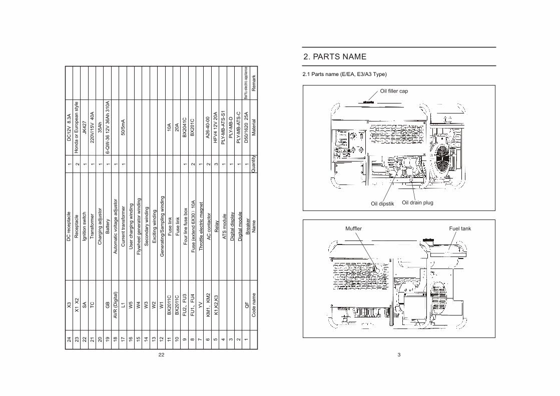
2. PARTS NAME
2.1 Parts name (E/EA, E3/A3 Type)
Oil dipstik Oil drain plug
Muffler Fuel tank
Oil filler cap
24
23
22
21
20
19
18
17
16
15
14
13
12
11 10 9 8 7 6 5 4 3 2 1
X3
X1
X
2
SA
TC
GB
AV
R (
Dig
ital)
L1
W5
W4
W3
W2
W1
BX
20
11C
BX
20
11C
FU
2F
U3
FU
1F
U4
YV
KM
1K
M2
K1
,K2
,K3
QF
1 2 1 1 1 1 1 1 1 2 1 2 3 1 1 1 1
DC
12
V 8
.3A
JK4
27
22
0V
/15
V 4
0A
35
Ah
6-Q
W-3
6 1
2V
36
Ah
31
0A
50
/5m
A
10
A
20
A
BX
20
41
C
BX
20
1C
A2
6-4
0-0
0
HF
V4
12
V 2
0A
PLY
-MB
-AT
S-S
1
PLY
-MB
-D
PLY
-MB
-AT
S-C
D5
0/1
62
0 2
5A
Bei
Yu e
lect
ric a
pplia
nce
R
em
ark
Co
de
na
me
Na
me
Q
ua
ntit
yM
ate
ria
l
DC
re
cep
tacl
e
Re
cep
tacl
e
Ign
itio
n s
witc
h
Tra
nsf
orm
er
Ch
arg
ing
ad
just
or
Ba
tte
ry
Au
tom
atic
vo
ltag
e a
dju
sto
r
Cu
rre
nt tr
an
sfo
rme
r
Use
r ch
arg
ing
win
din
g
Fly
wh
ee
l ge
ne
rato
r w
ind
ing
Se
con
da
ry w
ind
ing
Exc
itin
g w
ind
ing
Ge
ne
ratin
g/S
am
plin
g w
ind
ing
Fu
se li
nk
Fu
se li
nk
Fo
ur
line
fu
se b
ox
Fu
se (
ext
en
d 6
X3
01
0A
Th
rottle
ele
ctric
ma
gn
et
AC
co
nta
cto
r
Re
lay
AT
S m
od
ule
Dig
ital d
isp
lay
Dig
ital m
od
ule
Bre
ake
r
Ho
nd
a o
r E
uro
pe
an
sty
le
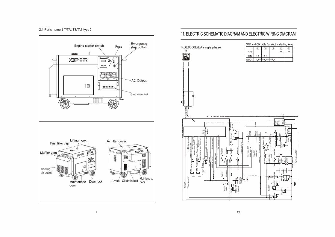
2.1 Parts name T/TA, T3/TA3 type
Engine starter switch Fuse
Fuel filler cap
Coolingair outlet
Emergencg stop button
AC Output
AT
S o
ptio
ns
AT
S c
on
tro
llin
g
mo
du
le
DC
ch
arg
ing
ou
tpu
t
Citiz
en
su
pp
lyin
g o
utp
ut
Gen
era
tor
supply
ing o
utp
ut
AC
ch
arg
ing
inp
ut
Citiz
en
AC
inp
ut
Ge
ne
rato
r A
C s
ign
al
Co
ntr
olli
ng
si
gn
al
Re
d 2
0#
Re
d b
lack
20
#
Re
d1
0#
Re
d1
0#
Re
d1
0#
Bla
ck1
0#
Bla
ck1
0#
B
lack
10
#
Re
d1
0#
K
M2
KM
1
Bla
ck1
0#
Vo
lta
ge
sa
mp
le
Cu
rre
nt
sa
mp
le
Ye
llow
gre
en
12
#
Re
d b
lack
20
#
Bla
ck r
ed20
#
Re
d1
0#
Citiz
en
in
pu
t
Gra
y20
#
Gra
y20
#
Ye
llow
gre
en
20
#
Sa
mp
ling
w
ind
ing
KM
1
KM
2
KM
1
Ora
nge
blue
20#
KM
2
KM
1P
ink
blu
e2
0#
Ora
ng
e w
hite
20
# T
C
Re
d w
hite
20
#
Ye
llow
wh
ite2
0#
Pu
rple
bla
ck2
0#
Bro
wn
blu
e2
0#
Pur
ple
gray
20#
Blu
e w
hite
20#
Ye
llow
blu
e2
0#
W2
Re
d 1
8#
Gre
en
18
#
W3
Blu
e1
8#
Ye
llow
18
#B
lue
18
#
Op
era
tion
sig
na
l ou
tpu
t O
NB
lue
18
#
Re
d 1
8#
F
U1
Re
d 1
8#
F
U2
Wh
ite1
8#
Ora
ng
e1
8#
Wh
ite
18
#
Re
d 1
4#
K
3 G
ree
n1
4#
Sta
rtin
g
ele
ctric
ma
gn
et
Sta
rtin
g m
oto
r
Dig
ital
pa
ne
l d
isp
lay
Sta
rtin
g s
ign
al
inp
ut
Gra
y1
8#
Sta
rtin
g s
ign
al
ou
tpu
t
Pin
k2
0#
Bro
wn
20
#
Lo
w o
il p
ress
ure
sw
itch
AC
vo
lta
ge
sa
mp
le
for
flyw
he
el
Ye
llow
gre
en
18
#
Pu
rple
ora
ng
e1
8#
Blu
e2
0#
Blu
e2
0#
Blu
e2
0#
Bro
wn
16
#Y
ello
w1
6#
Gre
en
16
#
Re
d1
6#
Ad
justo
r
Ba
tte
ry
11. ELECTRIC SCHEMATIC DIAGRAM AND ELECTRIC WIRING DIAGRAM
KDE8000E/EA single phaseOFF and ON table for electric starting key
OFF
ON
START
Ground terminal
MaintenacedoorDoor lock
Lifting hook
Muffler vent
Air filter cover
Brake Oil drain boltMaintenacedoor
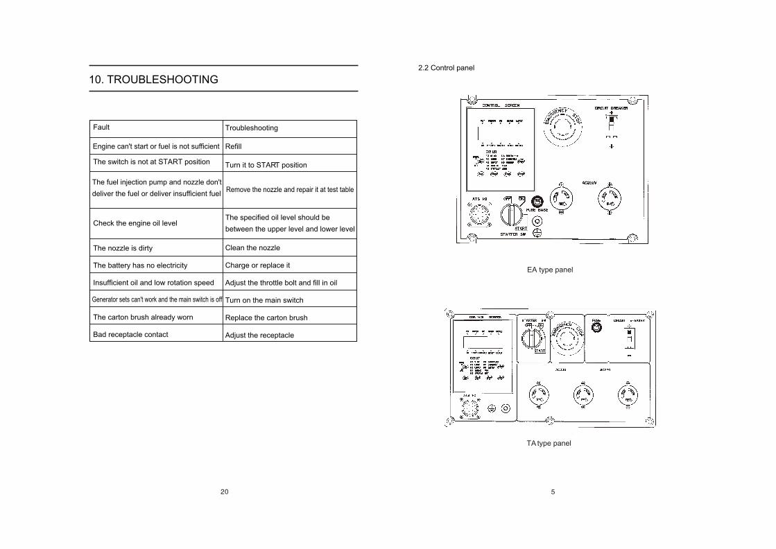
2.2 Control panel
EA type panel
TA type panel
10. TROUBLESHOOTING
Fault
The switch is not at START position
The nozzle is dirty
The battery has no electricity
Insufficient oil and low rotation speed
The carton brush already worn
Bad receptacle contact
The fuel injection pump and nozzle don't
deliver the fuel or deliver insufficient fuel
Generator sets can't work and the main switch is off
Engine can't start or fuel is not sufficient
Troubleshooting
Refill
Turn it to START position
The specified oil level should be
between the upper level and lower level
Remove the nozzle and repair it at test table
Check the engine oil level
Clean the nozzle
Charge or replace it
Adjust the throttle bolt and fill in oil
Turn on the main switch
Replace the carton brush
Adjust the receptacle
3. PREPARATION FOR STARTING
3.1 Selection and using of the fuel
Selection of fuel
Only use the light diesel, which is most suitable for the engine.
Keep dust and water out of the fuel
When filling the fuel tank from drums, make sure that no dust or water is mixed
in the fuel. Otherwise the serious fuel injection pump and nozzle problems will
result.
Do not overfill
Overfilling is very dangerous. Do not fill the tank beyond the top of the red plug
inside the fuel filter.
WARNING
WARNING
Refuel in a well-ventilated area with the engine stopped.
Do not smoke or allow flames or sparks in the area where the engine is ref-
ueled or where the fuel stored.
Do not overfill the tank, make sure the filler cap is securely closed after
refueling.
Be careful not to spill fuel when refueling. If any fuel is spilled, make sure
the area is dry before starting the engine
Always check the oil level with the generator set on a level surface before
staring and refill if necessary.
The engine may be damaged if operated with insufficient oil, it is also
dangerous to refill too engine oil as sudden increase in engine speed may be
caused by its combustion.
3.2 Check and refill the oil
CAUTION:
KIPOR KDE series generator set are equipped with low oil alarm system. This
system will stop the engine automatically when the oil level falls below the lower
level. This prevents accidents such as bearing seizures, etc.
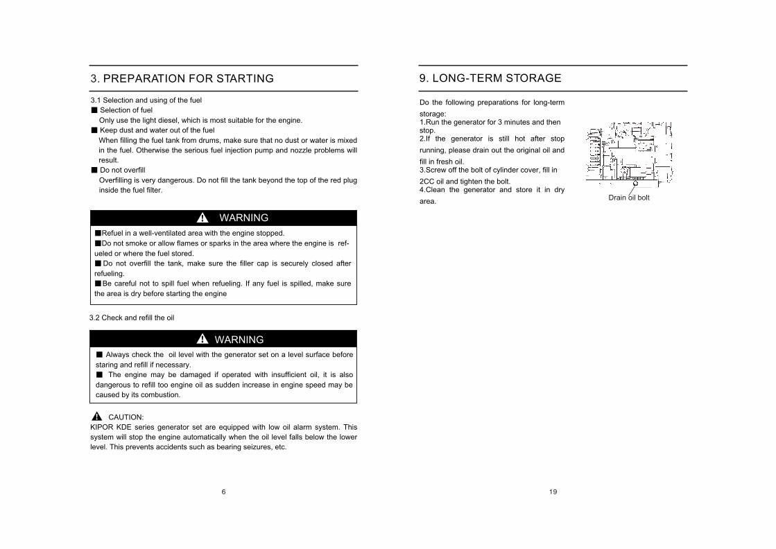
9. LONG-TERM STORAGE
Do the following preparations for long-term
storage:1.Run the generator for 3 minutes and then stop.2.If the generator is still hot after stop
running, please drain out the original oil and
fill in fresh oil.3.Screw off the bolt of cylinder cover, fill in
2CC oil and tighten the bolt.4.Clean the generator and store it in dry
area. Drain oil bolt

Select the most applicable oil
It is very important to select the applicable oil in order to keep up the
performance and life of the generator set. If inferior oil is used, or if your oil is
not replaced periodically, the risk of piston seizure, piston ring sticking and
accelerated wear of the cylinder liner, bearing and other moving components
will increase significantly. So the generator set life will be shortened. KIPOR
recommends CC/CD oil classified by API. Choose the applicable viscosity oil
according to the local ambient temperature.
3.3 Check the air cleaner
1.Screw off the wing nut, remove the air cleaner
cover and take out the element.
CAUTION:
Do not wash the element with detergent.
Replace the element when its output decrease
or a bad exhaust color is noticed.
Never run the generator set without the elem-
ent, otherwise the rapid engine wear will result.
2. Reattach the air clearer cover and screw on the
wing nut.
Air cleaner
Air cleaner cover
Element
WARNING
1. Drain out the fuel from the fuel tank.
2. Drain out the fuel from the fuel tank.
Screw off the small screw of the fuel cock and pull out the filter from the filler
port.
3. Wash the filter thoroughly with diesel fuel.
Loosen the fastening nut, bottom cover and delivery discs for cleaning the
deposit carbon.
8.5 Tighten cylinder head bolt
Tightening the cylinder head bolt requires a special tool. Do not try yourself.
Contact with KIPOR agent.
8.6 Check the injection nozzle and fuel injection pump
1. Adjust the clearance of the intake/exhaust valves.
2. Grind the intake/exhaust valves.
3. Replace the piston ring
Do not perform the injection nozzle test near an open fire or any other kind of
fire. The fuel spray may ignite. Do not expose bare skin to the fuel spray. The
fuel may penetrate the skin and cause injury to the body. Always keep your
body away from the nozzle.
8.7 Check and refill the battery electrolyte and charge the battery
The diesel uses a 12V battery. Battery electrolyte will be lost through continuous
charging and discharging.
Before starting, check for physical damage to the battery and also the electrolyte
levels, and refill the distilled water till to the upper lever if necessary. When actual
damage is discovered, replace the battery.
Check the battery electrolyte monthly.
WARNING
The battery electrolyte contains sulfuric acid. Protect your eyes, skin and
clothing. In case of contact, flush thoroughly with water and get prompt medical
attention, especially if your eyes are affected.The battery exhaust hydrogen gas, which can be highly explosive. Do not
smoke or allow flames or sparks near the battery, especially during charging.
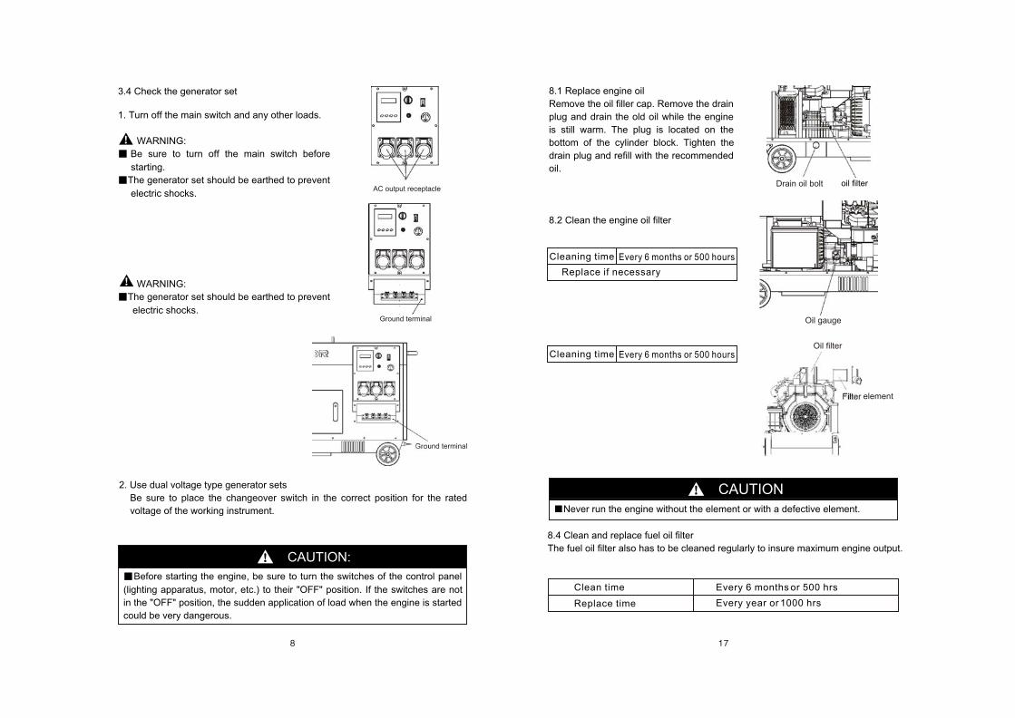
AC output receptacle
Ground terminal
Ground terminal
3.4 Check the generator set
1. Turn off the main switch and any other loads.
WARNING:
Be sure to turn off the main switch before
starting.
The generator set should be earthed to prevent
electric shocks.
WARNING:
The generator set should be earthed to prevent
electric shocks.
2. Use dual voltage type generator sets
Be sure to place the changeover switch in the correct position for the rated
voltage of the working instrument.
CAUTION:
Before starting the engine, be sure to turn the switches of the control panel
(lighting apparatus, motor, etc.) to their "OFF" position. If the switches are not
in the "OFF" position, the sudden application of load when the engine is started
could be very dangerous.
CAUTION
Drain oil bolt oil filter
Oil filter
Filter element
8.1 Replace engine oil
Remove the oil filler cap. Remove the drain
plug and drain the old oil while the engine
is still warm. The plug is located on the
bottom of the cylinder block. Tighten the
drain plug and refill with the recommended
oil.
8.2 Clean the engine oil filter
Cleaning time
Replace if necessary
Every 6 months or 500 hours
Cleaning time Every 6 months or 500 hours
8.4 Clean and replace fuel oil filter
The fuel oil filter also has to be cleaned regularly to insure maximum engine output.
Never run the engine without the element or with a defective element.
Clean time
Replace time
Every 6 months or 500 hrs
Every year or 1000 hrs
Oil gauge
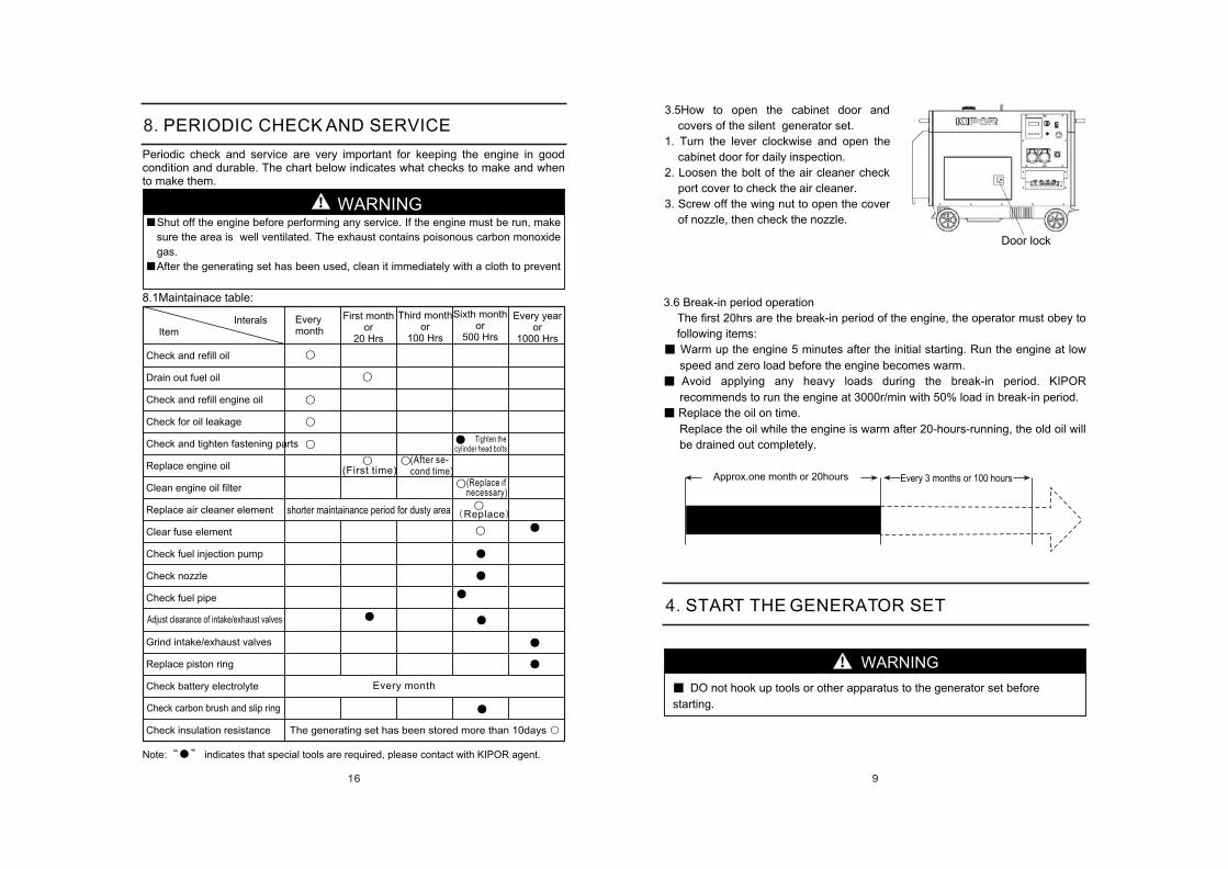
3.5How to open the cabinet door and
covers of the silent generator set.
1. Turn the lever clockwise and open the
cabinet door for daily inspection.
2. Loosen the bolt of the air cleaner check
port cover to check the air cleaner.
3. Screw off the wing nut to open the cover
of nozzle, then check the nozzle.
3.6 Break-in period operation
The first 20hrs are the break-in period of the engine, the operator must obey to
following items:
Warm up the engine 5 minutes after the initial starting. Run the engine at low
speed and zero load before the engine becomes warm.
Avoid applying any heavy loads during the break-in period. KIPOR
recommends to run the engine at 3000r/min with 50% load in break-in period.
Replace the oil on time.
Replace the oil while the engine is warm after 20-hours-running, the old oil will
be drained out completely.
Approx.one month or 20hours Every 3 months or 100 hours
DO not hook up tools or other apparatus to the generator set before
starting.
4. START THE GENERATOR SET
WARNING
8. PERIODIC CHECK AND SERVICE
shorter maintainance period for dusty area
The generating set has been stored more than 10days
8.1Maintainace table:
Shut off the engine before performing any service. If the engine must be run, make
sure the area is well ventilated. The exhaust contains poisonous carbon monoxide
gas.
After the generating set has been used, clean it immediately with a cloth to prevent
WARNING
Periodic check and service are very important for keeping the engine in good condition and durable. The chart below indicates what checks to make and when to make them.
Check and refill oil
Drain out fuel oil
Check and refill engine oil
Check for oil leakage
Check and tighten fastening parts
Replace engine oil
Clean engine oil filter
Replace air cleaner element
Clear fuse element
Check fuel injection pump
Check nozzle
Check fuel pipe
Grind intake/exhaust valves
Replace piston ring
Check battery electrolyte
Check insulation resistance
Every year or
1000 HrsItem
Interals Everymonth
First month or
20 Hrs
Third month or
100 Hrs
Sixth month or
500 Hrs
Adjust clearance of intake/exhaust valves
Check carbon brush and slip ring
Note: indicates that special tools are required, please contact with KIPOR agent.
Every month
(First time)(Replace if necessary)
Replace
(After se-cond time)
Tighten the cylinder head bolts
Door lock
CAUTION
Running the starter motor for long time, it may consume the power, even destr-
oy the battery.
Put the start switch at the "ON" position while the engine is running.
CAUTION
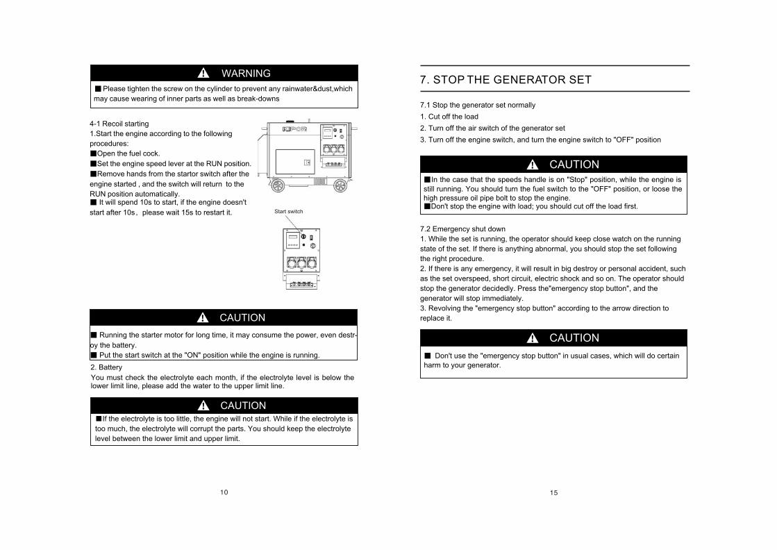
Start switch
WARNING
4-1 Recoil starting
1.Start the engine according to the following
procedures:
Open the fuel cock.
Set the engine speed lever at the RUN position.
Remove hands from the startor switch after the
engine started , and the switch will return to the
RUN position automatically. It will spend 10s to start, if the engine doesn't
start after 10s please wait 15s to restart it.
You must check the electrolyte each month, if the electrolyte level is below the lower limit line, please add the water to the upper limit line.
2. Battery
If the electrolyte is too little, the engine will not start. While if the electrolyte is
too much, the electrolyte will corrupt the parts. You should keep the electrolyte
level between the lower limit and upper limit.
Please tighten the screw on the cylinder to prevent any rainwater&dust,which
may cause wearing of inner parts as well as break-downs7.1 Stop the generator set normally
1. Cut off the load
2. Turn off the air switch of the generator set
3. Turn off the engine switch, and turn the engine switch to "OFF" position
CAUTION
CAUTION
Don't use the "emergency stop button" in usual cases, which will do certain
harm to your generator.
7. STOP THE GENERATOR SET
In the case that the speeds handle is on "Stop" position, while the engine is
still running. You should turn the fuel switch to the "OFF" position, or loose the high pressure oil pipe bolt to stop the engine.
Don't stop the engine with load; you should cut off the load first.
7.2 Emergency shut down
1. While the set is running, the operator should keep close watch on the running
state of the set. If there is anything abnormal, you should stop the set following
the right procedure.
2. If there is any emergency, it will result in big destroy or personal accident, such
as the set overspeed, short circuit, electric shock and so on. The operator should
stop the generator decidedly. Press the"emergency stop button", and the
generator will stop immediately.
3. Revolving the "emergency stop button" according to the arrow direction to
replace it.
5. OPERATE THE GENERATOR SET
5.1Operate the generaor set
1. Warm up the engine without load three minutes.
2. Concerning the generator set with Low Oil Alarm System, check that the Low
oil alarm Lamp is not lit.
CAUTION
For the generator set with Low Oil Alarm System, the Oil Alarm Lamp will
activated by low oil pressure or engine oil shortage, simultaneously, the
engine will stop. The engine will stop immediately if restarted without
refilling the engine oil. Check the oil level and refill.
Do not loosen or readjust either the engine speed limiting bolt or fuel
injection limiting bolt, the performance will be affected.
5.2 Checks during the running
1. Whether there is abnormal sound or vibration;
2. Whether the engine misfires or runs rough;
3. Check the color of the exhaust. (Is it black or too white?)
If you notice any of the above-mentioned phenomenon happened, stop the en-
gine and find out the fault cause or contact with KIPOR agent.
If the engine has been running, the muffler will be very hot. Be careful not to
touch the muffler.
Never refill the fuel tank while the engine is running.
CAUTION
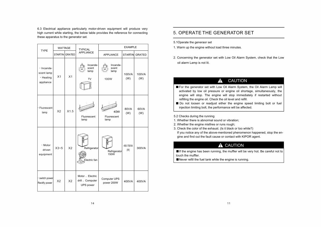
Fluorescent
lamp
Motor
driven
equipment
X1
X2
X3~5
X1
X1.5
X2
100VA
(W)
100VA
(W)
80VA
(W)
60VA
(W)
450-750VA
(W)300VA
40W
100W
switch power
Rectify powerX2X2
Computer UPS
power 200W 400VA400VA
6.3 Electrical appliance particularly motor-driven equipment will produce very
high current while starting, the below table provides the reference for connecting
these apparatus to the generator set.
APPLIANCE STARTIN GRATED
Refrigerator150W
TYPICALAPPLIANCE
TYPE WATTAGE EXAMPLE
STARTIN GRATED
Incande-
scent lamp
Heating
appliance
Incande-scent lamp
TV
Incande-scent lamp
Fluorescentlamp
Fluorescentlamp
Refrigerator
Electric fan
Motor Electric
drill Computer
UPS power
CAUTION
6. LOAD
NOTE
Do not start 2 or more machines simultaneously. Start them one by one.
Do not use floodlights together with other machines.
First start the motor load, and then start resistance load.
6.1 AC application
1. Be sure to run the generator set at rated speed, otherwise AVR (Automatic
Voltage Regulator) will produce the forced excitation. If the running is for a
long time under such condition, AVR will be burned out.
2. After switching on the air switch, observe the voltmeter on the panel of the
control cabinet, the voltmeter should point to 230V 5% 50Hz for single-
phase generator set; 400V 5% (50Hz) for three-phase generator set, then
the loading can be carried out.
3. When the double voltage generator set changes over the voltage, the air
switch should be set at "OFF" position. Otherwise the generator set and
electric devices will be burned out and damaged.
4. Connect the equipment to the generator set in order. For the matter of the
motor land, firstly the heavy-duty motor should be connected, then the light-
duty motors. If the operation is false, the generator set will lag or stop
suddenly. It is necessary to unload the generator set immediately and turn off
the main switch and do checks.
5. Three-phase generator set
Balance three phases during the operation. Stop the engine for check if the
tolerance exceed 20%. Be sure to keep the tolerance among three phases
less than 20%
The load for each phase must below the rated load as well as the current must
less than rated current.
A,B,C,D(or U,V,W,N) phase arrangement should be from left to right, or
clockwise.
Concerning starting the three phase asynchronous motors, first start the
heavy-duty motors, then start the light-duty motors.
If overloading of the circuit trips the AC circuit protector, reduce the electrical
load on the circuit, and wait a few minutes before resuming operation.
CAUTION
6.2 DC application
1. DC terminals are only for charging 12V battery.
2. Set the air switch at "OFF" position while charging. On the 12V output
terminals, a charge switch can be connected so the switch can be used for on-
and-off purpose.
3. Concerning the automatic type battery with the leads, be sure to disconnect the
negative leads of the battery while charging.
CAUTION
Connect the positive and negative poles of the battery with the positive and
negative poles of DC terminals separately. Do not confuse them, otherwise
the battery and generator set will burn out.
Do not connect the positive pole of the battery with its negative pole,
otherwise the battery damage will result.
Do not connect the positive pole of the DC terminal with its negative pole,
otherwise the generator set damage will result.
When a large capacity battery is charged, excessive current flows, the fuse
for the direct current will burn out.
Do not run the generator set while it is still connected with the battery.
Do not use DC12V and AC at the same time.
Battery exhausts explosive gas. Keep sparks, flames, and cigarettes
away form the battery. To prevent from creating a spark near the battery,
always connect the charging cables to the battery first and only then to
the generator set. When disconnecting, you should disconnect the cables
at the generator set first.
Charge the battery at a well-ventilated place.
Before charging, remove the cap from each cell of the battery.
Stop charging if the electrolyte temperature exceed 45