Embed Size (px)
Citation preview

WUT Experience in Measurements of the Heat Transfer Thought SC Cable
Electrical Insulation
Jaroslaw Polinski*, Maciej Chorowski*, Michal Strychalski*, Rob van Weelderen**
Mini-Workshop on Thermal Modeling and Thermal Experiments for Accelerator Magnets – CERN 30th Sep – 1st Oct 2009
* Wroclaw University of Technology, Poland** CERN, Switzerland
Outline
• Motivation of the heat transfer program at WUT (new HT method)
• Experimental set-up at WUT• Sample holder design• Sample compression idea• Insulation schemes and sample preparation• Test results• Conclusions
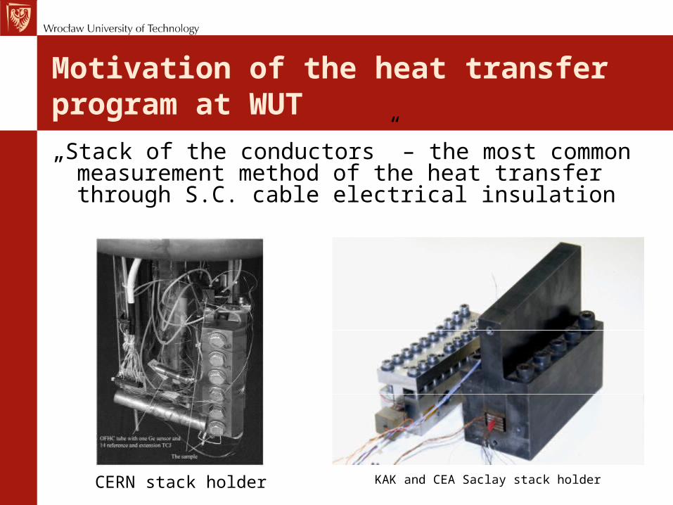
Motivation of the heat transfer program at WUT
„Stack of the conductors” – the most common measurement method of the heat transfer through S.C. cable electrical insulation
CERN stack holder KAK and CEA Saclay stack holder
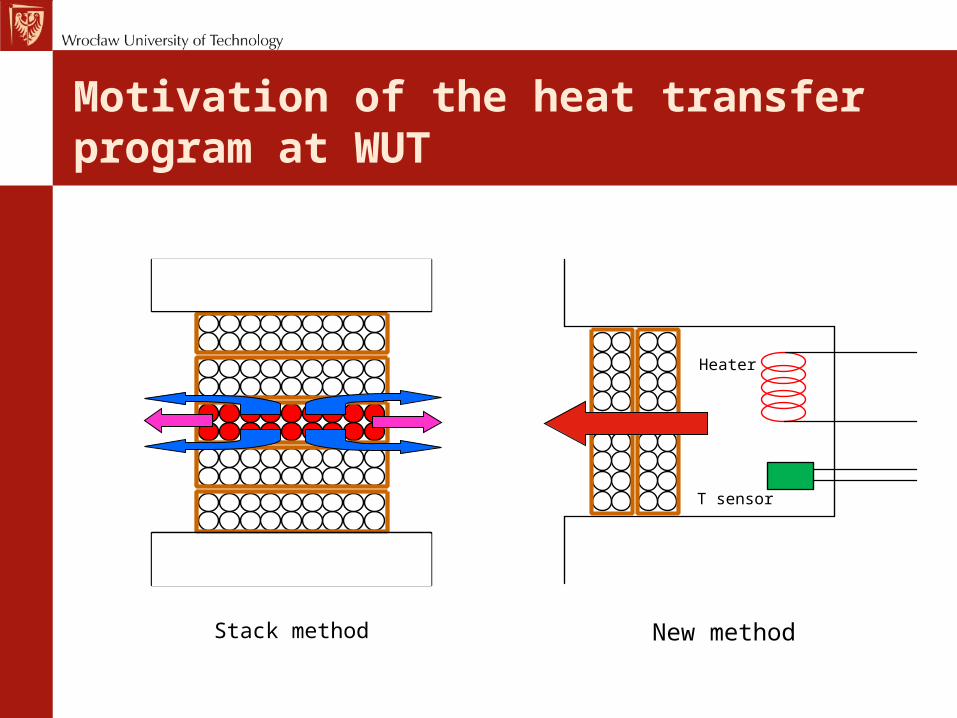
Motivation of the heat transfer program at WUT
Stack method New method
Heater
T sensor
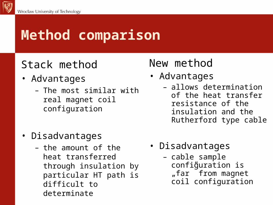
Method comparison
Stack method• Advantages
– The most similar with real magnet coil configuration
• Disadvantages– the amount of the heat
transferred through insulation by particular HT path is difficult to determinate
New method• Advantages
– allows determination of the heat transfer resistance of the insulation and the Rutherford type cable
• Disadvantages– cable sample
configuration is „far” from magnet coil configuration
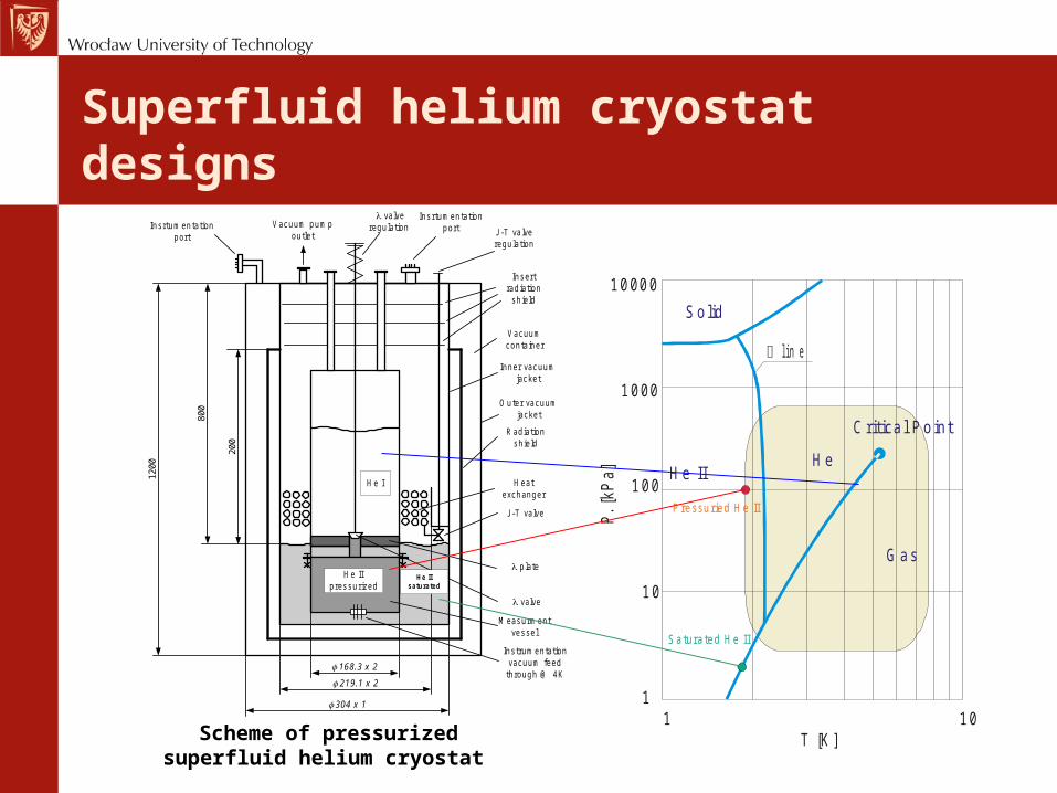
Superfluid helium cryostat designs
He I
He IIpressurized
Radiationshield
Vacuumcontainer
Vacuum pumpoutlet J-T valve
regulation
J-T valve
Heatexchanger
valve
plate
Measurmentvessel
1200
800
168.3 x 2
219.1 x 2
He IIsaturated
304 x 1
200
valveregulation
Insertradiation
shield
Instrumentationvacuum feed
through @ 4K
Insrtumentationport
Insrtumentationport
Inner vacuumjacket
Outer vacuumjacket
Scheme of pressurized superfluid helium cryostat
Solid
Critica l Point
He IIHe
1 10T [K ]
1
10
100
1000
10000
P. [
kPa
]
Pressu ried H e II
Saturated He II
G as
line
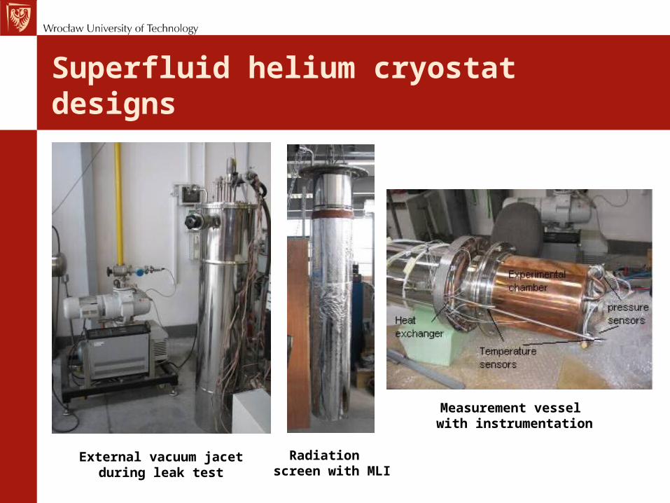
Superfluid helium cryostat designs
Radiation screen with MLI
Measurement vessel with instrumentation
External vacuum jacetduring leak test
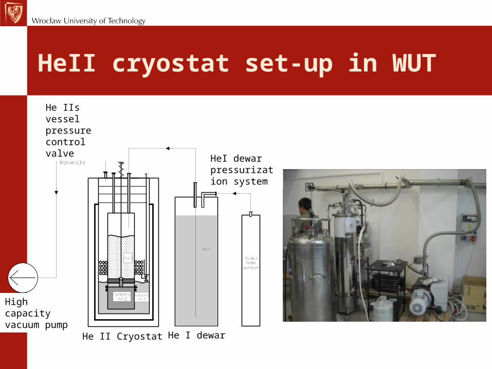
HeII cryostat set-up in WUT
He I
SprężonyHe II
NasyconyHe II
He I
Butla z helem
gazowym
Pompa o wysokiej wydajności
Zawór regulacyjny
Zbiornik helowyDwuobjętościowy kriostat helowyHe II Cryostat He I dewar
HeI dewar pressurization system
He IIs vessel pressure control valve
High capacity vacuum pump
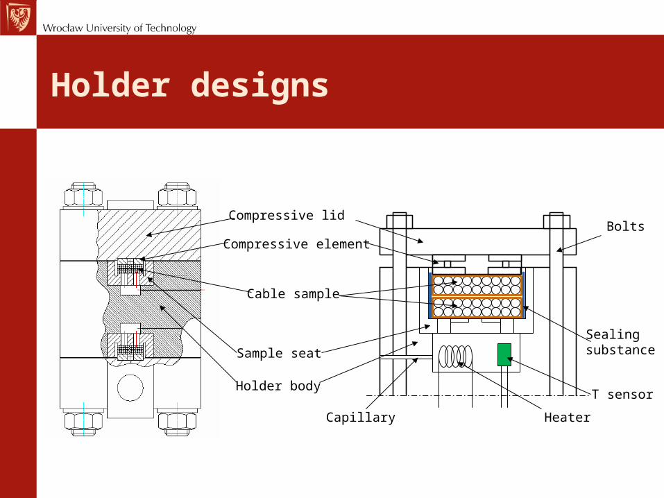
Holder designs
Cable sample
T sensor
Heater
Holder body
Capillary
Compressive lid
Compressive element
Sealing substanceSample seat
Bolts
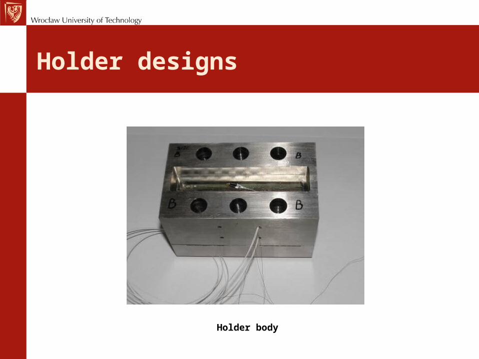
Holder designs
Holder body
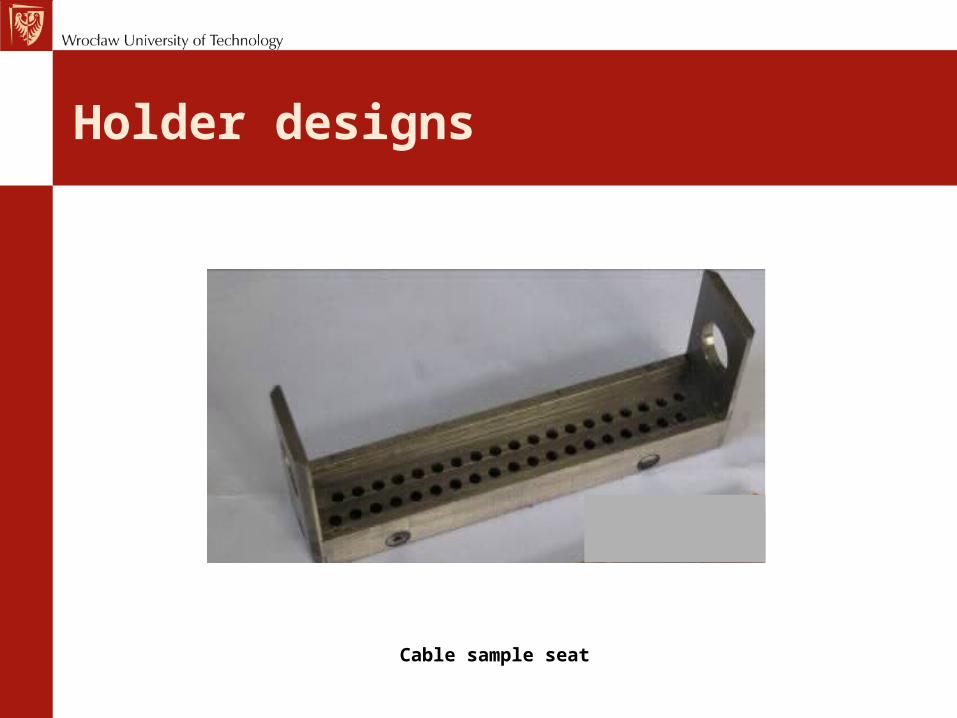
Holder designs
Cable sample seat
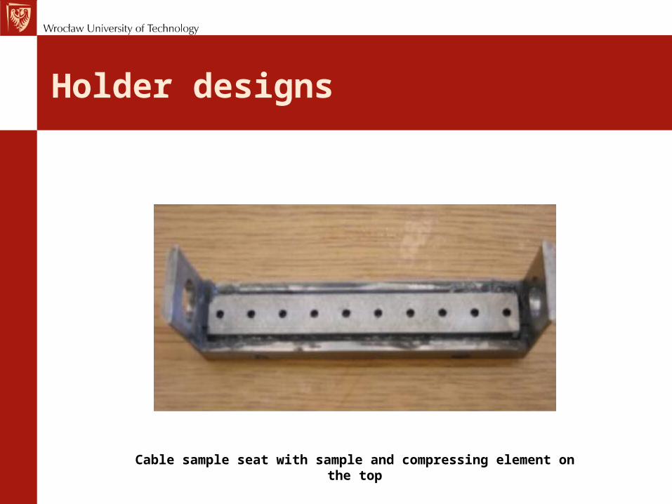
Holder designs
Cable sample seat with sample and compressing element on the top
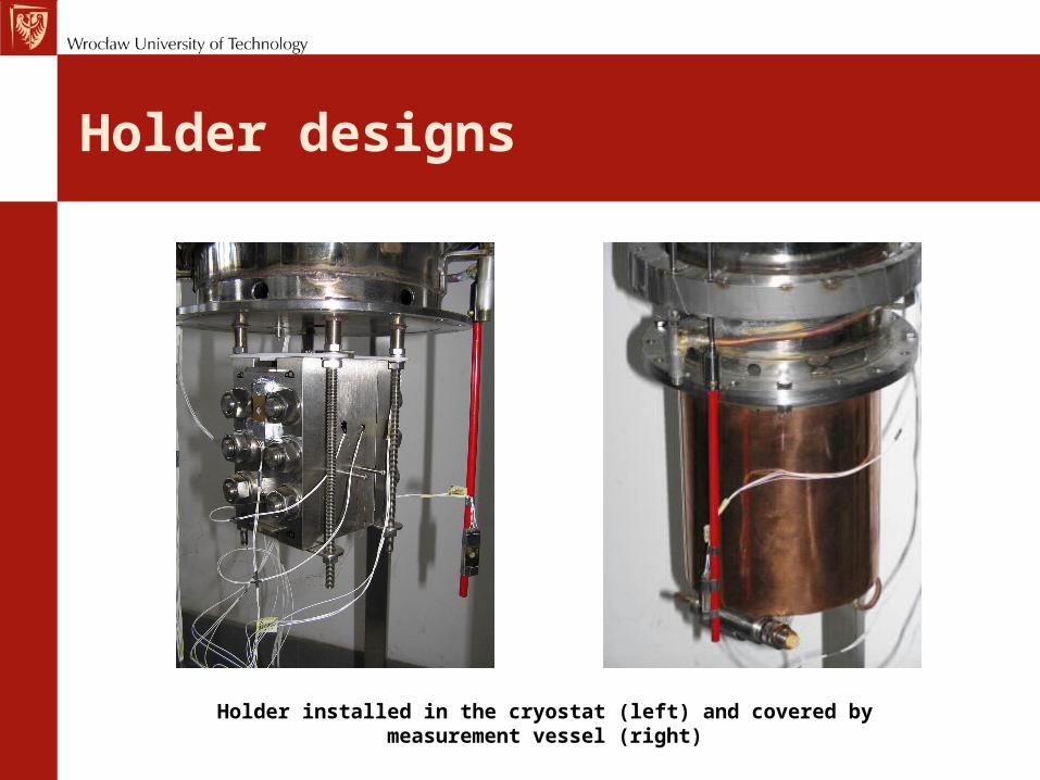
Holder designs
Holder installed in the cryostat (left) and covered by measurement vessel (right)
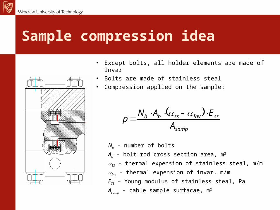
Sample compression idea
• Except bolts, all holder elements are made of Invar• Bolts are made of stainless steal• Compression applied on the sample:
samp
ssInvssbb
A
EANp
Nb – number of bolts
Ab – bolt rod cross section area, m2
SS – thermal expension of stainless steal, m/m
Inv – thermal expension of invar, m/m
ESS – Young modulus of stainless steal, Pa
Asamp – cable sample surfacae, m2
Sample compression idea
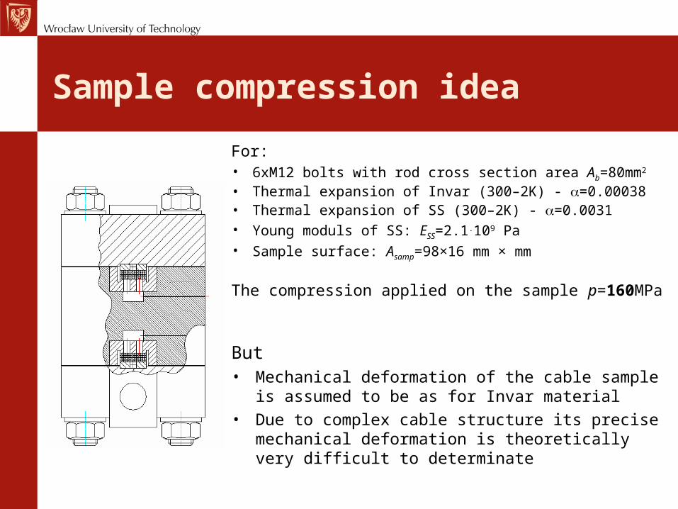
For:• 6xM12 bolts with rod cross section area Ab=80mm2 • Thermal expansion of Invar (300–2K) - =0.00038• Thermal expansion of SS (300–2K) - =0.0031• Young moduls of SS: ESS=2.1.109 Pa• Sample surface: Asamp=98×16 mm × mm
The compression applied on the sample p=160MPa
But• Mechanical deformation of the cable sample is
assumed to be as for Invar material• Due to complex cable structure its precise
mechanical deformation is theoretically very difficult to determinate
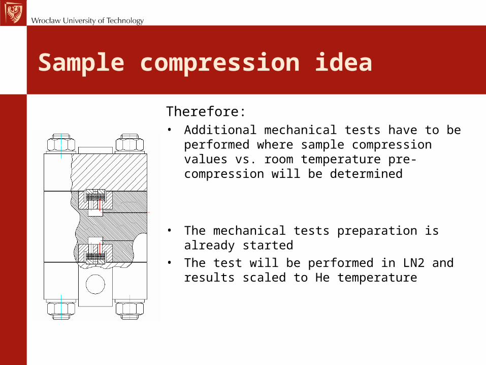
Sample compression idea
Therefore:• Additional mechanical tests have to be
performed where sample compression values vs. room temperature pre-compression will be determined
• The mechanical tests preparation is already started
• The test will be performed in LN2 and results scaled to He temperature
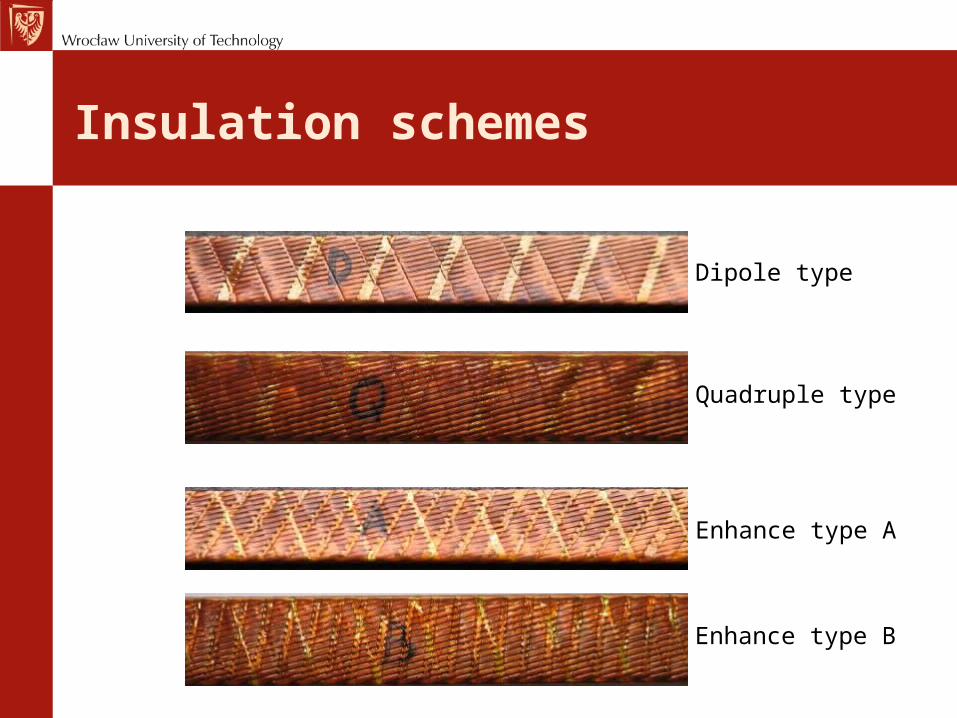
Insulation schemes
Dipole type
Quadruple type
Enhance type A
Enhance type B

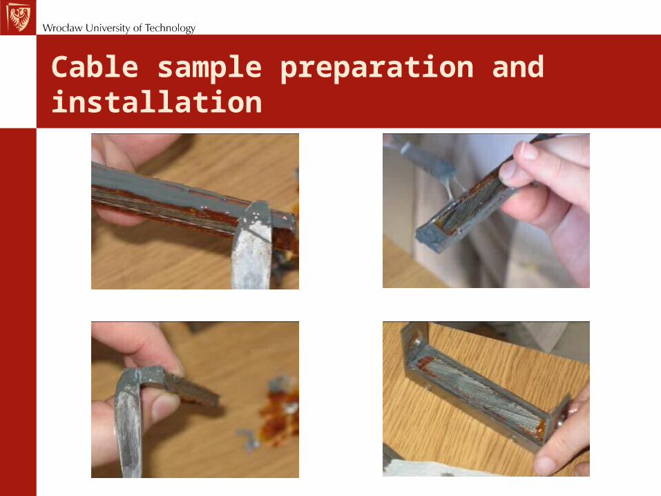
Cable sample preparation and installation
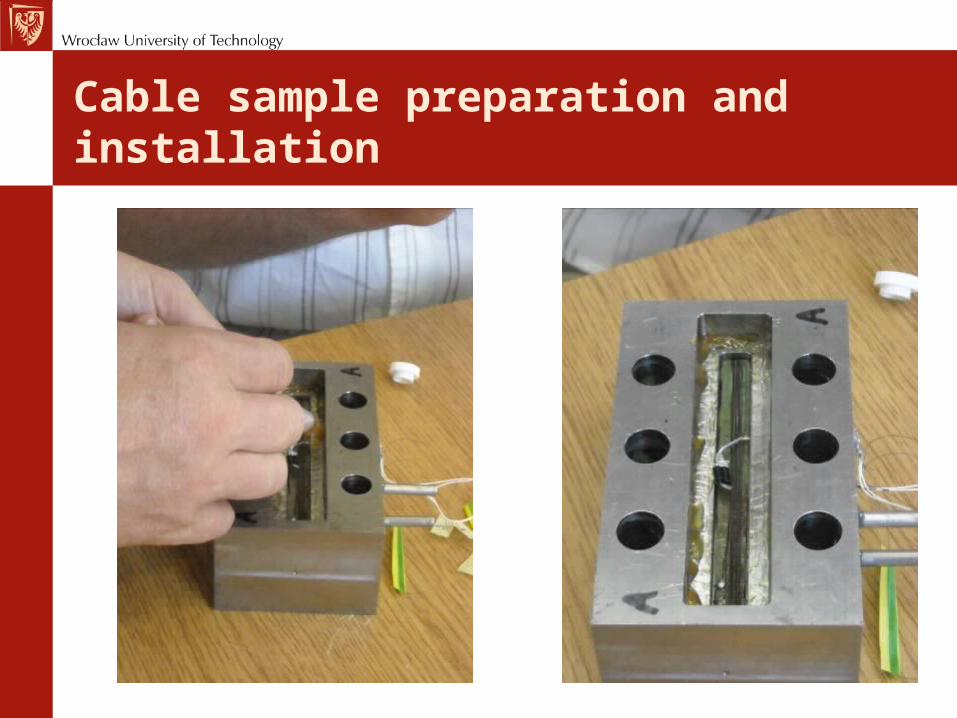
Cable sample preparation and installation
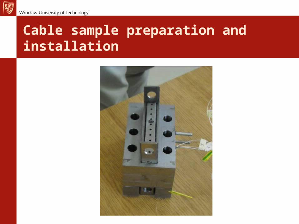
Cable sample preparation and installation
Cable sample preparation and installation
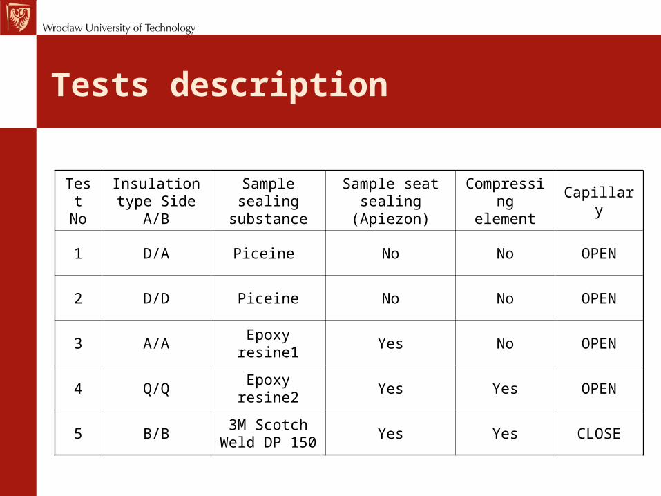
Tests description
Test No
Insulation type Side
A/B
Sample sealing
substance
Sample seat sealing
(Apiezon)
Compressing element
Capillary
1 D/A Piceine No No OPEN
2 D/D Piceine No No OPEN
3 A/AEpoxy
resine1Yes No OPEN
4 Q/QEpoxy
resine2Yes Yes OPEN
5 B/B3M Scotch
Weld DP 150Yes Yes CLOSE
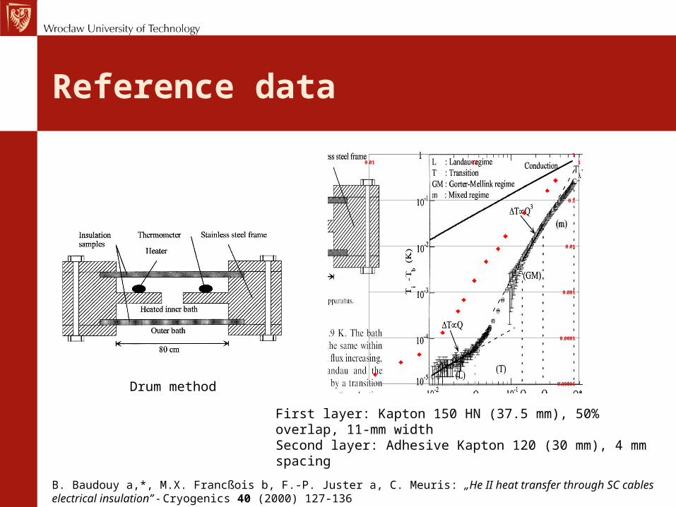
Reference data
0.00001
0.0001
0.001
0.01
0.1
1
0.01 0.1 1
B. Baudouy a,*, M.X. Francßois b, F.-P. Juster a, C. Meuris: „He II heat transfer through SC cables electrical insulation” - Cryogenics 40 (2000) 127-136
First layer: Kapton 150 HN (37.5 mm), 50% overlap, 11-mm widthSecond layer: Adhesive Kapton 120 (30 mm), 4 mm spacing
Drum method
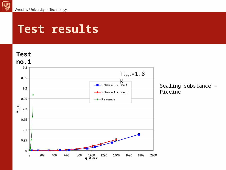
Test results
0
0.05
0.1
0.15
0.2
0.25
0.3
0.35
0.4
0 200 400 600 800 1000 1200 1400 1600 1800 2000q, W/m2
DT
, K
Scheme D - Side A
Scheme A - Side B
Reference
Test no.1
Sealing substance – Piceine
Tbath=1.8K
Test results
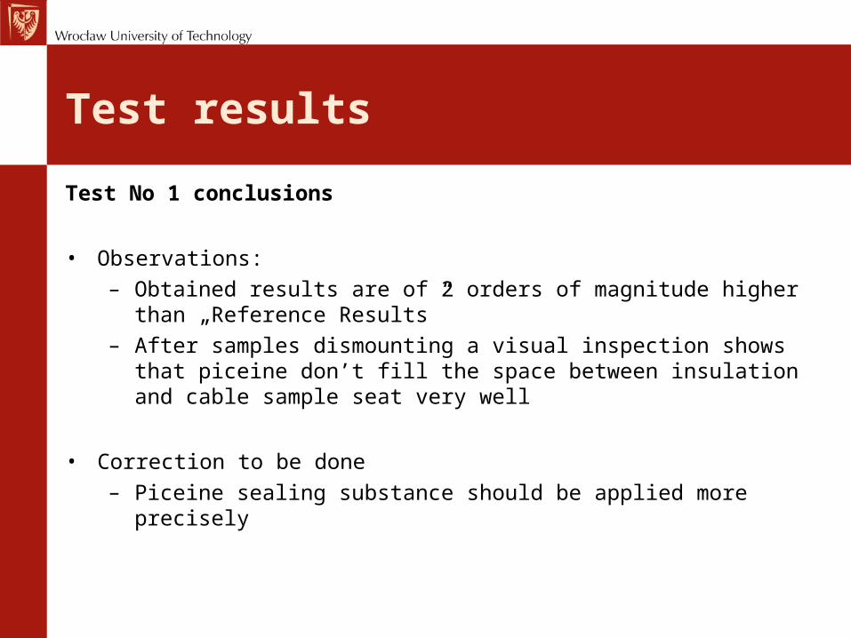
Test No 1 conclusions
• Observations:– Obtained results are of 2 orders of magnitude higher than
„Reference Results”– After samples dismounting a visual inspection shows that
piceine don’t fill the space between insulation and cable sample seat very well
• Correction to be done– Piceine sealing substance should be applied more precisely
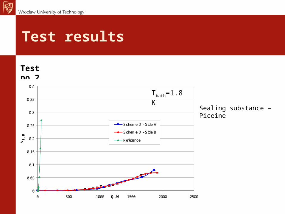
Test results
Test no.2
0
0.05
0.1
0.15
0.2
0.25
0.3
0.35
0.4
0 500 1000 1500 2000 2500Q, W
DT
, K
Scheme D - Side A
Scheme D - Side B
Reference
Sealing substance – Piceine
Tbath=1.8K
Test results
Test No 2 conclusions
• Observations:– Obtained results are still 2 order of magnitude higher than
„Reference Results”– After samples dismounting a visual inspection shows that
piceine don’t fill the space between insulation and cable sample seat very well
• Correction to be done– Piceine sealing substance should be substitute with some epoxy
resin– Sealing between sample seat and the holder body should be
created. To allow disassemble of the sample seat from the holder body after test an Apiezon vacuum grease have been chosen
Test results
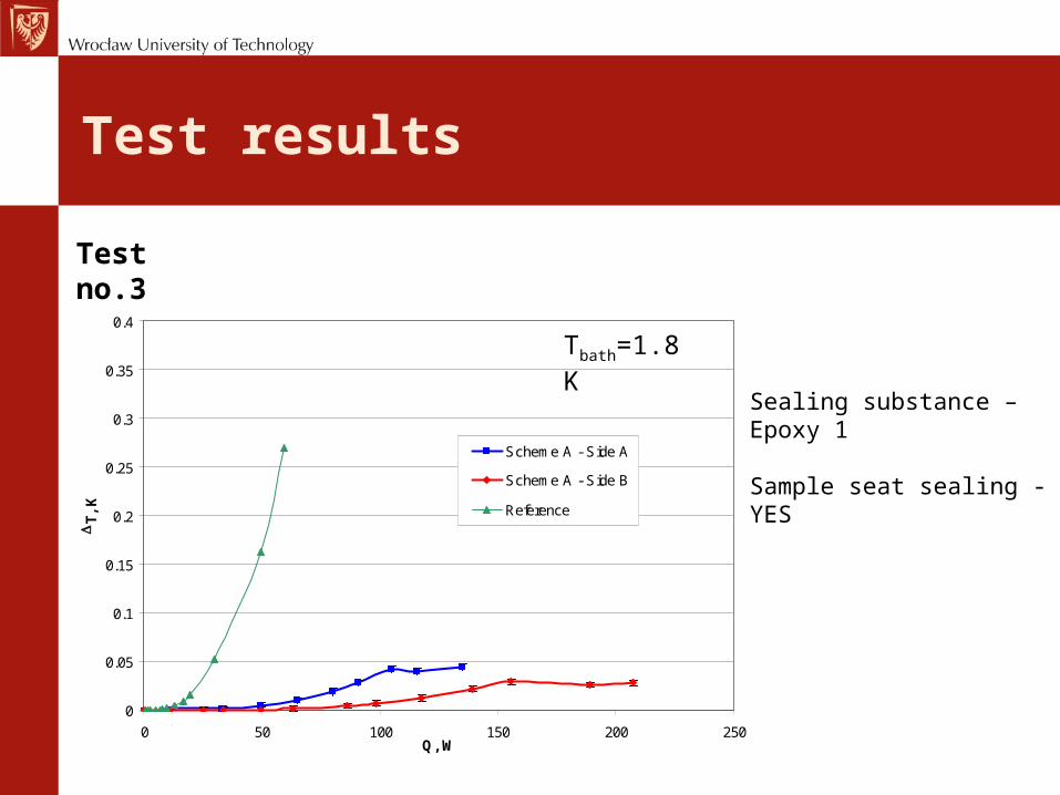
Test no.3
Sealing substance – Epoxy 1
Sample seat sealing - YES
0
0.05
0.1
0.15
0.2
0.25
0.3
0.35
0.4
0 50 100 150 200 250Q, W
DT
, K
Scheme A - Side A
Scheme A - Side B
Reference
Tbath=1.8K
Test results
Test No 3 conclusions
• Observations:
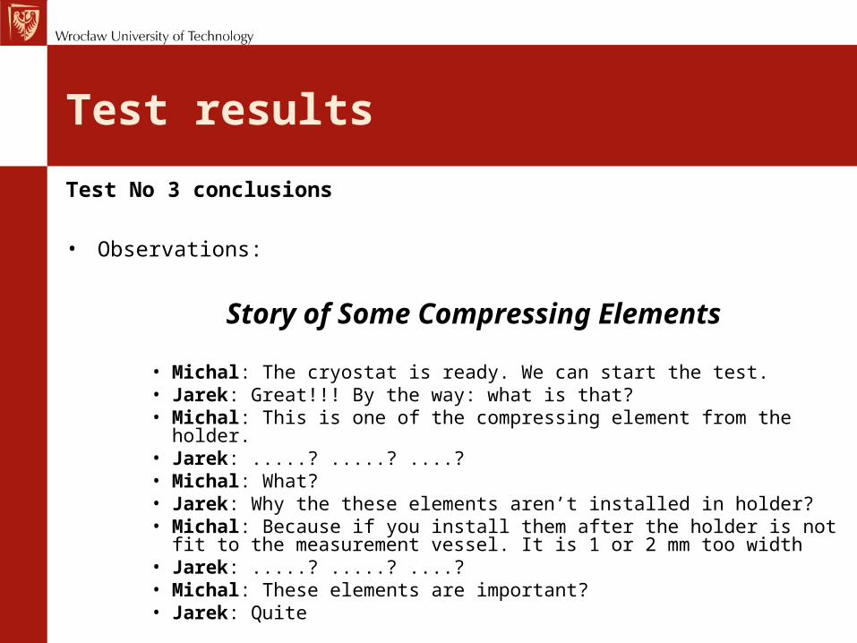
Story of Some Compressing Elements
• Michal: The cryostat is ready. We can start the test.• Jarek: Great!!! By the way: what is that?• Michal: This is one of the compressing element from the holder.• Jarek: .....? .....? ....? • Michal: What?• Jarek: Why the these elements aren’t installed in holder?• Michal: Because if you install them after the holder is not fit to the
measurement vessel. It is 1 or 2 mm too width• Jarek: .....? .....? ....?• Michal: These elements are important?• Jarek: Quite
Test results
Test No 3 conclusions
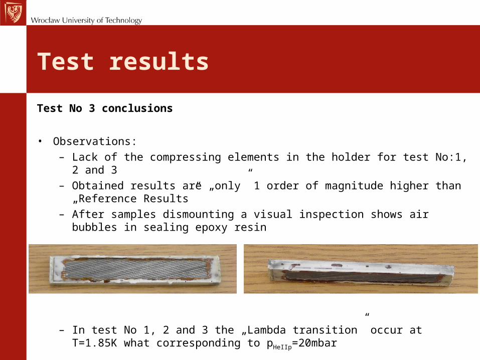
• Observations:– Lack of the compressing elements in the holder for test No:1, 2
and 3– Obtained results are „only” 1 order of magnitude higher than
„Reference Results”– After samples dismounting a visual inspection shows air bubbles in
sealing epoxy resin
– In test No 1, 2 and 3 the „Lambda transition” occur at T=1.85K what corresponding to pHeIIp=20mbar
Test results
Test No 3 conclusions
• Correction to be done– Reducing of the compression elements to high allows the holder
installation in the measurement vessel– Test the other type of the epoxy resin– Solve the problem of „low temperature lambda transition”
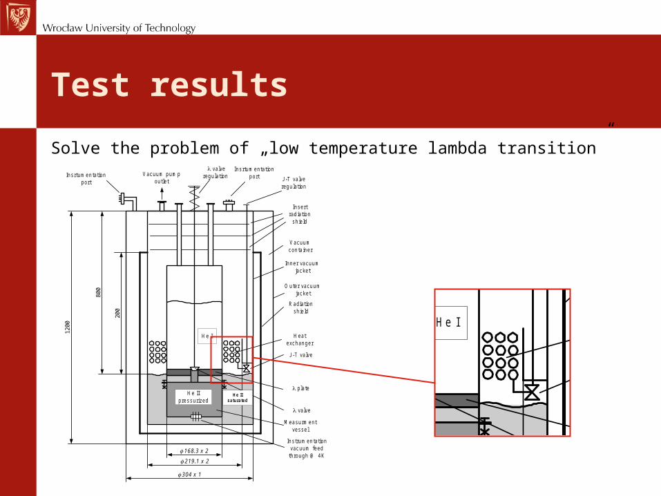
Test results
Solve the problem of „low temperature lambda transition”
He I
He IIpressurized
Radiationshield
Vacuumcontainer
Vacuum pumpoutlet J-T valve
regulation
J-T valve
Heatexchanger
valve
plate
Measurmentvessel
1200
800
168.3 x 2
219.1 x 2
He IIsaturated
304 x 1
200
valveregulation
Insertradiation
shield
Instrumentationvacuum feed
through @ 4K
Insrtumentationport
Insrtumentationport
Inner vacuumjacket
Outer vacuumjacket
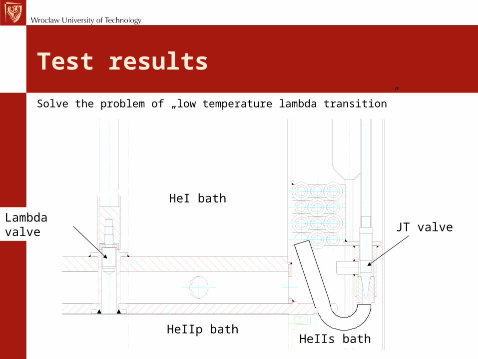
Test results
HeI bath
HeIIp bathHeIIs bath
Solve the problem of „low temperature lambda transition”
Lambda valveJT valve
Test results
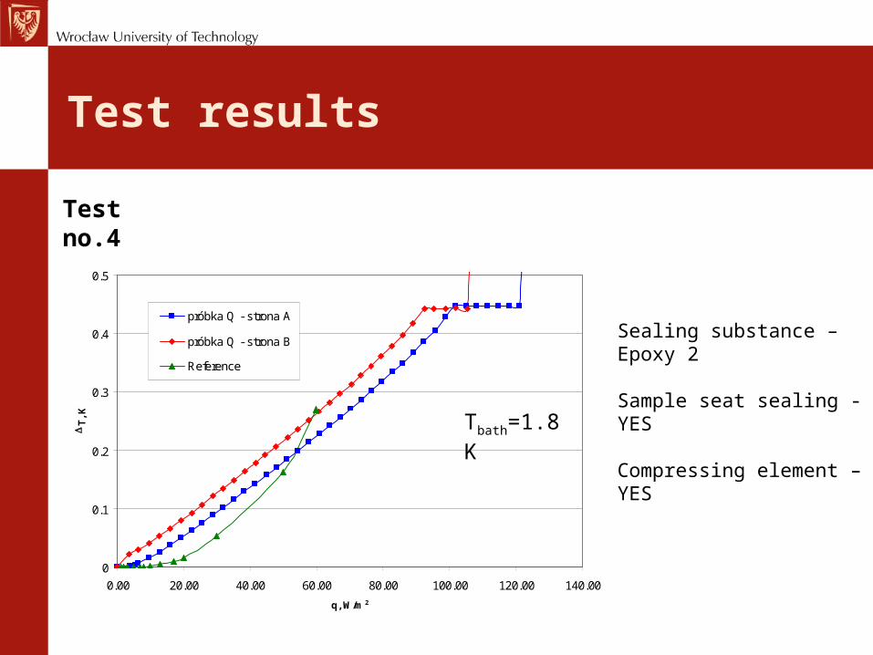
Test no.4
Sealing substance – Epoxy 2
Sample seat sealing - YES
Compressing element – YES
0
0.1
0.2
0.3
0.4
0.5
0.00 20.00 40.00 60.00 80.00 100.00 120.00 140.00
q, W/m 2
DT
, K
próbka Q - strona A
próbka Q - strona B
Reference
Tbath=1.8K
Test results
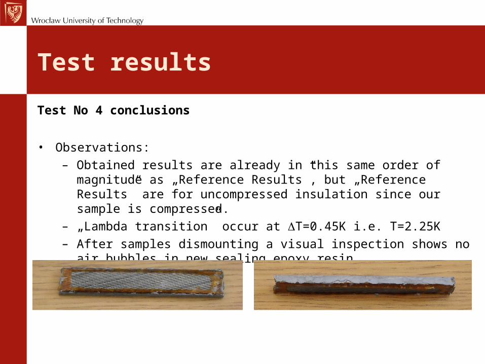
Test No 4 conclusions
• Observations:– Obtained results are already in this same order of magnitude as
„Reference Results”, but „Reference Results” are for uncompressed insulation since our sample is compressed.
– „Lambda transition” occur at DT=0.45K i.e. T=2.25K– After samples dismounting a visual inspection shows no air
bubbles in new sealing epoxy resin
Test results
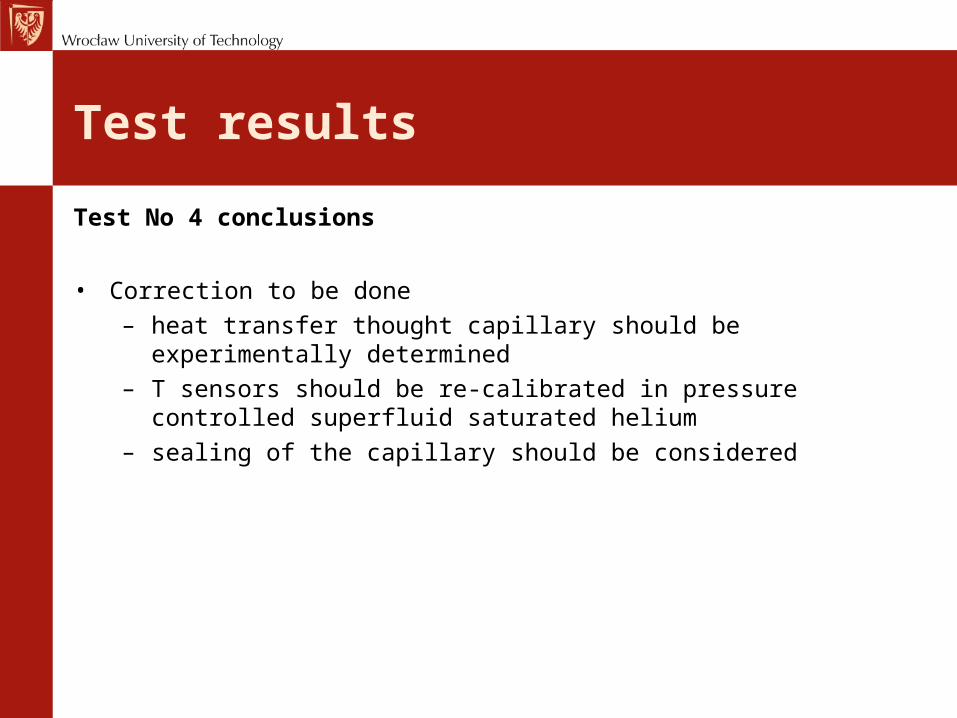
Test No 4 conclusions
• Correction to be done– heat transfer thought capillary should be experimentally
determined– T sensors should be re-calibrated in pressure controlled
superfluid saturated helium– sealing of the capillary should be considered
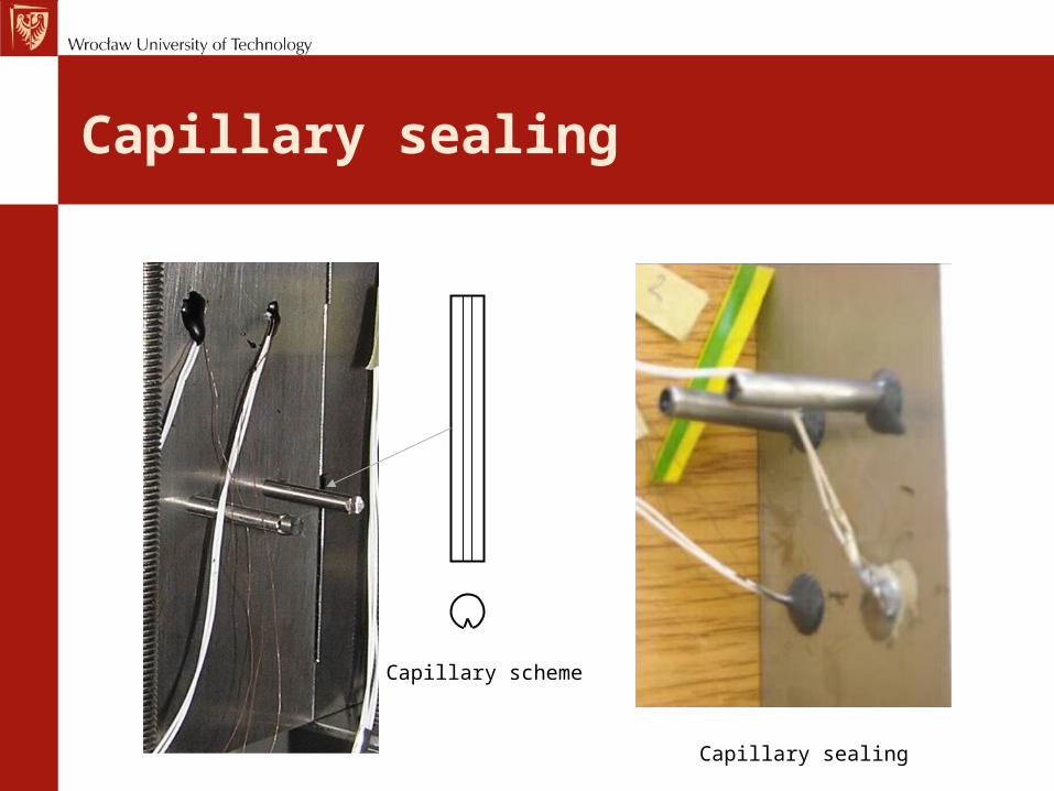
Capillary sealing
Capillary scheme
Capillary sealing
Test results
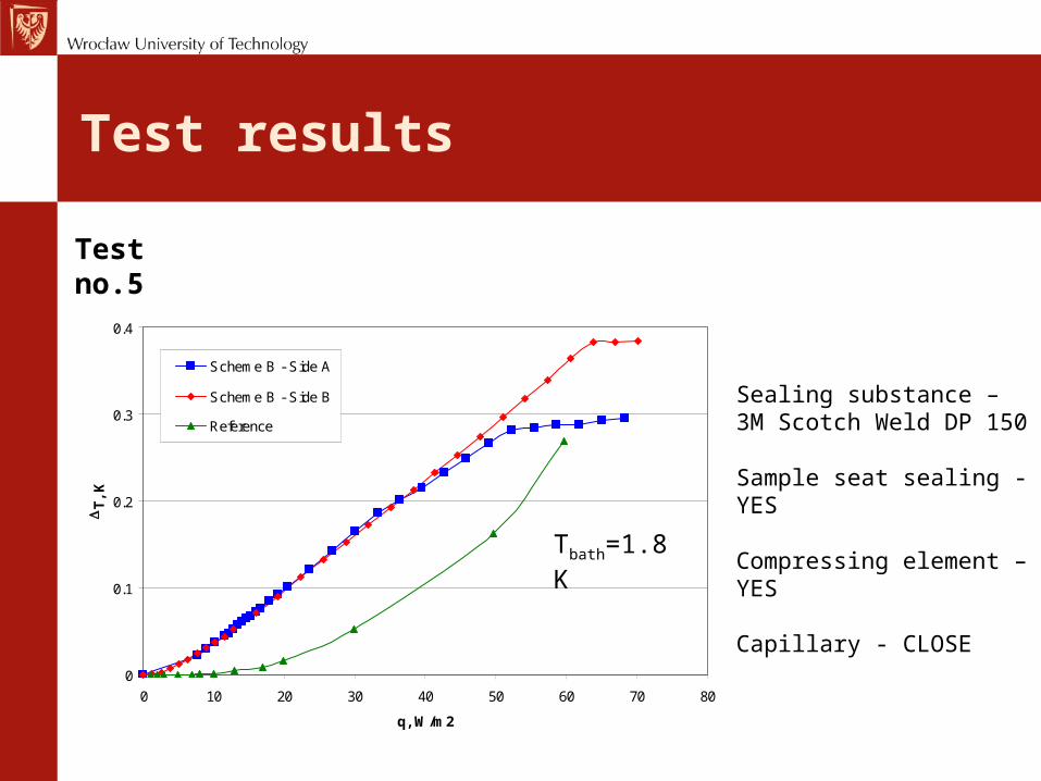
Test no.5
Sealing substance –3M Scotch Weld DP 150
Sample seat sealing - YES
Compressing element – YES
Capillary - CLOSE 0
0.1
0.2
0.3
0.4
0 10 20 30 40 50 60 70 80
q, W/m2
DT
, K
Scheme B - Side A
Scheme B - Side B
Reference
Tbath=1.8K
Test results
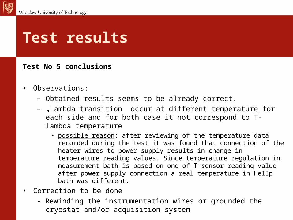
Test No 5 conclusions
• Observations:– Obtained results seems to be already correct. – „Lambda transition” occur at different temperature for each side
and for both case it not correspond to T-lambda temperature• possible reason: after reviewing of the temperature data recorded
during the test it was found that connection of the heater wires to power supply results in change in temperature reading values. Since temperature regulation in measurement bath is based on one of T-sensor reading value after power supply connection a real temperature in HeIIp bath was different.
• Correction to be done- Rewinding the instrumentation wires or grounded the cryostat
and/or acquisition system
Conclusion
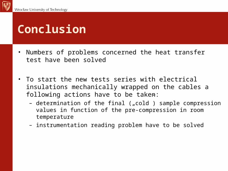
• Numbers of problems concerned the heat transfer test have been solved
• To start the new tests series with electrical insulations mechanically wrapped on the cables a following actions have to be taken:– determination of the final („cold”) sample compression values in
function of the pre-compression in room temperature– instrumentation reading problem have to be solved