Embed Size (px)
Citation preview

LevelOne User Manual
Ver. 1.0.0-0815
WUA-0615
N_Max Wireless USB Adapter

ii
Safety FCC WARNING
This equipment has been tested and found to comply with the limits for a Class B digital device, pursuant to Part 15 of the FCC Rules. These limits are designed to provide reasonable protection against harmful interference in a residential installation.
This equipment generates, uses and can radiate radio frequency energy and, if not installed and used in accordance with the instructions, may cause harmful interference to radio communications. However, there is no guarantee that interference will not occur in a particular installation. If this equipment does cause harmful interference to radio or television reception, which can be determined by turning the equipment off and on, the user is encouraged to try to correct the interference by one of the following measures:
Reorient or relocate the receiving antenna.
Increase the separation between the equipment and receiver.
Connect the equipment into an outlet on a circuit different from that to which the receiver is connected.
Consult the dealer or an experienced radio/TV technician for help.
To assure continued compliance, any changes or modifications not expressly approved by the party responsible for compliance could void the user's authority to operate this equipment. (Example - use only shielded interface cables when connecting to computer or peripheral devices).
FCC Radiation Exposure Statement
This equipment complies with FCC RF radiation exposure limits set forth for an uncontrolled environment. This equipment should be installed and operated with a minimum distance of 20 centimeters between the radiator and your body.
This device complies with Part 15 of the FCC Rules. Operation is subject to the following two conditions:
(1) This device may not cause harmful interference, and
(2) This device must accept any interference received, including interference that may cause undesired operation.
This transmitter must not be co-located or operating in conjunction with any other antenna or transmitter.
CE Marking Warning
Digital Data Communications, declares that this product (Model-no. WUA-0615) is in compliance with the essential
requirements and other relevant provisions of Directive 1999/5/EC.
The CE-Declaration of Conformity can be downloaded at:
http://www.levelone.eu/support.php

iii
Table of Content
TABLE OF CONTENT ................................................................................................................ III
1. INTRODUCTION ..................................................................................................................... 4
1.1 USER MANUAL OVERVIEW ...................................................................................................... 4
2. UNPACKING AND SETUP ...................................................................................................... 5
2.1 FEATURES ............................................................................................................................. 5
2.2 PACKAGE CONTENTS ............................................................................................................. 5
2.3 SETUP .................................................................................................................................. 5
3. HARDWARE INSTALLATION ................................................................................................ 6
3.1 INSTALLATION PROCEDURE FOR USB ADAPTER ....................................................................... 6
3.2 LED INDICATOR ..................................................................................................................... 6
3.3 CHECK THE INSTALLATION ...................................................................................................... 7
3.4 WPS BUTTON ....................................................................................................................... 7
4. SOFTWARE INSTALLATION ................................................................................................. 8
4.1 WINDOWS XP UTILITY INSTALLATION ....................................................................................... 8
4.2 WINDOWS VISTA UTILITY INSTALLATION ................................................................................. 12
5. WIRELESS UTILITY CONFIGURATION (FOR WINDOWS XP AND VISTA) ....................... 16
5.1 PROFILE.............................................................................................................................. 16
5.2 NETWORK ........................................................................................................................... 21
5.3 ADVANCED .......................................................................................................................... 23
5.4 STATISTICS ......................................................................................................................... 24
5.5 WMM ................................................................................................................................. 25
5.6 WPS .................................................................................................................................. 26
5.7 RADIO SETTING ................................................................................................................... 28
5.8 ABOUT ................................................................................................................................ 28
6. NETWORK PLANNING ......................................................................................................... 29
7. TECHNICAL SPECIFICATIONS ........................................................................................... 31

4
1. Introduction
Congratulations on your purchase of LevelOne N_Max Wireless USB Adapter.
This manual helps to get familiar with the LevelOne N_Max Wireless LAN Adapter. This manual
contains detailed instructions in operation of this product. Please keep this manual for future
reference.
With a Wireless LAN Adapter, a laptop computer or a station can communicate with another
computer in a wireless way. Easy-to-use utilities are bundled with Wireless LAN Adapter for
configuration, monitoring, and diagnosis purposes.
Wireless LAN Adapter can wirelessly transmit and receive data, with the Wireless LAN Adapter, you
can locate your Notebook PC or station wherever you want without wires and cables.
Wireless LAN Adapter provides users with an access to real-time information anywhere in their
organization. The mobility provides productivity and service, which are not available under wired
networks. The Wireless LAN Adapter configuration is easy to change from peer-to-peer networks,
suitable for a small number of users, to full infrastructure networks of thousands of users that allow
roaming around a broad area.
1.1 User Manual Overview
Introduction Describes N_Max Wireless USB Adapter.
Unpacking and Setup Helps user to get started with the basic installation of the N_Max Wireless USB Adapter.
Hardware Installation Describes the LED indicators of the N_Max Wireless USB Adapter.
Software Installation Tells how to setup the driver and the utility setting.
Technical Specifications Lists the technical (general, physical and environmental) specifications of the N_Max Wireless USB Adapter.

5
2. Unpacking and Setup
This chapter provides the package contents and setup information for the N_Max Wireless USB
Adapter.
2.1 Features
Extended and high-speed wireless connectivity with N_Max (Draft n) wireless technology
Hardware Push Button for Wi-Fi Protected Setup
Backward compliant with IEEE802.11g and 11b standards
Operates on the 2.4GHz frequency band
Supports 64/128-bit WEP ,WPA and WPA2 encryption for high level security
Supports Window 2000/XP/Vista
2.2 Package Contents
Open the box of the N_Max Wireless USB Adapter and carefully unpack it. The box should contain
the following items:
WUA-0615 N_Max Wireless USB Adapter
Quick Installation Guide
CD Manual/Driver/Utility
If any item is found missing or damaged, please contact your local reseller for replacement.
2.3 Setup
The setup of the Wireless USB Adapter can be performed using the following steps:
Visually inspect the USB Adapter and make sure that it is fully plugged in to the USB port.
Make sure that there is a well environment that there is no much intrusion to have a better
connection.

6
3. Hardware Installation
3.1 Installation Procedure for USB Adapter
You should install the supplied software BEFORE inserting the Wireless USB Adapter when using
Windows 2000, XP or Vista.
Note
The following installation was operated under Windows XP and Vista.
(Procedures are similar for Windows 2000.)
If you have installed the Wireless Adapter driver & utility before, please uninstall
the old version first.
3.2 LED Indicator
The Wireless Adapter has Link and PWR LED.
LED Status Description
PWR On Indicates the power is on.
Off Indicates the power is off
LINK On/Flashing Indicates the power is on, and the 802.11b/g/n radio is enabled.
Flashing indicates wireless network activity.
Off Indicates the power is off, or the 802.11b/g/n radio is disabled

7
3.3 Check the installation
The LEDs of the Wireless USB Adapter are clearly visible and the status of the network link can be
seen instantly:
1. Once the device is plugged to the station‟s USB port, the PWR LED of the Wireless USB Adapter
will light up indicating a normal status with power.
2. While the Wireless USB Adapter linked up and transmitting data to the Access Point or to other
Wireless LAN station, the LINK LED will start alternate blinking.
3.4 WPS Button
Use the WPS button on the Wireless USB Adapter to automatically connect devices to the network.
Within two minutes, press the physical or virtual button on wireless client devices to enable them to
join the WLAN.
The WPS configuration process may be initiated on any device and there is no restriction to the order
in which buttons are pressed.
Any WPS-compatible devices could unintentionally join the WLAN if they are within range during the
two-minute set up period after the WPS button is pressed.
For more details about Wi-Fi Protected Setup, please refer to —WPS Button

8
4. Software Installation
This section will lead you to install the driver and utility of the N_Max Wireless USB Adapter.
4.1 Windows XP Utility Installation
1. Insert the N_Max Wireless USB Adapter Utility CD into the computer and then the Auto-run
screen will appear. Alternatively, open a file browser and double click on the autorun.exe file
located in the CD directory.
2. Click “Utility” to install the driver and utility and the install wizard will begin installing the software.
Follow the install wizard instructions to complete the installation.
3. Follow the Install Shield Wizard Instructions. Click “Next” to continue and follow the on-screen
instruction to finish it.
9
10
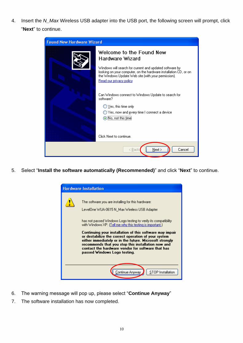
4. Insert the N_Max Wireless USB adapter into the USB port, the following screen will prompt, click
“Next” to continue.
5. Select “Install the software automatically (Recommended)” and click “Next” to continue.
6. The warning message will pop up, please select “Continue Anyway”
7. The software installation has now completed.

11
The installation program will help you to setup the Wireless LAN utility. Be noted that the Windows
XP has its own Wireless Utility; you can either use the utility of Windows XP or the provided
utility.
When the Wireless LAN utility is installed properly, you will see the icon on the Windows task bar.
The user can configure the wireless settings using the Wireless USB Adapter Configuration Utility.
Double-click the utility icon that appears in the taskbar
When the icon in the toolbar represents in full blue color then the signal strength has an excellent
performance with the AP, if it represents in half blue color then the signal strength has a fair
performance with the AP, and if the icon represents in low blue, then the signal strength has a worst
performance with the wireless station.
Excellent Wireless Signal Strength
Adequate Wireless Signal Strength
Low Wireless Signal Strength
Wireless Card inactive

12
4.2 Windows Vista Utility Installation
1. Insert the N_Max Wireless USB Adapter Utility CD into the computer and then the Auto-run
screen will appear. Alternatively, open a file browser and double click on the autorun.exe file
located in the CD directory.
2. Click “Utility” to install the driver and utility and the install wizard will begin installing the software.
Follow the install wizard instructions to complete the installation.
3. Follow the Install Shield Wizard Instructions. Click “Next” to continue and follow the on-screen
instruction to finish it.
13
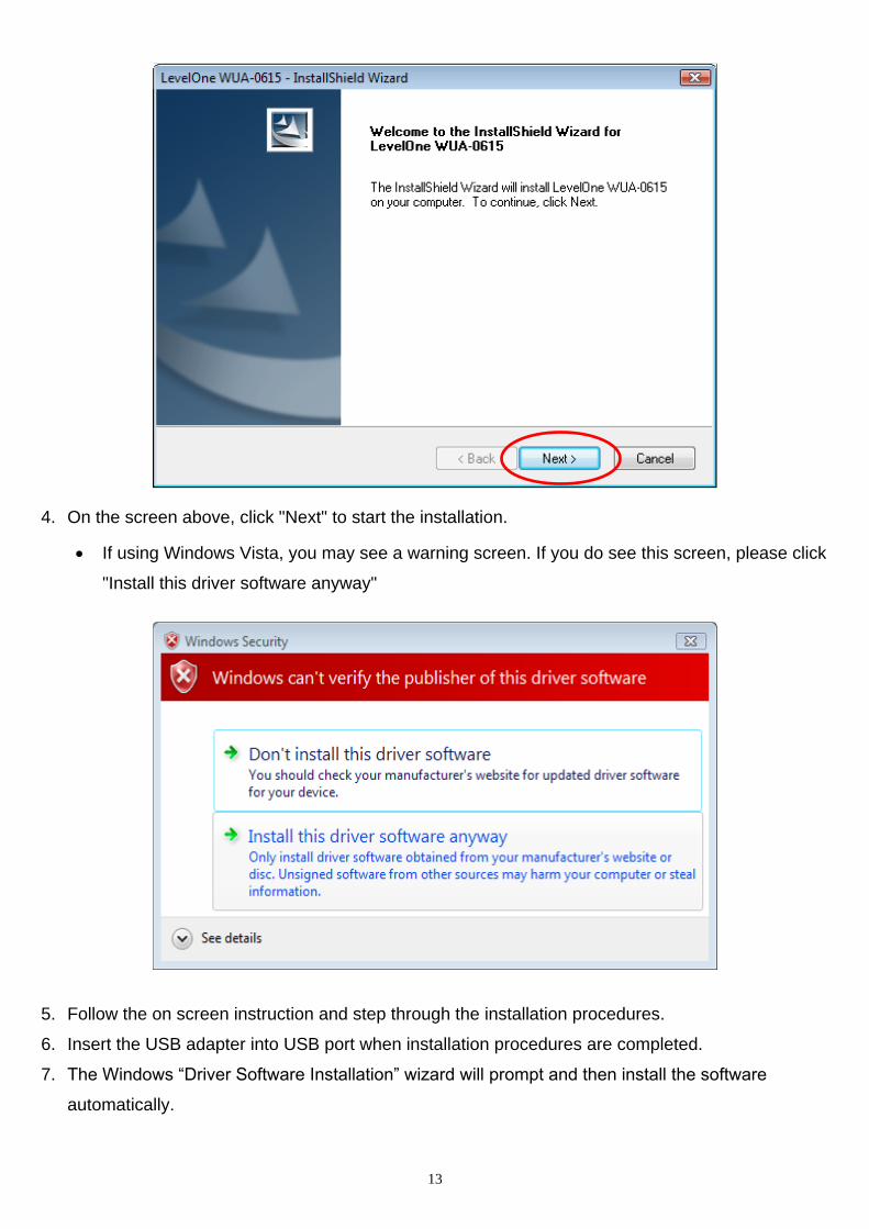
4. On the screen above, click "Next" to start the installation.
If using Windows Vista, you may see a warning screen. If you do see this screen, please click
"Install this driver software anyway"
5. Follow the on screen instruction and step through the installation procedures.
6. Insert the USB adapter into USB port when installation procedures are completed.
7. The Windows “Driver Software Installation” wizard will prompt and then install the software
automatically.

14
8. When the Windows wizard is complete, you will now have a new icon on your desktop and in your
system tray.
The installation program will help you to setup the Wireless LAN utility. Be noted that the Windows
Vista has its own Wireless Utility; you can either use the utility of Windows Vista or the
provided utility.
When the Wireless LAN utility is installed properly, you will see the icon on the Windows task bar.
The user can configure the wireless settings using the Wireless USB Adapter Configuration Utility.
Double-click the utility icon that appears in the taskbar
When the icon in the toolbar represents in full blue color then the signal strength has an excellent
performance with the AP, if it represents in half blue color then the signal strength has a fair
performance with the AP, and if the icon represents in low blue, then the signal strength has a worst
performance with the wireless station.
Excellent Wireless Signal Strength

15
Adequate Wireless Signal Strength
Low Wireless Signal Strength
Wireless Card inactive

16
5. Wireless Utility Configuration (For Windows XP and Vista)
5.1 Profile
The Profile List keeps a record of your favorite wireless settings at home, office, and other public hot-
spots. You can save multiple profiles, and activate the correct one at your preference. The following
Figure shows the basic profile section.
Profile Name: Profile Name: Name of profile, preset to PROF* (* indicate 1, 2, 3...).
SSID: The access point or Ad-hoc name.
Network Type: Indicates the networks type, including infrastructure and Ad-Hoc.
Authentication: Indicates the authentication mode used.
Encryption: Indicates the encryption Type used.
Use 802.1x: Shows if the 802.1x feature is used or not.
Tx Power: Transmitting power, the amount of power used by a radio transceiver to send the signal
out.
Cannel: Channel in use for Ad-Hoc mode.
Power Save Mode: Choose from CAM (Constantly Awake Mode) or Power Saving Mode.
RTS Threshold: Users can adjust the RTS threshold number by sliding the bar or keying in the value

17
directly.
Fragment Threshold: The user can adjust the Fragment threshold number by sliding the bar or key
in the value directly.
Add/Edit Profile: The user can add and edit the selected AP to the Profile setting. It will bring up a
profile page and save the user's setting to a new profile.
Delete Profile: The user can delete the selected AP from profile page.
Activate Profile: The user can activate the selected AP from profile page.
System Config.:
Profile Name: The user can chose any name for this profile, or use the default name defined by system.
SSID: The user can key in the intended SSID name or select one of the available APs from the drop-down list.
Power Save Mode: Choose CAM (Constantly Awake Mode) or Power Saving Mode.
Network Type: There are two types, infrastructure and 802.11 Ad-hoc mode. Under Ad-hoc mode, user can also choose the preamble type. The available preamble type includes auto and long. In addition, the channel field will be available for setup in Ad-hoc mode.
RTS Threshold: User can adjust the RTS threshold number by sliding the bar, or key in the value directly. The default value is 2347.
Fragment Threshold: User can adjust the Fragment threshold number by sliding the bar or key in the value directly. The default value is 2346.
Channel: Only available for setting under Ad-hoc mode. Users can choose the channel frequency to start their Ad-hoc network.

18
Auth. \ Encry.:
Authentication Type: There are 7 types of authentication modes which are open, Shared, LEAP, WPA and WPA-PSK, WPA2 and WPA2-PSK.
Encryption Type: For open and shared authentication mode, the selection of available encryption type are None and WEP. For WPA, WPA2, WPA-PSK and WPA2-PSK authentication mode, both TKIP and AES encryption is available.
WPA Pre-shared Key: This is the key shared between the AP and STA. For WPA-PSK and WPA2-PSK authentication mode, this field must be filled with a key between 8 and 32 characters in length.
WEP Key: Only valid when using WEP encryption algorithms. The key must be identical to the AP's key. There are several formats to enter the keys.
1. Hexadecimal - 40bits : 10 Hex characters.
2. Hexadecimal - 128bits : 26Hex characters.
3. ASCII - 40bits : 5 ASCII characters.
4. ASCII - 128bits : 13 ASCII characters.
802.1x Setting: 802.1x is used for authentication of the "WPA" and "WPA2" certificate by the server.
19
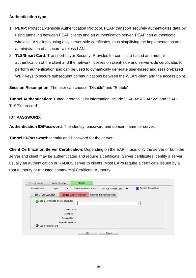
Authentication type:
1. PEAP: Protect Extensible Authentication Protocol. PEAP transport securely authenticates data by
using tunneling between PEAP clients and an authentication server. PEAP can authenticate
wireless LAN clients using only server-side certificates, thus simplifying the implementation and
administration of a secure wireless LAN.
2. TLS/Smart Card: Transport Layer Security. Provides for certificate-based and mutual
authentication of the client and the network. It relies on client-side and server-side certificates to
perform authentication and can be used to dynamically generate user-based and session-based
WEP keys to secure subsequent communications between the WLAN client and the access point.
Session Resumption: The user can choose "Disable" and "Enable".
Tunnel Authentication: Tunnel protocol, List information include "EAP-MSCHAP v2" and "EAP-
TLS/Smart card".
ID \ PASSWORD:
Authentication ID/Password: The identity, password and domain name for server.
Tunnel ID/Password: Identity and Password for the server.
Client Certification/Server Certification: Depending on the EAP in use, only the server or both the
server and client may be authenticated and require a certificate. Server certificates identify a server,
usually an authentication or RADIUS server to clients. Most EAPs require a certificate issued by a
root authority or a trusted commercial Certificate Authority.

20
Use certification chain: Place a check in this to enable the certificate use. Select the Certification
Authority from the drop-down list.
Server name: Enter the server name if not selected from the existing drop-down list above.
.

21
5.2 Network The network setting page allows you to set and save different wireless settings. You can activate the
suitable profile according to the environment where the wireless connection is used.
Sort by: Indicate that the AP list is sorted by SSID, Channel or Signal.
Show dBm: Show the dBm strength of the received signal.
Rescan: Issues a rescan command to the wireless NIC to update information on the surrounding
wireless network.
Add to Profile: Add the selected AP to the Profile setting. It will bring up a profile page and save the
user's setting to a new profile.
The Profile page is displayed for configuration:
Icon Indications Icons Description
Connection is successful
Network type is infrastructure mode
Network type is ad-hoc mode
Wireless network is security-enabled
The network supports 802.11b connections
The network supports 802.11g connections
The network supports 802.11n connections
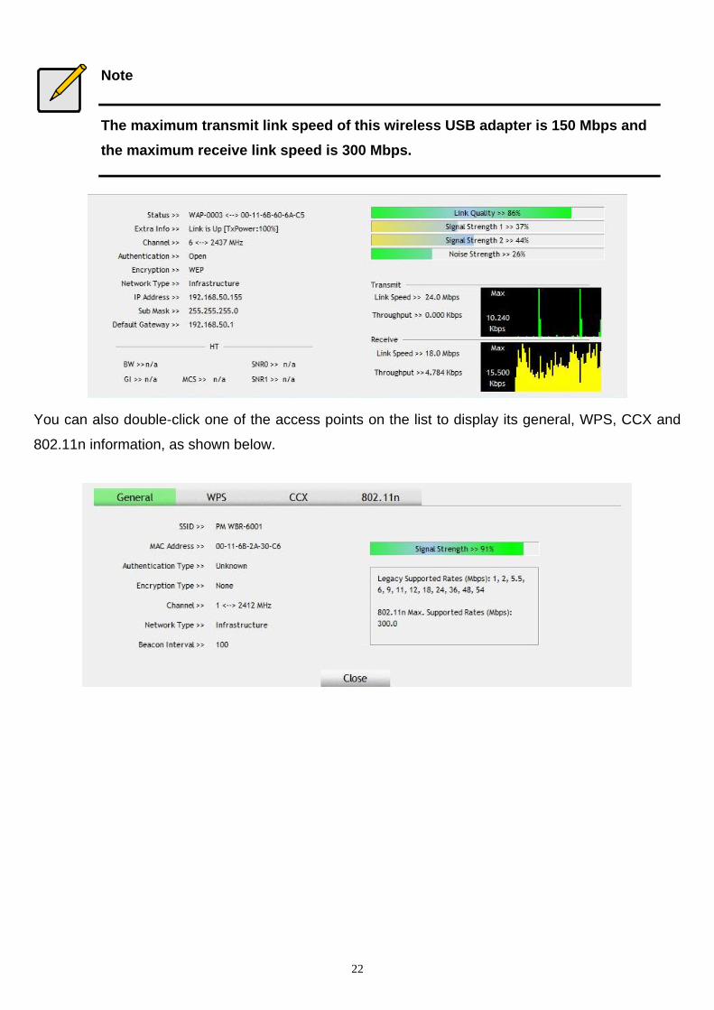
You can press the button on the bottom right corner to display the network status, as shown below.
22
Note
The maximum transmit link speed of this wireless USB adapter is 150 Mbps and
the maximum receive link speed is 300 Mbps.
You can also double-click one of the access points on the list to display its general, WPS, CCX and
802.11n information, as shown below.

23
5.3 Advanced
The Advanced page allows you to configure extended features for the wireless network.
The displayed items on this page can be described as follows:
Wireless Mode: Select 2.4G as the wireless mode.
Enable TX Burst: Enable the option to accelerate the data transmit rate.
Enable TCP Window Size: Adjust TCP window size automatically for better performance.
Fast Roaming: Enable fast roaming at the specified receive power threshold.
Enable CCX (Cisco Compatible Extensions): Enable this option if the network supports Cisco
Compatible Extensions.

24
5.4 Statistics
The statistics page displays the connected-related statistics with detail counter information.
Frames Transmitted Successfully: Frames successfully sent.
Frames Retransmitted Successfully: Successfully retransmitted frames numbers.
Frames Fail To Receive ACK After All Retries: Frames failed transmit after hitting retry limit.
RTS Frames Successfully Receive CTS: Successfully receive CTS after sending RTS frame.
RTS Frames Fail To Receive CTS: Failed to receive CTS after sending RTS.
Reset counters: Reset counters to zero.
Frames Received Successfully: The number of frames successfully received.
Frames Received With CRC Error: The number of frames received with a CRC error.
Frames Dropped Due To Out-of-Resource: The number of frames dropped due to a resource issue.
Duplicate Frames Received: The number of duplicate frames received.
Reset counters: Reset counters to zero.

25
5.5 WMM Wi-Fi Multimedia (WMM), also known as Wireless Multimedia Extensions (WME), is a Wi-Fi Alliance
interoperability certification. It provides basic Quality of Service (QoS) features for IEEE 802.11
wireless networks.
WMM Enable: Enable WMM function.
WMM - Power Save Enable: Enable the power save mode. Please select which ACs you want to
enable.
AC_BK: Background / low priority
AC_BE: Best effort
AC_VI: Video first
AC_VO: Voice first
Direct Link Setup Enable: Enable DLS (Direct Link Setup) function.
MAC Address: Fill in the blanks of Direct Link with MAC Address of STA. The STA must conform to
these two conditions:
1. Connect with an AP that supports DLS features.
2. Ensure that DLS is enabled.
Timeout Value: The Timeout Value indicates the time in seconds before it disconnects automatically.
The value is an integer. The integer must be between 0~65535. A zero value specifies that it stays
connected. The default Timeout Value is 60 seconds.
Apply: The AP that supports DLS features the user filled in will be applied.
Tear Down: Select the device that you want to remove from DLS table and click this button.

26
5.6 WPS Wi-Fi Protected Setup (WPS) is based on push-button or PIN (Personal Identification Number) entry
authentication to provide strong WPA/WPA2 encryption keys to client devices. Users can push a
button on the access point and the client device to exchange the encryption key. With a PIN, users
can enter a code generated by the client device to connect to the network.
WPS Setup - PBC (Push-button Configuration)
1. Push the WPS button on your wireless access point or start WPS standby mode as instructed
by the wireless access point„s user manual.
2. Before you start to establish the wireless connection using WPS, define the Wireless USB
Adapter as a WPS —“Enrollee“ or a —“Registrar“ by selecting the Config Mode options.
Enrollee: An enrollee is the device being added to the network. If the Wireless USB Adapter is set as
an enrollee, click the Rescan button on the utility WPS setup page to search for WPS-enabled access
points near you. All access points found will be displayed in the WPS AP List. Select an access point
on the list and click the Connect button to activate the connection. You can also click the Information
button to see the detailed information about the selected access point.
Registrar: A registrar is the network enrollment center. If the Wireless USB Adapter is set as a
registrar, click the Rescan button on the utility WPS setup page to search for WPS-enabled wireless
devices near you. All enrollees found will be displayed in the WPS Profile List. Select an enrollee on
the list and click the Connect button to activate the connection.
3. Press the physical button on the Wireless USB Adapter or click PBC button on this utility page
to start to establish a wireless connection (this may require several seconds to one minute to
complete)

27
Note
If WPS fails, click the PBC button few more times to try again.
4. When an access point or a WPS enrollee is connected, you can click Disconnect to disconnect
from the connected device, or select another WPS-enabled wireless access point or enrollee,
and then click Connect to establish connection.
5. You can also click the “Rotate” button to select the next access point or enrollee in the list and
establish a connection.
6. To delete an access point from the list, click Delete.
WPS Setup - PIN Configuration
The WPS PIN (Personal Identification Number) setup is optional to the WPS button setup. It is more
secure than using the WPS button. All WPS-compatible devices have their own PIN number.
1. When the Wireless USB Adapter is set as an enrollee, the PIN number of your Wireless USB
Adapter is an eight-digit number located at the upper-right position of configuration utility.
Remember this number and input it to your wireless access point as the WPS PIN code.
Please also refer to the user manual of your wireless access point for instructions about WPS
setup.
2. Click PIN button and wait for few seconds to one minute. If a wireless access point with correct PIN code is found, you will be connected to that access point.
Note
You may have to click PIN for few more times to try again. If you still cannot
connect to an access point this way, please make sure the PIN code you
provided to access point is correct.
3. When the Wireless USB Adapter is set as a registrar, input the enrollee„s PIN number to the
Pin Code box located in the upper-right position of configuration utility.
4. Click PIN button and wait for few seconds to one minute. If a WPS enrollee with correct PIN
code is found, it will be connected to the Wireless USB Adapter.
28
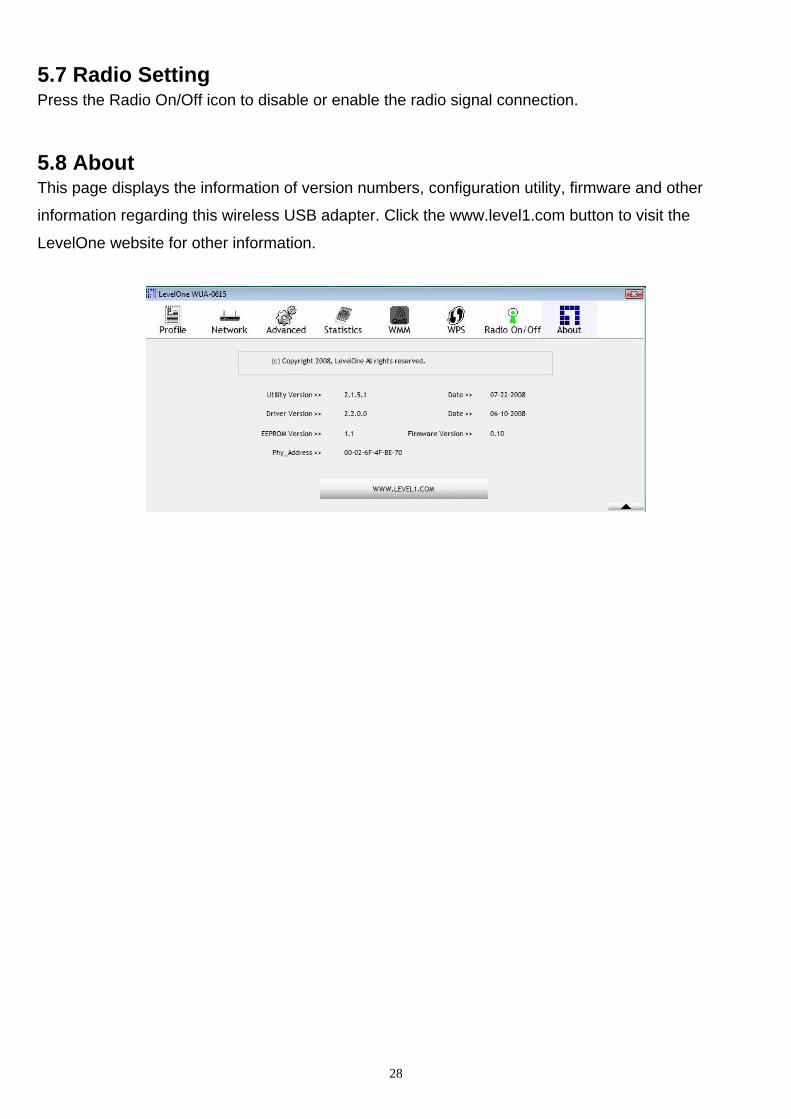
5.7 Radio Setting Press the Radio On/Off icon to disable or enable the radio signal connection.
5.8 About This page displays the information of version numbers, configuration utility, firmware and other
information regarding this wireless USB adapter. Click the www.level1.com button to visit the
LevelOne website for other information.

29
6. Network Planning
LevelOne WUA-0615 N_Max Wireless USB Adapter supports a stand-alone wireless network
configuration, as well as an integrated configuration with Ethernet LANs.
The wireless USB adapter can be configured as:
Ad hoc - for small peer-to-peer networks with other wireless devices
Infrastructure -for a wireless extension to an existing wired LAN through an access point
Network Topologies Ad Hoc Wireless LAN
An ad hoc wireless LAN consists of a group of computers, each equipped with a wireless adapter,
connected via radio signals as an independent wireless LAN.
Computers in a specific ad hoc wireless LAN must be configured to the same radio channel.
An ad hoc wireless LAN can be used for a small branch office or SOHO operation.
Infrastructure Wireless LAN
LevelOne WUA-0615 can also provide access to a wired LAN for wireless workstations. An integrated
wired and wireless LAN is called an Infrastructure configuration. A Basic Service Set (BSS) consists
of a group of wireless PC users, and an access point that is directly connected to the wired LAN.
Each wireless PC in this BSS can communicate with to any computer in its wireless group via a radio
link, or access other computers or network resources in the wired LAN infrastructure via an access
point.

30
The infrastructure configuration not only extends the accessibility of wireless PCs to the wired LAN,
but also increases the effective wireless transmission range for wireless PCs by passing their signal
through one or more access points.
A wireless infrastructure can be used for access to a central database, or for connection
between mobile workers, as shown in the following figure.

31
7. Technical Specifications Technical Specifications
Standard Compliant
IEEE 802.11n Draft 2.0 Specification
IEEE 802.11g
IEEE 802.11b
USB Port Type
USB 2.0/1.1 Connection
Data Transfer Rate
Draft 802.11n: Up to 300Mbps
802.11g: 54 ~ 6 Mbps
802.11b: 11 ~ 1 Mbps
Operating Channels
Ch.1 ~ 11 North America (FCC)
Ch.1 ~ 13 Europe (ETSI)
Operating Frequency
2.412 ~ 2.462GHz North America (FCC)
2.412 ~ 2.472GHz Europe (ETSI)
Transmitter Power (Typical)
Draft 802.11n: 15dBm
802.11g: 14dBm@54 Mbps
15dBm@6 Mbps
802.11b: 18dBm@11 ~ 1 Mbps
Receive Sensitivity (Typical)
Draft 802.11n: -88 dBm MCS 8
-65 dBm MCS 15
802.11g: -90dBm @ 6Mbps
-75dBm @ 54Mbps
802.11b: -91dBm @ 1Mbps
-87dBm @ 11Mbps
Modulation Technique
Draft 802.11n: BPSK, QPSK, 16-QAM, 64-QAM 802.11g: OFDM
802.11b: CCK, QPSK, BPSK
Media Access Protocol
CSMA/CA
Wireless Security
64-bit and 128-bit WEP
WPA-PSK
WPA2-PSK
OS Supported
Windows 2000/XP/Vista
Device Management
Windows Utility Software
Temperature Range
Operating: 0°C to 50°C
Storage: -10°Cto 75°C
Humidity (non-condensing)
5% ~ 95% Typical
Power Requirement
5V±0.25V
Dimensions
83mm x 27mm x 12mm
Certifications
CE, FCC