Embed Size (px)
Citation preview
WU BoyangWU BoyangAPMTAPMT
Communication SatelliteCommunication Satellite
Satcom ABC series (2)Satcom ABC series (2)
Page 2
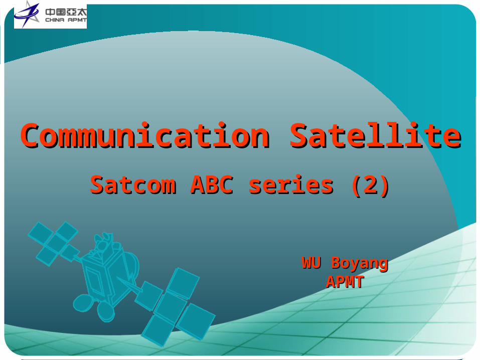
IntroductionIntroduction
PayloadPayloadAntennaAntenna
Transponder (LNA, D/C, IMUX, LCTWTA and OMUX)Transponder (LNA, D/C, IMUX, LCTWTA and OMUX)
BusBusTC&R SubsystemTC&R Subsystem
Electrical Power SubsystemElectrical Power Subsystem
Attitude Control SubsystemAttitude Control Subsystem
Thermal Control SubsystemThermal Control Subsystem
Propulsion SubsystemPropulsion Subsystem
Page 3 3
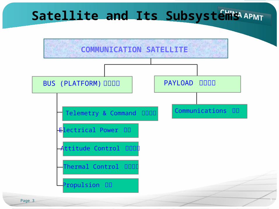
Satellite and Its Subsystems
Telemetry & Command 遥测遥控
Electrical Power 电源
Attitude Control 姿态控制
Thermal Control 温度控制
Propulsion 推进
BUS (PLATFORM) 卫星平台
Communications 通信
PAYLOAD 有效载荷
COMMUNICATION SATELLITE
Page 4
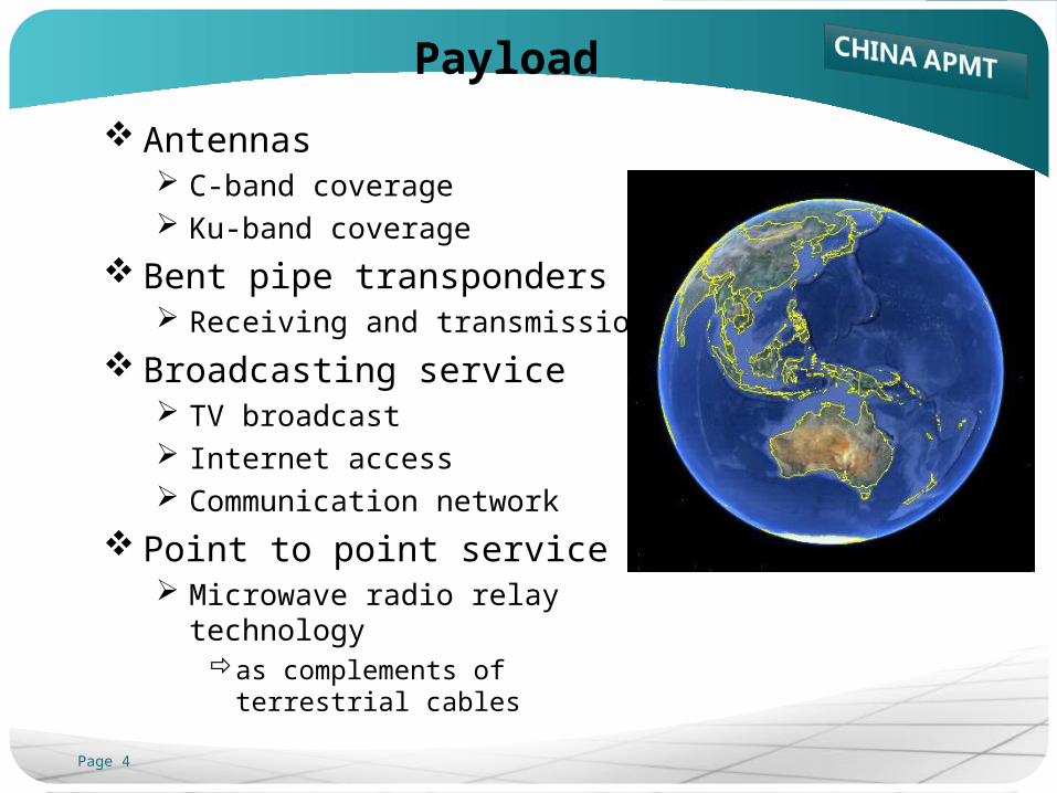
Payload
Antennas C-band coverage Ku-band coverage
Bent pipe transponders Receiving and transmission
Broadcasting service TV broadcast Internet access Communication network
Point to point service Microwave radio relay technology
as complements of terrestrial cables
Page 5
Bus
Platform The infrastructure providing locations for payload
Telemetry and command subsystem Communication with ground control station Supporting tracking and ranging by ground stations
Electrical power subsystem Solar cells converting solar energy into electrical power Batteries maintaining power during solar eclipse
Attitude control subsystem Keeping spacecraft in right orbit Pointing antennas in right direction Pointing solar arrays towards the sun
Page 6
Bus (cont.)
Thermal control subsystem Keeping all spacecraft parts within acceptable temperature
ranges Propulsion subsystem
Bring spacecraft to desired orbit As actuator for station keeping
Page 7
IntroductionIntroduction
PayloadPayloadAntennaAntenna
Transponder (LNA, D/C, IMUX, LCTWTA and OMUX)Transponder (LNA, D/C, IMUX, LCTWTA and OMUX)
BusBusTC&R SubsystemTC&R Subsystem
Electrical Power SubsystemElectrical Power Subsystem
Attitude Control SubsystemAttitude Control Subsystem
Thermal Control SubsystemThermal Control Subsystem
Propulsion SubsystemPropulsion Subsystem
Page 8
Antennas Onboard
Reflector Antennas Simplest and most effective for FSS and BSS satellite
Deployable reflector 2 to 3 meters in diameter Mounted on east and/or west side of S/C body Stowed when launch and deployed in-orbit Fine-tuning footprint pointing
Steerable antenna 1 to 1.5 meters in diameter Mounted on earth deck of S/C body Installed with wider moving range
antenna pointing could be changed in limited directions
Page 9
Gain and Coverage
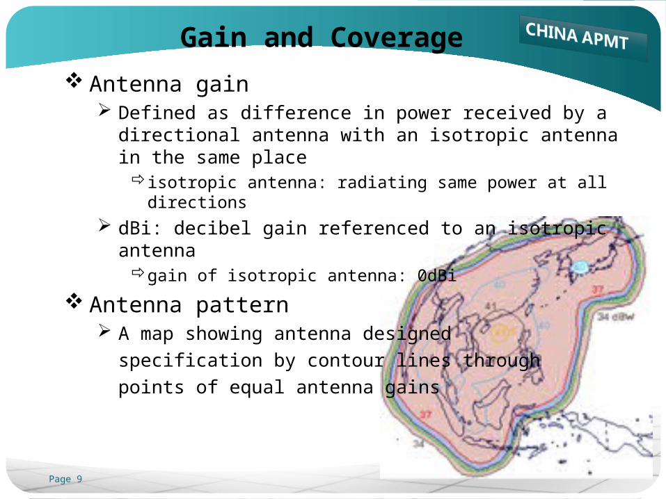
Antenna gain Defined as difference in power received by a directional
antenna with an isotropic antenna in the same place isotropic antenna: radiating same power at all directions
dBi: decibel gain referenced to an isotropic antenna gain of isotropic antenna: 0dBi
Antenna pattern A map showing antenna designed
specification by contour lines through
points of equal antenna gains
Page 10
Gain and Coverage (cont.)
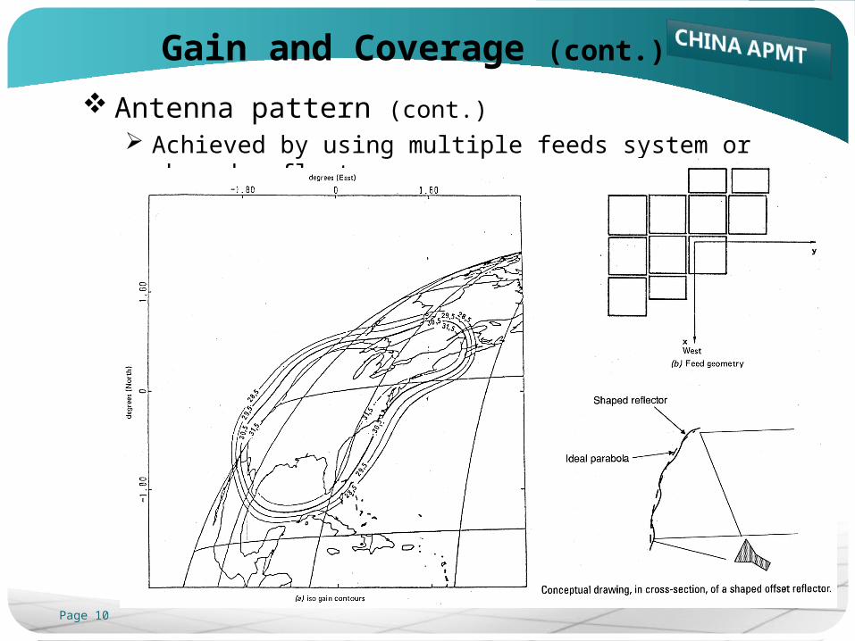
Antenna pattern (cont.) Achieved by using multiple feeds system or shaped reflector
Page 11
Introduction Introduction
PayloadPayloadAntennaAntenna
Transponder (LNA, D/C, IMUX, LCTWTA and OMUX)Transponder (LNA, D/C, IMUX, LCTWTA and OMUX)
BusBusTC&R SubsystemTC&R Subsystem
Electrical Power SubsystemElectrical Power Subsystem
Attitude Control SubsystemAttitude Control Subsystem
Thermal Control SubsystemThermal Control Subsystem
Propulsion SubsystemPropulsion Subsystem
Page 12
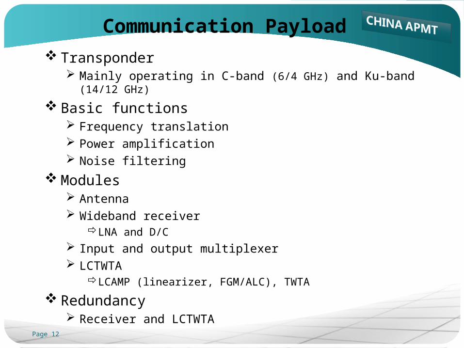
Communication Payload
Transponder Mainly operating in C-band (6/4 GHz) and Ku-band (14/12 GHz)
Basic functions Frequency translation Power amplification Noise filtering
Modules Antenna Wideband receiver
LNA and D/C
Input and output multiplexer LCTWTA
LCAMP (linearizer, FGM/ALC), TWTA
Redundancy Receiver and LCTWTA
Page 13
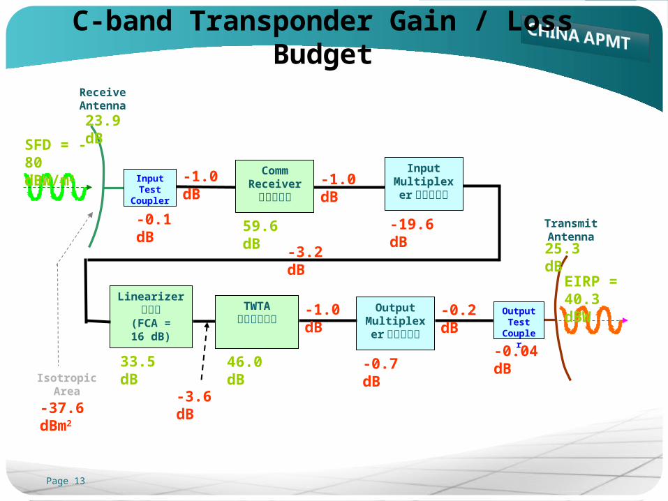
Receive Antenna
-0.04 dB
23.9 dB
Comm Receiver
通信接收机
59.6 dB Transmit Antenna
33.5 dB 46.0 dB -0.7 dB
25.3 dB
Input Test
Coupler
-0.1 dB
Input Multiplexer输入复接器
Linearizer线性器
(FCA = 16 dB)
TWTA行波管放大器
Output Multiplexer输出复接器
Output Test
Coupler
-1.0 dB -1.0 dB
-3.2 dB
-3.6 dB
-1.0 dB -0.2 dB
-19.6 dB
SFD = - 80 dBW/m2
Isotropic Area
-37.6 dBm2
EIRP = 40.3 dBW
C-band Transponder Gain / Loss Budget
Page 14
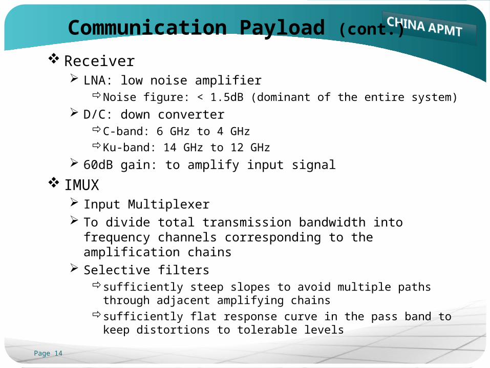
Communication Payload (cont.)
Receiver LNA: low noise amplifier
Noise figure: < 1.5dB (dominant of the entire system)
D/C: down converter C-band: 6 GHz to 4 GHz Ku-band: 14 GHz to 12 GHz
60dB gain: to amplify input signal
IMUX Input Multiplexer To divide total transmission bandwidth into frequency
channels corresponding to the amplification chains Selective filters
sufficiently steep slopes to avoid multiple paths through adjacent amplifying chains
sufficiently flat response curve in the pass band to keep distortions to tolerable levels
Page 15
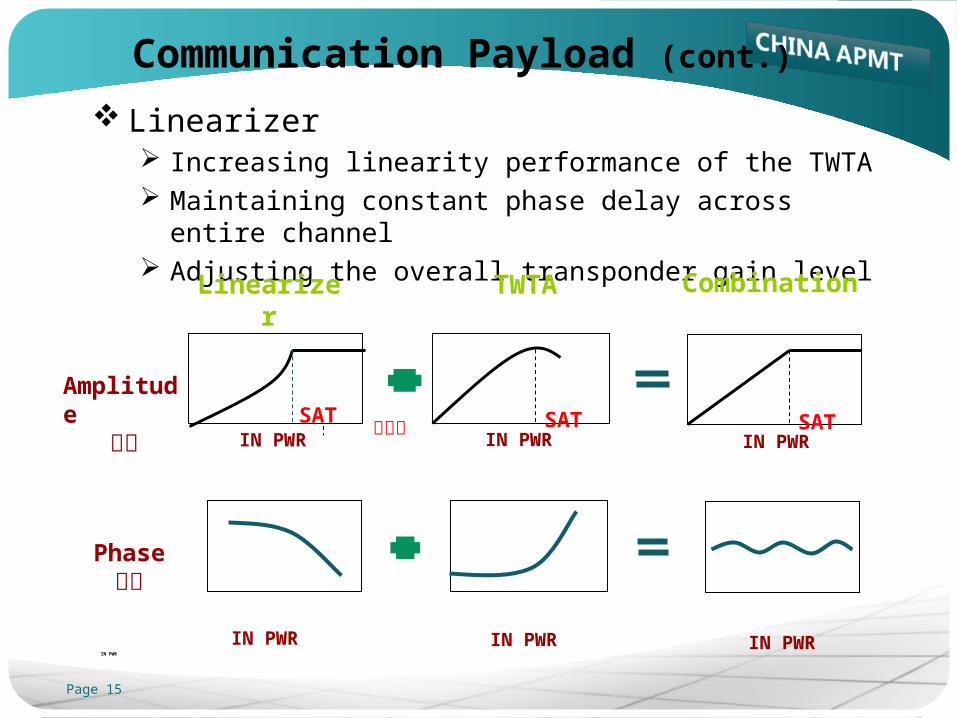
Communication Payload (cont.)
Linearizer Increasing linearity performance of the TWTA Maintaining constant phase delay across entire channel Adjusting the overall transponder gain level
IN PWR
IN PWR IN PWRIN PWR
Phase相位
TWTALinearizer Combination
Amplitude幅度 SAT
IN PWRSAT
IN PWRSAT
IN PWR饱和点
Page 16
Communication Payload (cont.)
TWTA Traveling wave tube amplifier Non-linear active device Typical gain of 50 to 60 dB
higher downlink power, higher C/N, higher receive quality
OMUX Output Multiplexer TWTA outputs combined together, then into transmit antenna Reject the out-of-band harmonics and spurious noises
Page 17
Receive Antenna
-0.04 dB
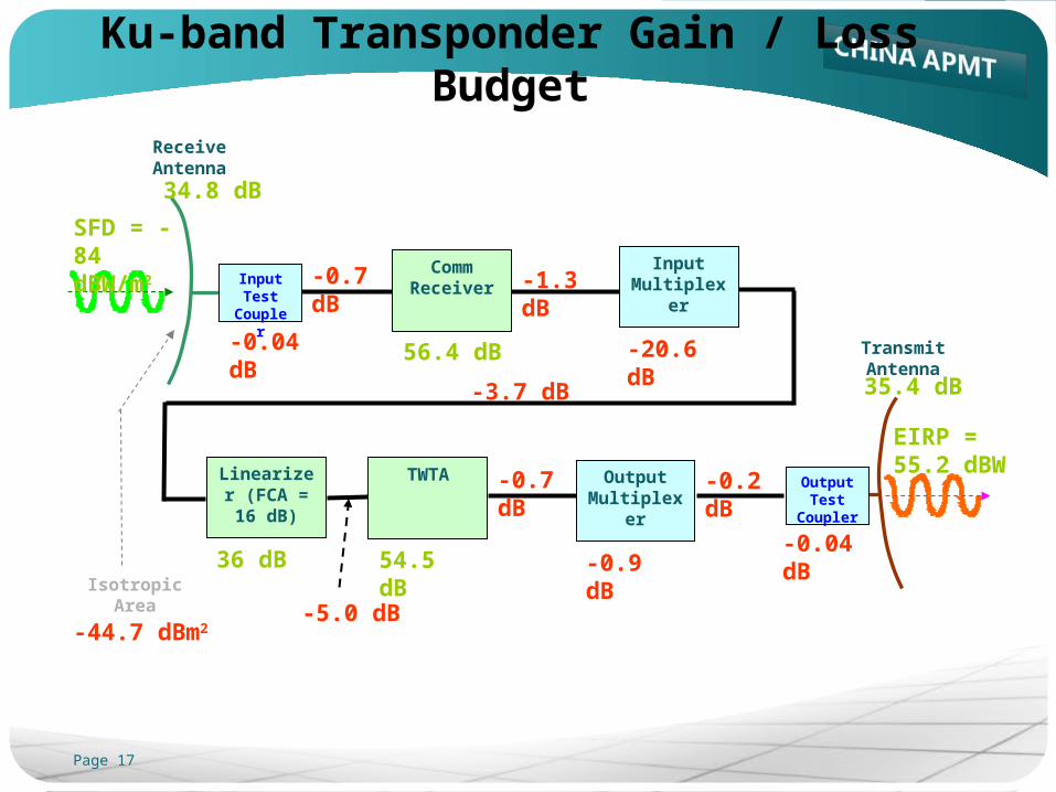
34.8 dB
Comm Receiver
56.4 dB Transmit Antenna
36 dB 54.5 dB -0.9 dB
35.4 dB
Input Test
Coupler
-0.04 dB
Input Multiplexer
Linearizer (FCA = 16
dB)
TWTA Output Multiplexer
Output Test
Coupler
-0.7 dB -1.3 dB
-3.7 dB
-5.0 dB
-0.7 dB -0.2 dB
-20.6 dB
SFD = - 84 dBW/m2
Isotropic Area
-44.7 dBm2
EIRP = 55.2 dBW
Ku-band Transponder Gain / Loss Budget
Page 18
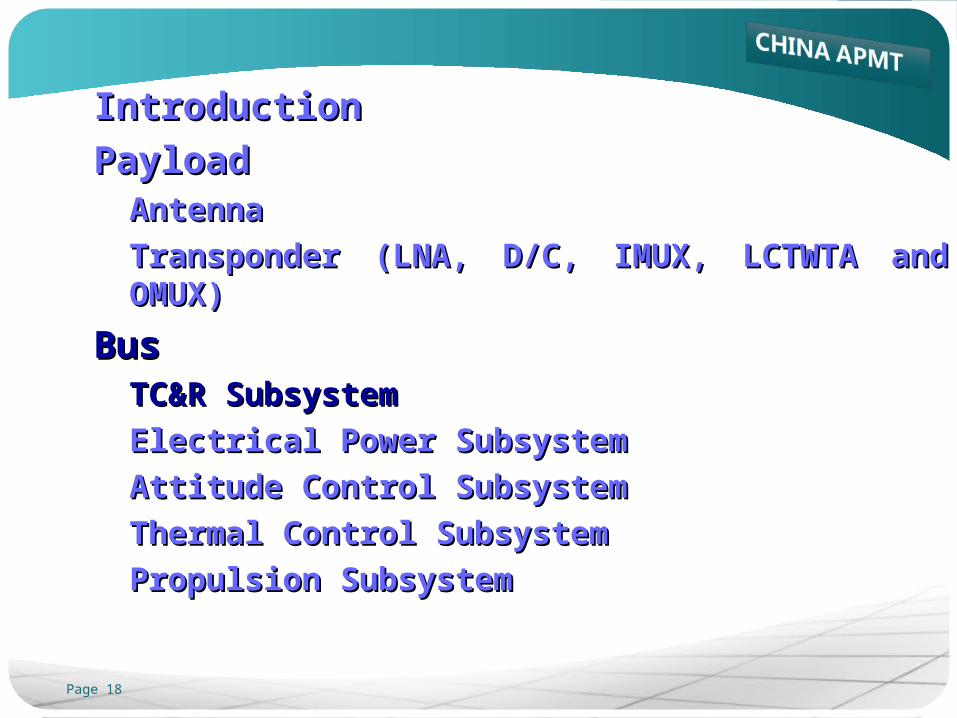
IntroductionIntroduction
PayloadPayloadAntennaAntenna
Transponder (LNA, D/C, IMUX, LCTWTA and OMUX)Transponder (LNA, D/C, IMUX, LCTWTA and OMUX)
BusBusTC&R SubsystemTC&R Subsystem
Electrical Power SubsystemElectrical Power Subsystem
Attitude Control SubsystemAttitude Control Subsystem
Thermal Control SubsystemThermal Control Subsystem
Propulsion SubsystemPropulsion Subsystem
Page 19
Telemetry, Command and Ranging
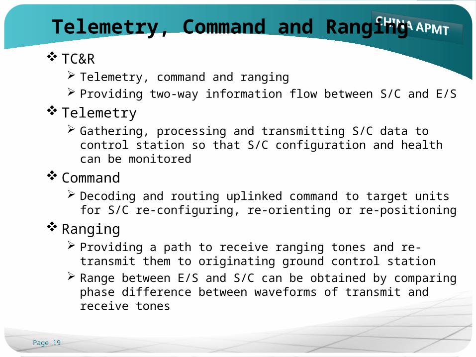
TC&R Telemetry, command and ranging Providing two-way information flow between S/C and E/S
Telemetry Gathering, processing and transmitting S/C data to control
station so that S/C configuration and health can be monitored
Command Decoding and routing uplinked command to target units for S/C
re-configuring, re-orienting or re-positioning
Ranging Providing a path to receive ranging tones and re-transmit them
to originating ground control station Range between E/S and S/C can be obtained by comparing
phase difference between waveforms of transmit and receive tones
Page 20
Telemetry
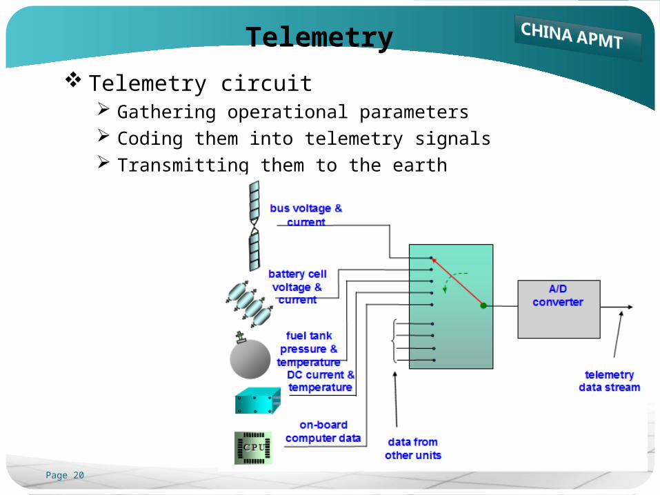
Telemetry circuit Gathering operational parameters Coding them into telemetry signals Transmitting them to the earth
Page 21
Command
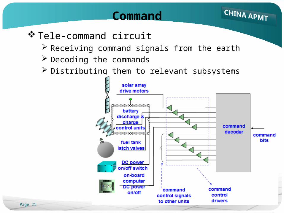
Tele-command circuit Receiving command signals from the earth Decoding the commands Distributing them to relevant subsystems
Page 22
Ranging
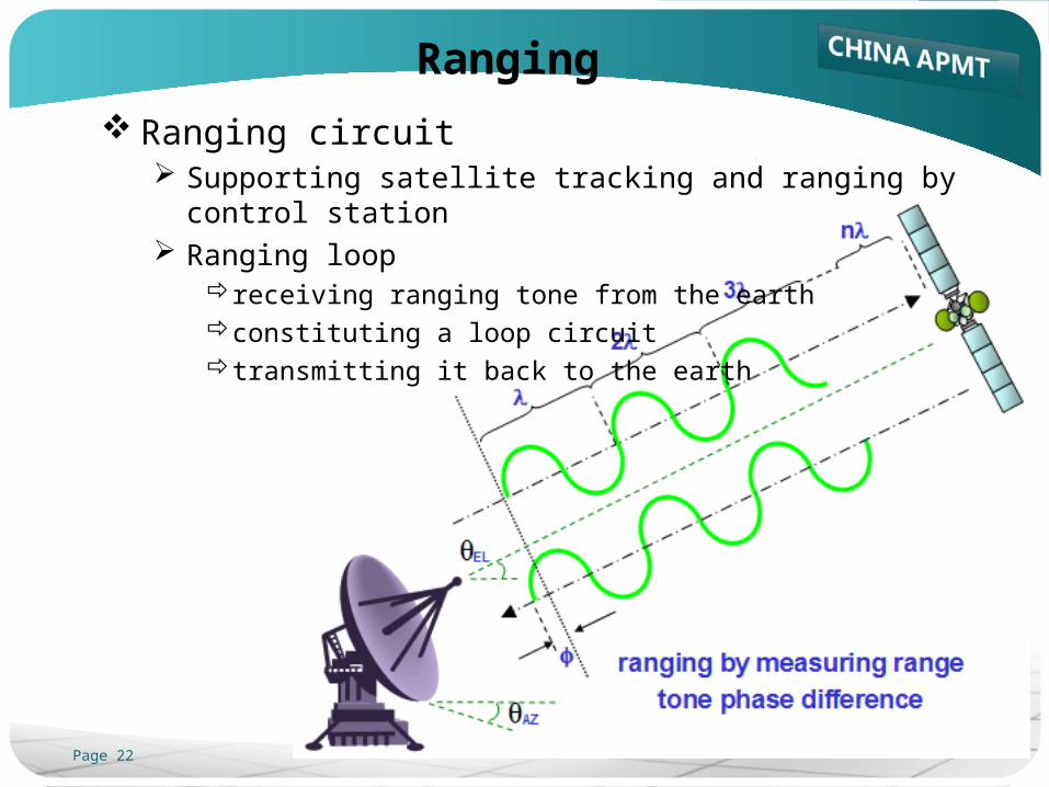
Ranging circuit Supporting satellite tracking and ranging by control station Ranging loop
receiving ranging tone from the earthconstituting a loop circuittransmitting it back to the earth
Page 23
IntroductionIntroduction
PayloadPayloadAntennaAntenna
Transponder (LNA, D/C, IMUX, LCTWTA and OMUX)Transponder (LNA, D/C, IMUX, LCTWTA and OMUX)
BusBusTC&R SubsystemTC&R Subsystem
Electrical Power SubsystemElectrical Power Subsystem
Attitude Control SubsystemAttitude Control Subsystem
Thermal Control SubsystemThermal Control Subsystem
Propulsion SubsystemPropulsion Subsystem
Page 24
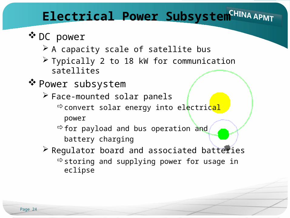
Electrical Power Subsystem
DC power A capacity scale of satellite bus Typically 2 to 18 kW for communication satellites
Power subsystem Face-mounted solar panels
convert solar energy into electrical
power for payload and bus operation and
battery charging
Regulator board and associated batteries storing and supplying power for usage in eclipse
Page 25
Solar Arrays and Batteries
Solar arrays 2 deployable solar wings Each wing consists of 3 to 5 panels Silicon solar cells: transfer solar energy to electricity Each panel is covered with solar cells (silicon or gallium
arsenide) connected in series and in parallel Aligned with the earth’s N-S axis Each wing is made to face the sun by an electric step motor
which turns at 1rev./24hrs
Rechargeable batteries Power supply before solar wings deployed Power supply in eclipse
charging at low rate with the sunlightdischarging to provide electrical power during eclipse period
Page 26
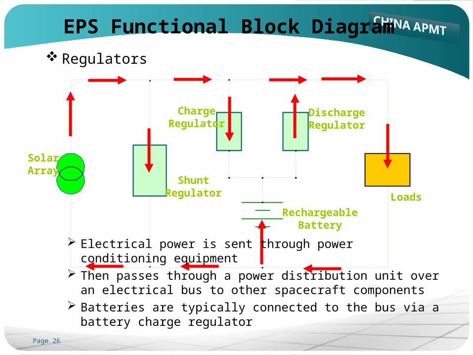
Loads
ShuntRegulator
ChargeRegulator
DischargeRegulator
RechargeableBattery
Solar Array
EPS Functional Block Diagram
Regulators
Electrical power is sent through power conditioning equipment Then passes through a power distribution unit over an electrical
bus to other spacecraft components Batteries are typically connected to the bus via a battery
charge regulator
Page 27
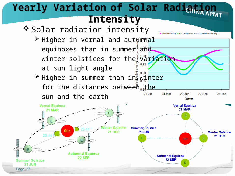
Yearly Variation of Solar Radiation Intensity
Solar radiation intensity Higher in vernal and autumnal
equinoxes than in summer and
winter solstices for the variation
at sun light angle Higher in summer than in winter
for the distances between the
sun and the earth
Page 28
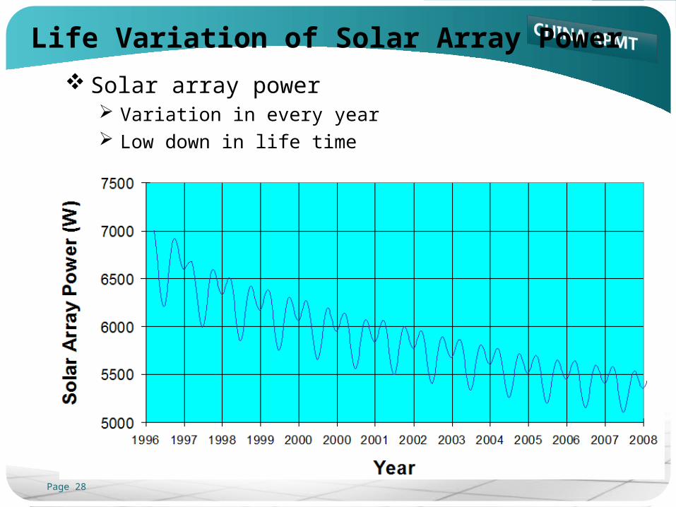
Life Variation of Solar Array Power
Solar array power Variation in every year Low down in life time

Page 29
IntroductionIntroduction
PayloadPayloadAntennaAntenna
Transponder (LNA, D/C, IMUX, LCTWTA and OMUX)Transponder (LNA, D/C, IMUX, LCTWTA and OMUX)
BusBusTC&R SubsystemTC&R Subsystem
Electrical Power SubsystemElectrical Power Subsystem
Attitude Control SubsystemAttitude Control Subsystem
Thermal Control SubsystemThermal Control Subsystem
Propulsion SubsystemPropulsion Subsystem
Page 30
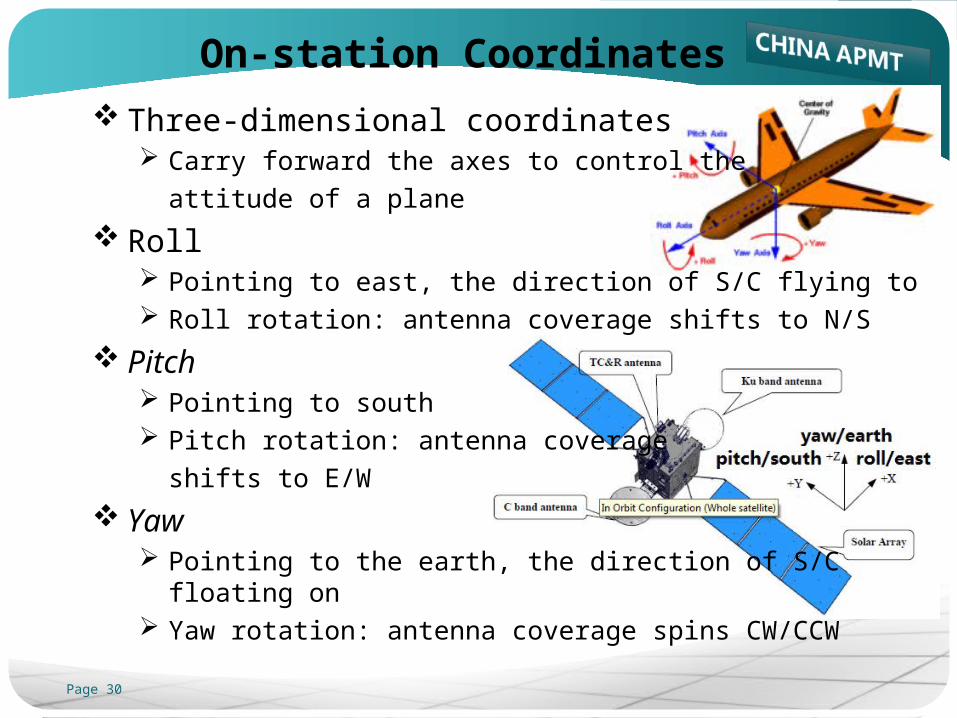
On-station Coordinates
Three-dimensional coordinates Carry forward the axes to control the
attitude of a plane
Roll Pointing to east, the direction of S/C flying to Roll rotation: antenna coverage shifts to N/S
Pitch Pointing to south Pitch rotation: antenna coverage
shifts to E/W
Yaw Pointing to the earth, the direction of S/C floating on Yaw rotation: antenna coverage spins CW/CCW
Page 31
Attitude Control and Station Keeping
Attitude and orbit control subsystem Sensors: to measure vehicle orientation Flight software: to offer control algorithm Actuators: to re-orient the S/C, and keep orbital position
Attitude control Automatically executed by ACS Earth-pointing: keeping antennas in the right directions Sun pointing: positioning solar arrays towards the sun
Station keeping Manually ordered by TT&C station To counteract the movement of a satellite witch be affected
by the gravitational field of the sun, the moon, and the earth The amount of movement can be predicted using some
complicated mathematical equations
Page 32
Equipments of ACS
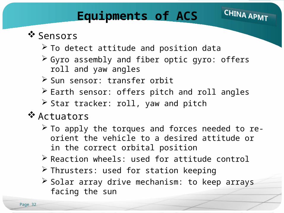
Sensors To detect attitude and position data Gyro assembly and fiber optic gyro: offers roll and yaw angles Sun sensor: transfer orbit Earth sensor: offers pitch and roll angles Star tracker: roll, yaw and pitch
Actuators To apply the torques and forces needed to re-orient the
vehicle to a desired attitude or in the correct orbital position Reaction wheels: used for attitude control Thrusters: used for station keeping Solar array drive mechanism: to keep arrays facing the sun
Page 33
Equipments of ACS (cont.)
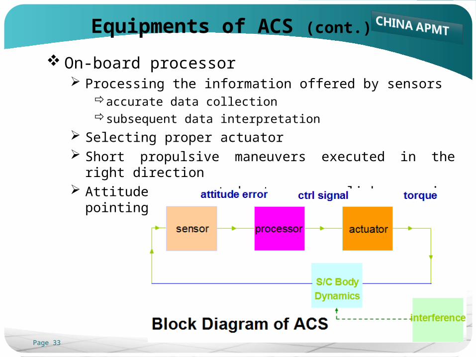
On-board processor Processing the information offered by sensors
accurate data collection subsequent data interpretation
Selecting proper actuator Short propulsive maneuvers executed in the right direction Attitude corrected to accomplish precise pointing
Page 34
IntroductionIntroduction
PayloadPayloadAntennaAntenna
Transponder (LNA, D/C, IMUX, LCTWTA and OMUX)Transponder (LNA, D/C, IMUX, LCTWTA and OMUX)
BusBusTC&R SubsystemTC&R Subsystem
Electrical Power SubsystemElectrical Power Subsystem
Attitude Control SubsystemAttitude Control Subsystem
Thermal Control SubsystemThermal Control Subsystem
Propulsion SubsystemPropulsion Subsystem
Page 35
Thermal Environment
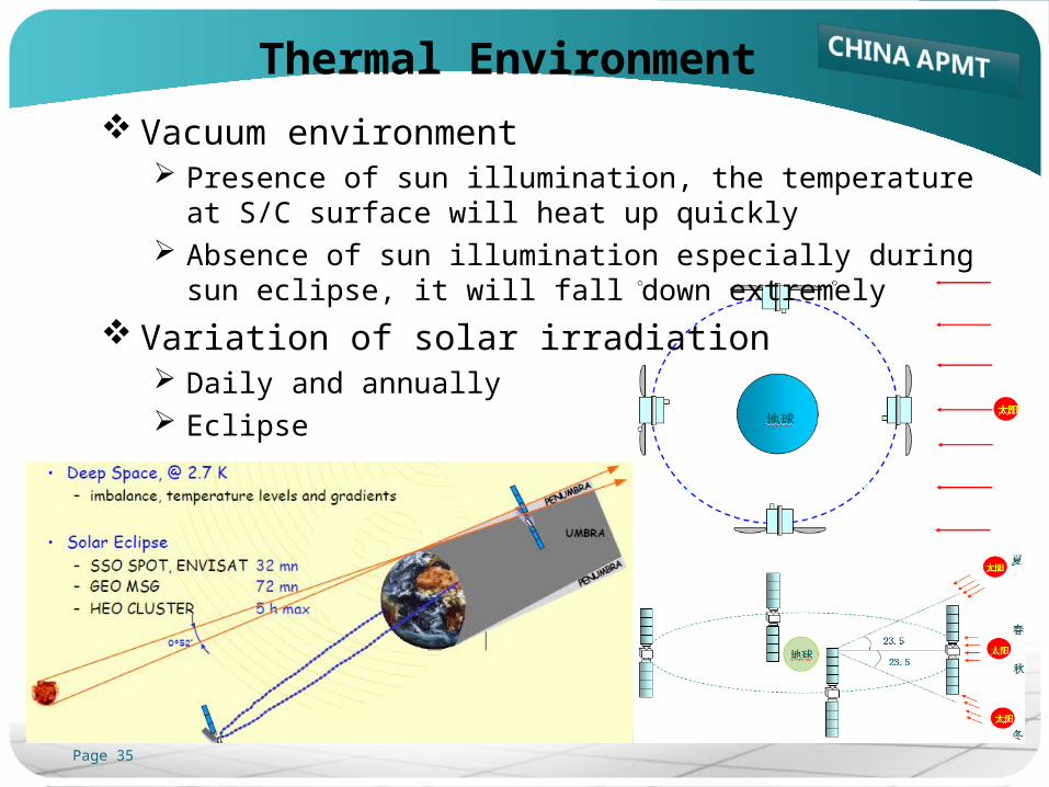
Vacuum environment Presence of sun illumination, the temperature at S/C surface
will heat up quickly Absence of sun illumination especially during sun eclipse, it
will fall down extremely
Variation of solar irradiation Daily and annually Eclipse
Page 36
Why Thermal Control
Thermal control Can be composed both of passive and active items Protecting the equipment from too hot temperatures
by thermal insulation from external heat fluxesor by proper heat removal from internal sources
Protecting the equipment from too cold temperaturesby thermal insulation from external sinksby enhanced heat absorption from external sourcesor by heat release from internal sources
Referencehttp://www.tak2000.com/data/Satellite_TC.pdf
Page 37
How Thermal Control
Methods Reflection
optical solar reflector, thermal control coating
Insulationmulti-layer insulation for external surface
Radiation radiators on external N/S side to reject heat to space
Heatingheaters for propellant lines, thrusters, main engine, and other
equipments from too cold environment
Conductionheat pipe spreading out heat generated by HPA and other
internal active parts
Page 38
Passive Thermal Control
MLI Multi-layer Insulation Protecting spacecraft from excessive heating and cooling
OSR Optical Solar Reflectors Improving heat rejection capability of the external radiators Reducing absorption of external solar flux
Coating Changing thermo-optical properties of external surfaces
Thermal fillers Improving thermal coupling at selected interfaces
Thermal doublers Spreading heat dissipation under unit and on the radiator
surface
Page 39
Active Thermal Control
Thermostatically controlled resistive electric heaters Keeping equipment temperature above its lower limit during
the mission cold phases
Fluid loops Transferring the heat dissipated by equipment to the radiators Single-phase loop, controlled by a pump Two-phase loops, composed of heat pipes (HP), loop heat
pipes (LHP) or capillary pumped loops (CPL)
Thermoelectric coolers Louvers
Changing heat rejection capability as a function of temperature
Page 40
IntroductionIntroduction
PayloadPayloadAntennaAntenna
Transponder (LNA, D/C, IMUX, LCTWTA and OMUX)Transponder (LNA, D/C, IMUX, LCTWTA and OMUX)
BusBusTC&R SubsystemTC&R Subsystem
Electrical Power SubsystemElectrical Power Subsystem
Attitude Control SubsystemAttitude Control Subsystem
Thermal Control SubsystemThermal Control Subsystem
Propulsion SubsystemPropulsion Subsystem
Page 41
Propulsion Subsystem
Conventional propulsion subsystem Fuel and tanks
launch mass: S/C weight at the beginning of lifedry mass: S/C weight at the end of life
Pipes and valves Thrusters
keeping spacecraft in its assigned place in orbitunloading momentum wheels
Main engine bringing the spacecraft to its permanent position
Thermal control Monitoring component temperatures of propulsion subsystem Preheating tanks and thrusters in preparation for a spacecraft
maneuver
Page 42
Function
Generating thrust and providing impulse Firing at transfer orbit to achieve GEO orbit
Providing impulse, maintaining S/C attitude and orbital position During GEO operations
Providing minimum impulse bits During normal mode operation For momentum wheel unloading
Providing velocity change and attitude control During station keeping maneuvers
Page 43
Functional Parts
Pressure supply and regulation Helium tanks
providing helium gas as pressurant
Pressure regulationpressurizing and regulating, valve checking and latching, helium
filtering
Propellant storage and distribution Propellant storage
propellant tanks and management devices
Propellant distributionpipes to LAE and thrusters
Thrusters and main engine LAE
liquid apogee engine
16 thrustersfor attitude and orbit control
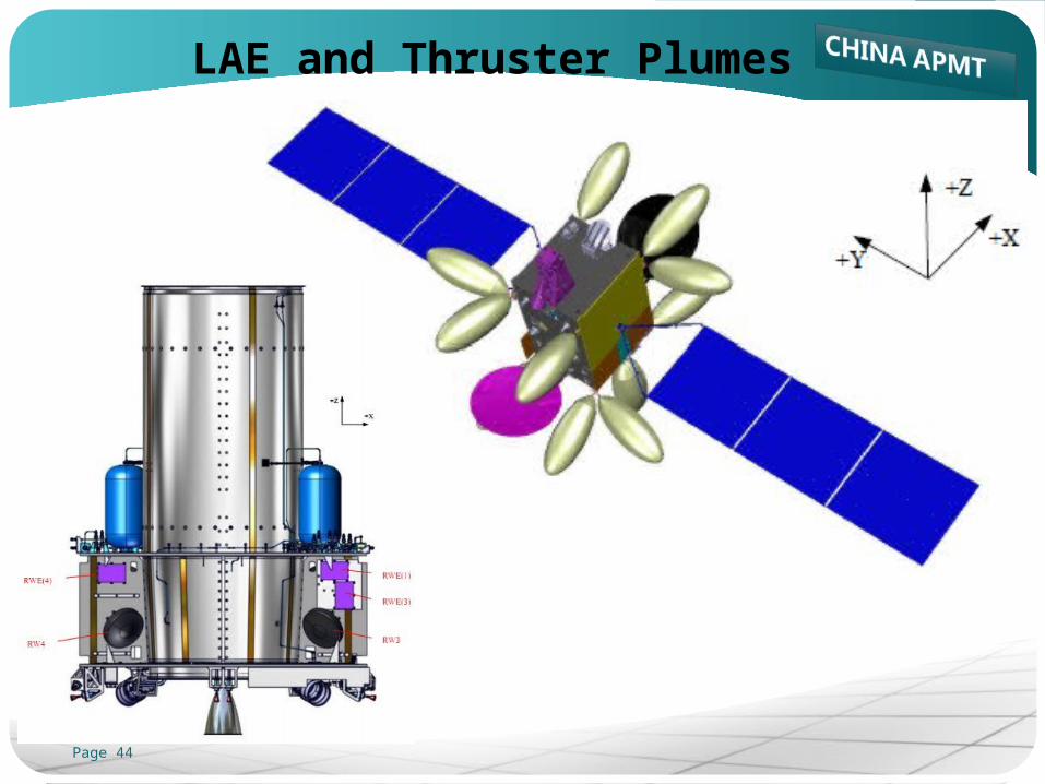
Page 44
LAE and Thruster Plumes
Page 45
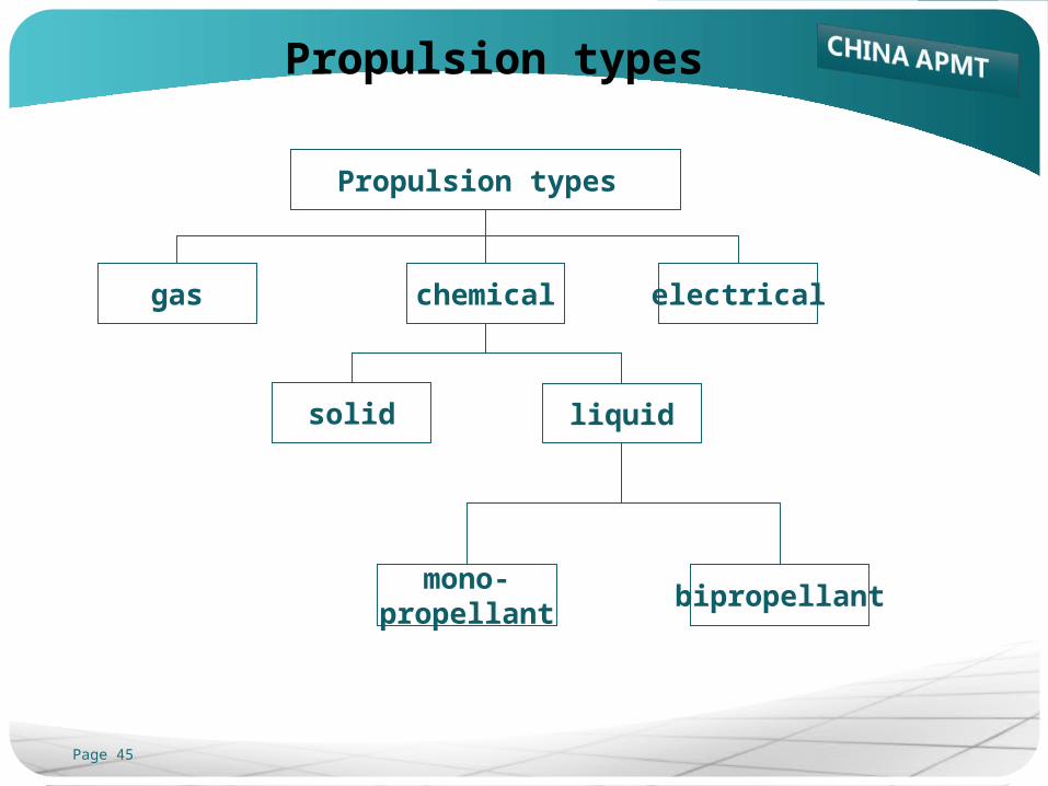
Propulsion types
gas chemical electrical
solid liquid
mono-propellant
bipropellant
Propulsion types

Page 46
Reference: AsiaSat: Customer Training Materials, April 2004Wikipedia
Thanks!Thanks!
Welcome to my homepageWelcome to my homepage
www.satcomengr.comwww.satcomengr.com
![Jaba Satcom S.A. de C.V. - Telefonos Satelitales · Jaba Satcom S.A. de C.V. [ Ingeniería SatCom ] [ RF Technology ] [ Interoperability ] [ AeroSpace] [Comunicaciones ] [ Telefonía](https://img.pdfslide.us/doc/110x75/5e86aa1b58f7f502e224fe33/jaba-satcom-sa-de-cv-telefonos-satelitales-jaba-satcom-sa-de-cv-ingeniera.jpg)

![Jaba Satcom S.A. de C.V. - [ VoIP Satelital ] Telefonia … Satcom S.A. de C.V. [ Ingeniería SatCom ] [ RF Technology ] [ Interoperability ] [ AeroSpace] [Comunicaciones ] [ Telefonía](https://img.pdfslide.us/doc/110x75/5ae2fc697f8b9a7b218c85c1/jaba-satcom-sa-de-cv-voip-satelital-telefonia-satcom-sa-de-cv.jpg)


![Satcom Overview[1]](https://img.pdfslide.us/doc/110x75/577d23ae1a28ab4e1e9a7a50/satcom-overview1.jpg)