Embed Size (px)
Citation preview
WSAT-XEE 82-102-122-162- 182-222-262-302
AIR COOLED WATER CHILLER FOR OUTDOOR INSTALLATION
Installation and Use Manual
M0G140F7-01 06/11/07

U N I T I D E N T I F I C A T I O N . . . . . . . . . . . . . . . . . . . . . . . . . . . . . . . . . . . . . . . . . . . . . . . . . . . . . . . . . . . . . . . . . . . . . . . . . . . 4 I N S T R U C T I O N S F O R T H E U S E R . . . . . . . . . . . . . . . . . . . . . . . . . . . . . . . . . . . . . . . . . . . . . . . . . . . . . . . . . . . . . . . 5
COMMON CAUSES OF SHUTDOWN ...........................................................................................................................5 G E N E R A L W A R N I N G S . . . . . . . . . . . . . . . . . . . . . . . . . . . . . . . . . . . . . . . . . . . . . . . . . . . . . . . . . . . . . . . . . . . . . . . . . . . . 8 R E S I D U A L R I S K S . . . . . . . . . . . . . . . . . . . . . . . . . . . . . . . . . . . . . . . . . . . . . . . . . . . . . . . . . . . . . . . . . . . . . . . . . . . . . . . . . 9 R E C E P T I O N . . . . . . . . . . . . . . . . . . . . . . . . . . . . . . . . . . . . . . . . . . . . . . . . . . . . . . . . . . . . . . . . . . . . . . . . . . . . . . . . . . . . . . . . 1 2
INSPECTION UPON RECEPTION...............................................................................................................................12 STORAGE ....................................................................................................................................................................12 HANDLING ...................................................................................................................................................................12
P O S I T I O N I N G . . . . . . . . . . . . . . . . . . . . . . . . . . . . . . . . . . . . . . . . . . . . . . . . . . . . . . . . . . . . . . . . . . . . . . . . . . . . . . . . . . . . . 1 3 GENERAL.....................................................................................................................................................................13 FUNCTIONAL CLEARANCES......................................................................................................................................13 POSITIONING ..............................................................................................................................................................13
W A T E R C O N N E C T I O N S . . . . . . . . . . . . . . . . . . . . . . . . . . . . . . . . . . . . . . . . . . . . . . . . . . . . . . . . . . . . . . . . . . . . . . . . . 1 5 GENERAL.....................................................................................................................................................................15 EXCHANGER USE SIDE .............................................................................................................................................15 DIAGRAM OF RECOMMENDED USE SIDE CONNECTION.......................................................................................16 RECOVERY EXCHANGER ..........................................................................................................................................16
E L E C T R I C A L C O N N E C T I O N . . . . . . . . . . . . . . . . . . . . . . . . . . . . . . . . . . . . . . . . . . . . . . . . . . . . . . . . . . . . . . . . . . . 1 7 GENERAL.....................................................................................................................................................................17 STANDARD UNIT ELECTRICAL DATA .......................................................................................................................17 CONNECTION TO THE MAINS ...................................................................................................................................17 FUNCTIONAL CONNECTIONS....................................................................................................................................18 SYSTEM COMPOSITION.............................................................................................................................................19
S T A R T - U P . . . . . . . . . . . . . . . . . . . . . . . . . . . . . . . . . . . . . . . . . . . . . . . . . . . . . . . . . . . . . . . . . . . . . . . . . . . . . . . . . . . . . . . . . . 2 1 PRELIMINARY CHECKS..............................................................................................................................................21 REFRIGERANT SYSTEM ............................................................................................................................................21 WATER SYSTEM .........................................................................................................................................................21 ELECTRICAL SYSTEM ................................................................................................................................................21 VERIFy tensions – absorptions.....................................................................................................................................21 UNIT EQUIPPED WITH SCROLL COMPRESSORS ...................................................................................................22 REMOTE INPUT CONFIGURATIONS .........................................................................................................................22 SETTING THE SET-POINT ..........................................................................................................................................22 EVAPORATOR WATER FLOW RATE .........................................................................................................................22 REFRIGERANT CIRCUIT PARAMETER CHECK........................................................................................................22
C O N T R O L . . . . . . . . . . . . . . . . . . . . . . . . . . . . . . . . . . . . . . . . . . . . . . . . . . . . . . . . . . . . . . . . . . . . . . . . . . . . . . . . . . . . . . . . . . 2 3 OPERING MODES .......................................................................................................................................................23 CHARACTERISTICS ....................................................................................................................................................23 SET POINT...................................................................................................................................................................24 KEYPAD .......................................................................................................................................................................25
R O U T I N E M A I N T E N A N C E . . . . . . . . . . . . . . . . . . . . . . . . . . . . . . . . . . . . . . . . . . . . . . . . . . . . . . . . . . . . . . . . . . . . . . . 2 9 MAINTENANCE INSPECTIONS...................................................................................................................................30 97/23 CE PED directive ................................................................................................................................................30 PUT AT REST...............................................................................................................................................................30 REFRIGERANT TABLES .............................................................................................................................................31
T R O U B L E S H O O T I N G . . . . . . . . . . . . . . . . . . . . . . . . . . . . . . . . . . . . . . . . . . . . . . . . . . . . . . . . . . . . . . . . . . . . . . . . . . . . 3 3 D E C O M M I S S I O N I N G O F T H E U N I T . . . . . . . . . . . . . . . . . . . . . . . . . . . . . . . . . . . . . . . . . . . . . . . . . . . . . . . . . . . 3 6
DISCONNECTING THE UNIT ......................................................................................................................................36 DISMANTLING AND DISPOSAL..................................................................................................................................36
T E C H N I C A L D A T A . . . . . . . . . . . . . . . . . . . . . . . . . . . . . . . . . . . . . . . . . . . . . . . . . . . . . . . . . . . . . . . . . . . . . . . . . . . . . . . . 3 7 D I M E N S I O N S . . . . . . . . . . . . . . . . . . . . . . . . . . . . . . . . . . . . . . . . . . . . . . . . . . . . . . . . . . . . . . . . . . . . . . . . . . . . . . . . . . . . . . 3 9
M0G140F7-01 06/11/07 pag 4
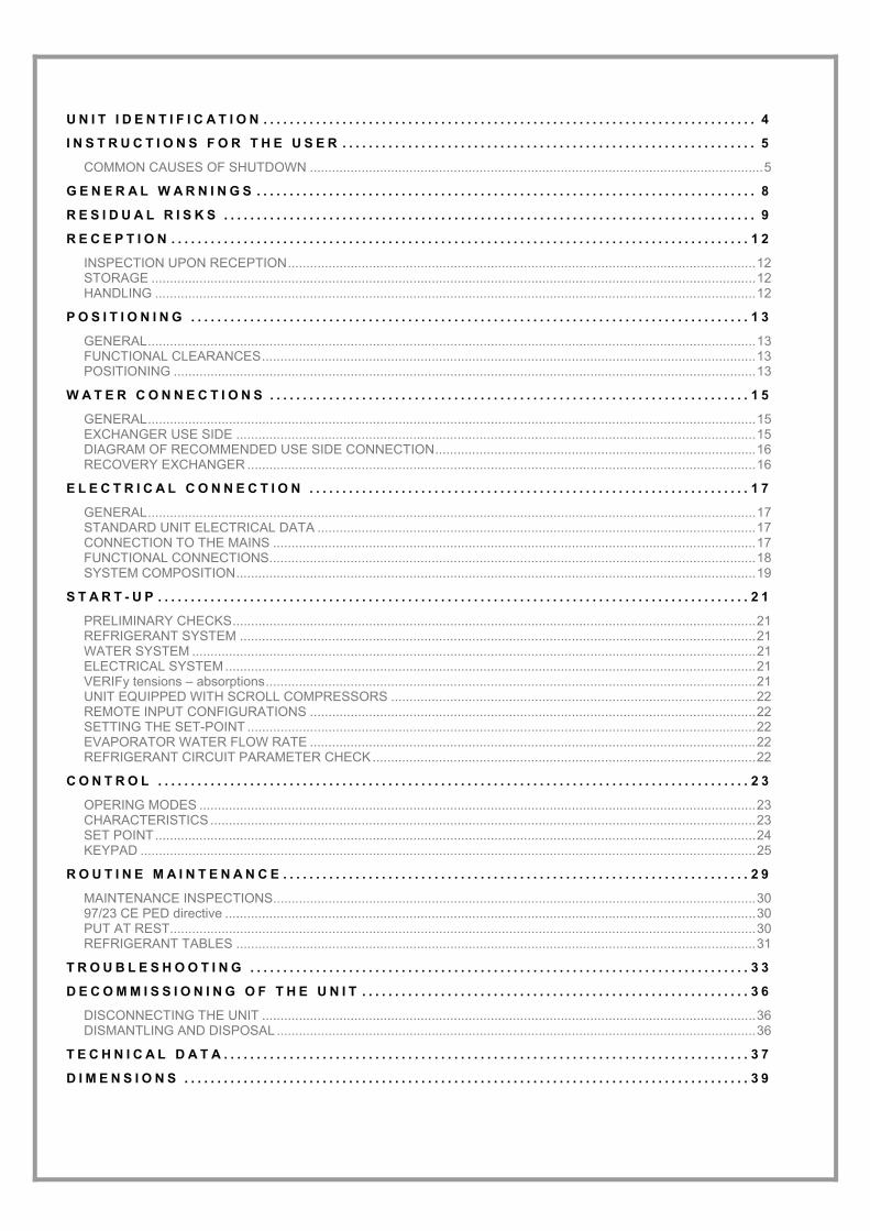
UNIT IDENTIFICATION SERIAL NUMBER LABEL
The units are identified by the serial number label shown here.
The label lists the type of unit (series and size), serial number, year of manufacture, number of electrical diagram, main technical data, logo and address of the manufacturer.
The label is placed on the unit, generally near the electrical panel and also on the external panelling.
IT MUST NEVER BE REMOVED.
SERIAL NUMBER
This provides unique identification of the machine. It makes it possible to trace the specific features of the unit and to identify the components installed in it.
Without this number, it is not possible to identify with certainty the spare parts that are specific to that unit.
When requesting assistance, always provide the type of machine and the serial number.
Write them in the space below so that they are readily available when needed.
Type of unit : _________________________________
Serial number : _________________________________
Wiring diagram : __________________________
Year of manufacture : ___________________________
M0G140F7-01 06/11/07 pag 5
INSTRUCTIONS FOR THE USER • This is a partial sintex of the information provided in the manual; carefully read this manual • Carefully read this manual. Keep it with the electrical diagram. Make it available to technicians for servicing. • Ask the installer for training on start-up, shutdown, changing set points, placing in at-rest status, maintenance, what to do
or not to do in the event of a breakdown. • Provide for scheduled maintenance by specialized technicians so as to ensure long-lasting operation of the unit. • If you expect the machine to be shut down for long periods of time, disconnect the electrical power supply. In winter, take
necessary measures to deal with possible freezing (unit and system pipes) . PRINCIPLE OF OPERATION
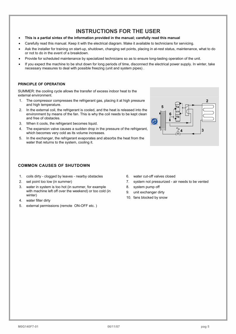
SUMMER: the cooling cycle allows the transfer of excess indoor heat to the external environment. 1. The compressor compresses the refrigerant gas, placing it at high pressure
and high temperature. 2. In the external coil, the refrigerant is cooled, and the heat is released into the
environment by means of the fan. This is why the coil needs to be kept clean and free of obstacles.
3. When it cools, the refrigerant becomes liquid. 4. The expansion valve causes a sudden drop in the pressure of the refrigerant,
which becomes very cold as its volume increases. 5. In the exchanger, the refrigerant evaporates and absorbs the heat from the
water that returns to the system, cooling it.
21a
34
5
61b
COMMON CAUSES OF SHUTDOWN 1. coils dirty - clogged by leaves - nearby obstacles 2. set point too low (in summer) 3. water in system is too hot (in summer, for example
with machine left off over the weekend) or too cold (in winter)
4. water filter dirty 5. external permissions (remote ON-OFF etc. )
6. water cut-off valves closed 7. system not pressurized - air needs to be vented 8. system pump off 9. unit exchanger dirty 10. fans blocked by snow
M0G
140F
7-01
06
/11/
07
pag
6
TO D
O F
OR
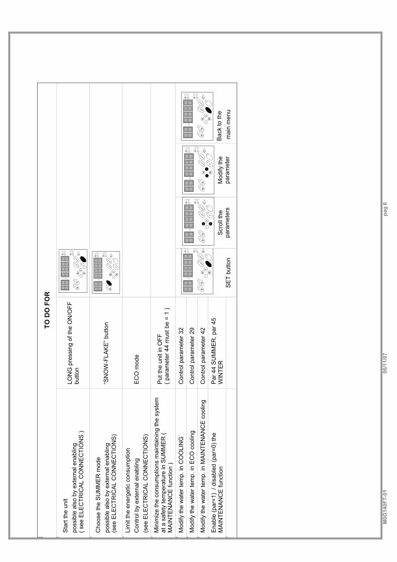
Sta
rt th
e un
it po
ssib
le a
lso
by e
xter
nal e
nabl
ing
( see
ELE
CTR
ICA
L C
ON
NE
CTI
ON
S )
LON
G p
ress
ing
of th
e O
N/O
FF
butto
n
ALARM
STATUS
SET
Cho
ose
the
SUM
MER
mod
e po
ssib
le a
lso
by e
xter
nal e
nabl
ing
(s
ee E
LEC
TRIC
AL
CO
NN
EC
TIO
NS
) “S
NO
W-F
LAK
E” b
utto
n
ALARM
STATUS
SET
Li
mit
the
ener
getic
con
sum
ptio
n C
ontro
l by
exte
rnal
ena
blin
g (s
ee E
LEC
TRIC
AL
CO
NN
EC
TIO
NS
) E
CO
mod
e
Min
imiz
e th
e co
nsum
ptio
ns m
aint
aini
ng th
e sy
stem
at
a s
afet
y te
mpe
ratu
re in
SU
MM
ER
( M
AIN
TEN
AN
CE
func
tion
)
Put
the
unit
in O
FF
( par
amet
er 4
4 m
ust b
e =
1 )
Mod
ify th
e w
ater
tem
p. in
CO
OLI
NG
C
ontro
l par
amet
er 3
2
Mod
ify th
e w
ater
tem
p. in
EC
O c
oolin
g C
ontro
l par
amet
er 2
9
Mod
ify th
e w
ater
tem
p. in
MA
INTE
NA
NC
E c
oolin
g C
ontro
l par
amet
er 4
2
Ena
ble
(par
=1)
/ dis
able
d (p
ar=0
) the
M
AIN
TEN
AN
CE
func
tion
Par
44
SU
MM
ER
, par
45
WIN
TER
ALARM
STATUS
SET
S
ET
butto
n
ALARM
STATUS
SET
Scr
oll t
he
para
met
ers
ALARM
STATUS
SET
Mod
ify th
e pa
ram
eter
ALARM
STATUS
SET
B
ack
to th
e m
ain
men
u
M0G
140F
7-01
06
/11/
07
pag
7
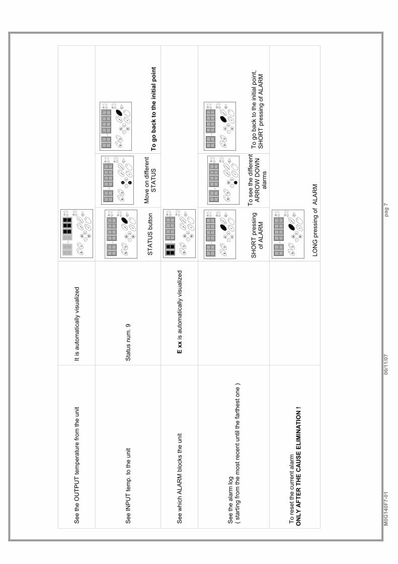
See
the
OU
TPU
T te
mpe
ratu
re fr
om th
e un
it It
is a
utom
atic
ally
vis
ualiz
ed
ALARM
STATUS
SET
See
INP
UT
tem
p. to
the
unit
Sta
tus
num
. 9
ALARM
STATUS
SET
STA
TUS
but
ton
ALARM
STATUS
SET
Mov
e on
diff
eren
t S
TATU
S
ALARM
STATUS
SET
To
go
back
to th
e in
itial
poi
nt
See
whi
ch A
LAR
M b
lock
s th
e un
it E
xx is
aut
omat
ical
ly v
isua
lized
ALARM
STATUS
SET
See
the
alar
m lo
g
( sta
rting
from
the
mos
t rec
ent u
ntil
the
farth
est o
ne )
ALARM
STATUS
SET
S
HO
RT
pres
sing
of
ALA
RM
ALARM
STATUS
SET
To
see
the
diffe
rent
A
RR
OW
DO
WN
al
arm
s
ALARM
STATUS
SET
To
go
back
to th
e in
itial
poi
nt,
SH
OR
T pr
essi
ng o
f ALA
RM
To re
set t
he c
urre
nt a
larm
O
NLY
AFT
ER T
HE
CA
USE
ELI
MIN
ATI
ON
!
ALARM
STATUS
SET
LON
G p
ress
ing
of A
LAR
M
M0G140F7-01 06/11/07 pag 8
GENERAL WARNINGSMANUAL PURPOSE This manual has been designed to enable the unit to be installed, started up and maintained correctly.
MANUAL INSTRUCTIONS It is essential to observe these instructions. The manufacturer declines all liability for any damage that may be caused whether directly or indirectly to persons or things if these instructions are not heeded.
MANUAL STORE This manual and the unit’s wiring diagram should be carefully stored so that they are readily available to the operator when required.
EXPERT PERSONAL The unit must be installed, tested and maintained by expert personal who meet the relevant legal requirements (Italian law No. 46 of 5/3/1990).
LOCAL SAFET REGULATION INSTALLATION The installation must be performed observing the local safety regulations.
POWER SUPPLY Make sure the power supply conforms to the data on the unit’s rating plate, located inside the door of the main electrical panel.
PACKAGING The packaging material (plastic bags, polystyrene foam, nails, etc.) is potentially dangerous and should therefore be kept away from children and recycled in compliance with the local regulations in force.
MAINTENANCE Before performing any service operations, cut off the power. Perform the operations in conformity with the local regulations in force.
PERIODICAL INSPECTIONS Perform periodical inspections to locate possible loosened or broken parts. If the repairs are not performed, there will be a higher risk for things and peoples to become damaged and injured.
FAULT – POOR OPERATION Switch off the unit in the event of faults or poor operation.
REPAIR Only have repairs carried out by a service centre authorised by the manufacturer, and insist on the use of original spare parts only. Failure to comply with the above may compromise the safety of the unit.
MODIFICATIONS The manufacturer will not accept any responsibility, and the warranty will lapse, in the event of electric and/or mechanical modifications. Any modification which is not formally authorized, and which does not respect the instructions given in this manual, will cause the warranty to lapse.
INTENDED USE The unit must only be used for the specific purpose it was designed : The unit is designed to cool/heat water or a water and glycol mix for air-conditioning, within the limits defined in the technical bulletin and this manual. Any use other than that specified does not imply any commitment or constraint by the manufacturer in any way whatsoever.
ADDITIONAL SAFETY PRECAUTIONS This unit has been especially designed and manufactured so to prevent any risk to persons and health hazard. For this reason, design solutions fit to eliminate (where possible) any cause of risk and sensibly reduce the probability of danger have been adopted. Please refer to the "Residual Risks" section of this manual and strictly observe the behaviour prescriptions listed there in order to prevent any possible risk that hasn’t been possible to avoid in the design stage.
DATA UPDATING
The manufacturer may be able to modify the data without prior notice as a consequence of constant improvements.
REGULATIONS AND CERTIFICATIONS UNI EN ISO 9001 CERTIFICATION Clivet S.p.A., in order to guarantee customer satisfaction, has chosen the ISO 9001 Quality System as the reference for all its business activities. This is demonstrated by the company’s commitment to ongoing improvements in the quality and reliability of its products; its sales, design, purchasing, production and after-sales service activities are the means used to reach such purpose.
CE MARK
Clivet products bear the CE mark, in compliance with the requirements of the following EC directives, including the latest amendments, and with the corresponding national approximated legislation: • - 98/37/CE • - 89/336/CEE as modified by the directives 92/31/CEE
and 93/68/CEE • - 73/23/CEE as modified by the directive 93/68/CEE • - 97/23/CE
M0G140F7-01 06/11/07 pag 9
RESIDUAL RISKS
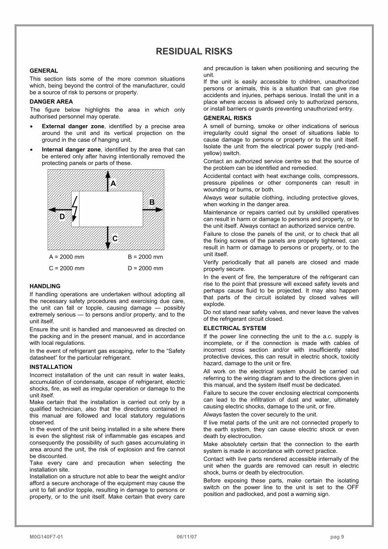
GENERAL This section lists some of the more common situations which, being beyond the control of the manufacturer, could be a source of risk to persons or property. DANGER AREA The figure below highlights the area in which only authorised personnel may operate. • External danger zone, identified by a precise area
around the unit and its vertical projection on the ground in the case of hanging unit.
• Internal danger zone, identified by the area that can be entered only after having intentionally removed the protecting panels or parts of these.
A
B
C
D
A = 2000 mm B = 2000 mm
C = 2000 mm D = 2000 mm HANDLING If handling operations are undertaken without adopting all the necessary safety procedures and exercising due care, the unit can fall or topple, causing damage — possibly extremely serious — to persons and/or property, and to the unit itself. Ensure the unit is handled and manoeuvred as directed on the packing and in the present manual, and in accordance with local regulations. In the event of refrigerant gas escaping, refer to the “Safety datasheet” for the particular refrigerant. INSTALLATION Incorrect installation of the unit can result in water leaks, accumulation of condensate, escape of refrigerant, electric shocks, fire, as well as irregular operation or damage to the unit itself. Make certain that the installation is carried out only by a qualified technician, also that the directions contained in this manual are followed and local statutory regulations observed. In the event of the unit being installed in a site where there is even the slightest risk of inflammable gas escapes and consequently the possibility of such gases accumulating in area around the unit, the risk of explosion and fire cannot be discounted. Take every care and precaution when selecting the installation site. Installation on a structure not able to bear the weight and/or afford a secure anchorage of the equipment may cause the unit to fall and/or topple, resulting in damage to persons or property, or to the unit itself. Make certain that every care
and precaution is taken when positioning and securing the unit. If the unit is easily accessible to children, unauthorized persons or animals, this is a situation that can give rise accidents and injuries, perhaps serious. Install the unit in a place where access is allowed only to authorized persons, or install barriers or guards preventing unauthorized entry. GENERAL RISKS A smell of burning, smoke or other indications of serious irregularity could signal the onset of situations liable to cause damage to persons or property or to the unit itself. Isolate the unit from the electrical power supply (red-and-yellow) switch. Contact an authorized service centre so that the source of the problem can be identified and remedied. Accidental contact with heat exchange coils, compressors, pressure pipelines or other components can result in wounding or burns, or both. Always wear suitable clothing, including protective gloves, when working in the danger area. Maintenance or repairs carried out by unskilled operatives can result in harm or damage to persons and property, or to the unit itself. Always contact an authorized service centre. Failure to close the panels of the unit, or to check that all the fixing screws of the panels are properly tightened, can result in harm or damage to persons or property, or to the unit itself. Verify periodically that all panels are closed and made properly secure. In the event of fire, the temperature of the refrigerant can rise to the point that pressure will exceed safety levels and perhaps cause fluid to be projected. It may also happen that parts of the circuit isolated by closed valves will explode. Do not stand near safety valves, and never leave the valves of the refrigerant circuit closed. ELECTRICAL SYSTEM If the power line connecting the unit to the a.c. supply is incomplete, or if the connection is made with cables of incorrect cross section and/or with insufficiently rated protective devices, this can result in electric shock, toxicity hazard, damage to the unit or fire. All work on the electrical system should be carried out referring to the wiring diagram and to the directions given in this manual, and the system itself must be dedicated. Failure to secure the cover enclosing electrical components can lead to the infiltration of dust and water, ultimately causing electric shocks, damage to the unit, or fire. Always fasten the cover securely to the unit. If live metal parts of the unit are not connected properly to the earth system, they can cause electric shock or even death by electrocution. Make absolutely certain that the connection to the earth system is made in accordance with correct practice. Contact with live parts rendered accessible internally of the unit when the guards are removed can result in electric shock, burns or death by electrocution. Before exposing these parts, make certain the isolating switch on the power line to the unit is set to the OFF position and padlocked, and post a warning sign.
M0G140F7-01 06/11/07 pag 10
Contact with parts that could become live when the unit is started up can result in electric shock, burns or death by electrocution. When there is no need for circuits to be powered up, set the isolating switch on the power line to the OFF position, padlock it and post a warning sign. MOVING PARTS Contact with the fan rotors can cause injury. Before removing the protective grilles or the fans themselves, make certain the isolating switch on the power line to the unit is set to the OFF position and padlocked, and post a warning sign. Before removing the protective grilles or the fans themselves, make certain the isolating switch on the power line to the unit is set to the OFF position and padlocked, and post a warning sign. REFRIGERANT In the event of safety valves coming into operation and releasing refrigerant gas, persons in the vicinity can be
injured or suffer toxic effects. Always wear suitable clothing and protective goggles when working in potential hazard areas. In the event of refrigerant gas escaping, refer to the “Safety datasheet” for the particular refrigerant. If an open flame or heat source is brought into contact with the refrigerant, or the pressurized gas circuit should overheat (e.g. during welding operations), this can cause explosion or fire. Do not position any heat source within the hazard area. Maintenance or repair operations involving welding must be carried out with the system emptied of refrigerant. WATER SYSTEM Defects affecting pipelines, connections or valves and other control componentry can result in water being leaked or sprayed from the system, occasioning damage to property or causing short circuits in the unit. Make certain all hydraulic connections are securely made, following the directions given in the present manual.
REFRIGERANT SAFETY CHARGE
R-410A
01
Identification of the product and of the supplier
Chart No FRIG 8 Product R-410A Identification of the supplier. See heading or bottom of page. No of emergency telephone. See heading or bottom of page.
02
Composition / information on ingredients
Substance/ Compound . Compound Elements / Impurities. It contains the following elements Difluorometan (R32) 50 % in weight Pentafluoroetan (R125) 50 % in weight CEE No Non applicable for mixtures. Commercial name /
03
Hazard identification
Hazard identification. Liquefied gas. Vapours are heavier than air and can cause choking by reducing the oxygen available for breathing. A rapid evaporation of the liquid can cause freezing. It can cause cardiac arrhythmia.
04
First aid measures
Inhalation. Do not administer anything to fainted people. Take to open air. Administer oxygen or practice artificial breathing if necessary. Do not administer adrenaline or similar substances. Contact with eyes. Rinse carefully with plenty of water for at least 15 minutes and consult a doctor. Contact with the skin. Rinse immediately with plenty of water. Immediately take off all contaminated cloths. Ingestion. Way of exposure not very probable.
05
Anti-fire measures Specific hazards. Pressure increase. Dangerous combustible products. Halogen acids, traces of carbonyl halogens. Extinction means. You can use all extinction means available. Special methods. Cool the containers/tanks with sprays of water. Special protection means. In close spaces, use the self-breather.
06
Measures against the accidental leakages of the product.
Personal protections. Evacuate the personnel in safety areas. Foresee adequate ventilation. Use means of personal protection. Protection for the environment. It evaporates. Methods for eliminating the product. It evaporates.
07
Handling and stocking.
Handling and stocking. Assure a sufficient exchange of air and/or a suction system in work areas. Use only in well-ventilated rooms. Do not breathe vapours or aerosols. Carefully close the containers and keep them in a cool, dry and well-ventilated place. Keep in the original containers. Incompatible products. Explosives, inflammable materials, organic peroxides.
08
Check of the exposition / personal protection
Personal protection. Assure adequate ventilation, especially in closed rooms. Control parameters. Difluorometan (R32): Recommended limits of exposition: AEL (8h and 12h TWA) = 1000 ml/m3 Pentafluoroetan (R125): Recommended limits of exposition: AEL (8h and 12h TWA) = 1000 ml/m3 Protection of respiratory tract. For the rescue and for service work in the tanks, use an autonomous breather. Vapours are heavier than the air and can cause choking by reducing the oxygen available for breathing. Protection for the eyes. Total protection glasses. Protection for the hands. Rubber gloves. Hygienic measures. Do not smoke.
M0G140F7-01 06/11/07 pag 11
09
Chemical -physical properties.
Relative density, gas (air=1) Heavier than air. Solubility in water (mg/l). Not known, but probably very low. Aspect. Colourless liquefied gas. Smell. Simile to ether. Point of ignition. Don’t ignite.
10 Stability and reactivity.
Stability and reactivity. No decomposition if used following the instructions. Materials to avoid. Alkaline metals, earth alkaline metals, granulated metal salts, Al, Zn, Be etc. in powder. Dangerous decomposition products. Halogen acids, traces of carbonyl halogens.
11
Toxicological information
Local effects. Concentration substantially above the TLV value (1000 ppm) can cause narcotic effects. Inhalation of products at high concentration decomposition can cause respiratory insufficiency (pulmonary edema). Long-term toxicity. It has shown no carcinogenic, teratogen or mutagenic effects on animal experiments. Specific effects. A rapid evaporation of the liquid can cause freezing. It can cause cardiac arrhythmia.
12 Ecological information
Effects connected to ecotoxicity Pentafluoroetan (R125) Potential of global heating of halocarbides; HGWP; (R-11 = 1) = 0.84 Potential of ozone impoverishment; ODP; (R-11 = 1) = 0
13
Disposal considerations
General considerations. Do not drain where the accumulation can be dangerous Usable as reconditioning. Depressurized containers should be given back to the supplier. Contact the supplier if the use of instructions is necessary.
14
Transport information
Designation for the transport LIQUEFIED GAS N.A.S (DIFLUOROMETAN, PENTAFLUOROETAN) UN No 3163 Class/Div 2.2 ADR /RID Nr 2, 2°A No hazard ADR/RID 20 ADR Label. Label 2: not toxic gas not inflammable. CEFIC Groupcard 20g39 - A Other information for the transport. Avoid the transport on vehicles where the loading zone is not separated from the driver compartment. Verify that the driver is informed on the potential risk of the load and that he knows what to do in case of an accident or emergency. Before starting the transport, verify that the load is well fixed and: Verify that the container valve is closed and does not leak Verify that the blind cap of the valve, if supplied, is correctly assembled. Verify that the cap (if supplied) is well assembled and that there is adequate ventilation Verify that the norms in force are respected.
15
Information on the norms in force
The product must be labelled according to the 1999/45/CE normative. Observe the following norms, the relevant updating and the applicable modifications: Circulars no.46/79 and 61/81 of the Work Ministry: risks connected to the use of products containing aromatic ammines. Law Decree no. 133/92 : Norms relevant to the draining of dangerous substances in water Law Decree no. 277/91: Protection of workers for noise, lead and amianthus Law 256/74, Ministerial Decree of 28th Jan. 1992, Legislative Decree no 52 of 3rd Feb. 1997, Ministerial Decree of 28th Apr. 1997 and following modifications: Classification, packaging and labelling of compounds and dangerous substances Decree of the Republic President no.175/88, following modifications and updating: Activities with risks of serious accidents (Seveso Law) Decree of the Republic President no 203/88: Emissions in the atmosphere Decree of the Republic President no.303/56: Hygiene of work Decree of the Republic President no.547/55: Norms concerning the accident prevention Legislative Decree. No.152 of 11th May 1999: Protection of waters.
16
Other information Suggested uses. Refrigerant. High concentrations can cause asphyxia. Keep in a dry and well-ventilated place. Do not breathe in the gas. The asphyxia risk is often under-evaluated and must be put into evidence during the operator’s training.
Verify that all national and regional regulations are observed. Before using this product in any new process or experiment, a deep study about the safety and the product compatibility with the materials must be performed. The above information is based on our present know-how and describes the product considering the safety needs. However, they do not represent a guarantee and a warranty of the qualities in a juridical sense. Everyone is personally responsible for the observation of these norms. Information present in this document is valid at the time of printing. The company is not responsible for any damages caused by the incorrect use of the product and/or for the use in conditions different from the conditions suggested.
M0G140F7-01 06/11/07 pag 12
RECEPTIONINSPECTION UPON RECEPTION Check on arrival that the unit has not suffered damage during transit and that it is complete in every part as specified in the order. In the event of visible damage/deficiencies being discovered, make a note immediately on the delivery document with the comment: CONDITIONAL ACCEPTANCE — CLEAR EVIDENCE OF DEFICIENCIES/DAMAGE DURING TRANSIT Inform both the supplier and the carrier of the details by fax and by registered mail with advice of receipt not later than 8 days after taking consignment. Notifications sent after 8 days have elapsed will be ignored.
STORAGE Shelter from: direct sunlight, rain, sand and wind Temperature: maximum 60°C minimum -10°C Maximum humidity: 90% The respect of the instructions on the exterior side of the packaging assures the physical and functional integrity of the unit for the final user’s advantage. It is recommended to: • Handle carefully • Keep in a dry place • Avoid putting other objects on top of the unit (respect
the limits of levels of superimposition shown in the package)
• Avoid placing the unit with thermoretractable protection under the sun since the pressure of the circuits can assume values which activate the safety valves.
HANDLING The operation of handling the unit must be carried out respecting the instructions of the safety norms in force (Legislative Decree 626/94 and following modifications) Before starting the handling operations: • Value the critical points during handling (stairs, flights,
disconnected routes, doors, etc) • Verify that the lifting capacity of the means used is
adequate to the unit weight • Consider that the barycentre could be moved with
respect to the center of the unit • Before starting to lift, verify that the unit is at a stable
balance The following examples are indications; the choice of the means and of the handling modes will depend on factors, such as: • The unit weight • Type and overall dimensions of the unit • Place and route for the handling (dirt yard, asphalted
square, etc) • Condition of the place of destination (roof, square, etc) • Handling distance characteristics (distances, flights,
steps, doors)
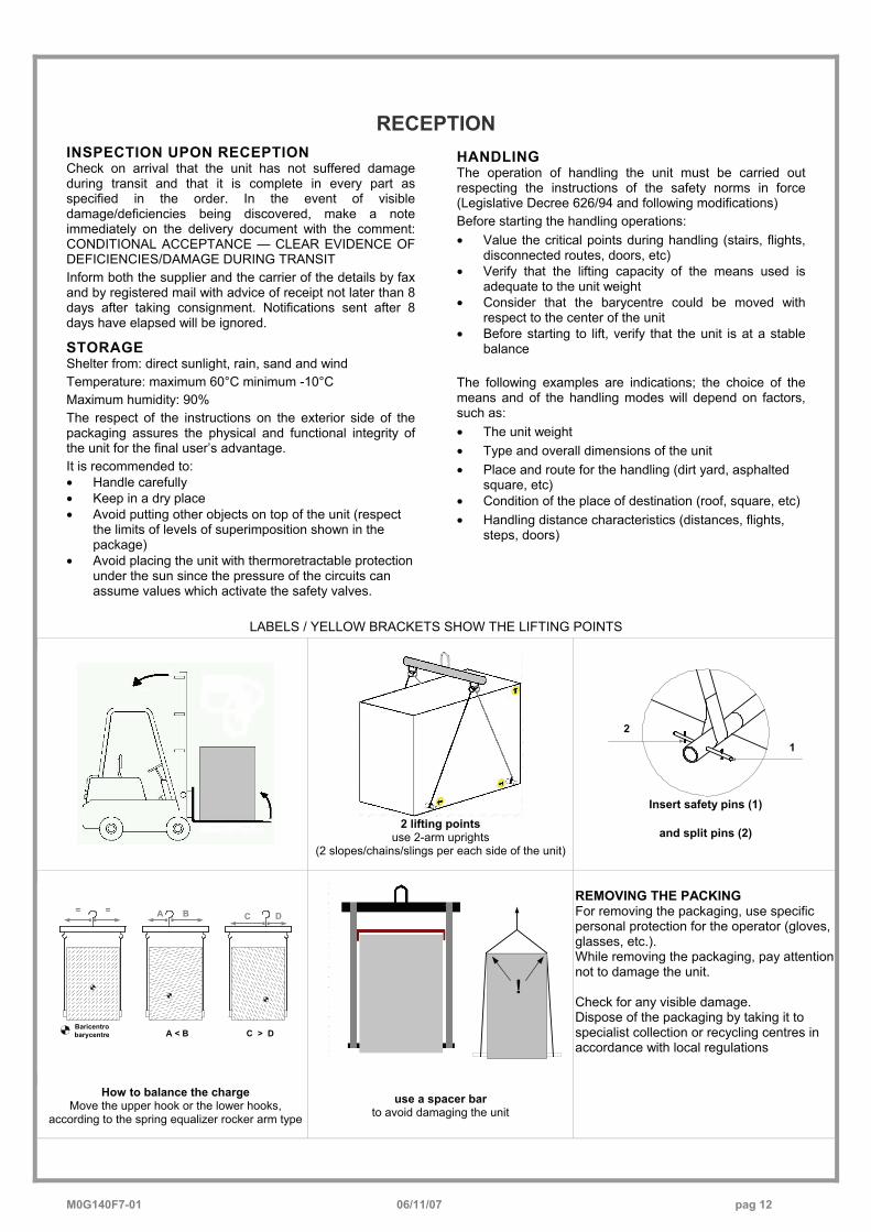
LABELS / YELLOW BRACKETS SHOW THE LIFTING POINTS
2 lifting points use 2-arm uprights
(2 slopes/chains/slings per each side of the unit)
12
Insert safety pins (1)
and split pins (2)
C > D
DCBA
A < B
= =
Baricentrobarycentre
!
REMOVING THE PACKING For removing the packaging, use specific personal protection for the operator (gloves, glasses, etc.). While removing the packaging, pay attention not to damage the unit. Check for any visible damage. Dispose of the packaging by taking it to specialist collection or recycling centres in accordance with local regulations
How to balance the charge Move the upper hook or the lower hooks,
according to the spring equalizer rocker arm type
use a spacer bar to avoid damaging the unit
M0G140F7-01 06/11/07 pag 13
POSITIONINGGENERAL For installing air-conditioning systems, it is necessary to consider the following: • the technical spaces necessary for the machine and
system • the place where the machine will be installed • the transport of thermal carrier fluids and relevant
connections to the unit: o water o air o refrigerant (unit in more sections)
• electrical connections If these aspects are not evaluated carefully, they can affect the performances and the working life of the unit.
FUNCTIONAL CLEARANCES When placing the unit, please respect the functional clearances indicated in DIMENSIONS section. The functional spaces need to be observed because of the following: • to guarantee the good operation of the unit • to allow the performance of all maintenance operations • to protect the authorized operators and exposed
people If more units are placed close to one another, the functional spaces must be doubled.
POSITIONING 1. The units are designed for OUTDOOR installations,
performed in fixed positions and in areas accessible only to qualified and authorized personnel
2. SAFETY VALVE (only if present on the unit) : the installer is responsible for evaluating the opportunity of installing drain tubes, in conformity with the local regulations in force ( EN 378 ) For the valves fitted directly on the tandem, the pipe must be equipped with antivibration mounts
3. Install the unit raised from the ground 4. avoid installations in places subject to flooding 5. Consider the maximum level which can be reached by
snow 6. Verify that the fixing/supporting points are level and
suitable to support the weight of the unit (see the weight and the weights distribution)
7. It is recommended to put the unit on specific antivibration devices Each support point of the unit sustains a different weight. Therefore, each anti-vibration device is sized for a specific support point, and can only be placed there. The anti-vibration devices must therefore be placed in accordance with the instructions provided with them and with the dimensional drawings in which the support points are indicated by W1 , W2 , W3 etc . On each anti-vibration device (if provided by CLIVET), its identifying code is stamped, for example C6100100 Flexible joints are necessary on all the hydraulic/ aeraulic connections (the joints are not supplied by Clivet)
8. Anchor the unit to the ground; foresee windbreak
barriers in case of places where there are strong prevalent winds .
9. The choice of the location of the unit is of fundamental importance for correct operation; to avoid: − obstacles that block the flow of air − difficulty in air circulation − leaves or other objects that may block the
exchanger coils − winds that contrast or excessively assist the air
flow − phenomena of stratification or air re-circulation − nearby sources of heat (chemney, extractor ecc)
− positioning under the round level or near very high walls
The previous situations cause working anomalies or stop the machine and cause:
− during SUMMER operation, increase of the condensation pressure with the decay of performances and possible stops due to high pressure.
M0G140F7-01 06/11/07 pag 14
!
Tree
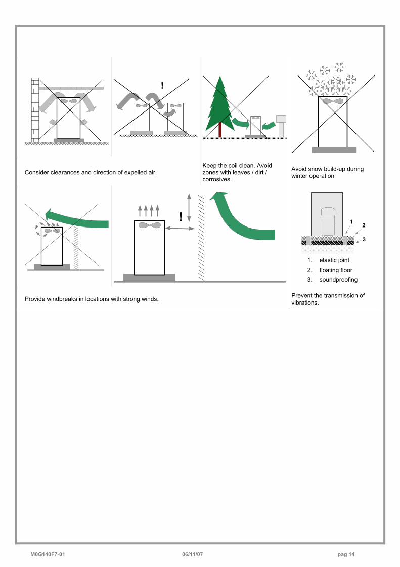
Consider clearances and direction of expelled air. Keep the coil clean. Avoid zones with leaves / dirt / corrosives.
Avoid snow build-up during winter operation
!
1
3
2
1. elastic joint 2. floating floor 3. soundproofing
Provide windbreaks in locations with strong winds. Prevent the transmission of vibrations.
M0G140F7-01 06/11/07 pag 15
WATER CONNECTIONS
GENERAL Piping must be designed with the least possible number of bends and head variations. If the pressure chute of the installation is above the useful prevalence of the pump, the water delivery capacity is reduced as well as, as a consequence, the thermal exchange and the yield. INTERCEPTING VALVES Install on the input and output of the user parts (exchangers, coils, humidifiers, etc) So that it will be possible to carry out all the service operations and possible substitutions without emptying the installation. PRESSURE AND TEMPERATURE INDICATOR Install on the input and output of the user parts (exchangers, coils, humidifiers, etc) So that it will be possible to carry out all the service operations. AUTOMATIC OR MANUAL ESCAPE VALVES Install the highest points of tubes in a way that the air can escape form the circuit. BLEEDING COCK Install them at the lowest points of the circuit, so as to allow emptying. LEAKAGE TESTS Before performing the insulation of the tubes, carry out a leakage test. TUBE INSULATION All tubes of water must be insulated so that to avoid the formation of condensation and thermal dispersions along the tubes themselves. Verify that the insulation is the vapour coil type. The connections for the air escape and for the emptying must be out of the insulating thickness to assure the accessibilità. CONNECTIONS SUPPORTS The weight of the hydraulic connections must be supported in the exterior of the unit so as not to stress the connections of user devices (exchangers, coils, humidifiers, etc ) .
ANTI-VIBRATION DEVICES In case of units with anti-vibration devices, it is necessary to assemble elastic joints, even on water connections. RISK OF FREEZE If the unit and the relevant water connections are subject to temperatures near 0°C: • mix the water of the system with glycol • protect the tubes with heating cables under the tubes
insulation • empty the system by verifying that:
o no taps are closed so they can not trap the water, even after emptying
o there are no low points where the water can stagnate even after emptying; blow if necessary
INTALLATION EMPTYING The refilling of the water present in the installation increase the oxidation phenomena and lime deposits. If necessary empty only the interested system section and anyway empty or refill the installation if necessary . EXPANSION TANK The installation must be kept at the right pressure by both an expansion tank and a combined valve of pressure reduction and discharge; if the components are present on the unit, they must be installed on the installation. The expansion tank must be dimensioned in function of the water in the installation. MAX. WORKING PRESSURE • max. water side pressure = 550kPa ARIES EFFECTS AND AIR BUBBLES CAN PRODUCE THE OVERCOMING AND CAUSE WATER DROPS
EXCHANGER USE SIDE
FILTER It is very important for the water to be free of impurities. If it is not, the efficiency of thermal exchange is diminished. In worst cases, the exchanger can be irreparably damaged. If the filter is not present on the machine, it must be immediately installed upstream from the unit, in a position which can be easily reached for cleaning FLOW SWITCH The flow switch must be present as a component of the system, so as to ensure shutdown of the unit if water is not circulating. It must be installed in a straight tract of the tubes, not near the elbows, which can generate harmful turbulence
UNFREEZABLE LIQUIDS If the unit is used when the water temperature is lower than + 4°C, avoid the formation of ice by using unfreezable liquids (ex. Ethilenic Glycol) in the necessary percentage. The use must also be determined for ambient temperatures near 0°C . ANTIFREEZE HEATERS If the unit is equipped with antifreeze heaters on the exchanger side (standard or optional according to the models), verify that they are electrically fed during periods that the machine is stopped (night, weekends, long stops) WASHING THE SYSTEM Carefully wash the system by using clean water and discharge it before connecting the unit.

M0G140F7-01 06/11/07 pag 16
DIAGRAM OF RECOMMENDED USE SIDE CONNECTION Depending on the type of machine and the selected setup, some components may be integrated into the unit.
P
9
11
148
F
23
5
12
764
81
10
13
P
7
1. Charged system pressure switch
2. vent 3. pump 4. expansion tank 5. safety valve 6. flow switch 7. pressure switch / thermometer
8. filter 9. filling valve 10. antivibration joints 11. user side exchanger 12. Differential pressure
switch 13. Discharge cock 14. inertial storage tank
The accumulation tank is necessary in the event of the following: • the water in the system is very low • the unit will not be used in a private house (in an industrial process or other)
WATER CIRCUIT EMPTYING
The unit is equipped with outlets for the pump emptying and storage. Outlets are accessible from the rear side (left side in the figure). Storage content: size 82÷122 80 litres (optional) size 162÷302 130litres
RECOVERY EXCHANGER OPTIONAL - The unit can be equipped with exchangers to recover the condensation heat. The recovery can be: PARTIAL • with 25% recovery • The customer is responsible for the management of the
circulation pump, valves, thermostats, etc The recovery input water must not be below 25°C, in the event that, wrongful operations and breakages of the unit can occur . Water connections must be performed carefully as for the evaporator (filter, circuit washing, etc) .
Perform all necessary interventions to avoid the RISK OF FREEZING (tubes insulation, emptying of circuit, addition of glycol, anti-freeze heaters) . Water temperature can reach high temperatures (up to 100°C), therefore: • avoid the RISK OF BURNS by adopting the necessary
precautions (insulation of tubes, temperature detecting station on water if the sanitary use is foreseen, etc)
• Install safety valves and specifically dimensioned expansion tanks in the hydraulic circuit.
M0G140F7-01 06/11/07 pag 17
ELECTRICAL CONNECTION
GENERAL The characteristics of the electrical lines and relevant components must be determined by SPECIALIZED PERSONNEL ABLE TO DESIGN ELECTRICAL INSTALLATIONS; moreover, the lines must be in conformity with professional procedures and the regulations in force. All electrical operations should be performed by trained PERSONNEL HAVING THE NECESSARY REQUISITES UNDER LAW and being informed about the risks relevant to these activities. Before performing any operation on the electrical system, make sure that the unit supply line is SELECTED AT START. The earth connection must be made prior to other electrical connections. For all electrical type operations, REFER TO THE ELECTRICAL DIAGRAM ATTACHED TO THE UNIT; the number of the diagram is shown on the registration plate positioned on the electrical board or next to it. The electrical diagram should be carefully kept together with this manual and should be AVAILABLE FOR FUTURE INTERVENTION ON THE UNIT.
LINE OF UNIT POWER SUPPLY The ELECTRICAL DATA OF THE UNIT are shown in the technical chart of this manual and on the unit registration plate. The presence of accessories can vary according to the unit; the electrical data shown in the technical chart
refer to standard units. In the event of differences between the data of the registration plate and the data shown in this manual, as well as in the technical chart, please refer to the DATA SHOWN IN THE REGISTRATION PLATE. The protection device of the unit power supply line should break off the short circuit power whose value should be determined according to the plant features. The section of supply cables and protection cable must be seized according to the characteristics of the protections used.
SIGNALS / DATA LINES Do not overpass the maximum power allowed, which varies, according to the type of signal. Lay the cables far from power cables or cables having a different tension and that are able to emit electromagnetic disturbances. Do not lay the cable near devices which can generate electromagnetic interferences. Do not lay the cables parallel to other cables; cable crossings are possible, only if laid at 90°. Connect the screen to the ground, only if there are no disturbances Assure the continuity of the screen during the entire extension of the cable. Observe, if any, the requirements about impendency, capacity, attenuation
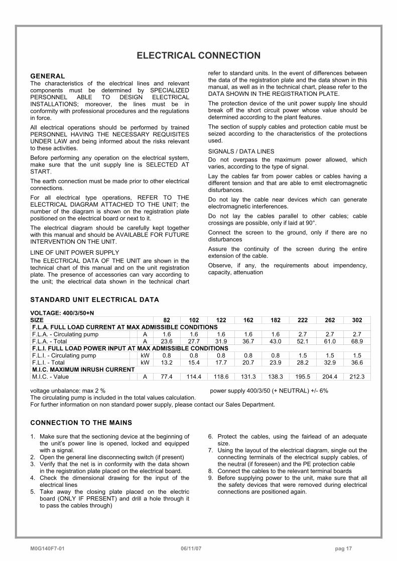
STANDARD UNIT ELECTRICAL DATA VOLTAGE: 400/3/50+N SIZE 82 102 122 162 182 222 262 302 F.L.A. FULL LOAD CURRENT AT MAX ADMISSIBLE CONDITIONS F.L.A. - Circulating pump A 1.6 1.6 1.6 1.6 1.6 2.7 2.7 2.7 F.L.A. - Total A 23.6 27.7 31.9 36.7 43.0 52.1 61.0 68.9 F.L.I. FULL LOAD POWER INPUT AT MAX ADMISSIBLE CONDITIONS F.L.I. - Circulating pump kW 0.8 0.8 0.8 0.8 0.8 1.5 1.5 1.5 F.L.I. - Total kW 13.2 15.4 17.7 20.7 23.9 28.2 32.9 36.6 M.I.C. MAXIMUM INRUSH CURRENT M.I.C. - Value A 77.4 114.4 118.6 131.3 138.3 195.5 204.4 212.3
voltage unbalance: max 2 % power supply 400/3/50 (+ NEUTRAL) +/- 6% The circulating pump is included in the total values calculation. For further information on non standard power supply, please contact our Sales Department.
CONNECTION TO THE MAINS 1. Make sure that the sectioning device at the beginning of
the unit’s power line is opened, locked and equipped with a signal.
2. Open the general line disconnecting switch (if present) 3. Verify that the net is in conformity with the data shown
in the registration plate placed on the electrical board. 4. Check the dimensional drawing for the input of the
electrical lines 5. Take away the closing plate placed on the electric
board (ONLY IF PRESENT) and drill a hole through it to pass the cables through)
6. Protect the cables, using the fairlead of an adequate size.
7. Using the layout of the electrical diagram, single out the connecting terminals of the electrical supply cables, of the neutral (if foreseen) and the PE protection cable
8. Connect the cables to the relevant terminal boards 9. Before supplying power to the unit, make sure that all
the safety devices that were removed during electrical connections are positioned again.
M0G140F7-01 06/11/07 pag 18
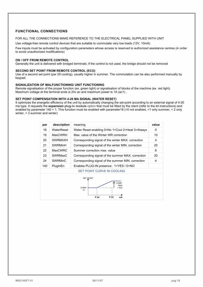
FUNCTIONAL CONNECTIONS FOR ALL THE CONNECTIONS MAKE REFERENCE TO THE ELECTRICAL PANEL SUPPLIED WITH UNIT Use voltage-free remote control devices that are suitable to commutate very low loads (12V, 10mA) Few inputs must be activated by configuration parameters whose access is reserved to authorized assistance centres (in order to avoid unauthorized modifications) ON / OFF FROM REMOTE CONTROL Generally the unit is delivered with bridged terminals; if the control is not used, the bridge should not be removed SECOND SET POINT FROM REMOTE CONTROL (ECO) Use of a second set point (par 29 cooling), usually higher in summer. The commutation can be also performed manually by keypad. SIGNALIZATION OF MALFUNCTIONING/ UNIT FUNCTIONING Remote signalisation of the proper function (ex. green light) or signalisation of blocks of the machine (ex. red light). Maximum voltage at the terminal ends is 24v ac and maximum power is 1A (ac1) . SET POINT COMPENSATION WITH 4-20 MA SIGNAL (WATER RESET) It optimizes the energetic efficiency of the unit by automatically changing the set-point according to an external signal of 4-20 ma type. It requests the expansion plug-in module option that must be fitted by the client (refer to the kit instructions) and enabled by parameter 140 = 1. This function must be enabled with parameter18 (=0 not enabled, =1 only summer, = 2 only winter, = 3 summer and winter)
par description meaning value 18 WaterReset Water Reset enabling 0=No 1=Cool 2=Heat 3=Always 0
19 MaxCWRH Max. value of the Winter WR correction 10
20 SWRMAXH Corresponding signal of the winter MAX. correction 4
21 SWRMinH Corresponding signal of the winter MIN. correction 20
22 MaxCWRC Summer correction max. value 8
23 SWRMaxC Corresponding signal of the summer MAX. correction 20
24 SWRMinC Corresponding signal of the summer MIN. correction 4
140 PlugInEn Enables PLUG-IN presence . 1=YES / 0=NO
SET POINT CURVE IN COOLING
mAP 23P 24
COMP.MAX
= P22COMP.=0
SET POINT
M0G140F7-01 06/11/07 pag 19
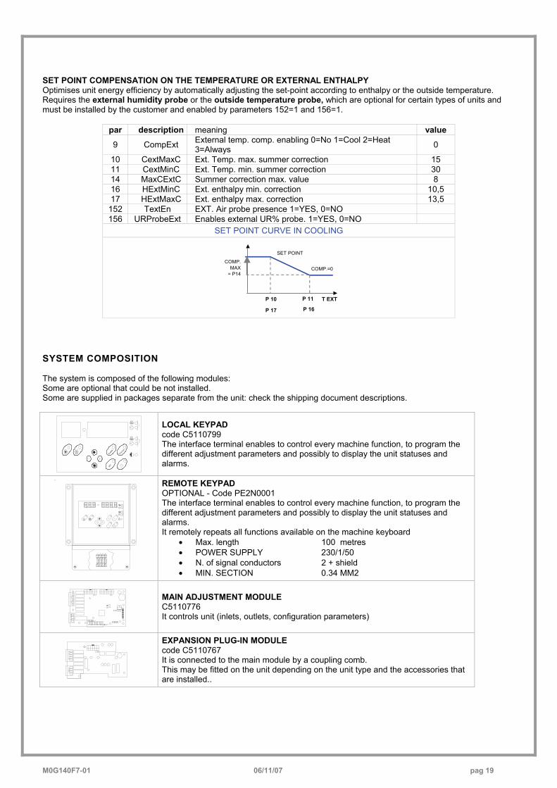
SET POINT COMPENSATION ON THE TEMPERATURE OR EXTERNAL ENTHALPY Optimises unit energy efficiency by automatically adjusting the set-point according to enthalpy or the outside temperature. Requires the external humidity probe or the outside temperature probe, which are optional for certain types of units and must be installed by the customer and enabled by parameters 152=1 and 156=1.
par description meaning value
9 CompExt External temp. comp. enabling 0=No 1=Cool 2=Heat 3=Always 0
10 CextMaxC Ext. Temp. max. summer correction 15 11 CextMinC Ext. Temp. min. summer correction 30 14 MaxCExtC Summer correction max. value 8 16 HExtMinC Ext. enthalpy min. correction 10,5 17 HExtMaxC Ext. enthalpy max. correction 13,5
152 TextEn EXT. Air probe presence 1=YES, 0=NO 156 URProbeExt Enables external UR% probe. 1=YES, 0=NO
SET POINT CURVE IN COOLING
T EXT P 11P 10
COMP.MAX
= P14COMP.=0
SET POINT
P 17 P 16
SYSTEM COMPOSITION The system is composed of the following modules: Some are optional that could be not installed. Some are supplied in packages separate from the unit: check the shipping document descriptions.
ALARM
STATUS
SET
LOCAL KEYPAD code C5110799 The interface terminal enables to control every machine function, to program the different adjustment parameters and possibly to display the unit statuses and alarms.
L N 91 92
STATUS
SET
ALARM
2
1
REMOTE KEYPAD OPTIONAL - Code PE2N0001 The interface terminal enables to control every machine function, to program the different adjustment parameters and possibly to display the unit statuses and alarms. It remotely repeats all functions available on the machine keyboard
• Max. length 100 metres • POWER SUPPLY 230/1/50 • N. of signal conductors 2 + shield • MIN. SECTION 0.34 MM2
MAIN ADJUSTMENT MODULE C5110776 It controls unit (inlets, outlets, configuration parameters)
EXPANSION PLUG-IN MODULE code C5110767 It is connected to the main module by a coupling comb. This may be fitted on the unit depending on the unit type and the accessories that are installed..
M0G140F7-01 06/11/07 pag 20
81 2 3 4 5 6 7
CN
2
12109 11
16
+5V 13
1415
gnd
1917
1821
20
SERIALETTL / RS485
CN
1 gnd
12V
AC+
-
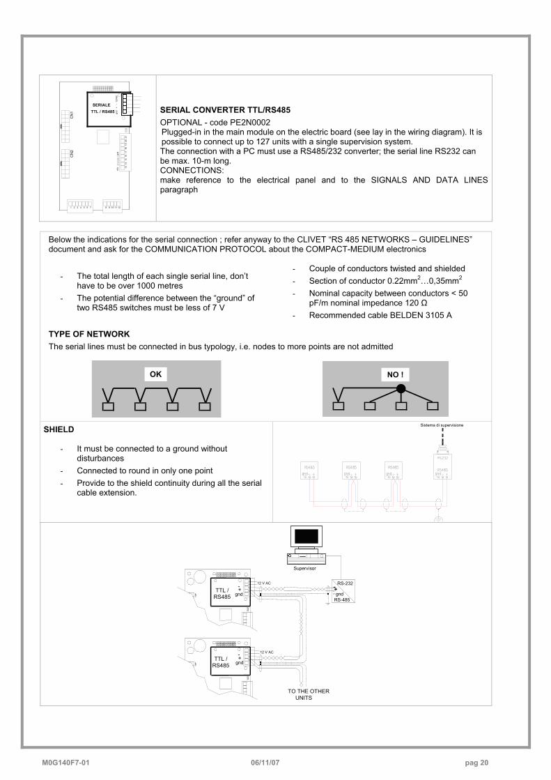
SERIAL CONVERTER TTL/RS485 OPTIONAL - code PE2N0002 Plugged-in in the main module on the electric board (see lay in the wiring diagram). It is possible to connect up to 127 units with a single supervision system. The connection with a PC must use a RS485/232 converter; the serial line RS232 can be max. 10-m long. CONNECTIONS: make reference to the electrical panel and to the SIGNALS AND DATA LINES paragraph
Below the indications for the serial connection ; refer anyway to the CLIVET “RS 485 NETWORKS – GUIDELINES” document and ask for the COMMUNICATION PROTOCOL about the COMPACT-MEDIUM electronics
- The total length of each single serial line, don’t have to be over 1000 metres
- The potential difference between the “ground” of two RS485 switches must be less of 7 V
- Couple of conductors twisted and shielded - Section of conductor 0.22mm2…0,35mm2 - Nominal capacity between conductors < 50
pF/m nominal impedance 120 Ω - Recommended cable BELDEN 3105 A
TYPE OF NETWORK The serial lines must be connected in bus typology, i.e. nodes to more points are not admitted
OK
NO !
SHIELD
- It must be connected to a ground without disturbances
- Connected to round in only one point - Provide to the shield continuity during all the serial
cable extension.
Sistema di supervisione
12 V AC
C N 1
C N 1
19
18
20
21
20
18
19
21
RS-485
RS-232
gnd-+
Supervisor
TTL /RS485
+-
TO THE OTHERUNITS
12 V AC
gnd
TTL / RS485
-gnd+
M0G140F7-01 06/11/07 pag 21
START-UP ALL THE EQUIPMENT MUST BE COMMISSIONED BY AUTHORISED SERVICE CENTRES.
THIS SERVICE IS LIMITED TO START-UP OF THE UNIT ONLY AND NOT THE CONNECTIONS OR INSTALLATION OF THE SYSTEM.
ONLY QUALIFIED TECHNICIANS MUST PERFORM THE FOLLOWING OPERATIONS.
PRELIMINARY CHECKS Before checking, please verify the following 1. the unit should be installed properly and in conformity
with this manual. 2. the electrical power supply line should be sectioned at
the beginning. 3. the sectioning device is locked and the proper warning
“not to operate” sign is placed on the handle. 4. make sure no tension is present 5. the coils must be clean and free of obstacles 6. the ventilators must be free of leaves, cardboard, fixed
obstacles (beams, barriers, etc.), snow, etc 7. the external ventilators must not be blocked
The external ventilators can be subject to a temporary block, especially if the inactivity period before the first start-up was quite long or if outside temperature is very low. It is also possible to unblock them manually (ONLY WHEN THE UNIT IS UNPLUGGED – RISK OF INJURES) so that jams or electric overloads are avoided when the unit is restarted.
REFRIGERANT SYSTEM Carefully check the refrigerating circuit: the presence of oil stains can mean leakage caused by transportation, movements or other). Open the cocks of the refrigerator circuit, if there are any. Using the unit manometers, if present, or service manometers, verify that the refrigerating circuit is in pressure. Make sure that all the service outlets are closed with proper caps; if caps are not present a leak of refrigerant can be possible.
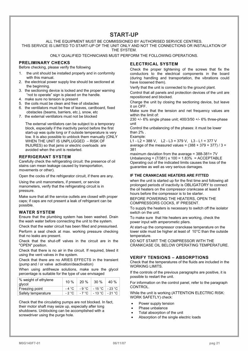
WATER SYSTEM Ensure that the plumbing system has been washed. Drain the wash water before connecting the unit to the system. Check that the water circuit has been filled and pressurised. Perform a seal check at max. working pressure checking that no leaks are present. Check that the shut-off valves in the circuit are in the "OPEN" position. Check that there is no air in the circuit. If required, bleed it using the vent valves in the system. Check that there are no ARIES EFFECTS in the transient (pump and / or valve activation/deactivation) When using antifreeze solutions, make sure the glycol percentage is suitable for the type of use envisaged % weight of ethylene glycol 10 % 20 % 30 % 40 %
Freezing point - 4 °C - 9 °C - 15 °C - 23 °C Safety temperature - 2 °C - 7 °C - 13 °C - 21 °C Check that the circulating pumps are not blocked. In fact, their motor shaft may seize up, especially after long shutdowns. Unblocking can be accomplished with a screwdriver using the purge hole.
ELECTRICAL SYSTEM Check the proper tightening of the screws that fix the conductors to the electrical components in the board (during handling and transportation, the vibrations could have loosened them). Verify that the unit is connected to the ground plant. Control that all panels and protection devices of the unit are repositioned and blocked. Charge the unit by closing the sectioning device, but leave it on OFF. Make sure that the tension and net frequency values are within the limit of: 230 +/- 6% single phase unit; 400/3/50 +/- 6% three-phase unit Control the unbalancing of the phases: it must be lower than 2% . Example: L1 - L2 = 388 V, L2 - L3 = 379 V, L3 - L1 = 377 V average of the measured values = (388 + 379 + 377) / 3 = 381 maximum deviation from the average = 388-381= 7V Unbalancing = (7/381) x 100 = 1.83% = ACCEPTABLE Operating out of the indicated limits causes the loss of the guarantee as well as very serious damages. IF THE CRANKCASE HEATERS ARE FITTED when the unit is started up for the first time and following all prolonged periods of inactivity is OBLIGATORY to connect the oil heaters on the compressor crankcase at least 8 hours before the compressor is to be starter. BEFORE POWERING THE HEATERS, OPEN THE COMPRESSORS COCKS, IF PRESENT. To supply the heaters is necessary to switch off the isolator switch on the unit. To make sure that hte heaters are working, check the power input with amperometic pliers. At start-up the compressor cranckase temperature on the lower side must be higher at least of 10°C than the outside temperature. DO NOT START THE COMPRESSOR WITH THE CRANKCASE OIL BELOW OPERATING TEMPERATURE.
VERIFY TENSIONS – ABSORPTIONS Check that the temperatures of the fluids are included in the WORKING LIMITS. If the controls of the previous paragraphs are positive, it is possible to restart the unit. For information on the control panel, refer to the paragraph CONTROL. While the unit is working (ATTENTION ELECTRIC RISK: WORK SAFETLY) check: • Power supply tension • Phase unbalance • Total absorption of the unit • Absorption of the single electric loads
M0G140F7-01 06/11/07 pag 22
UNIT EQUIPPED WITH SCROLL COMPRESSORS The GENERAL TECHNICAL DATA table shows the type of compressor on the unit. The Scroll compressors have only one direction of rotation. In the event that the direction is reversed, the compressor will not be damaged, but its noisiness will increase and pumping will be negatively affected. After a few minutes, the compressor will stop because of the activation of the thermal protection. In this event, cut the power and reverse the 2 phases on the machine power. Prevent the compressor from working with in reverse rotation: more than 2-3 anomalous starts up can damage it. Make sure the direction of rotation is correct, measure the condensation and suction pressure. Pressure must clearly differ: at the start, the suction pressure decreases whilst the condensation pressure increases. The phase optional monitor, which controls the phase sequence, can be installed later.
REMOTE INPUT CONFIGURATIONS Check used remote inputs are activated (ON-OFF etc.) as given in the instructions in the ELECTRIC WIRING chapter.
SETTING THE SET-POINT Check if it is necessary to modify the set-points shown in the CONTROL chapter
EVAPORATOR WATER FLOW RATE Check that the difference between the temperature of exchanger return and supply water corresponds to power according to this formula:
unit cooling power (kW) x 860 = Dt (°C) x flow rate (L/h). The cooling power is shown in the TABLE ON GENERAL TECHNICAL DATA included in this manual, referred to specific air/water conditions, or in the tables on cooling PERFORMANCE IN THE TECHNICAL BULLETIN referred to various conditions of use. Check for water side exchanger pressure drops:
• Determine the water flow rate. • Measure the difference in pressure between
exchanger input and output and compare it with the graph on WATER SIDE EXCHANGER PRESSURE DROPS.
The measurement of pressure will be easier if pressure gauges are installed as indicated in the DIAGRAM OF SUGGESTED WATER CONNECTIONS .
REFRIGERANT CIRCUIT PARAMETER CHECK Detecting the operational conditions is useful to control the unit along time: the performed records must be kept and be available during maintenance interventions. When the unit works in stable conditions and according to the operating limits, take note of the following data: 1. compressor diacharge temperature (WARNING –
BURN DANGERI) 2. condensing pressure 3. liquid temperature 4. dehydrator filter upstream and downstream
temperature 5. return pressure 6. return temperature 7. exchanger input water temperature 8. exchanger output water temperature 9. external air temperature (coil input) 10. air temperature coming out from fans
M0G140F7-01 06/11/07 pag 23
CONTROL
The HEATING mode functions are active only on HEAT PUMP unit version .
In ONLY COOL units, the relative parameters are VISIBLE but NOT ACTIVE , for example the winter setpoint. ALA
RM
STATUS
SET
OPERING MODES
ON – OFF
Unit can be switched on and off by: remote or service keypad remote switch (see ELECTRICAL CONNECTIONS paragraph) Supervisor
COOLING The compressor is activated with supply temperature higher than set point
ECO A secondary set-point can be used, with respect to the comfort setting. In heating the ECO-set is lower than the standard set , in cooling the ECO-set is higher than the standard set.
MAINTENANCE the plant can be kept within the operating limits even when the unit is OFF or on STANDBY
CHARACTERISTICS
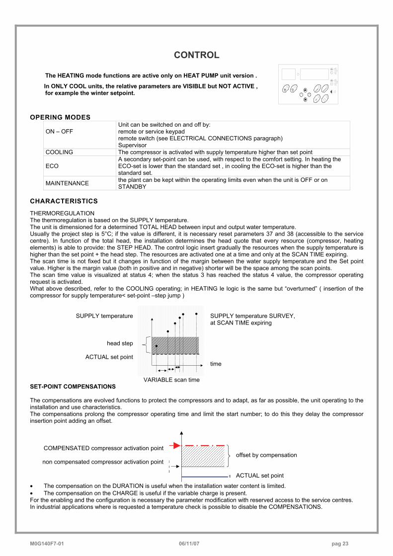
THERMOREGULATION The thermoregulation is based on the SUPPLY temperature. The unit is dimensioned for a determined TOTAL HEAD between input and output water temperature. Usually the project step is 5°C; if the value is different, it is necessary reset parameters 37 and 38 (accessible to the service centre). In function of the total head, the installation determines the head quote that every resource (compressor, heating elements) is able to provide: the STEP HEAD. The control logic insert gradually the resources when the supply temperature is higher than the set point + the head step. The resources are activated one at a time and only at the SCAN TIME expiring. The scan time is not fixed but it changes in function of the margin between the water supply temperature and the Set point value. Higher is the margin value (both in positive and in negative) shorter will be the space among the scan points. The scan time value is visualized at status 4; when the status 3 has reached the status 4 value, the compressor operating request is activated. What above described, refer to the COOLING operating; in HEATING le logic is the same but “overturned” ( insertion of the compressor for supply temperature< set-point –step jump )
SUPPLY temperature
head step
ACTUAL set point
SUPPLY temperature SURVEY, at SCAN TIME expiring time
VARIABLE scan time SET-POINT COMPENSATIONS The compensations are evolved functions to protect the compressors and to adapt, as far as possible, the unit operating to the installation and use characteristics. The compensations prolong the compressor operating time and limit the start number; to do this they delay the compressor insertion point adding an offset.
COMPENSATED compressor activation point
non compensated compressor activation point
s
oeO
offset by compensation ACTUAL set point
• The compensation on the DURATION is useful when the installation water content is limited. • The compensation on the CHARGE is useful if the variable charge is present. For the enabling and the configuration is necessary the parameter modification with reserved access to the service centres. In industrial applications where is requested a temperature check is possible to disable the COMPENSATIONS.
M0G140F7-01 06/11/07 pag 24
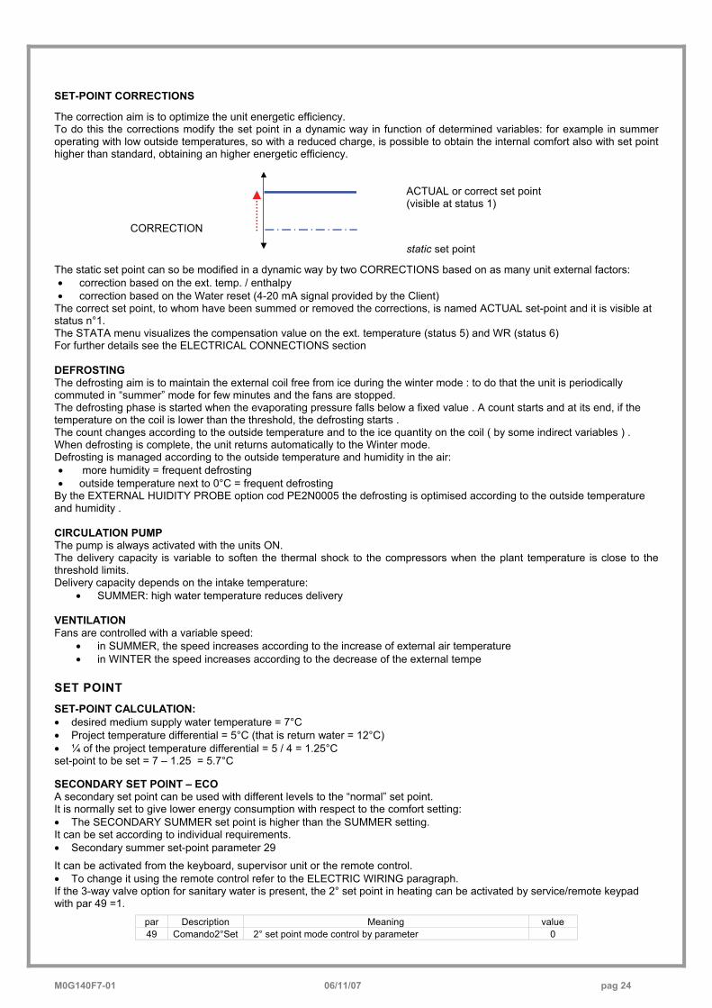
SET-POINT CORRECTIONS The correction aim is to optimize the unit energetic efficiency. To do this the corrections modify the set point in a dynamic way in function of determined variables: for example in summer operating with low outside temperatures, so with a reduced charge, is possible to obtain the internal comfort also with set point higher than standard, obtaining an higher energetic efficiency.
CORRECTION
ACTUAL or correct set point (visible at status 1) static set point
The static set point can so be modified in a dynamic way by two CORRECTIONS based on as many unit external factors: • correction based on the ext. temp. / enthalpy • correction based on the Water reset (4-20 mA signal provided by the Client)
The correct set point, to whom have been summed or removed the corrections, is named ACTUAL set-point and it is visible at status n°1. The STATA menu visualizes the compensation value on the ext. temperature (status 5) and WR (status 6) For further details see the ELECTRICAL CONNECTIONS section DEFROSTING The defrosting aim is to maintain the external coil free from ice during the winter mode : to do that the unit is periodically commuted in “summer” mode for few minutes and the fans are stopped. The defrosting phase is started when the evaporating pressure falls below a fixed value . A count starts and at its end, if the temperature on the coil is lower than the threshold, the defrosting starts . The count changes according to the outside temperature and to the ice quantity on the coil ( by some indirect variables ) . When defrosting is complete, the unit returns automatically to the Winter mode. Defrosting is managed according to the outside temperature and humidity in the air: • more humidity = frequent defrosting • outside temperature next to 0°C = frequent defrosting
By the EXTERNAL HUIDITY PROBE option cod PE2N0005 the defrosting is optimised according to the outside temperature and humidity . CIRCULATION PUMP The pump is always activated with the units ON. The delivery capacity is variable to soften the thermal shock to the compressors when the plant temperature is close to the threshold limits. Delivery capacity depends on the intake temperature:
• SUMMER: high water temperature reduces delivery VENTILATION Fans are controlled with a variable speed:
• in SUMMER, the speed increases according to the increase of external air temperature • in WINTER the speed increases according to the decrease of the external tempe
SET POINT SET-POINT CALCULATION: • desired medium supply water temperature = 7°C • Project temperature differential = 5°C (that is return water = 12°C) • ¼ of the project temperature differential = 5 / 4 = 1.25°C set-point to be set = 7 – 1.25 = 5.7°C SECONDARY SET POINT – ECO A secondary set point can be used with different levels to the “normal” set point. It is normally set to give lower energy consumption with respect to the comfort setting: • The SECONDARY SUMMER set point is higher than the SUMMER setting. It can be set according to individual requirements. • Secondary summer set-point parameter 29
It can be activated from the keyboard, supervisor unit or the remote control. • To change it using the remote control refer to the ELECTRIC WIRING paragraph. If the 3-way valve option for sanitary water is present, the 2° set point in heating can be activated by service/remote keypad with par 49 =1.
par Description Meaning value 49 Comando2°Set 2° set point mode control by parameter 0
M0G140F7-01 06/11/07 pag 25
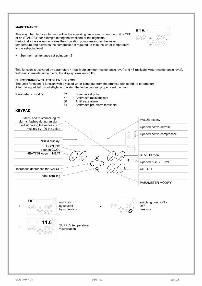
MAINTENANCE This way, the plant can be kept within the operating limits even when the unit is OFF or on STANDBY, for example during the weekend or the nighttime. Periodically the system activates the circulation pump, measures the water temperature and activates the compressor, if required, to take the water temperature to the set-point level. • Summer maintenance set-point par 42
ALARM
STATUS
SET
STB
This function is activated by parameters 44 (activate summer maintenance level) and 45 (activate winter maintenance level). With unit in maintenance mode, the display visualizes STB . FUNCTIONING WITH ETHYLENE GLYCOL The units foreseen to function with glycoled water come out from the premise with standard parameters. After having added glycol ethylene to water, the technician will properly set the plant. Parameter to modify: 32 Summer set point
77 Antifreeze resistanceset 80 Antifreeze alarm
84 Antifreeze pre-alarm threshold
KEYPAD
Menu and “historical log “of alarms flashes during an alarm VALUE display
Led signalling the necessity to multiply by 100 the value Opened active defrost
Opened active compressor
INDEX display.
COOLING open in COOL
HEATING open in HEAT STATUS menu
Opened ACTIV PUMP
Increases decreases the VALUE ON –OFF
Index scrolling
PARAMETER MODIFY
1 ALA
RM
STATUS
SET
OFF
unit in OFF. by keypad by supervisor
2 ALARM
STATUS
SET
switching: long ON - OFF pressure
3 ALARM
STATUS
SET
11.6
SUPPLY temperature visualization
ALARM
STATUS
SET
M0G140F7-01 06/11/07 pag 26
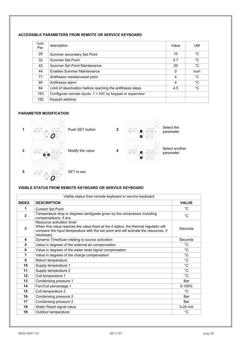
ACCESSIBLE PARAMETERS FROM REMOTE OR SERVICE KEYBOARD
num. Par. description Value UM
29 Summer secondary Set Point 10 °C
32 Summer Set Point 5.7 °C 42 Summer Set Point Maintenance 20 °C 44 Enables Summer Maintenance 0 num 77 Antifreeze resistanceset point 4 °C 80 Antifreeze alarm 4 °C 84 Limit of deactivation before reaching the antifreeze steps 4.5 °C 163 Configures remote inputs: 1 = H/C by keypad or supervisor 192 Keypad address
PARAMETER MODIFICATION
1 ALA
RM
STATUS
SET
Push SET button 2 ALA
RM
STATU
S
SET
Select the parameter
3 ALA
RM
STATU
S
SET
Modify the value 4 ALA
RM
STATUS
SET
Select another parameter
5 ALA
RM
STATU
S
SET
SET to esc
VISIBLE STATUS FROM REMOTE KEYBOARD OR SERVICE KEYBOARD
Visible status from remote keyboard or service keyboard
INDEX DESCRIPTION VALUE 1 Current Set Point °C
2 Temperature drop in degrees centigrade given by the compressor including compensations, if any °C
3 Resource activation timer When this value reaches the value fixed at the 4 status, the thermal regulator will compare the input temperature with the set point and will activate the resources, if necessary
Seconds
4 Dynamic TimeScan relating to source activation Seconds 5 Value in degrees of the external air compensation °C 6 Value in degrees of the water reset signal compensation °C 7 Value in degrees of the charge compensation °C 9 Return temperature °C
10 Supply temperature 1 °C 11 Supply temperature 2 °C 12 Coil temperature 1 °C 13 Condensing pressure 1 Bar 14 Fan/Coil percentage 1 0-100% 15 Coil temperature 2 °C 16 Condensing pressure 2 Bar 17 Condensing pressure 2 Bar 18 Water Reset signal value 4-20 mA 19 Outdoor temperature °C
M0G140F7-01 06/11/07 pag 27
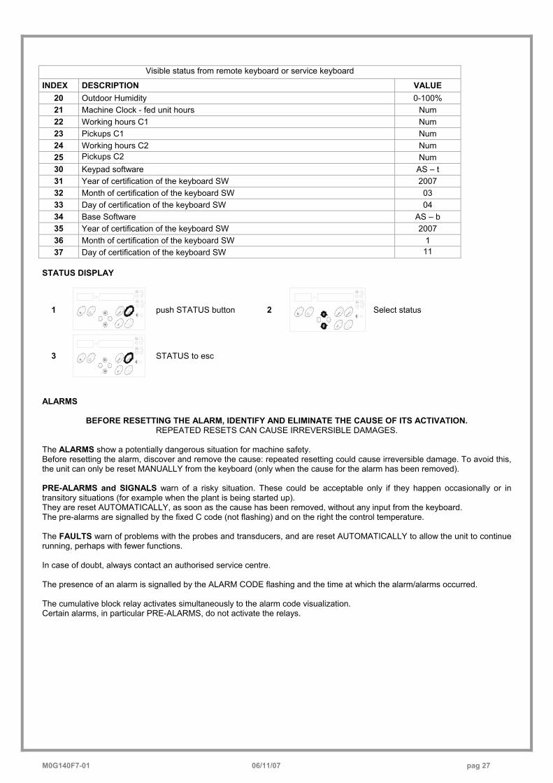
Visible status from remote keyboard or service keyboard
INDEX DESCRIPTION VALUE 20 Outdoor Humidity 0-100% 21 Machine Clock - fed unit hours Num 22 Working hours C1 Num 23 Pickups C1 Num 24 Working hours C2 Num 25 Pickups C2 Num 30 Keypad software AS – t 31 Year of certification of the keyboard SW 2007 32 Month of certification of the keyboard SW 03 33 Day of certification of the keyboard SW 04 34 Base Software AS – b 35 Year of certification of the keyboard SW 2007 36 Month of certification of the keyboard SW 1 37 Day of certification of the keyboard SW 11
STATUS DISPLAY
1 ALA
RM
STATUS
SET
push STATUS button 2 ALA
RM
STATU
S
SET
Select status
3 ALARM
STATUS
SET
STATUS to esc
ALARMS
BEFORE RESETTING THE ALARM, IDENTIFY AND ELIMINATE THE CAUSE OF ITS ACTIVATION. REPEATED RESETS CAN CAUSE IRREVERSIBLE DAMAGES.
The ALARMS show a potentially dangerous situation for machine safety. Before resetting the alarm, discover and remove the cause: repeated resetting could cause irreversible damage. To avoid this, the unit can only be reset MANUALLY from the keyboard (only when the cause for the alarm has been removed). PRE-ALARMS and SIGNALS warn of a risky situation. These could be acceptable only if they happen occasionally or in transitory situations (for example when the plant is being started up). They are reset AUTOMATICALLY, as soon as the cause has been removed, without any input from the keyboard. The pre-alarms are signalled by the fixed C code (not flashing) and on the right the control temperature. The FAULTS warn of problems with the probes and transducers, and are reset AUTOMATICALLY to allow the unit to continue running, perhaps with fewer functions. In case of doubt, always contact an authorised service centre. The presence of an alarm is signalled by the ALARM CODE flashing and the time at which the alarm/alarms occurred. The cumulative block relay activates simultaneously to the alarm code visualization. Certain alarms, in particular PRE-ALARMS, do not activate the relays.
M0G140F7-01 06/11/07 pag 28
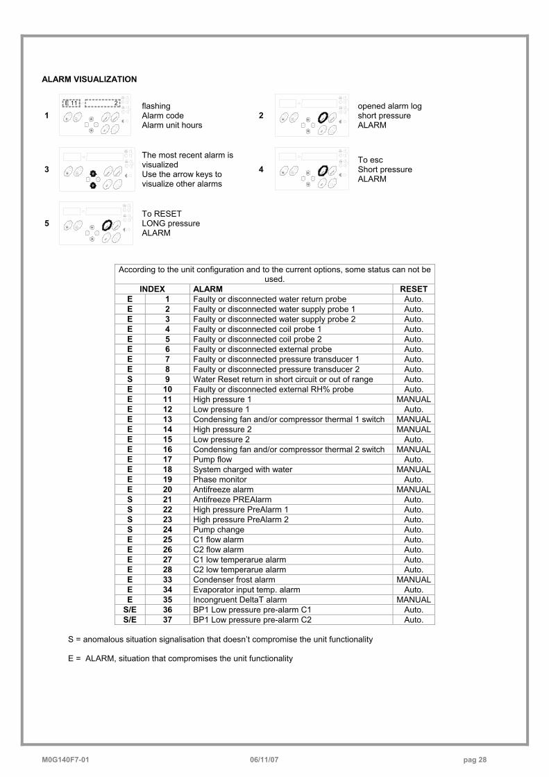
ALARM VISUALIZATION
1 ALA
RM
STATUS
SET
E 11 2
flashing Alarm code Alarm unit hours
2 ALA
RM
STATUS
SET
opened alarm log short pressure ALARM
3 ALARM
STATUS
SET
The most recent alarm is visualized Use the arrow keys to visualize other alarms
4 ALA
RM
STATUS
SET
To esc Short pressure ALARM
5 ALA
RM
STATUS
SET
To RESET LONG pressure ALARM
According to the unit configuration and to the current options, some status can not be used.
INDEX ALARM RESET E 1 Faulty or disconnected water return probe Auto. E 2 Faulty or disconnected water supply probe 1 Auto. E 3 Faulty or disconnected water supply probe 2 Auto. E 4 Faulty or disconnected coil probe 1 Auto. E 5 Faulty or disconnected coil probe 2 Auto. E 6 Faulty or disconnected external probe Auto. E 7 Faulty or disconnected pressure transducer 1 Auto. E 8 Faulty or disconnected pressure transducer 2 Auto. S 9 Water Reset return in short circuit or out of range Auto. E 10 Faulty or disconnected external RH% probe Auto. E 11 High pressure 1 MANUAL E 12 Low pressure 1 Auto. E 13 Condensing fan and/or compressor thermal 1 switch MANUAL E 14 High pressure 2 MANUAL E 15 Low pressure 2 Auto. E 16 Condensing fan and/or compressor thermal 2 switch MANUAL E 17 Pump flow Auto. E 18 System charged with water MANUAL E 19 Phase monitor Auto. E 20 Antifreeze alarm MANUAL S 21 Antifreeze PREAlarm Auto. S 22 High pressure PreAlarm 1 Auto. S 23 High pressure PreAlarm 2 Auto. S 24 Pump change Auto. E 25 C1 flow alarm Auto. E 26 C2 flow alarm Auto. E 27 C1 low temperarue alarm Auto. E 28 C2 low temperarue alarm Auto. E 33 Condenser frost alarm MANUAL E 34 Evaporator input temp. alarm Auto. E 35 Incongruent DeltaT alarm MANUAL
S/E 36 BP1 Low pressure pre-alarm C1 Auto. S/E 37 BP1 Low pressure pre-alarm C2 Auto.
S = anomalous situation signalisation that doesn’t compromise the unit functionality E = ALARM, situation that compromises the unit functionality
M0G140F7-01 06/11/07 pag 29
ROUTINE MAINTENANCE BEFORE UNDERTAKING ANY SORT OF MAINTENANCE OR CLEANING, DISCONNECT THE ELECTRICAL POWER SUPPLY TO THE UNIT, AND ENSURE THAT OTHER PEOPLE CANNOT RE-CONNECT IT . All equipment is subjected to wear out. The maintenance makes : 1. keeps the unit efficiency 2. the components last longer 3. keeps their efficiency and limits breakdowns Therefore, it is fundamental to perform periodical checks: a few controls can be performed by the user (AUTONOMOUS MAINTENANCE) and they are mainly
cleaning activities; otherwise, controls have to be performed by specialized technicians (INSPECTIONS). The machine should have a log book used to keep track of the performed controls. This will make fixing up breakdowns easier. Take note of the date, type of control (autonomous maintenance, inspection or fixing up), description of the control, actions taken and so on.
SERVICES
Parts subject to intervention: • EXTERNAL AIR COIL • WATER EXCHANGER
• STRUCTURE • ELECTRIC FANS
EXTERNAL AIR COIL ATTENTION: contact with the exchanger fins can cause cuts. Wear protective gloves to perform the above described operations. It is extremely important that the battery gives the maximum thermal exchange; therefore, its surface must be cleaned from dust and deposits. Remove all impurities from the surface. Using an air pressure gun, clean the aluminum surface of the battery. Be careful to direct the air in the opposite
direction of the fan air movement. Hold the gun parallel to the fins to avoid damages. As an alternative, an aspirator can be used to suck impurities from the air input side. Verify that the aluminum fins are not bent or damaged. In the event of damages, contact the authorized assistance center and get the battery “ironed out” in order to restore the initial condition for an optimal air flow.
WATER EXCHANGER It is very important for the exchanger to be able to provide the maximum thermal exchange. Therefore, it is essential for the inner surfaces to be clean of dirt and incrustations.
Periodically check the difference between the temperature of the supply water and the condensation temperature. If the difference is greater than 8 °C – 10 ° C it is advisable to clean the exchanger.
STRUCTURE Check the condition of the parts making up the structure. Paint so as to eliminate or reduce oxidation at the points in the unit where this problem may occur. Check that the
panelling is fastened correctly. Poor fastening may give rise to malfunctions and abnormal noise and vibration.
ELECTRIC FANS Make sure that the fans and the relative protection grids are well fixed. Check, if possible, the unbalances of the electro-fan evident by noise and anomalous vibrations. Verify that the terminal protection covers are closed and the cable holders are properly positioned.
M0G140F7-01 06/11/07 pag 30
MAINTENANCE INSPECTIONS Foresee inspection assistance carried out by authorized centers or by qualified personnel. The inspections should be carried out at least:
• - Every year for only the cooling units • - Every six months for the cooling and warming
units The frequency, however, depends on the use: in the event of frequent use (continuous or very intermittent use, near the operating limits, etc) or critical use (service necessary) it is recommended to plan inspections at close intervals. The inspections to be performed are as follows: • verify the power supply tension (when emptied or filled) • inspect the electrical board (status of solenoid starter
contacts, terminal closings, the status of wiring and relevant insulations)
• inspect the absorption of the single electrical loads • verify the cleaning and the efficiency of the exchangers • inspect the cleaning of the filters (air/water)
• verify the leakage from the refrigerating circuit • Verify the protection devices (safety valves, pressure
switches, thermostats, etc.), the adjustment systems, the control devices (alarm signalizations, probes, manometers, etc)
• check the operating parameters of the refrigerating circuit (see the following REFRIGERANT TABLES and the START-UP section)
For units equipped with safety valves, follow the Manufacturer’s instructions. Verify periodically the cleaning of the safety valves and that oxidative / corrosive phenomena are not present, in particular for installations near the sea, in industrial areas or in rooms with a corrosive atmosphere.
97/23 CE PED DIRECTIVE 97/23 CE PED DIRECTIVE gives instructions for installers, users and maintenance technicians as well. Refer to local actuation norms. In Italy, refer to the Ministerial Decree of 1st December 2004 no. 329 (and following modifications) which defines the performances to be executed; the units of 1st category and those defined by the art. 3.3 97/23/EC are not included in this regulation (see the serial number plate on the unit) .
Briefly and as an example, see the following : 1. COMPULSORY VERIFICATION OF THE FIRST
INSTALLATION only for units assembled on the installer’s building site (for ex. Condensing circuit + direct expansion unit)
2. CERTIFICATION OF SETTING IN SERVICE for all the units
3. PERIODICAL VERIFICATIONS to be executed with the frequency indicated by the Manufacturer (see the MAINTENANCE INSPECTIONS paragraph)
PUT AT REST If a long period of inactivity is foreseen, for example the winter for the cooling unit, the following is recommended:
• to turn the power off in order to avoid electrical risks or damages by lightning strike
• to avoid the risk of frosts as shown in the HYDRAULIC CONNECTIONS section, and, in particular
- to empty or add glycole in the plant sections subjected to temperatures below zero - to empty or add glycole in the water heating coils, also in summer - to power antifreeze heaters if present
If the period of inactivity is particularly long or in the event of extremely low temperatures, the external fans can be blocked temporarily; therefore, it is recommended to switch them on every month in order to avoid seizures or electrical overloads when the unit will be switched on. The restarting of the unit has to be carried out by qualified personnel, in particular, after the winter break for cooling units or when seasonal switching should be performed. When restarting, refer to the SWITCHING ON section. Schedule technical assistance in advance to avoid hitches and be able to use the installation when necessary.
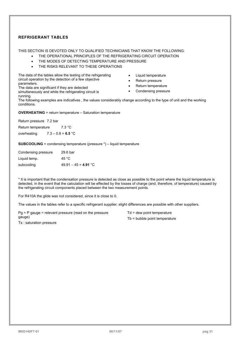
M0G140F7-01 06/11/07 pag 31
REFRIGERANT TABLES THIS SECTION IS DEVOTED ONLY TO QUALIFIED TECHNICIANS THAT KNOW THE FOLLOWING:
• THE OPERATIONAL PRINCIPLES OF THE REFRIGERATING CIRCUIT OPERATION • THE MODES OF DETECTING TEMPERATURE AND PRESSURE • THE RISKS RELEVANT TO THESE OPERATIONS
The data of the tables allow the testing of the refrigerating circuit operation by the detection of a few objective parameters. The data are significant if they are detected simultaneously and while the refrigerating circuit is running.
• Liquid temperature • Return pressure • Return temperature • Condensing pressure
The following examples are indicatives , the values considerably change according to the type of unit and the working conditions. OVERHEATING = return temperature – Saturation temperature Return pressure 7.2 bar
Return temperature 7.3 °C
overheating 7.3 – 0.8 = 6.5 °C
SUBCOOLING = condensing temperature (pressure *) – liquid temperature
Condensing pressure 29.6 bar
Liquid temp. 45 °C
subcooling 49.91 – 45 = 4.91 °C
* It is important that the condensation pressure is detected as close as possible to the point where the liquid temperature is detected, in the event that the calculation will be effected by the losses of charge (and, therefore, of temperature) caused by the refrigerating circuit components placed between the two measurement points. For R410A the glide was not considered, since it is close to 0. The values in the tables refer to a specific refrigerant supplier; slight differences are possible with other suppliers. Pg = P gauge = relevant pressure (read on the pressure gauge) Ts : saturation pressure
Td = dew point temperature Tb = bubble point temperature
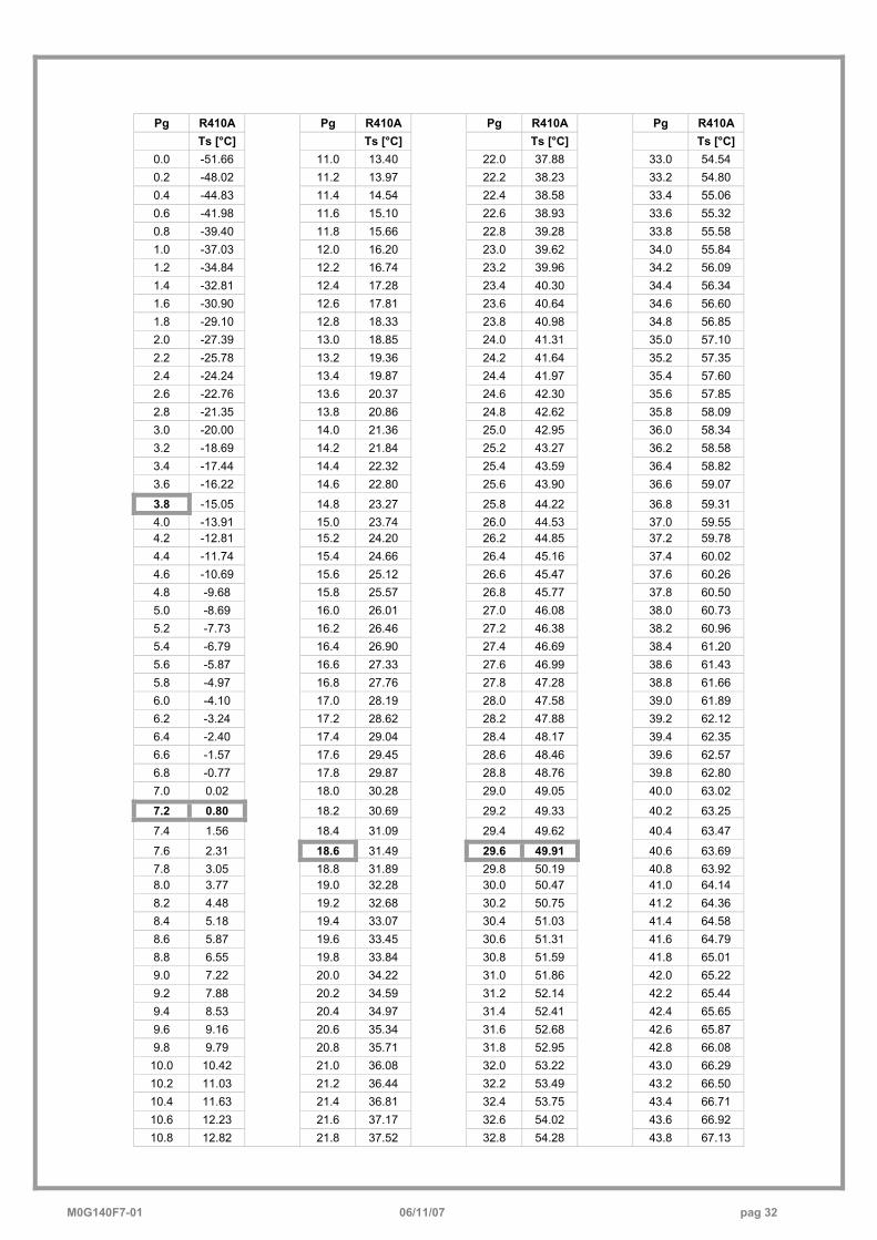
M0G140F7-01 06/11/07 pag 32
Pg R410A Pg R410A Pg R410A Pg R410A Ts [°C] Ts [°C] Ts [°C] Ts [°C]
0.0 -51.66 11.0 13.40 22.0 37.88 33.0 54.54 0.2 -48.02 11.2 13.97 22.2 38.23 33.2 54.80 0.4 -44.83 11.4 14.54 22.4 38.58 33.4 55.06 0.6 -41.98 11.6 15.10 22.6 38.93 33.6 55.32 0.8 -39.40 11.8 15.66 22.8 39.28 33.8 55.58 1.0 -37.03 12.0 16.20 23.0 39.62 34.0 55.84 1.2 -34.84 12.2 16.74 23.2 39.96 34.2 56.09 1.4 -32.81 12.4 17.28 23.4 40.30 34.4 56.34 1.6 -30.90 12.6 17.81 23.6 40.64 34.6 56.60 1.8 -29.10 12.8 18.33 23.8 40.98 34.8 56.85 2.0 -27.39 13.0 18.85 24.0 41.31 35.0 57.10 2.2 -25.78 13.2 19.36 24.2 41.64 35.2 57.35 2.4 -24.24 13.4 19.87 24.4 41.97 35.4 57.60 2.6 -22.76 13.6 20.37 24.6 42.30 35.6 57.85 2.8 -21.35 13.8 20.86 24.8 42.62 35.8 58.09 3.0 -20.00 14.0 21.36 25.0 42.95 36.0 58.34 3.2 -18.69 14.2 21.84 25.2 43.27 36.2 58.58 3.4 -17.44 14.4 22.32 25.4 43.59 36.4 58.82 3.6 -16.22 14.6 22.80 25.6 43.90 36.6 59.07
3.8 -15.05 14.8 23.27 25.8 44.22 36.8 59.31 4.0 -13.91 15.0 23.74 26.0 44.53 37.0 59.55 4.2 -12.81 15.2 24.20 26.2 44.85 37.2 59.78 4.4 -11.74 15.4 24.66 26.4 45.16 37.4 60.02 4.6 -10.69 15.6 25.12 26.6 45.47 37.6 60.26 4.8 -9.68 15.8 25.57 26.8 45.77 37.8 60.50 5.0 -8.69 16.0 26.01 27.0 46.08 38.0 60.73 5.2 -7.73 16.2 26.46 27.2 46.38 38.2 60.96 5.4 -6.79 16.4 26.90 27.4 46.69 38.4 61.20 5.6 -5.87 16.6 27.33 27.6 46.99 38.6 61.43 5.8 -4.97 16.8 27.76 27.8 47.28 38.8 61.66 6.0 -4.10 17.0 28.19 28.0 47.58 39.0 61.89 6.2 -3.24 17.2 28.62 28.2 47.88 39.2 62.12 6.4 -2.40 17.4 29.04 28.4 48.17 39.4 62.35 6.6 -1.57 17.6 29.45 28.6 48.46 39.6 62.57 6.8 -0.77 17.8 29.87 28.8 48.76 39.8 62.80 7.0 0.02 18.0 30.28 29.0 49.05 40.0 63.02
7.2 0.80 18.2 30.69 29.2 49.33 40.2 63.25
7.4 1.56 18.4 31.09 29.4 49.62 40.4 63.47
7.6 2.31 18.6 31.49 29.6 49.91 40.6 63.69 7.8 3.05 18.8 31.89 29.8 50.19 40.8 63.92 8.0 3.77 19.0 32.28 30.0 50.47 41.0 64.14 8.2 4.48 19.2 32.68 30.2 50.75 41.2 64.36 8.4 5.18 19.4 33.07 30.4 51.03 41.4 64.58 8.6 5.87 19.6 33.45 30.6 51.31 41.6 64.79 8.8 6.55 19.8 33.84 30.8 51.59 41.8 65.01 9.0 7.22 20.0 34.22 31.0 51.86 42.0 65.22 9.2 7.88 20.2 34.59 31.2 52.14 42.2 65.44 9.4 8.53 20.4 34.97 31.4 52.41 42.4 65.65 9.6 9.16 20.6 35.34 31.6 52.68 42.6 65.87 9.8 9.79 20.8 35.71 31.8 52.95 42.8 66.08
10.0 10.42 21.0 36.08 32.0 53.22 43.0 66.29 10.2 11.03 21.2 36.44 32.2 53.49 43.2 66.50 10.4 11.63 21.4 36.81 32.4 53.75 43.4 66.71 10.6 12.23 21.6 37.17 32.6 54.02 43.6 66.92 10.8 12.82
21.8 37.52
32.8 54.28
43.8 67.13
M0G140F7-01 06/11/07 pag 33
TROUBLESHOOTING
THE OPERATIONS MUST BE CARRIED OUT BY TECHNICAL QUALIFIED PERSONNEL HAVING THE REQUISITES UNDER LAW REQUISITES AND IN CONFORMITY WITH THE SAFETY REGULATIONS IN FORCE. THE INTERVENTIONS WITHIN THE WARRANTY PERIOD WILL BE CARRIED OUT BY AUTHORIZED SERVICE CENTERS. BEFORE RESETTING AN ALARM, IDENTIFY AND ELIMINATE ITS CAUSE. REPEATED RESETS MAY CAUSE SERIOUS DAMAGES. In certain machine configurations, some safeties may be placed in series and lead back to a single input on the electronic module. Therefore, check on the electrical diagram whether the device to which the alarm corresponds has other devices or safeties
connected in series. Below is a list of the possible causes of alarms. HIGH PRESSURE (in cooling) 1. high water temperature (see operating limits) 2. high air temperature (see operating limits) 3. coil dirty / clogged 4. fans don’t work / low speed 5. Manostat/transducer: loose electric contacts/terminals,
wiring cables interrupted 6. Anti-condensation gas in the cooling circuit 7. Too much refrigerant 8. Check the trigger point for the manostat and
transducer 9. Check the manostat or transducer pressure control
point (deposits of oil, dirt, pin blocked mechanically)
LOW PRESSURE (in cooling) 1. low air temperature (see operating limits) 2. low water temperature (see operating limits) 3. insufficient water flow to the exchanger (high thermal
difference between input and output) 4. not CONSTANT flow (for example, if the pumps are
turned off, certain areas of the plant are excluded or included, other uses are isolated, etc )
5. Water filter clean / valves open /air bubbles in the plant
6. dirty exchanger 7. Manostat/transducer: loose electric
contacts/terminals, wiring cables interrupted 8. refrigerant circuit empty, visible leaks of refrigerant/oil,
insufficient charge 9. Blocked dehydrator filter
10. thermostatic device not operating correctly 11. Check the trigger point for the manostat and
transducer 12. Check the manostat or transducer pressure control
point (deposits of oil, dirt, pin blocked mechanically)
FAULTY PROBE 1. Identify the part on the wiring diagram. 2. Loose electric contacts/terminals, leads broken 3. Check the correct probe ohmic level (using a
tester) 4. Change the probe. 5. Check the electronic module configuration (only an
authorised service centre can do this) 6. Change the electronic module
FAULTY PRESSURE TRANSDUCER
1. Identify the part on the wiring diagram 2. Loose electric contacts/terminals, leads broken 3. Check the pressure test points are in working
order 4. Change the part 5. Check the electronic module configuration (only an
authorised service centre can do this) 6. Change the electronic module
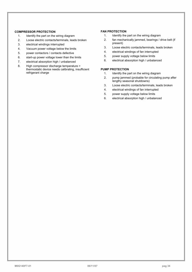
M0G140F7-01 06/11/07 pag 34
COMPRESSOR PROTECTION
1. Identify the part on the wiring diagram 2. Loose electric contacts/terminals, leads broken 3. electrical windings interrupted 4. Vacuum power voltage below the limits 5. power contactors / contacts defective 6. start-up power voltage lower than the limits 7. electrical absorption high / unbalanced 8. High compressor discharge temperature >
thermostatic device needs calibrating, insufficient refrigerant charge
FAN PROTECTION 1. Identify the part on the wiring diagram 2. fan mechanically jammed, bearings / drive belt (if
present) 3. Loose electric contacts/terminals, leads broken 4. electrical windings of fan interrupted 5. power supply voltage below limits 6. electrical absorption high / unbalanced
PUMP PROTECTION
1. Identify the part on the wiring diagram 2. pump jammed (probable for circulating pump after
lengthy seasonal shutdowns) 3. Loose electric contacts/terminals, leads broken 4. electrical windings of fan interrupted 5. power supply voltage below limits 6. electrical absorption high / unbalanced
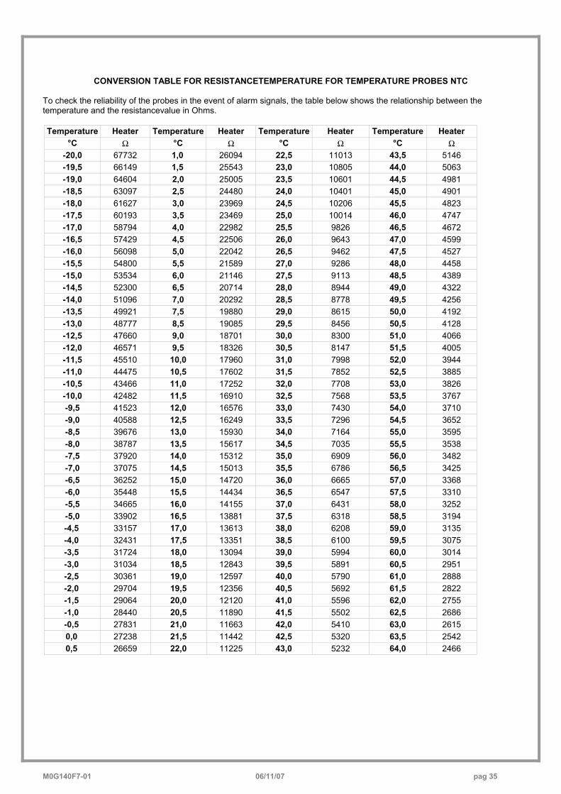
M0G140F7-01 06/11/07 pag 35
CONVERSION TABLE FOR RESISTANCETEMPERATURE FOR TEMPERATURE PROBES NTC
To check the reliability of the probes in the event of alarm signals, the table below shows the relationship between the temperature and the resistancevalue in Ohms. Temperature Heater Temperature Heater Temperature Heater Temperature Heater
°C Ω °C Ω °C Ω °C Ω -20,0 67732 1,0 26094 22,5 11013 43,5 5146 -19,5 66149 1,5 25543 23,0 10805 44,0 5063 -19,0 64604 2,0 25005 23,5 10601 44,5 4981 -18,5 63097 2,5 24480 24,0 10401 45,0 4901 -18,0 61627 3,0 23969 24,5 10206 45,5 4823 -17,5 60193 3,5 23469 25,0 10014 46,0 4747 -17,0 58794 4,0 22982 25,5 9826 46,5 4672 -16,5 57429 4,5 22506 26,0 9643 47,0 4599 -16,0 56098 5,0 22042 26,5 9462 47,5 4527 -15,5 54800 5,5 21589 27,0 9286 48,0 4458 -15,0 53534 6,0 21146 27,5 9113 48,5 4389 -14,5 52300 6,5 20714 28,0 8944 49,0 4322 -14,0 51096 7,0 20292 28,5 8778 49,5 4256 -13,5 49921 7,5 19880 29,0 8615 50,0 4192 -13,0 48777 8,5 19085 29,5 8456 50,5 4128 -12,5 47660 9,0 18701 30,0 8300 51,0 4066 -12,0 46571 9,5 18326 30,5 8147 51,5 4005 -11,5 45510 10,0 17960 31,0 7998 52,0 3944 -11,0 44475 10,5 17602 31,5 7852 52,5 3885 -10,5 43466 11,0 17252 32,0 7708 53,0 3826 -10,0 42482 11,5 16910 32,5 7568 53,5 3767 -9,5 41523 12,0 16576 33,0 7430 54,0 3710 -9,0 40588 12,5 16249 33,5 7296 54,5 3652 -8,5 39676 13,0 15930 34,0 7164 55,0 3595 -8,0 38787 13,5 15617 34,5 7035 55,5 3538 -7,5 37920 14,0 15312 35,0 6909 56,0 3482 -7,0 37075 14,5 15013 35,5 6786 56,5 3425 -6,5 36252 15,0 14720 36,0 6665 57,0 3368 -6,0 35448 15,5 14434 36,5 6547 57,5 3310 -5,5 34665 16,0 14155 37,0 6431 58,0 3252 -5,0 33902 16,5 13881 37,5 6318 58,5 3194 -4,5 33157 17,0 13613 38,0 6208 59,0 3135 -4,0 32431 17,5 13351 38,5 6100 59,5 3075 -3,5 31724 18,0 13094 39,0 5994 60,0 3014 -3,0 31034 18,5 12843 39,5 5891 60,5 2951 -2,5 30361 19,0 12597 40,0 5790 61,0 2888 -2,0 29704 19,5 12356 40,5 5692 61,5 2822 -1,5 29064 20,0 12120 41,0 5596 62,0 2755 -1,0 28440 20,5 11890 41,5 5502 62,5 2686 -0,5 27831 21,0 11663 42,0 5410 63,0 2615 0,0 27238 21,5 11442 42,5 5320 63,5 2542 0,5 26659 22,0 11225 43,0 5232 64,0 2466
M0G140F7-01 06/11/07 pag 36
DECOMMISSIONING OF THE UNIT
DISCONNECTING THE UNIT The units must be disconnected by authorised personnel, who before proceeding must first read the Residual Risks section in this manual. Before disconnecting the unit, the following must be recovered, if present:
• the refrigerant (if the circuits cannot be isolated): the refrigerant must be removed using suction devices operating in a closed circuit, so as to ensure that none of the compound is released into the atmosphere.
• the antifreeze in the circuits: when removing this fluid, make sure that it does not leak and that it is not released into the environment. The antifreeze fluid must be stored in special containers.
When recovering the substances present in the unit, all measures must be taken to avoid damaging persons and things and polluting the surrounding area. Awaiting dismantling and disposal, the unit can also be stored outdoors, as bad weather and rapid changes in temperature will not cause damage to the environment, if electric, cooling and hydraulic circuits of the unit are integral and closed.
DISMANTLING AND DISPOSAL THE UNIT MUST ALWAYS BE SENT TO AUTHORISED CENTRES FOR DISMANTLING AND DISPOSAL. When dismantling the unit, the fan, the motor and the coil, if operating, may be recovered by the specialist centres for reuse. All the materials must be recovered or disposed of in compliance with the corresponding national standards in force. For further information on the decommissioning of the unit, contact the manufacturer.
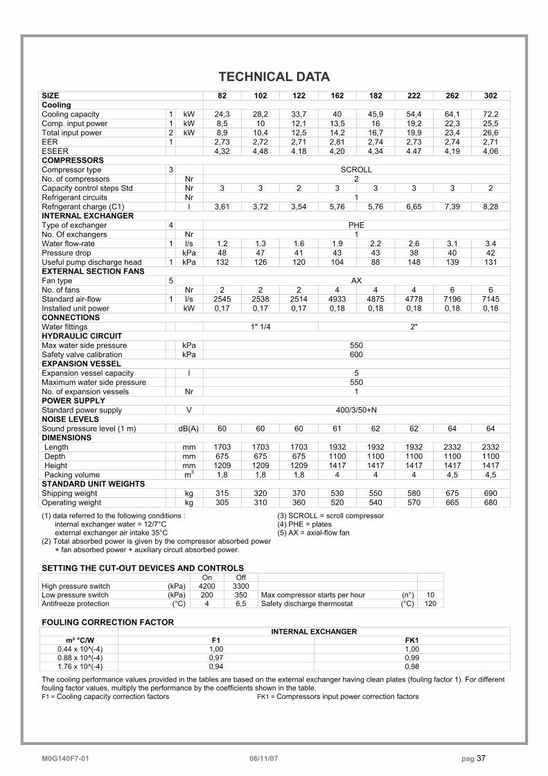
M0G140F7-01 06/11/07 pag 37
TECHNICAL DATA
SIZE 82 102 122 162 182 222 262 302 Cooling Cooling capacity 1 kW 24,3 28,2 33,7 40 45,9 54,4 64,1 72,2 Comp. input power 1 kW 8,5 10 12,1 13,5 16 19,2 22,3 25,5 Total input power 2 kW 8,9 10,4 12,5 14,2 16,7 19,9 23,4 26,6 EER 1 2,73 2,72 2,71 2,81 2,74 2,73 2,74 2,71 ESEER 4,32 4,48 4.18 4,20 4,34 4.47 4,19 4,06 COMPRESSORS Compressor type 3 SCROLL No. of compressors Nr 2 Capacity control steps Std Nr 3 3 2 3 3 3 3 2 Refrigerant circuits Nr 1 Refrigerant charge (C1) l 3,61 3,72 3,54 5,76 5,76 6,65 7,39 8,28 INTERNAL EXCHANGER Type of exchanger 4 PHE No. Of exchangers Nr 1 Water flow-rate 1 l/s 1.2 1.3 1.6 1.9 2.2 2.6 3.1 3.4 Pressure drop kPa 48 47 41 43 43 38 40 42 Useful pump discharge head 1 kPa 132 126 120 104 88 148 139 131 EXTERNAL SECTION FANS Fan type 5 AX No. of fans Nr 2 2 2 4 4 4 6 6 Standard air-flow 1 l/s 2545 2538 2514 4933 4875 4778 7196 7145 Installed unit power kW 0,17 0,17 0,17 0,18 0,18 0,18 0,18 0,18 CONNECTIONS Water fittings 1" 1/4 2" HYDRAULIC CIRCUIT Max water side pressure kPa 550 Safety valve calibration kPa 600 EXPANSION VESSEL Expansion vessel capacity l 5 Maximum water side pressure 550 No. of expansion vessels Nr 1 POWER SUPPLY Standard power supply V 400/3/50+N NOISE LEVELS Sound pressure level (1 m) dB(A) 60 60 60 61 62 62 64 64 DIMENSIONS Length mm 1703 1703 1703 1932 1932 1932 2332 2332 Depth mm 675 675 675 1100 1100 1100 1100 1100 Height mm 1209 1209 1209 1417 1417 1417 1417 1417 Packing volume m3 1,8 1,8 1,8 4 4 4 4,5 4,5
STANDARD UNIT WEIGHTS Shipping weight kg 315 320 370 530 550 580 675 690 Operating weight kg 305 310 360 520 540 570 665 680
(1) data referred to the following conditions : internal exchanger water = 12/7°C external exchanger air intake 35°C
(2) Total absorbed power is given by the compressor absorbed power + fan absorbed power + auxiliary circuit absorbed power.
(3) SCROLL = scroll compressor (4) PHE = plates (5) AX = axial-flow fan
SETTING THE CUT-OUT DEVICES AND CONTROLS On Off High pressure switch (kPa) 4200 3300 Low pressure switch (kPa) 200 350 Max compressor starts per hour (n°) 10 Antifreeze protection (°C) 4 6,5 Safety discharge thermostat (°C) 120 FOULING CORRECTION FACTOR INTERNAL EXCHANGER
m² °C/W F1 FK1 0.44 x 10^(-4) 1,00 1,00 0.88 x 10^(-4) 0,97 0,99 1.76 x 10^(-4) 0,94 0,98
The cooling performance values provided in the tables are based on the external exchanger having clean plates (fouling factor 1). For different fouling factor values, multiply the performance by the coefficients shown in the table. F1 = Cooling capacity correction factors FK1 = Compressors input power correction factors
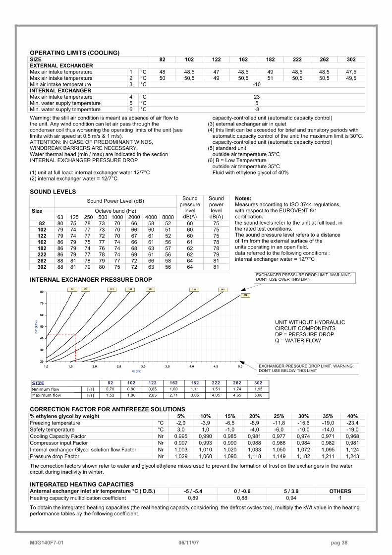
M0G140F7-01 06/11/07 pag 38
OPERATING LIMITS (COOLING) SIZE 82 102 122 162 182 222 262 302 EXTERNAL EXCHANGER Max air intake temperature 1 °C 48 48,5 47 48,5 49 48,5 48,5 47,5 Max air intake temperature 2 °C 50 50,5 49 50,5 51 50,5 50,5 49,5 Min air intake temperature 3 °C -10 INTERNAL EXCHANGER Max air intake temperature 4 °C 23 Min. water supply temperature 5 °C 5 Min. water supply temperature 6 °C -8
Warning: the still air condition is meant as absence of air flow to the unit. Any wind condition can let air pass through the condenser coil thus worsening the operating limits of the unit (see limits with air speed at 0,5 m/s & 1 m/s). ATTENTION: IN CASE OF PREDOMINANT WINDS, WINDBREAK BARRIERS ARE NECESSARY. Water thermal head (min / max) are indicated in the section INTERNAL EXCHANGER PRESSURE DROP (1) unit at full load: internal exchanger water 12/7°C (2) internal exchanger water = 12/7°C
capacity-controlled unit (automatic capacity control) (3) external exchanger air in quiet (4) this limit can be exceeded for brief and transitory periods with
automatic capacity control of the unit: the maximum limit is 30°C. capacity-controlled unit (automatic capacity control)
(5) standard unit outside air temperature 35°C
(6) B = Low Temperature outside air temperature 35°C Fluid with ethylene glycol of 40%
SOUND LEVELS
Sound Power Level (dB)
Size Octave band (Hz) 63 125 250 500 1000 2000 4000 8000
Sound pressure
level dB(A)
Sound power level dB(A)
82 80 75 78 73 70 66 58 52 60 75 102 79 74 77 73 70 66 60 51 60 75 122 79 74 77 72 70 67 61 52 60 75 162 86 79 75 77 74 66 61 56 61 78 182 86 79 74 76 74 68 63 57 62 78 222 86 79 77 78 74 69 61 56 62 79 262 88 81 78 79 77 72 66 58 64 81 302 88 81 79 80 75 72 63 56 64 81
Notes: Measures according to ISO 3744 regulations, with respect to the EUROVENT 8/1 certification. the sound levels refer to the unit at full load, in the rated test conditions. The sound pressure level refers to a distance of 1m from the external surface of the units operating in an open field. data referred to the following conditions : internal exchanger water = 12/7°C
INTERNAL EXCHANGER PRESSURE DROP
20
30
40
50
60
70
80
1,0 1,5 2,0 2,5 3,0 3,5 4,0 4,5 5,0Q (l/s)
DP
(kP
a)
22282
30261
122102 26261
182162
UNIT WITHOUT HYDRAULIC CIRCUIT COMPONENTS DP = PRESSURE DROP Q = WATER FLOW
GRANDEZZA 82 102 122 162 182 222 262 302Portata minima [l/s] 0,70 0,80 0,85 1,00 1,11 1,51 1,74 1,95Portata massima [l/s] 1,52 1,80 2,85 2,71 3,05 4,05 4,65 5,00
CORRECTION FACTOR FOR ANTIFREEZE SOLUTIONS % ethylene glycol by weight 5% 10% 15% 20% 25% 30% 35% 40% Freezing temperature °C -2,0 -3,9 -6,5 -8,9 -11,8 -15,6 -19,0 -23,4 Safety temperature °C 3,0 1,0 -1,0 -4,0 -6,0 -10,0 -14,0 -19,0 Cooling Capacity Factor Nr 0,995 0,990 0,985 0,981 0,977 0,974 0,971 0,968 Compressor input Factor Nr 0,997 0,993 0,990 0,988 0,986 0,984 0,982 0,981 Internal exchanger Glycol solution flow Factor Nr 1,003 1,010 1,020 1,033 1,050 1,072 1,095 1,124 Pressure drop Factor Nr 1,029 1,060 1,090 1,118 1,149 1,182 1,211 1,243
The correction factors shown refer to water and glycol ethylene mixes used to prevent the formation of frost on the exchangers in the water circuit during inactivity in winter. INTEGRATED HEATING CAPACITIES Anternal exchanger inlet air temperature °C ( D.B.) -5 / -5.4 0 / -0.6 5 / 3.9 OTHERS Heating capacity multiplication coefficient 0,89 0,88 0,94 1
To obtain the integrated heating capacities (the real heating capacity considering the defrost cycles too), multiply the kWt value in the heating performance tables by the following coefficient.
EXCHANGER PRESSURE DROP LIMIT. WAR-NING:DON'T USE OVER THIS LIMIT
EXCHAMGER PRESSURE DROP LIMIT. WARNING: DON'T USE BELOW THIS LIMIT
Minimum flow Maximum flow
SIZE
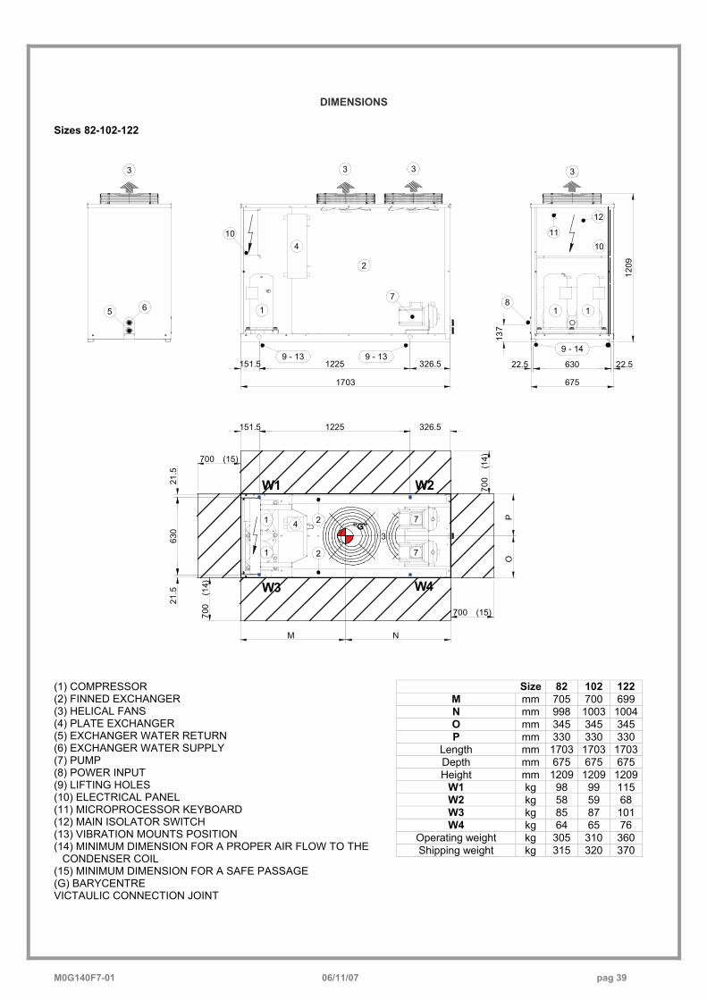
M0G140F7-01 06/11/07 pag 39
DIMENSIONS
Sizes 82-102-122
1225 22.5 630 22.5
675
137
1209
11
12
10
1 11
104
4
3333
5 6
7
7
3
1
1
2
2
2
7
9 - 13 9 - 13
700
(14)
700 (15)
700
(14)
700 (15)
8
M N
OP
W1 W2
W4W3
151.5 326.5
1703
9 - 14
151.5 1225 326.5
21.5
630
21.5
"G"
Size 82 102 122 M mm 705 700 699 N mm 998 1003 1004O mm 345 345 345 P mm 330 330 330
Length mm 1703 1703 1703Depth mm 675 675 675 Height mm 1209 1209 1209
W1 kg 98 99 115 W2 kg 58 59 68 W3 kg 85 87 101 W4 kg 64 65 76
Operating weight kg 305 310 360 Shipping weight kg 315 320 370
(1) COMPRESSOR (2) FINNED EXCHANGER (3) HELICAL FANS (4) PLATE EXCHANGER (5) EXCHANGER WATER RETURN (6) EXCHANGER WATER SUPPLY (7) PUMP (8) POWER INPUT (9) LIFTING HOLES (10) ELECTRICAL PANEL (11) MICROPROCESSOR KEYBOARD (12) MAIN ISOLATOR SWITCH (13) VIBRATION MOUNTS POSITION (14) MINIMUM DIMENSION FOR A PROPER AIR FLOW TO THE
CONDENSER COIL (15) MINIMUM DIMENSION FOR A SAFE PASSAGE (G) BARYCENTRE VICTAULIC CONNECTION JOINT
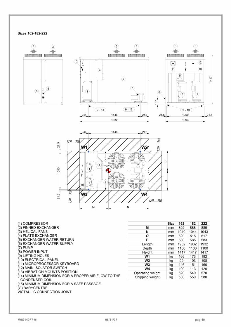
M0G140F7-01 06/11/07 pag 40
Sizes 162-182-222
3
56
3 33
4
1
5
1 1
10
7
7
3
3
41
110
2
10
2
9 - 13
33
11
12
7
9 - 13 9 - 13
W1 W2
W4W3
1417
21.5105021.5
10931932
2421446244
137
2
M N
OP
700
(14)
700 (15)
700
(14)700 (15)
8
1050
21.5
21.5
1446244 242
"G"
Size 162 182 222 M mm 892 888 889 N mm 1040 1044 1043O mm 520 515 517 P mm 580 585 583
Length mm 1932 1932 1932Depth mm 1100 1100 1100Height mm 1417 1417 1417
W1 kg 166 173 182 W2 kg 99 103 108 W3 kg 146 151 160 W4 kg 109 113 120
Operating weight kg 520 540 570 Shipping weight kg 530 550 580
(1) COMPRESSOR (2) FINNED EXCHANGER (3) HELICAL FANS (4) PLATE EXCHANGER (5) EXCHANGER WATER RETURN (6) EXCHANGER WATER SUPPLY (7) PUMP (8) POWER INPUT (9) LIFTING HOLES (10) ELECTRICAL PANEL (11) MICROPROCESSOR KEYBOARD (12) MAIN ISOLATOR SWITCH (13) VIBRATION MOUNTS POSITION (14) MINIMUM DIMENSION FOR A PROPER AIR FLOW TO THE
CONDENSER COIL (15) MINIMUM DIMENSION FOR A SAFE PASSAGE (G) BARYCENTRE VICTAULIC CONNECTION JOINT
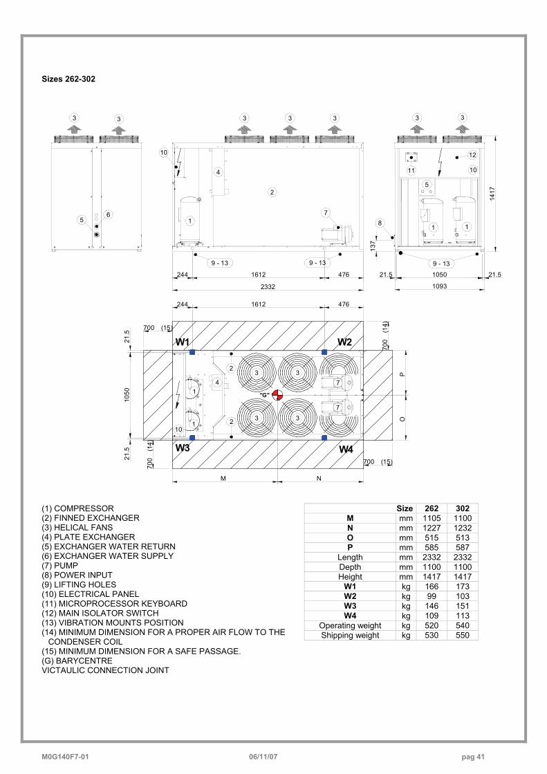
M0G140F7-01 06/11/07 pag 41
Sizes 262-302
3
56
3 33
4
1
5
1 1
10
7
7
3
3
41
110
2
10
2
9 - 13
33
11
12
7
9 - 13 9 - 13
W1 W2
W4W3
1417
21.5105021.5
10932332
4761612244
137
2
M N
OP
700
(14)
700 (15)
700
(14)700 (15)
8
3
3
3
"G"
1050
21.5
21.5
244 1612 476
Size 262 302 M mm 1105 1100 N mm 1227 1232 O mm 515 513 P mm 585 587
Length mm 2332 2332 Depth mm 1100 1100 Height mm 1417 1417
W1 kg 166 173 W2 kg 99 103 W3 kg 146 151 W4 kg 109 113
Operating weight kg 520 540 Shipping weight kg 530 550
(1) COMPRESSOR (2) FINNED EXCHANGER (3) HELICAL FANS (4) PLATE EXCHANGER (5) EXCHANGER WATER RETURN (6) EXCHANGER WATER SUPPLY (7) PUMP (8) POWER INPUT (9) LIFTING HOLES (10) ELECTRICAL PANEL (11) MICROPROCESSOR KEYBOARD (12) MAIN ISOLATOR SWITCH (13) VIBRATION MOUNTS POSITION (14) MINIMUM DIMENSION FOR A PROPER AIR FLOW TO THE
CONDENSER COIL (15) MINIMUM DIMENSION FOR A SAFE PASSAGE. (G) BARYCENTRE VICTAULIC CONNECTION JOINT


CLIVET SPAFeltre (BL) ITALYTel. + 39 0439 3131Fax + 39 0439 [email protected]
CLIVET ESPAÑA S.A.Madrid - SPAINTel. + 34 91 6658280Fax + 34 91 [email protected]
CLIVET UK LTDFareham (Hampshire) U.K.Tel. + 44 (0) 1489 572238Fax + 44 (0) 1489 [email protected]
CLIVET NEDERLAND B.V.Amersfoort - NetherlandsTel. + 31 (0) 33 7503420Fax + 31 (0) 33 [email protected]
CLIVET TFAIR SYSTEMS (P)LTD.Malur - INDIATel. +91 8151 232683/5Fax [email protected]
CLIVET SPABUREAU DE LIAISON EN FRANCEVerrierès le Buisson - FRANCETel. + 33 (0)1 69 20 25 75Fax + 33 (0)1 69 20 60 [email protected]
CLIVET GmbHNorderstedt - GERMANYTel. +49 (0) 40 32 59 57-0Fax +49 (0) 40 32 59 [email protected]
The data contained in this bulletin is not binding and may be changed by the manufacturer without prior notice. All reproduction, even
partial, is PROHIBITED.
© COPYRIGHT - CLIVET S.P.A. - FELTRE (BL) - ITALIA


![Xee Boarding Pass Front Art.indd 1 17/4/08 1:15:52 PMevangelismexplosion.org/wp-content/uploads/XEE-eBoardingPass.pdfIgV^c^c\ =VcYWdd` [dg Wdi] HijYZcih VcY ;VX^a^iVidg IgV^c^c\ 9K9](https://img.pdfslide.us/doc/110x75/5ae0b1057f8b9a6e5c8dc176/xee-boarding-pass-front-artindd-1-17408-11552-p-cc-vcywdd-dg-wdi-hijyzcih.jpg)