Embed Size (px)
Citation preview
8/6/2019 Ws2x20 Pc En
http://slidepdf.com/reader/full/ws2x20-pc-en 1/4
Working StandardMultifunction hand-held Working Standard of power and energy for on site meter testing
Applied Precision Ltd.Stavitelska 1, 83104 Bratislava, Slovakia
Fax:+421 2 3266 2300, Tel: +421 2 3266 2301Web: www.appliedp.com, E-mail: [email protected]
Highlights
• Lightweight compact size
• Single-phase and three-phase versions, accuracy classes 0.2, 0.1, 0.05
• Color graphic display and alphanumerical keypad
• USB, RS-232 and optical interface for local data exchange with multi-
functional meters according to IEC 62056-21• Configuration and data stored in high capacity memory (min. 2 GB)
• Vector diagram and signal shape display (oscilloscope mode)
• Harmonics analysis in tabular and graphical format
• Two universal input channels for any combination of Voltage and Currentprobes for Power or CT / VT ratio, phase and burden measurement
• LED and TTL impulse outputs with programmable energy proportionalmeter constant or programmable frequency
• Enhanced internal database system for tested meters and measured resultswith search capabilities
• Enhanced self-adjusting optical scanning head
• Synchronous differential energy consumption measurement
• Optional wireless communication interface and wireless scanning headnetwork for simultaneous testing of multiple delivery nodes
• Enhanced fast synchronization of measured data and configuration with PC
• PC software for MS Windows
• Transport case with high protection degree
• Optional portable printer for printing of results and actual display content
• Optional universal isolated input/output (relay, logic signal)
• Configurable user interface (regional and functional modifications)
Description
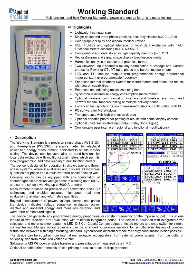
The Working Standard is a precision single-phase (WS 2120)and three-phase (WS 2320) reference meter for electricalpower and energy measurement, dedicated to on-site meterstesting. The device can be used also as hand-held unit forlocal data exchange with multifunctional meters which permitslocal programming and data reading of multifunction meters.
The device is designed for operation in single-, two- and three-phase systems, where it evaluates and displays all individualquantities per phase and cumulative three-phase ones as well.
Universal inputs can be equipped with any combination ofinterchangeable precision voltage sensors working up to 500 Vand current sensors working up to 6000 A or more.
Measurement is based on precision A/D conversion and DSP
technology and enables accurate high-speed real timeevaluation of all main and informative quantities.
Beyond measurement of power, voltage, current and phasethe device indicates voltage sequence, evaluates active,reactive and apparent energy and measures distortion andwave-form of measured signals.
The device can generate any programmed energy proportional or constant frequency on the impulse output. This uniquefeature allows precision error evaluation with minimum integration period. The device is equipped with integrated errorcalculator and meter scanner capturing LED, DISK or Closed Contact output of tested meters and snap switch for simplemanual testing. Multiple optical scanners can be arranged to wireless network for simultaneous testing of complexdistribution networks with single Working Standard. Synchronous differential mode of energy consumption is also possible.
The device can be supplied from internal rechargeable accumulators, from external power adapter, from car outlet or
optionally also from measured voltage circuit.Software for MS Windows enables transfer and presentation of measured data in PC.
Optional portable printer enables on-site printing of results or actual display content.

8/6/2019 Ws2x20 Pc En
http://slidepdf.com/reader/full/ws2x20-pc-en 2/4
Working StandardMultifunction hand-held Working Standard of power and energy for on site meter testing
The information in this document is subject to change without notice WS-PC201101-EN
Technical Specification
Basic Error*1
WS 2120AWS 2320A
WS 2120BWS 2320B
WS 2120CWS 2320C
Current dependent on type of current sensor
Voltage 0.05 % 0.1 % 0.2 %
Apparent Power 0.05 % 0.1 % 0.2 %Active Power
*2 0.05 % 0.1 % 0.2 %
Reactive Power*2
0.05 % 0.1 % 0.2 %
Power Factor 0.001 0.002 0.004
Frequency 0.01 Hz 0.01 Hz 0.01 Hz
Distortion 0.2 % 0.5 % 0.5 %
Phase Angle 0.01 ° 0.03 ° 0.1 °
Measured Quantities
Voltage, Current; Active, Reactive and Apparent Power; Active, Reactive andApparent Energy, Power Factor, Phase Angle, Frequency, Distortion; ActivePower of Harmonics; Burden, phase and transformation ratio of current andvoltage transformers
General Specifications
Basic Frequency 40 .. 70 Hz
Input Circuits1-phase 2-wire (WS 2120 & WS 2320) 1-phase 3-wire and 2-phase (WS 2320)
3-phase 3-wire / 4-wire (WS 2320)
Voltage Range 0.1 .. 500 V phase to neutral manualor auto
range Current Rangedepending on type of current sensor - up to20 A / 120 A / 240 A / 6000 A (or more)
Power Factor Range -1 .. 0 .. 1
Phase Angle 0 .. 360 °
Communication
USB and RS-232 interfaces,optical interface for communication with metersaccording to IEC 62056-21 (via OPTH 1200),optionally wireless (2.4 GHz)
Display 3.5” / 320 x 240 pixels / 256 colors
Memory for Data min. 2 GB ( >1000 load points )
Oper. Temperature -20 .. +50 °C
Storage Temperature -25 .. +60 °C
Operating Humidity max. 95% relative humidity (non-condensing)
Power Consumption approx. 1.5 W
Power Supply
from int. rechargeable accumulators (4xNiMH, AA size) from Power Adapter (100 - 240 VAC / 12 VDC)from Car Outlet Adapter (12 V)from measured volt. circuit (46 - 300 V / 45 - 65 Hz)
*6
Applicable Standards IEC 60736, IEC 62056-21, IEC 61010-2-032
Degree of ProtectionIP-54 (basic device with cover of connectors)IP-67 (transport case)
Safety RequirementsIsolation protection : EN 61010-1Measurement category : CAT III
Dimensions210 x 105 x 40 mm (basic device)406 x 330 x 174 mm (transport case)
Weight (approx.) 0.55 kg (basic device), 5.5 kg (total standard setup)
Impulse Output
Impulses Assigned toActive, Reactive, Apparent Energyor programmable constant frequency
Meter Constant programmable
Max. Imp. Frequency 70 kHz
Standard Accessories (for WS 2x20B and WS 2x20C)
Voltage Transducer VT 2x50B, Current Clamps CC 2x12B, Optical SensorOPTS 2100 with Fixing Clamp, Power Adapter, Car Outlet Adapter, TransportCase, Impulse Output Cable with BNC connector, Impulse Input Base,Impulse SO Cable, Snap Switch, RS-232 and USB Cable, PC Software on CD
Optional Accessories
Current Transducer CT 2x20, Current Clamps CC 3x24C, Flexible CurrentProbe FCP 3x1y, Portable Printer PP 1000, Optical Comm. Head OPTH 1200,Wireless Meter Scanner Network
Voltage Transducer VT 2x50
Voltage Range 0.1 .. 500 V phase to neutral
Basic Error*1
(5 V – 500 V)
VT 2x50A 0.05 % (with WS 2x20A)
VT 2x50B 0.1 % (with WS 2x20B or A)
0.2 % (with WS 2x20C) Signal Cable Length
*6 1.75 m
Current Transducer CT 2x20
Current Range 1 mA .. 20 A
Basic Error*1
(10 mA – 20 A)
CT 2x20A 0.05 %, 0.05 °(with WS 2x20A)
CT 2x20B0.1 %, 0.1 ° (with WS 2x20B or A)
0.2 %, 0.2 ° (with WS 2x20C)
Signal Cable Length*6 1.5 m
Dimensions 100 x 40 x 85 mm
Weight 0.2 / 0.3 kg (CT 2120 / 2320)
Current Clamps CC 2x12B
Current Range 1 mA .. 120 A
Basic Error *1 *3
(20 mA – 100 A)0.1 %, 0.1 ° (with WS 2x20B or A)
0.2 %, 0.2 ° (with WS 2x20C)
Signal Cable Length *6 2 m
Max. Cable Size in Jaws Ø 12 mm
Dimensions 120 x 40 x 20 mm
Weight 0.25 / 0.5 kg (CC 2112B / 2312B)
Current Clamps CC 3x24C
Current Range 1 mA .. 240 A
Basic Error *1 *3 *4
(50 mA-150 A) 0.2 %, 0.2 °
Signal Cable Length *6 2 m
Max. Cable Size in Jaws Ø 20 mm
Dimensions 140 x 60 x 35 mm
Weight 0.3 / 0.7 kg (CC 3124C / 3324C)
Flexible Current Probe FCP 3x1y /WS
Current Range *6
0.2 A .. 6000 A (or more)
Basic Error *1 *5
( 1 A – 6000 A)
FCP 3x10C 0.2 %, 0.2 °FCP 3x10D
FCP 3x11D0.5 %, 0.3 °
Sensor Cable Diameter / Minimum Bend Radius
12.6 mm / 60 mm (FCP 3x10) 6 mm / 20 mm (FCP 3x11)
Sensor Diameter *6
Ø 170 mm (FCP 3x10)
Ø 100 mm (FCP 3x11)
Signal Cable Length *6 3 m
Dimensions 210 x 210 x 15 mm
Weight 0.1 / 0.5 kg (FCP 3111 / 3310)
Portable Printer PP 1000
Printing Method Thermal, bidirectional
Character Matrix 8x8 and 12x8 dots, graphical
Printing Speed 37.5 char/s
Paper Width 112 mm (Ø 38 mm)
Interface RS-232 (1200-9600 bps)
Dimensions (W x D x H) 165 x 135 x 50 mm
Weight 0.55 kg (inclusive batteries)
Supplied Accessories• 1 roll of paper
• batteries
• 1.5 m cable (DIN / D-Sub)
*1
speci fied for temperature 23 °C *2 related to apparent power
*3 specified for compensated ranges
*4 specified for cable position more than 15 mm away from the coupling area
*5 specified for cable position more than 25 mm away from the coupling area
*6 optional parameter (can be specified in the ordering information)
8/6/2019 Ws2x20 Pc En
http://slidepdf.com/reader/full/ws2x20-pc-en 3/4
Working StandardMultifunction hand-held Working Standard of power and energy for on site meter testing
The information in this document is subject to change without notice WS-PC201101-EN
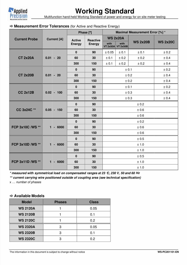
Measurement Error Tolerances (for Active and Reactive Energy)
Current Probe Current [A]
Phase [°°°°] Maximal Measurement Error [%] *
ActiveEnergy
ReactiveEnergy
WS 2x20AWS 2x20B WS 2x20C
with
VT 2x50A
with
VT 2x50B
CT 2x20A 0.01 - 20
0 90 ± 0.05 ± 0.1 ± 0.1 ± 0.2
60 30 ± 0.1 ± 0.2 ± 0.2 ± 0.4
300 150 ± 0.1 ± 0.2 ± 0.2 ± 0.4
CT 2x20B 0.01 - 20
0 90 ± 0.1 ± 0.2
60 30 ± 0.2 ± 0.4
300 150 ± 0.2 ± 0.4
CC 2x12B 0.02 - 100
0 90 ± 0.1 ± 0.2
60 30 ± 0.3 ± 0.4
300 150 ± 0.3 ± 0.4
CC 3x24C ** 0.05 - 150
0 90 ± 0.2
60 30 ± 0.6
300 150 ± 0.6
FCP 3x10C /WS ** 1 - 6000
0 90 ± 0.2
60 30 ± 0.6
300 150 ± 0.6
FCP 3x10D /WS ** 1 - 6000
0 90 ± 0.5
60 30 ± 1.0
300 150 ± 1.0
FCP 3x11D /WS ** 1 - 6000
0 90 ± 0.5
60 30 ± 1.0
300 150 ± 1.0
* measured with symmetrical load on compensated ranges at 23 °C, 230 V, 50 and 60 Hz
** current carrying wire positioned outside of coupling area (see technical specification)
x … number of phases
Available Models
Model Phases Class
WS 2120A 1 0.05
WS 2120B 1 0.1
WS 2120C 1 0.2
WS 2320A 3 0.05
WS 2320B 3 0.1
WS 2320C 3 0.2
8/6/2019 Ws2x20 Pc En
http://slidepdf.com/reader/full/ws2x20-pc-en 4/4
Working StandardMultifunction hand-held Working Standard of power and energy for on site meter testing
The information in this document is subject to change without notice WS-PC201101-EN
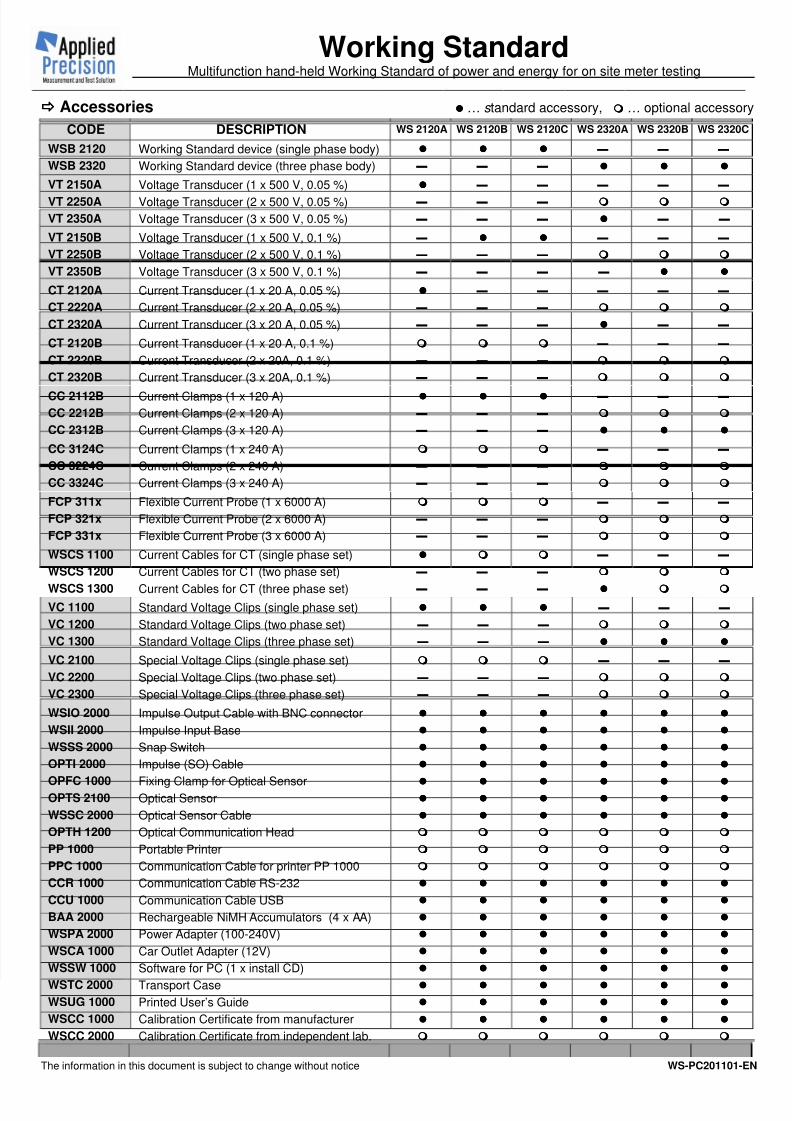
Accessories … s tandard accessory, … optional accessory
CODE DESCRIPTION WS 2120A WS 2120B WS 2120C WS 2320A WS 2320B WS 2320C
WSB 2120 Working Standard device (single phase body) ▬ ▬ ▬
WSB 2320 Working Standard device (three phase body) ▬ ▬ ▬
VT 2150A Voltage Transducer (1 x 500 V, 0.05 %) ▬ ▬ ▬ ▬ ▬
VT 2250A Voltage Transducer (2 x 500 V, 0.05 %) ▬ ▬ ▬
VT 2350A Voltage Transducer (3 x 500 V, 0.05 %) ▬ ▬ ▬ ▬ ▬
VT 2150B Voltage Transducer (1 x 500 V, 0.1 %) ▬ ▬ ▬ ▬
VT 2250B Voltage Transducer (2 x 500 V, 0.1 %) ▬ ▬ ▬
VT 2350B Voltage Transducer (3 x 500 V, 0.1 %) ▬ ▬ ▬ ▬
CT 2120A Current Transducer (1 x 20 A, 0.05 %) ▬ ▬ ▬ ▬ ▬
CT 2220A Current Transducer (2 x 20 A, 0.05 %) ▬ ▬ ▬
CT 2320A Current Transducer (3 x 20 A, 0.05 %) ▬ ▬ ▬ ▬ ▬
CT 2120B Current Transducer (1 x 20 A, 0.1 %) ▬ ▬ ▬
CT 2220B Current Transducer (2 x 20A, 0.1 %) ▬ ▬ ▬
CT 2320B Current Transducer (3 x 20A, 0.1 %) ▬ ▬ ▬
CC 2112B Current Clamps (1 x 120 A) ▬ ▬ ▬
CC 2212B Current Clamps (2 x 120 A) ▬ ▬ ▬
CC 2312B Current Clamps (3 x 120 A) ▬ ▬ ▬
CC 3124C Current Clamps (1 x 240 A) ▬ ▬ ▬
CC 3224C Current Clamps (2 x 240 A) ▬ ▬ ▬
CC 3324C Current Clamps (3 x 240 A) ▬ ▬ ▬
FCP 311x Flexible Current Probe (1 x 6000 A) ▬ ▬ ▬
FCP 321x Flexible Current Probe (2 x 6000 A) ▬ ▬ ▬
FCP 331x Flexible Current Probe (3 x 6000 A) ▬ ▬ ▬
WSCS 1100 Current Cables for CT (single phase set) ▬ ▬ ▬
WSCS 1200 Current Cables for CT (two phase set) ▬ ▬ ▬
WSCS 1300 Current Cables for CT (three phase set) ▬ ▬ ▬
VC 1100 Standard Voltage Clips (single phase set) ▬ ▬ ▬
VC 1200 Standard Voltage Clips (two phase set) ▬ ▬ ▬
VC 1300 Standard Voltage Clips (three phase set) ▬ ▬ ▬
VC 2100 Special Voltage Clips (single phase set) ▬ ▬ ▬
VC 2200 Special Voltage Clips (two phase set) ▬ ▬ ▬
VC 2300 Special Voltage Clips (three phase set) ▬ ▬ ▬
WSIO 2000 Impulse Output Cable with BNC connector
WSII 2000 Impulse Input Base
WSSS 2000 Snap Switch
OPTI 2000 Impulse (SO) Cable
OPFC 1000 Fixing Clamp for Optical Sensor
OPTS 2100 Optical Sensor
WSSC 2000 Optical Sensor Cable
OPTH 1200 Optical Communication Head
PP 1000 Portable Printer
PPC 1000 Communication Cable for printer PP 1000
CCR 1000 Communication Cable RS-232
CCU 1000 Communication Cable USB
BAA 2000 Rechargeable NiMH Accumulators (4 x AA)
WSPA 2000 Power Adapter (100-240V)
WSCA 1000 Car Outlet Adapter (12V)
WSSW 1000 Software for PC (1 x install CD)
WSTC 2000 Transport Case
WSUG 1000 Printed User’s Guide
WSCC 1000 Calibration Certificate from manufacturer
WSCC 2000 Calibration Certificate from independent lab.