Embed Size (px)
Citation preview

CAUTIONTHE FOLLOWING SAFETY PRECAUTIONS SHOULD BE THOROUGHLY UNDERSTOOD
BEFORE ATTEMPTING TO BEGIN ASSEMBLING THIS MACHINE
1. Select an area for assembly that is clean and free of anydebris which might cause persons working on theassembly to trip.
2. Do not lift heavy parts or assemblies. Use crane, jack,tackle, fork trucks or other mechanical devices.
3. Preview the assembly instructions in your operator’smanual before proceeding further.
4. If the assembly instructions call for parts or assemblies tobe blocked up, use only blocking material that is in goodcondition and is capable of handling the weight of theassembly to be blocked. Also insure that the blockingmaterial is on a clean, dry surface.
5. Never put hands, or any part of body, under blocked upassemblies if at all possible.
6. After completing assembly, thoroughly inspect themachine to be sure that all nuts, bolts, hydraulic fittingsor any other fastened assemblies have been thoroughlytightened.
7. Before operating the machine, thoroughly read theoperation section of your operator’s manual.
8. Before operating, read the maintenance section of youroperator’s manual to be sure that any parts requiringlubrication, such as gearboxes, are full, to avoid anypossible damage.
9. Before operating equipment – If you have anyquestions regarding the proper assembly oroperation, contact your dealer or representative.
OWNER’S/OPERATOR’S
MANUAL
MODEL NO.’s
SG-26A
SG-36A
CAUTIONFor Safe Operation
Read Rules AndInstructions Carefully
SI NO LEEINGLES, PIDA AYUDAA AIGUIEN QUE SI LO LEAPARA QUE LE TRADUZCA LASMEDIDAS DE SEGURIDAD.
STUMP GRINDERSfor
TRACTORS
Safety Instructions Assembly & MountingTractor Preparation MaintenanceOperating Instructions Repair Parts

1
TABLE OF CONTENTSWARRANTY . . . . . . . . . . . . . . . . . . . . . . . . . . . . . . . . . . . . . . . 2
SPECIFICATIONS . . . . . . . . . . . . . . . . . . . . . . . . . . . . . . . . . . 3
CHECKLISTS . . . . . . . . . . . . . . . . . . . . . . . . . . . . . . . . . . . . . . 4
SAFETY INFORMATION . . . . . . . . . . . . . . . . . . . . . . . . . . . . . 5
SAFETY SIGNS . . . . . . . . . . . . . . . . . . . . . . . . . . . . . . . . . . . . 14
PREPARATION INSTRUCTIONS – TRACTOR . . . . . . . . . . . . 16
ASSEMBLY INSTRUCTIONS – TRACTOR . . . . . . . . . . . . . . . 17
OPERATING INSTRUCTIONS . . . . . . . . . . . . . . . . . . . . . . . . . 20
OWNER MAINTENANCE & LUBRICATION . . . . . . . . . . . . . . 25
TROUBLE-SHOOTING . . . . . . . . . . . . . . . . . . . . . . . . . . . . . . 28
PARTS LISTS . . . . . . . . . . . . . . . . . . . . . . . . . . . . . . . . . . . . . . 32
TO THE OWNER:Read this manual before using your Stump Grinder. This manual is provided to give you the necessary operat-
ing and maintenance instructions for keeping your Stump Grinder in top operating condition. Please read thismanual thoroughly. Understand what each control is for and how to use it. Observe all safety signs on the machineand noted throughout the manual for safe operation of implement. Keep this manual handy for ready reference.
Like all mechanical products, it will require cleaning and upkeep. Lubricate the Stump Grinder as specified.
Use only genuine Worksaver, Inc. service parts. Substitute parts will void the warranty and may not meet stan-dards required for safe and satisfactory operation. Record the model and serial number of your Stump Grinderhere:
Model:________________________________________ Serial Number:_______________________________
RETAIL CUSTOMER’S RESPONSIBILITYIt is the Retail Customer and/or Operator’s responsibility to read the Operator’s Manual, to operate, lubri-
cate, maintain, and store the product in accordance with all instructions and safety procedures. Failureof the operator to read the Operator’s Manual is a misuse of this equipment.
It is the Retail Customer and/or Operator’s responsibility to inspect the product and to have any part(s)repaired or replaced when continued operation would cause damage or excessive wear to other parts orcause a safety hazard.
It is the Retail Customer’s responsibility to deliver the product to the authorized Worksaver Dealer, fromwhom he purchased it, for service or replacement of defective parts which are covered by warranty.Repairs to be submitted for warranty consideration must be made within forty-five (45) days of failure.
It is the Retail Customer’s responsibility for any cost incurred by the Dealer for traveling to or haulingof the product for the purpose of performing a warranty obligation or inspection.
SI NO LEEINGLES, PIDA AYUDA AAIGUIEN QUE SI LO LEA PARA QUELE TRADUZCA LAS MEDIDAS DESEGURIDAD.
STATEMENTOF POLICY
It is the policy of Worksaver,Inc. to improve its products whereit is possible and practical to doso. Worksaver, Inc. reserves theright to make changes orimprovements in design and con-struction at any time, withoutincurring the obligation to makethese changes on previouslymanufactured units.

2
LIMITED WARRANTY✯ ✯ ✯ ✯ ✯ ✯ ✯ ✯ ✯ ✯ ✯ ✯ ✯ ✯ ✯ ✯ ✯ ✯ ✯ ✯ ✯ ✯ ✯ ✯ ✯ ✯ ✯
Worksaver warrants to the original purchaser of any new Stump Grinder (Models SG-26A and SG-36A), thatthe equipment be free from defects in material and workmanship for a period of one (1) year for non-commercial, state, and municipalities’ use ninety (90) days for commercial use from date of retail sale.
Replacement or repair parts installed in the equipment covered by this warranty are warranted for ninety (90)days from the date of purchase of such part or to the expiration of the applicable new equipment warrantyperiod, whichever occurs later.
Such parts shall be provided at no cost to the user during regular working hours. Worksaver reserves the rightto inspect any equipment or parts which are claimed to have been defective in material or workmanship.
DISCLAIMER OF IMPLIED WARRANTIES & CONSEQUENTIAL DAMAGES
Worksaver’s obligation under this warranty, to the extent allowed by law, is in lieu of all warranties, implied orexpressed, including implied warranties of merchantability and fitness for a particular purpose and any liabili-ty for incidental and consequential damages with respect to the sale or use of the items warranted. Suchincidental and consequential damages shall include but not be limited to: transportation charges other thannormal freight charges; cost of installation other than cost approved by Worksaver; duty; taxes; charges for nor-mal service or adjustments; loss of crops or any other loss of income; rental of substitute equipment, expens-es due to loss, damage, detention or delay in the delivery of equipment or parts resulting from acts beyond thecontrol of Worksaver.
THIS WARRANTY SHALL NOT APPLY:
1. To vendor items which carry their own warranties, such as hydraulic cylinders and hydraulic motor.
2. If the unit has been subjected to misapplication, abuse, misuse, negligence, fire or other accident.
3. If parts not made or supplied by Worksaver have been used in connection with the unit, if, in sole judge-ment of Worksaver such use affects its performance, stability, or reliability.
4. If the unit has been altered or repaired outside of an authorized Worksaver dealership in a manner which,in the sole judgement of Worksaver affects its performance, stability or reliability.
5. To normal maintenance service and normal replacement items such as gearbox lubricant, hydraulic fluid,worn blades, or to normal deterioration of such things as belts and exterior finish, due to use or exposure.
6. To expendable or wear items such as teeth, chains, sprockets, belts, springs and other items that in thecompany’s sole judgement is a wear item.
NO EMPLOYEE OR REPRESENTATIVE OF WORKSAVER IS AUTHORIZED TO CHANGE THIS WARRAN-TY IN ANY WAY OR GRANT ANY OTHER WARRANTY UNLESS SUCH CHANGE IS MADE IN WRITINGAND SIGNED BY WORKSAVER’S SERVICE MANAGER, POST OFFICE BOX 100, LITCHFIELD, ILLINOIS62056-0100.
✯ ✯ ✯ ✯ ✯ ✯ ✯ ✯ ✯ ✯ ✯ ✯ ✯ ✯ ✯ ✯ ✯ ✯ ✯ ✯ ✯ ✯ ✯ ✯ ✯ ✯ ✯

3
STUMP GRINDER SPECIFICATIONS
SUBJECT MODEL SG-26A MODEL SG-36A
Mounting Cat. I - 3 pt. Cat. I / II - 3 pt.
Recommended hp / Flow Req’d 22 - 45 PTO 45 - 100 PTO
# Hyd. Remote Outlets Reg. 2 2
Weight of Unit 660 lbs. 880 lbs.
Max Stump Height 18” 18”
Max Cutting Depth 10” 15”
Total Vertical Movement (Wheel) 28” 33”
Grinding Wheel Diameter 26” 36”
Grinding Wheel Speed (rpm) 810 788
Cutting Wheel Tip Speed (ft./min.) 5,515 7,430
Cutting Arc (degrees) 45° 45°
# Cutting Teeth 33 42
Gearbox Ratio 1:1.5 1:1.46
Gearbox (hp rating) 60 hp 100 hp
Input rpm 540 rpm 540 rpm
Output rpm 810 788
Gearbox Warranty Limited 1 year Limited 1 year
Gearbox Lubrication 90 w/ gear oil 90 w/ gear oil
PTO Driveline (Metric Series) Metric Series 5 Metric Series 6
PTO Driveline Length (closed) 50” 541/4”
Swing Cylinder (Hyd.) 2” x 24” 2” x 24”
Depth Cylinder (Hyd.) 21/2” x 10” 21/2” x 10”

4
DAILY CHECKLIST
■■ Check that stump grinder is properly and securelyattached to tractor.
■■ During inspection, check that all nuts and bolts aresecure and that all safety shields are in place.
■■ It is very important that the cutting teeth and cuttingtooth bolts are checked and tightened frequently.
■■ Check condition of grinding wheel and security ofattachment.
■■ Do not put stump grinder into service unless cuttingteeth edges are intact and in good repair.
■■ Do not put stump grinder into service unless allshields and guards are in place and in good condi-tion. Replace if damaged.
■■ Make sure spring-activated locking pin or collarslides freely and is seated firmly in tractor PTOspline groove.
■■ Consult local utilities before working. Know locationof all underground cables, pipelines, overheadwires, and other hazards in working area and avoidcontact.
■■ Always wear relatively tight and belted clothing toavoid entanglement in moving parts. Wear sturdy,rough-soled work shoes and protective equipmentfor eyes, hair, hands, hearing, and head.
DELIVERY CHECKLIST
Inspect the stump grinder thoroughly after assembly tobe certain it is set up properly. The following checklist isa reminder of points to inspect. Check off each item as itis found satisfactory or after proper adjustment is made.
■■ Check operator's manual and familiarize the opera-tor with all sections of it.
■■ Check that all safety shielding is in place.
■■ Check all bolts to be sure they are tight or adjustedproperly at hinged locations.
■■ Check that all cotter pins are properly installed.
■■ Check PTO driveline. Make sure it is the correctlength to operate stump grinder with intended trac-tor.
■■ Check that all lubrication points with grease fittingshave been lubricated.
■■ Check that carbide teeth have been properlyinstalled. Check all cutting tooth bolts.
■■ Check stump grinder attitude, after mounting ontractor.
■■ Check that gearbox is properly serviced and sealsare not leaking.
■■ All safety signs (decals) in place and readable.
■■ When the stump grinder is transported on a road orhighway at night or during the day, safety devicesshould be used for adequate warning to operators ofother vehicles.
CHECKLISTS
IMPORTANT!Gearbox was not filled at factory. It must be serviced before operating. Fill toproper level with SAE 90 oil. Failure to service will result in damage to gearbox.

5
To the Owner/Operator/DealerAll implements with moving parts are potentially hazardous. There is no substitute for a cautious, safe-minded opera-tor who recognizes the potential hazards and follows reasonable safety practices. The manufacturer has designed thisimplement to be used with all its safety equipment properly attached to minimize the chance of accidents.
BEFORE YOU START!!Read the safety messages on the implement and shown in your manual.
Observe the rules of safety and common sense!
THIS SAFETY ALERT SYMBOL IDENTIFIES IMPORTANTSAFETY WARNING MESSAGES. CAREFULLY READ EACHWARNING MESSAGE THAT FOLLOWS. FAILURE TOUNDERSTAND AND OBEY A SAFETY WARNING, ORRECOGNIZE A SAFETY HAZARD, COULD RESULT IN ANINJURY OR DEATH TO YOU OR OTHERS AROUND YOU.THE OPERATOR IS ULTIMATELY RESPONSIBLE FOR THESAFETY OF HIMSELF, AS WELL AS OTHERS, IN THEOPERATING AREA OF THE TRACTOR AND EQUIPMENT.
THIS SYMBOL MEANS
– ATTENTION!
– BECOME ALERT!
– YOUR SAFETY IS INVOLVED!
UNDERSTAND SIGNAL WORDS
Indicates an imminently hazardous situation that, if not avoided, WILL result inDEATH OR VERY SERIOUS INJURY.
Indicates a imminently hazardous situation that, if not avoided, COULD result inDEATH OR SERIOUS INJURY.
Indicates a imminently hazardous situation that, if not avoided, MAY result inMINOR INJURY.
Identifies special instructions or procedures that, if not strictly observed, couldresult in damage to, or destruction of the machine, attachments or the environment.
NOTE: Identifies points of particular interest for more efficient and convenient operation or repair.
If you have questions not answered in this manual or require additional copies or the manual is damaged, pleasecontact your dealer or the manufacturer directly.
WARNING
DANGER
CAUTION
IMPORTANT
IMPORTANT SAFETY INFORMATION!Working with equipment can lead to injuries. Read this manual, and the manual for your tractor, before assembly oroperating, to acquaint yourself with the machines. It is the implement owner’s responsibility, if this machine is used byany person other than yourself, is loaned or rented, to make certain that the operator, prior to operating:
1. Reads and understands the operator’s manuals.2. Is instructed in safe and proper use.
The use of this equipment is subject to certain hazards which cannot be protected against by mechanicalmeans or product design. All operators of this equipment must read and understand this entire manual, pay-ing particular attention to safety and operating instructions, prior to using. If there is something in this manu-al you do not understand, ask your supervisor, or your dealer, to explain it to you.

6
SAFETY INSTRUCTIONS (continued)
Safety of the operator is one of the main concerns in designing and developing a new piece of equipment.Designers and manufacturers build in as many safety features as possible. However, every year manyaccidents occur which could have been avoided by a few seconds of thought and a more careful approach tohandling equipment.You, the operator, can avoid many accidents by observing the following precautions in thissection. To avoid personal injury, study the following precautions and insist those working with you, or for you,follow them.
Personal protection equipment including hard hat, safety glasses, safety shoes, and gloves are recommendedduring assembly, installation, operation, adjustment, maintaining, repairing, removal, or moving the implement.Do not allow long hair, loose fitting clothing or jewelry to be around moving parts.
To prevent injury or death, use a tractor equipped with a Roll-Over Protective System (ROPS). Keep foldableROPS systems in “locked up” position at all times. Keep seat belt fastened.
Never exceed the limits of a piece of machinery. If its ability to do a job, or to do so safely, is in question –DON’T TRY IT.
Do not modify the equipment in any way. Unauthorized modification may impair the function and/or safety andcould affect the life of the equipment.
In addition to the design and configuration of this implement, including safety signs and safety equipment,hazard control and accident prevention are dependent upon the awareness, concern, prudence, and propertraining of personnel involved in the operation, transport, maintenance, and storage of the machine. Refer alsoto safety messages and operation instructions in each of the appropriate sections of the tractor and stumpgrinder manuals. Pay close attention to the safety signs affixed to the tractor and the stump grinder.
Replace any CAUTION, WARNING, DANGER or instruction safety sign that is not readable or is missing.Location of such safety signs is indicated in this booklet. Do not paint over, remove or deface any safety signsor warning signs on your equipment. Observe all safety signs and practice the instruction on them.
Never use alcoholic beverages or drugs which can hinder alertness or coordination while operating thisequipment. Consult your doctor about operating this machine while taking prescription medications.
Review the safety instructions with all users annually.
This equipment is dangerous to children and persons unfamiliar with its operation. The operator should be aresponsible adult familiar with farm machinery and trained in this equipment’s operations. Do not allow per-sons to operate or assemble this unit until they have read this manual and have developed a thoroughunderstanding of the safety precautions and of how it works.
EQUIPMENT SAFETY GUIDELINES

7
SAFETY INSTRUCTIONS (continued)
Never operate the tractor or stump grinder until you have read and completely understand this manual, thetractor operator’s manual, and each of the safety messages found on the safety signs on the tractor or stumpgrinder.
Clear area where stump is to be cut of stones, branches or other debris that might be thrown, causing injuryor damage. Before starting machine, remove loose chunks of wood or other objects from stump and work area.
Operate only in daylight or good artificial light.
Ensure stump grinder is properly mounted, adjusted and in good operating condition.
Make sure driveline spring-activated locking pin or balls operate freely and are seated firmly in tractor PTOstub shaft groove.
Ensure that all safety shielding and safety signs are properly installed and in good condition.
Operate the stump grinder only with a tractor equipped with an approved Roll-Over Protective System (ROPS).Always wear your seat belt on tractors equipped with a ROPS. Serious injury or even death could result fromfalling off the tractor – particularly during a turnover when the operator could be pinned under the ROPS or thetractor. Keep foldable ROPS systems in “locked up” position at all times.
PROLONGED EXPOSURE TO LOUD NOISE MAY CAUSE PERMANENT HEARING LOSS!Power units with or without implements attached can often be noisy enough to cause permanent, partial hear-ing loss. We recommend that you wear hearing protection on a full-time basis if the noise in the Operator’sposition exceeds 80db. Noise over 85db on a long-term basis can cause severe hearing loss. Noise over 90dbadjacent to the Operator over a long-term basis may cause permanent, total hearing loss. NOTE: Hearing lossfrom loud noise (from tractors, chain saws, radios, and other such sources close to the ear) is cumulative overa lifetime without hope of natural recovery.
PREPARATION
Make sure that all operating and service personnel know that in the event hydraulic fluid penetrates the skin,it must be surgically removed within a few hours by a physician familiar with this form of injury, or gangrenemay result.
Consult local utility companies (Call 811) to make certain there are no buried gas lines, electrical cables, etc.,in the work area before beginning operation.

8
SAFETY INSTRUCTIONS (continued)
PTO powered stump grinder’s operating power is supplied from tractor PTO. Refer to your tractor manual forPTO engagement and disengagement instructions. Always operate PTO at 540 RPM. Know how to stop trac-tor and stump grinder quickly in case of an emergency.
The addition of a separate over-running PTO clutch attachment will change the length of the PTO driveline.Pay extra attention to the instructions on PTO driveline installation.
Separate over-running clutch attachments will increase the length of the driveline and may cause the frontknuckle joint to operate beyond the cover of the tractor master shield. This is NOT recommended and willpresent a dangerous operating condition.
The use of this equipment is subject to certain hazards which cannot be protected against by mechanicalmeans or product design. All operators of this equipment must read and understand this entire manual,paying particular attention to safety and operating instructions, prior to using. If there is something in thismanual you do not understand, ask your supervisor, or your dealer, to explain it to you.
Keep all helpers and bystanders at least a hundred feet (100 ft.) from an operating stump grinder. Only prop-erly trained people should operate this machine.
The majority of accidents involve entanglement on the driveline, injury of bystanders by objects thrown by thegrinding wheel, and operators being knocked off the tractor by low hanging limbs and then being run over bythe equipment. Accidents are most likely to occur with machines that are loaned or rented to someone whohas not read the owner’s manual and is not familiar with a stump grinder.
Check the tractor master shield over the PTO stub shaft. Make sure it is in good condition and fastenedsecurely to the tractor. Purchase a new shield if old shield is damaged or missing. (You may have to use atractor salvage yard for replacement parts on older tractors.)
When engaging PTO, the engine RPM should always be low. Once engaged and ready to start cutting, raisePTO speed to 540 RPM and maintain throughout stump grinding operation.
STARTING AND STOPPING SAFETY
OPERATIONAL SAFETY
Start tractor only when properly seated in the tractor seat. Starting a tractor in gear can result in injury or death.Do not mount or dismount the tractor while the tractor is moving. Mount or dismount the tractor only when thetractor and all moving parts are completely stopped.

9
SAFETY INSTRUCTIONS (continued)
Always stop the power unit, set brake, shut off the engine, remove the ignition key, lower implement to theground and allow grinding wheel to come to a complete stop before dismounting. Never leave equipment unat-tended with the power unit running.
Never place hands or feet under stump grinder with power unit engine running or before you are sure all motionhas stopped. Stay clear of all moving parts. Keep hands, feet, hair, and clothing away from moving parts.
Do not reach or place yourself under equipment until it is blocked securely.
Take all possible precautions when leaving unit unattended: Disengage PTO, set parking brake, stop engineand remove key from ignition. Park in level area.
Do not allow riders on the stump grinder or power unit at any time. There is no safe place for any riders.
Disengage power takeoff (PTO) or hydraulic power and place transmission into neutral before attempting tostart engine.
Do not operate unless all personnel, livestock, and pets are a hundred feet away to prevent injury by thrownobjects. Never direct discharge toward anyone.
Install and secure all guards and shields before starting or operating.
PTO powered stump grinders are designed for use only on tractors with 540 RPM power takeoff.
Never operate tractor and stump grinder under trees with low hanging limbs. Operators can be knocked off thetractor and then run over by the equipment.
Frequently check cutting teeth. They should be sharp, free of nicks and cracks and securely fastened.
Many varied objects, such as wire, cable, rope, or chains, can become entangled in the grinding wheel. Theseitems could then swing outside the housing at great velocities. Such a situation is extremely hazardous. Inspectthe cutting area for such objects before grinding stumps. Removing any like object from the site. Never allowthe grinding wheel to contact such items.
Pick up all rocks and other debris before grinding stumps. Enter new areas carefully. Never assume an area isclear. Always Check!
OPERATIONAL SAFETY (continued)
The rotating parts of this machine have been designed and tested for rugged use. However, they could failupon impact with heavy, solid objects such as steel posts, and other hard foreign material. Such impact couldcause the broken objects to be thrown outward at very high velocities. To reduce the possibility of propertydamage, serious injury, or even death, try to never allow the grinding wheel to contact such obstacles. Treeswill sometimes grow around foreign objects so they cannot always be seen. Be extra cautious when grindingtree stumps near buildings or in fence rows.

10
SAFETY INSTRUCTIONS (continued)
Stop stump grinder and power unit immediately upon striking an obstruction. Turn engine off, remove key,inspect and repair any damage before resuming operation.
The guards, flaps, driveline shields, and gearbox shields should be used and maintained in good workingcondition. They should be inspected carefully, at least daily, for missing or broken shields, or guards. Missingbroken, or worn items must be replaced at once to reduce the possibility of injury from thrown objects orentanglement.
Use extreme care and maintain minimum ground speed when transporting on hillside, over rough ground andwhen operating close to ditches or fences. Be careful when turning sharp corners.
Reduce speed on slopes and sharp turns to minimize tipping or loss of control. Be careful when changingdirections on slopes. Do not start or stop suddenly on slopes. Avoid operation on steep slopes.
When using a tractor mounted unit, a minimum 20% of tractor and equipment weight must be on tractor frontwheels. Without this weight, tractor could tip over, causing personal injury or death. The weight may be attainedwith a front end loader, front wheel weights, ballast in tires of front tractor weights. When attaining a minimum20% of tractor and equipment weight on the front wheels, you must not exceed the ROPS weight certification.Weigh the tractor and equipment. Do not guess or estimate!
Inspect the entire machine periodically as indicated in the Maintenance Section of this manual. Look for loosefasteners, worn or broken parts, pinched hydraulic hoses, and leaky or loose fittings. Make sure all pins havecotter pins and washers. Serious injury may occur from not maintaining this machine in good working order.
Stay alert for holes, rocks and roots in the terrain and other hidden hazards. Keep away from drop-offs.
In extremely uneven terrain, real wheel weights, front tractor weight, and/or tire ballast should be used toimprove stability.
Be careful when operating power unit and stump grinder on uneven ground to avoid upsetting.
Pass diagonally through sharp dips and avoid sharp drops to prevent “hanging up” power unit and stumpgrinder. Practice will improve your skills in maneuvering rough terrain.
Avoid sudden starts and stops while traveling up or downhill.
OPERATIONAL SAFETY (continued)

11
SAFETY INSTRUCTIONS (continued)
Comply with state and local laws governing highway safety and movement of farm machinery on public roads.
The use of flashing amber lights is acceptable in most localities. However, some localities prohibit their use.Local laws should be checked for all highway lighting and marking requirements.
When driving the tractor and equipment on the road or highway under 20 mph (32 kph) at night or during theday, use flashing amber warning lights and a slow moving vehicle (SMV) identification emblem.
Always be sure the implement is in the proper raised position for transport.
Reduce speed when transporting mounted implements to avoid bouncing and momentary loss of steeringcontrol.
Plan your route to avoid heavy traffic.
Always install transport locks, pins or brackets before transporting.
Do not drink and drive!
Watch for traffic when operating near or crossing roadways.
Turn curves or go up or down hills only at a low speed and at a gradual steering angle. Make certain that atleast 20% of the tractor’s weight is on the front wheels to maintain safe steerage. Slow down on rough oruneven surfaces, and loose gravel.
Use extreme care and maintain minimum ground speed when transporting on hillside, over rough ground andwhen operating close to ditches or fences. Be careful when turning sharp corners.
Never allow riders on either power unit or stump grinder. Falling off can kill.
Be a safe and courteous driver. Always yield to oncoming traffic in all situations, including narrow bridges,intersections, etc.
Do not exceed 20 mph (32 kph). Reduce speed on rough roads and surfaces.
TRANSPORT SAFETY

12
SAFETY INSTRUCTIONS (continued)
MAINTENANCE SAFETY
Good maintenance is your responsibility. Poor maintenance is an invitation to trouble.
Before working on this machine, drive to a level area, disengage the PTO, lower implement (or if workingunderneath, raise and block securely), shut off the engine, set the brakes, and remove the ignition keys.Remove hydraulic pressure prior to doing any maintenance. Operate the remote hydraulic control lever in andout several times to relieve hydraulic pressure.
Be certain all moving parts on attachments have come to a complete stop before attempting to performmaintenance.
Never work under equipment unless it is blocked securely. Never depend on hydraulic system to keep imple-ment in raised position.
Always use personal protection devices such as eye, hand and hearing protectors, when performing anyservice or maintenance.
Keep all persons away from operator control area while performing adjustments, service, or maintenance.
Periodically tighten all bolts, nuts and screws and check that all cotter pins are properly installed to ensure unitis in a safe condition.
When completing a maintenance or service function, make sure all safety shields and devices are installedbefore placing unit in service.
Never use your hands to locate a hydraulic leak on attachments. Use a small piece of cardboard or wood.Hydraulic fluid escaping under pressure can penetrate the skin.
Openings in the skin and minor cuts are susceptible to infection from hydraulic fluid. If injured by escapinghydraulic fluid, see a doctor at once. Gangrene and death can result. Without immediate medical treatment,serious infection and reactions can occur.
Check to ensure all safety signs are installed and in good condition.
Where replacement parts are necessary for periodic maintenance and servicing, genuine factory replacement partsmust be used to restore your equipment to original specifications. The manufacturer will not claim responsibility for useof unapproved parts and/or accessories and other damages as a result of their use.
If equipment has been altered in any way from original design, the manufacturer does not accept any liability for injuryor warranty.
Frequently check carbide tipped cutting teeth. They should be sharp, free of nicks and cracks and securely fas-tened. Rotate teeth for even wear – outer teeth wear faster.

13
SAFETY INSTRUCTIONS (continued)
Following operation, or when unhooking, stop the tractor, set the brakes, lower ram to lowest position andengage transport lock pin, shut off the engine, relieve hydraulic pressure and remove the ignition keys.
Store the unit in an area away from human activity.
Do not park equipment where it will be exposed to livestock for long periods of time. Damage and livestockinjury could result.
Do not permit children to play on or around the stored unit.
Make sure all parked machines are on a hard, level surface and engage all safety devices.
If blocking is used, make sure it is solid and secure before leaving area.
STORAGE SAFETY
Keep safety signs clean and legible at all times.
Replace safety signs that are missing or have become illegible.
Replaced parts that displayed a safety sign should also display the current sign.
Safety signs are available from your Distributor or Dealer Parts Department or the factory.
How to Install Safety Signs:
• Be sure that the installation area is clean and dry.
• Be sure temperature is above 50°F (10°C).
• Decide on the exact position before you remove the backing paper.
• Remove the smallest portion of the split backing paper.
• Align the sign over the specified area and carefully press the small portion with the exposed sticky backing in place.
• Slowly peel back the remaining paper and carefully smooth the remaining portion of the sign in place.
• Small air pockets can be pierced with a pin and smoothed out using the piece of sign backing paper.
SAFETY SIGNS

14
WARNING540 RPM SPEED
RANGE ONLYHIGHER PTO SPEEDS CAN CAUSE
PERSONAL INJURY ANDEQUIPMENT FAILURE
101101
SAFETY SIGNS
REMEMBER: If Safety Signs have been damaged, removed, become illegible or parts replaced without Signs,new Safety Signs must be applied. New Safety Signs are available from your authorized distributor or factory.
BE CAREFUL! Use a clean, damp cloth to clean safety decals. Avoid spraying to close to decals when usinga pressure washer; high-pressure water can enter through very small scratches or under edges of decals causing themto peel or come off.

15
REMEMBER: If Safety Signs have been damaged, removed, become illegible or parts replaced without Signs,new Safety Signs must be applied. New Safety Signs are available from your authorized distributor or factory.
BE CAREFUL! Use a clean, damp cloth to clean safety decals. Avoid spraying to close to decals when usinga pressure washer; high-pressure water can enter through very small scratches or under edges of decals causing themto peel or come off.
SAFETY SIGNS (continued)
16
The model SG-26 requires a tractor of at least 22 hp orup to a maximum of 45 hp and a Category I, 3 pt. hitch.
The model SG-36 requires a tractor of at least 45 hp orup to a maximum of 100 hp and a Category I or II, 3 pt.hitch.
The tractor also needs lift arm stabilizer bars or swayblocks to control side movement of the stump grinder.Adjust as tightly as practical for best performance.
Check the tractor’s 3 pt. hydraulic lift system. Refer toyour tractor operator’s manual or dealer for any adjust-ments necessary to put the hydraulic system in goodworking order. (I&T shop manuals will list most specifica-tions and adjustment instructions – available from mostfarm equipment dealers.)
Tractor must be equipped with two (2) independent pairof remote hydraulic outlets to operate these stumpgrinders.
Be sure tires and rims are in good condition. Inflate tiresto the proper recommended air pressure.
Check the tractor master shield over the PTO stub shaft.Make sure it is in good condition and fastened securelyto the tractor. Purchase a new shield if old shield isdamaged or missing. (You may have to use a tractorsalvage yard for replacement parts on older tractors.)
It is recommended that a ROPS (Roll-Over ProtectionStructure) and a seat belt be installed on all tractors.Keep foldable ROPS systems in “locked up” position at alltimes. Contact your local dealer for a ROPS for yourtractor.
Most swinging drawbars will have to be moved to aforward position or removed. Check the tractor swing-ing drawbar for interference with the front of the stumpgrinder. The swinging drawbar can be moved forward onsome tractors or it can be removed.
It is recommended that only tractors with wide frontaxles be used with these stump grinders. Tricycle frontwheel arrangements are inherently unstable and tractorroll-over accidents are more likely to occur.
Be sure your tractor is in good condition. Read allthe safety precautions and make sure all tractoroperators are familiar with the safety rules ofoperation.
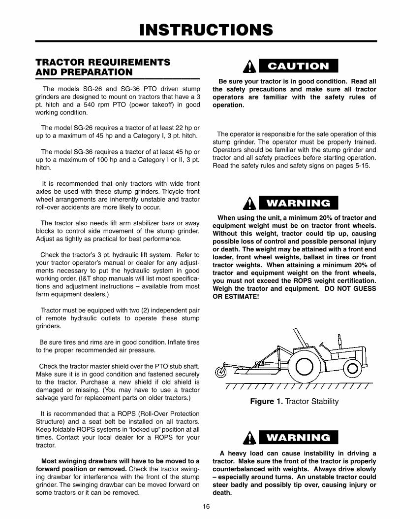
Figure 1. Tractor Stability
When using the unit, a minimum 20% of tractor andequipment weight must be on tractor front wheels.Without this weight, tractor could tip up, causingpossible loss of control and possible personal injuryor death. The weight may be attained with a front endloader, front wheel weights, ballast in tires or fronttractor weights. When attaining a minimum 20% oftractor and equipment weight on the front wheels,you must not exceed the ROPS weight certification.Weigh the tractor and equipment. DO NOT GUESSOR ESTIMATE!
A heavy load can cause instability in driving atractor. Make sure the front of the tractor is properlycounterbalanced with weights. Always drive slowly– especially around turns. An unstable tractor couldsteer badly and possibly tip over, causing injury ordeath.
The operator is responsible for the safe operation of thisstump grinder. The operator must be properly trained.Operators should be familiar with the stump grinder andtractor and all safety practices before starting operation.Read the safety rules and safety signs on pages 5-15.
TRACTOR REQUIREMENTSAND PREPARATION——————————————————
The models SG-26 and SG-36 PTO driven stumpgrinders are designed to mount on tractors that have a 3pt. hitch and a 540 rpm PTO (power takeoff) in goodworking condition.
INSTRUCTIONS
WARNING
WARNING
CAUTION

17
This unit is shipped almost completely assembled.Carefully follow instructions for final assembly.
Before attempting assembly check the following items.Having all the needed parts and equipment readily athand will speed up your assembly task and will make thejob as safe as possible.
• Refer to the repair parts drawing in this manual to getan idea of how the parts need to be assembled foreach individual implement model.
• Check for fasteners and pins that were shipped withthe stump grinder. All hardware coming from the facto-ry has been installed in the location where it will beused. If a part or fastener is temporarily removed forassembly reasons, remember where it goes. Keep theparts separated.
• Have a fork lift or loader along with chains and safetystands that are sized for the job ready for the assem-bly task.
• Have a minimum of 2 people at hand during assembly.
• Check to see that all nuts are tightened.
Never let anyone stand between the rear of the tractorand the stump grinder while the tractor is backing up.Always stand to the side until tractor has come to a com-plete stop and the brakes set or the tractor shift placed in“PARK.”
1) Back tractor to align lift arms with stump grinder hitchpoints.
2) Attach both lower lift arms to stump grinder. Securewith linch pins. Tractor lift arm stabilizer bars or swayblocks must be used to control side movement of thestump grinder. DO NOT CONNECT THE PTO DRIV-ELINE AT THIS TIME.
3) Install suitable top link between tractor and stumpgrinder. Secure with link pins and linch pins.
4) Lift stump grinder and check to see that both 3 pt. liftarms are the same height. Adjust using crank if nec-essary to level the implement from side to side.
To avoid bodily injury caused by accidental fallingof stump grinder, securely support stump grinder onsafe supporting stands or blocks!
INSTRUCTIONS (continued)
1. Drive Shield2. Bolt3. Nut4. Gearbox Input Shaft5. Gearbox Input Shield
Figure 2. Slip Clutch Driveline Installation
Align the holes in the driveline yoke and the groove inthe gearbox input shaft and install bolts (2) and nuts (3).
Lubricate rear driveline half and install front drivelinehalf.
In some cases it will be necessary to shorten the PTOassembly to match your particular tractor. The followingprocedure should be used:
1. Raise the tractor 3 pt. hitch so the input shaft of thegearbox is in line with the PTO shaft on the tractor.Shut down tractor, leaving stump grinder in position ofshortest distance between shafts. SECURELYBLOCK IMPLEMENT IN POSITION.
TRACTOR 3 PT. ASSEMBLYAND MOUNTING——————————————————
PTO DRIVELINE INSTALLATION——————————————————
On new stump grinders, check PTO driveline for correctlength for use with your tractor. (Read page 18.)
Most swinging drawbars will have to be moved to aforward position or removed. Check the tractor swing-ing drawbar for interference with the PTO driveline beforeattempting to lift the stump grinder with the 3 pt. hitch.
Tractor lift arm stabilizer bars or sway blocks must beused to control side movement of the stump grinder.
A new slip clutch, or one that has been in storage overthe winter may seize. Before operating, make sure it willslip. Refer to slip clutch adjustment on page 27.
CAUTION

18
INSTRUCTIONS (continued)
Figure 3
NOTE: The use of a PTO over-running clutch or exten-sion could require that the PTO driveline be shortened aconsiderable amount. If this is done, the driveline halvesmay separate when the stump grinder is lowered to theground or when operated on uneven ground.
NOTE: Because of the above situation, and the use ofPTO extensions extend the front PTO driveline jointbeyond the protection of the tractor PTO shield, the useof PTO extensions and over-running clutches of this typeare not recommended.
4. Swing and lower the stump grinder wheel to deter-mine position with greatest distance between the PTOshaft and gearbox input shaft. Shut tractor off, leavingstump grinder in position of greatest distance betweenshafts. SECURELY BLOCK STUMP GRINDER INPOSITION.
5. Hold driveline sections parallel to each other andcheck for minimum 6” (15cm) overlap. If drivelinehas been marked for cutting, overlap will be thedistance between the two marks. If driveline has lessthan minimum overlap, do not use. Contact authorizedWorksaver dealer.
SLIP CLUTCH DRIVELINE INSTALLATION (cont.)
2. Pull driveline apart. Attach outer (female) section totractor PTO shaft. Pull on driveline section to be surethat yoke locks into place.
3. Hold driveline sections parallel to each other todetermine if too long. Each section should endapproximately 3” (76mm) short of reaching universaljoint shield on opposite section. If too long, measure3” (76mm) back from universal joint shield and markon opposite section (Figure 3). Do this for both sec-tions. DO NOT CUT UNTIL STEPS 4 AND 5 ARECHECKED.
Figure 5
Figure 4
6. If driveline must be cut to a shorter length, clampdriveline in a well padded vise to prevent damage tothe shield. Cut off shield where marked. Using cut-offsection of shield as a guide, cut shaft the sameamount. (Figure 5.)
7. Repeat the procedure to the other driveline half.Remove all burrs and cuttings.
8. Apply multi-purpose grease to inside of outer (female)driveline section. Assemble driveline and install ontractor and stump grinder. Pull on each driveline sec-tion to be sure yokes lock into place. Make certain dri-veline shielding is in place and in good condition.
9. Carefully raise, lower, and swing the stump grinderwheel and check to be sure the PTO assembly doesnot jam. If it does, cut equal amounts from each half ofthe PTO assembly.

19
Figure 6. Stump Grinder Hydraulic Diagram
INSTRUCTIONS (continued)
SLIP CLUTCH DRIVELINE INSTALLATION (cont.)
10. Check the swinging drawbar of the tractor and makesure the PTO driveline assembly will not contact. Theswinging drawbar can be moved forward on sometractors or it can be removed.
If the PTO driveline assembly contacts the swingingdrawbar, damage will occur to the driveshaft shield andpossibly the driveshaft itself. (NOT covered underwarranty.)
When attaching PTO yoke to tractor PTO shaft, it isimportant that spring-activated locking pin or ballsoperate freely and are seated in groove on PTO shaft.A loose shaft could slip off and result in personalinjury or damage to equipment.
Route the hoses to your tractor remote hydrauliccouplers. Be sure to allow a loop of hose just behind theattachment to allow for the angles that will beencountered. Make sure that the hoses are routed sothey will not be pinched or snagged by implement or
tractor parts. Fasten the hoses securely so they willremain in the correct position and not drop down wherethey could be pinched or sheared.
After making the hose connection between the tractorremote outlets and the hydraulic cylinders, operate thecylinders several times to work the air out of the system.
Check hydraulic fluid level in your tractor after filling thecylinders and hoses.
NOTE: If your tractor has a closed center hydraulicsystem, turn the flow control on the remote hydraulicoutlet block to minimum flow.
If your tractor does not have a flow control, contactWorksaver, Inc. for a restrictor orifice fitting to reduce theflow. This will minimize the heat build up in the tractorclosed center hydraulic system.
Order optional throttle valve #2505642 for closedcenter systems (see page 32 for location).
Escaping hydraulic fluid under pressure can pene-trate the skin, causing serious injury.
DO NOT use your hand to check for leaks. Use apiece of cardboard or paper to search for leaks.Stop engine and relieve pressure before connecting
or disconnecting lines.Tighten all connections before starting engine or
pressurizing lines.If any fluid is injected into the skin, obtain medical
attention immediately, or gangrene may result.
INSTRUCTIONS——————————————————
ASSEMBLY (continued)——————————————————
Check the hydraulic hose routing and connections asshown in Figure 6. The hydraulic cylinder circuit thatswings the stump grinder left to right has a pressure reliefvalve to control the side pressure. Connect this reliefvalve as shown.
Use a good thread sealant. (DO NOT USE TEFLONTAPE as this could cause hydraulic system problems inyour tractor.)
The hydraulic circuits for both cylinders contain anorifice to provide a controllable rate of movement (#8).
GEARBOX OIL FILL——————————————————NOTE: The gearbox is shipped WITHOUT lubricant, so itwill be necessary to fill it before use. With the gearbox ina level position, fill to the side inspection hole with a good90 wt. gear lubricant. Check often and add lubricant ifnecessary.
GEARBOX OIL CAPACITY
Model SG-26 2 pintsModel SG-36 6 pints
WARNING
DANGER

20
OPERATING INSTRUCTIONS
The safe operation of this machine is the responsibilityof the owner/operator. The operator should be familiar withthe stump grinder, the power unit, and all safety practicesbefore starting operation. Read the safety rules on pages5 thru 15.
Do not operate the PTO at other than the rated 540RPM. Excessive speeds can cause breakage, thrownobjects, and potential injury.
Read manual before operating.
A heavy load can cause instability in driving atractor. Make sure the front of the tractor is properlycounterbalanced with weights. Always drive slowly –especially around turns. An unstable tractor couldsteer badly and possibly tip over, causing injury ordeath.
GENERAL SAFETY——————————————————
Only qualified people familiar with this manual shouldoperate this machine. Operator should wear hard hat,safety glasses, and safety shoes. It is recommended thattractor be equipped with Roll-Over Protective System(ROPS) and a seat belt be used. Before beginning oper-ation, clear work area of objects that may be picked upand thrown. Always turn off engine, set parking brake,lower stump grinder to ground and allow cutting wheel tocome to a complete stop before dismounting.
The designed and tested safety of this machinedepends on it being operated within the limitations asexplained in this manual. Be familiar with and follow allsafety rules in the manual, on the stump grinder and onthe power unit.
PRE-OPERATION CHECKLIST——————————————————(OWNER RESPONSIBILITY)
____ Review and follow safety rules and safety signs onpages 5 through 15.
____ Check that stump grinder is properly and securelyattached to tractor.
____ Make sure driveline spring-activated locking pin orlocking balls operate freely and are seated firmly intractor PTO spline groove.
____ Lubricate all grease fitting locations. Make surePTO shaft slip joint is lubricated.
____ Check to be sure gear lube runs out the smallcheck plug on side of gearbox.
____ Check that all hardware is properly installed.
____ Check to ensure cutting teeth are sharp andsecure.
____ Check that all shields and guards are properlyinstalled and in good condition.
____ Check stump grinder, front to rear attitude and toplink adjustment.
____ Place tractor PTO and transmission in neutralbefore starting engine.
____ Set tractor PTO gear select lever for 540 rpm operation.
____ Inspect area and stump to be cut and removestones, branches or other hard objects that mightbe thrown, causing injury or damage.
____ You should always wear a hard hat, work shoes,hearing protectors, and eye protection.
____ Check that no one enters the area of machine oper-ation. Always keep bystanders at a safe distancefrom the stump grinder (100 ft. away).
____ Know your controls and how to stop tractor, engineand PTO quickly in an emergency. READ THISMANUAL AND THE ONE PROVIDED WITH YOURTRACTOR AND LOADER.
____ To avoid accident or injury, do not allow anyone tooperate this equipment without proper instructions.Any person who operates this equipment must beinstructed in and be capable of the safe operationof the power unit, stump grinder and all controls.
WARNING
WARNING
CAUTION

21
OPERATING INSTRUCTIONS (continued)
6. Position the cutter wheel as shown in figure 7. Startthe wheel on the left edge of the stump and engagethe side hydraulic cylinder to make a light cut acrossthe stump.
7. When the first cutting pass is complete, raise the cut-ting wheel slightly with the depth control cylinder andthen activate the side control cylinder to move thewheel back to the start position.
Lower the cutter wheel and make a deeper cut.Repeat the previous steps until you have cut approxi-mately 12 inches (30 cm) of the stump.
Wear required personal protective equipment. Wearclose-fitting clothing and confine long hair. Avoidjewelry, such as rings, wrist watches, necklaces, orbracelets.
When cutting a stump, the operator must wear eyeprotection and must stay on the power unit seat.
Before moving the machine into position, removeloose chunks of wood, stones, wire, and other debrisfrom the stump and work area that might be thrown,causing injury or damage.
Keep all spectators and other workers away fromthe machine and work area while in operation.
Never work on or near the cutter wheel unless theengine is shut off and the cutter wheel stopped.
and ready to start cutting, raise the PTO speed to 540RPM and maintain throughout stump cutting opera-tion. ALWAYS operate the PTO at 540 RPM. This isnecessary to maintain proper wheel speed to obtain aclean, smooth cut. Do not disengage PTO when theengine is at full PTO RPM. Always bring the tractorengine to idle speed before disengaging the PTO.
NOTE: To avoid damage to the clutch, the cutter wheelshould not be in contact with the stump when engagingthe PTO.
Figure 7
OPERATION——————————————————Observe all operating and safety instructions in this
manual and those on the Stump Grinder before usingthis machine.
1. The relief valve controls the rate of swing as you grinda stump. Make adjustments with the hydraulic systemand power unit OFF. To increase the rate of swing(faster), remove the hex cap and using a 5/16” Allenwrench, turn the screw clockwise into the valve body,then reinstall the hex cap. Increase or decrease (turnthe screw) about (1) turn at a time until a satisfactoryswing rate is obtained to match the available power.
2. Position the tractor for grinding a stump. The 3 pt.frame should be lowered to the ground before grindingthe stump. Three point hitch lift arm stabilizer bars,sway chains or sway blocks must be used to controlside movement of the stump grinder.
3. NOTE: Be sure parking stand is fully raised and fas-tened with a locking pin before using the stumpgrinder.
4. Set the tractor brakes or place the transmission in“PARK.” Raise the cutting wheel and have it positionedto the left side of the stump and all the way to the leftside of the machine.
Right-hand or left-hand reference is determined bystanding at the rear of the stump grinder and facing inthe forward direction of travel of the power unit.
5. When engaging and disengaging the PTO, the enginespeed should always be low. Once the PTO is engaged
WARNING
WARNING
WARNING
WARNING
22
OPERATING INSTRUCTIONS (continued)
Sometimes trees will grow around stones or otherobjects. If this is the situation, remove the foreignobject if possible. If it is a steel object, this must beremoved as it will break the carbide cutting teethand/or wheel. Soft sedimentary rocks may be groundwith the stump grinder, but they will dull the cuttingteeth.
10. If the accumulation of chips interferes with the visibil-ity of the stump, stop the stump grinder, follow normalsafe shutdown procedure, and clear the chips awaywith a rake or shovel.
Contact with rotating cutter wheel can kill or dis-member. Stop cutter wheel and shut off enginebefore working near cutter wheel or PTO driveline.
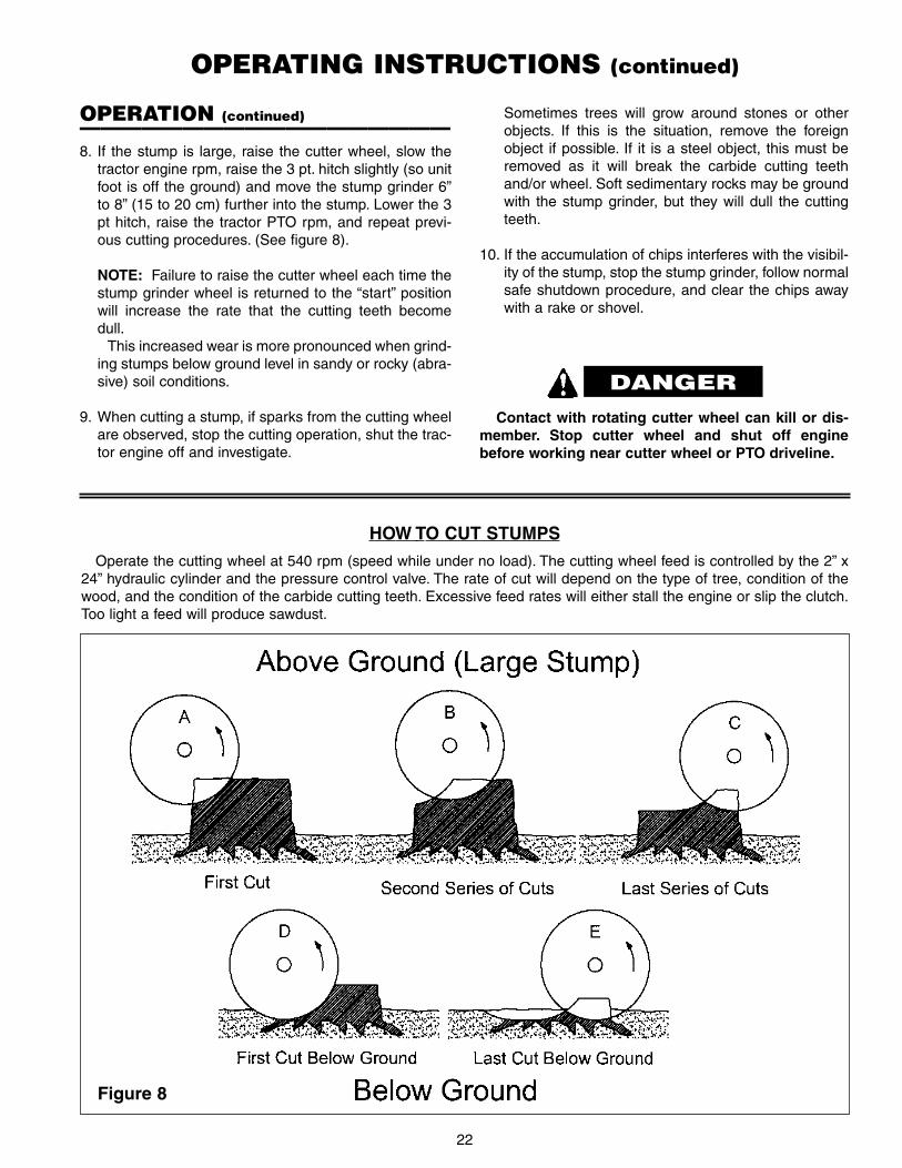
HOW TO CUT STUMPS
Operate the cutting wheel at 540 rpm (speed while under no load). The cutting wheel feed is controlled by the 2” x24” hydraulic cylinder and the pressure control valve. The rate of cut will depend on the type of tree, condition of thewood, and the condition of the carbide cutting teeth. Excessive feed rates will either stall the engine or slip the clutch.Too light a feed will produce sawdust.
Figure 8
OPERATION (continued)——————————————————8. If the stump is large, raise the cutter wheel, slow the
tractor engine rpm, raise the 3 pt. hitch slightly (so unitfoot is off the ground) and move the stump grinder 6”to 8” (15 to 20 cm) further into the stump. Lower the 3pt hitch, raise the tractor PTO rpm, and repeat previ-ous cutting procedures. (See figure 8).
NOTE: Failure to raise the cutter wheel each time thestump grinder wheel is returned to the “start” positionwill increase the rate that the cutting teeth becomedull.
This increased wear is more pronounced when grind-ing stumps below ground level in sandy or rocky (abra-sive) soil conditions.
9. When cutting a stump, if sparks from the cutting wheelare observed, stop the cutting operation, shut the trac-tor engine off and investigate.
DANGER

23
OPERATING INSTRUCTIONS (continued)
OPERATING TIPSDifferent types of stumps (tree variety) will cut different-
ly. (i.e. – a Pine stump will cut different than an Oakstump.) Older stumps where the tree was cut severalyears ago will have “soft” and “hard” areas as the cuttingwheel passes across the stump.
Therefore, when grinding a stump, some stumps will cutfaster and easier than others.
Remember, sharp teeth produce cleaner cuts andrequire less power.
If a stump is a few inches taller than 18 inches, you maybe able to adjust (shorten) your toplink to accommodatethis stump. It is recommended and easier to use a chainsaw to cut the stump to a height of 18 inches or less.
If for some reason, you need to grind a stump to agreater below ground depth, you can adjust (lengthen)your toplink to achieve the desired depth.
Remember, carbide teeth are expensive. The less soilcontact you have with the cutting wheel will result in theteeth remaining sharp for a longer period of time. Cuttingteeth are not a warranty item.
Trees with foreign objects – trees will grow aroundrocks, iron spikes, horseshoes, wire and other things thatare in the ground or put in or against a young growingtree.
Trees that are near where buildings or fence rows areor have been are highly suspect. Always examine thesestumps carefully and when grinding, pay close attentionto the grinding operation.
Contact with imbedded foreign objects will producesparks or a different sound.
If you find a foreign object in a stump that you are grind-ing, try to remove it. Sedimentary stones or rocks canusually be pried out or smashed with an iron bar andhammer. Nails and steel objects need to be removed. Itwill take time and effort, but you can save yourself a newset of carbide cutting teeth.
Raise the cutting wheel before returning to the “START”position. When you have finished a “cutting pass” raisethe cutting wheel slightly before returning to the startposition. Failure to do this will dull the teeth. (This is thesame as why you always raise a file or hand hacksawwhen making your return stroke – dragging the cuttingteeth back over the work piece will dull the teeth).
There are three (3) cutting teeth on the backside of thecutting wheel to protect the wheel those few times thatyou forget to raise it. However, they are not meant to beprimary cutters and should not be treated as such.
STUMP CUTTING
EXTENDING USEFUL LIFE OFCUTTING TEETH
As the cutting teeth become dull they generally performbetter grinding softer woods. When grinding a large num-ber of stumps it is recommended that the hardwoodstumps be cut first when the cutting teeth are theirsharpest. Then proceed to the soft wood stumps. Whenthis method is combined with recommended teeth rota-tion on the wheel, maximum tooth life is achieved.
Figure 9
UP TO 12 INCH DIAMETER STUMPS
These stumps can usually be cut with one tractor posi-tion. Position the stump cutting wheel about centered tothe stump but to the side. Make the cutting passes nec-essary to grind the stump down to the desired depth.
STUMPS GREATER THAN 12 INCHDIAMETER
On larger stumps, it will usually require repositioningthe power unit a few times.
Always start cutting the side of the stump facing thetractor, when this part is cut down 10-12 inches from thetop of the stump, move toward the stump 8-10 inches andrepeat the process. If there is still a portion of the stumpat near original height, move again toward the stump andrepeat the cutting process. (See figure 8.)
If the stump was high or it is desired to cut the stumpto a greater depth, then move back to the beginning posi-tion and repeat the process.
NOTE: Do not cut stumps so that the cutting wheelleaves an uncut portion of the stump between the cuttingwheel and the tractor or skid steer. This portion of thestump can catch the main swing arm of the stump cutterand prevent it from cutting. (See figure 9.)

24
OPERATING INSTRUCTIONS (continued)
CUTTING FEED RATE – PTO MODELSThe cutting feed rate is controlled by the hydraulic pres-
sure relief valve connected to the 2” X 24” hydraulic cylin-der. The pressure relief valve is set from the factory at150 psi. For most tractors and cutting conditions, thisshould be correct.
If your tractor is on the lower end of the recommendedhorsepower range of the stump grinder model, it wouldhelp if you lowered the pressure setting.
If you are cutting very hard wood and have sufficienttractor horsepower, it could help if you increased thepressure setting.
Adjust relief valve only with stump grinder andtractor shut off, then relieve all hydraulic pressure.
Always have the thumb wheel locked securelyagainst the valve body prior to operation. Failure todo so may cause serious personal injury.
• Pay particular close attention to the Safety Messagesregarding cutter transport. Avoid unnecessary injuriesand equipment damage by exercising cautious, con-scientious travel procedures.
• Be sure to reduce power unit ground speed whenturning; and, leave enough clearance so the stumpgrinder does not contact obstacles such as buildings,trees or fences.
• Select a safe ground travel speed when transportingfrom one area to another. When traveling onroadways, transport in such a way that faster movingvehicles may pass you safely.
• Allow for additional length of loader and attachment ontractor while turning.
• When traveling over rough or hilly terrain, slow downand use extra care.
• Read all the safety warnings in the front of the manual.
• DO NOT OPERATE PTO DURING TRANSPORT.
When traveling on public roads, whether at night orduring the day, use accessory light and devices foradequate warnings to operators of other vehicles.Comply with all federal, state and local laws.
TRANSPORTING——————————————————
REMOVING STUMP GRINDERFROM TRACTOR——————————————————
Properly park tractor, shut off engine, and disengagetractor PTO.
Lower and pin parking stand.
Lower stump grinder with 3 pt. hitch. Lower cuttingwheel so parking stand contacts ground.
Shut off power unit engine.
Relieve all hydraulic pressure in hydraulic hose lines.
Disconnect driveline from tractor PTO. Collapse drive-line as far as possible and store it to prevent groundcontact.
Disconnect hydraulic hoses. Cap hose ends to keepthem clean.
Disconnect power unit from stump grinder. Positionhydraulic hoses so they are not contacting the ground.
Carefully drive power unit away.
STORING SAFELY——————————————————• Make sure stump grinder will be located on a solid
surface and in a location away from children, animals,or traffic area.
• Storage location should be level and solid to makehitching and unhitching easy with the grader bladelowered.
• Drain and change the oil in your gearbox.
• Check and replace, where necessary, teeth, bolts,nuts, or bushings, on the machine.
• Replace any safety signs if damaged.
• Sand areas where paint is chipped or worn and repaintto prevent rust. Lubricate all pivot locations on stumpgrinder to prevent moisture damage during storage.
• Place plastic caps on the hydraulic hose ends.
• Cover the unit to keep it clean.
• Coat hydraulic cylinder rods with lithium based grease.
WARNING
CAUTION

25
OWNER SERVICE
The information in this section is written for operatorswho possess basic mechanical skills. Should you needhelp, your dealer has trained service techniciansavailable. For your protection, read and follow all safetyinformation in this manual.
▲▲ Before servicing the machine, disengage the PTO,engage the parking brake or place the transmis-sion in “Park,” shut off the power unit and removethe key. Disconnect stump grinder driveline fromtractor PTO before performing any service ormaintenance.
▲▲ Before working underneath, raise 3 pt. hitch tohighest position and block stump grinder secure-ly. Hydraulic system leakdown and failure ofmechanical or hydraulic system can cause equip-ment to drop.
▲▲ Keep all persons away from operator control areawhile performing adjustments, service or mainte-nance.
Daily lubrication of the PTO slip joint is necessary.Failure to maintain proper lubrication can result indamage to U-joints, gearbox, tractor PTO and/or stumpgrinder driveline.
LUBRICATION CHART
DESCRIPTION FREQUENCY
Front U-Joint (PTO) 8 Hrs.Rear U-Joint (PTO) 8 Hrs.Gearbox – Fill to proper level Check DailySlip Joint (PTO) 8 Hrs.Swing Arm Pivot Joint 8 Hrs.
REPLACING CUTTING TEETH——————————————————
The laminated design of this stump grinder cuttingwheel provides a “pocket” for each cutting tooth. This“pocket” design supports each cutting tooth so it can han-dle the loads encountered in the stump grinding opera-tion.
It is VERY IMPORTANT that when replacing a cuttingtooth the empty “pocket” be checked for any possible dirtaccumulation. ALWAYS make sure that the “pocket” isCLEAN BEFORE inserting a replacement cutting tooth.
If any dirt is in the “pocket” and the tooth installed, it willnot be seated properly and the bolt holding the toothcould come loose. Operating with a loose cutting toothcould result not only in the loss of the tooth, but damageto the “pocket” in the wheel.
When rotating cutting teeth, always clean each toothbefore installing it in its “new” pocket location.
ROUTINE MAINTENANCE——————————————————DAILY CHECKS:
1. Check that all bolts, nuts, and screws are tight.Checking the bolts and nuts on the cutting wheel isparticularly important.
2. Check daily the level of the gearbox oil and top up tothe correct level. Check for gearbox oil leaks. It shouldbe noted that no warranty claim can be submitted on agearbox that has run dry. It is essential that the gear-box is kept correctly filled with gearbox oil.
3. Grease the PTO shaft daily.
4. Check the wear on the cutting teeth. You should keepat least one set of cutting teeth as spares.
5. Check hydraulic hoses. Make sure they are not chafedor pinched. Replace any damaged hose.
6. Check hydraulic hoses and fittings for leaks. Repairany leaks immediately. Never use your hand to checkfor a hydraulic leak when system is under pressure.
7. Replace any worn or damaged parts immediately. Donot use attachment with any damaged parts.
LUBRICATION INFORMATION——————————————————
The chart gives the frequency of lubrication in operat-ing hours, based on normal conditions. Severe or unusu-al conditions may require more frequent lubrication.
Do not let excess grease collect on or around parts,particularly when operating in sandy areas.
Use an SAE 90W gear lube in gearbox.Use a lithium grease of NO. 2 consistency with a MOLY
(molybdenum disulfide) additive for all locations. Be sureto clean fittings thoroughly before attaching grease gun.When applied according to the lubrication chart, onegood pump of most guns is sufficient. Do not over grease.
Thoroughly clean the grease zerks before servicing. Dirtmixed with lubricant will rapidly wear parts and destroybearings. Keep it clean.
WARNING

26
OWNER SERVICE (continued)
G. Screw the slotted nut back on the threads of the gear-box output shaft to keep from losing the nut and toprotect the threads on the shaft.
H. Remove the two bolts holding the PTO clutch assem-bly on the gearbox input shaft. Slide the PTO clutchassembly off the input shaft.
I. Remove bolts and locknuts securing gearbox toframe. Remove gearbox.
DO NOT HAVE ANYONE HOLD THE WHEEL WHENHITTING THE END OF THE PULLER SCREW WITH AHAMMER. The wheel may jump off the shaft andcould cause injury!
ROTATING CUTTING TEETH——————————————————
The cutting teeth on the outer edge and side of the cut-ting wheel do the majority of the work.
It is recommended that when these teeth become dull,that you exchange them with teeth that are located furthertowards the center of the wheel. This will spread the wearamong the teeth and keep the “sharper” teeth in the maincutting area of the wheel.
The number of stumps that can be ground beforereplacing teeth depends on several factors:
a. Any foreign objects contacted?b. Abrasive soil conditions.c. How deep stumps are cut below ground?d. How large are the stumps?e. How dry is the soil? (Dry, hard soil will cause more
wear than moist soil.)
CUTTING WHEEL & GEARBOXREMOVAL——————————————————A. Raise stump grinder using both the hydraulic lift
cylinder and the 3 pt. hitch. Follow normal shutdownprocedure before dismounting from the power unit.
B. Lower the jack stand and pin securely.
C. Lower the tractor 3 pt. hitch first and then the hydrauliclift cylinder so the stump grinder is on the ground orshop floor. This will position the bottom of the wheeljust slightly above ground or floor level.
D. Remove the side shield from the cutter wheel housing.
E. Remove the cotter pin and slotted nut. (Use a largeblock of wood against the edge of the cutting wheel tobreak the slotted nut loose.)
F. Use a good three (3) arm wheel puller to pull the cut-ting wheel off the tapered splined output shaft of thegearbox.
NOTE: Once you have tension on the wheel with thewheel puller, a sharp rap with a hammer will “pop” thewheel off.
CUTTING WHEEL & GEARBOXINSTALLATION——————————————————A. Raise stump grinder using both the hydraulic lift
cylinder and the 3 pt. hitch. Follow normal shutdownprocedure before dismounting from the power unit.
B. Lower the jack stand and pin securely.
C. Lower the tractor 3 pt. hitch first and then the hydrauliclift cylinder so the stump grinder is on the ground orshop floor. This will position the bottom of the wheeljust slightly above ground or floor level.
D. Attach gearbox to frame using bolts and nuts.
E. Install cutting wheel onto gearbox securing withcastellated nut and flat washer. Torque nut to 350ft./lbs. Wear heavy work gloves to protect hands fromsharp edges.
F. Install cotter pin to retain nut. It may be necessary toslightly loosen nut to install cotter pin.
G. Slide PTO clutch assembly on the the gearbox inputshaft. Install the two bolts and tighten.
NOTE: The two bolts need to align with the groove inthe gearbox input shaft. It may require moving thePTO clutch assembly forward or back to get properalignment.
H. Fill gearbox with oil to proper level.
I. Replace the side shield on the cutter wheel housing.Tighten these nuts securely.
WARNING
27
OWNER SERVICE (continued)
The slip clutch is factory preset to the correct torque forprotecting implement and tractor.
Loosen the eight bolts to remove all tension fromsprings (until spring can be turned with fingers).
Hold clutch hub solid and turn shaft to make sure clutchslips.
If clutch does not slip freely, disassemble and clean thefaces of clutch plate, yoke and plate, and clutch hub.
Reassemble clutch.
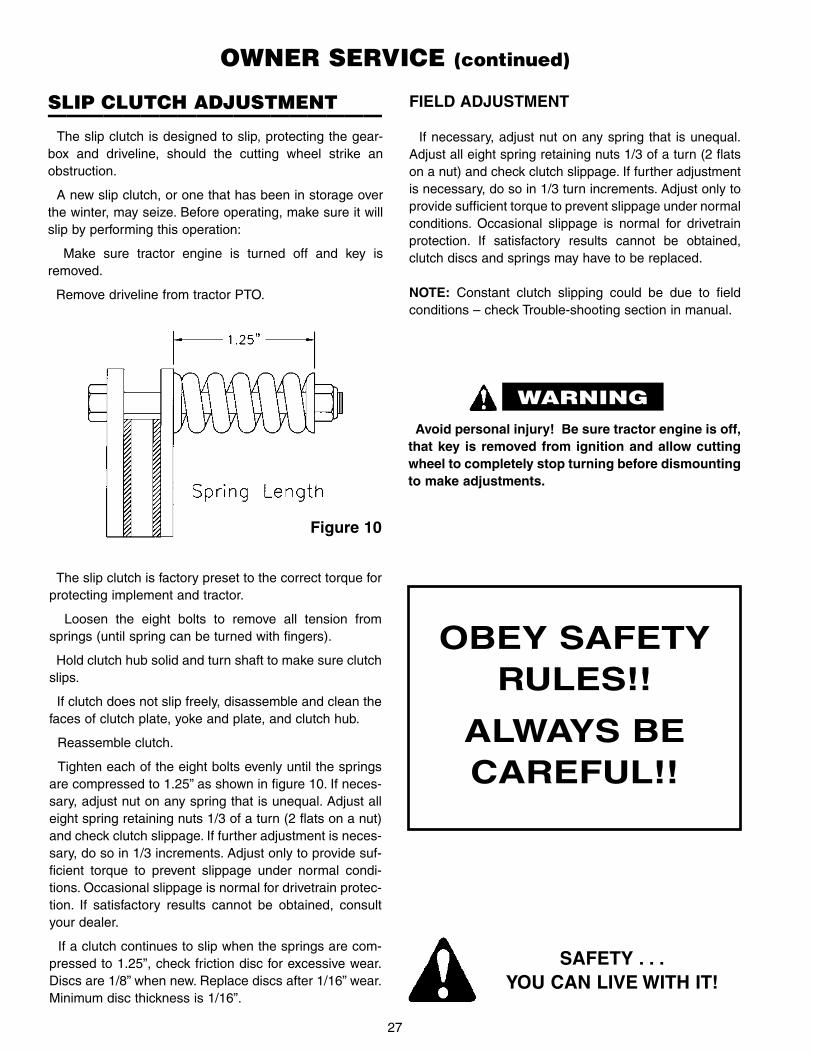
Tighten each of the eight bolts evenly until the springsare compressed to 1.25” as shown in figure 10. If neces-sary, adjust nut on any spring that is unequal. Adjust alleight spring retaining nuts 1/3 of a turn (2 flats on a nut)and check clutch slippage. If further adjustment is neces-sary, do so in 1/3 increments. Adjust only to provide suf-ficient torque to prevent slippage under normal condi-tions. Occasional slippage is normal for drivetrain protec-tion. If satisfactory results cannot be obtained, consultyour dealer.
If a clutch continues to slip when the springs are com-pressed to 1.25”, check friction disc for excessive wear.Discs are 1/8” when new. Replace discs after 1/16” wear.Minimum disc thickness is 1/16”.
Figure 10
FIELD ADJUSTMENT
If necessary, adjust nut on any spring that is unequal.Adjust all eight spring retaining nuts 1/3 of a turn (2 flatson a nut) and check clutch slippage. If further adjustmentis necessary, do so in 1/3 turn increments. Adjust only toprovide sufficient torque to prevent slippage under normalconditions. Occasional slippage is normal for drivetrainprotection. If satisfactory results cannot be obtained,clutch discs and springs may have to be replaced.
NOTE: Constant clutch slipping could be due to fieldconditions – check Trouble-shooting section in manual.
Avoid personal injury! Be sure tractor engine is off,that key is removed from ignition and allow cuttingwheel to completely stop turning before dismountingto make adjustments.
SAFETY . . .YOU CAN LIVE WITH IT!
OBEY SAFETYRULES!!
ALWAYS BECAREFUL!!
SLIP CLUTCH ADJUSTMENT——————————————————
The slip clutch is designed to slip, protecting the gear-box and driveline, should the cutting wheel strike anobstruction.
A new slip clutch, or one that has been in storage overthe winter, may seize. Before operating, make sure it willslip by performing this operation:
Make sure tractor engine is turned off and key isremoved.
Remove driveline from tractor PTO.
WARNING

28
TROUBLE-SHOOTING
PROBLEM POSSIBLE CAUSE POSSIBLE REMEDY
Stump grinder wheelraises during cut
1. Dull teeth.
2. Foreign object in stump.
Rotate or replace teeth.
Check – remove object if possible.
Breaking cutting teeth 1. Contact with stones or other for-eign objects.
Check – remove stones or foreignobject.
Replace broken teeth.
Stump grinder will notgrind stump enoughbelow ground level
1. Toplink needs adjusting. Adjust toplink.
Stump grinder will notgrind high enough
1. Toplink needs adjusting. Adjust toplink.
Stump grinder wheelshows wear
1. Operating too long with dull teeth.
2. Operating below ground level inabrasive soil conditions.
3. Operating wheel with teeth missing.
4. Contact with foreign objects.
Replace or rotate teeth more often.
Do not grind stumps below groundmore than necessary.
Always operate cutting wheel with fullset of cutting teeth. Check wheeloften.
Be more observant when operating.
Tractor stalls 1. Too large of cut.
2. Tractor or skid steer too small.
3. Tractor PTO rpm too low.
4. Too heavy of cut.
5. Teeth dull.
Reduce cut depth or reposition powerunit so wheel only cuts part of stump.
Use larger power unit.
Operate at 540 PTO rpm.
Only apply interrupted hydraulic pres-sure to swing cylinder (let tractorrecover rpm before applying moreside cutting pressure).
Replace teeth.

29
TROUBLE-SHOOTING (continued)
PROBLEM POSSIBLE CAUSE POSSIBLE REMEDY
Teeth wear too fast 1. Cutting in sandy conditions.
2. Cutting in rocky conditions.
3. Operator not raising wheel whenreturning to “start” position.
4. Cutting teeth hitting foreign objectin stump.
5. Operator not rotating teeth.
Don’t grind below ground more thannecessary.
Remove rocks from around stump.
Raise wheel slightly before returningto “start” position (see page 24).
Check stump for wire, iron, spike,horseshoe, etc. Remove.
Rotate teeth.
Stump grinder seems torequire excessive power
1. Advancing into stump too rapidly ortoo great a cut.
2. Worn or dull teeth.
3. Tractor not large enough.
Take less cut or reduce hydraulic feedpressure (see page 27).
Rotate or replace teeth.
Use larger tractor.
Stump grinder movesfrom side to side whencutting
1. Loose tractor sway chains or bars,or sway block improperly installed.
2. Stump grinder not properly latchedon skid steer.
Adjust sway chains, bars, or swayblocks.
Check latches.
Stump grinder will notcut all the time (slipclutch drive)
1. Slip clutch slipping.
2. Tractor PTO clutch slipping.
3. Low hydraulic oil.
4. Teeth dull and stump is hardwood.
5. See – “Stump grinder will not feedinto stump”.
Adjust slip clutch according to instruc-tions.
Check tractor PTO – replace clutch ifnecessary.
Check oil level.
Replace teeth.

30
TROUBLE-SHOOTING (continued)
PROBLEM POSSIBLE CAUSE POSSIBLE REMEDY
Hydraulic hose failure 1. Power unit hydraulic relief pressuresetting is very high and may causehydraulic hose failure.
2. Hoses are worn or frayed.
3. Hose rating may be too low forhydraulic system pressure.
4. Hose is being pinched by move-ment of 3 pt. mount or 3 pt.linkage.
Check power unit hydraulic systemand adjust relief valve.
Replace hose.
Replace with higher rated hoses.
Reroute hose and refasten.
Hydraulic oil overheats 1. Hydraulic oil level in tractor may below.
2. Hydraulic oil or oil filter in tractormay be dirty.
3. Hydraulic oil reservoir of tractormay be small.
4. Tractor has closed center hydraulicsystem.
Check and add oil.
Change oil and filter according topower unit manufacturer’s recommen-dations.
Allow time for oil to cool down.
Flow control should be at minimumflow.
If no flow control, add restrictor orifice(throttle valve) to reduce flow (seepage 22).
Stump grinder wheelwill not feed into stump
1. Too big of a cut.
2. Operator cut rear part of stumpfirst. Front uncut part of stump isholding wheel arm.
3. Teeth very dull.
4. Low hydraulic oil in tractor or trac-tor is on steep hill and oil in reser-voir is away from pump inlet.
5. Quick couplers on swing cylinderhoses not properly engaged (orwrong couplers for tractor remotehydraulic outlets).
6. Relief valve setting too low.
Raise wheel and take less cut.
Raise and reposition stump grinder tocut front part of stump – then go backto rear to cut deeper.
Replace teeth.
Check oil level. Reposition tractor inother direction (if possible).
Check couplers and make sure theyare connected properly.
Check and increase relief valve pres-sure. (Best if checked with pressuregauge.)

31
TROUBLE-SHOOTING (continued)
PROBLEM POSSIBLE CAUSE POSSIBLE REMEDY
Gearbox overheating 1. Low on lubricant.
2. Improper type lubricant.
3. Excessive trash build-up aroundgearbox.
Fill to proper level.
Replace with proper lubricant.
Remove trash.
Gearbox leaking 1. Damaged oil seal.
2. Bent shaft.
3. Shaft rough in oil seal area.
4. Oil seal installed wrong.
5. Oil seal not sealing in the housing.
6. Oil level too high.
7. Hole in gearbox.
8. Gasket damaged.
9. Bolts loose.
Replace seal.
Replace oil seal and shaft.
Replace or repair shaft.
Replace seal.
Replace seal or use a sealant on out-side diameter of seal.
Drain oil to proper level.
Replace gearbox.
Replace gasket.
Tighten bolts.
Excessive vibration 1. Check gearbox bolts.
2. Check for loose nut and cuttingwheel.
3. Check for bent output shaft. Ifshaft is bent, oil will normally leakfrom output seal.
4. Drivelines not phased correctly.Implement and tractor yokes mustbe in line.
5. Wire or rope wrapped around cut-ting wheel.
6. Teeth worn.
7. Teeth missing on wheel.
8. Too heavy cut.
Tighten if loose.
Tighten if loose.
Replace shaft if bent.
Replace driveline.
Remove wire or rope.
Replace teeth.
Check and replace teeth.
Reduce cutting depth or reducehydraulic feed pressure.
Gearbox noisy 1. Rough gears.
2. Worn bearings.
3. Low oil in gearbox.
Run in or change gears.
Replace bearing.
Check level and add oil.

32
SG-26A/SG-36A STUMP GRINDER HYDRAULIC DIAGRAM & PARTS LIST

33
SG-26A STUMP GRINDERPARTS DRAWING

34
SG-26A STUMP GRINDER PARTS LIST
* NOTE: Order811600 for repair kitcontaining (12)twelve carbide teeth,bolts & washers

35
SG-36A STUMP GRINDERPARTS DRAWING

36
SG-36A STUMP GRINDER PARTS LIST
* NOTE: Order811600 for repair kitcontaining (12)twelve carbide teeth,bolts & washers

37
SG-26A GEARBOX PARTS DRAWING & LIST

38
SG-36A GEARBOX PARTS DRAWING & LIST

39
SG-26A PTO SHAFT PARTS DRAWING & LIST

40
SG-36A PTO SHAFT PARTS DRAWING & LIST

WS-SG001-OG
WORKSAVER, INC.P.O. BOX 100 LITCHFIELD, IL 62056-0100 (217) 324-5973
WEB: http://www.worksaver.com E-MAIL: [email protected]
OWNER’S/OPERATOR’S
MANUAL
MODEL NO.’s
SG-26A
SG-36A
WHEN ORDERING REPAIRPARTS, ALWAYS GIVE THE
FOLLOWING INFORMATION:
1. PART NUMBER2. PART DESCRIPTION3. MODEL NUMBER4. NAME OF ITEM
JULY 2021
SAFETY REQUIREMENTSAVOID ACCIDENTS BY FOLLOWING ALL OF THE SAFETY REQUIREMENTS LISTED BELOW.
• Machinery should be operated only by those who areresponsible and are authorized to do so.
• Stop the engine, lower all equipment, lock the brakes,and remove the ignition key before dismounting from thetractor.
• Never stand between tractor and implement while tractoris being backed to hitch.
• Loose fitting clothing should not be worn, to avoid catch-ing on various parts.
• Detach implement in area where children normally do notplay.
• When performing adjustments or maintenance on animplement, first lower it to the ground or block it securelyat a workable height.
• Only a qualified operator should be permitted on tractorwhen in operation; no riders allowed.
• Make certain everyone is in the clear before startingtractor or raising or lowering equipment.
• Operate the tractor and implement only while seated inthe driver’s seat.
• Reduce speed when transporting mounted implementsto avoid bouncing and momentary loss of steeringcontrol.
• A heavy load can cause instability of the tractor. Useextreme care during road travel. Slow down on turns andwatch out for bumps. Tractor may need front counter-weights to counter-balance the weight of the implement.
• Reduce speed on hillsides or curves so there is nodanger of tipping.
• Avoid driving too close to the edge of ditches or creeks.
• Do not transport implement on public roads withoutreflectors and slow moving vehicle emblem in daylightand with approved warning lights at night and otherperiods of poor visibility.
• Due to the width of some implements, use extra cautionon highways, farm roads, and when approaching gates.
• Always be sure the implement is in the proper position fortransport.
• Keep alert and watch the front as well as the rear whenworking with the implement.
Please work, drive, play and live each day withcare and concern for your safety and that of yourfamily and fellow citizens.
STUMP GRINDERSfor
TRACTORS
MAKE EVERY DAYA HOLIDAY
FROM ACCIDENTS


![Kinetix Motion Control_[Gmc-sg001]](https://img.pdfslide.us/doc/110x75/54e65cc24a79594c358b46bd/kinetix-motion-controlgmc-sg001.jpg)