Embed Size (px)
Citation preview
1
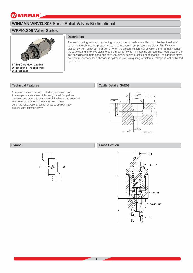
WINMAN WRVI0.S08 Serisi Relief Valves Bi-directional
WRVI0.S08 Valve Series
Technical Features Cavity Details SAE08
Description
Symbol Cross Section
A screw-in, cartrigde style, direct acting, poppet type, normally closed hydraulic bi-directional reliefvalve. It's typically used to protect hydraulic components from pressure transients. The RVI valveblocks flow from either port 1 or port 2. When the pressure differential between ports 1 and 2 reachesthe valve setting, the valve starts to open, throttling flow to minimize the pressure rise, regardless of theinlet flow direction. Both directions have very similar setting pressure performance. The cartridge offersexcellent response to load changes in hydraulic circuits requiring low internal leakage as well as limitedhyseresis.
All external surfaces are zinc plated and corrosion-proof.All valve parts are made of high strength steel. Poppet arehardened and ground to guarantee minimal wear and extendedservice life. Adjustment screw cannot be backedout of the valve.Optional spring ranges to 250 bar (3600psi). Industry common cavity.
SAE08 Cartridge - 250 barDirect acting - Poppet typeBi-directional
1 2
2
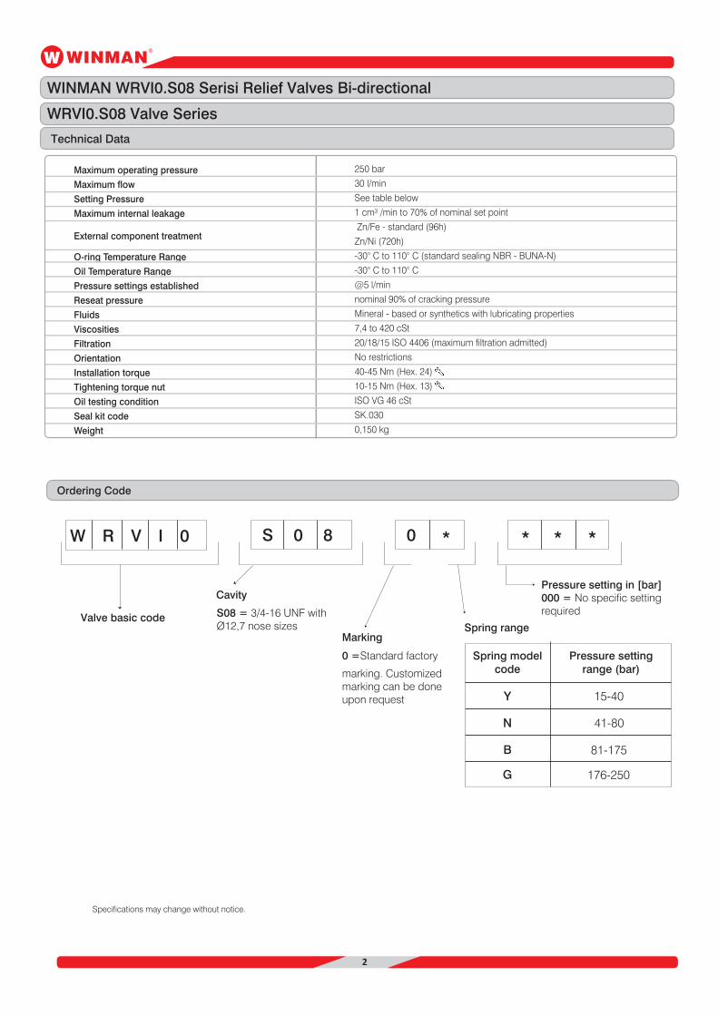
Technical Data
Ordering Code
Maximum operating pressure
Maximum flow
Setting Pressure
Maximum internal leakage
O-ring Temperature Range
Oil Temperature Range
Pressure settings established
Reseat pressure
Fluids
Viscosities
Filtration
Orientation
Installation torque
Tightening torque nut
Oil testing condition
Seal kit code
Weight
External component treatment
250 bar
30 l/min
See table below
1 cm³ /min to 70% of nominal set point
Zn/Fe - standard (96h)
Zn/Ni (720h)
-30° C to 110° C (standard sealing NBR - BUNA-N)
-30° C to 110° C
@5 l/min
nominal 90% of cracking pressure
Mineral - based or synthetics with lubricating properties
7,4 to 420 cSt
20/18/15 ISO 4406 (maximum filtration admitted)
No restrictions
40-45 Nm (Hex. 24)
10-15 Nm (Hex. 13)
ISO VG 46 cSt
SK.030
0,150 kg
Specifications may change without notice.
W R V I 0 S 0 8 0 * * * *
Valve basic code
Cavity
Marking
Pressure setting in [bar]000 = No specific settingrequired
Spring range
Spring modelcode
Pressure settingrange (bar)
0 =Standard factory
marking. Customizedmarking can be doneupon request
S08 = 3/4-16 UNF withØ12,7 nose sizes
Y 15-40
41-80
81-175
176-250
N
B
G
WINMAN WRVI0.S08 Serisi Relief Valves Bi-directional
WRVI0.S08 Valve Series
3
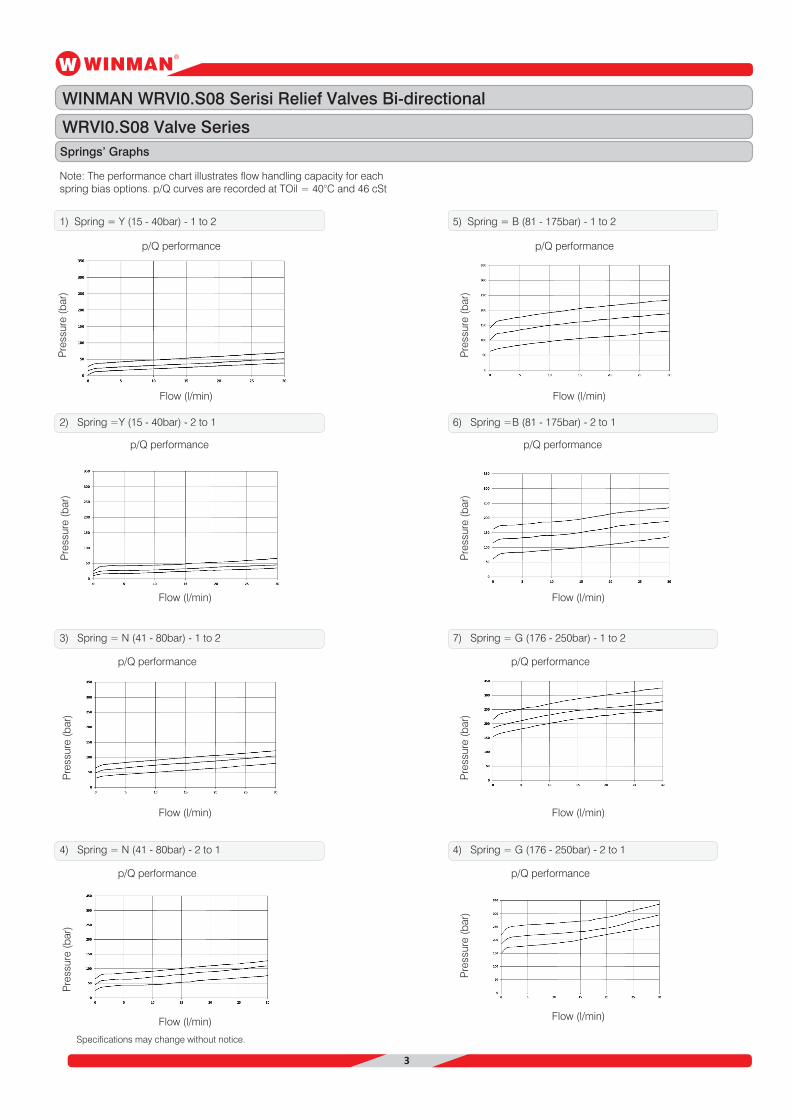
Note: The performance chart illustrates flow handling capacity for eachspring bias options. p/Q curves are recorded at TOil = 40°C and 46 cSt
1) Spring = Y (15 - 40bar) - 1 to 2
2) Spring =Y (15 - 40bar) - 2 to 1
Specifications may change without notice.
p/Q performance
Flow (l/min)
Flow (l/min)
Pre
ssur
e (b
ar)
p/Q performance
Pre
ssur
e (b
ar)
Springs’ Graphs
WINMAN WRVI0.S08 Serisi Relief Valves Bi-directional
WRVI0.S08 Valve Series
3) Spring = N (41 - 80bar) - 1 to 2
Flow (l/min)
p/Q performance
Pre
ssur
e (b
ar)
4) Spring = N (41 - 80bar) - 2 to 1
Flow (l/min)
p/Q performance
Pre
ssur
e (b
ar)
5) Spring = B (81 - 175bar) - 1 to 2
6) Spring =B (81 - 175bar) - 2 to 1
p/Q performance
Flow (l/min)
Flow (l/min)
Pre
ssur
e (b
ar)
p/Q performance
Pre
ssur
e (b
ar)
7) Spring = G (176 - 250bar) - 1 to 2
Flow (l/min)
Flow (l/min)
p/Q performance
Pre
ssur
e (b
ar)
4) Spring = G (176 - 250bar) - 2 to 1
p/Q performance
Pre
ssur
e (b
ar)