Embed Size (px)
Citation preview
Written By : Simon Teo
B. ENG (HONS)
The Ultimate Control Valves Used in Hydronic HVAC System FlowCon International pressure independent flow control valves (SM) are changing the way control valves function and classified in a hydronic HVAC system. It is no more just an ordinary control valve that performed flow modulation in AHU or FCU only. FlowCon SM valves can be classified as a combination of a Control Valve, Automatic balancing valve and also a Flow measuring device. In FlowCon SM valves, the automatic balancing maintains and set a constant DP across the control valve. Looking at the Flow equation, the flow will remain constant of course unless you change the Cv.
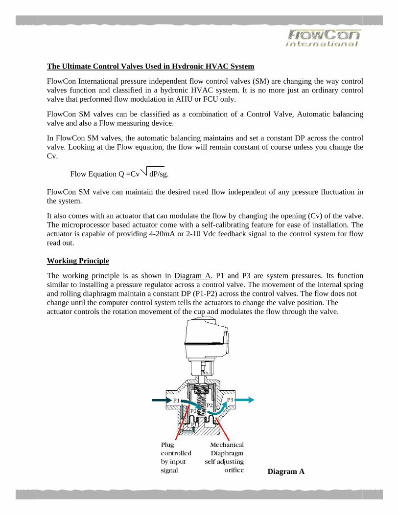
Flow Equation Q =Cv dP/sg. FlowCon SM valve can maintain the desired rated flow independent of any pressure fluctuation in the system. It also comes with an actuator that can modulate the flow by changing the opening (Cv) of the valve. The microprocessor based actuator come with a self-calibrating feature for ease of installation. The actuator is capable of providing 4-20mA or 2-10 Vdc feedback signal to the control system for flow read out. Working Principle The working principle is as shown in Diagram A. P1 and P3 are system pressures. Its function similar to installing a pressure regulator across a control valve. The movement of the internal spring and rolling diaphragm maintain a constant DP (P1-P2) across the control valves. The flow does not change until the computer control system tells the actuators to change the valve position. The actuator controls the rotation movement of the cup and modulates the flow through the valve.
Diagram A
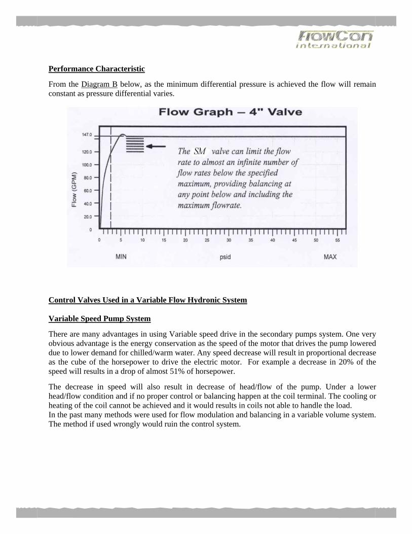
Performance Characteristic From the Diagram B below, as the minimum differential pressure is achieved the flow will remain constant as pressure differential varies.
Control Valves Used in a Variable Flow Hydronic System Variable Speed Pump System There are many advantages in using Variable speed drive in the secondary pumps system. One very obvious advantage is the energy conservation as the speed of the motor that drives the pump lowered due to lower demand for chilled/warm water. Any speed decrease will result in proportional decrease as the cube of the horsepower to drive the electric motor. For example a decrease in 20% of the speed will results in a drop of almost 51% of horsepower. The decrease in speed will also result in decrease of head/flow of the pump. Under a lower head/flow condition and if no proper control or balancing happen at the coil terminal. The cooling or heating of the coil cannot be achieved and it would results in coils not able to handle the load. In the past many methods were used for flow modulation and balancing in a variable volume system. The method if used wrongly would ruin the control system.
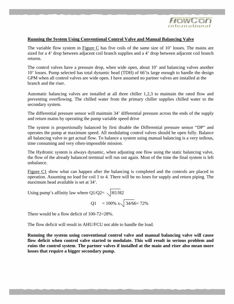
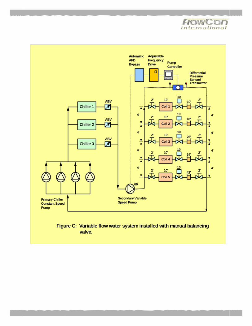
Running the System Using Conventional Control Valve and Manual Balancing Valve The variable flow system in Figure C has five coils of the same size of 10’ losses. The mains are sized for a 4’ drop between adjacent coil branch supplies and a 4’ drop between adjacent coil branch returns. The control valves have a pressure drop, when wide open, about 10’ and balancing valves another 10’ losses. Pump selected has total dynamic head (TDH) of 66’is large enough to handle the design GPM when all control valves are wide open. I have assumed no partner valves are installed at the branch and the riser. Automatic balancing valves are installed at all three chiller 1,2,3 to maintain the rated flow and preventing overflowing. The chilled water from the primary chiller supplies chilled water to the secondary system. The differential pressure sensor will maintain 34’ differential pressure across the ends of the supply and return mains by operating the pump variable speed drive The system is proportionally balanced by first disable the Differential pressure sensor “DP” and operates the pump at maximum speed. All modulating control valves should be open fully. Balance all balancing valve to get actual flow. To balance a system using manual balancing is a very tedious, time consuming and very often-impossible mission. The Hydronic system is always dynamic, when adjusting one flow using the static balancing valve, the flow of the already balanced terminal will run out again. Most of the time the final system is left unbalance. Figure C1 show what can happen after the balancing is completed and the controls are placed in operation. Assuming no load for coil 1 to 4. There will be no loses for supply and return piping. The maximum head available is set at 34’. Using pump’s affinity law where Q1/Q2= H1/H2
Q1 = 100% x 34/66= 72% There would be a flow deficit of 100-72=28%. The flow deficit will result in AHU/FCU not able to handle the load. Running the system using conventional control valve and manual balancing valve will cause flow deficit when control valve started to modulate. This will result in serious problem and ruins the control system. The partner valves if installed at the main and riser also mean more losses that require a bigger secondary pump.
Chiller 1
Chiller 2
Chiller 3
ABV
ABV
ABV
Primary ChillerConstant SpeedPump
Secondary VariableSpeed Pump
DifferentialPressureSensor/Transmitter
AutomaticAFDBypass
AdjustableFrequencyDrive Pump
Controller
4'
4'
4'
4'
4'
4'
4'
4'
66'
2'
Coil 1
10'2'10'
10'
2'
Coil 3
10'2'10'
26'
2'
Coil 4
10'2'10'
34'
2'
Coil 5
10'2'10'
42'
2'
Coil 2
10'2'10'
18'
Figure C: Variable flow water system installed with manual balancing valve.

Chiller 1
Chiller 2
Chiller 3
ABV
ABV
ABV
Primary ChillerConstant SpeedPump
Secondary VariableSpeed Pump
DifferentialPressureSensor/Transmitter
AutomaticAFDBypass
AdjustableFrequencyDrive Pump
Controller
0'
0'
0'
0'
0'
0'
0'
0'
34'
0'
Coil 3
0'0'34'
0'
0'
Coil 4
0'0'34'
0'
1'
Coil 5
4.5’1'4.5’
23'
0'
Coil 2
0'0'34'
0'
Figure C1: System has flow deficit during operation
0'
Coil 1
0'0'34'
0'
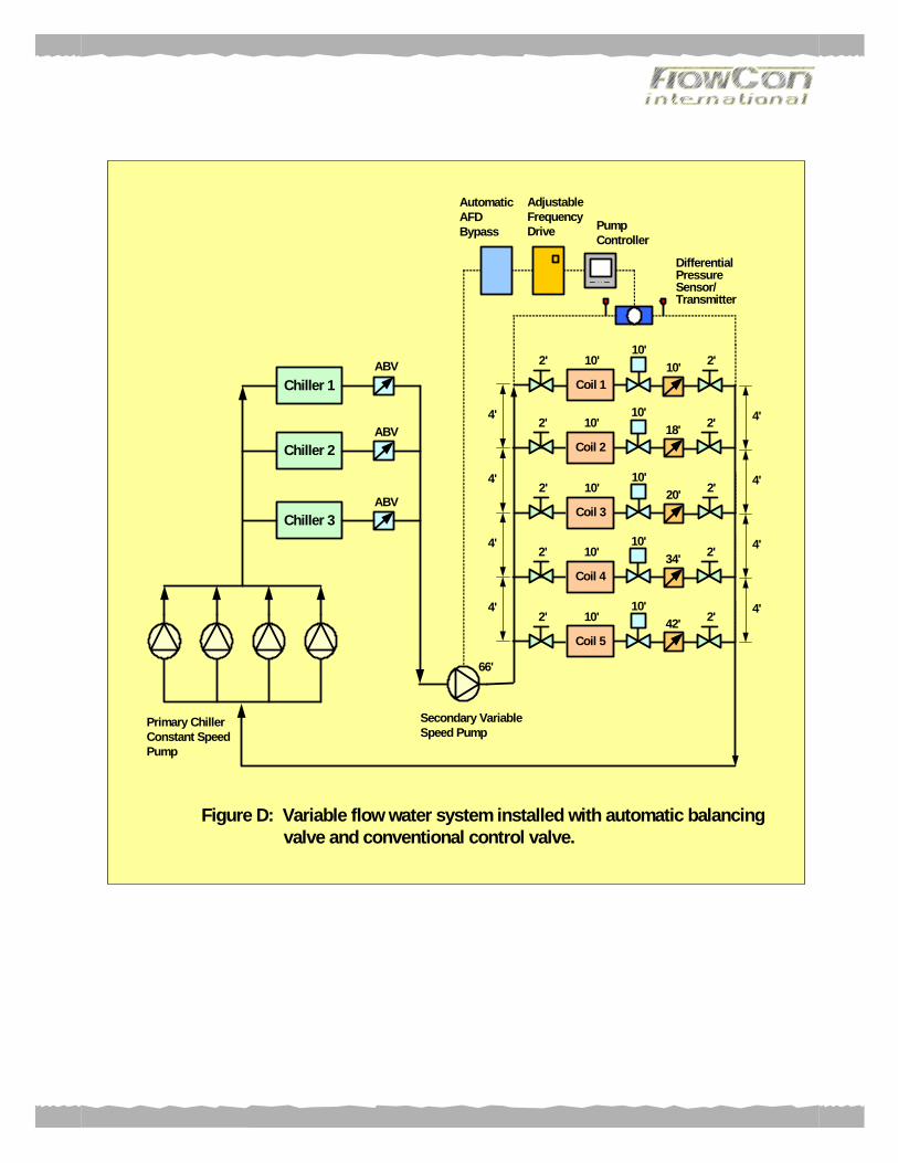
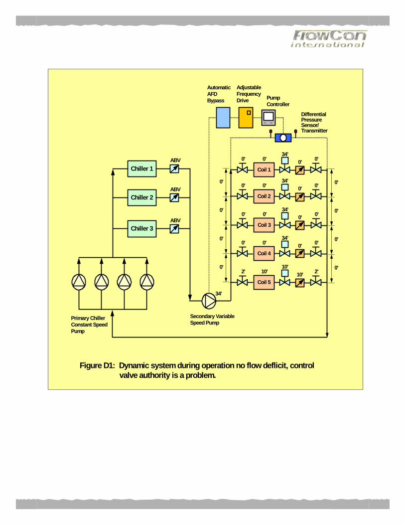
Variable Flow System that control by Using Conventional Control Valve and Automatic Balancing Valve Figure D shows the Manual static Balancing Valve replaced with Automatic Balancing Valves. Both has same loses. With this type of system, less effort is required during start up and commissioning. Basically the system balance by itself. The cartridge in the balancing valve is self-adjusting and it works by changing the Cv value of the valve as the pressure fluctuated to maintain flow. No flow deficit is expected at any time during the operation. Figure D1 show what would happen when there is no load for coil 1 to 4. Similar to system with manual balancing there will be no loses for supply and return piping. The maximum head available for coil 5 is 34’.At this point the losses of the automatic balancing valves would drop tremendously from originally 52’ to 10’. There would be no flow deficit at the coil. The coil would be operating under rated flow to give best efficient cooling. The only problem related to this type of design is with the selection of the control valve. When the selected control valve is too small, it will not satisfy the maximum flow requirement. Too large a valve will provide the maximum needed flow when it is only partially open. The problem is that only a portion of the range of the valves will be utilized, and the smallest change of the opening of the valves will have a too large an effect which makes it hard to accomplish stable control. Therefore valves sizes should be carefully calculated, so the valves pass no more than the desire flow at the available differential pressure. To size the correct control valve extensive pressure differential calculations are needed to find the Cv value of control valve. Pressure differential calculation for every circuit, must be perfect to ensure that the correct Cv valve will allows the control valve to provide correct resistance for design flow. In reality, the selected control valve normally has a Cv value higher than the calculated Cv Value does. The Valve Authority (VA) is define as the ratio of Differentiate pressure of the control valve when it is fully open (DP Min) Differentiate pressure of the control valve when it is fully close (DP Max) Looking at Figure D the calculated Valve Authority for coils 1 & 5 are as follow:
VA coil 1= 10/34 =29% VA coil 5= 10/66 =15% In most cases a bigger size control valves are normally selected. A bigger Cv control valve would have lower losses. Let us assume the new selected control valve has losses of 8’.
VA coil 1= 8/32 =25% VA coil 5= 8/64 =12% The oversized control valve will magnify the valve authority problem, which results in hunting of the conventional control valve. The consequences of hunting are shortening actuator and seat life expectancy. More hunting also means decrease occupant comfort. An oversized control valve cost more, may require a larger and more expensive actuator, and have a larger leakage and low close off pressure.
Chiller 1
Chiller 2
Chiller 3
ABV
ABV
ABV
Primary ChillerConstant SpeedPump
Secondary VariableSpeed Pump
DifferentialPressureSensor/Transmitter
AutomaticAFDBypass
AdjustableFrequencyDrive Pump
Controller
4'
4'
4'
4'
4'
4'
4'
4'
66'
2'
Coil 1
10'2'10'
10'
2'
Coil 3
10'2'10'
20'
2'
Coil 4
10'2'10'
34'
2'
Coil 5
10'2'10'
42'
2'
Coil 2
10'2'10'
18'
Figure D: Variable flow water system installed with automatic balancing valve and conventional control valve.
Chiller 1
Chiller 2
Chiller 3
ABV
ABV
ABV
Primary ChillerConstant SpeedPump
Secondary VariableSpeed Pump
DifferentialPressureSensor/Transmitter
AutomaticAFDBypass
AdjustableFrequencyDrive Pump
Controller
0'
0'
0'
0'
0'
0'
0'
0'
34'
0'
Coil 1
0'0'34'
0'
0'
Coil 4
0'0'34'
0'
2'
Coil 5
10'2'10'
10'
0'
Coil 3
0'0'34'
0'
0'
Coil 2
0'0'34'
0'
Figure D1: Dynamic system during operation no flow deflicit, control valve authority is a problem.
Variable Flow System that control by Using Flowcon SM Control Valve The FlowCon SM control valves works effectively in both the fixed speed and the variable speed pump system. Figure E show a typical primary-secondary pump system, where FlowCon SM pressure independent automatic balance modulating control valve were installed for ultimate energy saving and control. Here the SM valve function as a modulating control valve for precise temperature controls and also automatic balancing valve. The SM valve selected has a pressure drop of about 35kPa, this pressure drop will be less than a conventional control valves in combination with balancing valves. Above all no partner balancing is required at the branch and risers. This eliminates unnecessary valves with big losses at the branch and risers if conventional control valves and manual balancing are used. This result in a system with lower totals losses (10% - 40% lower heads). A smaller secondary variable speed pump and smaller piping can be selected. Pump selected has a head of 60’ compare to 66’ for the other design. A smaller motor is needed to drive the secondary pump, end up huge saving in utility bill. This type of system can quickly pay for themselves with savings in energy and power. The selection of valve does not require any Cv calculation. This type of valve only depends on flow and pipe size for valve selection. FlowCon SM valves used in a Dynamic Variable Speed Pump System results in energy saving. Also it lower the initial system cost due to smaller pumps, smaller piping and lesser total valve involved. The saving could be as much as 20% to 30% of the total cost for pumps, piping and valves.
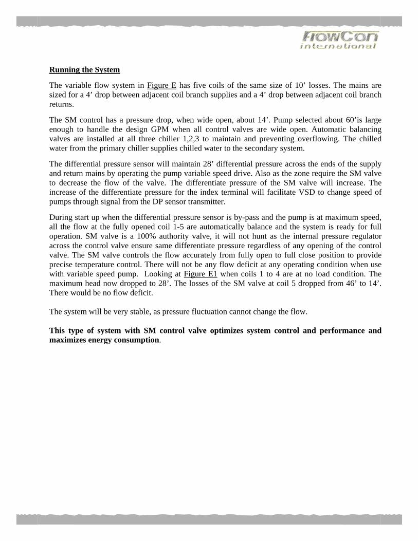
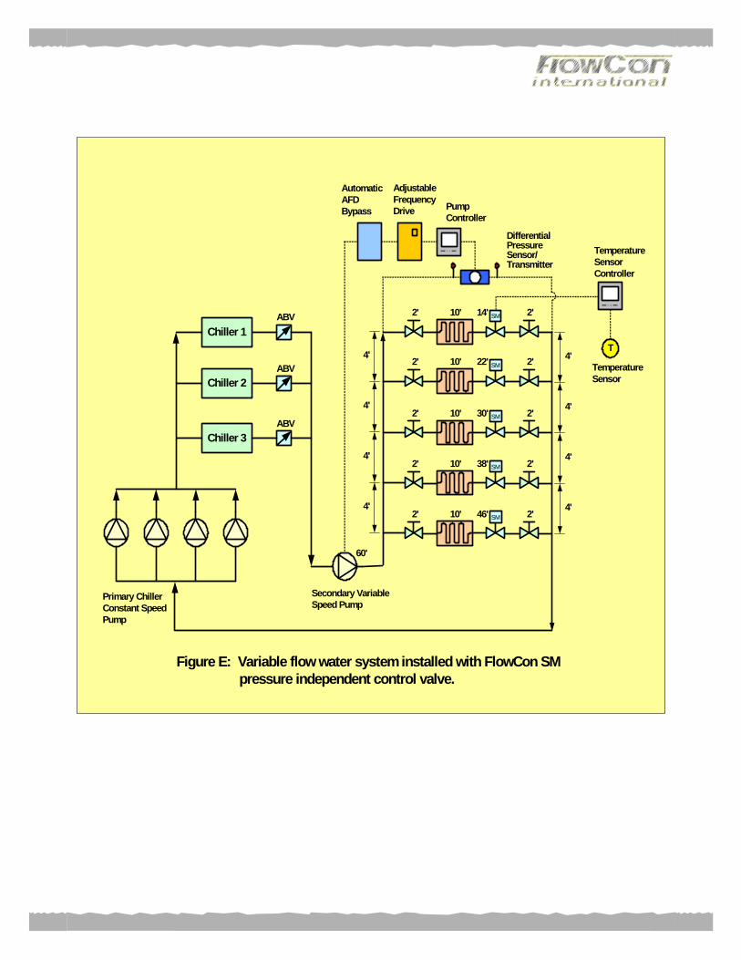
Running the System The variable flow system in Figure E has five coils of the same size of 10’ losses. The mains are sized for a 4’ drop between adjacent coil branch supplies and a 4’ drop between adjacent coil branch returns. The SM control has a pressure drop, when wide open, about 14’. Pump selected about 60’is large enough to handle the design GPM when all control valves are wide open. Automatic balancing valves are installed at all three chiller 1,2,3 to maintain and preventing overflowing. The chilled water from the primary chiller supplies chilled water to the secondary system. The differential pressure sensor will maintain 28’ differential pressure across the ends of the supply and return mains by operating the pump variable speed drive. Also as the zone require the SM valve to decrease the flow of the valve. The differentiate pressure of the SM valve will increase. The increase of the differentiate pressure for the index terminal will facilitate VSD to change speed of pumps through signal from the DP sensor transmitter. During start up when the differential pressure sensor is by-pass and the pump is at maximum speed, all the flow at the fully opened coil 1-5 are automatically balance and the system is ready for full operation. SM valve is a 100% authority valve, it will not hunt as the internal pressure regulator across the control valve ensure same differentiate pressure regardless of any opening of the control valve. The SM valve controls the flow accurately from fully open to full close position to provide precise temperature control. There will not be any flow deficit at any operating condition when use with variable speed pump. Looking at Figure E1 when coils 1 to 4 are at no load condition. The maximum head now dropped to 28’. The losses of the SM valve at coil 5 dropped from 46’ to 14’. There would be no flow deficit. The system will be very stable, as pressure fluctuation cannot change the flow. This type of system with SM control valve optimizes system control and performance and maximizes energy consumption.
SM
SM
SM
SM
SM
Chiller 1
Chiller 2
Chiller 3
ABV
ABV
ABV
T
TemperatureSensorController
TemperatureSensor
Primary ChillerConstant SpeedPump
Secondary VariableSpeed Pump
DifferentialPressureSensor/Transmitter
AutomaticAFDBypass
AdjustableFrequencyDrive Pump
Controller
4'
4'
4'
4'
4'
4'
4'
4'
2' 10' 14' 2'
2' 10' 22' 2'
2' 10' 30' 2'
2' 10' 38' 2'
2' 10' 46' 2'
60'
Figure E: Variable flow water system installed with FlowCon SM pressure independent control valve.
Coil 1SM
Coil 5SM
Chiller 1
Chiller 2
Chiller 3
ABV
ABV
ABV
T
TemperatureSensorController
TemperatureSensor
Primary ChillerConstant SpeedPump
Secondary VariableSpeed Pump
DifferentialPressureSensor/Transmitter
AutomaticAFDBypass
AdjustableFrequencyDrive Pump
Controller
0'
0'
0'
0'
0'
0'
0'
0'
0' 0' 28' 0'
2' 10' 14' 2'
28'
Figure E1: Dynamic system during operation - perfect system with no flow deficit and valve authority problem.
0' 0' 28' 0'
0' 0' 28' 0'
Coil 2SM
Coil 3SM
Coil 4SM0' 0' 28' 0'
SM
TTemperatureSensorController
TemperatureSensor
Centrifugal Fan
Air Inlet Air Outlet
Supp
ly M
ain
Ret
urn
Mai
n
IsolationValve
Coil
SMControlValve
IsolationValve
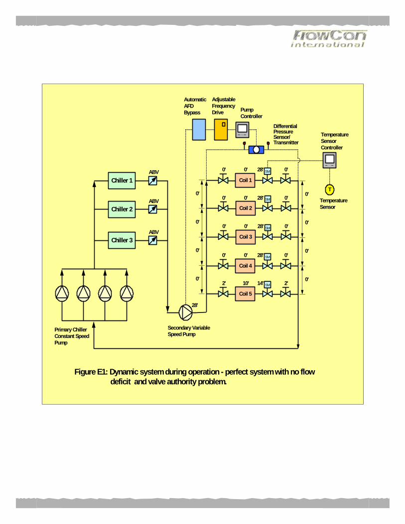
Figure E2: Typical arrangem ent of terminal with FlowCon SM
Conclusion From the finding, I concluded the type of balancing and control valves selected will affect the performance of a variable speed Hydronic HVAC system. Using manual balancing valve has balancing and flow problem that lead to coil under performing. Automatic balancing valve solved most of the flow deficit problem. The system using this method will work only if the control valves are sized properly and the actuators are large enough to position the valve plugs properly. There is a saying that one does not need any balancing valve for flow control. This statement is grossly wrong, as the system will not be balance. All the problems that were discussed regarding valve authority due to valve over-sizing of a conventional control valve would apply. The system using only control valve will not be steady as when one control valve start to modulate the rest of control valves will also start to move too, as the pressure in the system changes. Eventually the system will start to hunt until the right temperature is achieved. The ultimate solution for all the above would still be using the state of art Flowcon SM Pressure Independent Modulating Control Valves.