Embed Size (px)
Citation preview
This journal is©The Royal Society of Chemistry 2016 Soft Matter
Cite this:DOI: 10.1039/c6sm00228e
Wrinkling of structured thin films via contrastedmaterials†
Dong Yan, Kai Zhang* and Gengkai Hu
Regular surface patterns induced by the wrinkling of thin films have received intense attention in both
science and engineering. We investigate the wrinkling of structured thin films that consist of two types
of materials arranged in periodic patterns. A mechanical model is proposed to understand the physics of
the wrinkling, and a set of scaling laws for the wrinkle wavelength are obtained. Periodic wrinkles are
generated in the local regions of structured films via in-plane contrasted elastic modulus between
heterogeneous materials. The wrinkle morphology and location can be tailored by designing structured
thin films in a controllable way. Our findings provide the basis for understanding the wrinkling of
structured thin films and for the manufacture of regular surface patterns via wrinkling.
Introduction
Wrinkling induced by instability of thin films has received intenseattention in recent years owing to its important applications inflexible electronics,1,2 material science,3–6 metrology,7,8 biomedicalengineering9–13 and aerospace engineering.14,15 There is also con-siderable interest in understanding the fundamental aspects ofwrinkling,16–24 including the wavelength and amplitude of wrinklesand the transition of wrinkle patterns. Most studies of the wrinklingonly consider uniform films, no matter whether they are free-standing or bonded to a compliant substrate.12,23–26 In fact, hetero-geneous films widely exist in nature and engineering,1–6,11–15,27–30
and the in-plane heterogeneous characteristics have an importantrole in determining the surface pattern of wrinkles on a film.31–34
Recently, the wrinkling behaviors in patterned porous films andheterogeneous films have also been studied.3–6,16–19 A simplemethod for studying the wrinkling of thin heterogeneous film isto stretch the film with clamped boundaries. It is reported thatwrinkling of the film under stretching arises because the clampedstiff boundaries prevent the film from contracting laterally via thePoisson effect of the whole film.12,23,25 However, boundaries of localregions of the film are also able to be constrained when the film ismade up of different types of materials with contrasted in-planeelastic modulus. The physics of the wrinkling via the contrastedin-plane elastic modulus remains a challenge, and a method ofgenerating controllable periodic patterns on the surfaces ofthin heterogeneous films is also demanded. In this study, we
investigate the wrinkling of heterogeneous films both experimentallyand through numerical simulation and further reveal the underlyingphysics of wrinkling by developing a theoretical model, and bytailoring wrinkle morphology in a controllable way.
Experimental approach
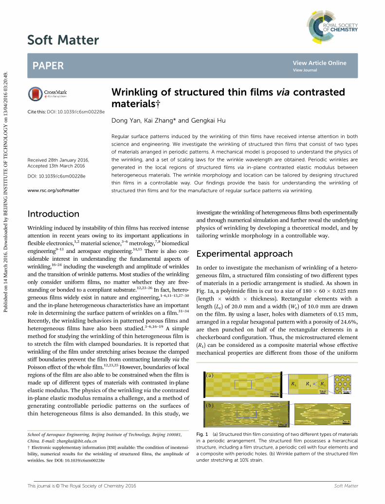
In order to investigate the mechanism of wrinkling of a hetero-geneous film, a structured film consisting of two different typesof materials in a periodic arrangement is studied. As shown inFig. 1a, a polyimide film is cut to a size of 180 � 60 � 0.025 mm(length � width � thickness). Rectangular elements with alength (Le) of 20.0 mm and a width (We) of 10.0 mm are drawnon the film. By using a laser, holes with diameters of 0.15 mm,arranged in a regular hexagonal pattern with a porosity of 24.6%,are then punched on half of the rectangular elements in acheckerboard configuration. Thus, the microstructured element(R1) can be considered as a composite material whose effectivemechanical properties are different from those of the uniform
Fig. 1 (a) Structured thin film consisting of two different types of materialsin a periodic arrangement. The structured film possesses a hierarchicalstructure, including a film structure, a periodic cell with four elements anda composite with periodic holes. (b) Wrinkle pattern of the structured filmunder stretching at 10% strain.
School of Aerospace Engineering, Beijing Institute of Technology, Beijing 100081,
China. E-mail: [email protected]
† Electronic supplementary information (ESI) available: The condition of inextensi-bility, numerical results for the wrinkling of structured films, the amplitude ofwrinkles. See DOI: 10.1039/c6sm00228e
Received 28th January 2016,Accepted 13th March 2016
DOI: 10.1039/c6sm00228e
www.rsc.org/softmatter
Soft Matter
PAPER
Publ
ishe
d on
14
Mar
ch 2
016.
Dow
nloa
ded
by B
EIJ
ING
IN
STIT
UT
E O
F T
EC
HN
OL
OG
Y o
n 13
/04/
2016
03:
20:4
9.
View Article OnlineView Journal
Soft Matter This journal is©The Royal Society of Chemistry 2016
polyimide film. The structured film thus possesses a hierarchicalstructure, including a film structure, a periodic cell with fourelements and a composite with periodic holes, as shown inFig. 1a. The elastic modulus (E2) of the uniform polyimide film ismeasured to be 2.88 � 0.11 GPa by tensile testing, whereas thecomposite material with periodic holes has an effective elasticmodulus (E1) of 1.44 GPa, calculated by the finite elementmethod (FEM). Poisson ratios (n) for both materials are assumedto be 0.31 according to ref. 15. Then, the ends of the film areclamped with aluminum plates and stretched by the tensilemachine (MTS, Eden Prairie, MN, USA) with a strain rate of2% min�1. Two lamps are placed in front of the film with anangle of about 451 or �451 to the normal of the film. A digitalcamera perpendicular to the film is used to capture the imagesof the film during stretching as shown in Fig. 1b.
Results and discussionQualitative observations
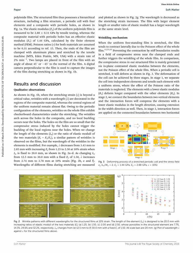
As shown in Fig. 1b, when the stretching strain (e) is beyond acritical value, wrinkles with a wavelength (l) are decorated in theregions of the composite material, whereas the central regions ofthe uniform material remain almost flat. Owing to the periodicconfiguration of the elements, wrinkles on the whole film exhibitcheckerboard characteristics under the stretching. The wrinklesarch across the holes in the composite, and no local bucklingoccurs near the holes. The holes on the film are so small that thecompressive stress induced by the holes cannot trigger thebuckling of the local regions near the holes. When we changethe length of the elements (Le) or the ratio of elastic moduli ofthe two materials (Er = E2/E1), a similar pattern of wrinkles isobserved on the films, but the wavelength of the wrinkles in theelements is modified. For example, l decreases from 3.43 mm to2.85 mm with increasing Er from 1.25 to 2.50 at 10% strain whenLe is fixed to 20.0 mm, as shown in Fig. 2a–d. As changing Le
from 12.5 mm to 30.0 mm with a fixed Er of 1.50, l increasesfrom 2.74 mm to 3.78 mm at 10% strain (Fig. 2b, e and f).Wavelengths of different films during stretching are measured
and plotted as shown in Fig. 2g. The wavelength is decreased asthe stretching strain increases. The film with larger elementlength or smaller ratio of elastic moduli has a larger wavelengthat the same strain level.
Wrinkling mechanism
When the uniform free-standing film is stretched, the filmtends to contract laterally due to the Poisson effect of the wholefilm.12,23,25 Preventing the contraction by stiff boundaries resultsin a field of compressive stress near the clamped ends andfurther triggers the wrinkling of the whole film. In comparison,the compressive stress in our structured film is mainly generatedvia in-plane contrasted elastic modulus between the elements,not the Poisson effect of the whole film. When a periodic cell isstretched, it will deform as shown in Fig. 3. The deformation ofthe cell can be achieved by three stages. In stage 1, we separatethe cell into independent elements and tensile each element witha uniform stress, where the effect of the Poisson ratio of thematerials is neglected. The elements with a lower elastic modulus(R1) deform longer compared with the other elements (R2). Instage 2, we connect the boundaries between two vertical elementsand the interaction forces will compress the elements with alower elastic modulus in the length direction, causing extensionin the width direction as well. Then, in stage 3, interaction forcesare applied on the connected boundaries between two horizontal
Fig. 2 Wrinkle patterns with different wavelengths for the structured films at 10% strain. The length of the element (Le) is designed to be 20.0 mm withincreasing ratios of elastic moduli of the two materials (Er) (a) 1.25, (b) 1.50, (c) 2.00 and (d) 2.50, whose porosities in the structured element are 7.7%,14.3%, 24.6% and 32.2%, respectively. Le changes from (e) 12.5 mm to (f) 30.0 mm with a fixed Er of 1.50. All scale bars are 20 mm. (g) Plot of wavelength lagainst e for the structured films above.
Fig. 3 Deforming process of a stretched periodic cell and the stress fieldsy (Le/We = 2, E1 = 1.44 GPa, E2 = 2.88 GPa, e = 10%).
Paper Soft Matter
Publ
ishe
d on
14
Mar
ch 2
016.
Dow
nloa
ded
by B
EIJ
ING
IN
STIT
UT
E O
F T
EC
HN
OL
OG
Y o
n 13
/04/
2016
03:
20:4
9.
View Article Online

This journal is©The Royal Society of Chemistry 2016 Soft Matter
elements, leading to the compression in the width direction onthe elements with lower elastic modulus. Thus, the element withlower elastic modulus (E1) is under compression generated bythe constraint from adjacent elements with contrasted elasticmodulus, resulting in further wrinkling over a critical strain. Onthe other hand, tensile stress is generated in the element withhigh elastic modulus (E2), preventing the formation of thewrinkles. The structured film under stretching finally displaysperiodic wrinkles with the same pattern as the elements.
Wrinkle characteristics
To characterize the wrinkles of the structured film, we proposea nonlinear mechanical model to describe the behavior ofwrinkling. The periodic cell consisting of four elements(2Le � 2We, Le/We 4 1) is chosen, as shown in Fig. 1. The twotypes of elements in the cell, corresponding to the two regionsR1 and R2, have different elastic moduli, E1 and E2 (E2 4 E1),and the same Poisson ratio, n = n1 = n2, respectively. Now weconsider the energy in the two regions. The total energy inregion R1 or R2 consists of bending and stretching energies. Itcan be seen from Fig. 1b that most of the serious wrinkles aredistributed in R1, whereas they have been drastically weakenedin R2. The bending energy, which relates to the curvature in thewidth direction, is therefore much larger in R1 than in R2.Conversely, the stretching energy, which contributes to thegradient of out-of-plane displacement in the length direction,is larger in R2 than in R1. We have proved numerically that thebending energy of the film in R1 and the stretching energy ofthe film in R2 are dominant in the total energy when the valueof Le/We multiplied by Er is less than or equal to 5. Thus, onlythe bending energy, U1, in R1 and the stretching energy, U2, inR2 are considered. According to previous studies,12,23,34 thebending energy, U1, in R1 can be estimated by
U1 �E1t
3
1� n2ð ÞA
l2
� �2
LeWe; (1)
where l and A are the wavelength and amplitude of thewrinkles, respectively, and t is the thickness of the film. Thestretching energy, U2, in R2 can be estimated by
U2 � T2A
Le
� �2
LeWe; (2)
where T2 is the tension in R2. The strain in the two regions isassumed to be uniform and equal to the applied tensile strain,e. Thus, T2 in R2 is expressed as E2et. As wrinkles are triggereddue to the in-plane mismatch of elastic modulus, it satisfies thecondition of inextensibility in the width direction as (see ESI†)
A
l
� �2
� Er Er � 1ð ÞEr þ 1ð Þ2
Le
We
� �e: (3)
As a consequence, the bending energy in R1 (U1 p l�2) tends tofavor a large wavelength, whereas the stretching energy in R2
(U2 p l2) is minimized when the wavelength vanishes. Thecompetition between the two energies will result in wrinkling.The optimal wavelength is determined by the minimization
of the total energy of the periodic cell, q(U1 + U2)/ql = 0,which gives
l B (1 �n2)�14Er�1
4Le12t
12e�
14. (4)
From the scaling law, the wavelength of wrinkles on thestructured film depends not only on the dimensions of theelements and the stretching strain but also on the materialproperties, especially the ratio of the elastic moduli of the twomaterials. The interaction between the materials with a contrastedin-plane elastic modulus determines the wrinkle pattern andlocation. A larger ratio of Er will lead to a smaller wavelength ofthe wrinkles. Periodic wrinkles can be distributed in the localregions of a film whose wavelength is much smaller than the sizeof the whole film. Thus, wrinkles with a small wavelength can beachieved in desired local regions by designing the elastic moduliof materials in a controllable way. Substituting the expression of linto eqn (3), the amplitude of wrinkles is obtained (see ESI†), butthe accuracy of the scaling law for the amplitude of wrinkles islimited. Our scaling law is also suitable for the wrinkled films withcompliant boundaries. Previous reports by Cerda et al.12,23 showedthat the wrinkle wavelength and amplitude of the clampeduniform film, distributed across the whole uniform film, haveno relation to the elastic modulus of the material. When thetwo materials of the film have the same mechanical properties,periodic wrinkles in the local regions disappear since the amplitudeequals zero (see ESI†), and the wrinkles across the whole film arise,whose wrinkle pattern is governed by the scaling law for uniformfilms.12,23
To verify the scaling law we proposed, we measure thewavelengths of wrinkles at different strains experimentally (Fig. 2g)and plot the dimensionless wavelength l0 = l(1 � n2)
14Er
14Le�1
2t�12
as a function of e�14. As shown in Fig. 4, the data show a linear
relationship with e�14, proving the accuracy of our theoretical
scaling law for wavelength. We fit the data by linear function andobtain a constant 2.82 as the prefactor.
Fig. 4 Plot of the dimensionless wavelength l0 = l(1 � n2)14Er
14Le�1
2t�12 against
e�14 for the structured films in experiment (Fig. 2). The applied tensile strain
is up to 20%. Full line: scaling law l0 = 2.82e�14.
Soft Matter Paper
Publ
ishe
d on
14
Mar
ch 2
016.
Dow
nloa
ded
by B
EIJ
ING
IN
STIT
UT
E O
F T
EC
HN
OL
OG
Y o
n 13
/04/
2016
03:
20:4
9.
View Article Online
Soft Matter This journal is©The Royal Society of Chemistry 2016
The wrinkling of a structured film under stretching isalso modeled by using commercial FEM software ABAQUS(see ESI†). The numerical results by FEM postbuckling analysisagree well with the experimental results and verify that thescaling law for the structured film can be used to describe thecharacteristics of wrinkles in the experiment. As strainincreases, a decreasing wavelength and increasing amplitudeof the wrinkles are seen from the cross profiles of the wrinkledelement (Fig. 5a), indicating the scaling relationships of lB e�
14
and A B e14 (Fig. 5b). By varying the length of element Le keeping
other parameters fixed, the wavelength and amplitude areincreased with increasing Le with the scaling relationships ofl B Le
12 and A B Le, respectively, as shown in Fig. 5c. According
to the wrinkling physics of the interaction of contrasted materials,the wavelength and amplitude of wrinkles on the structured filmcan be tailored by designing different elastic moduli of materials(Fig. 5d).
When Le/We or Er becomes too large, i.e., the elementbecomes too slender or the two materials become stronglymismatched, the bending and stretching energies in R1 or R2
have nearly the same magnitude, indicating that no energy canbe neglected. The effect of Le/We and Er on the accuracy of ourscaling law is therefore discussed. Our numerical results indicatethat Er should be always less than or equal to 5 in order to generateregular sine-shape wrinkles, and a larger Er makes the wrinklesdeform seriously and deviate the sine-shape morphology. Weintroduce a term, Er
�a(ge)�ab, into the scaling law in eqn (4) andgive an improved scaling law to describe the wavelength of thewrinkles for the cases with large ErLe/We as
l B [(1 � n2)ErLe�2t�2e]�
14Er�a(ge)�ab. (5)
The parameters a = a(Le/We � 1)b, b = a(Er � 1)b. a, b and g areconstants. By changing Le/We or Er from 1.25 to 5.00, wecalculate the wavelength of wrinkles under stretching by FEMbased on a periodic cell as shown in Fig. 6a, and finally obtainthe parameters to be a = 0.16, b = 1.15 and g = 2.59 with aprefactor of 2.77 by fitting all the data shown in Fig. 6b. Theimproved scaling law can predict the wavelength of the structuredfilm for the cases with large ErLe/We well. When Le/We or Er is small,a or b is approximate to zero, then the improved scaling law ineqn (5) will approach the simple scaling law in eqn (4).
The wrinkling of a uniform film via the Poisson effect can beanalogous to the uniform film bonded on an effective sub-strate.12 Here, we also apply the model of a film-substratestructure to describe the wrinkling of the structured film, andthe wrinkle wavelength caused by the contrasted materials[eqn (4)] is rewritten as
l � Bf
ErKe
� �14; (6)
where Bf B (1 � n2)�1Eft3 is the bending stiffness of a thin film
which could be approximately assumed to be made up of anymaterial. Ef and n are the elastic modulus and Poisson ratio ofthe assumed film, respectively. ErKe B ErT/Le
2 = ErEfet/Le2 is the
stiffness of the effective substrate where T is the tension
Fig. 5 (a) Cross profiles along the vertical central line of the wrinkledelement at different strain levels (Le = 20.0 mm, Er = 2.00). Variationsof wavelength and amplitude with increasing (b) strain e (Le = 20.0 mm,Er = 2.00), (c) element length Le (Er = 1.25, e = 10%) and (d) ratio of elasticmoduli Er (Le = 20.0 mm, e = 10%). We = 10.0 mm, t = 0.025 mm. The dataare calculated by FEM based on a periodic cell and the lines are predictedby the theoretical scaling laws. The constant prefactors for the wavelengthand amplitude are 2.63 and 2.04, respectively.
Fig. 6 Plots of (a) wavelength l against e and (b) dimensionless wavelength l0 = l[(1 � n2)ErLe�2t�2]
14Er
a(ge)ab against e for various geometries and materialproperties. The data are calculated by FEM based on a periodic cell (full line: scaling law l0 = 2.77e�
14). a = 0.16(Le/We � 1)1.15, b = 0.16(Er � 1)1.15, g = 2.59,
W0 = 10.0 mm and t0 = 0.025 mm.
Paper Soft Matter
Publ
ishe
d on
14
Mar
ch 2
016.
Dow
nloa
ded
by B
EIJ
ING
IN
STIT
UT
E O
F T
EC
HN
OL
OG
Y o
n 13
/04/
2016
03:
20:4
9.
View Article Online
This journal is©The Royal Society of Chemistry 2016 Soft Matter
applied on the film. The stiffness of the effective substrate forclamped structured films is determined by both the hetero-geneous materials (Er) and size of the element in the structuredfilm (Le), whereas that for the clamped uniform films onlydepends on the length of the whole film, not on the elasticmodulus of the uniform film.
Because the clamped ends of the whole structured film alsoprovide a stiffness Kf by the Poisson effect of the whole film,12
both the contrasted materials between the elements and thePoisson effect of the whole film are important factors todetermine the effective elastic substrate in the film-substratemodel. Wrinkling of the structured film is finally considered asthe wrinkling of a uniform film on a composite substrate,which consists of a uniform substrate with stiffness Kf andperiodic elements with stiffness ErKe superposed on the uniformsubstrate. Comparing the length of the whole film with that ofthe element, the films in Fig. 2 result in a large stiffness of theeffective substrate Kf, which resists the deformation of thesubstrate, and the wrinkle pattern is therefore mainly triggeredvia the interaction of contrasted materials. When the elementsin the film are small enough as compared to the length of thewhole film that the effective substrate ErKe is large, the wrinklesvia the Poisson effect are distributed with the same pattern asthat of a uniform film, whereas the wrinkling via contrastedmaterials becomes very weak.
Heterogeneous film-substrate structure
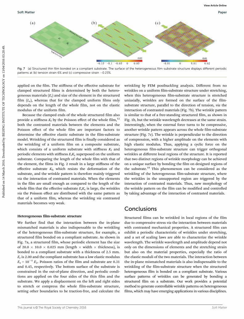
We further find that the interaction between the in-planemismatched materials is also indispensable to the wrinklingof the heterogeneous film-substrate structure, for example, astructured film bonded on a compliant substrate. As shown inFig. 7a, a structured film, whose periodic element has the sizeof 20.0 � 10.0 � 0.025 mm (length � width � thickness), isbonded to a compliant substrate with a thickness of 2.5 mm.Er is 2.00 and the compliant substrate has a low elastic modulusEs = 10�4 E2. Poisson ratios of the film and substrate are 0.31and 0.45, respectively. The bottom surface of the substrate isconstrained in the out-of-plane direction, and periodic condi-tions are applied on the four sides of the thin film and thesubstrate. We apply a displacement on the left and right sidesto stretch or compress the whole film-substrate structure,setting other boundaries to be traction-free, and calculate the
wrinkling by FEM postbuckling analysis. Different from nowrinkles on a uniform film-substrate structure under stretching,when this heterogeneous film-substrate structure is stretcheduniaxially, wrinkles are formed on the surface of the film-substrate structure, parallel to the direction of tension, via theinteraction of contrasted materials (Fig. 7b). The wrinkle patternis similar to that of a free-standing structured film, as shown inFig. 1b, but the wrinkle wavelength decreases at the same strain.Interestingly, when the external force turns to be compressive,another wrinkle pattern appears across the whole film-substratestructure (Fig. 7c). The wrinkle is perpendicular to the directionof compression, with a higher amplitude on the elements withhigh elastic modulus. Thus, applying a cyclic force on theheterogeneous film-substrate structure can trigger orthogonalwrinkles at different local regions of the structure. It is reportedthat two distinct regions of wrinkle morphology can be achievedon a unique surface by bonding the film on designed regions ofthe substrate.18 This phenomenon can be considered as thewrinkling of the heterogeneous film-substrate structure, wherethe wrinkles in the unsupported region are triggered by theinteraction of contrasted materials. Thus, new morphology ofthe wrinkle pattern on the film can be modified and controlledby taking advantage of the interaction of contrasted materials.
Conclusions
Structured films can be wrinkled in local regions of the filmdue to compressive stress via the interaction between materialswith contrasted mechanical properties. A structured film canexhibit a periodic characteristic of wrinkles under stretching,and a set of scaling laws are able to characterize the wrinklewavelength. The wrinkle wavelength and amplitude depend notonly on the dimensions of elements and the stretching strainbut also on the material properties, especially the ratio ofthe elastic moduli of the two materials. The interaction betweenthe in-plane mismatched materials is also indispensable to thewrinkling of the film-substrate structure when the structuredheterogeneous film is bonded on a compliant substrate. Varioussurface patterns of wrinkles can be generated by bonding astructured film on a substrate. Our work provides a potentialmethod to generate controllable wrinkle patterns on heterogeneousfilms, which may have emerging applications in various disciplines.
Fig. 7 (a) Structured thin film bonded on a compliant substrate. The surface of the heterogeneous film-substrate structure displays different periodicpatterns at (b) tension strain 6% and (c) compressive strain �0.23%.
Soft Matter Paper
Publ
ishe
d on
14
Mar
ch 2
016.
Dow
nloa
ded
by B
EIJ
ING
IN
STIT
UT
E O
F T
EC
HN
OL
OG
Y o
n 13
/04/
2016
03:
20:4
9.
View Article Online
Soft Matter This journal is©The Royal Society of Chemistry 2016
Acknowledgements
Support from NSFC (Grant No. 11202025, 11290153 and 11472044)is acknowledged.
Notes and references
1 J. A. Rogers, T. Someya and Y. G. Huang, Science, 2010, 327,1603–1607.
2 D. H. Kim and J. A. Rogers, Adv. Mater., 2008, 20, 4887–4892.3 A. B. Croll and A. J. Crosby, Macromolecules, 2012, 45,
4001–4006.4 J. M. Harris, J. Y. Huh, M. R. Semler, T. Ihle, C. M. Stafford,
S. D. Hudson, J. A. Fagan and E. K. Hobbie, Soft Matter,2013, 9, 11568–11575.
5 M. R. Semler, J. M. Harris, A. B. Croll and E. K. Hobbie, Phys.Rev. E: Stat., Nonlinear, Soft Matter Phys., 2013, 88, 032409.
6 E. K. Hobbie, D. O. Simien, J. A. Fagan, J. Y. Huh, J. Y.Chung, S. D. Hudson, J. Obrzut, J. F. Douglas and C. M.Stafford, Phys. Rev. Lett., 2010, 104, 125505.
7 C. M. Stafford, C. Harrison, K. L. Beers, A. Karim, E. J. Amis,M. R. Vanlandingham, H. C. Kim, W. Volksen, R. D. Millerand E. E. Simonyi, Nat. Mater., 2004, 3, 545–550.
8 J. Huang, M. Juszkiewicz, W. H. de Jeu, E. Cerda, T. Emrick,N. Menon and T. P. Russell, Science, 2007, 317, 650–653.
9 B. Li, Y. P. Cao, X. Q. Feng and H. Gao, Soft Matter, 2012, 8,5728–5745.
10 J. Dervaux, Y. Couder, M. A. Guedeau-Boudeville and M. BenAmar, Phys. Rev. Lett., 2011, 107, 018103.
11 W. T. S. Huck, Nat. Mater., 2005, 4, 271–272.12 E. Cerda and L. Mahadevan, Phys. Rev. Lett., 2003, 90, 074302.13 E. Cerda, J. Biomech., 2005, 38, 1598–1603.14 J. R. Blandino, J. D. Johnston and U. K. Dharamsi, J. Spacecr.
Rockets, 2002, 39, 717–724.15 Y. W. Wong and S. Pellegrino, J. Mech. Mater. Struct., 2006,
1, 3–25.
16 D. Yan, K. Zhang, F. Peng and G. Hu, Appl. Phys. Lett., 2014,105, 071905.
17 C. F. Guo, V. Nayyar, Z. Zhang, Y. Chen, J. Miao andR. Huang, and Q. Liu, Adv. Mater., 2012, 24, 3010–3014.
18 Y. Ebata and A. J. Crosby, Soft Matter, 2014, 10, 1963–1968.19 Y. Ebata, A. B. Croll and A. J. Crosby, Soft Matter, 2012, 8,
9086–9091.20 B. Li, F. Jia, Y. P. Cao, X. Q. Feng and H. Gao, Phys. Rev. Lett.,
2011, 106, 234301.21 P. Muller and J. Kierfeld, Phys. Rev. Lett., 2014, 112, 094303.22 J. Hure, B. Roman and J. Bico, Phys. Rev. Lett., 2012,
109, 054302.23 E. Cerda, K. Ravi-Chandar and L. Mahadevan, Nature, 2002,
419, 579–580.24 Z. Y. Huang, W. Hong and Z. Suo, J. Mech. Phys. Solids, 2005,
53, 2101–2118.25 V. Nayyar, K. Ravi-Chandar and R. Huang, Int. J. Solids
Struct., 2014, 51, 1847–1858.26 S. Cai, D. Breid, A. J. Crosby, Z. Suo and J. W. Hutchinson,
J. Mech. Phys. Solids, 2011, 59, 1094–1114.27 K. Zhang, H. Duan, B. L. Karihaloo and J. Wang, Proc. Natl.
Acad. Sci. U. S. A., 2010, 107, 9502–9506.28 Y. Su, B. Ji, K. C. Hwang and Y. Huang, J. Mech. Phys. Solids,
2012, 60, 1771–1790.29 R. Blossey, Nat. Mater., 2003, 2, 301–306.30 H. Liang and L. Mahadevan, Proc. Natl. Acad. Sci. U. S. A.,
2009, 106, 22049–22054.31 J. H. Lee, H. W. Ro, R. Huang, P. Lemaillet, T. A. Germer,
C. L. Soles and C. M. Stafford, Nano Lett., 2012, 12, 5995–5999.32 W. T. S. Huck, N. Bowden, P. Onck, T. Pardoen, J. W.
Hutchinson and G. M. Whitesides, Langmuir, 2000, 16,3497–3501.
33 N. Bowden, S. Brittain, A. G. Evans, J. W. Hutchinson andG. M. Whitesides, Nature, 1998, 393, 146–149.
34 A. Takei, F. Brau, B. Roman and J. Bico, Europhys. Lett.,2011, 96, 64001.
Paper Soft Matter
Publ
ishe
d on
14
Mar
ch 2
016.
Dow
nloa
ded
by B
EIJ
ING
IN
STIT
UT
E O
F T
EC
HN
OL
OG
Y o
n 13
/04/
2016
03:
20:4
9.
View Article Online


![Pulsed Laser Deposition of YSZ and Al2O3 Thin Films: Part 1 ......thin films [16-26]. Pulsed laser deposition has also been used for the development of nano-structured thin films [27,](https://img.pdfslide.us/doc/110x75/60f688b3c8026a3be761a2f6/pulsed-laser-deposition-of-ysz-and-al2o3-thin-films-part-1-thin-films-16-26.jpg)