Embed Size (px)
Citation preview
i
Government of Maharashtra Water Resources Department
PIPE DISTRIBUTION NETWORK FOR IRRIGATION
VOLUME I
2019
WRD HANDBOOK CHAPTER NO.4
ii
PREFACE
To achieve more crop per drop, it is not advisable to use conventional flow irrigation system for irrigation viz canals & distributaries. There is large scale water loss in this system. In the wake of above, Govt. of Maharashtra has adopted the policy to distribute irrigation water through Piped Distribution Network, vide Govt. Resolution of 09.06.2016 and Revised 13.01.2017. The Central Govt. has decided in 2017 to increase the water efficiency by 20% and directed the State Govt. accordingly. As there is significant use of water for irrigation, it is sensible to increase water use efficiency in the agriculture sector. This can be solely possible by adopting PDN as it overcomes the lacunas of the flow irrigation system viz land acquisition, lavish use of water from the farmers in the upper reaches of the canal and in high cost in hilly areas.
The design and construction of PDN network in no. of projects is stated in Maharashtra. To have uniformity and for optimisation of design for cost reduction field engineers and planners felt need of detailed guidelines for PDN plannig, Design, estimation and execution. So, Govt. of Maharashtra constiueted a committee for drafting of PDN Handbook (As per Govt. Resolution dated12.02.2019). Handbook Committee gone through detailed literature, deliberation and practical experience on site and prepared Two Volumes of PDN Handbook. Volume one covers PDN plannning to estimation and second volume is dedicated to detailed specifications of pipe and appurtenant works.
I Specialy thanks our Principal secretary Shri. Chahal Sir for giving us opportunity for writing of handbook on this important topic. I also give special thanks to Shri. R. R. Pawar, Secretary(CADA), Shri. S. K. Ghanekar, Secretary(Co-ordination) and Shri. Sanjay Belasare, Joint Secretary of Govt. of Maharashtra. I also notably mention the name of Shri R. E. Upasani, Chief Engineer(Retd.) who was member secretary and he has carried out the work with special interest. PDN Handbook Volume-I was mainly contributed and drafted by Shri. S. N. Kulkarni, Executive Engineer, Canal Design Div. No.4, CDO, Nasik. As well as Second volume Detailed Specification of pipe is drafted by Shri. R.R Shaha, Chief Engineer(Hydro), Pune and Shri. I. M. Chisti, Superintending Engineer, Quality Control Circle, Aurangabad. The efforts and contribution of these three people are noteworthy and committee is glad to appreciate & thanks these three persons. Shri. H. V. Gunale, Superintending Engineer, Sangli Irrigation Project Circle, sangli has contributed by writing on Estimate preparation guidelines. Committee also appreciates and thanks him. I also thank all the members of the committee for their studied
This is the second chapter of WRD after publication of chapter on Ferrocement. I am happy to publish the second chapter of WRD Manual on PDN.
Hope, it shall be useful for the engineers for the successful implementaion of PDN policy and achieving its objectives. It will be useful for project planners, design engineers, field engineers and maintenance staff as well.
(N. V. Shinde) Director General
Design, Training, Hydrology,Research & Safety MERI, Nashik.
iii
LIST OF PWD HANDBOOK CHAPTERS
1. Materials. 2. Masonry. 3. Reinforced Concrete Construction. 4. Prestressed Concrete. 5. Plastering and Pointing 6. Preparation of Project and Engineering Geology. 7. Surveying. 8. Excavation. 9. Foundation. 10. Building. 11. Town Planning. 12. Roads. 13. C.D. Works and Bridges. 14. Ports and Harbours. 15. Runways and Air-strips. 16. Electrical Works Connected with Buildings. 17. Soil Mechanics. 18. Hydraulics. 19. Hydrology and Water Planning. 20. Masonry. 21. Earth and Composite Dams. 22. Instrumentation. 23. Spillways. 24. Canals. 25. Irrigation and Irrigation Management. 26. Soil Survey of Irrigation Command, Land Drainage and Reclamation. 27. Hydro-power Scheme. 28. Construction of Tunnels. 29. Urban Water Supply. 30. Rural Water Supply. 31. Sanitary Engineering. 32. Construction Machinery. 33. Quality Control :
Part I : Cement Concrete, Part II : Earth Work. 34. Labour Laws. 35. Rate Analysis. 36. Construction Planning. 37. Part I – Land Acquision Part II – Valuation. 38. Mathematical Data and Miscellaneous Information. 39. Colgrout Masonary works. 40. Placement of concrete. 41. Ready Mix Concrete.
LIST OF WRD HANDBOOK CHAPTERS WRD 1. Ferrocement Technology. WRD 2. Pipe Distribution Network for Irrigation.

iv
ABBREVIATIONS
PDN :- Pipe Distribution Network.
GOI :- Government of India.
GOM :- Government of Maharashtra.
CDO :- Central Designs Organization.
MOWR :- Ministry of Water Resources.
CPHEEO :- Central Public Health and Environmental Engineering Organization
CWC :- Central Water Commission.
GIS :- Geographical Information System.
C.C.A. :- Culturable Command Area.
I.C.A. :- Irrigable Command Area.
H.G.L. :- Hydraulic Gradient Line.
U.T.M. :- Universal Transverse Mercator.
B.C. Soil :- Black Cotton Soil.
G.R. :- Government Resolution.
CR :-Coefficient of pipe roughness
lps :- Liter per Second.
SCADA :- Supervisory Control And Data Acquisition.
WUA :- Water User Association.
G.C.A. :- Gross Command Area.
v
CONTENTS
Sr. No.
Item Description Page No.
1 Introduction 1
2 Survey for pipe distribution system 3
3 Planning of pipe distribution network 5
3.1 General 5
3.2 Pipe Distribution Network (PDN) Planning. 6
3.3 Data Required For Piped Irrigation Network Planning. 7
3.4 Route Selection Of Pipe Network. 8
3.5 Guiding Principle For Deciding Carrying Capacity Of Pipe/Canal.
8
3.5.1 Carrying Capacity Of Pipe On The Basis Of Crop Water Requirement.
8
3.6 Design Of A Network For Irrigation By Rotation. 9
3.7 Preliminary Carrying Capacity Of Distributory/Minor 9
3.8 Procedure For Deciding The Carrying Capacity Of Main/Branch Line
9
3.9 Water Losses & Irrigation Efficiencies 10
3.10 Parameters To Be Borne In Mind For Economical Pipe Network.
10
3.11 How To Carry Out Planning. 10
3.12 Outlet 12
4 Types of Pipe Distribution Network 14
4.1 Direct pumping / Entire pressurized system 14
4.2 Partial Gravity & Partial pressurized system 15
4.3 Partial pressurized up to storage point & then gravity system 16
4.4 Pumping through booster pump from canal 17
5 Selection of pipe material 18
5.1 Pipe Materials 18
5.2 Selection of Pipe Materials 18
6 Hydraulics of pipe flow 34
6.1 Free Surface Flow. 34
6.2 Pipe Flow for Pressurized Flow. 34
6.3 Steady Flow 34
6.3.1 Law Of Conservation Of Mass. 34
6.4 Basic Hydraulic To Be Used In Design Of PDN 35
6.5 Various losses in Pipe Distribution Network 36
6.5.1 Friction Loss 36
6.5.2 Minor Losses 37
7 Pipe irrigation network design 38
8 Use of software for PDN design 46
8.1 EPANET 46
8.1.1 Features 46
8.1.2 Input data format 47
vi
8.1.3 Observations 47
8.2 Water-GEMS 47
8.2.1 Features 47
8.2.2 Input data format 48
8.2.3 Model Management 49
8.2.4 Interoperability interface and graphical editing 49
8.2.5 Observations 50
8.3 M S Excel Sheet 50
9 Valves AND BLOCKS 52
9.1 Valves 52
9.1.1 Gate Valve 52
9.1.2 Throttling Valve 52
9.1.3 Reflux Or Check Valve 53
9.1.4 Pressure Reducing Valve 53
9.1.5 Air Valve 54
9.1.6 Air vent 55
9.1.7 Drain or Scour Valve 55
9.1.8 Control Valve 55
9.1.9 Isolation valve 56
9.2 Thrust Blocks and Anchor Blocks 56
9.2.1 Thrust Blocks for Direct Pumping 57
9.2.2 Nalla and Road Crossings 57
10 Specifications for Various Types of Pipes. 58
10.1 High Density Polyethylene Pipe(HDPE) 59
10.2 Spirally Wound Steel Reinforced Pipes (SWSRP) 61
10.3 Polyvinyl Chloride Pipe (PVC) 64
10.4 Oriented Unplasticised Polyvinyl Chloride Pipe (PVC-O): 67
10.5 Glass Fiber Reinforced Plastic Pipe (GRP) 70
10.6 Prestressed Concrete Non-Cylinder Pipe (PSC) 72
10.7 Prestressed Concrete Cylinder Pipe (PCCP) 74
10.8 Bar/Wire Wrapped Steel Cylinder Pipe (BWSC) 77
10.9 Mild Steel Pipes (M.S.) 79
10.10 Ductile Iron Pipes (DI) 81
10.11 Common Provisions Related To All Pipe Types Are As Enumerated Below
84
10.11.1 Marking On Pipes 84
10.11.2 Post Delivery Testing of Pipes 84
10.11.3 Permanent Markings Of Pipe Alignment 84
10.11.4 Third Party Inspection 84
10.11.5 Quality Control & Quality Assuranc 85
10.11.6 Operation, Maintenance & Handling Over of the syastem 85
10.11.7 Backfilling of Pipe Trenches 85
11 Repairs & maintenance 86
11.1 Introduction 86
11.2 Strategy 86
11.3 Transmission System 88
vii
11.4 Distribution System 93
11.5 Pumping Machinery 97
11.6. Water Meters Instrumentation Telemetry & Scada 105
11.7 Repairs of Pipe Distribution System 111
12 Estimate Preparation Guidelines 115
12.1 Preamble 115
12.2 Estimate of detailed survey, alignment, design & approval of pipe distribution network
115
12.2.1 Estimate of command area 115
12.2.2 Item of alignment survey 115
12.2.3 Item of detailed design of PDN 115
12.2.4 Item to be covered in detailed estimate of PDN 116
13 References 119
14 Annexure 1-61
1
CHAPTER-I
INTRODUCTION
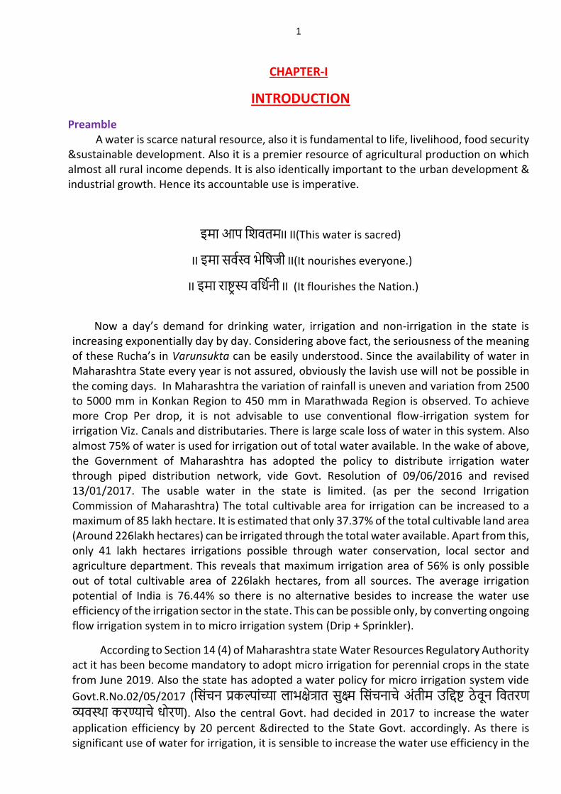
Preamble A water is scarce natural resource, also it is fundamental to life, livelihood, food security &sustainable development. Also it is a premier resource of agricultural production on which almost all rural income depends. It is also identically important to the urban development & industrial growth. Hence its accountable use is imperative.
II IIशिवतम आप इमा (This water is sacred)
II भशिजी सववसव इमा II (It nourishes everyone.)
II वशधवनी राषटरसय इमा II (It flourishes the Nation.)
Now a day’s demand for drinking water, irrigation and non-irrigation in the state is increasing exponentially day by day. Considering above fact, the seriousness of the meaning of these Rucha’s in Varunsukta can be easily understood. Since the availability of water in Maharashtra State every year is not assured, obviously the lavish use will not be possible in the coming days. In Maharashtra the variation of rainfall is uneven and variation from 2500 to 5000 mm in Konkan Region to 450 mm in Marathwada Region is observed. To achieve more Crop Per drop, it is not advisable to use conventional flow-irrigation system for irrigation Viz. Canals and distributaries. There is large scale loss of water in this system. Also almost 75% of water is used for irrigation out of total water available. In the wake of above, the Government of Maharashtra has adopted the policy to distribute irrigation water through piped distribution network, vide Govt. Resolution of 09/06/2016 and revised 13/01/2017. The usable water in the state is limited. (as per the second Irrigation Commission of Maharashtra) The total cultivable area for irrigation can be increased to a maximum of 85 lakh hectare. It is estimated that only 37.37% of the total cultivable land area (Around 226lakh hectares) can be irrigated through the total water available. Apart from this, only 41 lakh hectares irrigations possible through water conservation, local sector and agriculture department. This reveals that maximum irrigation area of 56% is only possible out of total cultivable area of 226lakh hectares, from all sources. The average irrigation potential of India is 76.44% so there is no alternative besides to increase the water use efficiency of the irrigation sector in the state. This can be possible only, by converting ongoing flow irrigation system in to micro irrigation system (Drip + Sprinkler).
According to Section 14 (4) of Maharashtra state Water Resources Regulatory Authority act it has been become mandatory to adopt micro irrigation for perennial crops in the state from June 2019. Also the state has adopted a water policy for micro irrigation system vide
Govt.R.No.02/05/2017 (शसिचन परकलािचया लाभकषतरात सकषम शसिचनाच अितीम उशिषट ठवन शवतरण
वयवसथा करणयाच धोरण). Also the central Govt. had decided in 2017 to increase the water application efficiency by 20 percent &directed to the State Govt. accordingly. As there is significant use of water for irrigation, it is sensible to increase the water use efficiency in the

2
agricultural sector. This can be solely possible by adopting Piped Distribution Network (PDN) as it overcomes the lacunas of the flow irrigation system viz. land acquisition, lavish use of water from the farmers in the upper reaches of the canal, System becomes expensive in hilly areas etc.
3
CHAPTER-II
SURVEY FOR PIPE DISTRIBUTION SYSTEM
2.1 As per the Government Resolution dated 02/02/2017; a piped irrigation system should preferably be used for the command areas, having ground slope 1:500 or more. Piped irrigation depends upon hydraulic gradient (H.G.L.) of the source hence piped irrigation system depends upon the topography of the area and H.G.L. of the source.
VIZ- 1) Land Acquisition is not amicable or expensive.
2) In hilly areas, where construction of traditional canal become more expensive.
3) In regions like Vidarbha, where horticulture crops are popular.
4) Commands having sandy soil, where percolation losses are predominant.
2.2 A detailed survey should be carried out by the state of art instruments like Total station, DGPS or Drone camera. This data becomes compatible to the Geographical information system (GIS) and also to many software used for the design of Pipe distribution system (Like Water Gems).
2.3 Based on a detailed survey carried out, the contour map should be prepared for 0.2 m contour intervals. A single command map of 0.2 m contour interval in a scale of 1:10000 should be prepared. Also for detailed planning of the PDN, the aforesaid command map in a scale of 1:6000 or 1:4000 are also required for chak planning. Or in case of large project at least command area should be readable. The map should be inclusive of all the details like Buildings, Gavthan, Forest, Roads, Railways, Nallas, & Rivers etc. and it should be in a Auto-cad drawing format.
2.3.1. In the wake of above, a detailed circular vide letter no. जा.कर.मसिसि/अ.अ.(का)/
पररपतरक/726/2018 शिनािक 05/10/2018 issued by the C.D.O. should be followed regarding this.
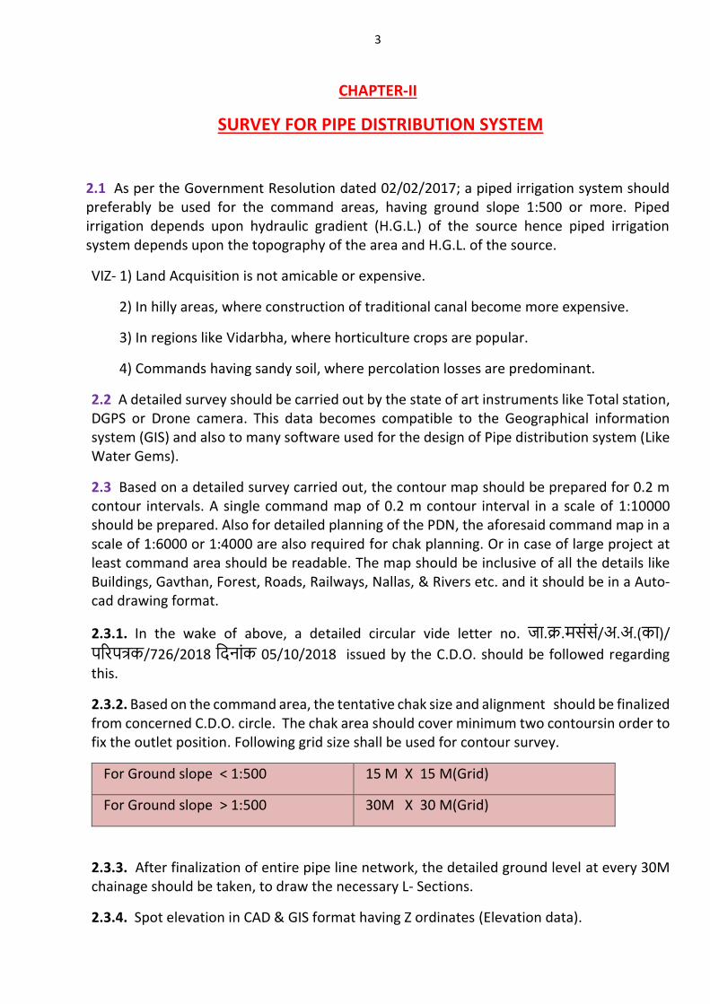
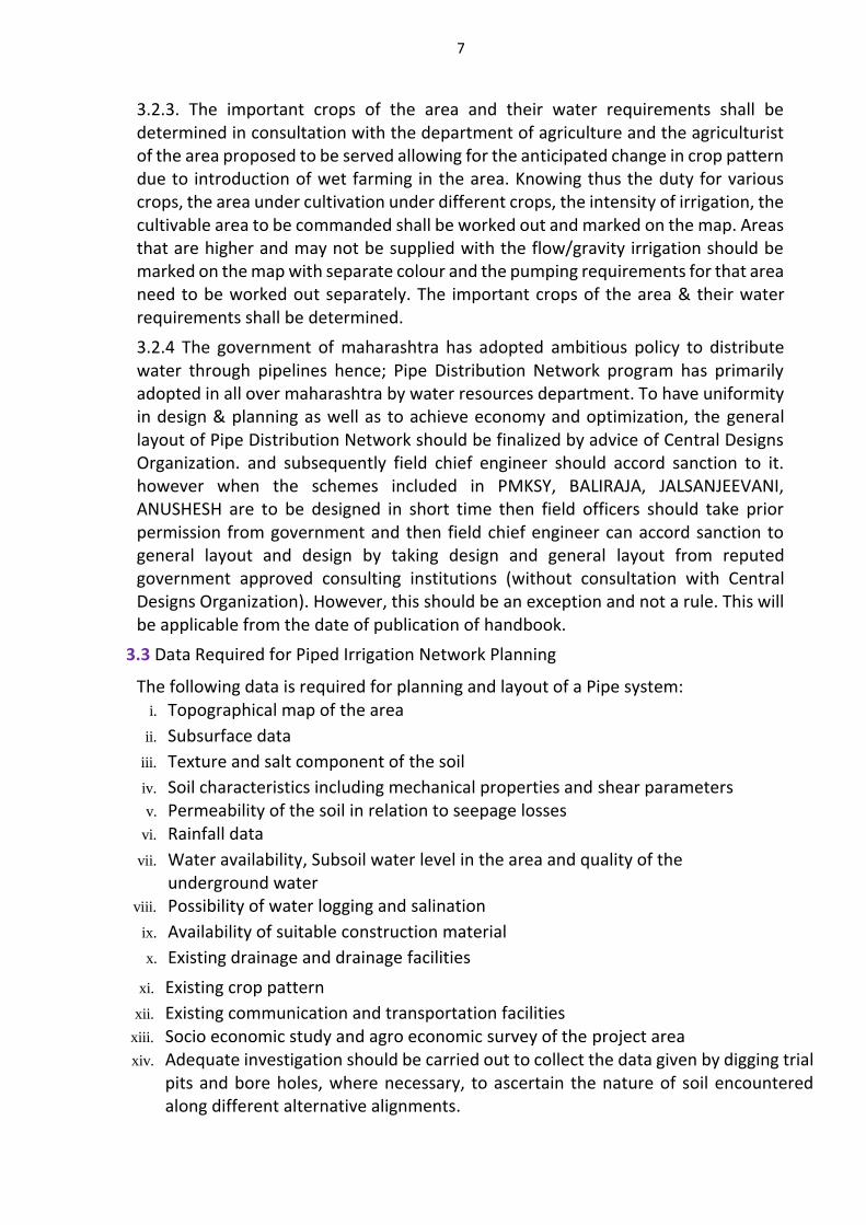
2.3.2. Based on the command area, the tentative chak size and alignment should be finalized from concerned C.D.O. circle. The chak area should cover minimum two contoursin order to fix the outlet position. Following grid size shall be used for contour survey.
For Ground slope < 1:500 15 M X 15 M(Grid)
For Ground slope > 1:500 30M X 30 M(Grid)
2.3.3. After finalization of entire pipe line network, the detailed ground level at every 30M chainage should be taken, to draw the necessary L- Sections.
2.3.4. Spot elevation in CAD & GIS format having Z ordinates (Elevation data).

4
2.3.5. The contour interval should be such that at least two contours are falling within each chak. Depending upon ground slope contour interval may vary.
2.3.6. DEM (Digital Elevation Model) (GIS shape file) or Bentley DTM (Digital Terrain Model) in DGN (Design) format.
5
CHAPTER-III
PLANNING OF PIPE DISTRIBUTION NETWORK
3.1 General
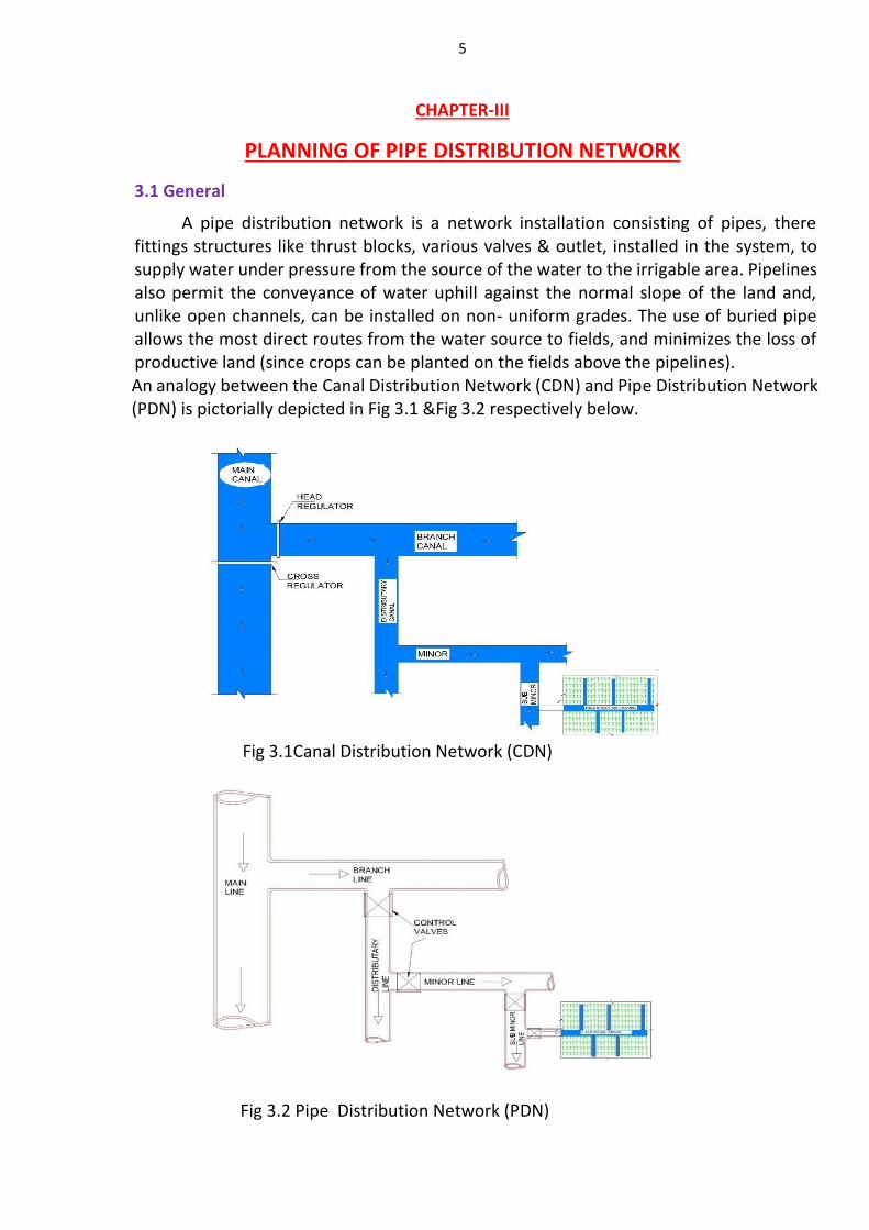
A pipe distribution network is a network installation consisting of pipes, there fittings structures like thrust blocks, various valves & outlet, installed in the system, to supply water under pressure from the source of the water to the irrigable area. Pipelines also permit the conveyance of water uphill against the normal slope of the land and, unlike open channels, can be installed on non- uniform grades. The use of buried pipe allows the most direct routes from the water source to fields, and minimizes the loss of productive land (since crops can be planted on the fields above the pipelines). An analogy between the Canal Distribution Network (CDN) and Pipe Distribution Network (PDN) is pictorially depicted in Fig 3.1 &Fig 3.2 respectively below.
Fig 3.1Canal Distribution Network (CDN)
Fig 3.2 Pipe Distribution Network (PDN)
6
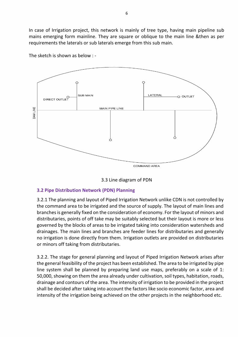
In case of Irrigation project, this network is mainly of tree type, having main pipeline sub mains emerging form mainline. They are square or oblique to the main line &then as per requirements the laterals or sub laterals emerge from this sub main. The sketch is shown as below : -
3.3 Line diagram of PDN
3.2 Pipe Distribution Network (PDN) Planning
3.2.1 The planning and layout of Piped Irrigation Network unlike CDN is not controlled by the command area to be irrigated and the source of supply. The layout of main lines and branches is generally fixed on the consideration of economy. For the layout of minors and distributaries, points of off take may be suitably selected but their layout is more or less governed by the blocks of areas to be irrigated taking into consideration watersheds and drainages. The main lines and branches are feeder lines for distributaries and generally no irrigation is done directly from them. Irrigation outlets are provided on distributaries or minors off taking from distributaries.
3.2.2. The stage for general planning and layout of Piped Irrigation Network arises after the general feasibility of the project has been established. The area to be irrigated by pipe line system shall be planned by preparing land use maps, preferably on a scale of 1: 50,000, showing on them the area already under cultivation, soil types, habitation, roads, drainage and contours of the area. The intensity of irrigation to be provided in the project shall be decided after taking into account the factors like socio economic factor, area and intensity of the irrigation being achieved on the other projects in the neighborhood etc.
7
3.2.3. The important crops of the area and their water requirements shall be determined in consultation with the department of agriculture and the agriculturist of the area proposed to be served allowing for the anticipated change in crop pattern due to introduction of wet farming in the area. Knowing thus the duty for various crops, the area under cultivation under different crops, the intensity of irrigation, the cultivable area to be commanded shall be worked out and marked on the map. Areas that are higher and may not be supplied with the flow/gravity irrigation should be marked on the map with separate colour and the pumping requirements for that area need to be worked out separately. The important crops of the area & their water requirements shall be determined.
3.2.4 The government of maharashtra has adopted ambitious policy to distribute water through pipelines hence; Pipe Distribution Network program has primarily adopted in all over maharashtra by water resources department. To have uniformity in design & planning as well as to achieve economy and optimization, the general layout of Pipe Distribution Network should be finalized by advice of Central Designs Organization. and subsequently field chief engineer should accord sanction to it. however when the schemes included in PMKSY, BALIRAJA, JALSANJEEVANI, ANUSHESH are to be designed in short time then field officers should take prior permission from government and then field chief engineer can accord sanction to general layout and design by taking design and general layout from reputed government approved consulting institutions (without consultation with Central Designs Organization). However, this should be an exception and not a rule. This will be applicable from the date of publication of handbook.
3.3 Data Required for Piped Irrigation Network Planning
The following data is required for planning and layout of a Pipe system: i. Topographical map of the area
ii. Subsurface data
iii. Texture and salt component of the soil
iv. Soil characteristics including mechanical properties and shear parameters v. Permeability of the soil in relation to seepage losses
vi. Rainfall data
vii. Water availability, Subsoil water level in the area and quality of the underground water
viii. Possibility of water logging and salination
ix. Availability of suitable construction material
x. Existing drainage and drainage facilities
xi. Existing crop pattern
xii. Existing communication and transportation facilities xiii. Socio economic study and agro economic survey of the project area xiv. Adequate investigation should be carried out to collect the data given by digging trial
pits and bore holes, where necessary, to ascertain the nature of soil encountered along different alternative alignments.
8
3.4 Route Selection of Pipe Network
1. As far as possible Length of pipelines in the network shall be kept minimum. 2. Pumping is avoided if possible or least pumping effort is needed.
3. High water pressure is avoided. Numbers of appurtenances (gate valve, check valve, drain, air release valve, pressure break valve) are minimized.
4 Very low or high velocities are avoided because low velocities cause Sedimentation in pipes and high velocities cause corrosion of pipe as well as more headloss. This results into most economical system.
5. If horizontal pipe sections are used, release of air and drain the dirt will not
be possible. So, in case of horizontal ground surface, artificial slopes are given to
pipes to be laid.
3.5 Guiding Principle for deciding Carrying Capacity of Pipe/Canal
The carrying capacity of the Piped Irrigation Network/CDN shall be maximum of; a) The carrying capacity calculated on the basis of the fortnightly crop water requirement
as per the design cropping pattern and planned Irrigated Cropped Area (ICA) of the project as per Administratively Approved project report but considering 12days flow period in a Fortnight.
OR
b) The carrying capacity calculated on basis of due water entitlement of the Culturable Command Area (CCA) of the Pipe line or distributary as per the provisions of Acts of State Level Authorities.
OR
c) The carrying capacity calculated on basis of the operation schedule of the pipe/canal or distributaries. The operation on the basis of 12 days on and 2 days off in a fortnight is preferable or as per the requirement.
The procedure to work out carrying capacity of canal for above alternatives is as given below:
3.5.1 Carrying capacity of pipe on the basis of crop water requirement: While deciding the carrying capacity of the pipe, the fortnightly crop water
requirement of the planned Cultural Command Area (CCA) of the Canal/Pipe shall be calculated by Modified Penman Method, for this cropping pattern approved by the concerned Authority shall be considered. Generally the C.C.A. of the pipe line shall be decided after completion of detailed command area survey of the project. PDN is such a water conductor system which have minimum losses is transit, so every effort should be made that maximum area should be brought under irrigation, hence there should not be any distinction between C.C.A. & I.C.A. so, as much as C.C.A. can be brought under irrigation and efforts should be made to restore the loss of irrigation area due to diversion of water to non irrigation use .
9
3.6 Design of a Network for Irrigation By Rotation
When pipe irrigation system is designed to run entire outlets in the command at the same time, due consideration must be given to strictly maintain the water level in the source. Abusive use of water is immediately detected at once by the rightful user whose supply vanishes in so far as the area of the chak /block is comparatively very small. Piped Irrigation Network, can be easily designed to keep the discharge of pipe outlet proportionate to it culturable area, and entire outlets to run at a time, hence there is no head, middle and tail reach differentiation of the command. It is essential to form user group before execution of the Piped Irrigation Network and hand over the network immediately to the user group for further supervision and protection.
3.7 Preliminary Carrying Capacity of Distributary & Minor
Detailed layout planning of Piped Distribution Network (PDN) should be done after completion of detailed command survey. The procedure for deciding carrying capacity of Distributaries / Minor is given below:
i. It shall be presumed that the fortnightly peak water requirement at the outlet head with Piped Irrigation Network is to fulfill with a flow period of 12 days, in a fortnight. The discharge at the chak head is kept proportionate to the chak areas. Thus the time period of entire outlets is constant and delivering (equitable distribution) same amount of total volume of water per ha.
ii. As per the guideline given in GR dtd 02/02/2017, chak size should be 5 -12 ha. If the required discharged at outlet as per cropping pattern is less than 10 lps, then outlet should be grouped or scheduled in such a way that group of outlet will have 10 lps discharge & each outlet will run at 10 lps for few days within group.
iii. For the rotation there should be proper grouping and scheduling of chak on sub-minor or lateral so that each outlet can discharge 8-10 lit/sec of water.
iv. Estimate maximum running days of PDN (Entire outlets) in the respective fortnight for water requirement by using appropriate efficiency from root zone to outlet head having proportionate discharge.
v. Determine carrying capacity of minor / distributaries in different reaches considering appropriate conveyance efficiency as given in Table 3.1.
3.8 Procedure for Deciding the Carrying Capacity of Main / Branch Line Prepare a statement of fortnightly net irrigation requirement (NIR) at root zone in mm.
i. Select the fortnight having maximum irrigation requirement i.e. peak water requirement and use this peak water requirement for designing the system.
ii. Convert the peak water requirement of root zone to the requirement at Main Canal/Pipe or Branch head using appropriate efficiencies.
iii. Workout the total volume of water required at canal head or Head Regulator for complete ICA of the system.
iv. Workout Canal/Pipe capacity for delivering the peak volume in a given flow period (if rotation is adopted for distributaries use 12days flow period for the peak rotation). If original canal or distributary is designed for 6 days rotation then design PDN system for 6 days accordingly.
10
3.9 Water Losses and Irrigation Efficiencies
To account for losses of water incurred during conveyance and application to the field, and efficiency factor should be included while calculating the project irrigation requirements. The project efficiency is normally divided into two stages each of which is affected by a different set of conditions.
a) Conveyance Loss- It is quatum of water loss in the system due to leakage etc. and it is assumed as 5% of Net irrigation requirement for PDN.
b) Field application Efficiency, Ea.: Ratio between water directly available to the crop and that received at the field inlet.
Table 3.1
Conveyance Efficiency Of pipe
Method of conveyance/ irrigation
Micro Irrigation Surface
Irrigation
Sprinkler Drip
Pipe based Conveyance
Water Loss in conveyance system
5 % 5 % 5 %
Field Application efficiency (%)
75 90 75
3.10 - Parameters to be borne in mind for economical pipe network: -
1) Length of the pipe lines in the network is to be minimum, as much as possible 2) Most preferably, pumping is to be avoided. 3)Sometimes, due to Geography of the command area, high pressures are unavoidable, but to be avoided. 4)The maximum velocity limit in each pipeline except PVC pipe is increased to 3 m/s(As per MOWR guidelines on PDN, July.2017). According to available residual head velocity in each pipe should be controlled. 5) Number of valves & thrust blocks, should be minimum. 6) Choice of proper pipe type can render a good economical network. 3.11 How to carry out Planning: - The Engineer in charge of the work are the men who are closely acquainted with the project or command area, so he should be involved in the pipeline alignment planning. Basically the contour map of the command area to be studied in detail, before fixing the alignment. Two types of command come across while planning.
11
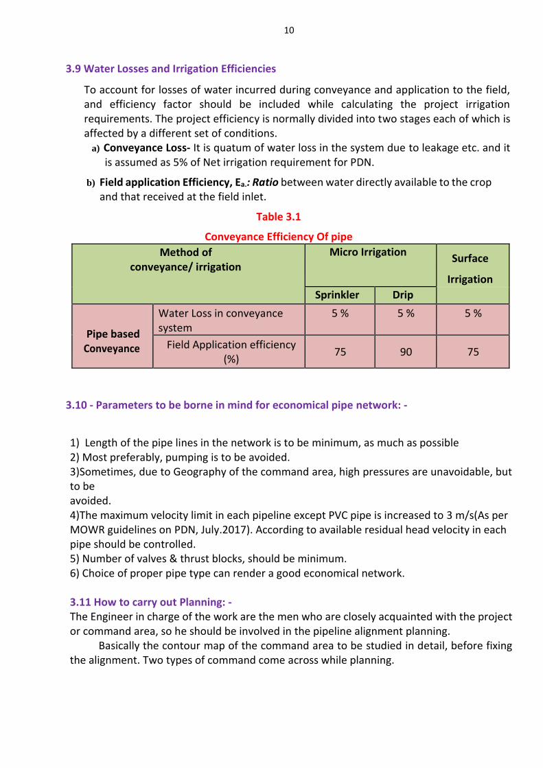
3.11 (a) If the contour lines are ridging @ the center& contour interval is decreasing to the downstream.
3.4 Alignment of PDN If contour lines are ridging @ center & decreasing to the downstream.
In this case ridge line can be mark as the main line for piped distribution network and sub main and laterals can be aligned towards downstream along the ridge line. As the main line is considered as the ridge line natural head can be utilized easily to irrigate farthest chak with economical pipe diameter
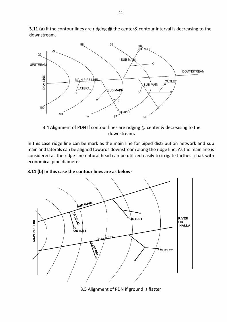
3.11 (b) In this case the contour lines are as below-
3.5 Alignment of PDN if ground is flatter
12
In this case ridge line cannot be marked easily. The ground is flatter, so the main line for piped distribution network is considered as the one of the contour line. Command area can be divided into different zones according to decreasing contours and each zone should be irrigated through sub main emerging from main line.
3.11 (c) Chak size: - The chak size should be between 5 ha to 12 ha, so that every farmer can easily irrigate his farm. The per hectare discharge of command area (m3/sec/ha) is a governing factor for deciding the Chak size. A minimum 10 lit/sec discharge is required at every outlet point to exercise the option of conventional flow irrigation behind pipe outlet. However actual discharge required as per modified penman method for a chak may be less than 10 lps discharge, in such cases keeping total quantum of water required to irrigate chak; we have to schedule two or three chak outlet operation in sequence. 3.12 Outlet: -
Outlet is the last appurtenance in pipe distribution network which actually supplies water to each chak. Outlet position is decided on the basis of the topography of chak. It is provided at the highest location in chak so that water can be supplied to each farm by gravity. As Every chak contain more than one farm so the local arrangement is made to facilitate the supply of water to each chak; On the basis of this arrangement oulets are devided into following three categories.
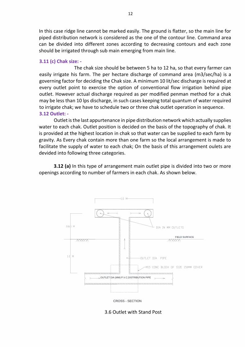
3.12 (a) In this type of arrangement main outlet pipe is divided into two or more
openings according to number of farmers in each chak. As shown below.
3.6 Outlet with Stand Post
OUTLET DIA (MM) P.V.C.DISTRIBUTION PIPE
CROSS - SECTION
FIELD SURFACE
13
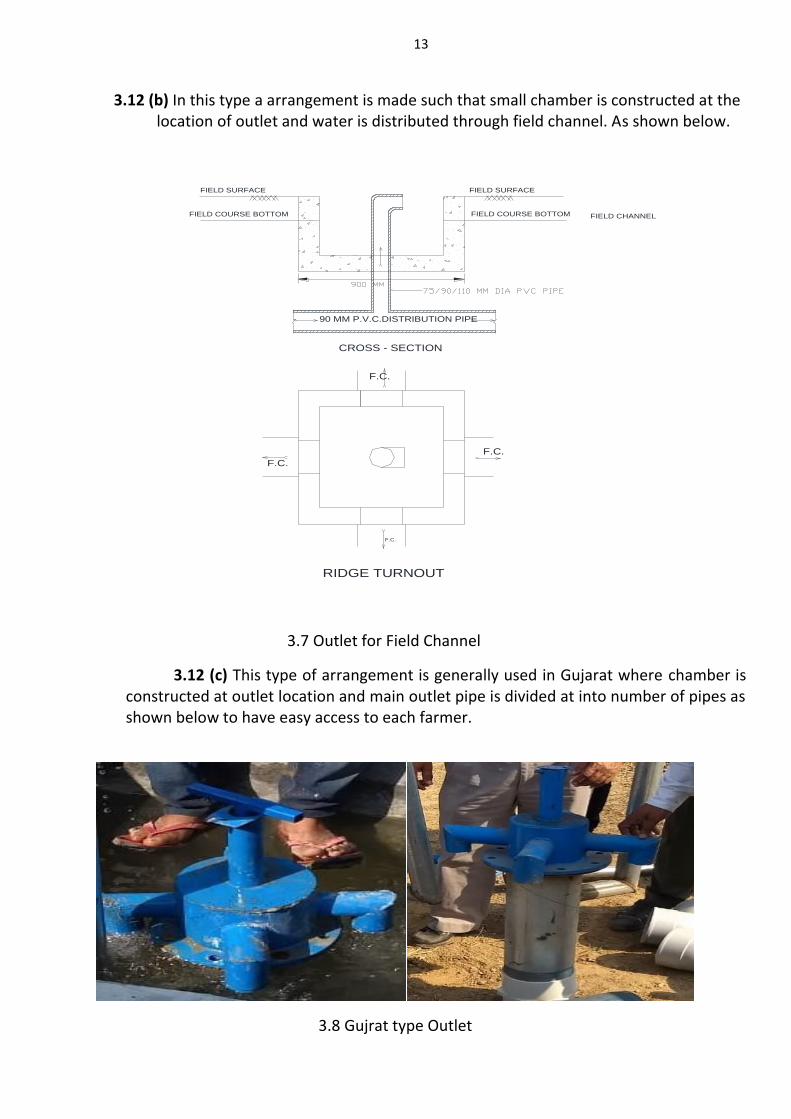
3.12 (b) In this type a arrangement is made such that small chamber is constructed at the location of outlet and water is distributed through field channel. As shown below.
3.7 Outlet for Field Channel
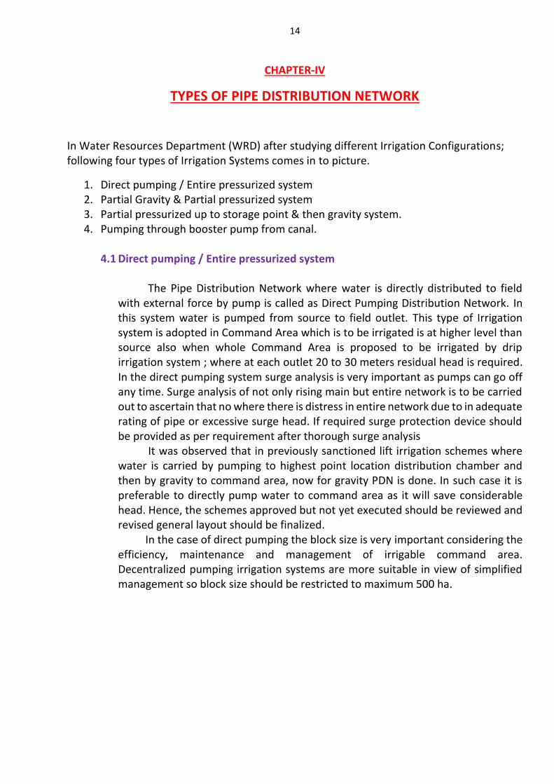
3.12 (c) This type of arrangement is generally used in Gujarat where chamber is constructed at outlet location and main outlet pipe is divided at into number of pipes as shown below to have easy access to each farmer.
3.8 Gujrat type Outlet
90 MM P.V.C.DISTRIBUTION PIPE
FIELD SURFACEFIELD SURFACE
FIELD COURSE BOTTOM
F.C.
F.C.
F.C.
F.C.
CROSS - SECTION
FIELD COURSE BOTTOM FIELD CHANNEL
RIDGE TURNOUT
14
CHAPTER-IV
TYPES OF PIPE DISTRIBUTION NETWORK
In Water Resources Department (WRD) after studying different Irrigation Configurations; following four types of Irrigation Systems comes in to picture.
1. Direct pumping / Entire pressurized system 2. Partial Gravity & Partial pressurized system 3. Partial pressurized up to storage point & then gravity system. 4. Pumping through booster pump from canal.
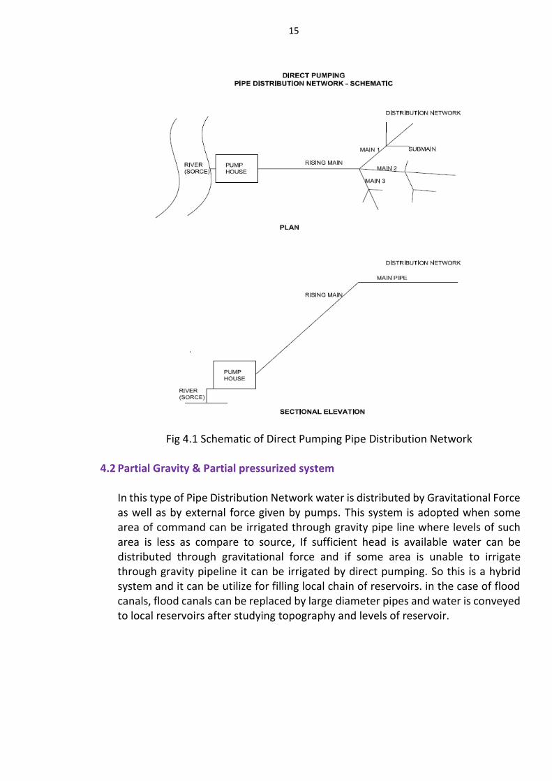
4.1 Direct pumping / Entire pressurized system
The Pipe Distribution Network where water is directly distributed to field with external force by pump is called as Direct Pumping Distribution Network. In this system water is pumped from source to field outlet. This type of Irrigation system is adopted in Command Area which is to be irrigated is at higher level than source also when whole Command Area is proposed to be irrigated by drip irrigation system ; where at each outlet 20 to 30 meters residual head is required. In the direct pumping system surge analysis is very important as pumps can go off any time. Surge analysis of not only rising main but entire network is to be carried out to ascertain that no where there is distress in entire network due to in adequate rating of pipe or excessive surge head. If required surge protection device should be provided as per requirement after thorough surge analysis It was observed that in previously sanctioned lift irrigation schemes where water is carried by pumping to highest point location distribution chamber and then by gravity to command area, now for gravity PDN is done. In such case it is preferable to directly pump water to command area as it will save considerable head. Hence, the schemes approved but not yet executed should be reviewed and revised general layout should be finalized. In the case of direct pumping the block size is very important considering the efficiency, maintenance and management of irrigable command area. Decentralized pumping irrigation systems are more suitable in view of simplified management so block size should be restricted to maximum 500 ha.
15
Fig 4.1 Schematic of Direct Pumping Pipe Distribution Network
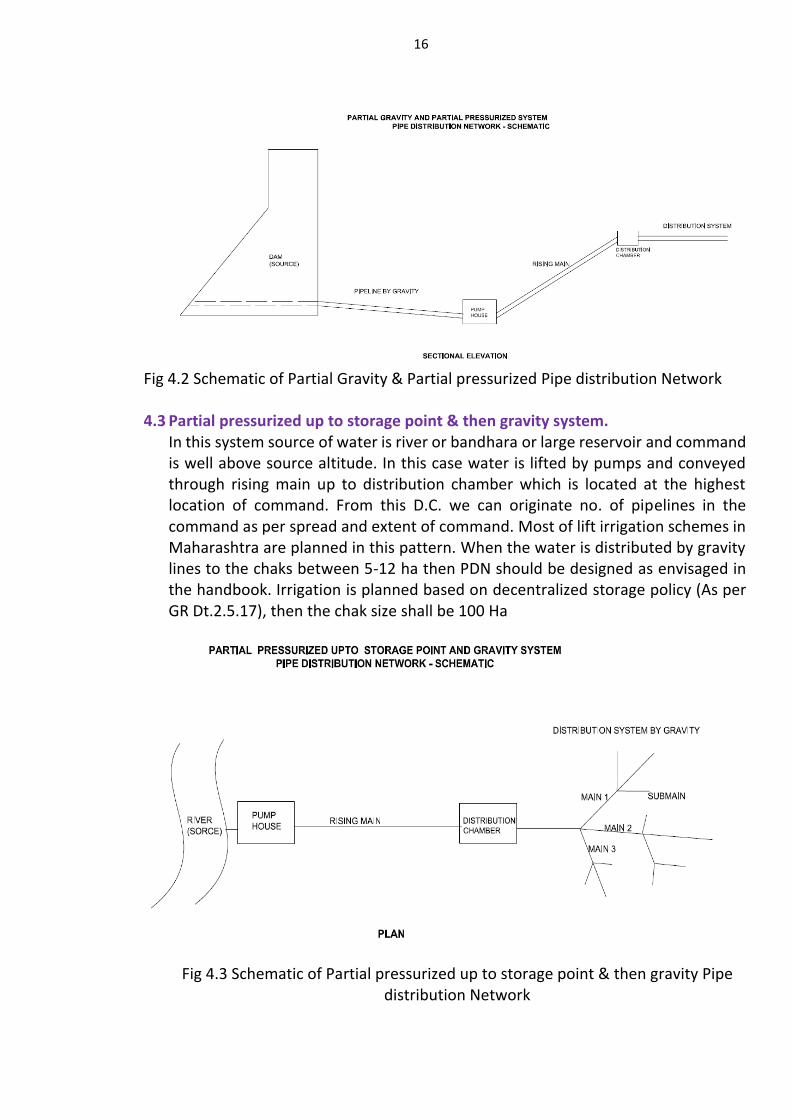
4.2 Partial Gravity & Partial pressurized system
In this type of Pipe Distribution Network water is distributed by Gravitational Force as well as by external force given by pumps. This system is adopted when some area of command can be irrigated through gravity pipe line where levels of such area is less as compare to source, If sufficient head is available water can be distributed through gravitational force and if some area is unable to irrigate through gravity pipeline it can be irrigated by direct pumping. So this is a hybrid system and it can be utilize for filling local chain of reservoirs. in the case of flood canals, flood canals can be replaced by large diameter pipes and water is conveyed to local reservoirs after studying topography and levels of reservoir.
16
Fig 4.2 Schematic of Partial Gravity & Partial pressurized Pipe distribution Network
4.3 Partial pressurized up to storage point & then gravity system.
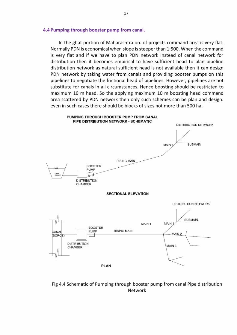
In this system source of water is river or bandhara or large reservoir and command is well above source altitude. In this case water is lifted by pumps and conveyed through rising main up to distribution chamber which is located at the highest location of command. From this D.C. we can originate no. of pipelines in the command as per spread and extent of command. Most of lift irrigation schemes in Maharashtra are planned in this pattern. When the water is distributed by gravity lines to the chaks between 5-12 ha then PDN should be designed as envisaged in the handbook. Irrigation is planned based on decentralized storage policy (As per GR Dt.2.5.17), then the chak size shall be 100 Ha
Fig 4.3 Schematic of Partial pressurized up to storage point & then gravity Pipe
distribution Network
17
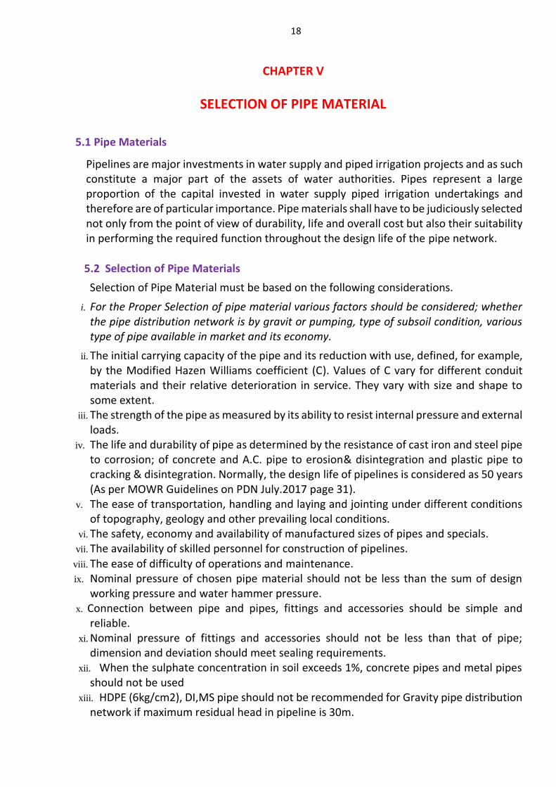
4.4 Pumping through booster pump from canal. In the ghat portion of Maharashtra on. of projects command area is very flat. Normally PDN is economical when slope is steeper than 1:500. When the command is very flat and if we have to plan PDN network instead of canal network for distribution then it becomes empirical to have sufficient head to plan pipeline distribution network as natural sufficient head is not available then it can design PDN network by taking water from canals and providing booster pumps on this pipelines to negotiate the frictional head of pipelines. However, pipelines are not substitute for canals in all circumstances. Hence boosting should be restricted to maximum 10 m head. So the applying maximum 10 m boosting head command area scattered by PDN network then only such schemes can be plan and design. even in such cases there should be blocks of sizes not more than 500 ha.
Fig 4.4 Schematic of Pumping through booster pump from canal Pipe distribution
Network
18
CHAPTER V
SELECTION OF PIPE MATERIAL
5.1 Pipe Materials
Pipelines are major investments in water supply and piped irrigation projects and as such constitute a major part of the assets of water authorities. Pipes represent a large proportion of the capital invested in water supply piped irrigation undertakings and therefore are of particular importance. Pipe materials shall have to be judiciously selected not only from the point of view of durability, life and overall cost but also their suitability in performing the required function throughout the design life of the pipe network.
5.2 Selection of Pipe Materials
Selection of Pipe Material must be based on the following considerations.
i. For the Proper Selection of pipe material various factors should be considered; whether the pipe distribution network is by gravit or pumping, type of subsoil condition, various type of pipe available in market and its economy.
ii. The initial carrying capacity of the pipe and its reduction with use, defined, for example, by the Modified Hazen Williams coefficient (C). Values of C vary for different conduit materials and their relative deterioration in service. They vary with size and shape to some extent.
iii. The strength of the pipe as measured by its ability to resist internal pressure and external loads.
iv. The life and durability of pipe as determined by the resistance of cast iron and steel pipe to corrosion; of concrete and A.C. pipe to erosion& disintegration and plastic pipe to cracking & disintegration. Normally, the design life of pipelines is considered as 50 years (As per MOWR Guidelines on PDN July.2017 page 31).
v. The ease of transportation, handling and laying and jointing under different conditions of topography, geology and other prevailing local conditions.
vi. The safety, economy and availability of manufactured sizes of pipes and specials. vii. The availability of skilled personnel for construction of pipelines.
viii. The ease of difficulty of operations and maintenance. ix. Nominal pressure of chosen pipe material should not be less than the sum of design
working pressure and water hammer pressure. x. Connection between pipe and pipes, fittings and accessories should be simple and
reliable. xi. Nominal pressure of fittings and accessories should not be less than that of pipe;
dimension and deviation should meet sealing requirements. xii. When the sulphate concentration in soil exceeds 1%, concrete pipes and metal pipes
should not be used xiii. HDPE (6kg/cm2), DI,MS pipe should not be recommended for Gravity pipe distribution
network if maximum residual head in pipeline is 30m.
19
xiv. In gravity pipe distribution network for main line if the diameter of pipe is above 800 mm then GRP or PSC pipe should be preferred.
xv. For lift irrigation with drip; use of HDPE pipe should be considered. xvi. Cast -in-situ pipe should not be used for the piped distribution network. xvii. After the laying of pipes proper quality control is mandatory. xviii. Pipe line in B.C. soils/expansive soil: - xix. A special care has to be taken while laying pipelines in black cotton soil and xx. Expansive soils. for that following things should be strictly observed. xxi. In black cotton soil or in expansive soil, PSC pipe should be avoided xxii. in B.C. soils/ expansive soil alignment of pipe can be disturbed due to excessive soil
pressure; in that case no. of anchor block should be increased and general criteria for providing anchor block should be at 100 m interval
xxiii. The pipe type having rigid joint can have crack in B.C. soils, in such case pipe having flexible joints should be preferred.
xxiv. while designing Pipe Distribution Network (PDN), correct data regarding swelling pressure of B.C. soils/expansive soil should be taken into account from field to avoid further displacement of alignment and also provide design of CNS material with appropriate thickness.
The life and durability of pipe depends on several factors including inherent strength of the pipe material, the manufacturing process along with quality control, handling, transportation, laying and jointing of pipeline, surronding soil condition, and quality of water. Normally design period of pipeline is considered as 50 years(As per MOWR Guidelines on PDN July.2017 page 31). where the pipes have been manufactured properly as per specifications, & pipeline is designed and installed with adequate quality control and strict supervision.
The cost of pipe material and its durability or design life are the two major governing factors of selection of pipe material. The pipeline may have very long life but may also be relatively expensive in terms of capital recurring costs and, therefore, it is very necessary to carry out a detailed economic analysis / (Life cycle analysis) before selecting pipe materials.
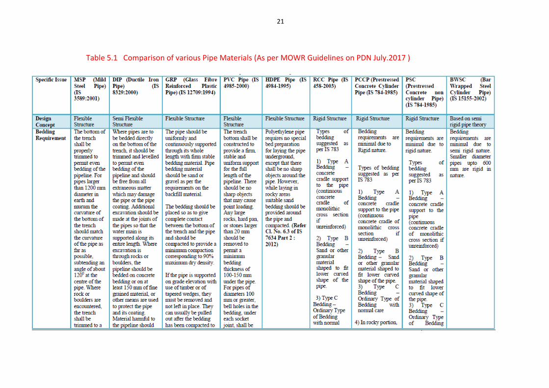
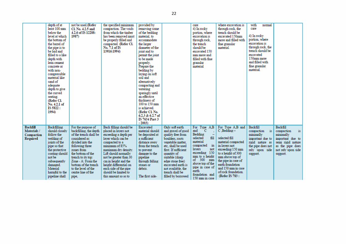
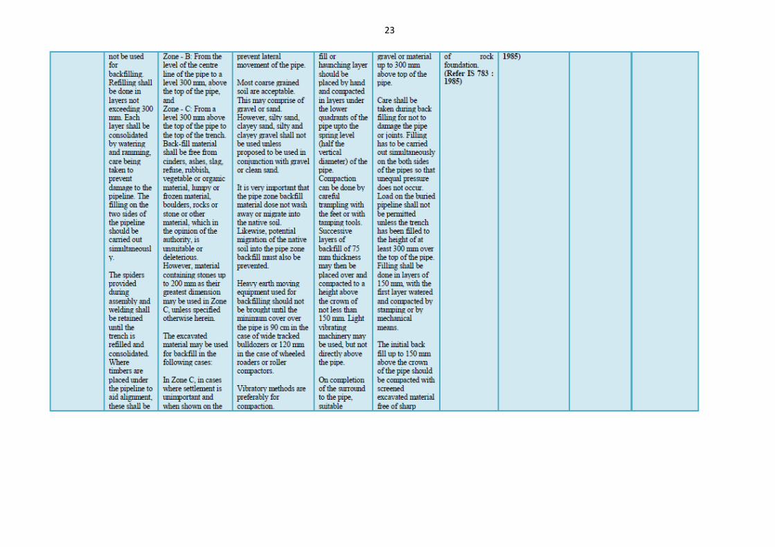
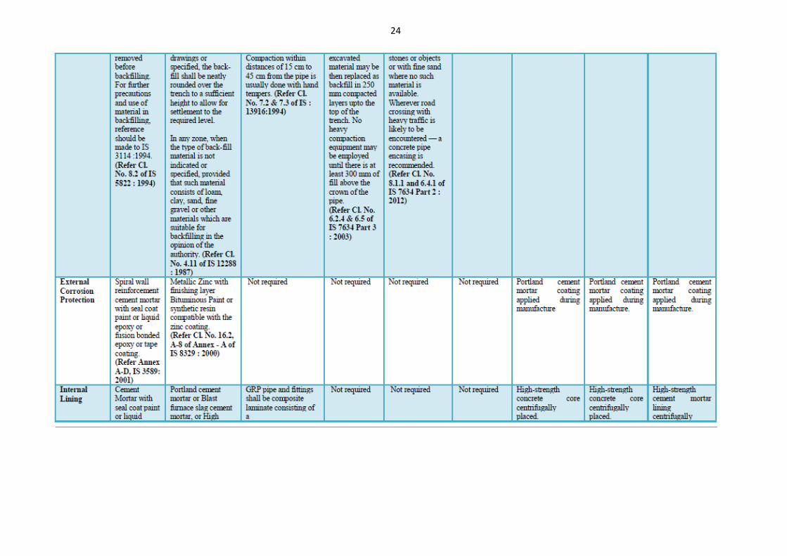
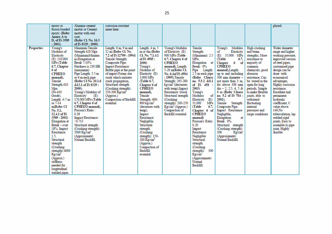
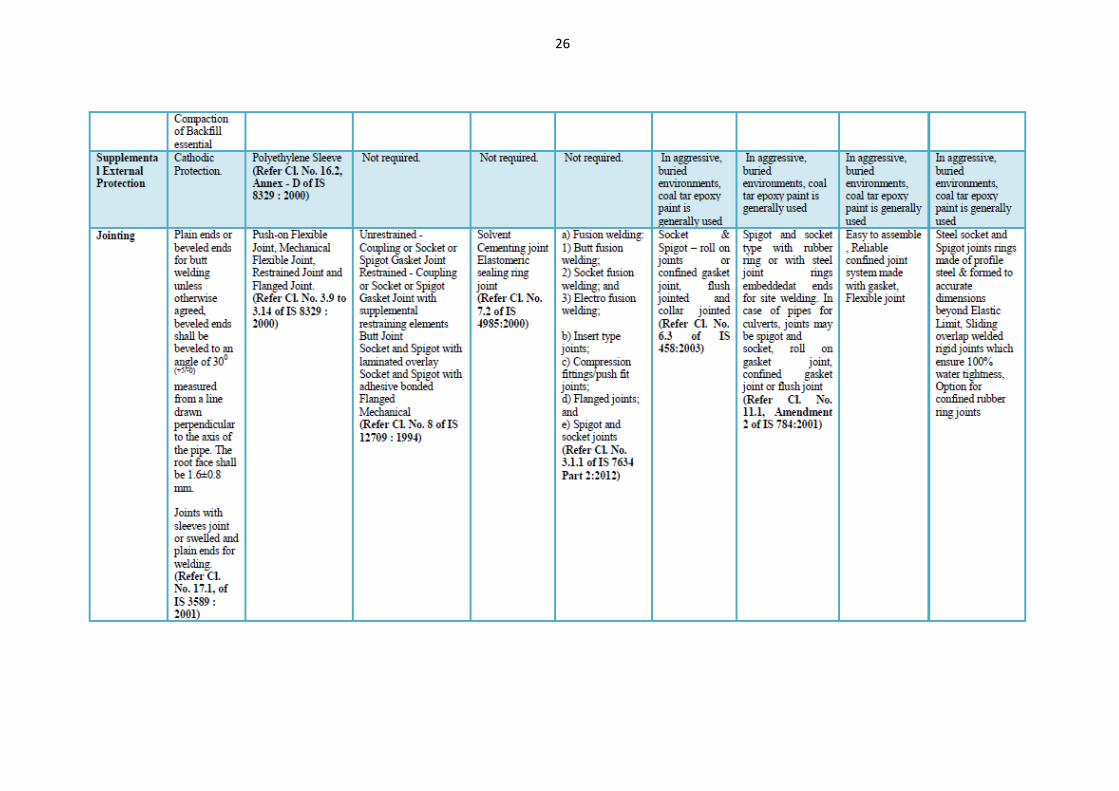
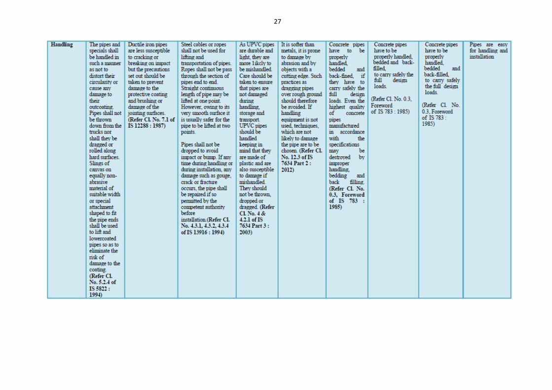
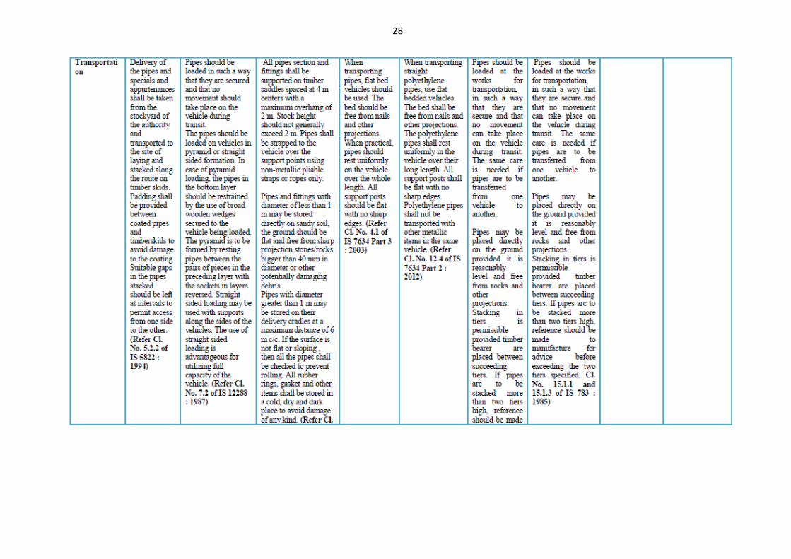
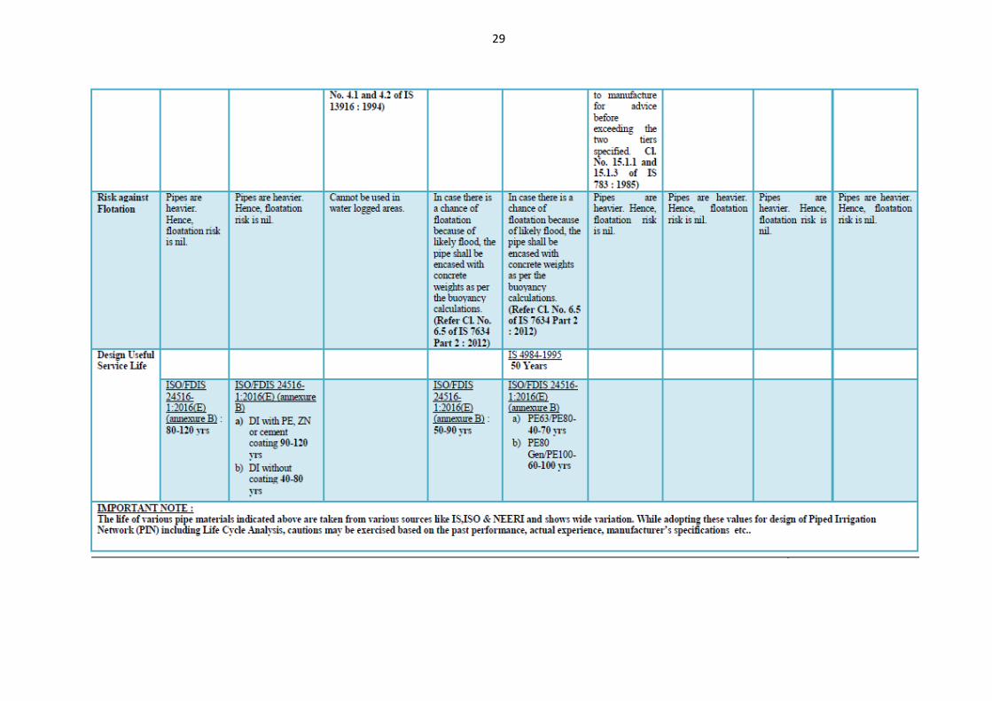
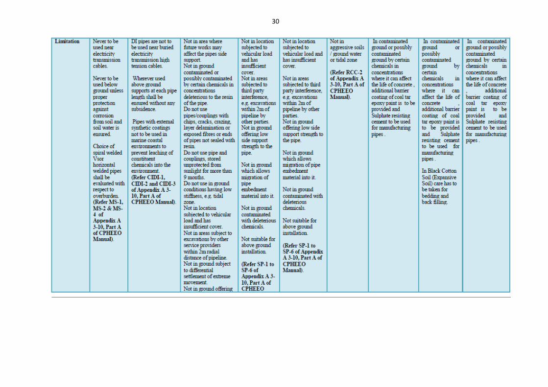
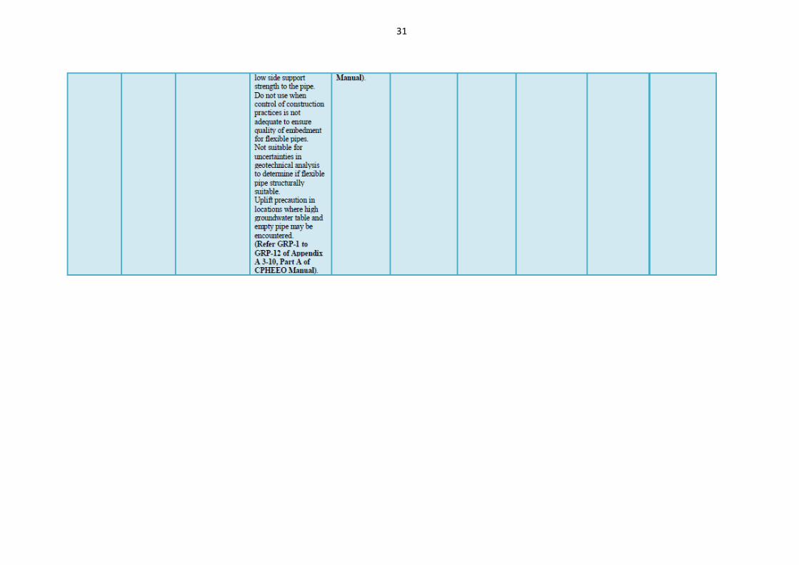
Table 5.1(As per MOWR Guidelines on PDN July.2017) provides the comparison of various types of typical Pipe Materials. However, the list of pipes available in the market is exhaustive and due to space constraints, comparisons of typical pipe materials only have been given
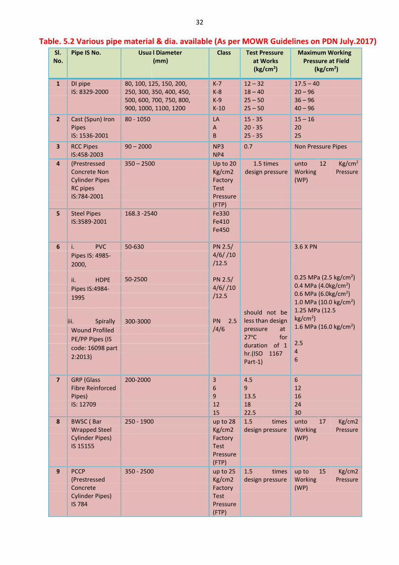
Table 5.2(As per MOWR Guidelines on PDN July.2017) provides Various pipe material & dia. available
The determination of the suitabilty in all respects of pipeline for any work is a matter of decision by the engineer concerned on the basis of requirements for the scheme.

20
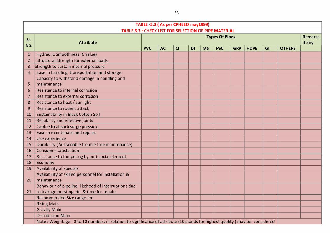
A checklist in Table 5.3(Reproduced from CPHEEO manual May 1999) for the selection of pipe material has been provided to facilitate the decision makers in selecting the economical and reliable pipe material for the given conditions. As per GR dated 02/02/2017 Chief Engineer is authoried for deciding type of pipe. However this decision needs to be taken by considering various aspects mentioned above & reasoning for pipe type selection shall be documented.
21
Table 5.1 Comparison of various Pipe Materials (As per MOWR Guidelines on PDN July.2017 )
22
23
24
25
26
27
28
29
30
31
32
Table. 5.2 Various pipe material & dia. available (As per MOWR Guidelines on PDN July.2017) Sl. No.
Pipe IS No. Usua l Diameter (mm)
Class Test Pressure
at Works (kg/cm2)
Maximum Working
Pressure at Field (kg/cm2)
1 DI pipe 80, 100, 125, 150, 200, K-7 12 – 32 17.5 – 40 IS: 8329-2000 250, 300, 350, 400, 450, K-8 18 – 40 20 – 96 500, 600, 700, 750, 800, K-9 25 – 50 36 – 96 900, 1000, 1100, 1200 K-10 25 – 50 40 – 96
2 Cast (Spun) Iron 80 - 1050 LA 15 - 35 15 – 16 Pipes A 20 - 35 20 IS: 1536-2001 B 25 - 35 25
3 RCC Pipes IS:458-2003
90 – 2000 NP3 NP4
0.7 Non Pressure Pipes
4 (Prestressed 350 – 2500 Up to 20 1.5 times unto 12 Kg/cm2 Concrete Non Kg/cm2 design pressure Working Pressure Cylinder Pipes Factory (WP) RC pipes Test IS:784-2001 Pressure (FTP)
5 Steel Pipes IS:3589-2001
168.3 -2540 Fe330 Fe410 Fe450
6 i. PVC 50-630 PN 2.5/ 4/6/ /10 /12.5
PN 2.5/ 4/6/ /10 /12.5
PN 2.5 /4/6
should not be less than design pressure at 27oC for duration of 1 hr.(ISO 1167 Part-1)
3.6 X PN
0.25 MPa (2.5 kg/cm2) 0.4 MPa (4.0kg/cm2) 0.6 MPa (6.0kg/cm2) 1.0 MPa (10.0 kg/cm2) 1.25 MPa (12.5 kg/cm2) 1.6 MPa (16.0 kg/cm2)
2.5 4 6
Pipes IS: 4985-
2000,
ii. HDPE 50-2500
Pipes IS:4984-
1995
iii.
Spirally
300-3000
Wound Profiled
PE/PP Pipes (IS
code: 16098 part
2:2013)
7 GRP (Glass 200-2000 3 4.5 6 Fibre Reinforced 6 9 12 Pipes) 9 13.5 16 IS: 12709 12 18 24 15 22.5 30
8 BWSC ( Bar 250 - 1900 up to 28 1.5 times unto 17 Kg/cm2 Wrapped Steel Kg/cm2 design pressure Working Pressure Cylinder Pipes) Factory (WP) IS 15155 Test Pressure (FTP)
9 PCCP 350 - 2500 up to 25 1.5 times up to 15 Kg/cm2 (Prestressed Kg/cm2 design pressure Working Pressure Concrete Factory (WP) Cylinder Pipes) Test IS 784 Pressure (FTP)
33
TABLE -5.3 ( As per CPHEEO may1999)
TABLE 5.3 : CHECK LIST FOR SELECTION OF PIPE MATERIAL
Sr. No.
Attribute Types Of Pipes
Remarks if any
PVC AC CI DI MS PSC GRP HDPE GI OTHERS
1 Hydraulic Smoothness (C value)
2 Structural Strength for external loads
3 Strength to sustain internal pressure
4 Ease in handling, transportation and storage
5 Capacity to withstand damage in handling and maintenance
6 Resistance to internal corrosion
7 Resistance to external corrosion
8 Resistance to heat / sunlight
9 Resistance to rodent attack
10 Sustainability in Black Cotton Soil
11 Reliability and effective joints
12 Capble to absorb surge pressure
13 Ease in maintenace and repairs
14 Use experience
15 Durability ( Sustainable trouble free maintenance)
16 Consumer satisfaction
17 Resistance to tampering by anti-social element
18 Economy
19 Availability of specials
20 Availability of skilled personnel for installation & maintenance
21 Behaviour of pipeline likehood of interruptions due to leakage,bursting etc; & time for repairs
Recommended Size range for
Rising Main
Gravity Main
Distribution Main
Note : Weightage - 0 to 10 numbers in relation to significance of attribute (10 stands for highest quality ) may be considered
34
CHAPTER VI
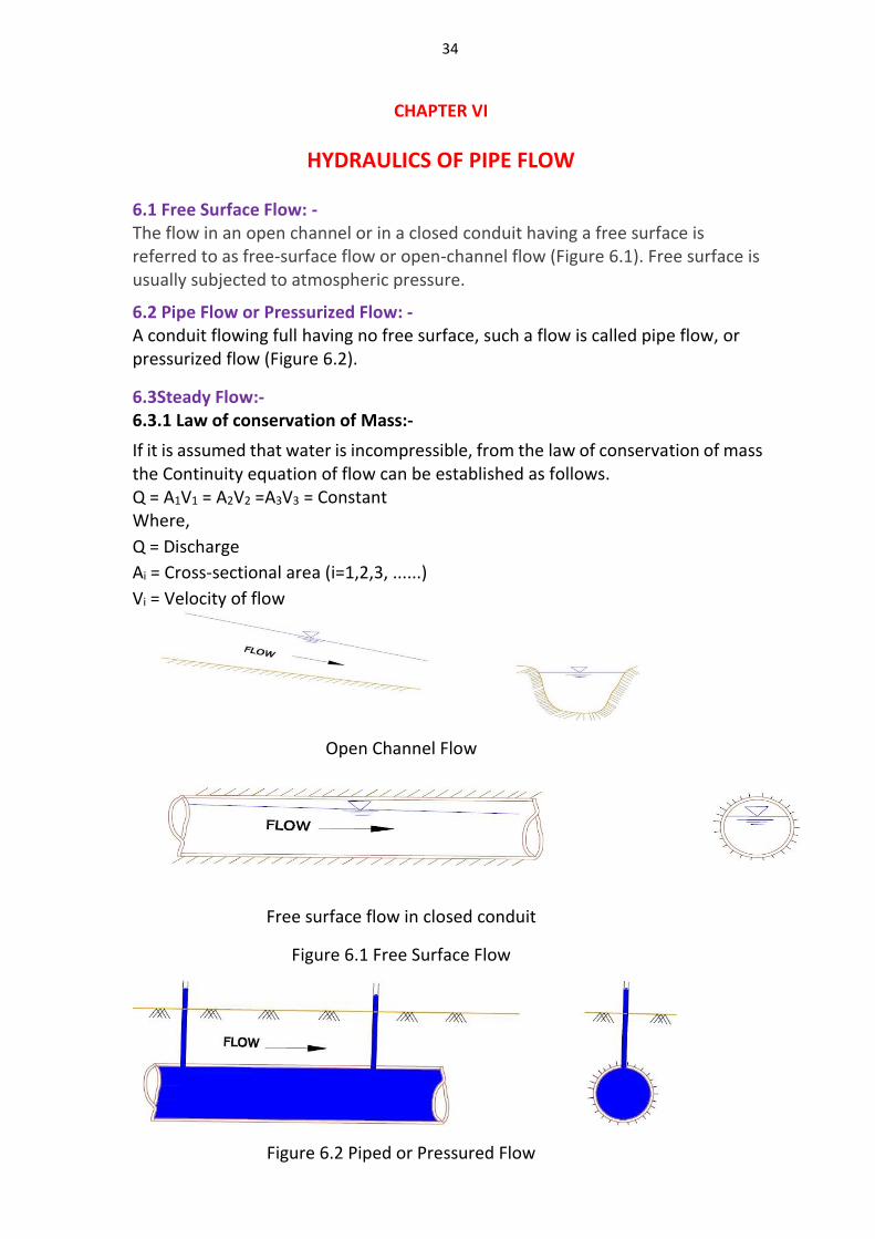
HYDRAULICS OF PIPE FLOW 6.1 Free Surface Flow: - The flow in an open channel or in a closed conduit having a free surface is referred to as free-surface flow or open-channel flow (Figure 6.1). Free surface is usually subjected to atmospheric pressure.
6.2 Pipe Flow or Pressurized Flow: - A conduit flowing full having no free surface, such a flow is called pipe flow, or pressurized flow (Figure 6.2).
6.3Steady Flow:- 6.3.1 Law of conservation of Mass:-
If it is assumed that water is incompressible, from the law of conservation of mass the Continuity equation of flow can be established as follows. Q = A1V1 = A2V2 =A3V3 = Constant Where,
Q = Discharge
Ai = Cross-sectional area (i=1,2,3, ......)
Vi = Velocity of flow
Open Channel Flow
Free surface flow in closed conduit
Figure 6.1 Free Surface Flow
Figure 6.2 Piped or Pressured Flow
35
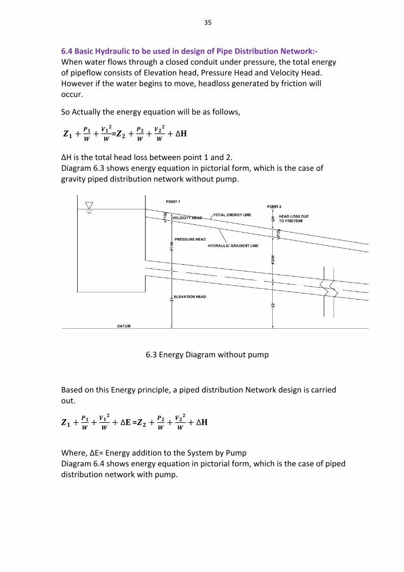
6.4 Basic Hydraulic to be used in design of Pipe Distribution Network:- When water flows through a closed conduit under pressure, the total energy of pipeflow consists of Elevation head, Pressure Head and Velocity Head. However if the water begins to move, headloss generated by friction will occur.
So Actually the energy equation will be as follows,
𝒁𝟏 +𝑷𝟏
𝑾+
𝑽𝟏𝟐
𝑾=𝒁𝟐 +
𝑷𝟐
𝑾+
𝑽𝟐𝟐
𝑾+ Δ𝐇
ΔH is the total head loss between point 1 and 2. Diagram 6.3 shows energy equation in pictorial form, which is the case of gravity piped distribution network without pump.
6.3 Energy Diagram without pump
Based on this Energy principle, a piped distribution Network design is carried out.
𝒁𝟏 +𝑷𝟏
𝑾+
𝑽𝟏𝟐
𝑾+ Δ𝐄 =𝒁𝟐 +
𝑷𝟐
𝑾+
𝑽𝟐𝟐
𝑾+ Δ𝐇
Where, ΔE= Energy addition to the System by Pump Diagram 6.4 shows energy equation in pictorial form, which is the case of piped distribution network with pump.
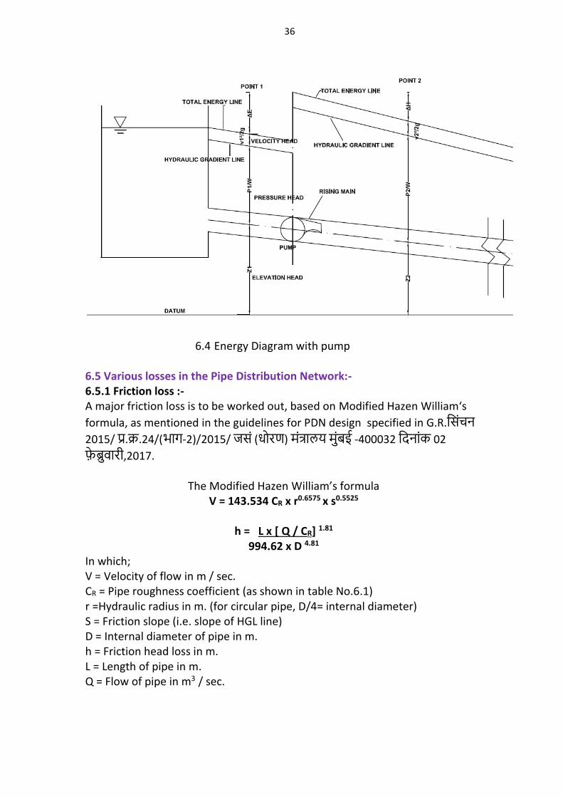
36
6.4 Energy Diagram with pump
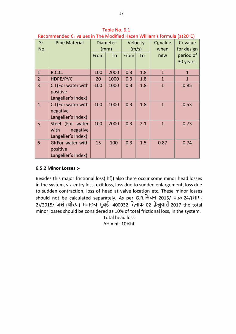
6.5 Various losses in the Pipe Distribution Network:- 6.5.1 Friction loss :- A major friction loss is to be worked out, based on Modified Hazen William‘s
formula, as mentioned in the guidelines for PDN design specified in G.R.शसिचन
2015/ पर.कर.24/(भाग-2)/2015/ जसि (धोरण) मितरालय मिबई -400032 शिनािक 02
फबरवारी,2017.
The Modified Hazen William’s formula V = 143.534 CR x r0.6575 x s0.5525
h = L x [ Q / CR] 1.81
994.62 x D 4.81 In which; V = Velocity of flow in m / sec. CR = Pipe roughness coefficient (as shown in table No.6.1) r =Hydraulic radius in m. (for circular pipe, D/4= internal diameter) S = Friction slope (i.e. slope of HGL line) D = Internal diameter of pipe in m. h = Friction head loss in m. L = Length of pipe in m. Q = Flow of pipe in m3 / sec.
37
Table No. 6.1 Recommended CR values in The Modified Hazen William‘s formula (at200C)
Sr. No.
Pipe Material Diameter (mm)
Velocity (m/s)
CR value when new
CR value for design period of 30 years.
From To From To
1 R.C.C. 100 2000 0.3 1.8 1 1
2 HDPE/PVC 20 1000 0.3 1.8 1 1
3 C.I (For water with positive Langelier’s Index)
100 1000 0.3 1.8
1 0.85
4 C.I (For water with negative Langelier’s Index)
100 1000 0.3 1.8 1 0.53
5 Steel (For water with negative Langelier’s Index)
100 2000 0.3 2.1 1 0.73
6 GI(For water with positive Langelier’s Index)
15 100 0.3 1.5 0.87 0.74
6.5.2 Minor Losses :-
Besides this major frictional loss( hf)) also there occur some minor head losses in the system, viz-entry loss, exit loss, loss due to sudden enlargement, loss due to sudden contraction, loss of head at valve location etc. These minor losses
should not be calculated separately. As per G.R.शसिचन 2015/ पर.कर.24/(भाग-
2)/2015/ जसि (धोरण) मितरालय मिबई -400032 शिनािक 02 फबरवारी,2017 the total minor losses should be considered as 10% of total frictional loss, in the system.
Total head loss ΔH = hf+10%hf
38
CHAPTER – VII
PIPE IRRIGATION NETWORK DESIGN
7.1 The hydraulic design of Pipe Distribution Network,envisages the following important points.
1. To estimate the first discharge through pipe @ the start. 2. To design the diameter of pipesinnetwork. 3. To decide the velocity of water through pipe. 4. To estimate the residual head at outlet location, above groung & above pipe
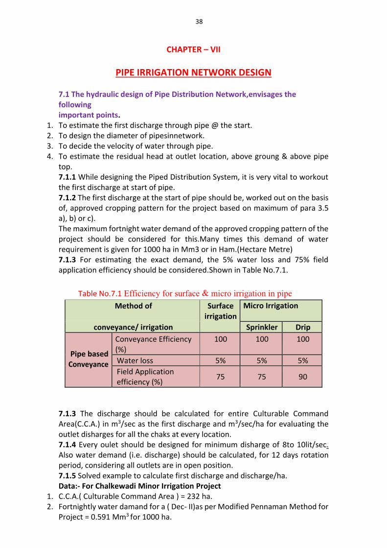
top. 7.1.1 While designing the Piped Distribution System, it is very vital to workout the first discharge at start of pipe. 7.1.2 The first discharge at the start of pipe should be, worked out on the basis of, approved cropping pattern for the project based on maximum of para 3.5 a), b) or c). The maximum fortnight water demand of the approved cropping pattern of the project should be considered for this.Many times this demand of water requirement is given for 1000 ha in Mm3 or in Ham.(Hectare Metre) 7.1.3 For estimating the exact demand, the 5% water loss and 75% field application efficiency should be considered.Shown in Table No.7.1.
Table No.7.1 Efficiency for surface & micro irrigation in pipe
Method of Surface irrigation
Micro Irrigation
conveyance/ irrigation Sprinkler Drip
Pipe based Conveyance
Conveyance Efficiency (%)
100 100 100
Water loss 5% 5% 5%
Field Application efficiency (%)
75 75 90
7.1.3 The discharge should be calculated for entire Culturable Command Area(C.C.A.) in m3/sec as the first discharge and m3/sec/ha for evaluating the outlet disharges for all the chaks at every location. 7.1.4 Every oulet should be designed for minimum disharge of 8to 10lit/sec. Also water demand (i.e. discharge) should be calculated, for 12 days rotation period, considering all outlets are in open position. 7.1.5 Solved example to calculate first discharge and discharge/ha. Data:- For Chalkewadi Minor Irrigation Project
1. C.C.A.( Culturable Command Area ) = 232 ha. 2. Fortnightly water damand for a ( Dec- II)as per Modified Pennaman Method for
Project = 0.591 Mm3 for 1000 ha.
39
The water demand is given in Mm3 and it is for 1000 ha, The C.C.A. for the Chalkewadi Project is = 232 ha.
Hence water demand Volume for this area = 0.591X10⁶ (m3) x232 (ha)/1000 (ha) =137112 (m3) (This Net volume of water is required for Dec-IInd fortninght at outlet location and that is to be discharged continuously in 12 days) The above volume of water is to be increased by 5% for water loss and 75% for Field Application Efficiecy
Hence Gross Volume of water required = 137112 x 1.05 0.75 = 191956.80 ≈ 191957 m3
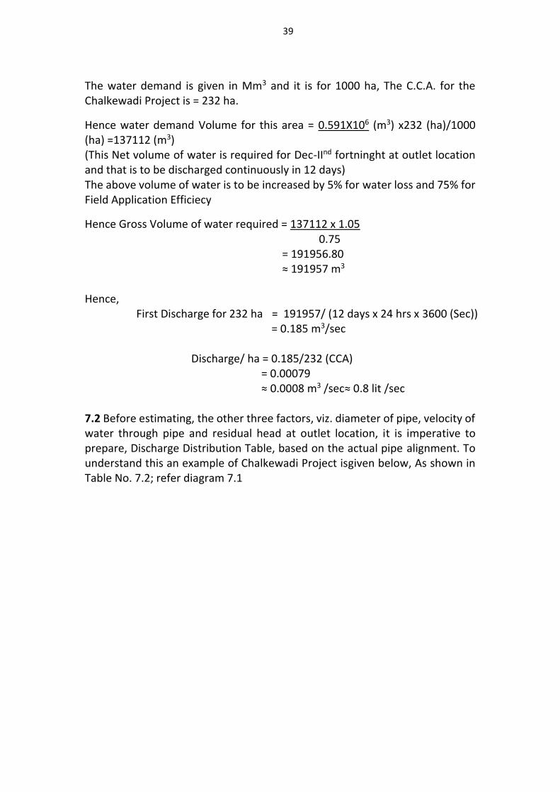
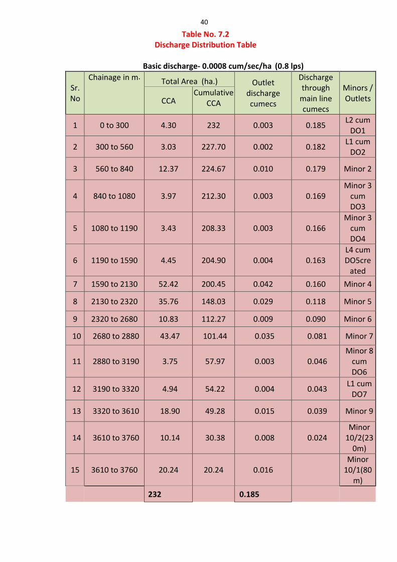
Hence, First Discharge for 232 ha = 191957/ (12 days x 24 hrs x 3600 (Sec)) = 0.185 m3/sec Discharge/ ha = 0.185/232 (CCA) = 0.00079 ≈ 0.0008 m3 /sec≈ 0.8 lit /sec 7.2 Before estimating, the other three factors, viz. diameter of pipe, velocity of water through pipe and residual head at outlet location, it is imperative to prepare, Discharge Distribution Table, based on the actual pipe alignment. To understand this an example of Chalkewadi Project isgiven below, As shown in Table No. 7.2; refer diagram 7.1
40
Table No. 7.2 Discharge Distribution Table
Basic discharge- 0.0008 cum/sec/ha (0.8 lps)
Sr. No
Chainage in m . Total Area (ha.) Outlet discharge cumecs
Discharge through
main line cumecs
Minors / Outlets CCA
Cumulative CCA
1 0 to 300 4.30 232 0.003 0.185 L2 cum
DO1
2 300 to 560 3.03 227.70 0.002 0.182 L1 cum
DO2
3 560 to 840 12.37 224.67 0.010 0.179 Minor 2
4 840 to 1080 3.97 212.30 0.003 0.169 Minor 3
cum DO3
5 1080 to 1190 3.43 208.33 0.003 0.166 Minor 3
cum DO4
6 1190 to 1590 4.45 204.90 0.004 0.163 L4 cum DO5cre
ated
7 1590 to 2130 52.42 200.45 0.042 0.160 Minor 4
8 2130 to 2320 35.76 148.03 0.029 0.118 Minor 5
9 2320 to 2680 10.83 112.27 0.009 0.090 Minor 6
10 2680 to 2880 43.47 101.44 0.035 0.081 Minor 7
11 2880 to 3190 3.75 57.97 0.003 0.046 Minor 8
cum DO6
12 3190 to 3320 4.94 54.22 0.004 0.043 L1 cum
DO7
13 3320 to 3610 18.90 49.28 0.015 0.039 Minor 9
14 3610 to 3760 10.14 30.38 0.008 0.024 Minor
10/2(230m)
15 3610 to 3760 20.24 20.24 0.016 Minor
10/1(80m)
232 0.185
41
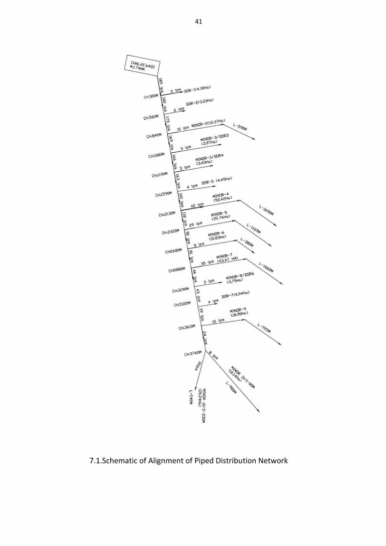
7.1.Schematic of Alignment of Piped Distribution Network
42
7.2.1 Now Look @ the Pipe line alignment diagram above, where the first discharge of 0.185 m3/sec (185lps) is shown, up to 300m length. At CH.300m,there is one direct outlet, which irrigates the area of, 4.30 ha, for which outlet discharge can be worked out = 4.3 ha x 0.0008 m3/sec/ha = 0.00344 m3/Sec = 3 lps Now from the chainage 300 m onwards, the total discharge which will flow in the main pipe line, up to 560m. = (0.185-0.00344) m3/sec = 0.182 m3/sec In this manner, the discharges in the entire command area, for all the outlets can be worked out. Thus by adopting the aforesaid procedure, the Discharge Distribution for, the entire Network can be prepared, which is shown in Table 7.2. The remaining three Parameters viz- Pipe Diameter, Velocity of Water through Pipe and Residual Head can be worked out through Excel program
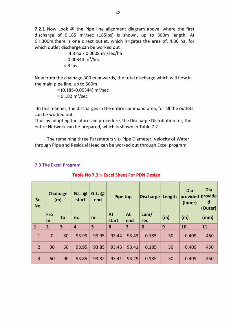
7.3 The Excel Program
Table No 7.3 :- Excel Sheet For PDN Design
Sr. No.
Chainage (m)
G.L. @ start
G.L. @ end
Pipe top Discharge Length Dia
provided (Inner)
Dia provide
d (Outer)
From
To m. m. At start
At end
cum/ sec
(m) (m) (mm)
1 2 3 4 5 6 7 8 9 10 11
1 0 30 93.99 93.95 93.44 93.43 0.185 30 0.409 450
2 30 60 93.95 93.85 93.43 93.41 0.185 30 0.409 450
3 60 90 93.85 93.82 93.41 93.29 0.185 30 0.409 450
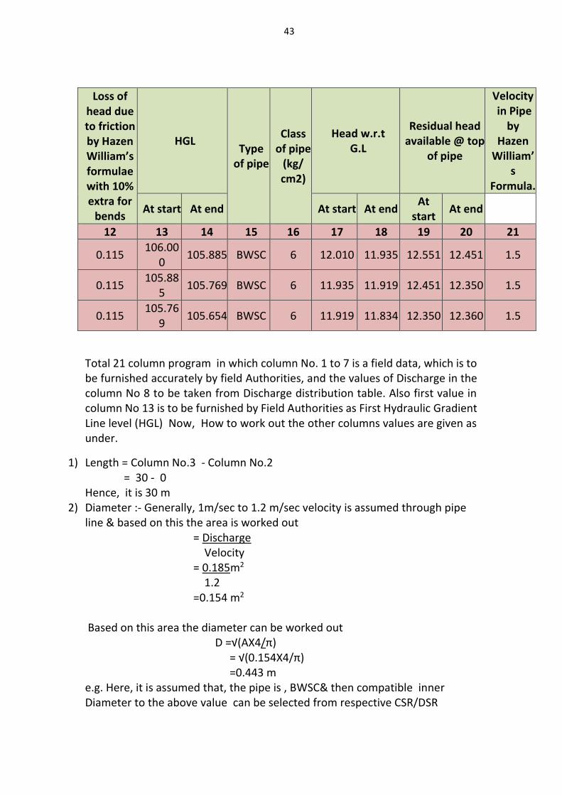
43
Loss of head due to friction by Hazen William’s formulae with 10% extra for
bends
HGL Type
of pipe
Class of pipe
(kg/ cm2)
Head w.r.t G.L
Residual head available @ top
of pipe
Velocity in Pipe
by Hazen
William’s
Formula.
At start At end At start At end At
start At end
12 13 14 15 16 17 18 19 20 21
0.115 106.00
0 105.885 BWSC 6 12.010 11.935 12.551 12.451 1.5
0.115 105.88
5 105.769 BWSC 6 11.935 11.919 12.451 12.350 1.5
0.115 105.76
9 105.654 BWSC 6 11.919 11.834 12.350 12.360 1.5
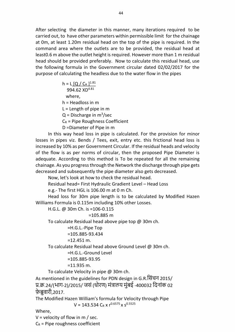
Total 21 column program in which column No. 1 to 7 is a field data, which is to be furnished accurately by field Authorities, and the values of Discharge in the column No 8 to be taken from Discharge distribution table. Also first value in column No 13 is to be furnished by Field Authorities as First Hydraulic Gradient Line level (HGL) Now, How to work out the other columns values are given as under.
1) Length = Column No.3 - Column No.2 = 30 - 0 Hence, it is 30 m
2) Diameter :- Generally, 1m/sec to 1.2 m/sec velocity is assumed through pipe line & based on this the area is worked out = Discharge Velocity = 0.185m2 1.2 =0.154 m2 Based on this area the diameter can be worked out D =√(AX4/π) = √(0.154X4/π) =0.443 m e.g. Here, it is assumed that, the pipe is , BWSC& then compatible inner Diameter to the above value can be selected from respective CSR/DSR
44
After selecting the diameter in this manner, many iterations required to be carried out, to have other parameters within permissible limit for the chainage at 0m, at least 1.20m residual head on the top of the pipe is required. In the command area where the outlets are to be provided, the residual head at least0.6 m above the outlet height is required. However more than 1 m residual head should be provided preferably. Now to calculate this residual head, use the following formula in the Government circular dated 02/02/2017 for the purpose of calculating the headless due to the water flow in the pipes
h = L [Q / CR ]1.81 994.62 XD4.81
where, h = in m Headloss L = Length of pipe in m Q = Discharge in m3/sec CR = Pipe Roughness Coefficient D =Diameter of Pipe in m
In this way head loss in pipe is calculated. For the provision for minor losses in pipes viz. Bends / Tees, exit, entry etc. this frictional head loss is increased by 10% as per Government Circular. If the residual heads and velocity of the flow is as per norms of circular, then the proposed Pipe Diameter is adequate. According to this method is To be repeated for all the remaining chainage. As you progress through the Network the discharge through pipe gets decreased and subsequently the pipe diameter also gets decreased.
Now, let's look at how to check the residual head. Residual head= First Hydraulic Gradient Level – Head Loss e.g.- The first HGL is 106.00 m at 0 m Ch. Head loss for 30m pipe length is to be calculated by Modified Hazen
Williams Formula is 0.115m including 10% other Losses. H.G.L. @ 30m Ch. is =106-0.115 =105.885 m To calculate Residual head above pipe top @ 30m ch.
=H.G.L.-Pipe Top =105.885-93.434 =12.451 m.
To calculate Residual head above Ground Level @ 30m ch. =H.G.L.-Ground Level =105.885-93.95 =11.935 m.
To calculate Velocity in pipe @ 30m ch.
As mentioned in the guidelines for PDN design in G.R.शसिचन 2015/
पर.कर.24/(भाग-2)/2015/ जसि (धोरण) मितरालय मिबई -400032 शिनािक 02
फबरवारी,2017. The Modified Hazen William’s formula for Velocity through Pipe V = 143.534 CR x r0.6575 x s0.5525 Where, V = velocity of flow in m / sec. CR = Pipe roughness coefficient
45
r = Hydraulic radius in m. (for circular pipe, d/4= internal diameter) S = Frictions slope (i.e. slope of HGL line) =hf/L d = Internal diameter of pipe in m. hf = Friction head loss in m. L = Length of pipe in m.
Now, V =? CR =1
d= 1.5 m. hf =0.115 m. L= 30 V = 143.534 X1 X (1.5/4) 0.6575 X (0.115/30) 0.5525 = 1.5 m/sec.
The CR value is given in the previous chapter as Table No 6.1.
7.4 SELECTION OF PIPE TYPE- In the Pipe distribution system, the role of selection of type of pipe is vital, in order to keep the cost of Pipe Network as minimum as possible. There are various types of pipes in that commonly used as MS pipe, PCCP, CI, DI, HDPE, PVC. For this, the following factors should be taken into consideration.
1. Modified Hazen William ‘s Coefficient (C) 2. The inner and outer pressure in pipe 3. The durability of pipe material. 4. The ease of jointing and durability at workplace, as design life span for pipe
distribution network is considered as 50years. 5. Ease of availability of many types of diameter and its viability. 6. Availability of skilled workers for setting up at work place. 7. The pipes and its fittings should be easy. 8. Fittings should also be able to tolerate the pressure of water in the pipes. 9. If the soil in which the sulfate content is more than 1%, then do not use metal
pipes and cement pipes. (For detail information refer CWC Manual (July 2017) Guidelines for Planning & Design of Piped Irrigation Network, Page no.32 to 43.
46
CHAPTER –VIII
USE OF SOFTWARE FOR PDN DESIGN For the design of Piped Distribution Network for irrigation mainly following software Program are used.
1. EPANET 2. Water GEMS 3. M.S. EXCEL Sheet 8.1 EPANET
EPANET is a public domain, water distribution system modeling software package developed by the United States Environmental Protection Agency's (EPA) Water Supply and Water Resources Division. It performs extended-period simulation of hydraulic and water-quality behavior within pressurized pipe networks and is designed to be "a research tool that improves our understanding of the movement and fate of drinking/irrigation water constituents within distribution systems".
EPANET 2 is available both as a standalone program and as an open-source toolkit (Application Programming Interface in C). Its computational engine is used by many software companies that developed more powerful, proprietary packages, often GIS-centric.
8.1.1 FEATURES 1. EPANET hydraulics engine computes head losses along the pipes by using one
of the three formulas:
A. Hazen-Williams formula: used to model full flow conditions under simplified conditions
B. Darcy-Weisbach formula: used to model pressurized flow under a broader range of hydraulic conditions
C. Chezy-Manning formula: used to model pressurized flow by using Chezy's roughness coefficients for Manning's equation
Since the pipe segment head loss equation is used within the network solver, the formula above is selected for the entire model
2. The visual network editor of EPANET simplifies the process of building piping network models and editing their properties. These various types of data reporting visualization tools are used to assist to analyze the networks, which include the graphics views, tabular views, and special reports.
3. EPANET provides an integrated environment for editing network input data, running hydraulic and water quality simulations, and viewing the results in a variety of formats
4. EPANET provides a fully equipped and extended period of hydraulic analysis that can handle systems of any size.
47
5. The package also supports the simulation of spatially and temporally varying water demand, constant or variable speed pumps, and the minor head losses for bends and fittings.
6. The modeling provides information such as flows in pipes, pressures at junctions, propagation of a contaminant, chlorine concentration, water age, and even alternative scenario analysis. This helps to compute pumping energy and cost and then model various types of valves, including shutoffs, check pressure regulating and flow control.
8.1.2 INPUT DATA FORMAT
1. EPANET uses a binary file format, but also includes the capability for importing and exporting data in dxf, metafile, and ASCII file formats.
2. EPANET's ASCII file format is called an input file within EPANET, and uses a file extension ".inp".The input file can include data describing network topology, water consumption, and control rules, and is supported by many free and commercial modeling packages.
3. While EPANET is used as the computational engine for most water distribution system models, most models (KYPipe, WaterCAD, WaterGEMS, HAMMER and SewerCAD)are developed and maintained in hydraulic modeling packages based on EPANET's computational engine.
8.1.3 OBSERVATIONS
Presently Central Design Organization's PDN design wing is using EPANET. In most of the cases survey (command area) data available for PDN design is very old ( In the form of toposheets). For PDN design in EPANET, it is required to fill ground level of all junctions as well as pipe diameter, pipe length, pipe mateial of each pipe section which is very leangthy and time taking procedure. This software carries out only head loss calculations and gives new hydraulic gradient level and velocity values. So this software only partially helpful for design of PDN network.This software based on Hazen-Williams formula (old). Due to manual feeding of data mistakes may occurs.There is no drawing output.
8.2 Water GEMS
Water GEMS is a hydraulic modeling application for water distribution systems with advanced interoperability, geospatial model building, optimization, and asset management tools, Water GEMS provides an easy to use environment for engineers to analyze, design, and optimize water distribution systems.
8.2.1 FEATURES
1. In Water GEMS geospatial data, CAD drawings, databases, and spreadsheets can be use for model building process. Water GEMS provides synchronized database connections, geospatial links, and advanced model-building modules that connect with format virtually any digital data
2. Water GEMS includes Demand Control Centre to allocate Water demand for each junction and TRex module to allocate node elevation based
on geospatial data found in shape file, geodatabases, various types of DEMs, and even CAD drawings. These modules help engineers avoid potential manual-
48
input mistakes. Water GEMS also provides drawing and connectivity review tools to guarantee a hydraulically coherent model. This automatically removes network complexity, while maintaining hydraulic equivalence, to efficiently tackle a wider range of modeling applications
3. WaterGEMS includes Darwin Designer Tool in which synchronized database connection of junctions and pipe with allocated water demand and node elevation system of piped distribution network, the diameter can be automatically get selected within the range of given pipe diameter range and pipe material. This tool is important and useful for optimization of pipe diameter.
4. Darwin Calibrator evaluates millions of possible solutions to let users quickly find a calibration hypothesis that best matches measured flows, pressures, and on/off status, empowering users to make reliable decisions based on accurate hydraulic simulations of the real world.
5. Darwin Designer automatically finds maximum benefit or minimum-cost designs and rehabilitation strategies, based on available budget, construction cost, and pressure and velocity constraints.
6. In WaterGEMS a special tool named as Scenario & Alternative which allows multiple demand conditions, various pump position, various valve positions, piped distribution network with and without pump, can be use. It makes easy interpretation of results with different conditions. Data feed for piped distribution network can be used for each different condition.
7. WaterGEMS includes state-of-the-art genetic algorithm optimization engines for automated calibration, design and rehabilitation, and pump operations.
8. WaterGEMS’ SCADAConnect® module lets modelers automatically acquire supervisory control and data acquisition (SCADA) data, creating a real-time system simulator that accurately represents current system conditions.
9. WaterGEMS model results to be published to a utility’s existing SCADA control room screen(s), helping to forecast operating conditions and potential issues.
8.2.2 INPUT DATA FORMAT
DGN, DXF, spreadsheet, database, and ODBC connections
Shapefile, geodatabase*, Geometric Network*, and SDE* connections (*when running from within ArcMap)
Oracle Spatial support
GIS-ID property to maintain associations between records in the data source / GIS and elements in the model
SCADAConnect 25-signal pack for live data connections (to and from SCADA systems)
Graphical SCADA element
Customer Meter element
Lateral link (no need to split pipes)
49
Automatic demand allocation from geospatial data
Geospatial demand allocation from customer meters
Demand allocation from lump-sum geospatial data
Geospatial-based water consumption projection
Daily, weekly, monthly, and superimposed patterns
Unaccounted for water and leakage estimation
Composite demands global edition
Area, count, discharge, and population-based loading
Pipe-length-based demand loading
Elevation extraction from DEM, TIN, and shape files
Elevation extraction from CAD drawings and surfaces
Series, parallel, branch-trimming, multi-criteria automated skeletonization of pipes
Skeletonization support for isolation valves
User-data extension, including formula based
8.2.3 Model Management
Unlimited scenarios and alternatives
Comprehensive scenario management
Global attribute tabular edition
Pressure zone management
Automated model skeletonization
Personalizable engineering libraries
Sorting and persistent filtering on tabular reports
Statistical analysis from tabular reports
Dynamic and static selection sets
Local and global engineering-units management
Sub-model management
Drawing review tools for connectivity consistency
Automatic topology review
Orphaned nodes and dead-end pipes queries
8.2.4 Interoperability, Interface, and Graphical Editing
Runs from within four compatible platforms:
Stand-alone Windows
ArcGIS (ArcMap license required)
Micro Station (Micro Station license required)
50
AutoCAD (AutoCAD license required)
Unlimited undo and redo
Element morphing, splitting, and reconnection
Merge nodes in close proximity tool
Automatic element labeling
Scaled, schematic, and hybrid environments
Element prototypes
Aerial view and dynamic zooming
Named views library
Multiple background-layer support
8.2.5 OBSERVATIONS
At present central Design Organization PDN design wing has one Water GEMS software loaded in their computer lab. This software is based on GIS platform so all the input data of survey should be in synchronous with GIS. Command area survey should be carried out with the help of total station or Drone. In this survey atleast three points have reference with universal transverse Mercator (UTM) co-ordinate system. With the help of these reference points the whole piped distribution network can be mapped on Google Earth. Many more alternatives can be found out from this survey data. When command area drawing prepared from this data the countour (contour interval 2to 5m) plotted should be alloted with z co-ordinate or Elevation value in autocad drawing. It is easy to import such autocad file in form of .dfx to Water GEMS with the help of TRex tool. Command area drawing can be imported as background layer in Water GEMS.
As mentioned above, unless data is not received in proper format the use of Water GEMS for different scenarios and optimization of pipe by diameter is not possible. Hence if the design is to be done by Water GEMS the command survey should be carried out either by total station or drone.
8.3 M.S. EXCEL SHEET
Piped distribution network design with the help of M.S.Excel Sheet the following data need to be filled and first pipe diameter is assumed and required constraints such as length, head loss,velocity, Hydraulic Gradient level and residual head is worked out. (Detailed procedure given in Chapter No VII)
1. Ground Level along the PDN alignment approximately 20m or 30m interval is to be filled. It helps to understand the ground profile of command area to make the laying of pipe easily.
2. Discharge at each pipe section is to be filled.
3. Head loss and Velocity in the given pipe section is calculated by Modified Hazen-Williams formula.
51
For the provision for minor losses in pipes viz. Bends / Tees, exit, entry etc. this frictional head loss is increased by 10% as per Government Circular. If the residual heads and velocity of the flow is as per norms of circular, dtd 02/02/2017 then the proposed Pipe Diameter is adequate. Accordingly, this method is to be repeated for all the remaining chainages. As you progress through the Network the discharge through pipe gets decreased and subsequently the pipe diameter also gets decreased.
If the alignment of pipeline in the command are properly laid on the command map i.e. minimum length of pipe is laid to cover entire command area; The results achieved from excel sheet are quite satisfactory and economical because in the PDN design basic parameter which influences cost is difference between start HGL and outlet ground level so with the available head, we have to arrange pipes telescopically from start to outlet location. This is the basic approach to the design. Hence if we go by this theme whatever the method or software we use will have marginal impact on the final outcome.
52
CHAPTER – IX
VALVES AND BLOCKS
Valves play a critical role in a water distribution system for subsystem isolation(due to breakage or contaminant) and flow or pressure control. Main type of valves are i) Gate valve ii) Check valve iii) Drain valve iv) Air release valve v) Pressure regulating valve vi) Pressure reducing valve. 9.1 VALVES
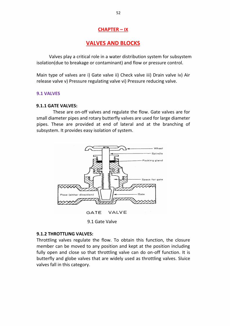
9.1.1 GATE VALVES: These are on-off valves and regulate the flow. Gate valves are for
small diameter pipes and rotary butterfly valves are used for large diameter pipes. These are provided at end of lateral and at the branching of subsystem. It provides easy isolation of system.
9.1 Gate Valve
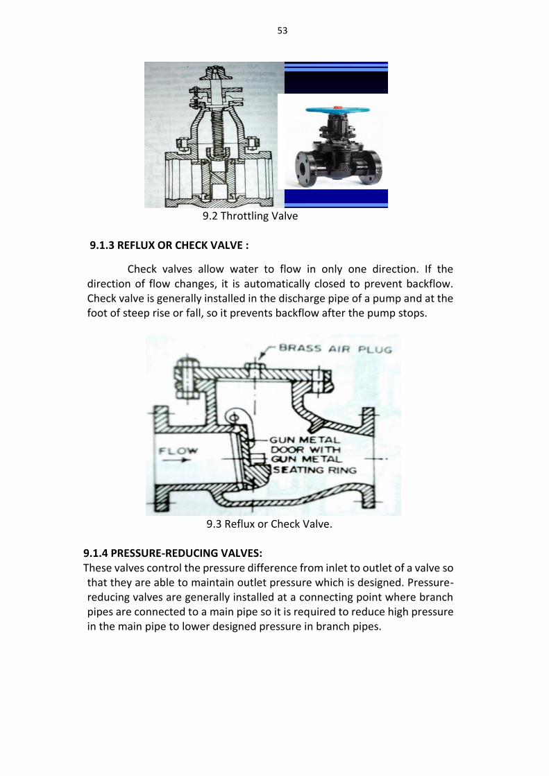
9.1.2 THROTTLING VALVES: Throttling valves regulate the flow. To obtain this function, the closure member can be moved to any position and kept at the position including fully open and close so that throttling valve can do on-off function. It is butterfly and globe valves that are widely used as throttling valves. Sluice valves fall in this category.
53
9.2 Throttling Valve
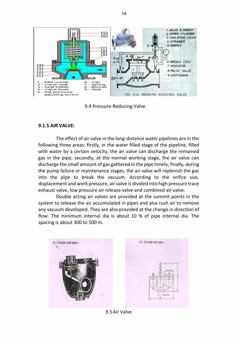
9.1.3 REFLUX OR CHECK VALVE :
Check valves allow water to flow in only one direction. If the direction of flow changes, it is automatically closed to prevent backflow. Check valve is generally installed in the discharge pipe of a pump and at the foot of steep rise or fall, so it prevents backflow after the pump stops.
9.3 Reflux or Check Valve.
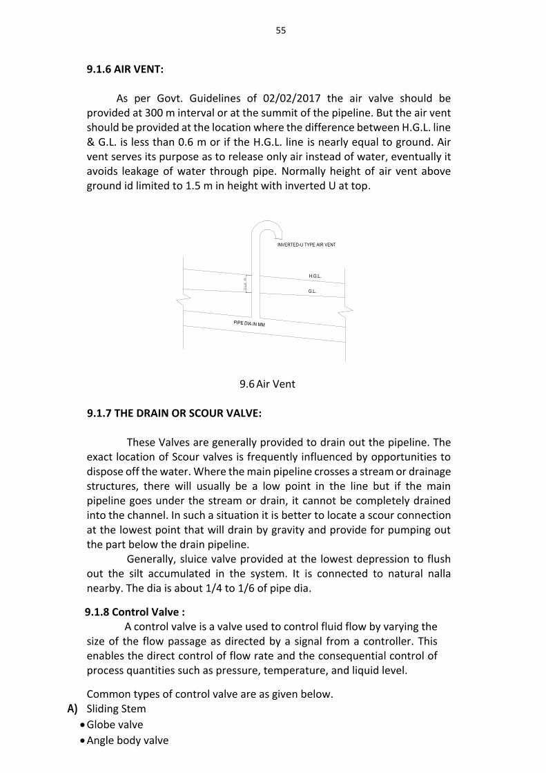
9.1.4 PRESSURE-REDUCING VALVES:
These valves control the pressure difference from inlet to outlet of a valve so that they are able to maintain outlet pressure which is designed. Pressure-reducing valves are generally installed at a connecting point where branch pipes are connected to a main pipe so it is required to reduce high pressure in the main pipe to lower designed pressure in branch pipes.
54
9.4 Pressure-Reducing Valve.
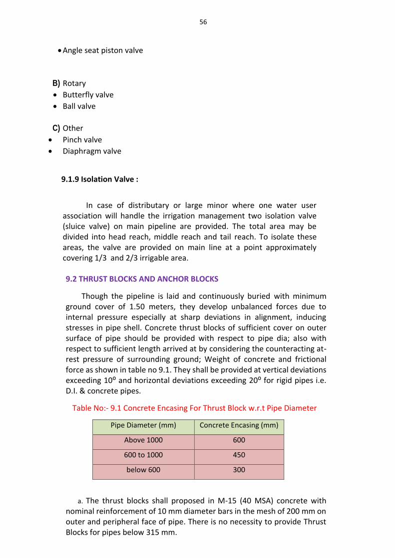
9.1.5 AIR VALVE:
The effect of air valve in the long-distance water pipelines are in the following three areas: firstly, in the water filled stage of the pipeline, filled with water by a certain velocity, the air valve can discharge the remained gas in the pipe; secondly, at the normal working stage, the air valve can discharge the small amount of gas gathered in the pipe timely; finally, during the pump failure or maintenance stages, the air valve will replenish the gas into the pipe to break the vacuum. According to the orifice size, displacement and work pressure, air valve is divided into high pressure trace exhaust valve, low pressure air release valve and combined air valve.
Double acting air valves are provided at the summit points in the system to release the air accumulated in pipes and also rush air to remove any vacuum developed. They are also provided at the change in direction of flow. The minimum internal dia is about 10 % of pipe internal dia. The spacing is about 300 to 500 m.
9.5 Air Valve
55
9.1.6 AIR VENT: As per Govt. Guidelines of 02/02/2017 the air valve should be provided at 300 m interval or at the summit of the pipeline. But the air vent should be provided at the location where the difference between H.G.L. line & G.L. is less than 0.6 m or if the H.G.L. line is nearly equal to ground. Air vent serves its purpose as to release only air instead of water, eventually it avoids leakage of water through pipe. Normally height of air vent above ground id limited to 1.5 m in height with inverted U at top.
9.6 Air Vent
9.1.7 THE DRAIN OR SCOUR VALVE:
These Valves are generally provided to drain out the pipeline. The exact location of Scour valves is frequently influenced by opportunities to dispose off the water. Where the main pipeline crosses a stream or drainage structures, there will usually be a low point in the line but if the main pipeline goes under the stream or drain, it cannot be completely drained into the channel. In such a situation it is better to locate a scour connection at the lowest point that will drain by gravity and provide for pumping out the part below the drain pipeline.
Generally, sluice valve provided at the lowest depression to flush out the silt accumulated in the system. It is connected to natural nalla nearby. The dia is about 1/4 to 1/6 of pipe dia.
9.1.8 Control Valve : A control valve is a valve used to control fluid flow by varying the size of the flow passage as directed by a signal from a controller. This enables the direct control of flow rate and the consequential control of process quantities such as pressure, temperature, and liquid level.
Common types of control valve are as given below. A) Sliding Stem
Globe valve
Angle body valve
PIPE DIA IN MM
H.G.L.
G.L.
INVERTED-U TYPE AIR VENT
56
Angle seat piston valve
B) Rotary
Butterfly valve
Ball valve
C) Other
Pinch valve
Diaphragm valve
9.1.9 Isolation Valve :
In case of distributary or large minor where one water user association will handle the irrigation management two isolation valve (sluice valve) on main pipeline are provided. The total area may be divided into head reach, middle reach and tail reach. To isolate these areas, the valve are provided on main line at a point approximately covering 1/3 and 2/3 irrigable area. 9.2 THRUST BLOCKS AND ANCHOR BLOCKS
Though the pipeline is laid and continuously buried with minimum ground cover of 1.50 meters, they develop unbalanced forces due to internal pressure especially at sharp deviations in alignment, inducing stresses in pipe shell. Concrete thrust blocks of sufficient cover on outer surface of pipe should be provided with respect to pipe dia; also with respect to sufficient length arrived at by considering the counteracting at-rest pressure of surrounding ground; Weight of concrete and frictional force as shown in table no 9.1. They shall be provided at vertical deviations exceeding 10⁰ and horizontal deviations exceeding 20⁰ for rigid pipes i.e. D.I. & concrete pipes.
Table No:- 9.1 Concrete Encasing For Thrust Block w.r.t Pipe Diameter
Pipe Diameter (mm) Concrete Encasing (mm)
Above 1000 600
600 to 1000 450
below 600 300
a. The thrust blocks shall proposed in M-15 (40 MSA) concrete with nominal reinforcement of 10 mm diameter bars in the mesh of 200 mm on outer and peripheral face of pipe. There is no necessity to provide Thrust Blocks for pipes below 315 mm.
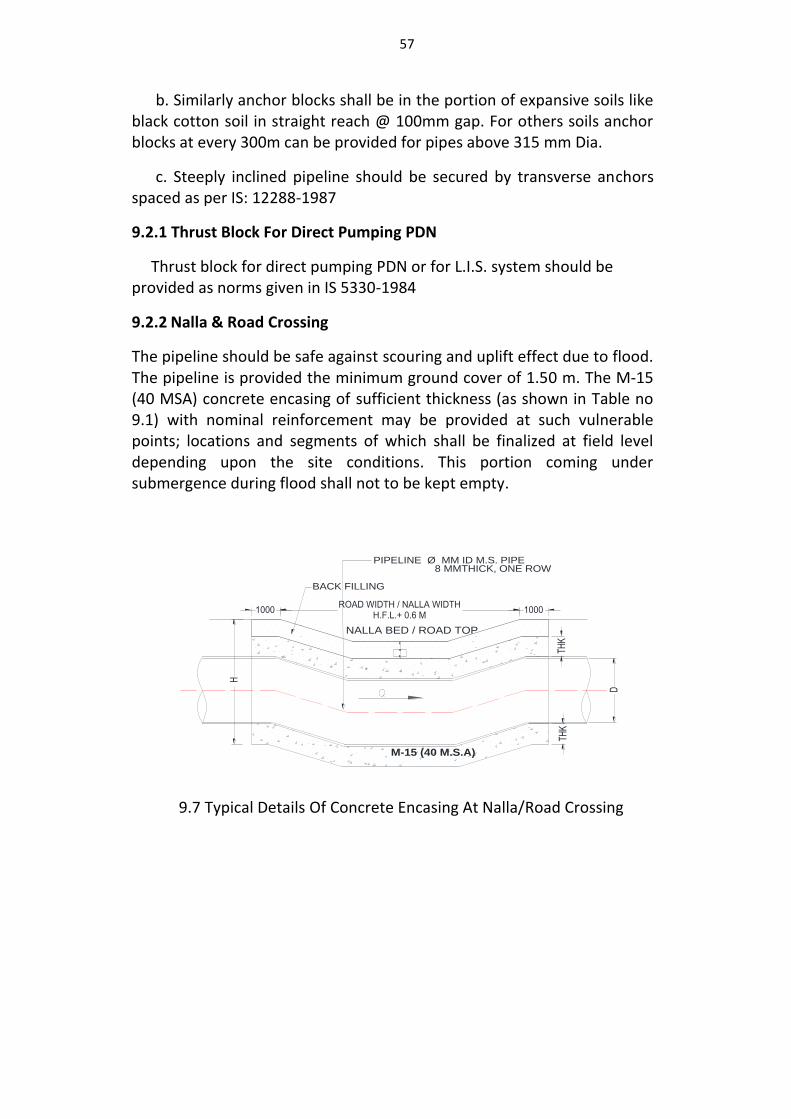
57
b. Similarly anchor blocks shall be in the portion of expansive soils like black cotton soil in straight reach @ 100mm gap. For others soils anchor blocks at every 300m can be provided for pipes above 315 mm Dia.
c. Steeply inclined pipeline should be secured by transverse anchors spaced as per IS: 12288-1987
9.2.1 Thrust Block For Direct Pumping PDN
Thrust block for direct pumping PDN or for L.I.S. system should be provided as norms given in IS 5330-1984
9.2.2 Nalla & Road Crossing
The pipeline should be safe against scouring and uplift effect due to flood. The pipeline is provided the minimum ground cover of 1.50 m. The M-15 (40 MSA) concrete encasing of sufficient thickness (as shown in Table no 9.1) with nominal reinforcement may be provided at such vulnerable points; locations and segments of which shall be finalized at field level depending upon the site conditions. This portion coming under submergence during flood shall not to be kept empty.
9.7 Typical Details Of Concrete Encasing At Nalla/Road Crossing
BACK FILLING
ROAD WIDTH / NALLA WIDTHH.F.L.+ 0.6 M
1000 1000
NALLA BED / ROAD TOP
THK
PIPELINE Ø MM ID M.S. PIPE8 MMTHICK, ONE ROW
M-15 (40 M.S.A)
THK
D
H
58
CHAPTER –X
SPECIFICATION FOR VARIOUS TYPES OF PIPES
1.0 The following types of pipes are commonly used in the pipe distribution network. a. High density Polyethylene Pipe (HDPE) b. Spirally Wound Steel Reinforced Pipe (SWSRP) c. Polyvinyl Chloride Pipe (PVC) d. Oriented Unplasticized Polyvinyl Chloride Pipe (PVC- O) e. Glass Fiber Reinforced Plastic Pipe (GRP) f. Prestressed Concrete Non-cylinder Pipe (PSC) g. Pre-stressed Concrete Cylinder Pipe (PCCP) h. Bar/wire wrapped steel cylinder pipe (BWSC) i. Mild steel pipes (M S) j. Ductile iron pipes (DI)
2.0 Vide Water Resources Department's governance circular no.
Sinchan 2015/case no-24.2(Part- 2)/2015/WR (Policy) dated 02/02/2017, guidelines are issued to adopt entire or partial pipe distribution system for the distribution network of irrigation projects. Chief Engineer is authorized to decide the type of pipe for distribution system based on various parameters such as discharge, pressure, cost, etc.
3.0 While formulating specifications for each pipe type, provisions prescribed in guidelines laid down by Central Water Commission (Guidelines for Planning and Design of piped irrigation network, July 2017) and various Indian standards, codes are considered.
4.0 Specifications for various pipes cover following aspects.
1.0 Introduction
2.0 Applicable IS Codes
3.0 Raw Material
4.0 Manufacturing Pipes and Specials
5.0 Sampling Criteria for Selection of Pipes for Testing Purpose
6.0 Pre Delivery Testing of Pipes
7.0 Marking on Pipes
8.0 Transportation of Pipes
9.0 Stacking of Pipes at Site
10.0 Valves
11.0 Post Delivery Testing of Pipes
12.0 Site Preparation
13.0 Excavation for Pipe Trenches
14.0 Laying of pipes
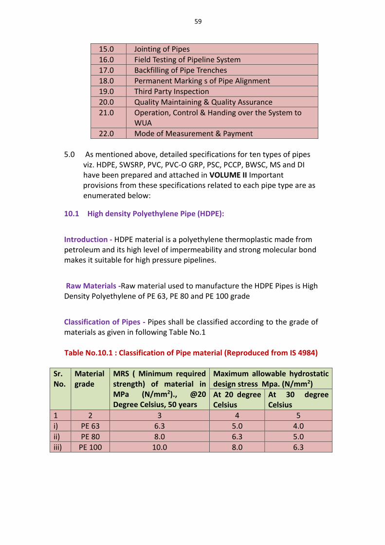
59
15.0 Jointing of Pipes
16.0 Field Testing of Pipeline System
17.0 Backfilling of Pipe Trenches
18.0 Permanent Marking s of Pipe Alignment
19.0 Third Party Inspection
20.0 Quality Maintaining & Quality Assurance
21.0 Operation, Control & Handing over the System to WUA
22.0 Mode of Measurement & Payment
5.0 As mentioned above, detailed specifications for ten types of pipes
viz. HDPE, SWSRP, PVC, PVC-O GRP, PSC, PCCP, BWSC, MS and DI have been prepared and attached in VOLUME II Important
provisions from these specifications related to each pipe type are as enumerated below:
10.1 High density Polyethylene Pipe (HDPE):
Introduction - HDPE material is a polyethylene thermoplastic made from petroleum and its high level of impermeability and strong molecular bond makes it suitable for high pressure pipelines.
Raw Materials -Raw material used to manufacture the HDPE Pipes is High Density Polyethylene of PE 63, PE 80 and PE 100 grade
Classification of Pipes - Pipes shall be classified according to the grade of materials as given in following Table No.1 Table No.10.1 : Classification of Pipe material (Reproduced from IS 4984)
Sr. No.
Material grade
MRS ( Minimum required strength) of material in MPa (N/mm2)., @20 Degree Celsius, 50 years
Maximum allowable hydrostatic design stress Mpa. (N/mm2)
At 20 degree Celsius
At 30 degree Celsius
1 2 3 4 5
i) PE 63 6.3 5.0 4.0
ii) PE 80 8.0 6.3 5.0
iii) PE 100 10.0 8.0 6.3
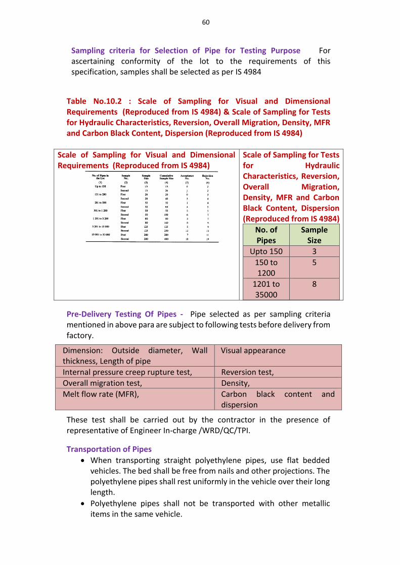
60
Sampling criteria for Selection of Pipe for Testing Purpose For ascertaining conformity of the lot to the requirements of this specification, samples shall be selected as per IS 4984
Table No.10.2 : Scale of Sampling for Visual and Dimensional Requirements (Reproduced from IS 4984) & Scale of Sampling for Tests for Hydraulic Characteristics, Reversion, Overall Migration, Density, MFR and Carbon Black Content, Dispersion (Reproduced from IS 4984)
Scale of Sampling for Visual and Dimensional Requirements (Reproduced from IS 4984)
Scale of Sampling for Tests for Hydraulic Characteristics, Reversion, Overall Migration, Density, MFR and Carbon Black Content, Dispersion (Reproduced from IS 4984)
No. of Pipes
Sample Size
Upto 150 3
150 to 1200
5
1201 to 35000
8
Pre-Delivery Testing Of Pipes - Pipe selected as per sampling criteria mentioned in above para are subject to following tests before delivery from factory.
Dimension: Outside diameter, Wall thickness, Length of pipe
Visual appearance
Internal pressure creep rupture test, Reversion test,
Overall migration test, Density,
Melt flow rate (MFR), Carbon black content and dispersion
These test shall be carried out by the contractor in the presence of representative of Engineer In-charge /WRD/QC/TPI.
Transportation of Pipes
When transporting straight polyethylene pipes, use flat bedded vehicles. The bed shall be free from nails and other projections. The polyethylene pipes shall rest uniformly in the vehicle over their long length.
Polyethylene pipes shall not be transported with other metallic items in the same vehicle.
61
Stacking Of Pipes at Site
PE pipes should not be subjected to rough handling during loading and unloading operations. Rollers shall be used to move, drag the pipes across any surface.
Pipe shall be stacked on reasonable flat surface, free from sharp object, stone or projection likely to deform or damage the pipes.
Laying of Pipes
The pipe line may be laid alongside of the trench and jointed there. There after the jointed pipeline shall be lowered into the trench carefully without causing undue bending. The pipeline shall be laid inside the trench with a slack of up to 2 m/100 m of pipe line.
Polyethylene pipe requires no special bed preparation for laying the pipe underground, except that there shall be no sharp objects around the pipe. However, while lying in rocky areas suitable sand bedding should be provided around the pipe and compacted. 100 mm compacted fine sand bedding under and around the pipe be provided in rocky areas.
Polyethylene pipes are non-metallic, so once buried, metal detector type locators are ineffective. To facilitate locating a buried PE pipe, metallic locating tapes or copper wires can be placed alongside the pipe. Locating tapes/wires are placed slightly above the crown of the pipe before the final back fill.
Jointing of Pipes - The Commonly used joints are as follows: a) Fusion welding
i. Butt fusion welding ii. Socket fusion welding
iii. Electro fusion welding b) Insert type joints; c) Compression fittings/push fit joints d) Flanged joints; and e) Spigot and socket joint
Field Testing of Pipeline System
Polyethylene pipelines shall be pressure tested at ambient temperature. After filling with water the pipeline shall be left to stabilize for a period of 1 hour.
The test pressure shall be 1.5 times the rated pressure of pipes or of the proposed maximum design pressure of the section.
If the pressure remains steady (within 5 percent of the target value) for 1½ h, leakage is not indicated.
10.2 Spirally Wound Steel Reinforced Pipes (SWSRP)
Introduction -The Spirally Wound Steel Reinforced Pipes (SWSRP) are structured wall pipes comprising of an HDPE inner smooth layer, spiral steel skeleton and outer corrugated profile of HDPE. The Spirally Wound Steel Reinforced Pipes (SWSRP) are structured wall pipes comprising of an HDPE inner smooth layer, spiral steel skeleton and outer corrugated profile of HDPE.
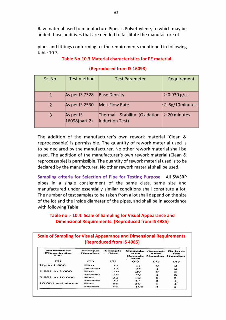
62
Raw material used to manufacture Pipes is Polyethylene, to which may be added those additives that are needed to facilitate the manufacture of pipes and fittings conforming to the requirements mentioned in following table 10.3.
Table No.10.3 Material characteristics for PE material.
(Reproduced from IS 16098)
Sr. No. Test method
Test Parameter Requirement
1 As per IS 7328 Base Density ≥ 0.930 g/cc
2 As per IS 2530 Melt Flow Rate ≤1.6g/10minutes.
3 As per IS 16098(part 2)
Thermal Stability (Oxidation Induction Test)
≥ 20 minutes
The addition of the manufacturer’s own rework material (Clean & reprocessable) is permissible. The quantity of rework material used is to be declared by the manufacturer. No other rework material shall be used. The addition of the manufacturer’s own rework material (Clean & reprocessable) is permissible. The quantity of rework material used is to be declared by the manufacturer. No other rework material shall be used.
Sampling criteria for Selection of Pipe for Testing Purpose All SWSRP pipes in a single consignment of the same class, same size and manufactured under essentially similar conditions shall constitute a lot. The number of test samples to be taken from a lot shall depend on the size of the lot and the inside diameter of the pipes, and shall be in accordance with following Table
Table no :- 10.4. Scale of Sampling for Visual Appearance and Dimensional Requirements. (Reproduced from IS 4985)
Scale of Sampling for Visual Appearance and Dimensional Requirements. (Reproduced from IS 4985)
63
Table No.10.5 : Scale of sampling for test other than visual and dimensional requirements ( reproduced from IS 16058)
No of pipes in lot
Sample size for ID ≤ 500mm
Sample size for ID ≥ 500mm
Upto 1000 2 1
1001 to 3000 3 2
More than 3000
4 3
Pre Delivery Testing of Pipes
Pipe selected as per sampling criteria mentioned in earlier para are subject to following tests before delivery from factory
1. Dimension: Length, Diameter of pipe & Socket dimensions or Fittings
2. Visual Appearance, 3. Colour of Finished Pipe, 4. Physical Characteristics 5. Mechanical Characteristics. Mechanical Characteristics.
These test shall be carried out by the contractor in the presence of representative of Engineer In-charge /WRD/QC/TPI. Table No.3 : Scale of sampling for test other than visual and dimensional
These pipes shall be selected at random from the lot and in order to ensure the randomness
Transportation of Pipes
When transporting pipes, flat bed vehicles should be used. When transporting pipes, flat bed vehicles should be used. The vehicle should be free from nails and other projections. Pipes should rest uniformly on the vehicle over the whole length.
Loading boom or fork lift should not be used directly on or inside the pipeobo olhould not be used directly on or insi
Stacking Of Pipes at Site
The area selected for stacking should be plain and care is to be taken to remove any pointed objects / stones f the The area selected for stacking should be plain and care is to be taken to remove any pointed objects / stones from the area.
Stacking shall done on a flat clear area as shown below
Stacking shall done on a flat clear area as shown be
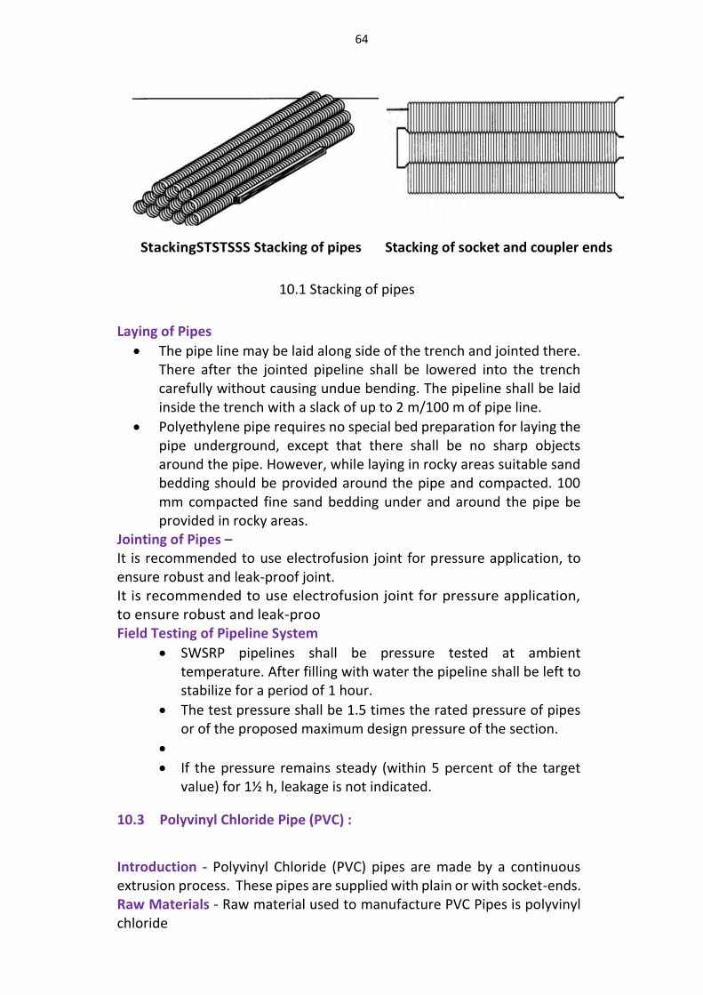
64
StackingSTSTSSS Stacking of pipes Stacking of socket and coupler ends
10.1 Stacking of pipes
Laying of Pipes
The pipe line may be laid along side of the trench and jointed there. There after the jointed pipeline shall be lowered into the trench carefully without causing undue bending. The pipeline shall be laid inside the trench with a slack of up to 2 m/100 m of pipe line.
Polyethylene pipe requires no special bed preparation for laying the pipe underground, except that there shall be no sharp objects around the pipe. However, while laying in rocky areas suitable sand bedding should be provided around the pipe and compacted. 100 mm compacted fine sand bedding under and around the pipe be provided in rocky areas.
Jointing of Pipes – It is recommended to use electrofusion joint for pressure application, to ensure robust and leak-proof joint. It is recommended to use electrofusion joint for pressure application, to ensure robust and leak-proo Field Testing of Pipeline System
SWSRP pipelines shall be pressure tested at ambient temperature. After filling with water the pipeline shall be left to stabilize for a period of 1 hour.
The test pressure shall be 1.5 times the rated pressure of pipes or of the proposed maximum design pressure of the section.
If the pressure remains steady (within 5 percent of the target value) for 1½ h, leakage is not indicated.
10.3 Polyvinyl Chloride Pipe (PVC) :
Introduction - Polyvinyl Chloride (PVC) pipes are made by a continuous extrusion process. These pipes are supplied with plain or with socket-ends. Raw Materials - Raw material used to manufacture PVC Pipes is polyvinyl chloride
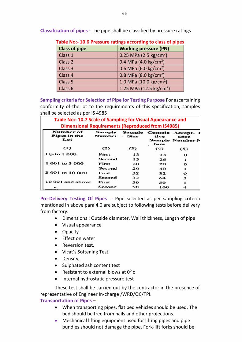
65
Classification of pipes - The pipe shall be classified by pressure ratings
Table No:- 10.6 Pressure ratings according to class of pipes
Class of pipe Working pressure (PN)
Class 1 0.25 MPa (2.5 kg/cm2)
Class 2 0.4 MPa (4.0 kg/cm2)
Class 3 0.6 MPa (6.0 kg/cm2)
Class 4 0.8 MPa (8.0 kg/cm2)
Class 5 1.0 MPa (10.0 kg/cm2)
Class 6 1.25 MPa (12.5 kg/cm2)
Sampling criteria for Selection of Pipe for Testing Purpose For ascertaining conformity of the lot to the requirements of this specification, samples shall be selected as per IS 4985
Table No:- 10.7 Scale of Sampling for Visual Appearance and Dimensional Requirements (Reproduced from IS4985)
Pre-Delivery Testing Of Pipes - Pipe selected as per sampling criteria mentioned in above para 4.0 are subject to following tests before delivery from factory.
Dimensions : Outside diameter, Wall thickness, Length of pipe
Visual appearance
Opacity
Effect on water
Reversion test,
Vicat’s Softening Test,
Density,
Sulphated ash content test
Resistant to external blows at 00 c
Internal hydrostatic pressure test
These test shall be carried out by the contractor in the presence of representative of Engineer In-charge /WRD/QC/TPI. Transportation of Pipes –
When transporting pipes, flat bed vehicles should be used. The bed should be free from nails and other projections.
Mechanical lifting equipment used for lifting pipes and pipe bundles should not damage the pipe. Fork-lift forks should be
66
flat and protected. Cranes should have spreader bars. No wire ropes, chains or hooks should be used.
Stacking Of Pipes at Site Pipes should be stacked on a surface flat and free from sharp objects,
stones or projections in order to avoid deformation or damage. Ends of pipes should be protected from abrasion and chipping. The pipes should be supported evenly over their whole length.
The bottom layer of the stack should be supported on wooden battens of unifrom size, at least 50 mm wide and placed not more that 2 m apart.
Stack height should not exceed 1.5 m in depots and stores or 1 m at construction sites.
Laying of Pipes
The trench bottom shall be constructed to provide a firm, stable and uniform support for the full length of the pipeline. There should be no sharp objects that may cause point loading.
A minimum bedding thickness of 100 to 150 mm under the pipe shall be provided by watering and compaction
The pipes shall be preferably laid with the spigots entered into the sockets in the same direction as the intended flow of water.
To sustain thrust caused by internal pressure, concrete anchor blocks should be provided at all changes of direction.
Metal marker tape can be laid into the final backfill to enable electronic location of the pipe line.
Jointing of Pipes - Commonly used joints are as follows a) Solvent welded joints, b) Integral elastomeric sealing ring joints, c) Mechanical compression joints, d) Flanged joints, e) Screwed or threaded joints, f) Union coupled joints
Field Testing of Pipeline System
All pipelines should be tested before being brought into service. The test should be a hydrostatic test performed by filling the pipeline with water and raising the pressure to the selected test pressure and maintaining this for a sufficient period to allow for absorption of water by the pipe material.
The test should confirm to following conditions a) be applied for at least 1 h, but not more than 24 h; and b) not exceed 1.5 times the maximum rated pressure of the
lowest rated component.
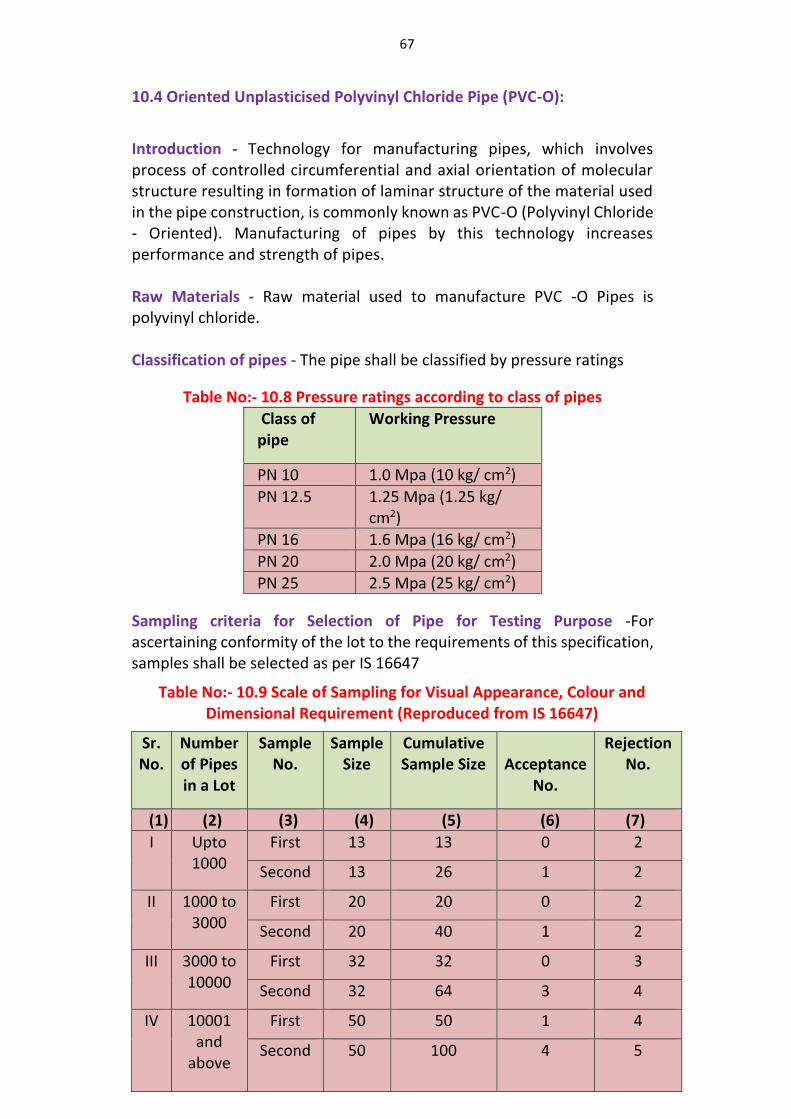
67
10.4 Oriented Unplasticised Polyvinyl Chloride Pipe (PVC-O):
Introduction - Technology for manufacturing pipes, which involves process of controlled circumferential and axial orientation of molecular structure resulting in formation of laminar structure of the material used in the pipe construction, is commonly known as PVC-O (Polyvinyl Chloride - Oriented). Manufacturing of pipes by this technology increases performance and strength of pipes. Raw Materials - Raw material used to manufacture PVC -O Pipes is polyvinyl chloride. Classification of pipes - The pipe shall be classified by pressure ratings
Table No:- 10.8 Pressure ratings according to class of pipes
Class of pipe
Working Pressure
PN 10 1.0 Mpa (10 kg/ cm2)
PN 12.5 1.25 Mpa (1.25 kg/ cm2)
PN 16 1.6 Mpa (16 kg/ cm2)
PN 20 2.0 Mpa (20 kg/ cm2)
PN 25 2.5 Mpa (25 kg/ cm2)
Sampling criteria for Selection of Pipe for Testing Purpose -For ascertaining conformity of the lot to the requirements of this specification, samples shall be selected as per IS 16647
Table No:- 10.9 Scale of Sampling for Visual Appearance, Colour and Dimensional Requirement (Reproduced from IS 16647)
Sr. No.
Number of Pipes in a Lot
Sample No.
Sample Size
Cumulative Sample Size
Acceptance
No.
Rejection No.
(1) (2) (3) (4) (5) (6) (7)
I Upto 1000
First 13 13 0 2
Second 13 26 1 2
II 1000 to 3000
First 20 20 0 2
Second 20 40 1 2
III 3000 to 10000
First 32 32 0 3
Second 32 64 3 4
IV 10001 and
above
First 50 50 1 4
Second 50 100 4 5
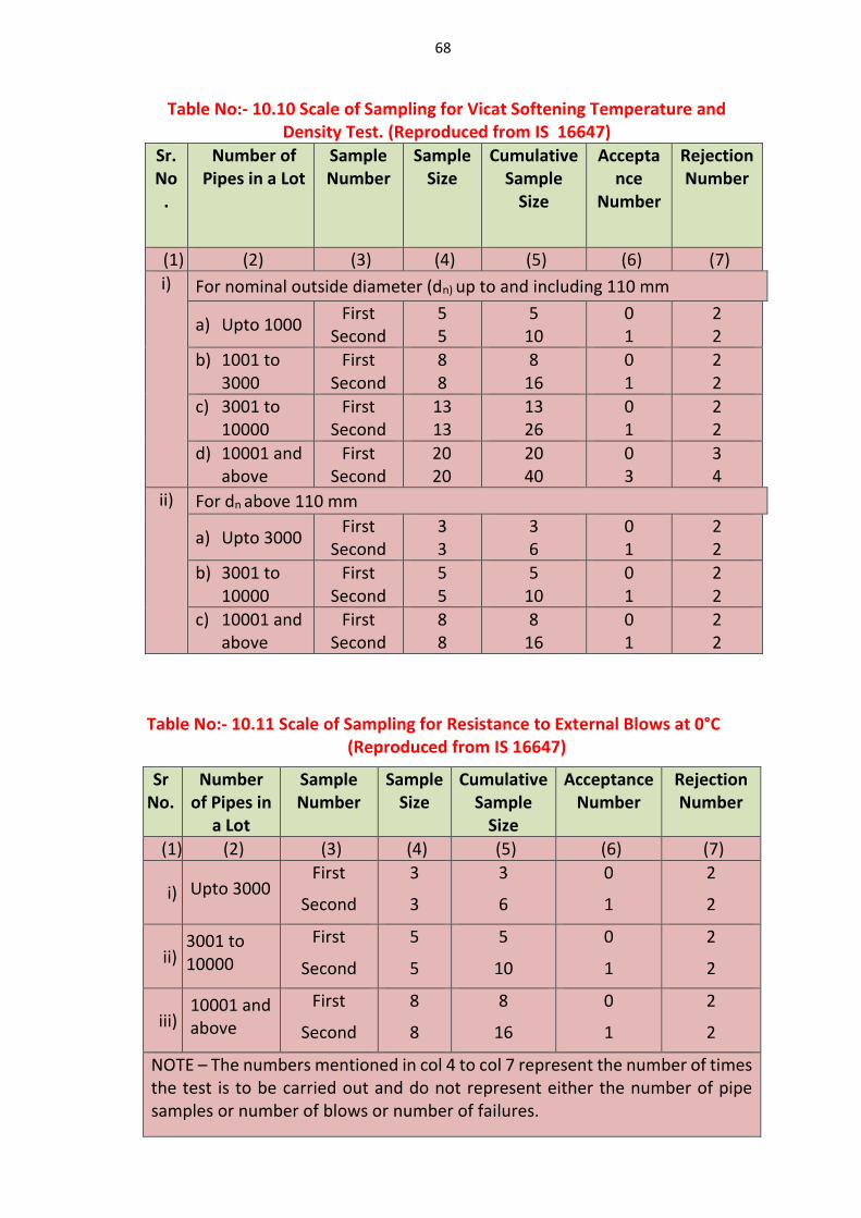
68
Table No:- 10.10 Scale of Sampling for Vicat Softening Temperature and Density Test. (Reproduced from IS 16647)
Sr. No
.
Number of Pipes in a Lot
Sample Number
Sample Size
Cumulative Sample
Size
Acceptance
Number
Rejection Number
(1) (2) (3) (4) (5) (6) (7)
i) For nominal outside diameter (dn) up to and including 110 mm
a) Upto 1000 First
Second 5 5
5 10
0 1
2 2
b) 1001 to 3000
First Second
8 8
8 16
0 1
2 2
c) 3001 to 10000
First Second
13 13
13 26
0 1
2 2
d) 10001 and above
First Second
20 20
20 40
0 3
3 4
ii) For dn above 110 mm
a) Upto 3000 First
Second 3 3
3 6
0 1
2 2
b) 3001 to 10000
First Second
5 5
5 10
0 1
2 2
c) 10001 and above
First Second
8 8
8 16
0 1
2 2
Table No:- 10.11 Scale of Sampling for Resistance to External Blows at 0°C (Reproduced from IS 16647)
Sr No.
Number of Pipes in
a Lot
Sample Number
Sample Size
Cumulative Sample
Size
Acceptance Number
Rejection Number
(1) (2) (3) (4) (5) (6) (7)
i) Upto 3000 First
Second
3
3
3
6
0
1
2
2
ii) 3001 to 10000
First
Second
5
5
5
10
0
1
2
2
iii) 10001 and above
First
Second
8
8
8
16
0
1
2
2
NOTE – The numbers mentioned in col 4 to col 7 represent the number of times the test is to be carried out and do not represent either the number of pipe samples or number of blows or number of failures.
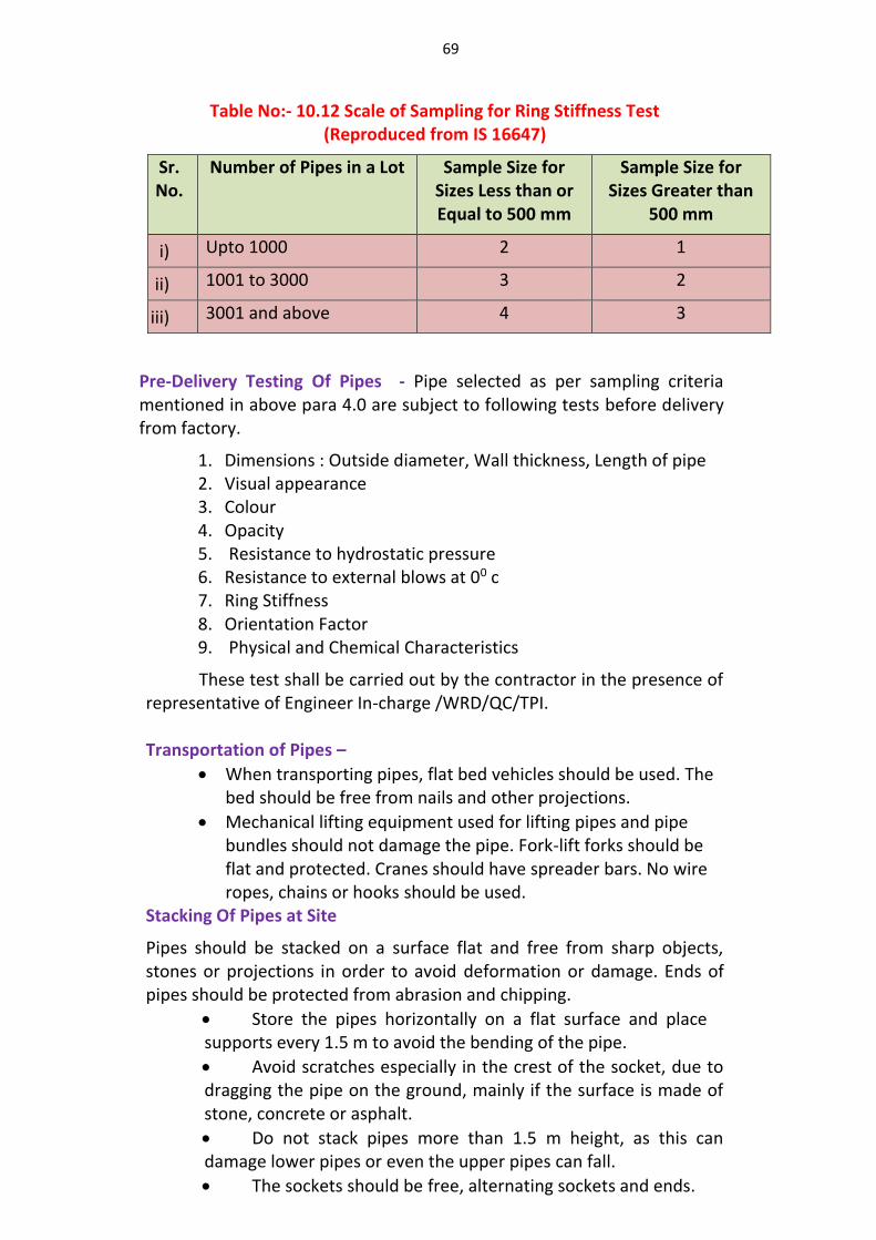
69
Table No:- 10.12 Scale of Sampling for Ring Stiffness Test (Reproduced from IS 16647)
Sr. No.
Number of Pipes in a Lot Sample Size for Sizes Less than or Equal to 500 mm
Sample Size for Sizes Greater than
500 mm
i) Upto 1000 2 1
ii) 1001 to 3000 3 2
iii) 3001 and above 4 3
Pre-Delivery Testing Of Pipes - Pipe selected as per sampling criteria mentioned in above para 4.0 are subject to following tests before delivery from factory.
1. Dimensions : Outside diameter, Wall thickness, Length of pipe 2. Visual appearance 3. Colour 4. Opacity 5. Resistance to hydrostatic pressure 6. Resistance to external blows at 00 c 7. Ring Stiffness 8. Orientation Factor 9. Physical and Chemical Characteristics
These test shall be carried out by the contractor in the presence of representative of Engineer In-charge /WRD/QC/TPI. Transportation of Pipes –
When transporting pipes, flat bed vehicles should be used. The bed should be free from nails and other projections.
Mechanical lifting equipment used for lifting pipes and pipe bundles should not damage the pipe. Fork-lift forks should be flat and protected. Cranes should have spreader bars. No wire ropes, chains or hooks should be used.
Stacking Of Pipes at Site
Pipes should be stacked on a surface flat and free from sharp objects, stones or projections in order to avoid deformation or damage. Ends of pipes should be protected from abrasion and chipping.
Store the pipes horizontally on a flat surface and place supports every 1.5 m to avoid the bending of the pipe.
Avoid scratches especially in the crest of the socket, due to dragging the pipe on the ground, mainly if the surface is made of stone, concrete or asphalt.
Do not stack pipes more than 1.5 m height, as this can damage lower pipes or even the upper pipes can fall.
The sockets should be free, alternating sockets and ends.
70
In case of prolonged sun exposure, protect pallets with an opaque material. White colour is preferable because it avoids the over heating of pipes
Laying of Pipes
The trench bottom shall be constructed to provide a firm, stable and uniform support for the full length of the pipeline. There should be no sharp objects that may cause point loading.
A minimum bedding thickness of 100 to 150 mm under the pipe shall be provided by watering and compaction
The pipes shall be preferably laid with the spigots entered into the sockets in the same direction as the intended flow of water.
To sustain thrust caused by internal pressure, concrete anchor blocks should be provided at all changes of direction.
Metal marker tape can be laid into the final backfill to enable electronic location of the pipe line.
Jointing of Pipes - Commonly used joints are as follows
Lubricate the chamfer of the spigot and the seal with joint lubricant.
Line up the pipe as much as possible horizontal and vertically.
Insert only the chamfer edge of the socket, just to support the pipe but leaving the socket lip free.
In case of pipes with nominal daimeter ≤ 250 mm, a firm and dry push should be given to seize the momentum produced by the free movement in the lip of the socket and introduce it until the mark is hidden into the socket.
When installing pipes with diameters > 250 mm, one should use mechanical means to introduce the pipe using materials such as woods, hoists, tackles or slings.
Field Testing of Pipeline System
All pipelines should be tested before being brought into service. The test should be a hydrostatic test performed by filling the pipeline with water and raising the pressure to the selected test pressure and maintaining this for a sufficient period to allow for absorption of water by the pipe material.
The test should confirm to following conditions c) be applied for at least 1 h, but not more than 24 h; and d) not exceed 1.5 times the maximum rated pressure of the
lowest rated component.
10.5 Glass Fiber Reinforced Plastic Pipe (GRP) :
Introduction - Glass fibre reinforced Plastic (GRP) pipe is a machine made tubular pipe containing glass fibre reinforcements embedded in or surrounded by cured thermosetting resin.
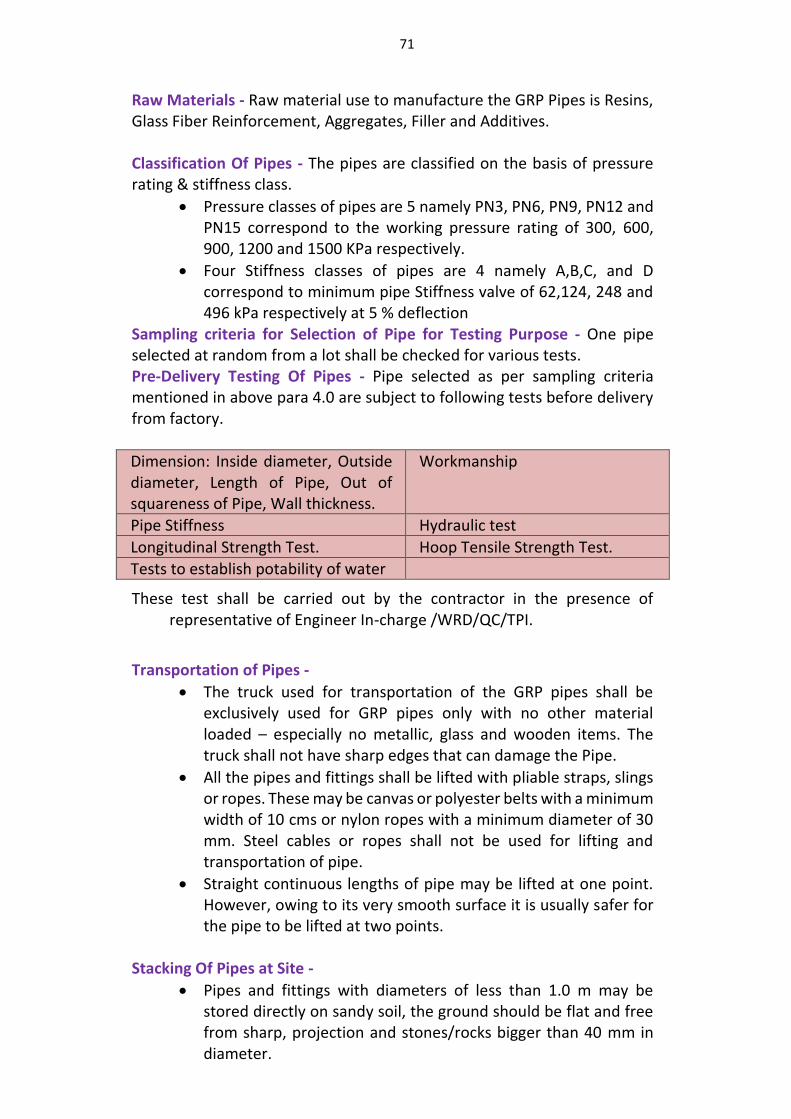
71
Raw Materials - Raw material use to manufacture the GRP Pipes is Resins, Glass Fiber Reinforcement, Aggregates, Filler and Additives. Classification Of Pipes - The pipes are classified on the basis of pressure rating & stiffness class.
Pressure classes of pipes are 5 namely PN3, PN6, PN9, PN12 and PN15 correspond to the working pressure rating of 300, 600, 900, 1200 and 1500 KPa respectively.
Four Stiffness classes of pipes are 4 namely A,B,C, and D correspond to minimum pipe Stiffness valve of 62,124, 248 and 496 kPa respectively at 5 % deflection
Sampling criteria for Selection of Pipe for Testing Purpose - One pipe selected at random from a lot shall be checked for various tests. Pre-Delivery Testing Of Pipes - Pipe selected as per sampling criteria mentioned in above para 4.0 are subject to following tests before delivery from factory.
Dimension: Inside diameter, Outside diameter, Length of Pipe, Out of squareness of Pipe, Wall thickness.
Workmanship
Pipe Stiffness Hydraulic test
Longitudinal Strength Test. Hoop Tensile Strength Test.
Tests to establish potability of water
These test shall be carried out by the contractor in the presence of representative of Engineer In-charge /WRD/QC/TPI.
Transportation of Pipes -
The truck used for transportation of the GRP pipes shall be exclusively used for GRP pipes only with no other material loaded – especially no metallic, glass and wooden items. The truck shall not have sharp edges that can damage the Pipe.
All the pipes and fittings shall be lifted with pliable straps, slings or ropes. These may be canvas or polyester belts with a minimum width of 10 cms or nylon ropes with a minimum diameter of 30 mm. Steel cables or ropes shall not be used for lifting and transportation of pipe.
Straight continuous lengths of pipe may be lifted at one point. However, owing to its very smooth surface it is usually safer for the pipe to be lifted at two points.
Stacking Of Pipes at Site -
Pipes and fittings with diameters of less than 1.0 m may be stored directly on sandy soil, the ground should be flat and free from sharp, projection and stones/rocks bigger than 40 mm in diameter.
72
Pipes with diameters greater than 1.0 m may be stored on their delivery cradles at a maximum distance of 6 m c/c
Laying of Pipes -
For a coupling type of joint, two rubber ring gaskets are first fixed into the groove inside the coupling and then the coupling is to be fixed at the coupling area of the pipe and pipe is to be lowered in the trench.
For socket and spigot type of joint, pass the rubber ring under the pipe until it settles into the groove, then pull it forcibly upwards and follow the ring with the hands so that three quarters of it is positioned in the groove, then lift the ring above the upper generating line of the pipe forcibly and then release it so that it falls into the groove thus being freed of any twists.
RCC thrust blocks should be provided at bends and at places of reductions in cross section to take care of thrust.
The pipe should be uniformly and continuously supported throughout its whole length with firm stable bedding material. The bedding material should be placed so as to give complete contact between the bottom of the trench and pipe. The bedding material should be watered and compacted.
Jointing Of Pipes- Commonly used joints are as follows
Unrestrained Pipe Joint a. Spigot and Socket Joint b. Double Socket Coupling Joint
Restrained Pipe Joint
Butt Joint
Flanged joint Field Testing Of Pipeline System
All pipelines should be tested before being brought into service. The test should be a hydrostatic test performed by filling the pipeline with water and raising the pressure to the selected test pressure and maintaining this for a sufficient period to allow for absorption of water by the pipe material.
The test pressure shall be 1.5 times the rated pressure for a given class of pipes or fittings. The test pressure shall be maintained for a period of 24 hours.
10.6 Prestressed Concrete Non-cylinder Pipe (PSC) :
Introduction - Prestressed Concrete Non-Cylinder Pipe is suitably compacted concrete core longitudinally prestressed with pretensioned high tensile steel wire embedded in the concrete, circumferentially prestressed and coated with cement mortar or concrete.
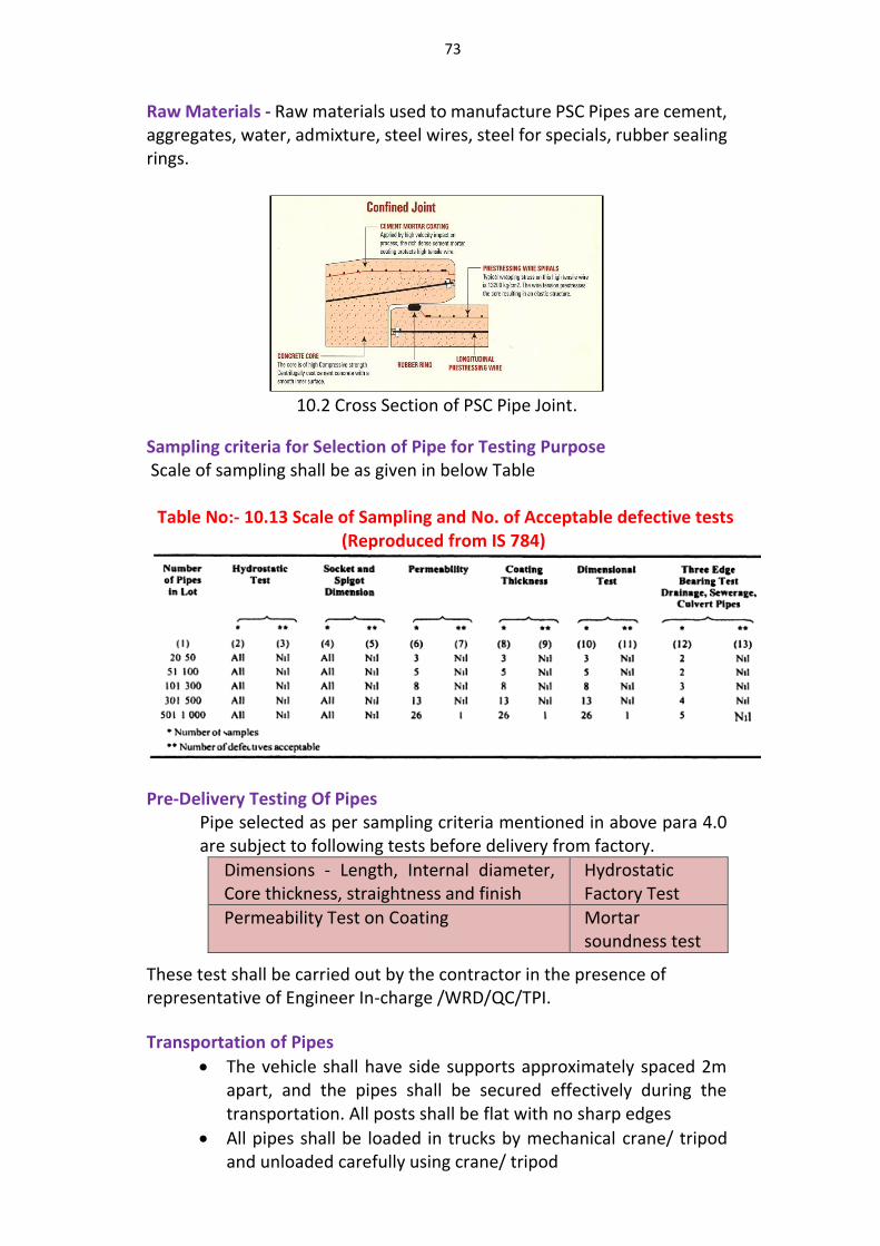
73
Raw Materials - Raw materials used to manufacture PSC Pipes are cement, aggregates, water, admixture, steel wires, steel for specials, rubber sealing rings.
10.2 Cross Section of PSC Pipe Joint.
Sampling criteria for Selection of Pipe for Testing Purpose Scale of sampling shall be as given in below Table
Table No:- 10.13 Scale of Sampling and No. of Acceptable defective tests
(Reproduced from IS 784)
Pre-Delivery Testing Of Pipes
Pipe selected as per sampling criteria mentioned in above para 4.0 are subject to following tests before delivery from factory.
Dimensions - Length, Internal diameter, Core thickness, straightness and finish
Hydrostatic Factory Test
Permeability Test on Coating Mortar soundness test
These test shall be carried out by the contractor in the presence of representative of Engineer In-charge /WRD/QC/TPI.
Transportation of Pipes
The vehicle shall have side supports approximately spaced 2m apart, and the pipes shall be secured effectively during the transportation. All posts shall be flat with no sharp edges
All pipes shall be loaded in trucks by mechanical crane/ tripod and unloaded carefully using crane/ tripod
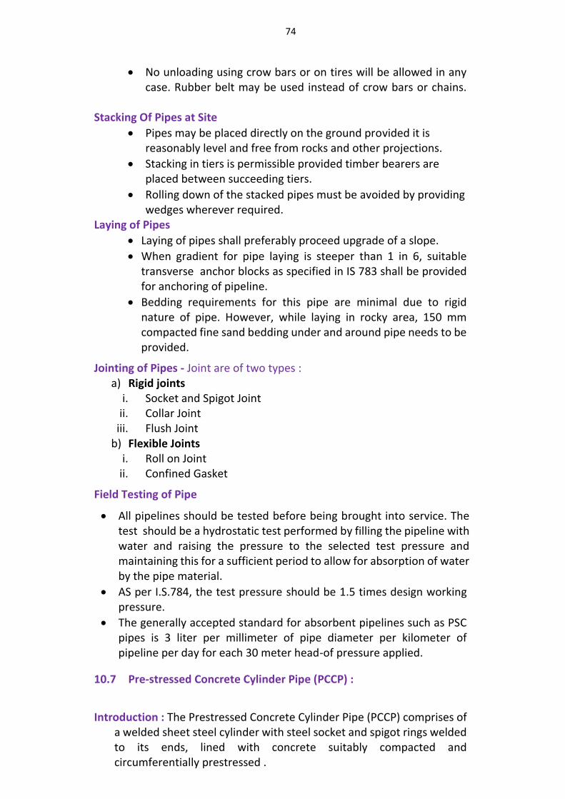
74
No unloading using crow bars or on tires will be allowed in any case. Rubber belt may be used instead of crow bars or chains.
Stacking Of Pipes at Site
Pipes may be placed directly on the ground provided it is reasonably level and free from rocks and other projections.
Stacking in tiers is permissible provided timber bearers are placed between succeeding tiers.
Rolling down of the stacked pipes must be avoided by providing wedges wherever required.
Laying of Pipes
Laying of pipes shall preferably proceed upgrade of a slope.
When gradient for pipe laying is steeper than 1 in 6, suitable transverse anchor blocks as specified in IS 783 shall be provided for anchoring of pipeline.
Bedding requirements for this pipe are minimal due to rigid nature of pipe. However, while laying in rocky area, 150 mm compacted fine sand bedding under and around pipe needs to be provided.
Jointing of Pipes - Joint are of two types : a) Rigid joints
i. Socket and Spigot Joint ii. Collar Joint
iii. Flush Joint b) Flexible Joints
i. Roll on Joint ii. Confined Gasket
Field Testing of Pipe
All pipelines should be tested before being brought into service. The test should be a hydrostatic test performed by filling the pipeline with water and raising the pressure to the selected test pressure and maintaining this for a sufficient period to allow for absorption of water by the pipe material.
AS per I.S.784, the test pressure should be 1.5 times design working pressure.
The generally accepted standard for absorbent pipelines such as PSC pipes is 3 liter per millimeter of pipe diameter per kilometer of pipeline per day for each 30 meter head-of pressure applied.
10.7 Pre-stressed Concrete Cylinder Pipe (PCCP) :
Introduction : The Prestressed Concrete Cylinder Pipe (PCCP) comprises of a welded sheet steel cylinder with steel socket and spigot rings welded to its ends, lined with concrete suitably compacted and circumferentially prestressed .
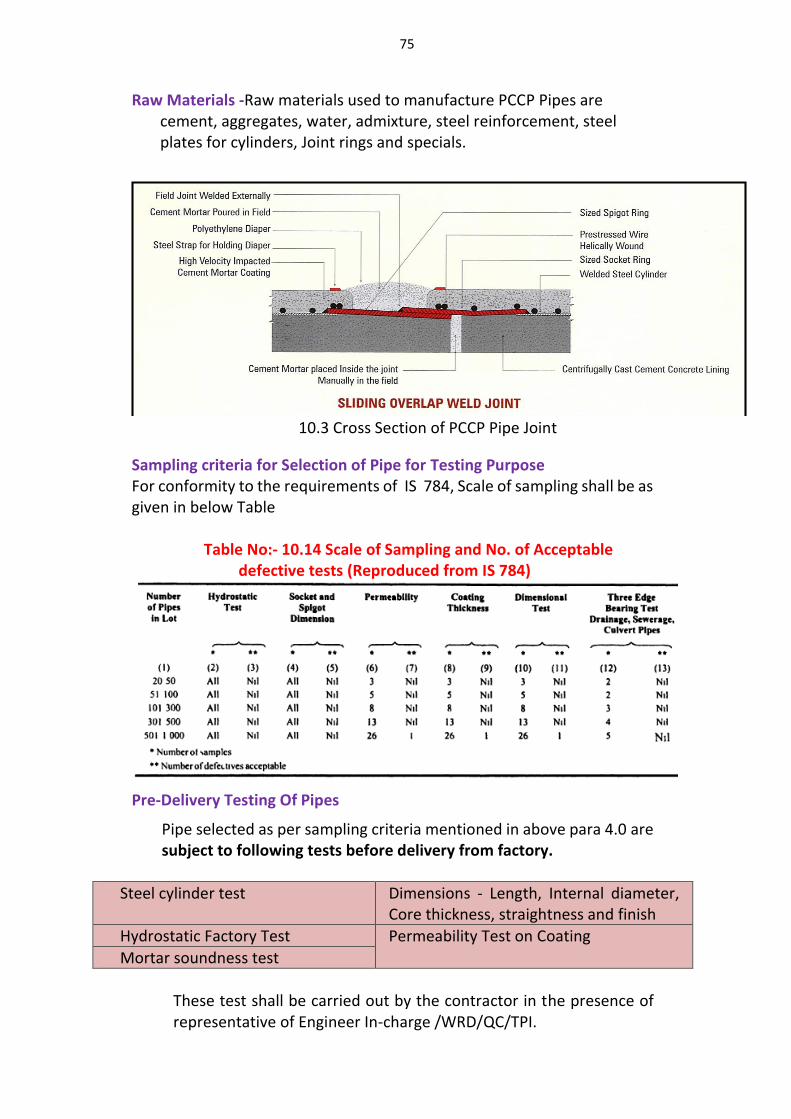
75
Raw Materials -Raw materials used to manufacture PCCP Pipes are cement, aggregates, water, admixture, steel reinforcement, steel plates for cylinders, Joint rings and specials.
10.3 Cross Section of PCCP Pipe Joint
Sampling criteria for Selection of Pipe for Testing Purpose For conformity to the requirements of IS 784, Scale of sampling shall be as given in below Table
Table No:- 10.14 Scale of Sampling and No. of Acceptable
defective tests (Reproduced from IS 784)
Pre-Delivery Testing Of Pipes
Pipe selected as per sampling criteria mentioned in above para 4.0 are subject to following tests before delivery from factory.
Steel cylinder test Dimensions - Length, Internal diameter, Core thickness, straightness and finish
Hydrostatic Factory Test Permeability Test on Coating
Mortar soundness test
These test shall be carried out by the contractor in the presence of representative of Engineer In-charge /WRD/QC/TPI.
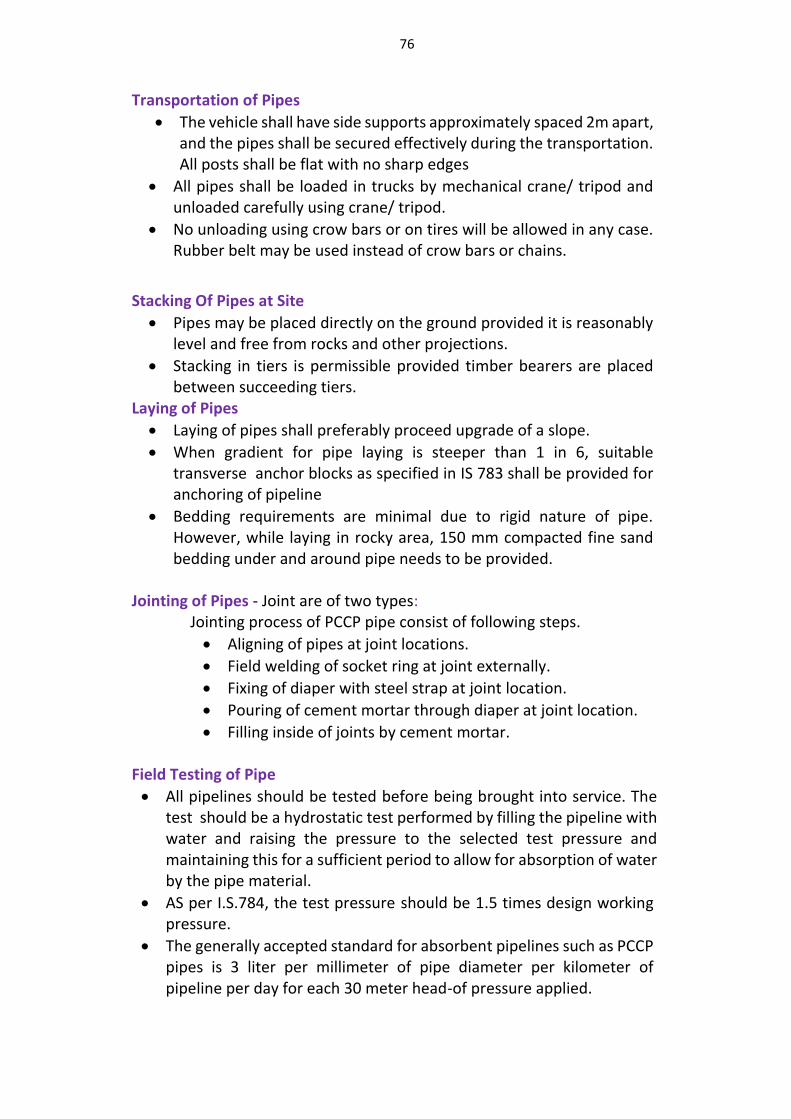
76
Transportation of Pipes
The vehicle shall have side supports approximately spaced 2m apart, and the pipes shall be secured effectively during the transportation. All posts shall be flat with no sharp edges
All pipes shall be loaded in trucks by mechanical crane/ tripod and unloaded carefully using crane/ tripod.
No unloading using crow bars or on tires will be allowed in any case. Rubber belt may be used instead of crow bars or chains.
Stacking Of Pipes at Site
Pipes may be placed directly on the ground provided it is reasonably level and free from rocks and other projections.
Stacking in tiers is permissible provided timber bearers are placed between succeeding tiers.
Laying of Pipes
Laying of pipes shall preferably proceed upgrade of a slope.
When gradient for pipe laying is steeper than 1 in 6, suitable transverse anchor blocks as specified in IS 783 shall be provided for anchoring of pipeline
Bedding requirements are minimal due to rigid nature of pipe. However, while laying in rocky area, 150 mm compacted fine sand bedding under and around pipe needs to be provided.
Jointing of Pipes - Joint are of two types: Jointing process of PCCP pipe consist of following steps.
Aligning of pipes at joint locations.
Field welding of socket ring at joint externally.
Fixing of diaper with steel strap at joint location.
Pouring of cement mortar through diaper at joint location.
Filling inside of joints by cement mortar. Field Testing of Pipe
All pipelines should be tested before being brought into service. The test should be a hydrostatic test performed by filling the pipeline with water and raising the pressure to the selected test pressure and maintaining this for a sufficient period to allow for absorption of water by the pipe material.
AS per I.S.784, the test pressure should be 1.5 times design working pressure.
The generally accepted standard for absorbent pipelines such as PCCP pipes is 3 liter per millimeter of pipe diameter per kilometer of pipeline per day for each 30 meter head-of pressure applied.
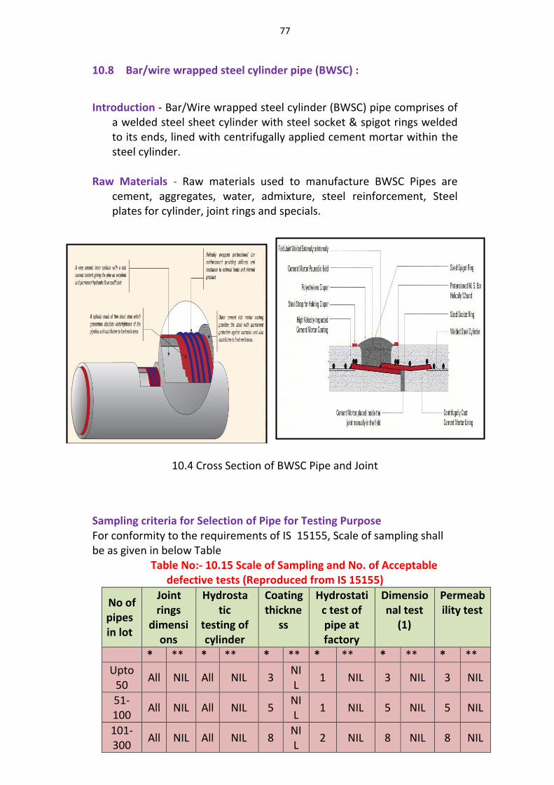
77
10.8 Bar/wire wrapped steel cylinder pipe (BWSC) :
Introduction - Bar/Wire wrapped steel cylinder (BWSC) pipe comprises of a welded steel sheet cylinder with steel socket & spigot rings welded to its ends, lined with centrifugally applied cement mortar within the steel cylinder.
Raw Materials - Raw materials used to manufacture BWSC Pipes are
cement, aggregates, water, admixture, steel reinforcement, Steel plates for cylinder, joint rings and specials.
10.4 Cross Section of BWSC Pipe and Joint
Sampling criteria for Selection of Pipe for Testing Purpose For conformity to the requirements of IS 15155, Scale of sampling shall be as given in below Table
Table No:- 10.15 Scale of Sampling and No. of Acceptable defective tests (Reproduced from IS 15155)
No of pipes in lot
Joint rings
dimensions
Hydrostatic
testing of cylinder
Coating thickne
ss
Hydrostatic test of pipe at factory
Dimensional test
(1)
Permeability test
* ** * ** * ** * ** * ** * **
Upto 50
All NIL All NIL 3 NIL
1 NIL 3 NIL 3 NIL
51-100
All NIL All NIL 5 NIL
1 NIL 5 NIL 5 NIL
101-300
All NIL All NIL 8 NIL
2 NIL 8 NIL 8 NIL
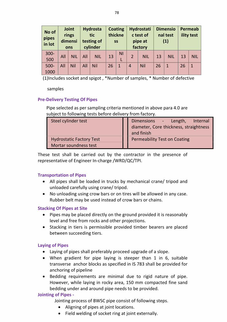
78
No of pipes in lot
Joint rings
dimensions
Hydrostatic
testing of cylinder
Coating thickne
ss
Hydrostatic test of pipe at factory
Dimensional test
(1)
Permeability test
300-500
All NIL All NIL 13 NIL
2 NIL 13 NIL 13 NIL
500-1000
All Nil All Nil 26 1 4 Nil 26 1 26 1
(1)Includes socket and spigot , *Number of samples, * Number of defective
samples
Pre-Delivery Testing Of Pipes
Pipe selected as per sampling criteria mentioned in above para 4.0 are subject to following tests before delivery from factory.
Steel cylinder test Dimensions - Length, Internal diameter, Core thickness, straightness and finish
Hydrostatic Factory Test Permeability Test on Coating Mortar soundness test
These test shall be carried out by the contractor in the presence of representative of Engineer In-charge /WRD/QC/TPI.
Transportation of Pipes
All pipes shall be loaded in trucks by mechanical crane/ tripod and unloaded carefully using crane/ tripod.
No unloading using crow bars or on tires will be allowed in any case. Rubber belt may be used instead of crow bars or chains.
Stacking Of Pipes at Site
Pipes may be placed directly on the ground provided it is reasonably level and free from rocks and other projections.
Stacking in tiers is permissible provided timber bearers are placed between succeeding tiers.
Laying of Pipes
Laying of pipes shall preferably proceed upgrade of a slope.
When gradient for pipe laying is steeper than 1 in 6, suitable transverse anchor blocks as specified in IS 783 shall be provided for anchoring of pipeline
Bedding requirements are minimal due to rigid nature of pipe. However, while laying in rocky area, 150 mm compacted fine sand bedding under and around pipe needs to be provided.
Jointing of Pipes - Jointing process of BWSC pipe consist of following steps.
Aligning of pipes at joint locations.
Field welding of socket ring at joint externally.
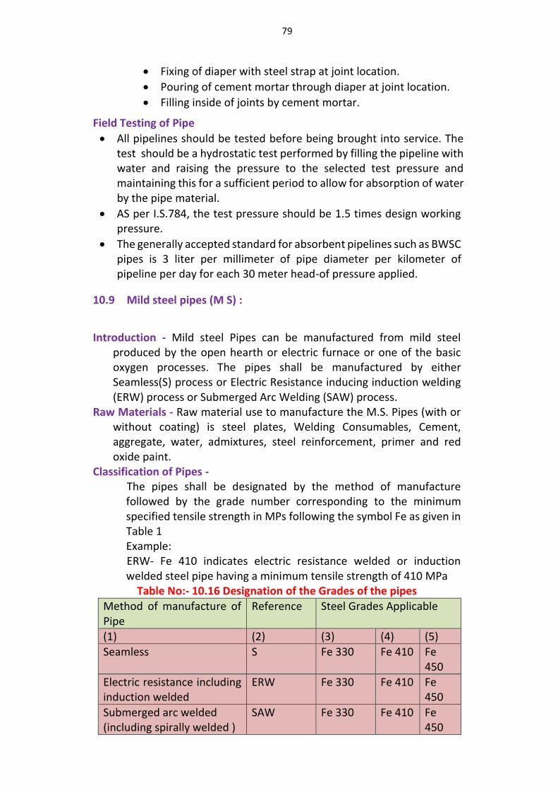
79
Fixing of diaper with steel strap at joint location.
Pouring of cement mortar through diaper at joint location.
Filling inside of joints by cement mortar.
Field Testing of Pipe
All pipelines should be tested before being brought into service. The test should be a hydrostatic test performed by filling the pipeline with water and raising the pressure to the selected test pressure and maintaining this for a sufficient period to allow for absorption of water by the pipe material.
AS per I.S.784, the test pressure should be 1.5 times design working pressure.
The generally accepted standard for absorbent pipelines such as BWSC pipes is 3 liter per millimeter of pipe diameter per kilometer of pipeline per day for each 30 meter head-of pressure applied.
10.9 Mild steel pipes (M S) :
Introduction - Mild steel Pipes can be manufactured from mild steel produced by the open hearth or electric furnace or one of the basic oxygen processes. The pipes shall be manufactured by either Seamless(S) process or Electric Resistance inducing induction welding (ERW) process or Submerged Arc Welding (SAW) process.
Raw Materials - Raw material use to manufacture the M.S. Pipes (with or without coating) is steel plates, Welding Consumables, Cement, aggregate, water, admixtures, steel reinforcement, primer and red oxide paint.
Classification of Pipes - The pipes shall be designated by the method of manufacture followed by the grade number corresponding to the minimum specified tensile strength in MPs following the symbol Fe as given in Table 1 Example: ERW- Fe 410 indicates electric resistance welded or induction welded steel pipe having a minimum tensile strength of 410 MPa
Table No:- 10.16 Designation of the Grades of the pipes
Method of manufacture of Pipe
Reference Steel Grades Applicable
(1) (2) (3) (4) (5)
Seamless S Fe 330 Fe 410 Fe 450
Electric resistance including induction welded
ERW Fe 330 Fe 410 Fe 450
Submerged arc welded (including spirally welded )
SAW Fe 330 Fe 410 Fe 450
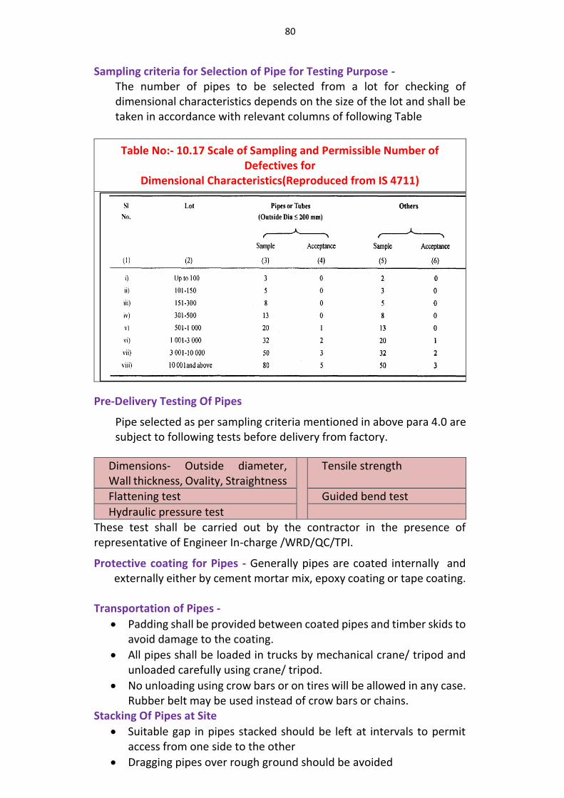
80
Sampling criteria for Selection of Pipe for Testing Purpose - The number of pipes to be selected from a lot for checking of dimensional characteristics depends on the size of the lot and shall be taken in accordance with relevant columns of following Table
Table No:- 10.17 Scale of Sampling and Permissible Number of Defectives for
Dimensional Characteristics(Reproduced from IS 4711)
Pre-Delivery Testing Of Pipes
Pipe selected as per sampling criteria mentioned in above para 4.0 are subject to following tests before delivery from factory.
Dimensions- Outside diameter, Wall thickness, Ovality, Straightness
Tensile strength
Flattening test Guided bend test
Hydraulic pressure test
These test shall be carried out by the contractor in the presence of representative of Engineer In-charge /WRD/QC/TPI.
Protective coating for Pipes - Generally pipes are coated internally and externally either by cement mortar mix, epoxy coating or tape coating.
Transportation of Pipes -
Padding shall be provided between coated pipes and timber skids to avoid damage to the coating.
All pipes shall be loaded in trucks by mechanical crane/ tripod and unloaded carefully using crane/ tripod.
No unloading using crow bars or on tires will be allowed in any case. Rubber belt may be used instead of crow bars or chains.
Stacking Of Pipes at Site
Suitable gap in pipes stacked should be left at intervals to permit access from one side to the other
Dragging pipes over rough ground should be avoided
81
Pipe shall be stacked on reasonable flat surface, free from sharp object, stone or projection likely to deform or damage the pipes
Laying of Pipes
Before the pipe is lowered, the trench shall be carefully examined to determine that even bedding is provided for the pipeline and that the pipe may be lowered into it without damaging the coating. While laying in rocky areas, 150 mm compacted fine sand bedding under and around pipe needs to be provided.
In case of coated pipes, extra care shall be taken to preserve the coating while lowering. Slings may be removed progressively without the necessity of digging under the pipe.
Care shall be taken to see that the longitudinal joints of the consecutive pipes are staggered by at least 30o and should be kept in upper third of the pipeline, if there are two longitudinal joints they should be on the sides.
The pipe faces shall first be tack-welded alternately at one or more diametrically opposite pairs of points. After completing tack-welding, full welding shall be carried out in suitable runs following a sequence of welding portions of segments diametrically opposite.
Jointing of Pipes: Jointing of Pipes is done by butt wielding Field Testing of Pipe
All pipelines should be tested before being brought into service. The test should be a hydrostatic test performed by filling the pipeline with water and raising the pressure to the selected test pressure and maintaining this for a sufficient period to allow for absorption of water by the pipe material.
The field test pressure should not be less than the greatest of the following a) 1 times the maximum sustained operating pressure b) 1 times the maximum pipeline static pressure, and c) Sum of maximum static pressure and surge pressure subjected to
the test pressure.
Where the field test pressure is less than two – thirds the test pressure, the period of test should be at least 24 hours.
If a drop in pressure occurs, the quantity of water added in order to re-establish the test pressure should be carefully measured. This should not exceed 0.1 lit per mm of pipe dia per km of pipeline per day for each 30 m head of pressure applied.
10.10 Ductile iron pipes (DI) :
Introduction - Ductile iron (DI) pipes are manufactured from ductile iron. Ductile iron is a type of iron in which graphite is present primarily in spherical or nodular form.
Raw Materials - Raw material used in manufacturing of pipes (with or without coating) is ductile iron, cement, sand, water, zinc, bitumen, polyethylene and rubber gasket.
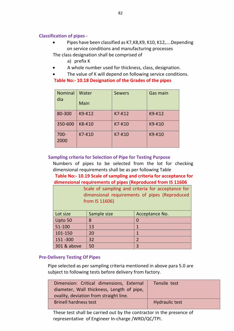
82
Classification of pipes -
Pipes have been classified as K7,K8,K9, K10, K12,….Depending on service conditions and manufacturing processes
The class designation shall be comprised of a) prefix K
A whole number used for thickness, class, designation.
The value of K will depend on following service conditions. Table No:- 10.18 Designation of the Grades of the pipes
Nominal dia
Water
Main
Sewers Gas main
80-300 K9-K12 K7-K12 K9-K12
350-600 K8-K10 K7-K10 K9-K10
700-2000
K7-K10 K7-K10 K9-K10
Sampling criteria for Selection of Pipe for Testing Purpose
Numbers of pipes to be selected from the lot for checking dimensional requirements shall be as per following Table
Table No:- 10.19 Scale of sampling and criteria for acceptance for dimensional requirements of pipes (Reproduced from IS 11606
Scale of sampling and criteria for acceptance for dimensional requirements of pipes (Reproduced from IS 11606)
Lot size Sample size Acceptance No.
Upto 50 8 0
51-100 13 1
101-150 20 1
151 -300 32 2
301 & above 50 3
Pre-Delivery Testing Of Pipes
Pipe selected as per sampling criteria mentioned in above para 5.0 are subject to following tests before delivery from factory.
Dimension: Critical dimensions, External diameter, Wall thickness, Length of pipe, ovality, deviation from straight line.
Tensile test
Brinell hardness test Hydraulic test
These test shall be carried out by the contractor in the presence of representative of Engineer In-charge /WRD/QC/TPI.
83
Coating on pipes- DI pipes shall normally be coated internally and externally either by zinc coating, bituminous coating or cement mortar lining.
Transportation of Pipes -
DI pipes are less susceptible to cracking or breaking or impact but precautions should be taken to prevent damage to the protective coating
The pipes should be loaded on vehicles in pyramid or straight sided formation. The use of straight sided loading is advantageous for utilizing full capacity of the vehicle.
Cranes should be preferred for off-loading. However, for pipes up to 400 mm nominal bore, skid timbers and ropes may be used.
Stacking of pipes at site -
The first layer of pipes should be laid on a firm foundation consisting of solid timbers set level on the ground. Subsequent layers should be placed according to the method of stacking adopted. The height of any stack should not exceed 2 m. Stacking of pipes can be either square or parallel or nested .
Laying of Pipes -
For smaller sizes, up to 250 mm nominal bore, the pipe may be lowered by the use of ropes but for heavier pipes, either a well designed set of shear legs or mobile crane should be used.
If sheathed pipes are being laid, suitable wide slings or scissor dogs should be used.
All pipelines having unanchored flexible joints require anchorage at changes of direction and at dead ends to resist the thrusts developed by internal pressure.
Where pipes are to be bedded directly on the bottom of the trench it should be trimmed & leveled to permit even bedding of the pipe line. However while laying in rocky areas 150 mm compacted fine sand bedding under and around pipe needs to be provided.
Jointing of Pipes: The joints are mainly of two types a) flexible joints b)
flanged joints Field Testing of Pipeline System
All pipelines should be tested before being brought into service. The test should be a hydrostatic test performed by filling the pipeline with water and raising the pressure to the selected test pressure and maintaining this for a sufficient period to allow for absorption of water by the pipe material.
The test pressure to be applied should be not less than any of the following:
a) The maximum sustained operating pressure, b) The maximum static pressure plus 5 N/mm2, and
84
c) The sum of the maximum sustained operating pressure (or the maximum static pressure) and the maximum calculated surge pressure.
The pipeline is pressurized up to the full test pressure and the section under test completely closed off. The test should be maintained for a period of not less than 10 minutes to reveal any defects in the pipes, joints or anchorages.
10.11 Common provisions related to all pipe types are as enumerated below:
10.11.1 Marking on Pipes - Each pipe shall be indelibly marked in English language at either end of each pipe. The marking shall show the following
Manufactures name or trademark
Grade of raw material
Pressure rating
Nominal diameter
Lot/batch No. of manufacturer
BIS certification mark
Third Party Certification mark for each lot
Name of Department/Project for pipe which pipes are manufactured.
Any other important matter that the manufacturer or purchaser deems fit to be inscribed.
10.11.2 Post-delivery testing of pipes - After delivery of pipes to worksite, additional test, if desired by Engineer-in-charge, shall be conducted on random samples of pipes collected from site. 10.11.3 Permanent markings of Pipe alignment - The contractor shall establish the sufficient number of reference blocks on the alignment of PDN preferably at the interval of 30m or as suitable on the field boundaries so as they will not be disturbed during the agricultural activities of the farmers. The Geotagging map showing Latitude and Longitude Value of each apex of laid pipeline shall be submitted to Department and WUA for future refer 10.11.4 Third Party Inspection - Third party Inspection can be done form any one of the following services or from any other mutually agreed agency.
Engineers India Limited, Mumbai
S.G.S, Mumbai
VJTI, Mumbai
CIPET (Central Institute of Plastics Engineering & Technology)
CWPRS (Central Water & Power Research Station), Pune
Vishveshwaraya National Institute of Technology, Nagpur
R.I.T.E.S. (Rail India Technical Economics Services) Mumbai
85
10.11.5 Quality Control and Quality assurance
On award of contract, the Contractors will have to provide adequate quality assurance setup including Quality Assurance Engineer backed with suitable laboratory assistants, labours and well equipped laboratory for taking necessary field test required as per specifications and as per instructions of Engineer in charge. Contractor shall provide all test reports of material used in the work as desired from the NABL (National Accreditation Board for Testing & Calibration Laboratories) approved laboratories and from Quality Control, MERI laboratories of the WRD.
Contractor shall provide periodical quality assurance report (Weekly/fortnightly/monthly) to Engineer in Charge along with proofs in support of quality of material brought for the work the process/ execution of work is as per specification.
10.11.6 Operation, Maintenance and Handing over of the System The contractor shall operate and maintain the complete pipe
distribution network for the period of 5 (five) years after commissioning. Out of this period, during last two years the operation of the schemes shall be done by the contractor jointly along with WUA. On completion of O & M period, the system shall be handed over to WUA
During rotation period, once in every year, the Contractor shall perform hydraulic test to the satisfaction of Engineer In-charge to verify the flow of designed discharge, detect or confirm any leakage in the system and rectify at his own cost. The testing shall preferably be conducted jointly with members of WUA/representative of Engineer In-charge, technical representative of contractor and any other stake holder.
10.11.7 Backfilling of Pipe Trenches
The backfill material shall be placed carefully and spread in uniform layers of not more than 15cm thickness, with the first layer watered and compacted by stamping or by mechanical means. The backfill shall be brought up as uniformly as practicable on both sides of pipe to prevent unequal loading.
Only soft earth and gravel of good quality free from boulder, roots, vegetable matters etc. shall be used for refilling of trench upto 300mm above the top of the pipe. Remaining trench can be filled with available material.
Comparison of various pipe materials as given in CWC Guidelines for PDN are reproduced for ready reference as per attached Volume II
86
CHAPTER - XI
OPERATION, MAINTENANCE AND REPAIRS
11.1 INTRODUCTION
11.1.1 Objectives of Operation, Maintenance And Repairs
The objective of an efficient operation and maintenance of a Irrigation Pipe Distribution Network System is to provide water as per designed quantity, with adequate pressure at convenient location and time at competitive cost on a sustainable basis
“Operation refers to timely and daily operation of the components of a Irrigation Pipe Distribution Network System such as headwork’s, machinery and equipment, conveying mains, and distribution system etc., effectively by various technical personnel, as a routine function.”
“Maintenance is defined as the act of keeping the structures, plants, machinery and equipment and other facilities in an optimum working order. Maintenance includes preventive /routine maintenance and also breakdown maintenance. However, replacements, correction of defects etc. are considered as actions excluded from preventive maintenance.
When any system goes wrong or partially damaged, it requires repairs. Repairs requires detail analysis of problem and evaluation of extent of damage. The estimate of repairs requires careful consideration and particularly rate analysis should be realistic and rational.
11.1.2 Necessity
The Guideline for Operation and Maintenance is a long felt need of the Irrigation Pipe Distribution Network System. At present, there is no technical manual on this subject to benefit the field personnel and to help the O& M authorities to prepare their own specific manuals suitable for organization.
11.2 STRATEGY
The activities which are required for good operation and maintenance (O&M) are as follow.
11.2.1. Development of Individual Plan for O&M
The individual plan must be prepared scheme wise for all units and all pieces of equipment. Each unit must have a plan to fix responsibility, timing of action, and ways and means. Generally actions recommended by the manufacturer or by the site engineer in charge who has installed the equipment or who has supervised the installation can be included.
87
Often the contractor’s recommended operation and maintenance procedures at the time of design/ construction will be a good starting point for preparing a sound program. This plan has to be followed by the O&M staff and also will be the basis for supervision/ inspection. It also may be used for evaluation of the O&M status and the delivery of designed outcome.
The agency in-charge for O&M of Irrigation Pipe Distribution Network System shall become service oriented. It is essential that the organization responsible for O&M has well qualified, trained, experienced motivated and efficient staff to perform better.
11.2.2 Plan for providing spares and tools
It is essential to ensure the availability of spare parts like stand by pump-sets, minimum numbers of different sizes of jointing materials assessed on the basis of lengths of pipe lines, all sizes of nuts and bolts, Bearings, pipe pieces of different sizes & materials, electric spares like MCBs, Relay etc.
The availability of spare parts for repairs and replacements is to be ensured by ordering and delivery of spare parts by organizing an inventory system. The list of spare parts to be procured can be drafted on the basis of manufacturer’s recommendations / consumption of material in previous years. The spare parts procured should be of BIS standard, with proper quality check.
11.2.3. Plan for water audit and leakage control
The availability of water (underground and surface) is very limited, there are considerable losses in the water produced and distributed through leakages in pipelines, valves, public taps un authorized service connection etc. the percentage of unaccounted for water (UFW/NRW) ranges from 30 to 55 %. Thus, huge quantum of water is being wasted which also leads to reduction in water as well as revenue losses. Therefore, it become essential to plan the conservative use of water i.e. water auditing/ leakage control through metering, improved O & M practices and awareness intervention.
11.2.4. Reports and Record Keeping
A Reports and Record Keeping system shall be enforced to list all the basic data of each piece of equipment and the history of the equipment. A reporting system shall be provided for the operator to inform the supervisor /manager about the problems of each equipment requiring the attention to repair and replacement crew or other specialized service personal.
88
The success of operation and maintenance program should result in decline of frequency of shutdowns, and emergency repairs. Improved O&M may result increased availability water supply to farmers and more revenue, Further, the cost of repairs may also reduce with the increase of equipment’s life owing to the implementation of the maintenance program.
11.3 TRANSMISSION SYSTEM
11.3.1 General-Objective of Transmission System
The overall objective of a transmission system is to deliver raw water from the source to Delivery Chamber for supply into distribution networks. Transmission of raw water can be either by canals or by pipes. Transmission through pipes can be either by gravity flow or by pumping.
The objective of O&M of transmission system is to achieve optimum utilization of the installed capacity of the transmission system with minimum transmission losses and at minimum cost. To attain this objective the agency has to evolve operation procedures to ensure that the system can operate satisfactorily, function efficiently and continuously, and last as long as possible at lowest cost.
11.3.2. Transmission by gravity through channels or canals
11.3.2.1 Maintenance of Delivery Chamber Transmitting Water Silt deposited should be removed. Flow meters should be installed at the
head and tail of canals at important points in between. The reading should be observed and recorded daily. Both edges of the bank especially the inner one should be neatly aligned and should be free from holes, weeds. Ensure there is no Seepage through the banks
11.3.2.2. Maintenance of Lined Canals Transmitting Raw Water
Cavity or pockets or any activity detected behind the lining should be carefully packed with sand or other suitable material. Care should be taken to ensure that the lining does not get damaged or displaced
Damaged portion of lining should be removed and replaced with fresh lining of good quality by preparing a thoroughly compacted sub-grade before laying fresh sub-grade. The cracks in the lining should be filled with standard sealing compound. An effective sealing may be obtained by cutting ‘V’ groove along the face of the cracks before filing with sealing compound. Packing with powdered clay upstream of the cracks a seal minor crack on the lining. Displaced portion of the joint filter should be removed and fresh filter material may be packed. The chocked pressure release pipes should be cleaned by intermittent application of air and water by rodding.
Subsoil water level should be observed regularly especially after rainy season. If there is rise, adequacy of the pressure release system or other
89
remedial measures like humps, regulators etc. provided for the safety of the lining should be reviewed.
Seepage through embankments if any should be observed from time to time and remedial measure should be taken. Silt deposition if any noticed should be flushed out during non-Monsoon period when the water is silt free. Aquatic weed growth if observed below the supply level should be removed. Land weed growing over the free board should also be controlled. Canal banks should be inspected for seepage condition at the outer slope and for some distance beyond the toe especially in high fill reaches. 11.3.3 Transmission through Pipes
All valves Installed in the transmission main should be inspected daily to ensure that there is no leakage otherwise leakage should be attended. If attending leakage requires stoppage of flow through pipes the same can be attended on a pre-fixed monthly shutdown day.
11.3.3.1 Types of Pipes which are generally used in Water Supply
System
The various make of pipes are generally used for Pipe Distribution Network System for Irrigation Sector. The selection and Specification of pipes should be based on field conditions and used as per the State Pipe Policy and BIS specification.
11.3.3.2 Problems in Transmission Mains
(i) Leakage
Water is often wasted through leaking pipes, joints, valves and fittings of the transmission system either due to bad quality of materials used, poor workmanship, and corrosion, age of the installations or through vandalism. This leads to reduced supply and loss of pressure. Review of flow meter data will indicate possible leakages. The leakages can be either visible or invisible. In the case of invisible leaks sections of pipeline can be isolated and search carried out for location of leaks.
Most common leaks are through the glands of sluice valves. Leaks also occur through expansion joints where the bolts have become loose and gland packing is not in position. Leaks through air valves occur due to improperly seated ball either due to the damage of the gasket or due to abrasion of the ball, through the gland of the isolating sluice valve or through the small orifice.
(ii)Air Entrapment
90
Air in free form in rising main collects at the top of the pipeline and then goes up to higher points. Here, it either escapes through air valves or forms an air pocket which in turn, results into an increase or head loss. Other problems associated with air entrainment are: surging, corrosion, reduced pump efficiency and malfunctioning of valves or vibration. In rare cases bursting of pipes also is likely to occur due to air entrainment.
There should always be air valve chamber with cover slabs for the protection of the air valve and it should always be kept leakage free and dry. Frequent inspection should be conducted to check, whether Air valves are functioning properly and to ensure that there is no leakage through air valve.
(iii) Water Hammer
The pressure rise due to water hammer may have sufficient magnitude to rupture the transmission pipe or damage the valves fixed on the pipeline. Water hammer in Pipe Distribution Network System in case of direct connection of Pipe Distribution Network System to pumps of lift irrigation schemes occurs due to rapid closure of valves and sudden shut off or unexpected failure of power supply to the pumps. The care should be taken to open and close sluice valves gradually.
11.3.4. O & M Activities
11.3.4.1 Operation Schedule
Mapping and inventory of pipes and fitting: An updated transmission system map with location of valves, flow meters and pressure gauges is the foremost requirement of operation schedule. The valves indicated in the map should contain direction to open; number of turn to open, make of valve and date of fixing etc. the hydraulic gradient lines are to be marked to indicate the pressure in the transmission system. They can be used for identifying high pressure or problem areas with low pressure.
System pressure: It is essential to maintain a continuous positive pressure in the main at the time of transmission of water in the pipeline. Low pressure locations have to be investigated if necessary by measuring pressure with pressure gauge.
System Surveillance: The maintenance staff of the Department/ Water User Association (WUA)should go along the transmission line frequently so as to accomplish the following objectives.
To detect and correct any deterioration of the transmission system.
To detect if there is encroachment of transmission system failures
To detect and correct if there is any unauthorized tapping of water
To detect and correct if there is damage to the system by vandalism.

91
11.3.4.2 Maintenance Schedule
A maintenance schedule is required to be prepared to improve the level of maintenance of water Transmission system through improved co-ordination and planning of administrative and fieldwork and through the use of adequate techniques, equipment and materials for field maintenance. The schedule has to be flexible so that it can achieve team action with the available vehicles and tools. Co-ordination of activities is required for spares and fittings, quality control of materials used and services rendered. Training of maintenance staff shall, apart from the technical skills, include training to achieve better public relations with farmers.
11.3.4.3 Activities of Maintenance Schedule
Following activities are to be included in the schedule:
Develop and conduct a surveillance programme for leaks in pipelines, pipe joints and valves.
Develop and conduct a water quantity surveillance programme.
Develop and conduct a programme for locating and repairing
leaks including rectifying cross connections if any, arrange for flushing, cleaning the mains,
Establish procedures for setting up maintenance schedules and obtain and process the information provided by the public and the maintenance teams about the pipeline leaks,
Establish repair procedures for standard services and with provision for continuous training of the team members
Procure appropriate machinery, equipment and tools for repair of leaks and replacement of pipes and valves,
Allocate suitable transport, tools and equipment to each maintenance team
Establish time, labour and material requirement and output expected, time required and other standards for each maintenance task, and
Arrange for monitoring the productivity of each maintenance team
A preventive maintenance schedule has to be prepared for:
Maintenance of the pipelines with particulars of the tasks to be undertaken, works not completed, and works completed, Servicing of valves, expansion joints etc .Maintenance of valve chambers Maintenance of record of tools, materials, labour, and Costs required carrying out each task.
92
Activities for Preventive Maintenance
a) Servicing of valves: Periodical servicing is required for valves, expansion joints flow meter and pressure gauges. Corrosion of valves is the main problem in some areas and can cause failure of bonnet and gland bolts. Leaks from spindle rods occur and bonnet separates from the body. Stainless steel bolts can be used for replacement and the valve can be wrapped in polythene wrap to prevent corrosion. Manufacturer’s catalogues may be referred and servicing procedure should be prepared for the periodical servicing.
b)List of spare : List of spares procured for the transmission system shall be prepared and the spares shall be procured and kept for use. The spares may include check nut, spindle rods, bolt and nuts are flanged joints, gaskets for flanged joints for all sizes of sluice valves, consumables like gland rope, grease, cotton waste, jointing materials like rubber gaskets, spun yarn, pig-lead and lead wool etc.
c) List of tools: The maintenance staff shall be provided with necessary tools/equipment’s for attending to the repairs in the transmission system. These tools may include key rods for operation of sluice valves, hooks for lifting manhole covers, pipe wrench, DE spanner set, ring spanner set, screw drivers, pliers, hammers, chisels, caulking tools, crow bars, spades, dewatering pumps 11.3.4.4 Maintenance of Pipelines
Pipeline bursts/main breaks can occur at any time and the O & M agencies shall have a plan for attending to such events. This plan must be written down, disseminated to all concerned and the agency must always be in readiness to implement the plan immediately after the pipe breaks reported. After a pipe break is located, determine which valve is to be closed to isolate the section where the break has occurred.
After the closure of the valve the dewatering/mud pumps are used to drain the pipe breakpoints. The sides of trenches have to be properly protected before the workers enter the pit. The damaged pipe is removed, and the accumulated silt is removed from inside the pipe and the damaged pipe is replaced and the line is disinfected before bringing into use. A report shall be prepared following every pipe break about the cause of such break, the resource required
11.3.4.4.1 Scouring of pipeline
Scouring is done to clean the transmission lines by removing the impurities or sediment that may be present in the pipe
93
11.3.4.4.2. Leakage control
Visible and Non visible leaks identified and appropriate correct measures have to be implemented. Lead detection equipment have to be procured for detection of non-visible leak
11.3.4.4.3 Telemetary and Scada System
Manual collection of data and analyzing may not be helpful in large undertaking if water utilities have to aim at enhanced customer service by improving water quantity and service level with reduced cost. The substitution for manual system is adaptation of Telemetary and Scada.
11.3.5.Engaging Contractors for Maintenance
Due to inadequate trained O&M staff in line department/ WUA , the operation and maintenance of transmission system and other components of the scheme, if required, may be done by out sourcing/awarding Contracts for Comprehensive Annual Maintenance for any specified period e.g. 5 -10 years.
11.3.6. Records and Reports
Updated transmission system maps with alignment plans. Longitudinal sectional plans, Record of daily readings of flow meter at upstream and downstream end of pipeline, Record of water level of reservoir at both upstream and downstream end of transmission system.
Pressure reading of the transmission system.
Identification of persistent low pressure location along the pipeline.
Record of age of pipes.
Identify pipelines to be replaced.
Identify source of leaks.
Record of Bulk meter/water meter reading .
Record on when the pipeline leaks were repaired or pipe changed and the cost of materials and labour cost thereof.
11.4 DISTRIBUTION SYSTEM
The overall objective of a distribution system is to deliver water to the consumer at adequate residual pressure in sufficient quantity at convenient points and achieve continuity and maximum coverage at affordable cost.
Normally, the operations are intended to maintain the required supply and pressure throughout the distribution system. Critical points are selected in a given distribution system for monitoring of pressures by installation of pressure recorders and gauges.
94
11.4.1 Issues Causing Problems in the Distribution System
(a)Leakage of Water
Large quantity of water is wasted through leaking pipes, joints, valves and fittings of the distribution systems either due to bad quality of materials used, poor workmanship, and corrosion, age of the installations or through vandalism. This leads to reduced supply, loss of pressure. Maintenance of appropriate positive pressure at all times to all outlet is the main concern of O&M. Negative pressure and very high pressure damages the pipelines. Low pressure may be avoided by taking the following steps.
Purposefully or accidently a line valve is left closed or partly closed or blockage due to any material causing loss of pressure.
Too high velocities in small pipelines
Failure of pumps/Booster pumps (either due to power failure or mechanical (failure)feeding the system directly. b) Age of the System
With age there is considerable reduction in carrying capacity of the pipelines due to incrustation, particularly unlined CI, MS and GI pipes. In most of the places the HDPE/ PVC pipes get brittle and leaks occur resulting in loss of water with reduced pressure .
11.4.2. Routine Operations of the Pipe Distribution Network System
The efficiency and effectiveness of a Pipe Distribution Network System depends on the operating personnel's knowledge of the variables that affect the continuity, reliability, and quantity of water supplied to consumers. The operational staff should be able to carry out changes in the hydraulic status of the system as required depending on those variables promptly and effectively. Routine operations shall be specified which are activities for adjusting the valves and operation of contain procedures for operating the distribution system. It should contain procedures to obtain, process, and analyze the variables related to water flows, pressures and levels as well as the consequences of manipulating control devices, such as operation of valves and or pumps so that the hydraulic status of the system can match the demand for water. When operators change their shifts information on valve closure and opening must be exchanged.
11.4.2.1 Measurement of Flows, Pressures and Levels
It will be necessary to monitor regularly operational data concerning flows, pressures and levels to assess whether the system is functioning as per requirements. Analysis of data may reveal over drawl of water to some reservoirs and or bulk consumers. At such places appropriate flow control devices may be introduced to limit the supplies to the required quantity.
A list of priority points in Pipe Distribution Network System have to be identified such as installation of meters to measure flows, pressures and levels. A detailed map showing location or each measuring point has also
95
to be prepared. The degree of sophistication of the devices used at each measuring point with regard to indication, integration, recording, transmission and reception of data depends mainly on the skills of the O&M personnel available with the agency and affordability of the agency.
11.4.3 Management in Times of Water Shortage
The objective of developing a programme for managing in times of shortage of water is to reduce the excessive use of water particularly when the source is limited due to adverse seasonal conditions. Basically it involves that a water conservation policy is developed and implemented among water consumers. The following activities can be considered while formulating such a water management project:
Installation of accurate water meters and establishment of a realistic tariff structure to encourage water conservation and prevent wastage of water.
Introduction of restrictions Water use by farmers to flood irrigation technique.
Development and implementation of farmers education programmes to encourage water conservation. 11.4.4 System Surveillance
Surveillance of distribution system is done to detect and correct.
Deterioration of distribution system facilities, [to detect].
Encroachment of distribution system facilities by other utilities such as sewer and storm water lines, power cables, telecom cables etc. and
Damages of the system facilities by vandalism. [Detecting and correcting]. 11.4.5 Maintenance Schedule
A maintenance schedule is required to be prepared to improve the level of maintenance of water distribution networks through improved co-ordination and planning of administrative and field work and through the use of adequate techniques, equipment and materials for field maintenance.
The schedule has to be flexible so that it can achieve team action with the
available vehicles and tools. Co-ordination of activities is required for spares and fittings, quality control of materials used and services rendered. Training of maintenance staff shall include training to achieve better public relations with consumers apart from the technical skills.
11.4.6 Activities in Maintenance Schedule
Following activities are to be included in the schedule:
Establishment of procedures for setting up maintenance schedules and obtaining and processing the information provided by the farmers and the maintenance teams.
96
Formation of maintenance teams for each type of service with provision for continuous training.
Establishment of repair procedures for standard services.
Specification of appropriate tools.
Allocation of suitable transport, tools and equipment to each team.
Establishment of time, labour and material requirement and output expected; time
required and other standards for each maintenance task, and
Monitoring the productivity of each team. 11.4.7 Preventive Maintenance Schedule
A preventive maintenance schedule for Servicing of Valves and Maintenance of Valve Chambers, Maintenance of the pipelines: may include the tasks, set priorities, issue of work orders for tasks to be performed, list of scheduled tasks not completed, record of when the tasks are completed and maintaining a record of tools, materials, labour and costs required. to complete each task.
11.4.8 Leakage Control
Wastage of water in the system and distribution network occurs by way of leakage from pipes, joints & fittings, Delivery Chember and overflow from Delivery Chember. The objective of leakage control programme is to reduce the wastage to a minimum and minimize the time that elapses between the occurrence of a leak and its repair. The volume of water lost through each leak should be reduced by taking whatever action is technically and economically feasible to ensure that the leak is repaired as quickly as possible. To achieve this, the organization shall prescribe procedures for identifying, reporting, repairing and accounting for all visible leaks.
It will be beneficial for the agency if the procedures involve the conscious and active participation of the farmers served by the agency apart from its own staff. The Management has to process the data and evaluate the work on detection and location of leaks and for dissemination of the results and initiate actions to control the overall problem of water loss. Interim measures for reduction/control of leakage can be initiated by controlling pressures in the water distribution system where feasible.
11.4.8.1 Procedures for detecting Visible Leaks
The water agency has to establish procedures whereby the Farmers served by the agency can notifies the visible leaks. The agency staff can also report visible leaks found by them while carrying out other works on the Pipe Distribution Network System .
Pipe Distribution Network System agency has to establish procedures for prompt repair of leaks and for attending efficiently and accurately to the
97
leak. Critical areas where leaks often occur have to be identified and appropriate corrective measures have to be implemented.
11.4.8.2 Procedures for Detecting Invisible Leaks
Establishment of procedures for detecting and locating non-visible leaks shall be compatible with the technological, operational and financial capability of the agency. Selection and procurement of equipment for detection and location of leaks must take into account the cost-effectiveness and the financial capability of the organization.
11.4.9. Cross Connections
The various types of material of pipe &specials are being used in distribution system, namely CI,GI, DI,MS,PVC, HDPE, GRP RCC, AC, etc. and specific requirement of maintenance are to be followed as per the CPHEEO Manual/ Manufacturer’s recommendations.
11.5 PUMPING MACHINERY
(For Pressuresed Pipe Distribution Network System For Irrigation Sector)
11.5.1. General
Pumping machinery and pumping station are very important components in case of Pressuresed Pipe Distribution Network irrigation System . Pumping machinery is subjected to wear, tear, erosion and corrosion due to their nature of functioning and therefore is vulnerable for failures. Generally, more number of failures or interruptions in water supply is attributed to pumping machinery than any other component.
Therefore, correct operation and timely maintenance and upkeep of pumping stations and pumping machinery are of vital importance to ensure uninterrupted Pipe Distribution Network System for irrigation. Sudden failures can be avoided by timely inspection, follow up actions on observations of inspection and planned periodical maintenance. Downtime can be reduced by maintaining inventory of fast moving spare parts. Efficiency of pumping machinery reduces due to normal wear and tear. Timely action for restoration of efficiency can keep energy bill within reasonable optimum limit.
In case of depletion of sources during summer/ monsoon failure, the schemes can be operated partially without throttling of pumps. While replacement of motors/ pumps is done, it may be insisted to provide star rated motors to have energy savings. Generally, as the pumps are scheme specific, (i.e. Discharge & head fixed depending upon the requirement) the question of standardization with regard to minimizing the inventory does not arise. To ensure better performance/ for effective cost savings energy audit and water audit need to be done for every scheme.
98
Annual monitoring of handed over schemes must be done by the department who executed the scheme. Proper record keeping is also very important.
A log book should be maintained covering the following items.
Timings when the pumps are started, operated and stopped during 24 hours
Voltage in all three phases
Current drawn by each pump-motor set and total current drawn at the installation Frequency
Readings of vacuum and pressure gauges
Motor winding temperature
Bearing temperature for pump and motor
Water level in intake/sump
Flow meter reading
Daily PF over 24 hours duration
Any specific problem or event in the pumping installation or pumping system e.g. burst in pipeline, tripping or fault, power failure. 11.5.2COMPONENTS IN PUMPING STATIONS
11.5.2.1Important Points for Operation of the Pumps
Various types of pumps are in use and the specification of O&M schedule provided by manufacturers shall be followed. However, the following points shall be observed while operating the pumps:
1. Dry running of the pumps should be avoided. 2. Centrifugal pumps have to be primed before starting. 3. Pumps should be operated only within the recommended range on the
head-discharge Characteristics of the pump.
4. If pump is operated at point away from duty point, the pump efficiency normally reduce.
5. Operation near the shut off should be avoided, as the operation near the `shut off causes substantial recirculation within the pump, resulting in overheating of water in the casing and consequently, overheating of the pump.
6. Voltage during operation of pump-motor set should be within + 10% of rated voltage. Similarly, current should be below the rated current as per name plate on the motor.
7. Whether the delivery valve should be opened or closed at the time of starting should be decided by examining shape of the power-discharge characteristic of the pump. Pump of low and medium specific speeds draw lesser power at shut off head and power required increases from shut off to normal operating point. Hence in order to reduce starting load on motor, a pump of low or medium specific speed is started against closed delivery
99
valve. Normally the pumps used in water supply schemes are of low and medium specific speeds. Hence, such pumps need to be started against closed delivery valve. The pumps of high
8. specific speed draws more power at shut off. Such pumps should be started with the delivery valve open.
9. The delivery valve should be operated gradually to avoid sudden change in flow velocity which can cause water hammer pressures. It is also necessary to control opening of delivery valve during pipeline - filling period so that the head on the pump is within its operating range to avoid operation on low head and consequent overloading. This is particularly important during charging of the pumping main initially or after shutdown. As head increases the valve shall be gradually opened.
10. When the pumps are to be operated in parallel, the pumps should be started and stopped with a time lag between two pumps to restrict change of flow velocity to minimum and to restrict the dip in voltage in incoming feeder. The time lag should be adequate to allow stabilizing the head on the pump, as indicated by a pressure gauge.
11. When the pumps are to be operated in series, they should be started and stopped sequentially, but with minimum time lag. Any pump, next in sequence should be started immediately after the delivery valve of the previous pump is even partly opened. Due care should be taken to keep the air vent of the pump next in sequence open, before starting that pump.
12. The stuffing box should let a drip of leakage to ensure that no air is passing into the pump and that the packing is getting adequate water for cooling and lubrication. When the stuffing box is grease sealed, adequate refill of the grease should be maintained.
13. The running of the duty pumps and the standby should be scheduled so that no pump remains idle for long period and all pumps are in ready-to run condition. Similarly unequal running should be ensured so that all pumps do not wear equally and become due for overhaul simultaneously. If any undue vibration or noise is noticed, the pump should be stopped immediately and cause for vibration or noise be checked and rectified.
14. Bypass valves of all reflux valve, sluice valve and butterfly valve shall be kept in closed position during normal operation of the pumps.
15. Frequent starting and stopping should be avoided as each start causes overloading of motor, starter, contactor and contacts. Though overloading lasts for a few seconds, it reduces life of the equipment. Additional Points for Operation of the Pumps
(a)Submersible pumps:
Correct rotations Pump is below static water level before starting, and continues to be below draw down level throughout the operation. (b)Centrifugal pumps:
Correct rotations Pump is properly primed before starting if pump suction is negative.
100
(c)Vertical turbine pumps
Pumps properly primed before starting
Air vent to be fully opened before starting
Correct rotation of pump.
Pump should not be operated, if ratchet pins are missing
Bowl assembly is completely submit 10.5.3. Undesirable Operations
Following undesirable operations should be avoided:
Operation at Higher Head-The pump should never be operated at head higher than maximum recommended. Such operation results in excessive recirculation in the pump, overheating of the water and the pump. Another problem, which arises if pump is operated at a head higher than the recommended maximum head, is that the radial reaction on the pump shaft increases causing excessive unbalanced forces on the shaft which may cause failure of the pump shaft. As a useful guide, appropriate marking on pressure gauge be made. Such operation is also inefficient as efficiency at higher head is normally low.
Operation at Lower Head-If pump is operated at lower head than recommended minimum head, radial reaction on the pump shaft increases causing excessive unbalanced forces on shaft which may cause failure of the pump shaft. As useful guide, appropriate markings on both pressure gauge and ammeter are made. Such operation is also inefficient as efficiency at lower head is normally low.
Operation on Higher Suction Lift-If pump is operated on higher suction lift than permissible value, pressure at the eye of impeller and suction side falls below vapour pressure. This results in flashing of water into vapour. These vapour bubbles during passage collapse resulting in cavitation in the pump, pitting on suction side of impeller and casing and excessive vibrations. In addition to mechanical damage due to pitting, discharge of the pump also reduces drastically.
Throttled operation-At times if motor is continuously overloaded, the delivery valve is throttled to increase head on the pump and reduce power drawn from motor. Such operation results in inefficient running as energy is wasted in throttling. In such cases, it is preferable to reduce diameter of impeller which will reduce power drawn from motor. Installation of variable voltage &variable frequency (VVVF) drive as a remedial measure is recommended
Operation with Strainer/Foot Valve Clogged-If the strainer or foot valve is clogged, the friction loss in strainer increases to high magnitude which may result in pressure at the eye of the impeller falling below water vapor pressure, causing cavitation’s and pitting similar to operation on higher suction lift. The strainers and foot valves should be periodically cleaned particularly during monsoon.
101
Operation with Occurrence of Vortices-If vibration continues even after taking all precautions, vortex may be the cause. All parameters necessary for vortex-free operation should be checked. 11.5.4. Stopping the Pump
(a) Stopping the Pump under Normal Condition
Steps to be followed for stopping a pump of low and medium specific speed are as follows:
o Close the delivery valve gradually (sudden or fast closing should not be resorted
o to which can give rise to water hammer pressures o Switch off the motor. o Open the air vent in case of V.T. and submersible pump. o Stop lubricating oil or clear water supply in case of oil lubricated or clear
water lubricated VT pump as applicable. (b)Stopping after Power Failure/Tripping
If power supply to the pumping station fails or trips, actions stated below should be immediately taken to ensure that the pumps do not restart automatically on resumption of power supply. Though no-volt release or under volt relay is provided in starter and breaker, possibility of its malfunctioning and failure to open the circuit cannot be ruled out.
In such eventuality, if the pumps start automatically on resumption of power supply, there will be sudden increase in flow velocity in the pumping main causing sudden rise in pressure due to water hammer which may prove disastrous to the pumping main. Secondly, due to sudden acceleration of flow in the pumping main from no-flow situation, acceleration head will be very high and the pumps shall operate near shut off region during acceleration period which may last for few minutes for long pumping main and cause overheating of the pump. Restarting of all pumps simultaneously shall also cause overloading of electrical system. Hence, precautions are necessary to prevent auto-restarting on resumption on power.
Following procedure should be followed.
Close all delivery valves on delivery piping of pumps if necessary, manually as actuators cannot be operated due to non-availability of power.
Check and ensure that all breakers and starters are in open condition i.e. off-position.
All switches and breakers shall be operated to open i.e. off-position.
Open air vent in case of V.T. or submersible pump and close lubricating oil or clear water supply in case of oil lubricated or clear water lubricated V.T. pump. Information about power failure should be given to all concerned, particularly to upstream pumping station to stop pumping so as to prevent overflow.
102
11.5.5. Pumping Machinery Maintenances
(a) Daily
Clean the pump, motor and other accessories.
Check coupling bushes/rubber spider.
Check stuffing box, gland etc. (i) Routine observations of irregularities
The pump operator should be watchful and should take appropriate action on any irregularity noticed in the operation of the pumps. Particular attention should be paid to following irregularities.
Changes in sound of running pump and motor
Abrupt changes in bearing temperature.
Oil leakage from bearings
Leakage from stuffing box or mechanical seal
Changes in voltage
Changes in current
Changes in vacuum gauge and pressure gauge readings
Sparks or leakage current in motor, starter, switch-gears, cable etc
Overheating of motor, starter, switch gear, cable etc.
(II) Record of operations and observations
A log book should be maintained to record the observations, which should cover the following items
Timings when the pumps are started operated and stopped during 24 hours.
Voltage in all three phases.
Current drawn by each pump-motor set and total current drawn at the installation.
Frequency.
Readings of vacuum and pressure gauges.
Motor winding temperature.
Bearing temperature for pump and motor.
Water level in intake/sump.
Flow meter reading.
Daily PF over 24 hour’s duration.
Any specific problem or event in the pumping installation or pumping system e.g. burst in pipeline, tripping or fault, power failure. (b) Monthly Maintenance
Check free movement of the gland of the stuffing box; check gland packing and replace if necessary. Clean and apply oil to the gland bolts.
Inspect the mechanical seal for wear and replacement if necessary. Check condition of bearing oil and replace or top up if necessary.
103
(c) Quarterly Maintenance
Check alignment of the pump and the drive. The pump and motor shall be decoupled while correcting alignment, and both pump and motor shafts shall be pushed to either side to eliminate effect of end play in bearings.
Clean oil lubricated bearings and replenish with fresh oil. If bearings are grease lubricated, the condition of the grease should be checked and replaced/replenished to the correct quantity.
An anti-friction bearing should have its housing so packed with grease that the void space in the bearing housing should be between one third to half. A fully packed housing will overheat the bearing and will result in reduction of life of the bearing.
Tighten the foundation bolts and holding down bolts of pump and motor mounting on base plate or frame.
Check vibration level with instruments if available; otherwise by observation.
Clean flow indicator, other instruments and appurtenances in the pump house. (d)Annual Inspections and Maintenance
A very thorough, critical inspection and maintenance should be performed by trained operator/Engineer once in a year.
Following items should be specifically attended.
Clean and flush bearings with kerosene and examine for flaws developed, if any, e.g. corrosion, wear and scratches. Check end play. Immediately after cleaning, the bearings should be coated with oil or grease to prevent ingress of dirt or moisture.
Clean bearing housing and examine for flaws, e.g. wear, grooving etc. Change oil or grease in bearing housing.
Examine shaft sleeves for wear or scour and necessary rectification. If shaft sleeves are not used, shaft at gland packing’s should be examined for wear.
Check stuffing box, glands, lantern ring, and mechanical seal and rectify if necessary.
Check clearances in wearing ring.
Check impeller hubs and vane tips for any pitting or erosion.
Check interior of volute, casing and diffuser for pitting, erosion, and rough surface.
All vital instruments i.e. pressure gauge, vacuum gauge, ammeter, voltmeter,
Check performance test of the pump for discharge, head efficiency.
104
11.5.6. MAINTENANCE SCHEDULE FOR MOTORS
(a) Daily
Clean external surface of motor.
Examine earth connections and motor leads.
Check temperature of motor and check whether overheated. The permissible maximum temperature is above the level which can be comfortably felt by hand. Hence temperature observation should be taken with RTD or thermometer. (Note: In order to avoid opening up motors, a good practice is to observe the stator temperature under normal working conditions. Any increase not accounted for, by seasonal increase in ambient temperature, should be suspected).
In case of oil ring lubricated bearing.
Examine bearings to check whether oil rings are working.
Note bearing temperature.
Add oil if necessary.
Check for any abnormal Bearing noise. (b) Monthly
Check belt tension. In case where this is excessive it should immediately be reduced.
Blow dust from the motor.
Examine oil in oil lubricated bearing for contamination by dust, grit, etc. (this can be judged from the colour of the oil).
Check functioning and connections of anti-condensation heater (space heater).
Check insulation resistance by mongering. (c) Quarterly
Clean oil lubricated bearings and replenishes fresh oil. If bearings are grease lubricated, the condition of the grease should be checked and replaced/replenished.
Anti-friction bearing should have its housing so packed with grease that the void space in the bearing housing should be between one third to half. A fully packed housing will overheat the bearing and will result in reduction of life of the bearing.
Wipe brush holders and check contact faces of brushes of slip-ring motors. If contact face is not smooth or is irregular, file it for proper and full contact over slip rings.
Check insulation resistance of the motor.
Check tightness of cable gland, lug and connecting bolts.
Check and tighten foundation bolts and holding down bolts between motor and frame.
Check vibration level with instrument if available; otherwise by observation.
105
(d) Half Yearly
Clean winding of motor, bake and varnish if necessary.
In case of slip ring motors, check slip-rings for grooving or unusual wear, and polish with smooth polish paper if necessary. (e) Annual Inspections and Maintenance
Clean and flush bearings with kerosene and examine for flaws developed, if any, e.g. wear and scratches. Check end-play. Immediately after cleaning, the bearings should be coated with oil or grease to prevent ingress of dirt or moisture.
Clean bearing housing and examine for flaws, e.g. wear, grooving etc. Change oil or grease in bearing housing.
Blow out dust from windings of motors thoroughly with clean dry air. Make sure that the pressure is not so high as to damage the insulation
Clean and varnish dirty and oily windings. Re-varnish motors subjected to severe operating and environmental conditions e.g., operation in dust-laden environment, polluted atmosphere etc.
Check condition of stator, stamping, insulation, terminal box, fan etc.
Check insulation resistance to earth and between phases of motors windings, control gear and wiring.
Check air gaps.
Check resistance of earth connections. 11.5.7. History Sheet
Similar to history sheet of pump, history sheet of motor should be maintained. The history sheet should contain all important particulars, records of periodical maintenance, repairs, Inspections and tests. It shall generally include the following
Details of motor, rating, model, class of duty, class of insulation, efficiency curve, type test result and type test certificate etc.
Date of installation and commissioning.
Addresses of manufacturer & dealer with phone & fax number and e-mail addresses.
Brief details of monthly, quarterly, half yearly and annual maintenance and observations of inspections about insulation level, air gap etc.
Details of breakdown, repairs with fault diagnosis.
Running hours at the time of major repairs. 11.6. WATER METERS, INSTRUMENTATION TELEMETRY & SCADA
10.6.1. Repairs, Maintenance &Trouble Shooting of Water Meters
The water meters are mechanical devices, which normally deteriorate in performance over time. The fact that a meter does not show outward signs of any damage and has a register that appears to be turning does not mean that the meter is performing in a satisfactory way.
106
It is necessary to ascertain the following preventive cares for water meter after proper installation:
Breakdown maintenance:- Replacement of broken glass, lid and fallen wiper wherever provided: - These are the only basic breakdowns observed during periodical inspection. If a meter found not working, then it shall be removed immediately and sent to meter service workshop. In meter workshops normally following steps are performed to carry out the repairs:
Disassembling of water meters including strainer, measuring unit, regulator, registering device, etc.
Clean all disassembled spare parts in detergent solution in warm water.
Inspect the cleaned parts and replace worn parts and gaskets, if any.
Inspect the meter body spur threads and cover threads.
Inspect the sealing surface on meter body and paint the meter body, if necessary.
Inspect the vane wheel shaft pinion, bearing & pivot.
Inspect the vane wheel chamber.
Reassemble the water meter properly after reconditioning.
Calibrate & test the repaired water meter for leakage & accuracy as per IS 678410. Make entry in the life register of that water meter for keeping history record. 11.6.1.1. Prevention of Tampering Of Water Meters
In order to prevent tampering, following precautions should be taken:
The water meters, shall be installed properly in the chamber with lock and key or in the C.I. covers with lock and key in order to avoid tampering.
The water meters must be sealed properly.
The water meters shall not allow reversible flow; it should register flow in forward directions only.
The water meter dials should be easily readable without confusions.
The lid, glass of water meters must be made up of tough materials as per IS 779 and shall be replaced timely.
The wiper or dial as far as possible is avoided.
In case of magnetically coupled meters, the proper material to shield magnets must be provided in order to avoid the tampering of such meter by outside magnets in the vicinity of meter.
Periodical inspection/checking at site is essential to ensure the proper working of meter.
Special sealing arrangements may be necessary and provided for bulk meters where by unauthorized removal of the meter from the connection can be detected. In addition to the above, to tackle the problems of tampering suitable penalty provisions/clauses shall be there in the rules or the water supply agreement with the consumer. This will also discourage the consumer tendencies of neglecting water meter safety.
107
11.6.1.2. Automatic Water Metering Systems
Water meter is a cash register of a WUA. Consumption based water rates require periodic reading of meters except in remote or automated meter reading of meters. Except in remote or automated meter reading these readings are usually done by meter readers visiting consumers premises one by one and noting down the indicator reading by the meter.
These readings are recorded manually in books or on cards and later keyed in manually to a customer accounting or billing system. In some cases, meter readers use Hand held Data Entry Terminals to record meter readings. Data from these devices are transferred electronically to a billing system. In other cases, key entry has been replaced by mark-sense card readers or optical scanners.
The environment of meter reading usually is not favorable to the meter reader as most of the water meters are installed in underground chamber; these chambers are filled in many cases with water, reptiles or insects.
The data can be captured by the meter readers from the meter in one of the following ways.
Manual entry into meter books.
Manual entry into portable hand held entry terminals or recorders.
Direct electronic entry from meter registers either into portable data terminals or display units from which readings are transcribed in the field.
Telemetry link through radio, telephone. 11.6.2. Instrumentation
Presently there is a lack of instrumentation in Pipe Distribution Network system of Irrigation sector but in future more instrumentation is expected to be practiced in the following areas:
11.6.2.1 Pressure Measurement
In Pipe Distribution Network system network pressure parameter plays very important role in order to get sufficient water to the consumers. Similarly, in flow measurement by differential pressure type flow meter, differential pressure measurement across the primary element is the main physical parameter to inter link with flowing fluid. This pressure or differential pressure measurement is accomplished with the help of following methods in water works:
Manometers
Elastic Pressure Transducer
Electrical Pressure Transducer
108
11.6.3 Operation and Maintenance of Capacitors
The supply voltage at the capacitor bus should always be near about the rated voltage. The fluctuations should not exceed + 10% of the rated voltage of the capacitor.
Frequent switching of the capacitor should be avoided. There should always be an interval of about 60 seconds between any two switching operations.
The discharge resistance efficiency should be assessed periodically by sensing, if shorting is required to discharge the capacitor even after one minute of switching off. If the discharge resistance fails to bring down the voltage to 50V in one minute, it needs to be replaced.
Leakage or breakage should be rectified immediately. Care should be taken that no appreciable quantity of imp- regnant has leaked out.
Before physically handling the capacitor, the capacitor terminals shall be shorted one minute after disconnection from the supply to ensure total discharging of the capacitor.
Replace capacitor if bulging is observed. 11.6.3.1General guidelines for maintenance of different types of water hammer control devices as follows
(1)Surge Tank and One-Way Surge Tank
Quarterly:
Water level gauge or sight tube provided shall be inspected, any jam rectified, all cocks and sight tube flushed and cleaned. Yearly:
The tank shall be drained and cleaned once in a year or earlier if frequency of ingress of foreign matter is high. Valve maintenance:
Maintenance of butterfly valve, sluice valve and reflux valve shall be attended
Painting: Painting of tanks shall be carried out once in 2 years.
Air-Vessel Daily:
Check air-water interface level in sight glass tube.
The air water level should be within range marked by upper and lower levels and shall be preferably at middle.
Check pressure in air receiver at interval of every 2 hours. Quarterly:
Sight glass tube and cock shall be flushed.
All wiring connections shall be checked and properly reconnected.
109
Contacts of level control system and pressure switches in air supply system shall be cleaned. Yearly:
o The air vessel and air receiver shall be drained, cleaned and dried. o Internal surface shall be examined for any corrosion etc. and any such spot
cleaned by rough polish paper and spot-painted. o Probe heads of level control system shall be thoroughly checked and
cleaned accessories : o Maintenance of panel, valves and air compressor etc. shall be carried out
as specified for respective appurtenances. Zero-Velocity Valves and Air Cushion Valve
Foreign matters entangled in valve shall be removed by opening all hand holes and internal components of the valves including ports, disk, stem, springs, passages, seat faces etc. should be thoroughly cleaned and checked once in 6 months for raw water and once in a year for clear water application.
11.6.4. Telemetry and SCADA Systems
11.6.4.1 Manual Monitoring
Normally the Managers of O&M of water scheme monitor levels in Delivery Chamber pressures and flows in a distribution system and on operation of pumps such as hours of pumping and failure of pumps and monitor water quality by measuring residual chlorine. The line department usually uses the telephone line or wireless unit to gather the data, uses his discretion gained with experience and takes decisions to ensure that the system is operating with required efficiency. Manual collection of data and analysis may not be helpful in large undertakings if water utilities have to aim at enhanced customer service by improving water quality and service level with reduced costs. This is possible if the management acquires operational data at a very high cost.
11.6.4.2 Telemetry
The inspection, monitoring and control of O&M of a water can be automated partially through telemetry. Telemetry enables regular monitoring of the above data on real time basis and the data is provided to anyone in the organization who can review the data and take decision. In Telemetry system probes/sensors will be used which will sense and generate signals for the level, pressure and flow in a given unit and transmit the signals by radio/by Telephone. Normally radio link is used and telephone line with modem is used as spare communication. Microwave satellite or fiber- optic transmission systems are also used for data transmission. The water pumping stations may communicate via a cable buried with the pipe. However, there may be locations where the main power may not be available and hence solar panels with a battery charger are used to power the remote terminal unit (RTU) and the radio.
110
In urban areas RTU s can communicate on cell phones and or packed radio networks. For remote locations satellite technology is also available.
(i)Data for collection by telemetry
The data includes levels in Service reservoirs, pressures and flows in a distribution system, Flows/quantity of delivered into a SR and data on operation of pumps such as Voltage, amperes, energy consumed, operating times and down times of pumps and chlorine residuals. In a telemetry system up-to the minute real time information is gathered from remote terminal unit located at the water treatment plant, reservoir, flow meter, pumping station etc. and transmitted to a central control station where the information is updated, displayed and stored manually or automatically.
(ii) Processing data from telemetry
The meter readings from reservoirs are useful information for managing the distribution system and helps in preventing overflow from reservoirs. However the effectiveness of Telemetry in pumping operations is dependent on reliability of instrumentation for measuring flows, pressures, KWh meters, etc. Standard practice is to calculate pump efficiency and water audit calculations on a monthly basis. Telemetry can also be used to supervise water hammer protection system wherein the pump failures are linked to initiate measures to prevent occurrence of water hammer.
(iii)SCADA Systems (Supervisory Control and Data Acquisition)
Supervisory Control and Data Acquisition (SCADA) systems provide control functionality and alarms at Pipe Distribution Network system scheme sites which in many cases are very remote. These systems were often used to solve single problems such as reducing power cost, or improving control of a particularly complex operation. The installation of SCADA has subsequently been seen as a means to satisfy a variety of increasing pressures such as farmers demands, regulatory requirements, and to also satisfy the need to reduce operational costs. The deployment of SCADA systems has been extended to cover large rural water supply schemes and has been found very effective.
An important challenge to the commercial success of the organization is to harness the data collection power of the SCADA systems to provide a wealth of operational information to all levels of the organization. Past systems that have been installed in some of the water treatment plants have failed to meet expectations regarding data availability. This has primarily been attributed to difficulties associated with merging traditional engineering and new IT methodology, and a lack of system openness in data interconnectivity and communications.
111
I
(iv) Remote Terminal Units (RTU)
A Remote Terminal Unit (RTU) is a microprocessor-controlled electronic device that interfaces objects in the physical world to a SCADA (supervisory control and data acquisition system) by transmitting telemetry data to the system and/or altering the state of connected objects based on control messages received from the system. Modern RTUs are usually capable of executing simple programs autonomously without involving the host computers of SCADA system to simplify deployment, and to provide redundancy for safety reasons.
An RTU in a modern water management system will typically have code to modify its behavior when physical override switches on the RTU are toggled during maintenance by maintenance personnel. This is done for safety reasons; a. miscommunication between the system operators and the maintenance personnel could cause system operators to mistakenly enable power to a water pump when it is being replaced, for example.
Further the following preferences relevant national & International Standards on meters are available:
IS 779-1994: Water meters (Domestic type) – Specification (Sixth revision).
IS 2373-1981: Specifications for water meters (Bulk type) (Third revision)
IS: 6784: Testing of Water meter4.
BS: 5728: Measurement of water flow in close conduits,
Part-I: Specifications for meters for cold potable Water
Part – II : Specification for installation requirements for meters
Part – III: Methods for determining principal characteristics of meters.
ISO: 4064: Measurement of water flow in close conduits,
Part-I-Specification for meters for cold potable Water.
Part – II : Installation requirement
Part – III: Test methods and equipment
11.7 Repairs of Pipe Distribution System
It is one of the most important responsibilities of a Water Undertaking to properly maintain the transmission and distribution mains in order to prevent waste and provide a constant pressurized flow of water to the farmers. It is equally important to prevent damage to the public property which could arise for not properly repairing a defective pipe. Proper planning and implementation of remedial measures will avoid leakages and breakdowns. When any system goes wrong or partially damaged, it requires repairs. Repairs requires detail analysis of problem and evaluation extent of damage. The estimate of repairs requires careful consideration and particularly rate analysis should be realistic and rational.
112
11.7.1. CAUSES OF FAILURE IN PIPELINE
For proper planning for the operation of the repair work it is necessary to assess the probable causes of failure. Following guidelines outline some of the factors to be duly considered to ensure protection of pipes from damage/failure.
11.7.1.1 HANDLING AND STORAGE OF PIPES
1. Damage during transport of the piping material.
2. Defective stacking and storage.
3. Damage to the pipe wall and coating.
4. Cracks in pipe during careless unloading and pipes striking against each other.
5. Weathering effect due to unfavorable environment.
6. Mixing up of different classes of pipes and their jointing materials.
11.7.1.2 LAYING OF PIPELINE
1. Deviation from proper laying procedures.
2. Improper bedding 3 .Loss of support of bedding after laying.
4 .Slipping of trench sides. 5 Sinking of soil after laying. 6 Poor quality of backfill material. 7 Improper compaction of trench backfill and its subsequent settling. 8 Excessive overburden on piping trenches, not taken care of during the design of pipeline.
9 Point loads coming on the pipe through the backfill.
10 Excessive vibrations due to traffic during the laying of pipeline
11.7.1.3 JOINTING OF PIPES
1. Defective jointing material.
2. Direct strike on the body of the pipe with any sharp edge, while jointing.
3. Slipping of jointing material like rubber ring or lead etc.
11.7.2. SPECIAL OBSERVATIONS ON FAILURE OF PIPES
11.7.2.1 PIPE BARREL
Certain failures connected with the deterioration of the barrels of pipe are given below. 11.7.2.1.1 Brittle type fractures
These may be found in rigid and semi-rigid materials such as cast iron, asbestos cement and PVC.
These are characterized by relatively clean, sharp-edged splits or cracks.
113
These may occur as circumferential breaks or longitudinal cracks which may run straight but more often irregularly curved along the pipe barrel.
11.7.2.1.2. Ductile type failures
These occur in polyethylene and ductile iron. These are usually found as relatively short splits or tears with irregular edges which are often associated with some local swelling around the break.
11.7.2.1.3. C Blow Outs
These are localized failures which only occasionally occur and are usually associated with high pressure, e.g. pumping surges in weakened brittle materials.
11.7.2.1.4. Pinholes
These may be caused by an impurity or inclusion in the wall of the pipe wall or, more often, by localized chemically or electrically induced corrosion which thins and weakens the pipe wall until a small plug is blown out by internal pressure. Pinholes often enlarge quite quickly due to erosion around the edges of the hole. Pin holes are frequently found within the metallic group of pipes.
11.7.2.1.5. Generalized Deterioration
More generalized deterioration of pipe barrel may be due to a manufacturing defects but is usually the result of some form of chemical attack. The overall effect is reduction in wall strength depending on the material group. Some of the examples are the graphitization of iron mains, sulphate attacks on AC and concrete, lime leaching from cement lining by soft waters and solvent attacks on the polymeric group of materials leading to softening or delamination of composites such as GRP.
11.7.2.2. FAILURE AT PIPE JOINTS
Some of the points for consideration are given below:
11.7.2.2.1 General 1. Failures may occur due to originally careless installation practices causing
displacements of the seal and/or eventual separation of the mating surfaces.
2. Stress cracking of pipe material around the joint.
3. Biodegradation of the sealing components.
11.7.2.2.2 Flanged connections
Stress cracking of the flange can occur due to unequally tightened bolts. Such a situation arises during ground movement or the forceful activation of a valve or hydrant.
114
11.7.2.2.3. Crushing of pipe ends
Cracking may occur due to crushing of pipe ends when they touch or bind and are then subjected to high compressional or bending forces.
11.7.2.2.4 Lead joints
Hardening of lead in association with joint movement may lead to ‘weeping’ which gradually develops into a more serious leak.
11.7.2.2.5 Sealing rings or gaskets
Many mechanical joint designs rely upon the compression of sealing rings or gaskets which have varying compositions and different resiliences. The physical breakdown (e.g. biodegradation) or change of resilience with time can lead to leaking joints. The loss of compression combined with corrosion of pressure rings or collars or the bolts may aggravate the breakdown.
11.7.3. REPAIR ACTION PLAN GENERAL PROCEDURE
Following procedure may be followed:
1. Internal mobilization. 2. Detection of pipe failure: Inspection of site 3. Notification of interruption in water supply and related issues. 4. Location and demarcation 5. Repair planning
6. Repair work: Selection of most appropriate method for repair.
7. Testing of ‘dry’ repair. 8. Restoration
9. Completion
10. Hygiene
11. Notice of restoration and completion
The typical Repair Estimate of Pipe Line is Given Annexure No 7 To 9
115
CHAPTER - XII
ESTIMATE PREPARATION GUIDLINES.
Guidelines for Estimation of Pipe Distribution Network.
12.1 Preamble :
The Govt. Vide GR dtd. 9.6.2016, has declared the PDN policy. Then the Govt. vide GR dtd. 13.1.2017 and 2.2.2017, issued the guidelines regarding PDN policy. The Govt. vide GR dtd. 2.5.2017, issued the policy to finalize the distribution system by keeping in mind the ultimate target of micro irrigation system by providing/using decentralized storages in the command area as far as possible.
Preparation of detail estimates of PDN system involves various activities of estimation of survey, design, PDN Network and maintenance etc.
Following methodology shall be necessary for proper estimation of various activities for PDN work.
12.2 Estimation of Detailed Survey, Alignment, Design and Approval of Pipe Distribution Network.
12.2.1 Estimate for Command Area : The Detailed Command area survey shall be carried out at contour interval of 0.2 to 1 m. There shall be provision of super imposition on village map and details of all types of water storages like Water Tank, K.T. Weirs, Cement Nalla Bandhs, Wells, Farm Ponds and Nallas etc. in the estimate. Provision in the estimate of survey shall also include identification and markings of Forest Area, Residential area, existing roads, Horticultural farms, Electric Poles, village boundary etc. The list of benefitted farmers clearly showing individual G.C.A., C.C.A. and I.C.A. should be prepared. The digitization of all types of above maps shall be included in the estimate. The Rate shall be worked out according to above listed activities on C.C.A. by Ha. Basis . 12.2.2 Item of Alignment survey : As per detailed survey of Command area, provision of PDN alignment survey shall be in the estimate. Provision of Alignment survey, marking on ground, geo mapping on ground, alignment finalisation shall be in the estimate. 12.2.3 Item of Detail design of PDN : Provision of detail design based on various guidelines shall be on the basis of CCA Ha area of PDN.
116
12.2.4 Items to be covered in the Detailed Estimate of PDN : The estimate should be comprising of 1) Head Regulator, 2) Delivery Chamber, 3) Valve Cabin, 4) PDN System and 5) Handing over the scheme to WUA and Commissioning, Running and Maintenance of entire PDN system for five years
Head Regulator : Head regulator is the important flow controlling structure in PDN. The detailed estimate along with trash rack and M.S. Service gate on the basis of design should be prepared.
Delivery Chamber For delivering water through PDN at required level, the structure is necessary. The detailed estimate along with M. S. Ladder on the basis of design should be prepared.
Valve Cabin : Size of Valve Cabin should be sufficient to accommodate flow meter and Sluice Valves. The detailed estimate should be prepared and provision should be made accordingly.
Pipe Distribution Network : 1. Excavation of Trench of pipes in all strata – Excavation quantities for soil, hard murum, soft rock and hard rock etc. Should be calculated separately and clubbed together in the name of Excavation in all strata for all leads and lifts. Additional 10% quantity of excavation should be considered for profile correction of trench. Minimum bottom width of excavation trench should be 1.5 times outer dia. Of pipe in mm + 300 mm. In no case, bottom width should be less than 600 mm. Sufficient bed width should be provided at places where shoring and strutting is necessary. If depth of excavation is more than 3 m, then berm of minimum width 3.0 m on one side shall be provided. If necessary, the provision for dewatering should be made. 2. Murum/Sand Bedding for laying of pipe as per strata classification – Murum bedding should be of depth 20 Cms for full width of trench. When the excavation for pipe trench is in Hard Strata and in more depth, sufficient quantity of murum may not be available for filling. Provision of murum from quarry (Borrow Area) shall be made if proper murum for bedding is not available. Where, the sand is available by cheaper rate, sand bedding can also be made. 3. Providing, lowering, laying and jointing of Pipes – According to the sanctioned design, necessary provision for various types and dia. Of pipes should be made. 4. Provision for Specials with X-Ray Testing – For short pipes, bends etc. necessary provision should be made. 5. Provision of various types of valves, viz. Kinetic Air Valve, NRV, Scour Valves, Sluice Valves etc.- The locations of Various types of Valves are
117
finalised during the sanction of design. Accordingly, necessary provision should be made in the estimate. 6. Provision for shaft – According to the no. Of Kinetic Air Valves, the provision for shaft should be made. 7. Provision for thrust blocks/ Anchor block etc – When the alignment is passing on the ridge, for passing the thrust, necessary thrust blocks should be provided and the provision for the same should be made. 8. Hydraulic Testing of Pipe – After the work of laying of pipe line is completed and before putting it into commission, the pipe line is to be tested in the field for its designed pressure and leakage. Necessary provision for the same should be made. 9. Back Filling with available and borrow material and disposal of Excess Excavated Material - When the excavation for pipe trench is in Hard Strata and in more depth, sufficient quantity of murum may not be available for filling. Provision of murum from quarry (Borrow Area) shall be made if proper murum for back filling is not available. After back filling, any excess material likely to be piled on trench shall be disposed off at suitable locations. So, provision for excess material after backfilling shall be done in the estimate. 10. Outlet Chambers - According to the sanctioned design, necessary provision for outlet chambers should be made. They should be in concrete. Sluice Valve along with M.S. Manifold should be provided for each outlet. 11. Provision for Pipe Pushing for various crossings – If the alignment crosses roads, railway line, then necessary provision should be made in the estimate. 12. Flow Meter – It is essential for volumetric supply of water. Necessary provision for the same is essential.
Handing over the scheme to WUA and Commissioning, Running and Maintenance of entire PDN system for five years :
This is classified under 3 different works viz. Repairs, Operation and Maintenance. Repair Works : The repair work of PDN consists of all kinds of major and minor repairs to system to work done by Contractor. Operation : It consists of providing supervisory staff and unskilled labor for distribution of water. Watch and guard of Valves, PDN system and other structures on PDN and all concern work of irrigation management etc. Maintenance : The maintenance of PDN network consists all kind of maintenance required to run the scheme satisfactorily for five years.

118
Necessary provision under this item should be as under : Work Cost up to Rs. 10.00 Cr. - 0.8%/per year Work Cost between Rs. 10 & 25 Cr. - 0.6%/per year Work Cost beyond Rs. 25 Cr. - 0.4%/per year Provision of various taxes to be made in the estimate : The rates of all items are exclusive of G.S.T. Therefore necessary provision for G.S.T. should be made in the Recapitulation Sheet of the estimate. Necessary provision for Royalty Charges and Insurance Charges wherever applicable should be made in the Recapitulation Sheet of the estimate.
119
CHAPTER - XIII
REFERENCES
1. िासनशनणवयकर. शसिचन 2015/पर.कर.24/2015/जसि(धोरण) मितरालयमिबई-
शि.13 जानवरी 2017.
2. िासनपररपतरककर.शसिचन 2015/ पर.कर.24/(भाग-2)2015/जसि(धोरण)
मितरालय
मिबई- शि.02फबरवारी 2017.
3. Guidelines for Planning & Design of Piped Irrigation Network (Source
to outlet) published by Ministry of Water Resources, River Development & Ganga Rejuvenation Central Water Commission Government of India - July 2017.
4. Pipe Distribution System for Irrigation published by Indian National Committee On Irrigation and Drainage ( INCID) – September 1998
5. Manual on Water Supply & Treatment published by Central Public
6. Health & Environmental Engineering -May 1999.
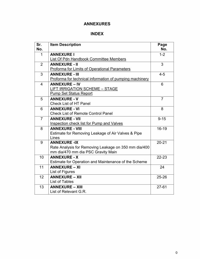
0
ANNEXURES
INDEX
Sr. No.
Item Description Page No.
1 ANNEXURE I List Of Pdn Handbook Committee Members
1-2
2 ANNEXURE - II Proforma for Limits of Operational Parameters
3
3 ANNEXURE - III Proforma for technical information of pumping machinery
4-5
4 ANNEXURE – IV LIFT IRRIGATION SCHEME – STAGE Pump Set Status Report
6
5 ANNEXURE - V Check List of HT Panel
7
6 ANNEXURE - VI Check List of Remote Control Panel
8
7 ANNEXURE - VII Inspection check list for Pump and Valves
9-15
8 ANNEXURE - VIII Estimate for Removing Leakage of Air Valves & Pipe Lines
16-19
9 ANNEXURE -IX Rate Analysis for Removing Leakage on 350 mm dia/400 mm dia/470 mm dia PSC Gravity Main
20-21
10 ANNEXURE - X Estimate for Operation and Maintenance of the Scheme
22-23
11 ANNEXURE – XI List of Figures
24
12 ANNEXURE – XII List of Tables
25-26
13 ANNEXURE – XIII List of Relevant G.R.
27-61
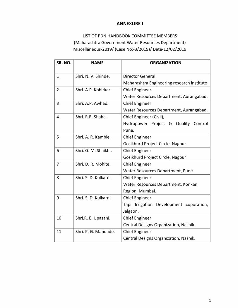
1
ANNEXURE I
LIST OF PDN HANDBOOK COMMITTEE MEMBERS (Maharashtra Government Water Resources Department) Miscellaneous-2019/ (Case No:-3/2019)/ Date-12/02/2019
SR. NO. NAME ORGANIZATION
1 Shri. N. V. Shinde. Director General
Maharashtra Engineering research institute 2 Shri. A.P. Kohirkar. Chief Engineer
Water Resources Department, Aurangabad. 3 Shri. A.P. Awhad. Chief Engineer
Water Resources Department, Aurangabad. 4 Shri. R.R. Shaha. Chief Engineer (Civil),
Hydropower Project & Quality Control Pune.
5 Shri. A. R. Kamble. Chief Engineer Gosikhurd Project Circle, Nagpur
6 Shri. G. M. Shaikh.. Chief Engineer Gosikhurd Project Circle, Nagpur
7 Shri. D. R. Mohite. Chief Engineer Water Resources Department, Pune.
8 Shri. S. D. Kulkarni. Chief Engineer Water Resources Department, Konkan Region, Mumbai.
9 Shri. S. D. Kulkarni. Chief Engineer Tapi Irrigation Development coporation, Jalgaon.
10 Shri.R. E. Upasani. Chief Engineer Central Designs Organization, Nashik.
11 Shri. P. G. Mandade. Chief Engineer Central Designs Organization, Nashik.
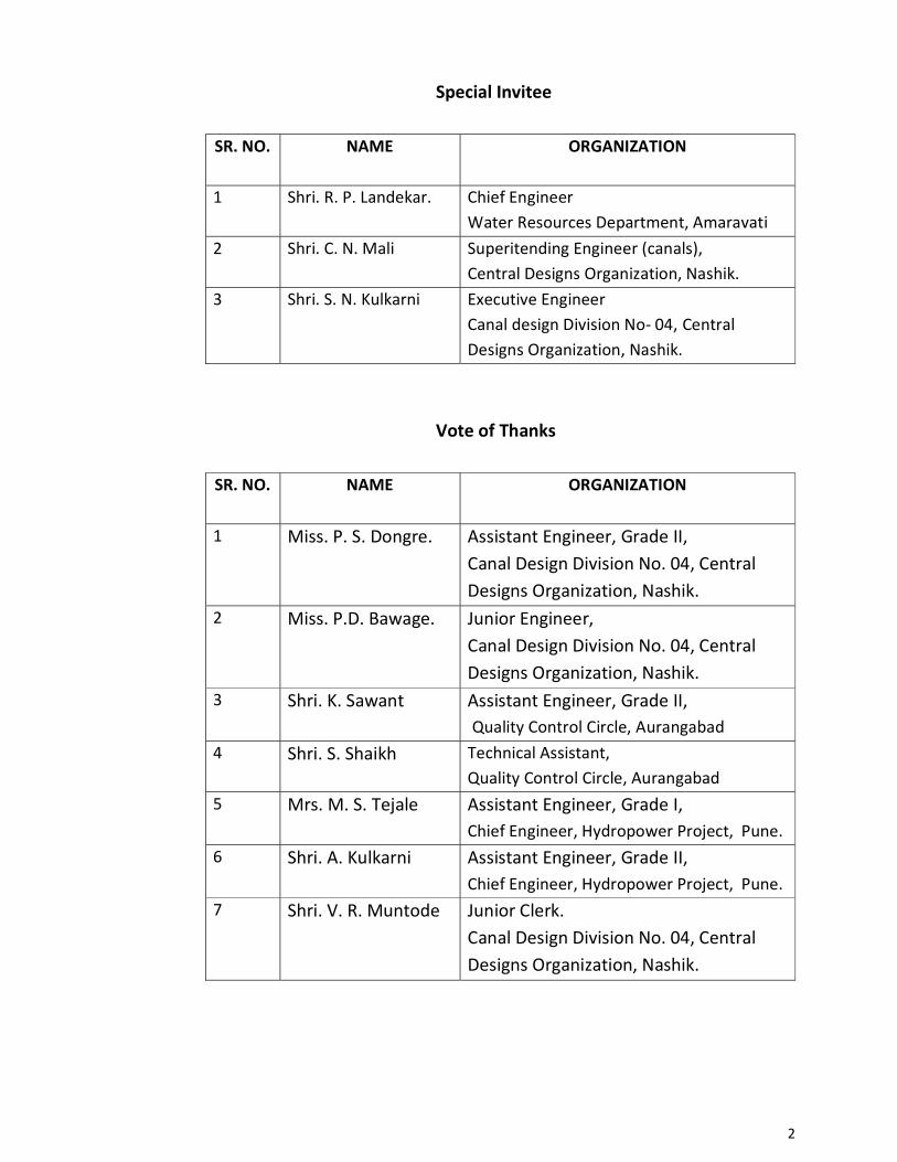
2
Special Invitee
SR. NO. NAME ORGANIZATION
1 Shri. R. P. Landekar. Chief Engineer Water Resources Department, Amaravati
2 Shri. C. N. Mali Superitending Engineer (canals), Central Designs Organization, Nashik.
3 Shri. S. N. Kulkarni Executive Engineer Canal design Division No- 04, Central Designs Organization, Nashik.
Vote of Thanks
SR. NO. NAME ORGANIZATION
1 Miss. P. S. Dongre. Assistant Engineer, Grade II, Canal Design Division No. 04, Central Designs Organization, Nashik.
2 Miss. P.D. Bawage. Junior Engineer, Canal Design Division No. 04, Central Designs Organization, Nashik.
3 Shri. K. Sawant Assistant Engineer, Grade II, Quality Control Circle, Aurangabad
4 Shri. S. Shaikh Technical Assistant, Quality Control Circle, Aurangabad
5 Mrs. M. S. Tejale Assistant Engineer, Grade I, Chief Engineer, Hydropower Project, Pune.
6 Shri. A. Kulkarni Assistant Engineer, Grade II, Chief Engineer, Hydropower Project, Pune.
7 Shri. V. R. Muntode Junior Clerk. Canal Design Division No. 04, Central Designs Organization, Nashik.
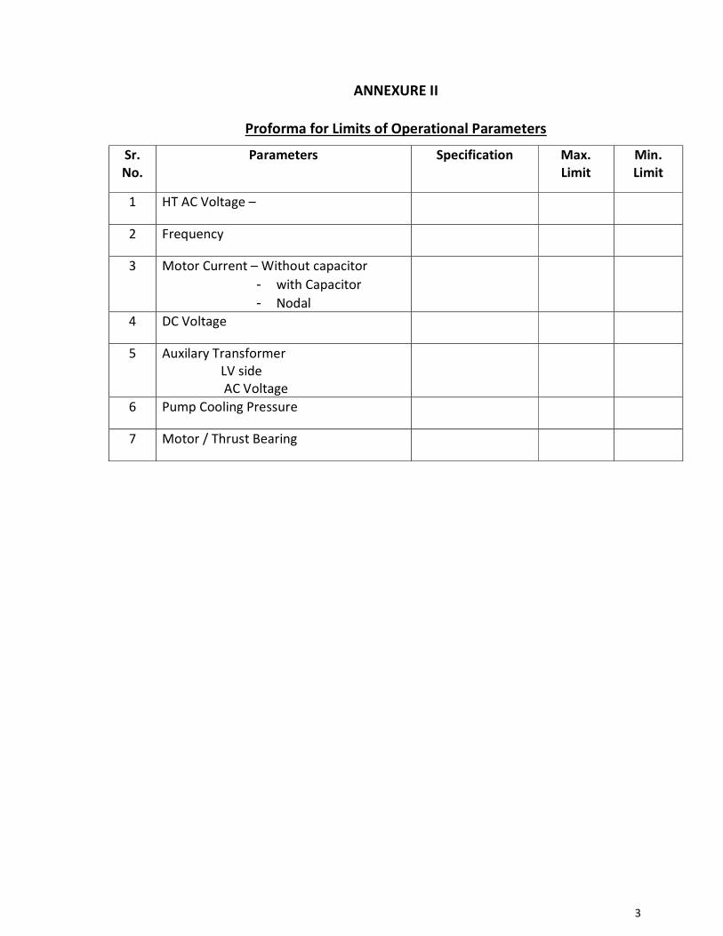
3
ANNEXURE II
Proforma for Limits of Operational Parameters
Sr. No.
Parameters Specification Max. Limit
Min. Limit
1 HT AC Voltage –
2 Frequency
3 Motor Current – Without capacitor - with Capacitor - Nodal
4 DC Voltage
5 Auxilary Transformer LV side AC Voltage
6 Pump Cooling Pressure
7 Motor / Thrust Bearing
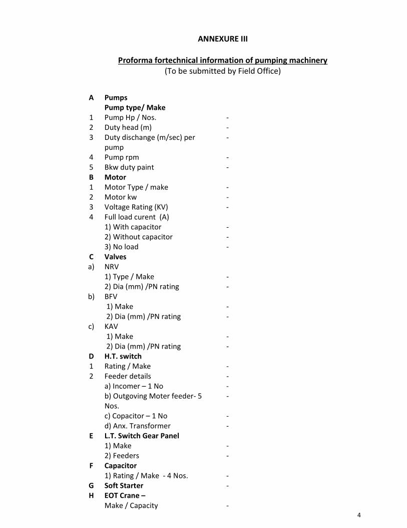
4
ANNEXURE III
Proforma fortechnical information of pumping machinery (To be submitted by Field Office)
A Pumps
Pump type/ Make
1 Pump Hp / Nos. - 2 Duty head (m) - 3 Duty dischange (m/sec) per
pump -
4 Pump rpm - 5 Bkw duty paint - B Motor 1 Motor Type / make - 2 Motor kw - 3 Voltage Rating (KV) - 4 Full load curent (A)
1) With capacitor 2) Without capacitor 3) No load
- - -
C Valves a) NRV
1) Type / Make 2) Dia (mm) /PN rating
- -
b) BFV 1) Make 2) Dia (mm) /PN rating
- -
c) KAV 1) Make 2) Dia (mm) /PN rating
- -
D H.T. switch 1 Rating / Make - 2 Feeder details - a) Incomer – 1 No - b) Outgoving Moter feeder- 5
Nos. -
c) Copacitor – 1 No - d) Anx. Transformer -
E L.T. Switch Gear Panel 1) Make - 2) Feeders -
F Capacitor 1) Rating / Make - 4 Nos. -
G Soft Starter - H EOT Crane –
Make / Capacity -
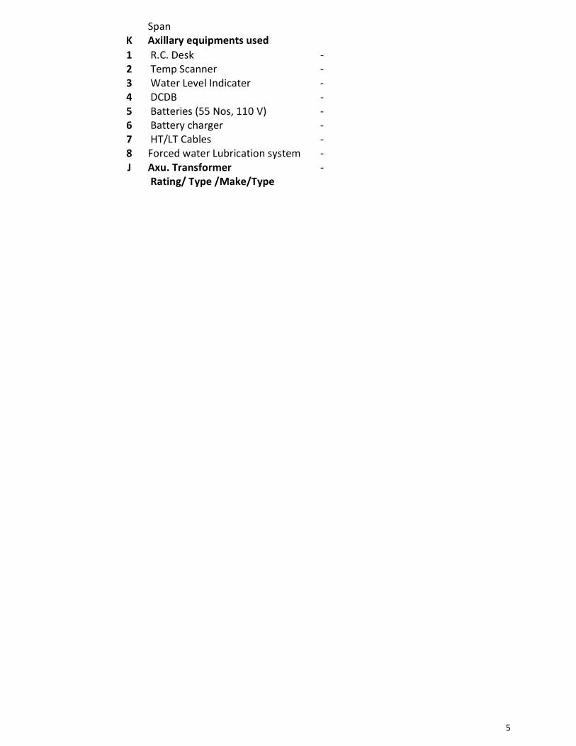
5
Span K Axillary equipments used 1 R.C. Desk - 2 Temp Scanner - 3 Water Level Indicater - 4 DCDB - 5 Batteries (55 Nos, 110 V) - 6 Battery charger - 7 HT/LT Cables - 8 Forced water Lubrication system - J Axu. Transformer
Rating/ Type /Make/Type -
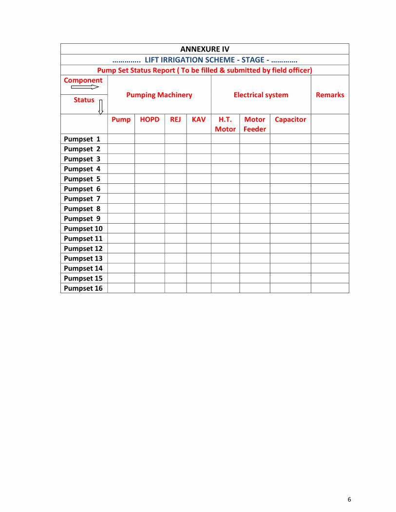
6
ANNEXURE IV ………….. LIFT IRRIGATION SCHEME - STAGE - ………….
Pump Set Status Report ( To be filled & submitted by field officer) Component
Pumping Machinery Electrical system Remarks Status
Pump HOPD REJ KAV H.T.
Motor Motor Feeder
Capacitor
Pumpset 1 Pumpset 2 Pumpset 3 Pumpset 4 Pumpset 5 Pumpset 6 Pumpset 7 Pumpset 8 Pumpset 9 Pumpset 10 Pumpset 11 Pumpset 12 Pumpset 13 Pumpset 14 Pumpset 15 Pumpset 16
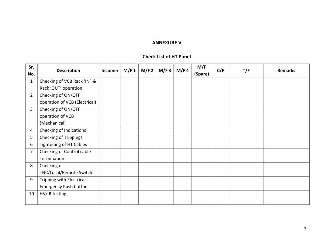
7
ANNEXURE V
Check List of HT Panel
Sr.No.
Description Incomer M/F 1 M/F 2 M/F 3 M/F 4 M/F
(Spare) C/F T/F Remarks
1 Checking of VCB Rack ‘IN’ & Rack ‘OUT’ operation
2 Checking of ON/OFF operation of VCB (Electrical)
3 Checking of ON/OFF operation of VCB (Mechanical)
4 Checking of Indications 5 Checking of Trippings 6 Tightening of HT Cables 7 Checking of Control cable
Termination
8 Checking of TNC/Local/Remote Switch.
9 Tripping with Electrical Emergency Push button
10
HV/IR testing
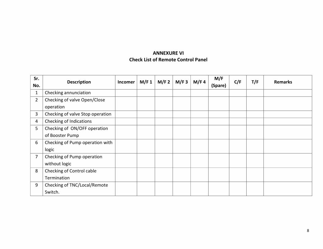
8
ANNEXURE VI Check List of Remote Control Panel
Sr.No.
Description Incomer M/F 1 M/F 2 M/F 3 M/F 4 M/F
(Spare) C/F T/F Remarks
1 Checking annunciation 2 Checking of valve Open/Close
operation
3 Checking of valve Stop operation 4 Checking of Indications 5 Checking of ON/OFF operation
of Booster Pump
6 Checking of Pump operation with logic
7 Checking of Pump operation without logic
8 Checking of Control cable Termination
9 Checking of TNC/Local/Remote Switch.
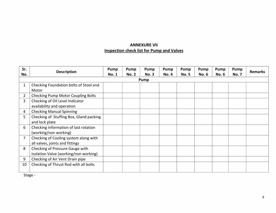
9
ANNEXURE VII Inspection check list for Pump and Valves
Stage -
Sr.No. Description Pump
No. 1 Pump No. 2
Pump No. 3
Pump No. 4
Pump No. 5
Pump No. 6
Pump No. 6
Pump No. 7 Remarks
Pump 1 Checking Foundation bolts of Stool and
Motor
2 Checking Pump Motor Coupling Bolts 3 Checking of Oil Level Indicator
availability and operation
4 Checking Manual Spinning 5 Checking of Stuffing Box, Gland packing
and lock plate
6 Checking information of last rotation (working/non working)
7 Checking of Cooling system along with all valves, joints and fittings
8 Checking of Pressure Gauge with Isolation Valve (working/non working)
9 Checking of Air Vent Drain pipe 10
Checking of Thrust Rod with all bolts
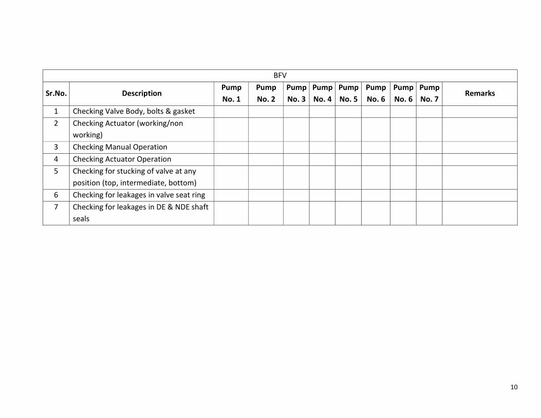
10
BFV
Sr.No. Description Pump No. 1
Pump No. 2
Pump No. 3
Pump No. 4
Pump No. 5
Pump No. 6
Pump No. 6
Pump No. 7
Remarks
1 Checking Valve Body, bolts & gasket 2 Checking Actuator (working/non
working)
3 Checking Manual Operation 4 Checking Actuator Operation 5 Checking for stucking of valve at any
position (top, intermediate, bottom)
6 Checking for leakages in valve seat ring 7 Checking for leakages in DE & NDE shaft
seals
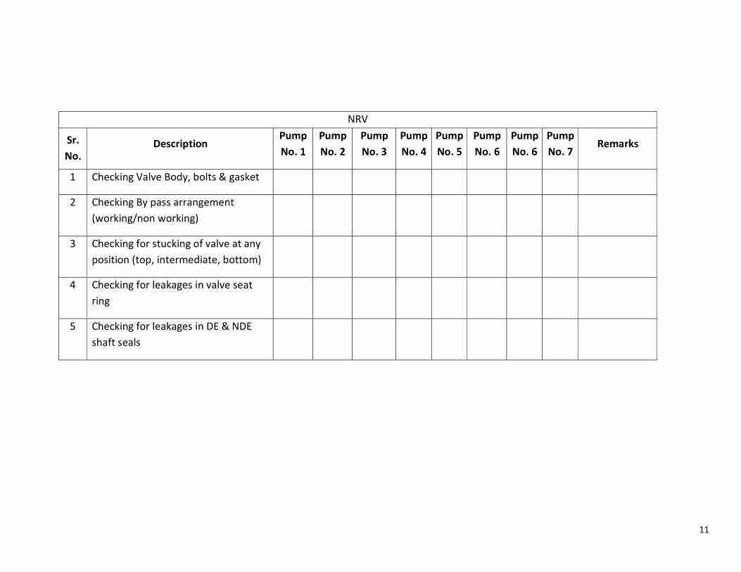
11
NRV
Sr. No.
Description Pump No. 1
Pump No. 2
Pump No. 3
Pump No. 4
Pump No. 5
Pump No. 6
Pump No. 6
Pump No. 7
Remarks
1 Checking Valve Body, bolts & gasket
2 Checking By pass arrangement (working/non working)
3 Checking for stucking of valve at any position (top, intermediate, bottom)
4 Checking for leakages in valve seat ring
5 Checking for leakages in DE & NDE shaft seals
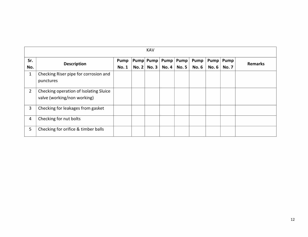
12
KAV
Sr. No.
Description Pump No. 1
Pump No. 2
Pump No. 3
Pump No. 4
Pump No. 5
Pump No. 6
Pump No. 6
Pump No. 7
Remarks
1 Checking Riser pipe for corrosion and punctures
2 Checking operation of Isolating Sluice valve (working/non working)
3 Checking for leakages from gasket
4 Checking for nut bolts
5 Checking for orifice & timber balls
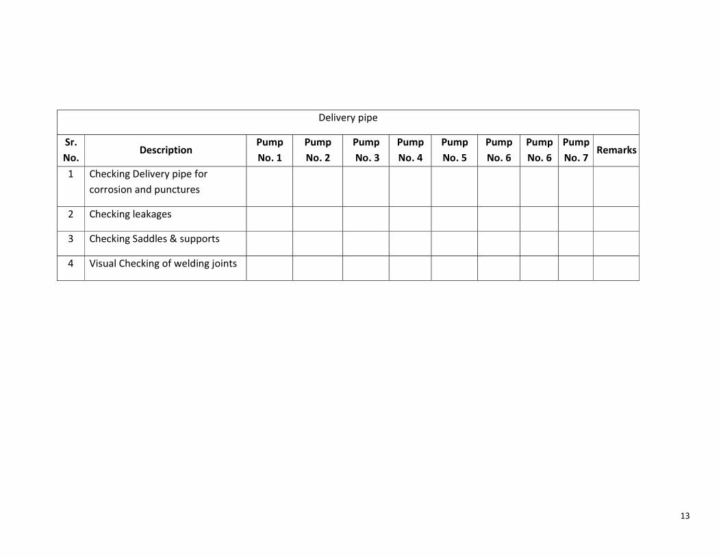
13
Delivery pipe
Sr. No.
Description Pump No. 1
Pump No. 2
Pump No. 3
Pump No. 4
Pump No. 5
Pump No. 6
Pump No. 6
Pump No. 7
Remarks
1 Checking Delivery pipe for corrosion and punctures
2 Checking leakages
3 Checking Saddles & supports
4 Visual Checking of welding joints
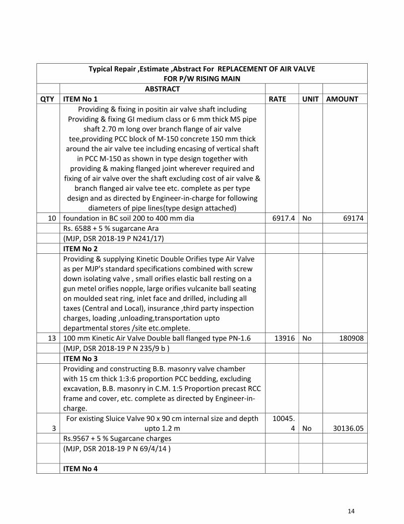
14
Typical Repair ,Estimate ,Abstract For REPLACEMENT OF AIR VALVE FOR P/W RISING MAIN
ABSTRACT QTY ITEM No 1 RATE UNIT AMOUNT
Providing & fixing in positin air valve shaft including Providing & fixing GI medium class or 6 mm thick MS pipe
shaft 2.70 m long over branch flange of air valve tee,providing PCC block of M-150 concrete 150 mm thick
around the air valve tee including encasing of vertical shaft in PCC M-150 as shown in type design together with
providing & making flanged joint wherever required and fixing of air valve over the shaft excluding cost of air valve &
branch flanged air valve tee etc. complete as per type design and as directed by Engineer-in-charge for following
diameters of pipe lines(type design attached) 10 foundation in BC soil 200 to 400 mm dia 6917.4 No 69174
Rs. 6588 + 5 % sugarcane Ara (MJP, DSR 2018-19 P N241/17) ITEM No 2
Providing & supplying Kinetic Double Orifies type Air Valve as per MJP's standard specifications combined with screw down isolating valve , small orifies elastic ball resting on a gun metel orifies nopple, large orifies vulcanite ball seating on moulded seat ring, inlet face and drilled, including all taxes (Central and Local), insurance ,third party inspection charges, loading ,unloading,transportation upto departmental stores /site etc.omplete.
13 100 mm Kinetic Air Valve Double ball flanged type PN-1.6 13916 No 180908 (MJP, DSR 2018-19 P N 235/9 b ) ITEM No 3
Providing and constructing B.B. masonry valve chamber with 15 cm thick 1:3:6 proportion PCC bedding, excluding excavation, B.B. masonry in C.M. 1:5 Proportion precast RCC frame and cover, etc. complete as directed by Engineer-in-charge.
3 For existing Sluice Valve 90 x 90 cm internal size and depth
upto 1.2 m 10045.
4 No 30136.05 Rs.9567 + 5 % Sugarcane charges
(MJP, DSR 2018-19 P N 69/4/14 )
ITEM No 4
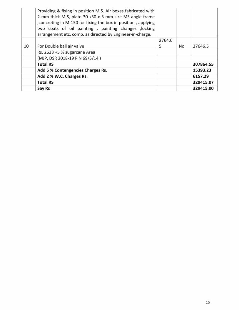
15
Providing & fixing in position M.S. Air boxes fabricated with 2 mm thick M.S, plate 30 x30 x 3 mm size MS angle frame ,concreting in M-150 for fixing the box in position , applying two coats of oil painting , painting changes ,locking arrangement etc. comp. as directed by Engineer-in-charge.
10 For Double ball air valve 2764.65 No 27646.5
Rs. 2633 +5 % sugarcane Area (MJP, DSR 2018-19 P N 69/5/14 ) Total RS 307864.55 Add 5 % Contengencies Charges Rs. 15393.23 Add 2 % W.C. Charges Rs. 6157.29 Total RS 329415.07 Say Rs 329415.00
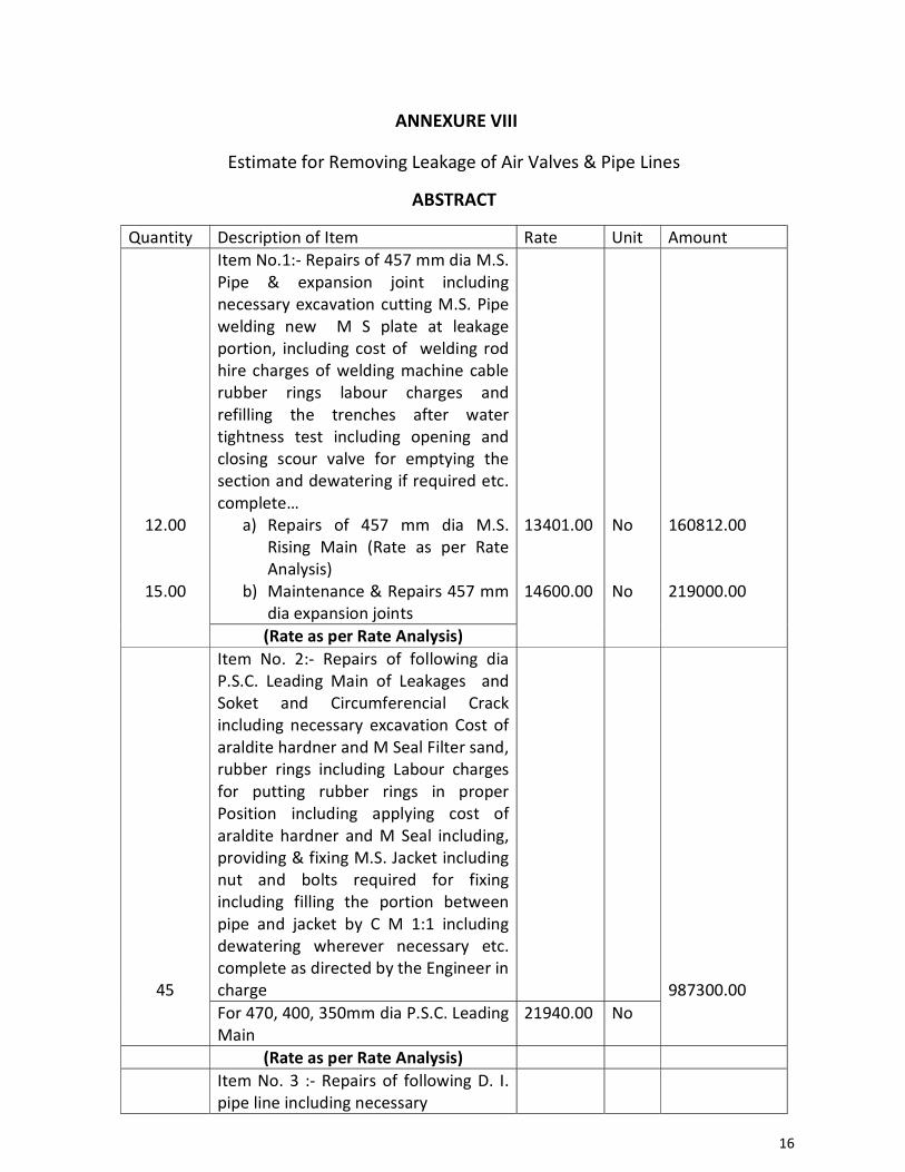
16
ANNEXURE VIII
Estimate for Removing Leakage of Air Valves & Pipe Lines
ABSTRACT
Quantity Description of Item Rate Unit Amount
12.00
15.00
Item No.1:- Repairs of 457 mm dia M.S. Pipe & expansion joint including necessary excavation cutting M.S. Pipe welding new M S plate at leakage portion, including cost of welding rod hire charges of welding machine cable rubber rings labour charges and refilling the trenches after water tightness test including opening and closing scour valve for emptying the section and dewatering if required etc. complete…
a) Repairs of 457 mm dia M.S. Rising Main (Rate as per Rate Analysis)
b) Maintenance & Repairs 457 mm dia expansion joints
13401.00 14600.00
No No
160812.00 219000.00
(Rate as per Rate Analysis)
45
Item No. 2:- Repairs of following dia P.S.C. Leading Main of Leakages and Soket and Circumferencial Crack including necessary excavation Cost of araldite hardner and M Seal Filter sand, rubber rings including Labour charges for putting rubber rings in proper Position including applying cost of araldite hardner and M Seal including, providing & fixing M.S. Jacket including nut and bolts required for fixing including filling the portion between pipe and jacket by C M 1:1 including dewatering wherever necessary etc. complete as directed by the Engineer in charge
987300.00
For 470, 400, 350mm dia P.S.C. Leading Main
21940.00 No
(Rate as per Rate Analysis)
Item No. 3 :- Repairs of following D. I. pipe line including necessary
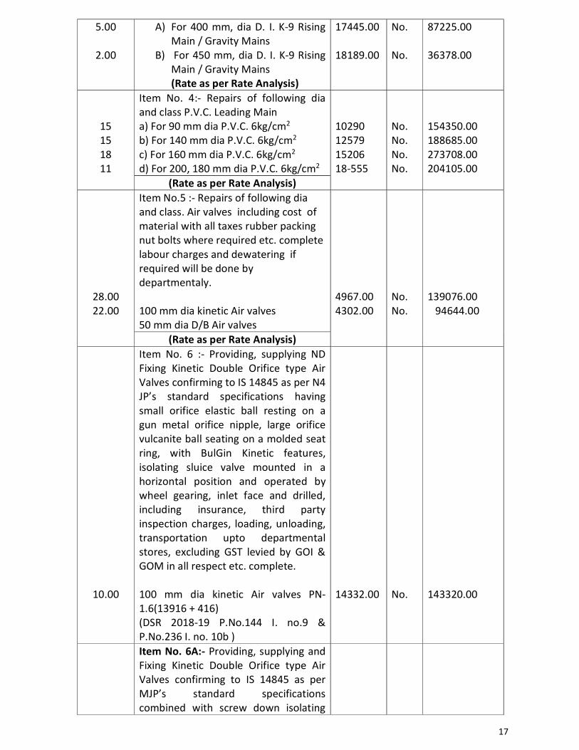
17
5.00
2.00
A) For 400 mm, dia D. I. K-9 Rising Main / Gravity Mains
B) For 450 mm, dia D. I. K-9 Rising Main / Gravity Mains (Rate as per Rate Analysis)
17445.00 18189.00
No. No.
87225.00 36378.00
15 15 18 11
Item No. 4:- Repairs of following dia and class P.V.C. Leading Main a) For 90 mm dia P.V.C. 6kg/cm2 b) For 140 mm dia P.V.C. 6kg/cm2 c) For 160 mm dia P.V.C. 6kg/cm2 d) For 200, 180 mm dia P.V.C. 6kg/cm2
10290 12579 15206 18-555
No. No. No. No.
154350.00 188685.00 273708.00 204105.00
(Rate as per Rate Analysis)
28.00 22.00
Item No.5 :- Repairs of following dia and class. Air valves including cost of material with all taxes rubber packing nut bolts where required etc. complete labour charges and dewatering if required will be done by departmentaly. 100 mm dia kinetic Air valves 50 mm dia D/B Air valves
4967.00 4302.00
No. No.
139076.00 94644.00
(Rate as per Rate Analysis)
10.00
Item No. 6 :- Providing, supplying ND Fixing Kinetic Double Orifice type Air Valves confirming to IS 14845 as per N4 JP’s standard specifications having small orifice elastic ball resting on a gun metal orifice nipple, large orifice vulcanite ball seating on a molded seat ring, with BulGin Kinetic features, isolating sluice valve mounted in a horizontal position and operated by wheel gearing, inlet face and drilled, including insurance, third party inspection charges, loading, unloading, transportation upto departmental stores, excluding GST levied by GOI & GOM in all respect etc. complete. 100 mm dia kinetic Air valves PN-1.6(13916 + 416) (DSR 2018-19 P.No.144 I. no.9 & P.No.236 I. no. 10b )
14332.00
No.
143320.00
Item No. 6A:- Providing, supplying and Fixing Kinetic Double Orifice type Air Valves confirming to IS 14845 as per MJP’s standard specifications combined with screw down isolating
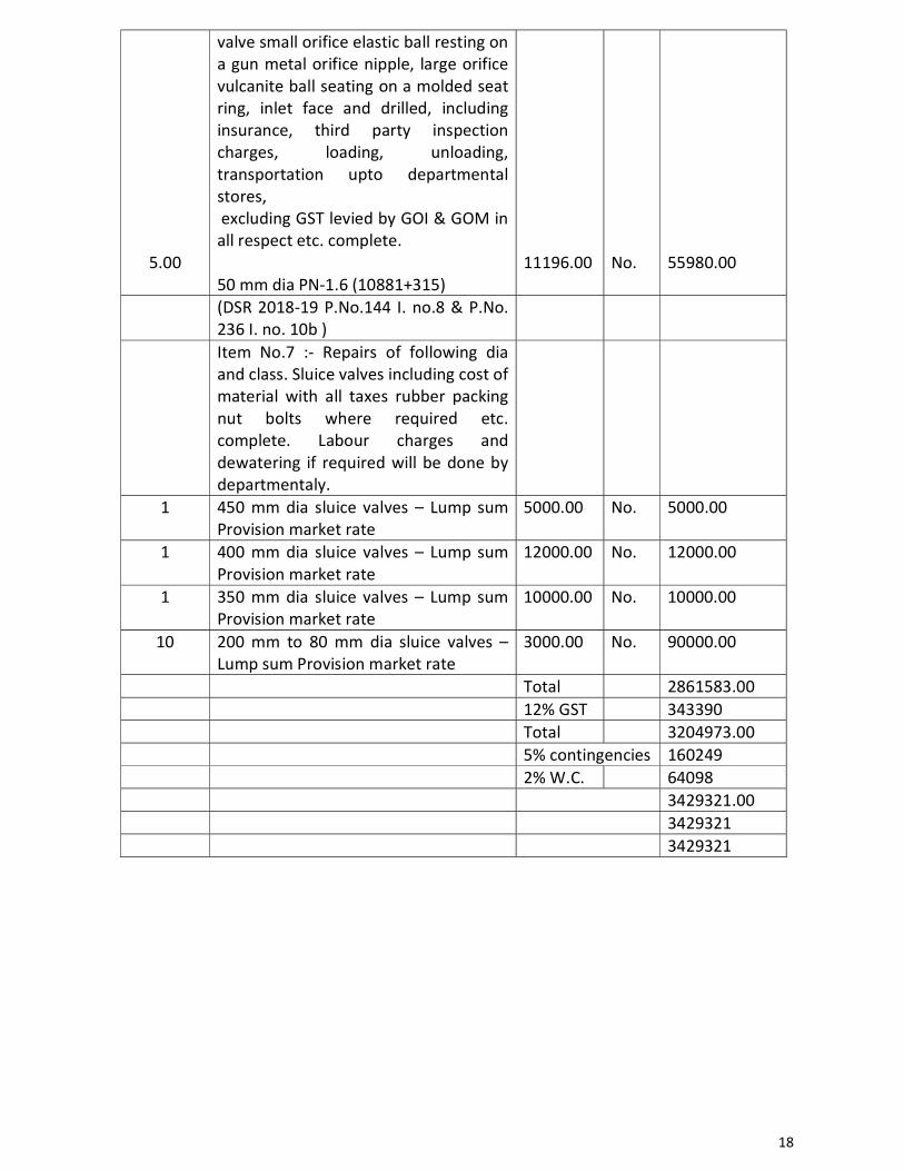
18
5.00
valve small orifice elastic ball resting on a gun metal orifice nipple, large orifice vulcanite ball seating on a molded seat ring, inlet face and drilled, including insurance, third party inspection charges, loading, unloading, transportation upto departmental stores, excluding GST levied by GOI & GOM in all respect etc. complete. 50 mm dia PN-1.6 (10881+315)
11196.00
No.
55980.00
(DSR 2018-19 P.No.144 I. no.8 & P.No. 236 I. no. 10b )
Item No.7 :- Repairs of following dia and class. Sluice valves including cost of material with all taxes rubber packing nut bolts where required etc. complete. Labour charges and dewatering if required will be done by departmentaly.
1 450 mm dia sluice valves – Lump sum Provision market rate
5000.00 No. 5000.00
1 400 mm dia sluice valves – Lump sum Provision market rate
12000.00 No. 12000.00
1 350 mm dia sluice valves – Lump sum Provision market rate
10000.00 No. 10000.00
10 200 mm to 80 mm dia sluice valves – Lump sum Provision market rate
3000.00 No. 90000.00
Total 2861583.00 12% GST 343390 Total 3204973.00 5% contingencies 160249 2% W.C. 64098 3429321.00 3429321 3429321
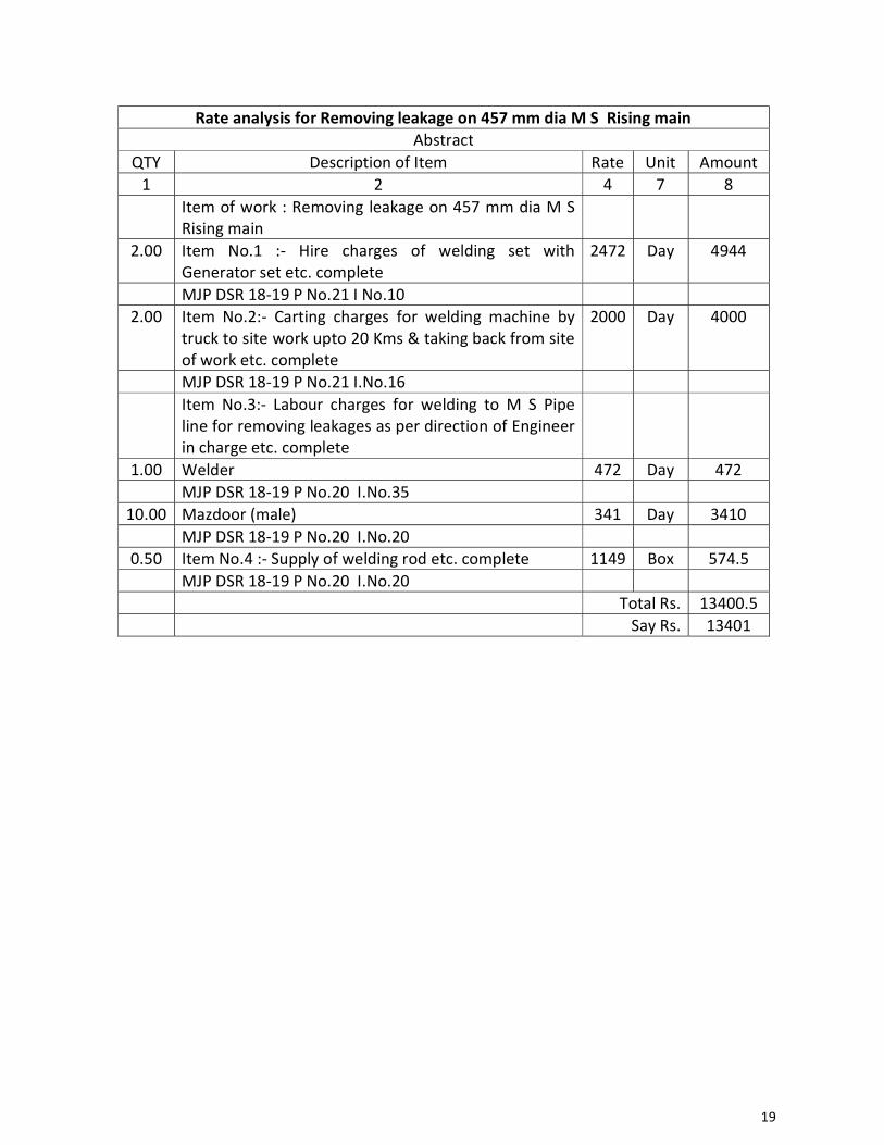
19
Rate analysis for Removing leakage on 457 mm dia M S Rising main Abstract
QTY Description of Item Rate Unit Amount 1 2 4 7 8 Item of work : Removing leakage on 457 mm dia M S
Rising main
2.00 Item No.1 :- Hire charges of welding set with Generator set etc. complete
2472 Day 4944
MJP DSR 18-19 P No.21 I No.10 2.00 Item No.2:- Carting charges for welding machine by
truck to site work upto 20 Kms & taking back from site of work etc. complete
2000 Day 4000
MJP DSR 18-19 P No.21 I.No.16 Item No.3:- Labour charges for welding to M S Pipe
line for removing leakages as per direction of Engineer in charge etc. complete
1.00 Welder 472 Day 472 MJP DSR 18-19 P No.20 I.No.35
10.00 Mazdoor (male) 341 Day 3410 MJP DSR 18-19 P No.20 I.No.20
0.50 Item No.4 :- Supply of welding rod etc. complete 1149 Box 574.5 MJP DSR 18-19 P No.20 I.No.20 Total Rs. 13400.5 Say Rs. 13401
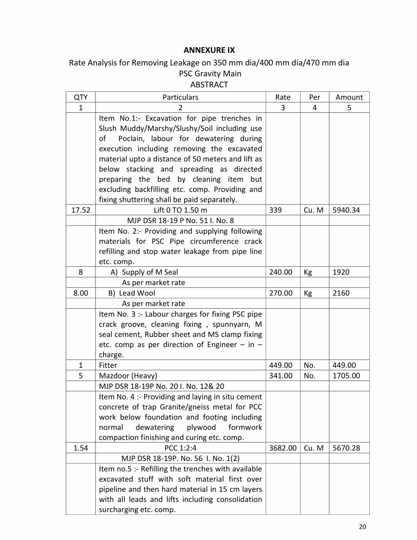
20
ANNEXURE IX
Rate Analysis for Removing Leakage on 350 mm dia/400 mm dia/470 mm dia PSC Gravity Main
ABSTRACT QTY Particulars Rate Per Amount
1 2 3 4 5 Item No.1:- Excavation for pipe trenches in
Slush Muddy/Marshy/Slushy/Soil including use of Poclain, labour for dewatering during execution including removing the excavated material upto a distance of 50 meters and lift as below stacking and spreading as directed preparing the bed by cleaning item but excluding backfilling etc. comp. Providing and fixing shuttering shall be paid separately.
17.52 Lift 0 TO 1.50 m 339 Cu. M 5940.34 MJP DSR 18-19 P No. 51 I. No. 8 Item No. 2:- Providing and supplying following
materials for PSC Pipe circumference crack refilling and stop water leakage from pipe line etc. comp.
8 A) Supply of M Seal 240.00 Kg 1920 As per market rate
8.00 B) Lead Wool 270.00 Kg 2160 As per market rate Item No. 3 :- Labour charges for fixing PSC pipe
crack groove, cleaning fixing , spunnyarn, M seal cement, Rubber sheet and MS clamp fixing etc. comp as per direction of Engineer – in – charge.
1 Fitter 449.00 No. 449.00 5 Mazdoor (Heavy) 341.00 No. 1705.00 MJP DSR 18-19P No. 20 I. No. 12& 20 Item No. 4 :- Providing and laying in situ cement
concrete of trap Granite/gneiss metal for PCC work below foundation and footing including normal dewatering plywood formwork compaction finishing and curing etc. comp.
1.54 PCC 1:2:4 3682.00 Cu. M 5670.28 MJP DSR 18-19P. No. 56 I. No. 1(2) Item no.5 :- Refilling the trenches with available
excavated stuff with soft material first over pipeline and then hard material in 15 cm layers with all leads and lifts including consolidation surcharging etc. comp.
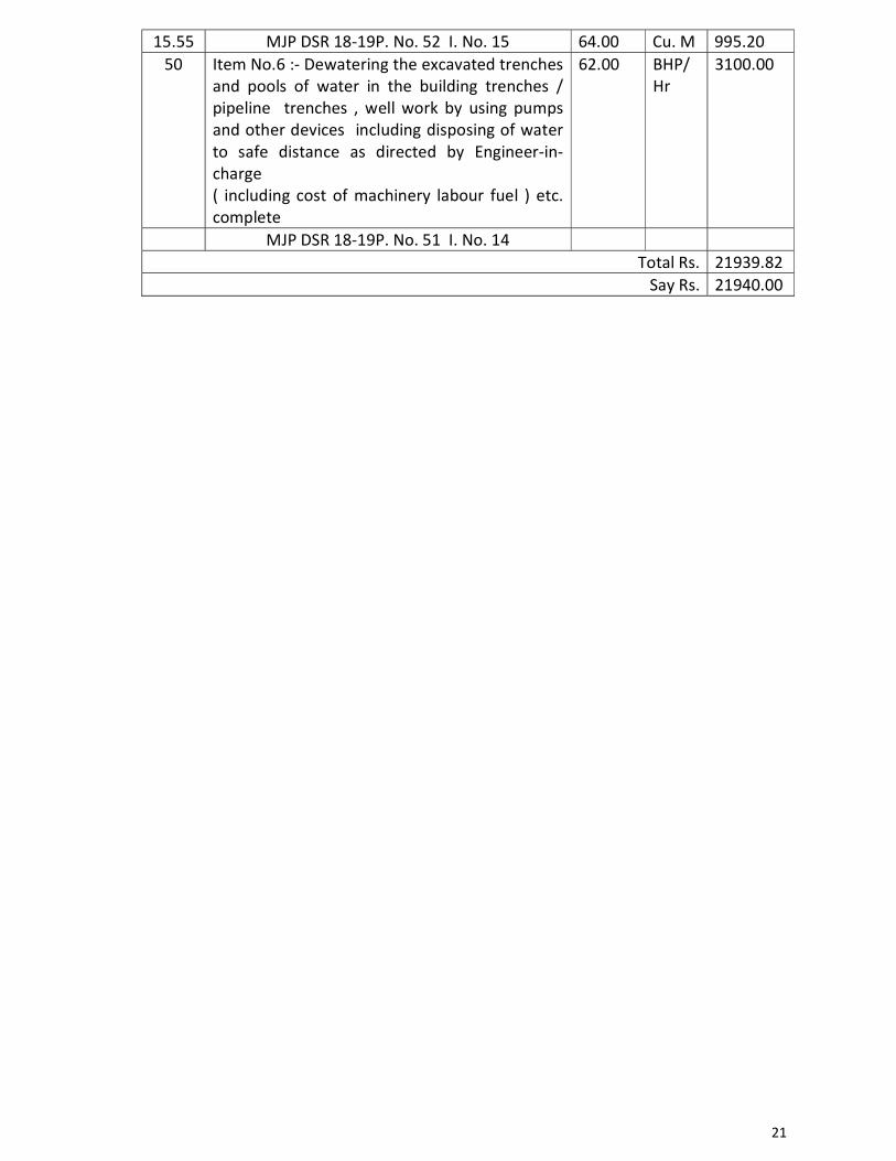
21
15.55 MJP DSR 18-19P. No. 52 I. No. 15 64.00 Cu. M 995.20 50 Item No.6 :- Dewatering the excavated trenches
and pools of water in the building trenches / pipeline trenches , well work by using pumps and other devices including disposing of water to safe distance as directed by Engineer-in-charge ( including cost of machinery labour fuel ) etc. complete
62.00 BHP/Hr
3100.00
MJP DSR 18-19P. No. 51 I. No. 14 Total Rs. 21939.82
Say Rs. 21940.00
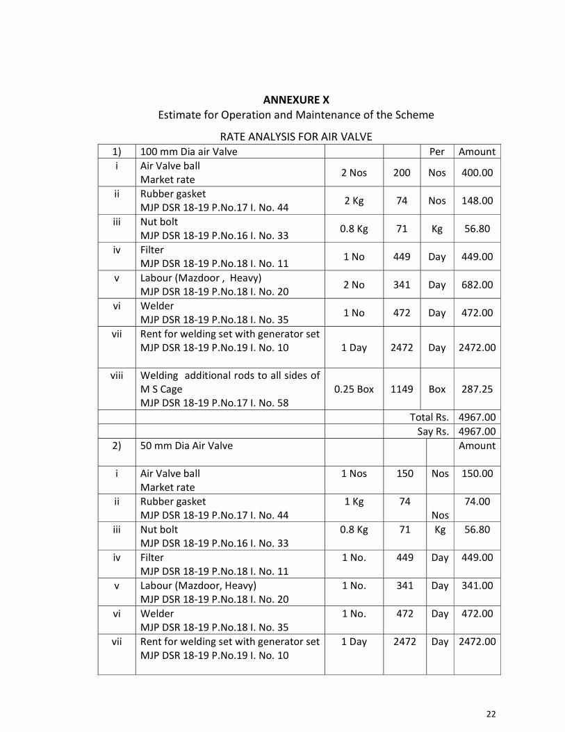
22
ANNEXURE X Estimate for Operation and Maintenance of the Scheme
RATE ANALYSIS FOR AIR VALVE 1) 100 mm Dia air Valve Per Amount i Air Valve ball
Market rate 2 Nos 200 Nos 400.00
ii Rubber gasket MJP DSR 18-19 P.No.17 I. No. 44
2 Kg 74 Nos 148.00
iii Nut bolt MJP DSR 18-19 P.No.16 I. No. 33
0.8 Kg 71 Kg 56.80
iv Filter MJP DSR 18-19 P.No.18 I. No. 11
1 No 449 Day 449.00
v Labour (Mazdoor , Heavy) MJP DSR 18-19 P.No.18 I. No. 20
2 No 341 Day 682.00
vi Welder MJP DSR 18-19 P.No.18 I. No. 35
1 No 472 Day 472.00
vii Rent for welding set with generator set MJP DSR 18-19 P.No.19 I. No. 10 1 Day 2472 Day 2472.00
viii Welding additional rods to all sides of M S Cage MJP DSR 18-19 P.No.17 I. No. 58
0.25 Box 1149 Box 287.25
Total Rs. 4967.00 Say Rs. 4967.00
2) 50 mm Dia Air Valve Amount
i Air Valve ball Market rate
1 Nos 150 Nos 150.00
ii Rubber gasket MJP DSR 18-19 P.No.17 I. No. 44
1 Kg 74 Nos
74.00
iii Nut bolt MJP DSR 18-19 P.No.16 I. No. 33
0.8 Kg 71 Kg 56.80
iv Filter MJP DSR 18-19 P.No.18 I. No. 11
1 No. 449 Day 449.00
v Labour (Mazdoor, Heavy) MJP DSR 18-19 P.No.18 I. No. 20
1 No. 341 Day 341.00
vi Welder MJP DSR 18-19 P.No.18 I. No. 35
1 No. 472 Day 472.00
vii Rent for welding set with generator set MJP DSR 18-19 P.No.19 I. No. 10
1 Day 2472 Day 2472.00
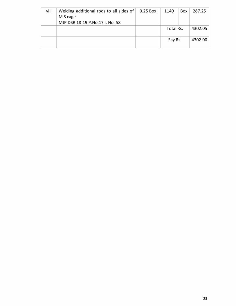
23
viii Welding additional rods to all sides of M S cage MJP DSR 18-19 P.No.17 I. No. 58
0.25 Box 1149 Box 287.25
Total Rs. 4302.05
Say Rs. 4302.00
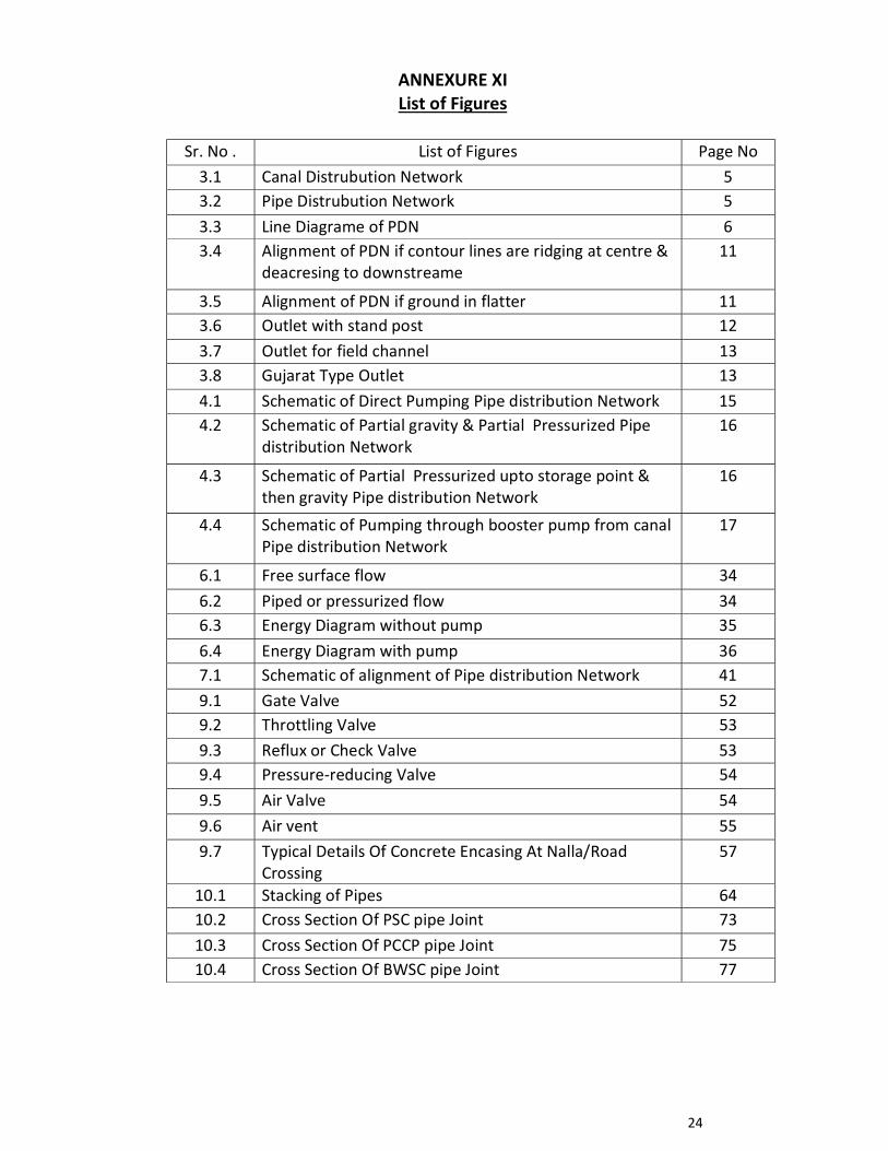
24
ANNEXURE XI List of Figures
Sr. No . List of Figures Page No 3.1 Canal Distrubution Network 5 3.2 Pipe Distrubution Network 5 3.3 Line Diagrame of PDN 6 3.4 Alignment of PDN if contour lines are ridging at centre &
deacresing to downstreame 11
3.5 Alignment of PDN if ground in flatter 11 3.6 Outlet with stand post 12 3.7 Outlet for field channel 13 3.8 Gujarat Type Outlet 134.1 Schematic of Direct Pumping Pipe distribution Network 15 4.2 Schematic of Partial gravity & Partial Pressurized Pipe
distribution Network 16
4.3 Schematic of Partial Pressurized upto storage point & then gravity Pipe distribution Network
16
4.4 Schematic of Pumping through booster pump from canal Pipe distribution Network
17
6.1 Free surface flow 34 6.2 Piped or pressurized flow 34 6.3 Energy Diagram without pump 35 6.4 Energy Diagram with pump 36 7.1 Schematic of alignment of Pipe distribution Network 41 9.1 Gate Valve 52 9.2 Throttling Valve 539.3 Reflux or Check Valve 53 9.4 Pressure-reducing Valve 549.5 Air Valve 54 9.6 Air vent 55 9.7 Typical Details Of Concrete Encasing At Nalla/Road
Crossing 57
10.1 Stacking of Pipes 6410.2 Cross Section Of PSC pipe Joint 7310.3 Cross Section Of PCCP pipe Joint 7510.4 Cross Section Of BWSC pipe Joint 77
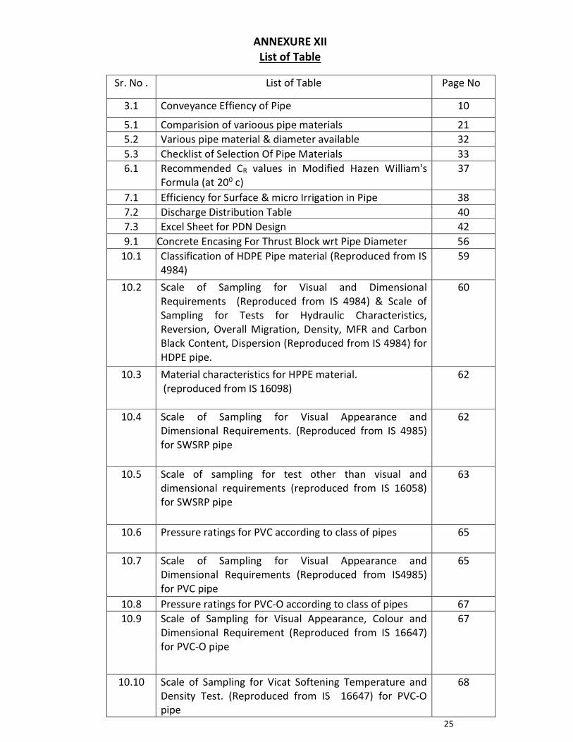
25
ANNEXURE XII
List of Table
Sr. No . List of Table Page No
3.1 Conveyance Effiency of Pipe 10
5.1 Comparision of varioous pipe materials 21 5.2 Various pipe material & diameter available 32 5.3 Checklist of Selection Of Pipe Materials 33 6.1 Recommended CR values in Modified Hazen William's
Formula (at 200 c) 37
7.1 Efficiency for Surface & micro Irrigation in Pipe 38 7.2 Discharge Distribution Table 40 7.3 Excel Sheet for PDN Design 42 9.1 Concrete Encasing For Thrust Block wrt Pipe Diameter 56
10.1 Classification of HDPE Pipe material (Reproduced from IS 4984)
59
10.2 Scale of Sampling for Visual and Dimensional Requirements (Reproduced from IS 4984) & Scale of Sampling for Tests for Hydraulic Characteristics, Reversion, Overall Migration, Density, MFR and Carbon Black Content, Dispersion (Reproduced from IS 4984) for HDPE pipe.
60
10.3 Material characteristics for HPPE material. (reproduced from IS 16098)
62
10.4 Scale of Sampling for Visual Appearance and Dimensional Requirements. (Reproduced from IS 4985) for SWSRP pipe
62
10.5 Scale of sampling for test other than visual and dimensional requirements (reproduced from IS 16058) for SWSRP pipe
63
10.6 Pressure ratings for PVC according to class of pipes
65
10.7 Scale of Sampling for Visual Appearance and Dimensional Requirements (Reproduced from IS4985) for PVC pipe
65
10.8 Pressure ratings for PVC-O according to class of pipes 67 10.9 Scale of Sampling for Visual Appearance, Colour and
Dimensional Requirement (Reproduced from IS 16647) for PVC-O pipe
67
10.10 Scale of Sampling for Vicat Softening Temperature and Density Test. (Reproduced from IS 16647) for PVC-O pipe
68
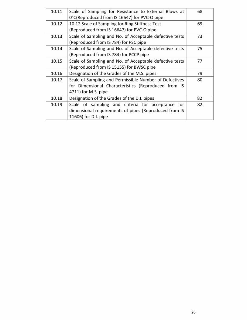
26
10.11 Scale of Sampling for Resistance to External Blows at 0°C(Reproduced from IS 16647) for PVC-O pipe
68
10.12 10.12 Scale of Sampling for Ring Stiffness Test (Reproduced from IS 16647) for PVC-O pipe
69
10.13 Scale of Sampling and No. of Acceptable defective tests (Reproduced from IS 784) for PSC pipe
73
10.14 Scale of Sampling and No. of Acceptable defective tests (Reproduced from IS 784) for PCCP pipe
75
10.15 Scale of Sampling and No. of Acceptable defective tests (Reproduced from IS 15155) for BWSC pipe
77
10.16 Designation of the Grades of the M.S. pipes 79 10.17 Scale of Sampling and Permissible Number of Defectives
for Dimensional Characteristics (Reproduced from IS 4711) for M.S. pipe
80
10.18 Designation of the Grades of the D.I. pipes 82 10.19 Scale of sampling and criteria for acceptance for
dimensional requirements of pipes (Reproduced from IS 11606) for D.I. pipe
82
27
ANNEXURE XIII
LIST OF RELEVANT GOVERNMENT RESOLUTIONS
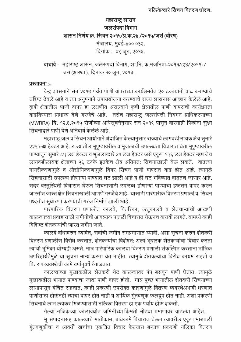
नलिकवदार सिचन लितरण धोरण.
महाराषटर शािन जििपदा लिभाग
शािन लनणणय कर. सिचन 2015/पर.कर.24 /2015/जि (धोरण) मतरािय, म बई-400 032. लदनाक :- 09 जन, 2016.
िाचाि : महाराषटर शािन, जििपदा लिभाग, शा.लन. कर.मजलनपरा-2011/(24/2011) / जि (आसथा.), लदनाक 10 जन, 2013.
परसतािना :- क दर शािनान िन 2017 पयत पाणी िापराचया कायणकषमतत 20 टककयानी िाढ करणयाच उलिषटट ठिि आह ि तया अन षगान उपाययोजना करणयाच राजय शािनाि आवहान किि आह. कषी कषतरातीि पाणी िापर हा िकषणीय अियायान कषी कषतरातीि पाणी िापराची कायणकषमता िाढलिणयाि पराधानय दण गरजच आह. तिच महाराषटर जििपतती लनयमन परालधकरणाचया (MWRRA) लद. 12.6.2015 रोजीचया अलधिचनन िार िन 2019 पािन बारमाही लपकाना ि कषम सिचनादवार पाणी दण अलनिायण किि आह.
महाराषटर जि ि सिचन आयोगान अदालजत कयायान िार राजयाच िागिडीिायक कषतर ि मार 225 िकष हकटर आह. राजयातीि भपषटठािरीि ि भजिाची उपिबधता लिचारात घता भपषटठािरीि पाणयातन ि मार 85 िकष हकटर ि भजिावदार 41 िकष हकटर अि एकण 126 िकष हकटर महणजच िागिडीिायक कषतराचया 56 टकक इतकच कषतर अलतमत: सिचनाखािी यऊ शकत. िाढतया नागरीकरणाम ळ ि औदयोलगकरणाम ळ लबगर सिचन पाणी िापरात िाढ होत आह. तयाम ळ सिचनािाठी उपिबध होणाऱया पाणयात घट झािी आह ि ही घट भलिषटयात िाढतच जाणार आह. िदर िसत ससथती लिचारात घऊन सिचनािाठी उपिबध होणाऱया पाणयाचा इषटटतम िापर करन जासतीत जासत कषतर सिचनाखािी आणण गरजच आह. यािाठी पारपारीक लितरण परणािी ि सिचन पधदतीत ि धारणा करणयाची गरज लनमाण झािी आह. पारपालरक लितरण परणािीत कािि, लितलरका, िघ कािि ि शतचाऱयाची आखणी कािवयाचया परिाहािाठी जमीनीची आिशयक पातळी लिचारात घऊनच करािी िागत. यामधय काही लिलशषटठ शतकऱयाची जासत जमीन जात.
कािि बाधािरन घयाित, ििाची जमीन िमपरमाणात घयािी, अशा िचना करन शतकरी लितरण परणािीि लिरोध करतात. शतकऱयाचा लिशषत: अयाप भधारक शतकऱयाचा लिचार करता तयाची भलमका योगयही अित. मातर पारपालरक काििा लितरण परणािी िकसयापत करताना तालतरक अपलरहायणतम ळ या िचना मानय करता यत नाहीत. तयाम ळ शतकऱयाचा लिरोध कायम राहतो ि लितरण वयिसथची काम िषान िष रगाळतात.
कािवयाचया म खाकडीि शतकरी थट कािवयािर पप बििन पाणी घतात. तयाम ळ म खाकडीि भागात पाणयाचा जादा पाणी िापर होतो. मातर प चछ भागातीि शतकरी सिचनाचया िाभापािन िलचत राहतात. काही परकरणी उपरोकत कारणाम ळ लितरण वयिसथअभािी धरणात पाणीिाठा होऊनही तयाचा िापर होत नाही ि आरथथक ग तिणक फिदर प होत नाही. अशा परकरणी सिचनाच िाभ ििकर लमळणयािाठी नलिका लितरण हा एक पयाय होऊ शकतो.
गयाया नलजकचया कािािधीत जलमनीचया सकमती मोठया परमाणािर िाढयाया आहत. भ-िपादनािह कािवयाच मातीकाम, बाधकाम लिचारात घऊन तयािरीि एकण भाडििी
ग तिणकीचा ि आिती खचाचा एकलतरत लिचार कयायाि बऱयाच परकरणी नलिका लितरण 28
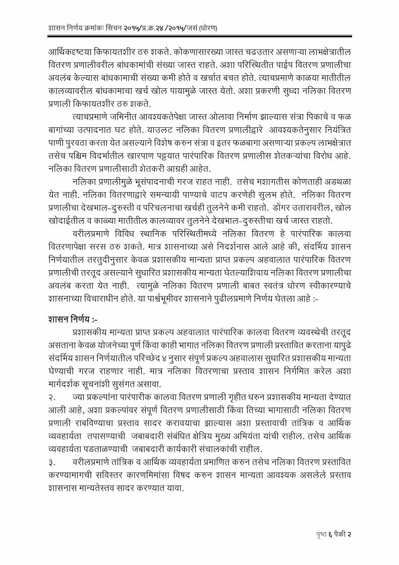
शािन लनणणय करमाकः सिचन 2015/पर.कर.24 /2015/जि (धोरण)
पषटठ 6 पकी 2
आरथथकदषटटया लकफायतशीर ठर शकत. कोकणािारखया जासत चढउतार अिणाऱया िाभकषतरातीि लितरण परणािीिरीि बाधकामाची िखया जासत राहत. अशा पलरससथतीत पाईप लितरण परणािीचा अििब कयायाि बाधकामाची िखया कमी होत ि खचात बचत होत. तयाचपरमाण काळया मातीतीि कािवयािरीि बाधकामाचा खचण खोि पायाम ळ जासत यतो. अशा परकरणी ि धदा नलिका लितरण परणािी लकफायतशीर ठर शकत.
तयाचपरमाण जलमनीत आिशयकतपकषा जासत ओिािा लनमाण झायायाि ितरा लपकाच ि फळ बागाचया उतपादनात घट होत. याउिट नलिका लितरण परणािीदवार आिशयकतन िार लनयलतरत पाणी प रिठा करता यत अियायान लिशष करन ितरा ि इतर फळबागा अिणाऱया परकयाप िाभकषतरात तिच पलिम लिदभातीि खारपाण पटटयात पारपालरक लितरण परणािीि शतकऱयाचा लिरोध आह. नलिका लितरण परणािीिाठी शतकरी आगरही आहत. नलिका परणािीम ळ भिपादनाची गरज राहत नाही. तिच मशागतीि कोणताही अडथळा यत नाही. नलिका लितरणादवार िमनयायी पाणयाच िाटप करणही ि िभ होत. नलिका लितरण परणािीचा दखभाि-द रसती ि पलरचिनाचा खचणही त िनन कमी राहतो. डोगर उतारािरीि, खोि खोदाईतीि ि काळया मातीतीि कािवयािर त िनन दखभाि-द रसतीचा खचण जासत राहतो. िरीिपरमाण लिलिध सथालनक पलरससथतीमधय नलिका लितरण ह पारपालरक काििा लितरणापकषा िरि ठर शकत. मातर शािनाचया अि लनदशणनाि आि आह की, िदरथभय शािन लनणणयातीि तरत दीन िार किळ परशािकीय मानयता परापत परकयाप अहिािात पारपालरक लितरण परणािीची तरतद अियायान ि धालरत परशािकीय मानयता घतयायालशिाय नलिका लितरण परणािीचा अििब करता यत नाही. तयाम ळ नलिका लितरण परणािी बाबत सिततर धोरण सिीकारणयाच शािनाचया लिचाराधीन होत. या पारशणभमीिर शािनान प ढीिपरमाण लनणणय घतिा आह :-
शािन लनणणय :- परशािकीय मानयता परापत परकयाप अहिािात पारपालरक काििा लितरण वयिसथची तरतद अिताना किळ योजनचया पणण सकिा काही भागात नलिका लितरण परणािी परसतालित करताना याप ढ िदरथभय शािन लनणणयातीि पलरचछद 4 न िार िपणण परकयाप अहिािाि ि धालरत परशािकीय मानयता घणयाची गरज राहणार नाही. मातर नलिका लितरणाचा परसताि शािन लनगणलमत करि अशा मागणदशणक िचनाशी ि िगत अिािा. 2. जया परकयापाना पारपारीक काििा लितरण परणािी गहीत धरन परशािकीय मानयता दणयात आिी आह, अशा परकयापािर िपणण लितरण परणािीिाठी सकिा लतचया भागािाठी नलिका लितरण परणािी राबलिणयाचा परसताि िादर कराियाचा झायायाि अशा परसतािाची तालतरक ि आरथथक वयिहायणता तपािणयाची जबाबदारी िबलधत कषलतरय म खय अलभयता याची राहीि. तिच आरथथक वयिहायणता पडताळणयाची जबाबदारी कायणकारी िचािकाची राहीि. 3. िरीिपरमाण तालतरक ि आरथथक वयिहायणता परमालणत करन तिच नलिका लितरण परसतालित करणयामागची िलिसतर कारणलममािा लिषद करन शािन मानयता आिशयक अििि परसताि शािनाि मानयतसति िादर करणयात यािा.
29
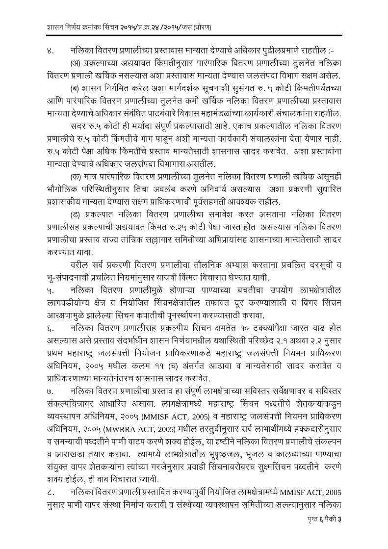
शािन लनणणय करमाकः सिचन 2015/पर.कर.24 /2015/जि (धोरण)
पषटठ 6 पकी 3
4. नलिका लितरण परणािीचया परसतािाि मानयता दणयाच अलधकार प ढीिपरमाण राहतीि :- (अ) परकयापाचया अदययाित सकमतीन िार पारपालरक लितरण परणािीचया त िनत नलिका
लितरण परणािी खरथचक नियायाि अशा परसतािाि मानयता दणयाि जििपदा लिभाग िकषम अिि. (ब) शािन लनगणलमत करि अशा मागणदशणक िचनाशी ि िगत र. 5 कोटी सकमतीपयतचया
आलण पारपालरक लितरण परणािीचया त िनत कमी खरथचक नलिका लितरण परणािीचया परसतािाि मानयता दणयाच अलधकार िबलधत पाटबधार लिकाि महामडळाचया कायणकारी िचािकाना राहतीि.
िदर र.5 कोटी ही मयादा िपणण परकयापािाठी आह. एकाच परकयापातीि नलिका लितरण परणािीच र.5 कोटी सकमतीच भाग पाडन अशी मानयता कायणकारी िचािकाना दता यणार नाही. र.5 कोटी पकषा अलधक सकमतीच परसताि मानयतिाठी शािनाि िादर कराित. अशा परसतािाना मानयता दणयाच अलधकार जििपदा लिभागाि अितीि.
(क) मातर पारपालरक लितरण परणािीचया त िनत नलिका लितरण परणािी खरथचक अिनही भौगोलिक पलरससथतीन िार लतचा अििब करण अलनिायण अियायाि अशा परकरणी ि धालरत परशािकीय मानयता दणयाि िकषम परालधकरणाची पिणिहमती आिशयक राहीि. (ड) परकयापात नलिका लितरण परणािीचा िमािश करत अिताना नलिका लितरण परणािीिह परकयापाची अदययाित सकमत र.25 कोटी पकषा जासत होत अियायाि नलिका लितरण परणािीचा परसताि राजय तालतरक िललागार िलमतीचया अलभपरायािह शािनाचया मानयतिाठी िादर करणयात यािा.
िरीि ििण परकरणी लितरण परणािीचा तौिलनक अभयाि करताना परचलित दरिची ि भ-िपादनाची परचलित लनयमान िार िाजिी सकमत लिचारात घणयात यािी. 5. नलिका लितरण परणािीम ळ होणाऱया पाणयाचया बचतीचा उपयोग िाभकषतरातीि िागिडीयोगय कषतर ि लनयोलजत सिचनकषतरातीि तफाित दर करणयािाठी ि लबगर सिचन आरकषणाम ळ झाियाया सिचन कपातीची पनसथापना करणयािाठी करािा. 6. नलिका लितरण परणािीिह परकयापीय सिचन कषमतत 10 टककयापकषा जासत िाढ होत अियायाि अि परसताि िदभाधीन शािन लनणणयामधीि यथाससथती पलरचछद 2.1 अथिा 2.2 न िार परथम महाराषटर जििपतती लनयोजन परालधकरणाकड महाराषटर जििपतती लनयमन परालधकरण अलधलनयम, 2005 मधीि किम 11 (च) अतगणत आढािा ि मानयतिाठी िादर कराित ि परालधकरणाचया मानयतनतरच शािनाि िादर कराित. 7. नलिका लितरण परणािीचा परसताि हा िपणण िाभकषतराचया िलिसतर ििकषणािर ि िलिसतर िकयापलचतरािर आधालरत अिािा. िाभकषतरामधय महाराषटर सिचन पधदतीच शतकऱयाकडन वयिसथापन अलधलनयम, 2005 (MMISF ACT, 2005) ि महाराषटर जििपतती लनयमन परालधकरण अलधलनयम, 2005 (MWRRA ACT, 2005) मधीि तरत दीन िार ििण िाभाथीमधय हककदारीन िार ि िमनयायी पधदतीन पाणी िाटप करण शकय होईि, या दषटटीन नलिका लितरण परणािीच िकयापन ि आराखडा तयार करािा. तयामधय िाभकषतरातीि भपषटठजि, भजि ि कािवयाचया पाणयाचा िय कत िापर शतकऱयाना तयाचया गरजन िार परिाही सिचनाबरोबरच ि कषमसिचन पधदतीन करण शकय होईि, ही बाब लिचारात घयािी. 8. नलिका लितरण परणािी परसतालित करणयाप िी लनयोलजत िाभकषतरामधय MMISF ACT, 2005
न िार पाणी िापर िसथा लनमाण करािी ि िसथचया वयिसथापन िलमतीचया ियायायान िार नलिका
30
शािन लनणणय करमाकः सिचन 2015/पर.कर.24 /2015/जि (धोरण)
पषटठ 6 पकी 4
लितरण परणािीचा आराखडा ि तयाच बाधकाम कराि. नलिका लितरण परणािीच काम पणण झायायािर वयिसथापनािाठी ि दखभाि द रसतीिाठी हसतातरीत करन घणयाची पाणी िापर िसथची िखी िहमती अलनिायण राहीि. तिच काम पणण झायायानतर लितरण परणािी वयिसथापनािाठी ि दखभाि द रसतीिाठी पाणी िापर िसथि हसतातरीत करािी. 9. नलिका लितरण परणािी धोरण महणन सिीकारताना लिभागाकड याबाबतच िकयापन करणारी सिततर यतरणा उपिब ध अिण गरजच आह. उपिबध आसथापनतन अशी यतरणा जििपदा लिभागान लनमाण करािी. 10. नलिकची उभारणी जलमनीखािी अशा खोिीिर करािी की नलिकचया माथयािर 1.2 मी. चा भराि राहीि, जणकरन शतीचया अिजाराम ळ नलिकि बाधा पोहोचणार नाही .
नलिका जोडणी लपक लनघन गयायानतर करणयाच लनयोजन कराि. यािाठी लपक न किान
भरपाईची तरतद कर नय. 11. नलिकाचा प रिठा ि जोडणी ि पलहयाया 3 िषािाठी दखभाि द रसतीचा अतभाि अिििी एकलतरत लनलिदा काढािी. फकत प रिठयािाठी दयक अदायगी कर नय. एका पाणी िापर िसथचया िपणण कायणकषतरातीि नलिका लितरणाच काम पणण झायायानतर अशत: अदायगी ि उिणलरत रककम टपया-टपयान यशसिी चाचणी ि Defect Liability Period िपयायािर करािी. यािाठी वयिहायण रककम रोखन ठिणयात यािी. Defect Liability Period 5 िष अिािा. तयापकी 3 िष दखभाि, द रसती ि सिचन वयिसथापनाची जबाबदारी ठकदारािर ठिािी. 12. नलिका लितरण परणािी बाबतच िलिसतर लनकष / मागणदशणक िचना जििपदा लिभागान तालतरक पलरपतरकावदार लनगणलमत करावयात. िदर शािन लनणणय लनयोजन लिभागान अनौपचालरक ि.कर.1/का.1434, लद.06.01.2016 ि लितत लिभागान अनौपचालरक ि.कर.32/2016,लद.04.02.2016 आलण महाराषटर जििपतती लनयमन परालधकरणान िदभण पतर कर.581, लद.30.09.2015 अनिय लदियाया िहमतीन लनगणलमत करणयात यत आह. िदर शािन लनणणय महाराषटर शािनाचया www.maharashtra.gov.in या िकतसथळािर उपिबध करन दणयात आिा अिन तयाचा िकताक कर. 201606091802024527 अिा आह. हा आदश लडजीटि सिाकषरीन िाकषालकत करन काढणयात यत आह. महाराषटराच राजयपाि याचया आदशान िार ि नािान.
( र.रा.श किा )
शािनाच उप िलचि परत, 1. मा.राजयपाि याच िलचि, राजभिन, म बई 2. मा.म खयमतरी याच परधान िलचि, मतरािय, म बई 3. मा.मतरी, जििपदा याच सिीय िहायक, मतरािय, म बई ४. मा.राजयमतरी, जििपदा याच सिीय िहायक, मतरािय, म बई
Rajnish Ramkishor Shukla
Digitally signed by Rajnish Ramkishor Shukla DN: c=IN, o=Government Of Maharashtra, ou=Water Resources, postalCode=400032, st=Maharashtra, 2.5.4.20=d37cbfb080a0bc996a710b3c0aeea737985dac09cb66bbff878f42ad4e77a606, serialNumber=293016b5f13cd03f75c9f34c66d956309c8b3cd5faf07931d817577e6116e436, cn=Rajnish Ramkishor Shukla Date: 2016.06.09 18:16:22 +05'30'
31
शािन लनणणय करमाकः सिचन 2015/पर.कर.24 /2015/जि (धोरण)
पषटठ 6 पकी 5
५. ििण लिधानिभा िदसय / लिधान पलरषद िदसय ६. मा.म खय िलचि, मतरािय, म बई. ७. परधान िलचि, िामानय परशािन लिभाग, मतरािय, म बई ८. परधान िलचि, लितत लिभाग, मतरािय, म बई ९. परधान िलचि, लनयोजन लिभाग, मतरािय, म बई १०. परधान िलचि (जि), जििपदा लिभाग, मतरािय, म बई ११. िलचि (िाकषलि), जििपदा लिभाग, मतरािय, म बई १२. िलचि, महाराषटर जििपतती लनयमन परालधकरण,म बई. १३. महािखापाि, महाराषटर, म बई / नागपर १४. महािचािक, मरी, नालशक १५. महािचािक, िायामी, औरगाबाद १६. कायणकारी िचािक, महाराषटर कषटणा खोर लिकाि महामडळ, प ण १७. कायणकारी िचािक, कोकण पाटबधार लिकाि महामडळ, ठाण १८. कायणकारी िचािक, तापी पाटबधार लिकाि महामडळ, जळगाि १९. कायणकारी िचािक, गोदािरी मराठिाडा पाटबधार लिकाि महामडळ, औरगाबाद २०. कायणकारी िचािक, लिदभण पाटबधार लिकाि महामडळ, नागपर २१. म खय अलभयता, जिलिजञान परकयाप, नालशक २२. म खय अलभयता, यालतरकी, जििपदा लिभाग, नालशक २३. म खय अलभयता, जिलिदयत परकयाप (लिदयत), म बई २4. म खय अलभयता, जििपदा लिभाग, औरगाबाद /नागपर /अमरािती / प ण / कोकण लिभाग / म बई / उततर महाराषटर लिभाग, नालशक / तापी पाटबधार लिभाग, जळगाि २5. म खय अलभयता, िाभकषतर लिकाि, औरगाबाद २6. म खय अलभयता, महाराषटर जि लिकाि क दर, औरगाबाद २7. म खय अलभयता, गोिीख दण परकयाप, जििपदा लिभाग, नागपर २8. म खय अलभयता (लि.पर.), जििपदा लिभाग, अमरािती 29. म खय अलभयता (लि.पर.), जििपदा लिभाग, प ण ३0. म खय अलभयता (द ि पर) ि िह िलचि, जििपदा लिभाग, मतरािय, म बई ३1. म खय अलभयता (पा) ि िह िलचि, जििपदा लिभाग, मतरािय, म बई ३2. म खय अलभयता (कपाति) ि िह िलचि, जििपदा लिभाग, मतरािय, म बई ३3. म खय अलभयता (जि) ि िह िलचि, जििपदा लिभाग, मतरािय, म बई. 34. म खय अलभयता, िकिन, परलशकषण, िशोधन ि ि रलकषतता, मरी, नालशक. 35. म खय अलभयता (सथापतय), जिलिदय त, प ण. 36. िह िलचि (ििा), जििपदा लिभाग, मतरािय, म बई ३7. आतरलितत िललागार ि िह िलचि, जििपदा लिभाग, मतरािय, म बई 38. अधीकषक अलभयता, पाटबधार िशोधन ि लिकाि िचािनािय, प ण 39. अधीकषक अलभयता, (माती धरण), मधयिती िकयापलचतर िघटना (िीडीओ), नालशक. 40. अधीकषक अलभयता, महाराषटर अलभयालतरकी िशोधन िसथा, नालशक.
32
शािन लनणणय करमाकः सिचन 2015/पर.कर.24 /2015/जि (धोरण)
पषटठ 6 पकी 6
41. अधीकषक अलभयता, (वदार), मधयिती िकयापलचतर िघटना (लिलडओ), नालशक. 42. अधीकषक अलभयता, (दगडी धरण), मधयिती िकयापलचतर िघटना (लिलडओ), नालशक. 43. अधीकषक अलभयता, (लिदय त गह), मधयिती िकयापलचतर िघटना (लिलडओ), नालशक. 44. कोयना िकयापलचतर मडळ, प ण. 45. कोयना (लि.ि.या) िकयापलचतर मडळ, प ण 46. महाराषटर अलभयालतरकी परलशकषण परबोलधनी, नालशक. 47. अधीकषक अलभयता, धरण ि रलकषतता िघटना, (DSO) नालशक. 48. जिलनयोजन लिभाग, मधयिती िकयापलचतर िघटना (लिलडओ), नालशक. 49. जिगती िशोधन लिभाग कर.1, नालशक 50. भ कप उपकरण ककष ि भ कप आधार िाम गरी पथ:करण ककष, नालशक. 51. िरचनातमक िशोधन ि पदाथण लिजञान लिभाग, नालशक. 52. अधीकषक अलभयता, ग ण लनयतरण मडळ, प ण 53. अधीकषक अलभयता, ग ण लनयतरण मडळ, नागपर. 54. अधीकषक अलभयता, ग ण लनयतरण मडळ, औरगाबाद. 55. गाळ ििकषण लिभाग, नालशक. 56. ि दर ििदन ि भमालहती शासतर लिभाग, नालशक. 57. िाम गरी चाचणी लिभाग ि मद चाचणी लिभाग, मरी, नालशक. 58. भ कप आधार िाम गरी पथ:करण लिभाग, मरी, नालशक. 59. उपकरण िशोधन लिभाग, मरी, नालशक 60. अधीकषक अलभयता, आधार िाम गरी (पथ:करण) मडळ,नालशक 61. ििण उप िलचि / अिर िलचि / ककष अलधकारी, जििपदा लिभाग, मतरािय, म बई. 62. जििपदा (धोरण) कायािन (िगरहाथण).
33
सिचन परकलपात नलिकवदार पाणयाच लितरण.
महाराषटर शािन जििपदा लिभाग
शािन लनणणय कर. सिचन 2015/पर.कर.24 /2015/जि (धोरण) मतरािय, म बई-400 032.
लदनाक :- 13 जानिारी, 2017.
िाचाि : 1) महाराषटर शािन, जििपदा लिभाग, शा.लन. कर. सिचन 2015/पर.कर.24 /2015/जि (धोरण), लदनाक 09 जन, 2016. 2) महाराषटर शािन, जििपदा लिभाग, शा.लन. कर. िकीणण 2015/(425/2015)/ मधयम परकलप,
लद. 16 नोवहबर, 2016.
परसतािना :- क दर शािनान िन 2017 पयत पाणी िापराचया कायणकषमतत 20 टककयानी िाढ करणयाच उलिषटट ठिि आह ि तया अन षगान उपाययोजना करणयाच राजय शािनाि आवहान किि आह. कषी कषतरातीि पाणी िापर हा िकषणीय अिलयान कषी कषतरातीि पाणी िापराची कायणकषमता िाढलिणयाि पराधानय दण गरजच आह. तिच महाराषटर जििपतती लनयमन परालधकरणाचया (MWRRA) लद. 12.6.2015 रोजीचया अलधिचनन िार िन 2019 पािन बारमाही लपकाना ि कषम सिचनादवार पाणी दण अलनिायण किि आह.
महाराषटर जि ि सिचन आयोगान अदालजत कलयान िार राजयाच िागिडीिायक कषतर ि मार 225 िकष हकटर आह. राजयातीि भपषटठािरीि ि भजिाची उपिबधता लिचारात घता भपषटठािरीि पाणयातन ि मार 85 िकष हकटर ि भजिावदार 41 िकष हकटर अि एकण 126 िकष हकटर महणजच िागिडीिायक कषतराचया 56 टकक इतकच कषतर अलतमत: सिचनाखािी यऊ शकत. िाढतया नागरीकरणाम ळ ि औदयोलगकरणाम ळ लबगर सिचन पाणी िापरात िाढ होत आह. तयाम ळ सिचनािाठी उपिबध होणाऱया पाणयात घट झािी आह ि ही घट भलिषटयात िाढतच जाणार आह. िदर िसत ससिती लिचारात घऊन सिचनािाठी उपिबध होणाऱया पाणयाचा इषटटतम िापर करन जासतीत जासत कषतर सिचनाखािी आणण गरजच आह. यािाठी पारपारीक लितरण परणािी ि सिचन पधदतीत ि धारणा करणयाची गरज लनमाण झािी आह.
पारपालरक लितरण परणािीत कािि, लितलरका, िघ कािि ि शतचाऱयाची आखणी कािवयाचया परिाहािाठी जमीनीची आिशयक पातळी लिचारात घऊनच करािी िागत. यामधय काही लिलशषटठ शतकऱयाची जासत जमीन जात.
कािि बाधािरन घयाित, ििाची जमीन िमपरमाणात घयािी, अशा िचना करन शतकरी लितरण परणािीि लिरोध करतात. शतकऱयाचा लिशषत: अलप भधारक शतकऱयाचा लिचार करता तयाची भलमका योगयही अित. मातर पारपालरक काििा लितरण परणािी िकसलपत करताना तालतरक अपलरहायणतम ळ या िचना मानय करता यत नाहीत. तयाम ळ शतकऱयाचा लिरोध कायम राहतो ि लितरण वयिसिची काम िषान िष रगाळतात.
कािवयाचया म खाकडीि शतकरी िट कािवयािर पप बििन पाणी घतात. तयाम ळ म खाकडीि भागात पाणयाचा जादा पाणी िापर होतो. मातर प चछ भागातीि शतकरी सिचनाचया िाभापािन िलचत राहतात. काही परकरणी उपरोकत कारणाम ळ लितरण वयिसिअभािी धरणात पाणीिाठा होऊनही तयाचा िापर होत नाही ि आरथिक ग तिणक फिदर प होत नाही. अशा परकरणी सिचनाच िाभ ििकर लमळणयािाठी नलिका लितरण हा एक पयाय होऊ शकतो.
गलया नलजकचया कािािधीत जलमनीचया सकमती मोठया परमाणािर िाढलया आहत.
34
शािन लनणणय करमाकः सिचन 2015/पर.कर.24 /2015/जि (धोरण)
पषटठ 6 पकी 2
भ-िपादनािह कािवयाच मातीकाम, बाधकाम लिचारात घऊन तयािरीि एकण भाडििी ग तिणकीचा ि आिती खचाचा एकलतरत लिचार कलयाि बऱयाच परकरणी नलिका लितरण आरथिकदषटटया लकफायतशीर ठर शकत. कोकणािारखया जासत चढउतार अिणाऱया िाभकषतरातीि लितरण परणािीिरीि बाधकामाची िखया जासत राहत. अशा पलरससितीत पाईप लितरण परणािीचा अििब कलयाि बाधकामाची िखया कमी होत ि खचात बचत होत. तयाचपरमाण काळया मातीतीि कािवयािरीि बाधकामाचा खचण खोि पायाम ळ जासत यतो. अशा परकरणी ि धदा नलिका लितरण परणािी लकफायतशीर ठर शकत.
तयाचपरमाण जलमनीत आिशयकतपकषा जासत ओिािा लनमाण झालयाि ितरा लपकाच ि फळ बागाचया उतपादनात घट होत. याउिट नलिका लितरण परणािीदवार आिशयकतन िार लनयलतरत पाणी प रिठा करता यत अिलयान लिशष करन ितरा ि इतर फळबागा अिणाऱया परकलप िाभकषतरात तिच पलिम लिदभातीि खारपाण पटटयात पारपालरक लितरण परणािीि शतकऱयाचा लिरोध आह. नलिका लितरण परणािीिाठी शतकरी आहही आहत.
नलिका परणािीम ळ भिपादनाची गरज राहत नाही. तिच मशागतीि कोणताही अडिळा यत नाही. नलिका लितरणादवार िमनयायी पाणयाच िाटप करणही ि िभ होत. नलिका लितरण परणािीचा दखभाि-द रसती ि पलरचिनाचा खचणही त िनन कमी राहतो. डोगर उतारािरीि, खोि खोदाईतीि ि काळया मातीतीि कािवयािर त िनन दखभाि-द रसतीचा खचण जासत राहतो.
िरीिपरमाण लिलिध सिालनक पलरससितीमधय नलिका लितरण ह पारपालरक काििा लितरणापकषा िरि ठर शकत. मातर शािनाचया अि लनदशणनाि आि आह की, महाराषटर शािन, जििपदा लिभाग, शािन लनणणय कर. मजलनपरा-2011/(24/2011)/जि (आसिा.), लद. 10 जन 2013 मधीि तरत दीन िार किळ परशािकीय मानयता परापत परकलप अहिािात पारपालरक लितरण परणािीची तरतद अिलयान ि धालरत परशािकीय मानयता घतलयालशिाय नलिका लितरण परणािीचा अििब करता यत नाही. तयाम ळ नलिका लितरण परणािी बाबत सिततर धोरण िदभण कर.1 यिीि लदनाक 09 ज न 2016 चया शािन लनणणयान िार जालहर करणयात आि. िदर नलिकवदार सिचन लितरण धोरणाचया अन षगान राजयािाठी नलिकावदार सिचन लितरण परणािीचया जिदपण ि कायणकषम अमिबजािणीिाठी ििण पाटबधार लिकाि महामडळाच कायणकारी िचािक, म खय अलभयता, अलधकषक अलभयता ि िबलधत कायणकारी अलभयता याची लदनाक 13 ज ि 2016 रोजी िालमी, औरगाबाद यि कायणशाळा घणयात आिी. िदर कायणशाळत क दर शािनाचया PMKSY योजन अतगणतच सिचन परकलप तिच भिपादनाचया अडचणीम ळ काही लठकाणी कािवयाची काम पणण न झालयाम ळ िप णण लितरण परणािीमधय ििगता नाही, अशा परकलपामधय नलिका लितरण परणािी जिदगतीन घणयािाठी लदनाक 09.06.2016 चया शािन लनणणयामधय काही ि धारणा करण आिशयक अिलयाबाबतचया लशफारशी करणयात आलया. पारपालरक लितरण परणािी ऐिजी नलिका लितरण परणािी अििबताना कािपवयय टाळन अमिबजािणी जिदगतीन होणयािाठी लदनाक 13.07.2016 रोजीचया कायणशाळतीि लशफारशीन िार लदनाक 09.06.2016 चया शािन लनणणयात बदि करण आिशयक आह. तिच दरमयानचया काळात िदभण 2 मधीि शािन लनणणय लनगणलमत झािा आह.
या पारशणभलमिर िदभण कर.1 यिीि लदनाक 09.06.2016 रोजीचा शािन लनणणय अलधकरलमत करणयात यत अिन शािनान प ढीिपरमाण लनणणय घतिा आह.
35
शािन लनणणय करमाकः सिचन 2015/पर.कर.24 /2015/जि (धोरण)
पषटठ 6 पकी 3
शािन लनणणय :- परशािकीय मानयता परापत परकलप अहिािात पारपालरक काििा लितरण वयिसिची तरतद अिताना
किळ योजनचया काही भागात नलिका लितरण परणािी परसतालित करताना िपणण परकलप अहिािाि ि धालरत परशािकीय मानयता घणयाची गरज राहणार नाही. मातर नलिका लितरणाचा परसताि शािन लनगणलमत करि अशा मागणदशणक िचनाशी ि िगत अिािा.
2. नलिका लितरण परणािी िापरणयािाठी शािन सतरािरन कोणतयाही सिततर मानयतची आिशयकता राहणार नाही. महाराषटर िािणजलनक बाधकाम लनयमाििी पलरचछद 134 ि 135 ि पलरलशषटठ-42, (महाराषटर शािन, िािणजलनक बाधकाम लिभाग, शािन लनणणय लिअि 2015/पर.कर.218/इमारती-2, लद.16 लडिबर 2015 न िार ि धालरत कलयापरमाण) न िार तालतरक मानयति म खय अलभयता याना पणण अलधकार, अधीकषक अलभयता याना र. 2.5 कोटी पयणनत ि कायणकारी अलभयता याना 1.0 कोटी पयत अलधकार आहत. याच मयादत िकलपलचतर मजरीच अलधकार िबलधत कषलतरय अलधकाऱयाना आहत. म खय अलभयता याना िकलपलचतर मानयतबाबत ही पणण अलधकार आहत. िदर परदान किलया अलधकाराचा िापर करन परकलपाचया / परकलप घटकाचया पाईप लितरण परणािीचया अदाजपतरकाि िकषम सतरािरन तालतरक मानयता दणयात यािी. ततप िी नलिका लितरण परणािीचा परसताि शािन लनगणलमत करि अशा मागणदशणक िचनाशी ि िगत आह याची खातरी करणयात यािी. तिच तालतरक मानयता दणयाि िकषम अलधकाऱयान नलिका लितरण आराखडयाि ि िकलपलचतराि मानयता दयािी. परसतािाची आरथिक वयिहायणता तपािन िबलधत कायणकारी िचािकानी परसतािाि मानयता दयािी.
3. नलिका लितरण परणािीचा परसताि हा आिशयक ििकषणािर ि िलिसतर िकलपलचतरािर आधालरत अिािा. िाभकषतरामधय महाराषटर सिचन पधदतीच शतकऱयाकडन वयिसिापन अलधलनयम, 2005 (MMISF ACT, 2005) ि महाराषटर जििपतती लनयमन परालधकरण अलधलनयम, 2005 (MWRRA ACT, 2005) मधीि तरत दीन िार ििण िाभािीमधय हककदारीन िार ि िमनयायी पधदतीन पाणी िाटप करण शकय होईि, या दषटटीन नलिका लितरण परणािीच िकलपन ि आराखडा तयार करािा. नलिका लितरण परणािी आराखडा तयार करताना िाभकषतरातीि भपषटठजि, भजि ि कािवयाचया पाणयाचा िय कत िापर शतकऱयाना तयाचया गरजन िार परिाही सिचनाबरोबरच ि कषमसिचन पधदतीन करण शकय होईि, ही बाब लिचारात घयािी.
4. नलिका लितरण परणािीम ळ होणाऱया पाणयाचया बचतीचा उपयोग िाभकषतरातीि िागिडीयोगय कषतर ि लनयोलजत सिचनकषतरातीि तफाित दर करणयािाठी ि लबगर सिचन आरकषणाम ळ झािलया सिचन कपातीची पनसिापना करणयािाठी करािा.
5. नलिका लितरण परणािीम ळ िदभण 2 मधीि शािन लनणणयातीि पलरचछद 2 न िार वयापती बदि होत अिलयाि या शािन लनणणयातीि नम द पलरचछद 4 न िार ि धालरत परशािकीय मानयता घणयाबाबतची कायणिाही करािी.
6. नलिका लितरण परणािी परसतालित करणयाप िी लनयोलजत िाभकषतरामधय MMISF ACT, 2005 न िार लनमाण कराियाचया पाणी िापर िसिाबाबतच लनयोजन ि आराखडा तयार करािा तिच लनयोजनामधय िाभधारकाचा िहभाग घणयात यािा. नलिका लितरण परणािीच काम ि र होईपयत महाराषटर सिचन परणािीच शतकऱयाकडन वयिसिापन अलधलनयम 2005 किम 1 (3) ि 2 ची अलधिचना काढणयात यािी. नलिका लितरण परणािीच काम िपपयत उकत अलधलनयमातीि किम 5, 6, 7 न िार अलधिचना 3 काढणयात यािी. काम पणण
36
शािन लनणणय करमाकः सिचन 2015/पर.कर.24 /2015/जि (धोरण)
पषटठ 6 पकी 4
झालयानतर ि पलहिी 3 िष पलरचिन झालयानतर लितरण परणािी वयिसिापनािाठी पाणीिापर िसिि हसतातरीत करािी.
7. नलिका जोडणी शकयतो लपक लनघन गलयानतर करणयाच लनयोजन कराि, मातर आिशयकतन िार लपक न किान भरपाईची तरतद करणयात यािी.
8. नलिका लितरण परणािी धोरण महणन सिीकारताना लिभागाकड याबाबतच िकलपन करणारी सिततर यतरणा उपिब ध अिण गरजच आह. उपिबध आसिापनतन अशी यतरणा जििपदा लिभागान लनमाण करािी ि ती दोन िषात िकषम करािी.
उपरोकत सिततर यतरणा िकषमतन कायणरत होईपयत िलिसतर िकलपनाची पयायी वयिसिा लिभागातगणत सकिा खाजगी िललागारामाफण त करणयात यािी तिच िकलपलचतरािह योजना कायानियीत करणयाबाबतचया लनलिदा काढणयाचा पयाय लनिडािा, मातर िबलधत म खय अलभयतयान िदर िकलपलचतराि मानयता दयािी.
9. लनलिदा मधीि दखभाि द रसती कािािधी 5 िष ठिणयात यािा. तयापकी शिटचया 2 िषात पाणी िापर िसििोबत ठकदारान िय कत कायणिाही करािी. एका पाणी िापर िसिचया िपणण कायणकषतरातीि नलिका लितरणाच काम पणण झालयानतर झािलया तया पाणीिापर िसिचया कायणकषतरातीि कामाचया पणण सकमतीचया 80% रककम अदा करािी ि उिणलरत रकमपकी 10% रककम यशसिी चाचणयानतर ि 10% रककम Defect Liability Period िाठी रोखन ठिणयात यािी. Defect Liability Period 5 िषाचा अिािा. Defect Liability िाठी राखन ठिििी 10% रककम Defect आढळलयाि त जया तया िळी कतराटदाराकडन दर करन घऊन दरिषी 2% परमाण अदा करािी, अि ििणिाधारणपण धोरण राहीि. तिालप अन भिाअती परकलपिापकष लिशषता लिचारात घऊन बदि करणयाच अलधकार म खय अलभयता याना राहतीि.
10. नलिका लितरण परणािी बाबतच िलिसतर लनकष / मागणदशणक िचना जििपदा लिभागान तालतरक पलरपतरकावदार लनगणलमत करावयात.
िदर शािन लनणणय िदभण - 2 मधीि शािन लनणणय अलधकरलमत करन तिच लनयोजन लिभागान अनौपचालरक ि.कर.163 /1433 /2016, लद.01.09.2016 ि लितत लिभागान अनौपचालरक ि.कर. 267/2016, लद. 23.11.2016 अनिय लदिलया िहमतीन लनगणलमत करणयात यत आह.
िदर शािन लनणणय महाराषटर शािनाचया www.maharashtra.gov.in या िकतसिळािर उपिबध करन दणयात आिा अिन तयाचा िकताक कर. 201701131701335427 अिा आह. हा आदश लडजीटि सिाकषरीन िाकषालकत करन काढणयात यत आह. महाराषटराच राजयपाि याचया आदशान िार ि नािान.
( र.रा.श किा ) शािनाच उप िलचि
परत, 1. मा.राजयपाि याच िलचि, राजभिन, म बई 2. मा.म खयमतरी याच परधान िलचि, मतरािय, म बई 3. मा.मतरी, जििपदा याच सिीय िहायक, मतरािय, म बई
Rajnish Ramkishor Shukla
Digitally signed by Rajnish Ramkishor Shukla DN: c=IN, o=Government Of Maharashtra, ou=Water Resources, postalCode=400032, st=Maharashtra, 2.5.4.20=d37cbfb080a0bc996a710b3c0aeea737985dac09cb66bbff878f42ad4e77a606, serialNumber=293016b5f13cd03f75c9f34c66d956309c8b3cd5faf07931d817577e6116e436, cn=Rajnish Ramkishor Shukla Date: 2017.01.13 17:15:47 +05'30'
37
शािन लनणणय करमाकः सिचन 2015/पर.कर.24 /2015/जि (धोरण)
पषटठ 6 पकी 5
4. मा.राजयमतरी, जििपदा याच सिीय िहायक, मतरािय, म बई 5. ििण लिधानिभा िदसय / लिधान पलरषद िदसय 6. मा.म खय िलचि, मतरािय, म बई. 7. परधान िलचि, िामानय परशािन लिभाग, मतरािय, म बई 8. परधान िलचि, लितत लिभाग, मतरािय, म बई 9. परधान िलचि, लनयोजन लिभाग, मतरािय, म बई 10. परधान िलचि (जि), जििपदा लिभाग, मतरािय, म बई 11. िलचि (िाकषलि), जििपदा लिभाग, मतरािय, म बई 12. िलचि (परि), जििपदा लिभाग, मतरािय, म बई 13. िलचि, महाराषटर जििपतती लनयमन परालधकरण,म बई. 14. महािखापाि, महाराषटर, म बई / नागपर 15. महािचािक, मरी, नालशक 16. महािचािक, िालमी, औरगाबाद 17. कायणकारी िचािक, महाराषटर कषटणा खोर लिकाि महामडळ, प ण 18. कायणकारी िचािक, कोकण पाटबधार लिकाि महामडळ, ठाण 19. कायणकारी िचािक, तापी पाटबधार लिकाि महामडळ, जळगाि 20. कायणकारी िचािक, गोदािरी मराठिाडा पाटबधार लिकाि महामडळ, औरगाबाद 21. कायणकारी िचािक, लिदभण पाटबधार लिकाि महामडळ, नागपर 22. म खय अलभयता, जिलिजञान परकलप, नालशक 23. म खय अलभयता, यालतरकी, जििपदा लिभाग, नालशक 24. म खय अलभयता, जिलिदयत परकलप (लिदयत), म बई 25. म खय अलभयता, जििपदा लिभाग, औरगाबाद /नागपर /अमरािती / प ण / कोकण लिभाग /
म बई / उततर महाराषटर लिभाग, नालशक / तापी पाटबधार लिभाग, जळगाि 26. म खय अलभयता, िाभकषतर लिकाि, औरगाबाद 27. म खय अलभयता, महाराषटर जि लिकाि क दर, औरगाबाद 28. म खय अलभयता, गोिीख दण परकलप, जििपदा लिभाग, नागपर 29. म खय अलभयता (लि.पर.), जििपदा लिभाग, अमरािती 30. म खय अलभयता (लि.पर.), जििपदा लिभाग, प ण 31. म खय अलभयता (द ि पर) ि िह िलचि, जििपदा लिभाग, मतरािय, म बई 32. म खय अलभयता (पा) ि िह िलचि, जििपदा लिभाग, मतरािय, म बई 33. म खय अलभयता (कपाति) ि िह िलचि, जििपदा लिभाग, मतरािय, म बई 34. म खय अलभयता (जि) ि िह िलचि, जििपदा लिभाग, मतरािय, म बई. 35. म खय अलभयता, िकिन, परलशकषण, िशोधन ि ि रलकषतता, मरी, नालशक. 36. म खय अलभयता (सिापतय), जिलिदय त, प ण. 37. िह िलचि (ििा), जििपदा लिभाग, मतरािय, म बई 38. आतरलितत िललागार ि िह िलचि, जििपदा लिभाग, मतरािय, म बई 39. अधीकषक अलभयता, पाटबधार िशोधन ि लिकाि िचािनािय, प ण
38
शािन लनणणय करमाकः सिचन 2015/पर.कर.24 /2015/जि (धोरण)
पषटठ 6 पकी 6
40. अधीकषक अलभयता, (माती धरण), मधयिती िकलपलचतर िघटना (िीडीओ), नालशक. 41. अधीकषक अलभयता, महाराषटर अलभयालतरकी िशोधन िसिा, नालशक. 42. अधीकषक अलभयता, (वदार), मधयिती िकलपलचतर िघटना (लिलडओ), नालशक. 43. अधीकषक अलभयता, (दगडी धरण), मधयिती िकलपलचतर िघटना (लिलडओ), नालशक.
44. अधीकषक अलभयता, (लिदय त गह), मधयिती िकलपलचतर िघटना (लिलडओ), नालशक. 45. कोयना िकलपलचतर मडळ, प ण. 46. कोयना (लि.ि.या) िकलपलचतर मडळ, प ण
47. महाराषटर अलभयालतरकी परलशकषण परबोलधनी, नालशक. 48. अधीकषक अलभयता, धरण ि रलकषतता िघटना, (DSO) नालशक. 49. जिलनयोजन लिभाग, मधयिती िकलपलचतर िघटना (लिलडओ), नालशक. 50. जिगती िशोधन लिभाग कर.1, नालशक 51. भ कप उपकरण ककष ि भ कप आधार िाम ही पि:करण ककष, नालशक. 52. िरचनातमक िशोधन ि पदािण लिजञान लिभाग, नालशक. 53. अधीकषक अलभयता, ग ण लनयतरण मडळ, प ण.
54. अधीकषक अलभयता, ग ण लनयतरण मडळ, नागपर. 55. अधीकषक अलभयता, ग ण लनयतरण मडळ, औरगाबाद. 56. गाळ ििकषण लिभाग, नालशक. 57. ि दर ििदन ि भमालहती शासतर लिभाग, नालशक. 58. िाम ही चाचणी लिभाग ि मद चाचणी लिभाग, मरी, नालशक. 59. भ कप आधार िाम ही पि:करण लिभाग, मरी, नालशक. 60. उपकरण िशोधन लिभाग, मरी, नालशक 61. अधीकषक अलभयता, आधार िाम ही (पि:करण) मडळ,नालशक 62. ििण उप िलचि / अिर िलचि / ककष अलधकारी, जििपदा लिभाग, मतरािय, म बई. 63. जििपदा (धोरण) कायािन (िहहािण).
39
सिचन परकलपात नलिकवदार पाणयाच लितरण
महाराषटर शािन जििपदा लिभाग
शािन लनणणय कर. सिचन 2015/पर.कर.24 /2015/जि (धोरण) मतरािय, म बई-400 032.
लदनाक :- 18 जानिारी, 2017.
िदभण : महाराषटर शािन, जििपदा लिभाग, शा.लन. कर. सिचन 2015/पर.कर.24 /2015/ जि (धोरण), लदनाक 13 जानिारी, 2017.
शािन श धदीपतरक :-
िदभालधन शािन लनणणयातीि प.कर.4 िरीि पलरचछद 10 नतरचा पलरचछद “ िदर शािन लनणणय िदभण - 2 मधीि शािन लनणणय अलधकरलमत करन तिच लनयोजन लिभागान अनौपचालरक ि.कर.163 / 1433 /2016, लद.01.09.2016 ि लितत लिभागान अनौपचालरक ि.कर. 267/2016, लद. 23.11.2016 अनिय लदिलया िहमतीन लनगणलमत करणयात यत आह.”
या िाकयाऐिजी
“ िदर शािन लनणणय िदभण - 1 मधीि शािन लनणणय अलधकरलमत करन तिच लनयोजन लिभागान अनौपचालरक ि.कर.163 / 1433 /2016, लद.25.10.2016 ि लितत लिभागान अनौपचालरक ि.कर. 267/2016, लद. 23.11.2016 अनिय लदिलया िहमतीन लनगणलमत करणयात यत आह.”
अि िाचाि. िदर शािन श धदीपतरक महाराषटर शािनाचया www.maharashtra.gov.in या िकतसथळािर उपिबध करन दणयात आिा अिन तयाचा िकताक कर. 201701181652217127 अिा आह. हा आदश लिजीटि सिाकषरीन िाकषालकत करन काढणयात यत आह. महाराषटराच राजयपाि याच आदशान िार ि नािान.
( र.रा.श किा ) शािनाच उप िलचि
परत, 1. मा.राजयपाि याच िलचि, राजभिन, म बई 2. मा.म खयमतरी याच परधान िलचि, मतरािय, म बई 3. मा.मतरी, जििपदा याच सिीय िहायक, मतरािय, म बई 4. मा.राजयमतरी, जििपदा याच सिीय िहायक, मतरािय, म बई 5. ििण लिधानिभा िदसय / लिधान पलरषद िदसय 6. मा.म खय िलचि, मतरािय, म बई. 7. परधान िलचि, िामानय परशािन लिभाग, मतरािय, म बई 8. परधान िलचि, लितत लिभाग, मतरािय, म बई 9. परधान िलचि, लनयोजन लिभाग, मतरािय, म बई 10. परधान िलचि (जि), जििपदा लिभाग, मतरािय, म बई 11. िलचि (िाकषलि), जििपदा लिभाग, मतरािय, म बई 12. िलचि (परि), जििपदा लिभाग, मतरािय, म बई
Rajnish Ramkishor Shukla
Digitally signed by Rajnish Ramkishor Shukla DN: c=IN, o=Government Of Maharashtra, ou=Water Resources, postalCode=400032, st=Maharashtra, 2.5.4.20=d37cbfb080a0bc996a710b3c0aeea737985dac09cb66bbff878f42ad4e77a606, serialNumber=293016b5f13cd03f75c9f34c66d956309c8b3cd5faf07931d817577e6116e436, cn=Rajnish Ramkishor Shukla Date: 2017.01.18 16:57:48 +05'30'
40
शािन श धदीपतरक करमाकः सिचन 2015/पर.कर.24 /2015/जि (धोरण)
पषटठ 3 पकी 2
13. िलचि, महाराषटर जििपतती लनयमन परालधकरण,म बई. 14. महािखापाि, महाराषटर, म बई / नागपर 15. महािचािक, मरी, नालशक 16. महािचािक, िालमी, औरगाबाद 17. कायणकारी िचािक, महाराषटर कषटणा खोर लिकाि महामिळ, प ण 18. कायणकारी िचािक, कोकण पाटबधार लिकाि महामिळ, ठाण 19. कायणकारी िचािक, तापी पाटबधार लिकाि महामिळ, जळगाि 20. कायणकारी िचािक, गोदािरी मराठिािा पाटबधार लिकाि महामिळ, औरगाबाद 21. कायणकारी िचािक, लिदभण पाटबधार लिकाि महामिळ, नागपर 22. म खय अलभयता, जिलिजञान परकलप, नालशक 23. म खय अलभयता, यालतरकी, जििपदा लिभाग, नालशक 24. म खय अलभयता, जिलिदयत परकलप (लिदयत), म बई 25. म खय अलभयता, जििपदा लिभाग, औरगाबाद /नागपर /अमरािती / प ण / कोकण लिभाग /
म बई / उततर महाराषटर लिभाग, नालशक / तापी पाटबधार लिभाग, जळगाि 26. म खय अलभयता, िाभकषतर लिकाि, औरगाबाद 27. म खय अलभयता, महाराषटर जि लिकाि क दर, औरगाबाद 28. म खय अलभयता, गोिीख दण परकलप, जििपदा लिभाग, नागपर 29. म खय अलभयता (लि.पर.), जििपदा लिभाग, अमरािती 30. म खय अलभयता (लि.पर.), जििपदा लिभाग, प ण 31. म खय अलभयता (द ि पर) ि िह िलचि, जििपदा लिभाग, मतरािय, म बई 32. म खय अलभयता (पा) ि िह िलचि, जििपदा लिभाग, मतरािय, म बई 33. म खय अलभयता (कपाति) ि िह िलचि, जििपदा लिभाग, मतरािय, म बई 34. म खय अलभयता (जि) ि िह िलचि, जििपदा लिभाग, मतरािय, म बई. 35. म खय अलभयता, िकिन, परलशकषण, िशोधन ि ि रलकषतता, मरी, नालशक. 36. म खय अलभयता (सथापतय), जिलिदय त, प ण. 37. िह िलचि (ििा), जििपदा लिभाग, मतरािय, म बई 38. आतरलितत िललागार ि िह िलचि, जििपदा लिभाग, मतरािय, म बई 39. अधीकषक अलभयता, पाटबधार िशोधन ि लिकाि िचािनािय, प ण 40. अधीकषक अलभयता, (माती धरण), मधयिती िकलपलचतर िघटना (िीिीओ), नालशक. 41. अधीकषक अलभयता, महाराषटर अलभयालतरकी िशोधन िसथा, नालशक. 42. अधीकषक अलभयता, (वदार), मधयिती िकलपलचतर िघटना (लिलिओ), नालशक. 43. अधीकषक अलभयता, (दगिी धरण), मधयिती िकलपलचतर िघटना (लिलिओ), नालशक. 44. अधीकषक अलभयता, (लिदय त गह), मधयिती िकलपलचतर िघटना (लिलिओ), नालशक. 45. कोयना िकलपलचतर मिळ, प ण. 46. कोयना (लि.ि.या) िकलपलचतर मिळ, प ण 47. महाराषटर अलभयालतरकी परलशकषण परबोलधनी, नालशक. 48. अधीकषक अलभयता, धरण ि रलकषतता िघटना, (DSO) नालशक. 49. जिलनयोजन लिभाग, मधयिती िकलपलचतर िघटना (लिलिओ), नालशक. 50. जिगती िशोधन लिभाग कर.1, नालशक 51. भ कप उपकरण ककष ि भ कप आधार िाम गरी पथ:करण ककष, नालशक.
41
शािन श धदीपतरक करमाकः सिचन 2015/पर.कर.24 /2015/जि (धोरण)
पषटठ 3 पकी 3
52. िरचनातमक िशोधन ि पदाथण लिजञान लिभाग, नालशक. 53. अधीकषक अलभयता, ग ण लनयतरण मिळ, प ण. 54. अधीकषक अलभयता, ग ण लनयतरण मिळ, नागपर. 55. अधीकषक अलभयता, ग ण लनयतरण मिळ, औरगाबाद. 56. गाळ ििकषण लिभाग, नालशक. 57. ि दर ििदन ि भमालहती शासतर लिभाग, नालशक. 58. िाम गरी चाचणी लिभाग ि मद चाचणी लिभाग, मरी, नालशक. 59. भ कप आधार िाम गरी पथ:करण लिभाग, मरी, नालशक. 60. उपकरण िशोधन लिभाग, मरी, नालशक 61. अधीकषक अलभयता, आधार िाम गरी (पथ:करण) मिळ,नालशक 62. ििण उप िलचि / अिर िलचि / ककष अलधकारी, जििपदा लिभाग, मतरािय, म बई. 63. जििपदा (धोरण) कायािन (िगरहाथण).
42
नलिकवदार लितरण परणािी धोरणाबाबत मारगदरगक सचना.
महाराषटर रासन जिसपदा लिभार
रासन पलरपतरक कर. ससचन 2015/पर.कर.24 /(भार-2)/2015/जस (धोरण) मतरािय, म बई-400 032.
लदनाक :- 02 फबर िारी, 2017.
िाचाि : रासन लनणगय कर. ससचन 2015/पर.कर.24 /2015/जस (धोरण), लदनाक 13 जानिारी, 2017 ि लदनाक 18 जानिारी, 2017.
परसतािना :- उपिबध पाणयाचा रतीसाठी इषटटतम िापर करणयाच रासनाच धोरण आह. तयाम ळ स कषम
ससचनास पराधानय आह. सदभीय रासन लनणगयावदार लनलित किि धोरण ह नलिकावदार लितरण परणािीच आह. यामधय लिचारात घतििी नलिका लितरण परणािी ही Pressurized असिी तरीही पाणयाचा दाब हा र रतिाकरगणीय उजवदार अलभपरत आह. लिमोचका खािीि नलिकवदार स कषम ससचनाच धोरणाची आखणी सिततरलरतया करणयात यणार आह. यासाठी लिदय त सकिा लिझि पपावदार बाहय उजचा िापर अलनिायग आह. ततप िी िाभकषतरात लिक लित साठ लनम ण करणयाच धोरण लनलित होण ररजच आह. ही परलकरया सदया रासनाचया लिचाराधीन आह.
लितरण परणािी ि ससचन परणािी या दोन लभनन बाबी आहत. लितरण परणािीवदार धरणातीि जिारयातीि / नदीतीि पाणी, पाणीिापर ससथचया कायगकषतरापयत पोहचिण अलभपरत आह. ह लितरण project specific / canal specific बाधकामाची ससथती (construction stage), भसपादनाची सदय: ससथती, भसतर, भौरोिीक ससथती, लपकरचना लिचारात घऊन परिाही कािि, नलिका सकिा दोनहीच लमशरण( Combination of both) िापरन करण अलभपरत आह. पारपालरक पाटचाऱया वदार ( flow irrigation पधदतीन ), त रार सकिा सठबक अस ससचनाच िरिरळ परकार आहत. ह पाणी िापर ससथचया कायगकषतरात काय सनित कराियाच आहत.
नलिका लितरण ससिकारि तरीही ससचनाची कोणतीही पधदत अििबता यत. मातर राजयातीि उपिबध पाणी ि िारििी िायक कषतर लिचारात घता सप णग िाभकषतरात स कषम ससचन ह जिसपदा लिभाराच दररामी (Long-term) उददीषटट राहीि. ह साधय करणच दषटटीन लितरण वयिसथा लनम ण करण सकिा सदयाची लितरण वयिसथा स कषम ससचनास प रक अरी रपातरीत करण आिशयक आह.
नलिकावदार ससचन लितरण धोरणाबाबतचा रासन लनणगय करमाक ससचन 2015/पर.कर.24 / 2015/जस (धोरण), लदनाक 13 जानिारी, 2017 रोजी लनरगलमत करणयात आिा आह. सदर रासन लनणगयाचया पलरचछद करमाक 10 अनिय नलिका लितरण परणािीबाबतच सलिसतर लनकर / मारगदरगक सचना जिसपदा लिभारान तालतरक पलरपतरकावदार लनरगलमत करावयात, अस सलचत करणयात आि आह.
43
रासन पलरपतरक करमाकः ससचन 2015/पर.कर.24 /(भार-2)/2015/जस (धोरण)
पषठ 11 पकी 2
तयाम ळ नलिका लितरण परणािीबाबतच सलिसतर लनकर / मारगदरगक सचना तयार करणयाच रासनाचया लिचाराधीन होत. सदर रासन लनणगयात नम द कलयान सार नलिका लितरण धोरणाचया अमिबजािणीसाठी सलिसतर लनकर / मारगदरगक सचना खािीिपरमाण आहत.
लनकर / मारगदरगक सचना :- ससचन परकलपाचया लितरण वयिसथत सपणग अथिा अरत: नलिका लितरण परणािीचा अििब
करणयासाठी खािीि लनकर / मारगदरगक सचना लिचारात घयावयात.
1.0 नलिकवदार लितरणाचा पय य लनििताना तया मारचा उददर सपषटट असािा. खािीिपकी कोणतया कषलतरय पलरससथतीत नलिका लितरणाचा पय य लनििणयात यत आह. तयाम ळ कोणत िाभ अपलकषत आहत, याचा सलिसतर परामरग घऊन तया बाबतची सियसपषटट नदद तालतरक मानयता परसतािात करािी. (1.1) िाभकषतरातीि जमीनीचा उतार तीवर असलयास कािवयािर /लितलरकिर / िघ
कािवयािर उपिबध अलतलरकत उजचा वयय करणयासाठी धबधबयाची (Series of Fall Structures) शररखिा बाधािी िारत . अरा पलरससथतीत उपिबध उजचा वयय / नार करणयासाठी धबधब बाधणीिर खचग करणयापकषा या उजचा िापर करन त िनन कमी खच त नलिका लितरण परणािी सकसलपत करणयास िाि असतो. सिगसाधारणपण जलमनीचा उतार 1:500 पकषा तीवर असलयास र रतिाकरगणानिय उजवदार नलिका लितरण वयिहायग ठरत.
(1.2) तयाचपरमाण िाभकषतरातीि जलमनीस मोठया परमाणािर चढ-उतार असलयास काििा बाधकामाचा खचग िाढतो. तसच रतचाऱयािरीि धबधबयाचा खचग िाढतो .अरा परकरणीही बदीसत नलिका लितरण वयिहायग ठर रकत.
(1.3) सतरा ि अनय फळबारासाठी तसच पलिम लिदभ तीि खारपाण पटटयात अतयत लनयलतरत ससचनाची ररज आह. जासत पाणयाम ळ फळबाराची उतपादकता (Productivity) कमी होत. अरा िाभकषतरासाठी बलदसत नलिका लितरण परणािीचा पय य अनय लनकराचया आधार तपासन सिीकारता यईि.
(1.4) निीन परकलपाचया बाबतीत जया परकरणी पारपालरक काििा लितरण परणािी भ-सपादनाचया खच म ळ अलधक महार ठरत , अरा परकरणी अनय अलभयालतरकी लनकरान सार नलिका लितरण तालतरक ि आरथथकदषटटया वयिहायग ठरत असलयास अरा लठकाणीही नलिका लितरण वयिसथा सिीकारता यईि.
(1.5) नलिका लितरणाम ळ िहनवययाची बचत होत. पाणी िापराची कायगकषमता िाढत. तयाम ळ उपसा ससचन योजनमधीि रीरगकामाचया भािििी र तिण कीत तसच िीज दयकाचया
44
रासन पलरपतरक करमाकः ससचन 2015/पर.कर.24 /(भार-2)/2015/जस (धोरण)
पषठ 11 पकी 3
आिती खच त बचत सभित. तयाम ळ निीन उपसा ससचन योजनामधय सकलपनाचया टपयािरच बलदसत नलिका लितरणाचा ि पारपालरक काििा लितरण परणािीचा तौिलनक अभयास करन परकलप अहिािामधय तरतदी करावयात ि तयान सार लितरण परणािीसाठीचया भ- सपादनाची तरतद करािी.
(1.6) काळया मातीचया िाभकषतरात पाया खोि असलयान कािवयािरीि बाधकामाचा भािििी खचग जासत यतो. तसच म रम जिळपास उपिबध नसलयास म रम िादी भरािासह (CNS Bedding) सधानकातीि असतरीकरणाचया त िनत नलिका लितरण लकफायतरीर ठर रकत .अरा परदरात तालतरक लनकरान सार नलिका लितरण परणािी सिीकारता यईि.
(1.7) जया लितरण परणािीचया बाबतीत स रिातीचया काही भारातीि भधारकाचया लिरोधाम ळ ससचनाच िाभ लमळणयास अिचण झािी असि, अरा परकरणी लितरण वयिसथची सिरता लनम ण करन (Bridging the gaps in the distribution system) ससचनाच िाभ स र करणयाचया दषटटीन लितरण परणािीच अरत: बाधकाम नलिका लितरणादवार करता यईि.
(1.8) बलदसत नलिका लितरणाम ळ पाणी बचत होत. या बचतीतन उपिबध पाणयातन जासतीच ससचन कषतर लनम ण होऊ रकत. तयाम ळ पणग झािलया परकलपातीि ससचनासाठी लनयोलजत किि पाणी लबरर ससचन परयोजनाथग िरग झाि असलयास, अरा परकरणी जवहा लितरण परणािीचया प न:सथ पनच काम लिचाराधीन असि तवहा, कपात किलया ससचनकषतराची प न:सथ पना करणयासाठी नलिका लितरणाचा पय य अनय अलभयालतरकी ि आरथथक लनकराचया चौकटीत तपासन सिीकारता यईि.
(1.9) राजयातीि ससचन परकलपाच िाभकषतर ठरलिताना िारििीयोगय कषतर (CCA) ि लनयोलजत ससचनकषतर (ICA) या दोन सजञा लिचारात घतलया जातात. सिगसाधारणपण ICA हा CCA चया 70 त 80 टकक असतो. तयाम ळ उपिबध पाणयाचया त िनत परतयकषात िाभकषतरात िारििीिायक कषतर जासत असत. या जासतीचया कषतरास पाणी घणयास रतकऱयाना परलतबध करण रकय नसत .तसच जिारयािरन ि कािवयािरन अन जञय मय दत लदलया जाणाऱया खाजरी उपसा कषतराची तरतद परकलप सकलपनात कििी नसत. तयाचपरमाण िाढतया नाररीकरणाम ळ ि औदयोलरकरणाम ळ परकलपीय तरतदीचया त िनत जासतीच पाणी लबररससचन परयोजनाथग िळोिळी िरग कि जात. तयाम ळ राजयातीि बह तक परकलपाचया जिलनयोजनािर ि ससचन वयिसथिर मोठया परमाणािर ताण लनम ण
45
रासन पलरपतरक करमाकः ससचन 2015/पर.कर.24 /(भार-2)/2015/जस (धोरण)
पषठ 11 पकी 4
झािा आह .नलिका लितरणाम ळ बचत झािलया पाणयातन मळ घोलरत िाभकषतरात लनम ण झाििी तट भरन काढण आलण CCA ि ICA मधीि तफाित दर करण हा उददर असािा. मातर नलिका लितरण परसतालित करन पाणी बचत दरगिन परकलपाचया मजर िाभकषतराबाहरीि िाढीि ससचनकषतर रासन पिगमानयतखरीज परसतालित कर नय.
2.00 सिगसाधारणपण मोठया ि मधयम परकलपामधय लितरीका / िघ लितरीका साठी ि िघ परकलपामधय सप णग लितरण वयिसथसाठी नलिका लितरणाचा अििब करािा.
3.00 जया परकरणी स कषम ससचनाचा भलिषटयात अििब करण परसतालित आह. अरा लठकाणी िघ कािवयाच लिमोचकाच खािी नलिका लितरण परणािी कायासनित कर नय. जिारय त िघ कािवयाचया म खापयतच नलिका लितरण मयालदत कराि. लिमोचका खािीि / लिक लित पाणी साठयाखािीि स कषम ससचन परणािी कर री लिभाराच अथगसाहाययाच मदतीन िाभाथीचया पाणीिापर ससथन करण अलभपरत आह.
4.00 भसपदानाचा खचग धरन नलिका लितरण वयिसथा पारपालरक काििा लितरणापकषा अलधक खरथचक ठरत. तयाम ळ जया परकरणी पारपालरक लितरण परणािी ररहीत धरन भ-सपादन झाि आह, अरा लठकाणी नलिका लितरणाचा लिचार कर नय.
5.00 नलिकाची लनिि :
सकसलपत लिसरग, तयासाठी िारणारा नलिकाचा वयास, पाणयाचा दाब, नलिकाचया परकारान सार अपलकषत आय षटयमान ि लटकाऊपणा, सकमत, हाताळणीतीि स िभता/अिचणी, जोिाईची स िभता, जोिाचा लटकाऊपणा, अनय फायद, तोट ि पिगअन भि लिचारात घऊन नलिकाचा परकार समजसपण (Judiciously) लनििणयाच सिाततरय म खय अलभयता याना राहीि.
6.00 जिरासतरीय सकलपन : (6.1) परकलपीय पीक रचनन सार पधरिियातीि जासतीत जासत पाणी ररज लिचारात घऊन
लितरण परणािीच सकलपन कराि. (6.2) Field Application Efficiency 75 टकक ि िहनवयय 5 टकक लिचारात घयािा. (6.3) पधरिियातीि 12 लदिस म खय िालहनी परिाही राहीि अस ररहीत धराि. लिमोचक 24
तास चाितीि अस ररहीत धराि. मातर अससततिात असिलया लितरण परणािीच scheduling िरळ असलयास तया scheduling री मळ बसि अस लकफायतरीर जिरासतरीय सकलपन कराि.
46
रासन पलरपतरक करमाकः ससचन 2015/पर.कर.24 /(भार-2)/2015/जस (धोरण)
पषठ 11 पकी 5
7.00 जििालहनयाच आरखन (Pipe Layout) : (7.1) नलिका लितरण परणािीच लनयोजनात “चक” च लनयोजन हा महतिाचा घटक आह.
सिकषणाअती सिगसाधारणपण 5 त 12 हकटर आकाराच चक लनयोजन कराि. मातर परकलप सापकष यात बदि करता यईि.
(7.2) Nearly equitable water distribution to all outlets and optimum cost ही दोन उददीषटट ठऊन Network architecture अलतम कराि.
(7.3) सिगसाधारण रचनमधय म खय िालहनी ही कमीत कमी िाबीची असािी. (7.4) म खय िालहनी परमाणच उपिालहनयाची आखणी करताना कमीत कमी िाबीत जासतीत
जासत िाभकषतरास िाभ दता यईि हा लनकर ठिािा. परतयक चक साठी सिततर उपिालहनी (Lateral) असािी. चक चा size ि shape लिचारात घऊन आिशयकतन सार sub-lateral परसतालित कराित.
(7.5) Operational Scheduling ह आरथथकदषटटया लकफायतरीर ि ससचन वयिसथापनाचया दषटटीन स टस टीत असाि.
Layout ि Operational Scheduling बाबत designer न तयाच कौरलय िापरण अलभपरत आह ि याबाबतची खातरजमा म खय अलभयता यानी मानयता दताना करण अलभपरत आह.
8.00 सकलपनाबाबत इतर मारगदरगक सचना : (8.1) परिाहाचा िर :- नलिकमधीि परिाहाचा िर कमी रालहलयास नलिकमधय राळ साठणयाचा
सभि असतो. तयाम ळ सपणग लितरण परणािीमधय परिाहाचा िर सिगसाधारणपण 1 मी./सकद इतका असािा. (0.8 मी./सकद त 1.2 मी./सकद) अपिादातमक पलरससथतीत कमी िाबीत परिाहाचा िर 0.6 मी./सकद पयत ससिकारता यईि. मातर परिाहाचा िर 0.6 मी./सकद पकषा क ठही कमी नसािा. तसच परिाहाचा िर 1.5 मी./सकद पकषा जासत नसािा. मातर नलिका िालहनी िोखिी, पीएससी सकिा एचिीपीई नलिकाची परसतालित असलयास खच तीि बचतीसाठी परिाहाची कमाि मय दा 1.8 मी./सकद पयत िाढिता यईि. मातर अस करताना नलिका रटीर लकमान 4 kg/cm2 इतक असाि. जया िाबीत परिाहाचा िर 0.6 मी./स. पकषा कमी राहणयाची रकयता आह तया िाबीत Scouring arrangement परसतालित करािी.
(8.2) नलिका लितरण परणािीच सकलपन करताना नलिकचा वयास असा असािा लक नलिका वदार सकसलपत लिसरग राशवतपण उपिबध होईि. नलिकचा वयास ररजपकषा कमी रालहलयास सबलधत कषतरास प रसा पाणी प रिठा होत नाही याउिट नलिकचा वयास
47
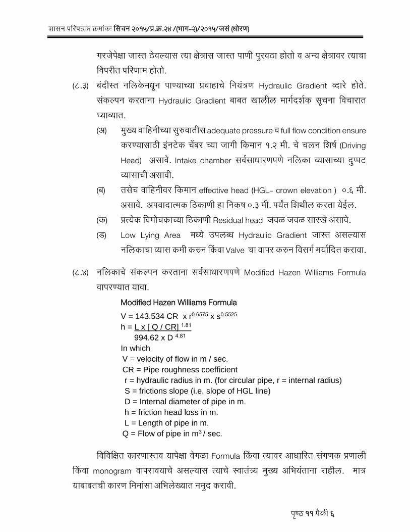
रासन पलरपतरक करमाकः ससचन 2015/पर.कर.24 /(भार-2)/2015/जस (धोरण)
पषठ 11 पकी 6
ररजपकषा जासत ठिलयास तया कषतरास जासत पाणी प रिठा होतो ि अनय कषतरािर तयाचा लिपरीत पलरणाम होतो.
(8.3) बदीसत नलिकमधन पाणयाचया परिाहाच लनयतरण Hydraulic Gradient वदार होत. सकलपन करताना Hydraulic Gradient बाबत खािीि मारगदरगक सचना लिचारात घयावयात. (अ) म खय िालहनीचया स रिातीस adequate pressure ि full flow condition ensure
करणयासाठी इनटक चबर चया जारी लकमान 1.2 मी. च चिन लररग (Driving Head) असाि. Intake chamber सिगसाधारणपण नलिका वयासाचया द पपट वयासाची असािी.
(ब) तसच िालहनीिर लकमान effective head (HGL- crown elevation ) 0.6 मी. असाि. अपिादातमक लठकाणी हा लनकर 0.3 मी. पयत लरथीि करता यईि.
(क) परतयक लिमोचकाचया लठकाणी Residual head जिळ जिळ सारख असाि. (ि) Low Lying Area मधय उपिबध Hydraulic Gradient जासत असलयास
नलिकाचा वयास कमी करन सकिा Valve चा िापर करन लिसरग मय लदत करािा.
(8.4) नलिकाच सकलपन करताना सिगसाधारणपण Modified Hazen Williams Formula िापरणयात यािा.
Modified Hazen Williams Formula V = 143.534 CR x r0.6575 x s0.5525
h = L x [ Q / CR] 1.81
994.62 x D 4.81
In which
V = velocity of flow in m / sec.
CR = Pipe roughness coefficient
r = hydraulic radius in m. (for circular pipe, r = internal radius)
S = frictions slope (i.e. slope of HGL line)
D = Internal diameter of pipe in m.
h = friction head loss in m.
L = Length of pipe in m.
Q = Flow of pipe in m3 / sec.
लिलिलकषत कारणासति यापकषा िरळा Formula सकिा तयािर आधालरत सरणक परणािी सकिा monogram िापराियाच असलयास तयाच सिाततरय म खय अलभयताना राहीि. मातर याबाबतची कारण लममासा अलभिखयात नम द करािी.
48
रासन पलरपतरक करमाकः ससचन 2015/पर.कर.24 /(भार-2)/2015/जस (धोरण)
पषठ 11 पकी 7
जवहा isolation मधय bridging the left over canal lengths साठी नलिका िापरिी जात तयािळी manually सकलपन करणयात याि. मातर सप णग Network साठी सरणक परणािीचा िापर करािा. (8.5) सकलपनासाठी लिचारात घतिलया Pipe segment मधीि Bends / Tees इतयादीचया
minor losses साठी लिचाराधीन िाबीतीि friction losses चया 10 % losses ची तरतद करािी.
(8.6) जििालहनीचया ससथरतचया दषटटीन म खय िालहनी ि उपिालहनी िर change in alignment चया लठकाणी Thrust Blocks सकलपीत कराित. तसच सरळ िाबीत मातीच swelling pressure लिचारात घऊन ठरालिक अतरािर Anchor Block परसतालित कराित. Thrust block ि Anchor block P.C.C.मधय असाित.
(8.7) पलररकषणाचया सोयीचया दषटटीन परतयक उपिालहनीच स रिातीस Sluice valve ची तरतद करािी. तसच Lowest Elevation चया लठकाणी / नालयाजिळचया लठकाणी drain valve परसतालित कराित.
(8.8) Summit locations चया जारी Air Vaccum Relief Valves ची तरतद करािी. तसच सिगसाधारणपण 300 मी. अतरािर Air Vent ची तरतद करािी. Air Vent HGL च िर 0.6 मी. पयत extend कराित. Air Valves चा वयास सिगसाधारणपण िालहनीचया वयासाचया लकमान 10 टकक इतका असािा.
9.00 प ढीि आदरापयत अदाजपतरक तयार करणयासाठी जया बाबीच दर (उदा.पाईप) जिसपदा लिभाराचया दरसचीत नाहीत त महाराषटर जीिन परालधकरण (म.जी.परा.) ची दरसचीन सार िापरणयात याित. मातर अस करताना पाईप, वहॉलि इतयादीचया प रिठा लकमतीिर लिलरषटट कषतरासाठीचया (जनजाती / लिरर कर ती कायकरम ईतयादी) िाढी लिचारात घणयात यऊ नयत. जिसपदा लिभाराच दरसचीतीि टीप कर. 9 िार करताना स धदा अन जञय िाढ म.जी.परा. दरसचीतीि सालहतयाचया लकमतीिर लिचारात घऊ नय. कतराट वयिसथापनचया दषटटीन रकय असि तथ परारप लनलिदत परलत हकटरी दर नम द करणयाचया पय याचा लिचार करािा.
10.00 ज ना अन भि लिचारात घता बदीसत नलिका लितरण परणािी राबिताना खािीि बाबी कटाकषान लिचारात घयावयात:-
(10.1) Inlet chamber मधय sand / silt trap तसच debris ची entry टाळणयासाठी Trash screen ची तरतद करािी.
49
रासन पलरपतरक करमाकः ससचन 2015/पर.कर.24 /(भार-2)/2015/जस (धोरण)
पषठ 11 पकी 8
(10.2) आर.सी.सी. नलिका च जोि (Joints) Male - Female Joint सह ि Rubber Packing सह पणगत: Water tight असाित, अनयथा झािाची म ळ सदर नलिकचया साधयातन नलिकत परिर करन नलिकचया परिाहात अिथळ लनम ण करतात.
(10.3) पी.वही.सी. नलिका ह जासत काळ सयगपरकाराचया सपक त रालहलयास U V degradation म ळ Brittle होतात. लनलिदत प रिठा ि जोिणी या दोन सिततर बाबी ठिलयास कतराटदाराचा प रिठयािर भर राहतो. कायगकषतरािरीि अिचणीम ळ नलिका जोिणी िाबणीिर पिलयास नलिका खराब(Brittle) होतात. तसच कतराटदाराचीही जोिणी कामास टाळाटाळ / लििब करणयाची परिरतती लदसन यत. तयाम ळ या कामाचया लनलिदमधय प रिठयाची बाब अस नय. तसच नलिका कायगकषतरािर आणलया बरोबर तयाची जोिणी करािी ि joint set झालयाबरोबर नलिकचया बाजन ि िरती प नभगराि (Refilling) आिशयक दबाईसह कराि. जणकरन seepage म ळ नलिका िर यणार नाहीत (Floating action). प नभगराि करताना नलिकचया दोनही बाजन uniformly प नभगराि करािा.
(10.4) जलमनीखािी नलिकची उभारणी अरा खोिीिर करािी की, नलिकचया माथयािर 1.2 मी. चा भराि राहीि, जणकरन रतीचया अिजाराम ळ नलिकस बाधा पोहोचणार नाही.
(10.5) अदाजपतरकात नलिकासाठी चारी खोदाईस बाजच उतार लिचारात घऊ नयत. तसच खोदाईसाठी बाजच उतार दय राहणार नाहीत याची सपषटट तरतद परारप लनलिदत
करािी. चारीचया तळातीि खोदाई रदी ही 1.5 पट बाहय वयास + 300 मी.मी. सकिा लकमान 50 स.मी. इतकी घयािी.
11.00 नलिका लितरण योजना पाणी िापर ससथस हसतातरीत करताना Operation Manual हसतातरीत करण ररजच आह. Operational Manual आिशयक परतीत उपिबध करन दणयाची अट लनलिदत अतभगत असािी. या Operational Manual मधय लकमान खािीि बाबीचा अतभ ि असािा.
(11.1) सकलपलचतरातीि ररलहतक (लिररत: scheduling बाबतची ).
(11.2) पाणी लितरण सटाफ चया जबाबदाऱया .
(11.3) सभावय अिचणी (आपतकािीन पलरससथती), तयािळी कराियाचया उपाययोजना ि तयासबधी स चना.
50
रासन पलरपतरक करमाकः ससचन 2015/पर.कर.24 /(भार-2)/2015/जस (धोरण)
पषठ 11 पकी 9
(11.4) सप णग नलिका परणािीचया नकारा (Plan) ि िबछद नकारामधय लिलिध परकारचया Valve ची तसच Thrust block / Anchor block ची लठकाण सा.कर. सह दरगिािीत.
(11.5) Standard specification ची यादी.
(11.6) Specification & Rating of valves, लनरथमती / प रिठा / द रसती करणाऱया अलभकरणाचा सपकग तपरीि.
Operational manual मधीि सदर बाबी या उदाहरणादखि यथ नम द किलया आहत. Operational manual ह समगर सिरपाच असाि.
सदर रासन पलरपतरक महाराषटर रासनाचया www.maharashtra.gov.in या सकतसथळािर उपिबध करन दणयात आिा असन तयाचा सकताक कर. 201702021324512227 असा आह. ह पलरपतरक लिजीटि सिाकषरीन साकषालकत करन काढणयात यत आह. महाराषटराच राजयपाि याच आदरान सार ि नािान.
( र.रा.र किा ) रासनाच उप सलचि
परत, 1. मा.राजयपाि याच सलचि, राजभिन, म बई. 2. मा.म खयमतरी याच परधान सलचि, मतरािय, म बई. 3. मा.मतरी, जिसपदा याच सिीय सहायक, मतरािय, म बई . 4. मा.राजयमतरी, जिसपदा याच सिीय सहायक, मतरािय, म बई . 5. सिग लिधानसभा सदसय / लिधान पलररद सदसय. 6. मा.म खय सलचि, मतरािय, म बई. 7. परधान सलचि, सामानय पररासन लिभार, मतरािय, म बई. 8. परधान सलचि, लितत लिभार, मतरािय, म बई. 9. परधान सलचि, लनयोजन लिभार, मतरािय, म बई. 10. परधान सलचि (जस), जिसपदा लिभार, मतरािय, म बई. 11. सलचि (िाकषलि), जिसपदा लिभार, मतरािय, म बई. 12. सलचि (परस), जिसपदा लिभार, मतरािय, म बई. 13. सलचि, महाराषटर जिसपतती लनयमन परालधकरण,म बई.
Rajnish Ramkishor Shukla
Digitally signed by Rajnish Ramkishor Shukla DN: c=IN, o=Government Of Maharashtra, ou=Water Resources, postalCode=400032, st=Maharashtra, 2.5.4.20=d37cbfb080a0bc996a710b3c0aeea737985dac09cb66bbff878f42ad4e77a606, serialNumber=293016b5f13cd03f75c9f34c66d956309c8b3cd5faf07931d817577e6116e436, cn=Rajnish Ramkishor Shukla Date: 2017.02.02 13:33:32 +05'30'
51
रासन पलरपतरक करमाकः ससचन 2015/पर.कर.24 /(भार-2)/2015/जस (धोरण)
पषठ 11 पकी 10
14. महािखापाि, महाराषटर, म बई / नारपर. 15. महासचािक, मरी, नालरक. 16. महासचािक, िालमी, औरराबाद . 17. कायगकारी सचािक, महाराषटर कर षटणा खोर लिकास महामिळ, प ण. 18. कायगकारी सचािक, कोकण पाटबधार लिकास महामिळ, ठाण. 19. कायगकारी सचािक, तापी पाटबधार लिकास महामिळ, जळराि. 20. कायगकारी सचािक, रोदािरी मराठिािा पाटबधार लिकास महामिळ, औरराबाद. 21. कायगकारी सचािक, लिदभग पाटबधार लिकास महामिळ, नारपर. 22. म खय अलभयता, जिलिजञान परकलप, नालरक. 23. म खय अलभयता, यालतरकी, जिसपदा लिभार, नालरक. 24. म खय अलभयता, जिलिदयत परकलप (लिदयत), म बई. 25. म खय अलभयता, जिसपदा लिभार, औरराबाद /नारपर /अमरािती / प ण / कोकण लिभार / म बई / उततर महाराषटर लिभार, नालरक / तापी पाटबधार लिभार, जळराि. 26. म खय अलभयता, िाभकषतर लिकास, औरराबाद. 27. म खय अलभयता, महाराषटर जि लिकास क ि, औरराबाद. 28. म खय अलभयता, रोसीख दग परकलप, जिसपदा लिभार, नारपर. 29. म खय अलभयता (लि.पर.), जिसपदा लिभार, अमरािती. 30. म खय अलभयता (लि.पर.), जिसपदा लिभार, प ण. 31. म खय अलभयता (द. ि पर.) ि सह सलचि, जिसपदा लिभार, मतरािय, म बई. 32. म खय अलभयता (पा.) ि सह सलचि, जिसपदा लिभार, मतरािय, म बई. 33. म खय अलभयता (जस.) ि सह सलचि, जिसपदा लिभार, मतरािय, म बई. 34. म खय अलभयता, मधयिती सकलपलचतर सघटना,(लसिीओ) नालरक. 35. म खय अलभयता (सथापतय), जिलिदय त, प ण. 36. सह सलचि (सिा), जिसपदा लिभार, मतरािय, म बई. 37. आतरलितत सललारार ि सह सलचि, जिसपदा लिभार, मतरािय, म बई. 38. अधीकषक अलभयता, पाटबधार सरोधन ि लिकास सचािनािय, प ण. 39. अधीकषक अलभयता, (माती धरण), मधयिती सकलपलचतर सघटना (सीिीओ), नालरक. 40. अधीकषक अलभयता, महाराषटर अलभयालतरकी सरोधन ससथा, नालरक. 41. अधीकषक अलभयता, (वदार), मधयिती सकलपलचतर सघटना (लसलिओ), नालरक. 42. अधीकषक अलभयता, (दरिी धरण), मधयिती सकलपलचतर सघटना (लसलिओ), नालरक.
52
रासन पलरपतरक करमाकः ससचन 2015/पर.कर.24 /(भार-2)/2015/जस (धोरण)
पषठ 11 पकी 11
43. अधीकषक अलभयता , (कािि) मधयिती सकलपलचतर सघटना, नालरक. 44. अधीकषक अलभयता, (लिदय त ररह), मधयिती सकलपलचतर सघटना (लसलिओ), नालरक. 45. कोयना सकलपलचतर मिळ, प ण. 46. कोयना (लि.ि.या) सकलपलचतर मिळ, प ण. 47. महाराषटर अलभयालतरकी परलरकषण परबोलधनी, नालरक. 48. अधीकषक अलभयता, धरण स रलकषतता सघटना, (DSO) नालरक. 49. जिलनयोजन लिभार, मधयिती सकलपलचतर सघटना (लसलिओ), नालरक. 50. जिरती सरोधन लिभार कर.1, नालरक. 51. भ कप उपकरण ककष ि भ कप आधार साम गरी परथ:करण ककष, नालरक. 52. सरचनातमक सरोधन ि पदाथग लिजञान लिभार, नालरक. 53. अधीकषक अलभयता, र ण लनयतरण मिळ, प ण. 54. अधीकषक अलभयता, र ण लनयतरण मिळ, नारपर. 55. अधीकषक अलभयता, र ण लनयतरण मिळ, औरराबाद. 56. राळ सिकषण लिभार, नालरक. 57. स दर सिदन ि भमालहती रासतर लिभार, नालरक. 58. साम गरी चाचणी लिभार ि मरद चाचणी लिभार, मरी, नालरक. 59. भ कप आधार साम गरी परथ:करण लिभार, मरी, नालरक. 60. उपकरण सरोधन लिभार, मरी, नालरक. 61. अधीकषक अलभयता, आधार साम गरी (परथ:करण) मिळ,नालरक. 62. सिग उप सलचि / अिर सलचि / ककष अलधकारी, जिसपदा लिभार, मतरािय, म बई. 63. जिसपदा (धोरण) काय सन (सगरहाथग).
53
सिचन परकलपाचयप लपभकषतरपत िकषम सिचनपच अाततम उतिषट ठवन तवतरण वयवसथप करणयपच धोरण.
महपरपषर शपिन जलिादप तवभपग
शपिन तनणणय करमपाक : िाकीणण 2015/(550/४/15)/सि.वय.(धोरण) मातरपलय, माबई 400 032.
तदनपाक - 02 म, 2017
1.0 परसतपवनप- रपजयपतील वपरपयोगय पणी मयातदत अिन सिचनपिपठी उलबध होणपऱयप पणयपतन सिचन
परकलपदवपर परवपही धदतीन जपसतीत जपसत 85 लकष हकटर इतक महणज एकण लपगवडी योगय कषतरपचयप 37.37% एवढच सिचन कषतर तनमाण होऊ शकल अिप अादपज आह. यपतशवपय भजलपमधन जलिाधपरण, सथपतनक सतर व कति तवभपगपचयप कपयणकरमपदवपर परकलपातन 41 लकष हकटर तनमाण होईल अि अतकषत आह. महणज िवण सतरोतपामधन रपजयपत जपसतीत जपसत 126 लकष हकटर महणज एकण लपगवडी योगय कषतरपचयप 56% इतक सिचन कषतर तनमाण होऊ शकणपर आह.
भपरतपतील सिचन कषमतची रपषरीय िरपिरी 76.44% अिन तकमपन तयपयत जपणयपिपठी रपजयपतील किी/सिचन कषतरपतील पणी वपरपची कपयणकषमतप वपढतवणयपतशवपय याय नपही. यपिपठी िाणण िकषम सिचनपच तदरणकपलीन उतिषट ठऊन िधयपच परवपही सिचन धदतीच तरवतणन टपपपपयपटपपपपयपन िकषम सिचनपत करण, तिच बपाधकपमपधीन व भतवषयकपलीन सिचन परकलपाची तवतरण वयवसथप िकषमसिचन धदत तवचपरपत रऊन िाकललत करण अतनवपयण आह.
िधयप सिचन परकलपतन शतीिपठी परवपही सिचन धदतीन पणी रतवणयपच धोरण अिन तयपदषटीन लपभकषतरपत तवतरण वयवसथप तनमाण कली जपत. परवपही सिचन धदतीमधय कपलवयपाच िाकलन 30 त 40 तदविपचयप कपलपातरपच आवतणन तवचपरपत रऊन कल जपत. िकषम सिचन धदतीि परोतिपहन दणिपठी दररोज शपशवत पणी उलबध करन दण गरजच आह. परापतरक सिचन परकलपाच कपलव परवपही सिचन धदतीन पणी तवतरणपिपठी िाकललत कलल अिलयपन तयपमधन िकषम सिचनपिपठी दररोज पणी उलबध करण तपाततरकदषटयप शकय होत नपही.
महपरपषर जलिातती तनयमन परपतधकरणपन अतधतनयमपतील कलम 14(4) निपर जन 201९ पिन ढ रपजयपतील बपरमपही तकपानप िकषमसिचनपदवपर पणी रवठप करण बाधनकपरक कलल आह. तयपची अामलबजपवणी करणयपिपठी सिचन परकलपाचयप परातरक तवतरण धदतीमधय िधपरणप करन िकषम सिचनपिपठी लपभकषतरपत जपगोजपगी तवक दरीत जलिपठ तनमाण करन तयपदवपर शपशवत पणी उलबध करन दण आवशयक आह.
वरील बपबी तवचपरपत रऊन सिचन परकलपाची तवतरण वयवसथप िकषम सिचन धदतीि रक करणबपबतचप धोरणपतमक तनणणय तदनपाक 09.03.2017 रोजीचयप मप.मातरीमाडळ बठकीत शपिनपन रतलप आह. तयपनिपर लपभकषतरपमधय िकषमसिचनपि परोतिपहन दणयपिपठी जपगोजपगी तवक दरीत जलिपठ (decentralised storages) तनमाण करन तयपवदपर िकषमसिचनपि गरजनिपर पणी उलबध करन दणयपची शपशवत वयवसथप तनमाण करणयपच धोरण आह. तवक दरीत जलिपठयपमधन लपभपथीनी सवत:चयप यातरणवदपर/ ापवदपर पणी उिप करन तयपाचयप शतपतील शततळ/ तवहीरी मधय िपठवपव व िकषमसिचन िाचपवदपर तकपानप पणी रवठप करपवप. तवतरण वयवसथच नतवन धोरण ह लवतचक अिन तयपमळ लपभधपरकपानप तयपाचयप तनयोजनपनिपर तकपाच तनयोजन करण शकय
54
शपिन तनणणय करमपाकः िाकीणण 2015/(550/४/15)/सि.वय.(धोरण)
षठ 5 की 2
होईल, महपरपषर सिचन धदतीच शतकऱयपाकडन वयवसथपन कपयदयपवदपर पणीवपर िासथप तनमाण करण व सिचन वयवसथपनपमधय लपभधपरकपाचप ितकरय िहभपग वपढतवण , परकलपाच लपभ जनतलप लवकर दण व सिचन वयवसथपनपमधील शपिन यातरणचप हसतकष कमी करण इतयपदी महतवपची उिीषट िपधय होऊ शकतील.
शपिन तनणणय- 1.0 रपजयपत सिचन परकलपचयप लपभकषतरपत िकषमसिचन धदत रपबतवण ह शपिनपच अाततम उतिषट
अिन, त िपधय करणयपिपठी िकषम सिचनपि रक तवतरण वयवसथप तनमाण करणयपचप शपिनपन तनणणय रतललप आह.
1.1 िकषम सिचनपि शपशवत पणी उलबध करन दणयपिपठी लपभकषतरपत जपगोजपगी िवणिपधपरणण 100 हकटरच चक (Block) करन तयप कषतरपि तकमपन 15 तदवि रल इतकयप कषमतच तवक दरीत जलिपठ तनमाण करपवत.
1.2 परकलपचयप लपभकषतरपमधय, जलिादप तवभपग, जलिाधपरण, सथपतनक सतर व किी तवभपगपमपरण त णण झपलल व यपढ णण होणपर लर पटबाधपर तलपव, पझर तलपव, गपाव तलपव, बाधपर इतयपदीचप उयोग तवक दरीत जलिपठ महणन परपधपनयपन करपवप. यप जलिपठयपत पणी भरणयपिपठी निरगगक नपलयपाचप उयोग ोहच कपलव (Feeder Canal) महणन करपवप.
जलिपठयपाचयप िपठवण कषमतनिपर तयपाच लपभकषतर व त भरन दणयपची वपरावपरतप तनतित करपवी. उवणरीत लपभकषतरपिपठी आवशयकतनिपर नतवन तवक दरीत जलिपठ तनमाण करपवत. कपलवयपदवपर परवपही धदतीन तवक दरीत जलिपठ भरन दण शकय होईल, यपदषटीन तवक दरीत जलिपठयपच तठकपण तनतित करपव. तपाततरक दषटयप शकय अिल तथ तवक दरीत जलिपठ भरन दणयपिपठी पई लपईनचप वपर करपवप.
1.3 नवयपन तनमाण करपवयपचयप तवक दरीत िपठयपिपठी ियोगय शपिकीय जमीन उलबध अिलयपि ती परधपनयपन वपरपवी अनयथप आवशयक खपजगी जतमनीच िापदन परकल खचातन करपव.
1.4 लपभकषतरपतील णण व बपाधकपमपधीन अिलल लर पटबाधपर तलपव, पझर तलपव, गपाव तलपव, बाधपर ह जयप निरगगक नपलयपवर बपाधलल आहत, तो नपलप मखय कपलवयपि /शपखप कपलवयपि वरील भपगपत जयप तठकपणी छदतो, तथ तशिण तवमोचकपदवपर रनमपन धदतीन मोजन नपलयपत पणी िोडणयपची वयवसथप करपवी. नपलयपत िोडलल पणी लर पटबाधपर तलपव, बाधपर, गपाव तलपव, पझर तलपव यपमधय आवशयक तविगान ोचतवणयपिपठी नपलप रा दीकरण व इतर कपम िाकलनपनिपर शकयतो जलिाधपरण/ जलयकत तशवपर कपयणकरमपतन करपवीत व त शकय निल तरच परकल खचान करणयपचप तनणणय महपमाडळसतरपवर घयपवप.
1.5 रपजयपत अततपविपचयप परदशपत, तवशित: जथ भपतपच तक रतल जपत तथील सिचन परकलपवर परातरक तवतरण परणपली अथवप िकषम सिचन तवतरण परणपली बपाधणयपबपबतचप तनणणय सथपतनक लोकपरतततनधी व लपभधपरकपाबरोबर तवचपर तवतनमय करन महपमाडळसतरपवर घयपवप. तयपमधय िधयपची व भतवषयपतील तकरचनप आतण शतीचयप तातरजञपनपमधय भतवषयपत होणपर बदल यपचप तवचपर करपवप.
55
शपिन तनणणय करमपाकः िाकीणण 2015/(550/४/15)/सि.वय.(धोरण)
षठ 5 की 3
2.0 बपाधकपमपधीन परकलपाचयप बपबतीत तवतरण वयवसथची िदयलसथती, झपलल भ-िापदन तिच असतीतवपत अिलल करपर यप िवाचप रपमशण रऊन तिच लपभपथीशी तवचपर तवतनमय करन िाणण िकषमसिचनपच तदरणकपलीन उतिषट ठऊन तवतरण वयवसथचयप आरपखडयपत आवशयक बदल करपवत. यपबपबतचप तनणणय कपलवयपची िारखप माजर करणयपि िकषम अतधकपऱयपन घयपवप. अि करतपानप झपललयप कपमपचप व िापतदत जतमनीचप इषटतम वपर होईल ह हपव.
3.0 परवपही सिचन कषमतप तनमाण झपललयप णण व बपाधकपमपधीन परकलपचयप लपभकषतरपतील परवपही तवतरण वयवसथच रपातरण िकषम सिचनपिपठी रक वयवसथमधय सथपतनक तरलसथती तवचपरपत रऊन टपपपपयपटपपपपयपन करपव. तयपिपठी लपभकषतरपतील पणी वपर िासथप व वयकतीक लपभधपरकपाचयप एकततरत बठकप रऊन िवणिहमतीन रपातरपचप बहत आरपखडप तयपर करपवप. अशप परकपरचयप रपातरणपचयप परकलतनहपय बहत आरपखडयपि महपमाडळसतरपवर मपनयतप दयपवी.
4.0 लख चपल अिललयप बपाधकपमपधीन परकलपावर, तवतरण परणपली रपातरपच कपम परकलपचयप खचातन करपव. णण झपललयप परवपही तवतरण वयवसथच रपातरण िकषम सिचन तवतरण परणपलीमधय करणयपिपठी यणपऱयप खचाच सवतातर अादपजतरक करन तयपि महपमाडळसतरपवरन मपनयतप दणयपत यपवी. आवशयकतनिपर यप तरतदीिह परकलपि िधपतरत परशपिकीय मपनयतप रणयपत यपवी.
लख बाद झपललयप णण परकलपचयप रपातरपचप खचण महपमाडळपि उलबध होणपऱयप योजनपातगणत तनधीतन सवतातर लखपतशिण तनमाण करन परचतलत धदती अनिरन रपातरपचयप कपमपि परशपिकीय मपनयतप रऊन करपवप.
5.0 महपरपषर सिचन धदतीच शतकऱयपाकडन वयवसथपन अतधतनयम 2005 कलम 7 निपर तवक दरीत जलिपठयपचयप लपभकषतरपवर पणी वपर िासथप सथपन करपवयपत. लपभकषतरपतील नपलयपवर एकपकषप जपसत तवक दरीत जलिपठ अिलयपि नपलयपचयप िाणण पणलोट कषतरपिपठी (िवण तवक दरीत जलिपठयपिपठी) एकच पणी वपर िासथप सथपन करपवी. वरीलकषप वगळी सथपतनक तरलसथती अिलयपि पणी वपर िासथपाच कपयणकषतर िरतमिळ होणपर नपही यपदषटीन पणी वपर िासथप सथपन करपवयपत. मपतर, यपबपबतचप तनणणय लपभपथीशी तवचपर तवतनमय करन घयपवप.
6.0 रपजयपतील सिचन ह िकषमसिचन धदतीन करण व रपजयपच सिचन कषतर भपरतपचयप रपषरीय िरपिरी यत (76.44%) वपढतवण ह शपिनपच अाततम उतिषट आह. तयपिपठी परकलपाचयप लपभकषतरपत उलबध होणपर कपलवयपच पणी, पविपच पणी व भजलपचयप एकपतमीक वपरपच तनयोजन करपव (Integrated Water Use).
7.0 सिचन परकलपाचयप लपभकषतरपत जलिाधपरण, सथपतनकसतर व किी तवभपगपमपरण त णण झपलल लर पटबाधपर तलपव, गपाव तलपव, पझर तलपव व बाधपर िाबातधत तवभपगपानी सिचन वयवसथपनपिपठी जलिादप तवभपगपकड हसतपातरीत करपवत.
8.0 तवक दरीत जलिपठयपमधय रनमपन धदतीन पणी भरन दणयपची वयवसथप झपलयपनातर व तथ पणी वपर िासथप सथपन झपलयपवर, तवक दरीत जलिपठयपवरील लपभकषतरपइतकी सिचन कषमतप तनमाण झपलयपच रोिीत करपव व परकलपची वयपपपती तवक दरीत जलिपठयप मधय पणी
56
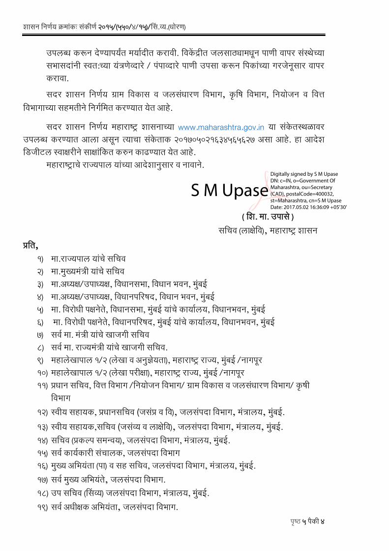
शपिन तनणणय करमपाकः िाकीणण 2015/(550/४/15)/सि.वय.(धोरण)
षठ 5 की 4
उलबध करन दणयपयत मयादीत करपवी. तवक दरीत जलिपठयपमधन पणी वपर िासथचयप िभपिदपानी सवत:चयप यातरणवदपर / ापवदपर पणी उिप करन तकपाचयप गरजनिपर वपर करपवप.
िदर शपिन तनणणय गरपम तवकपि व जलिाधपरण तवभपग, कति तवभपग, तनयोजन व तवतत तवभपगपचयप िहमतीन तनगणतमत करणयपत यत आह.
िदर शपिन तनणणय महपरपषर शपिनपचयप www.maharashtra.gov.in यप िाकतसथळपवर उलबध करणयपत आलप अिन तयपचप िाकतपक 201705021634565627 अिप आह. हप आदश तडजीटल सवपकषरीन िपकषपातकत करन कपढणयपत यत आह.
महपरपषरपच रपजयपल यपाचयप आदशपनिपर व नपवपन.
( तश. मप. उपि )
ितचव (लपकषतव), महपरपषर शपिन परतत,
1) मप.रपजयपल यपाच ितचव 2) मप.मखयमातरी यपाच ितचव 3) मप.अधयकष/उपध यकष, तवधपनिभप, तवधपन भवन, माबई 4) मप.अधयकष/उपध यकष, तवधपनतरिद, तवधपन भवन, माबई 5) मप. तवरोधी कषनत, तवधपनिभप, माबई यपाच कपयालय, तवधपनभवन, माबई 6) मप. तवरोधी कषनत, तवधपनतरिद, माबई यपाच कपयालय, तवधपनभवन, माबई 7) िवण मप. मातरी यपाच खपजगी ितचव 8) िवण मप. रपजयमातरी यपाच खपजगी ितचव. 9) महपलखपपल 1/2 (लखप व अनजञयतप), महपरपषर रपजय, माबई /नपगर 10) महपलखपपल 1/2 (लखप रीकषप), महपरपषर रपजय, माबई /नपगर 11) परधपन ितचव, तवतत तवभपग /तनयोजन तवभपग/ गरपम तवकपि व जलिाधपरण तवभपग/ किी
तवभपग 12) सवीय िहपयक, परधपनितचव (जिापर व तव), जलिादप तवभपग, मातरपलय, माबई. 13) सवीय िहपयक,ितचव (जिावय व लपकषतव), जलिादप तवभपग, मातरपलय, माबई. 14) ितचव (परकल िमनवय), जलिादप तवभपग, मातरपलय, माबई. 15) िवण कपयणकपरी िाचपलक, जलिादप तवभपग 16) मखय अतभयातप (प) व िह ितचव, जलिादप तवभपग, मातरपलय, माबई. 17) िवण मखय अतभयात, जलिादप तवभपग. 18) उ ितचव (सिवय) जलिादप तवभपग, मातरपलय, माबई. 19) िवण अधीकषक अतभयातप, जलिादप तवभपग.
S M UpaseDigitally signed by S M Upase DN: c=IN, o=Government Of Maharashtra, ou=Secretary (CAD), postalCode=400032, st=Maharashtra, cn=S M Upase Date: 2017.05.02 16:36:09 +05'30'
57

शपिन तनणणय करमपाकः िाकीणण 2015/(550/४/15)/सि.वय.(धोरण)
षठ 5 की 5
20) िवण कपयणकपरी अतभयात, जलिादप तवभपग. 21) िवण तपाततरक कपयािन, जलिादप तवभपग 22) िाचपलक, मपतहती व जनिाकण िाचपलनपलय, मातरपलय, माबई. 23) तनवडनसती कपयािन सि.वय. (धोरण).
58
उपसा ससचन योजनचया सकलपनासबधी मारगदरगक ततव व योजनाच आराखड तयार करण.
महाराषटर रासन जलसपदा ववभार
रासन वनणगय, करमाक मसस 1014/ (पर.कर. 337/14)/ मोपर-1 मतरालय, म बई 400 032.
वदनाक :- 30 सपटबर, 2020
वाचा : 1) जलसपदा ववभार,रासन वनणगय, कर. मसस 1014/ (पर.कर. 337/14)/ मोपर-1, वद. 20/11/2014. 2) जलसपदा ववभार, रासन वनणगय कर. ससचन 2015/पर.कर. 24/2015/जस(धोरण), वदनाक 13/01/2017 व 18/01/2017 3) जलसपदा ववभार, रासन वनणगय कर. ससचन 2015/पर.कर. 24/(भार-2)/2015/जस(धोरण), वदनाक 02/02/2017 4)जलसपदा ववभार, पवरपतरक कर. मसस 0208/(83/2008)/मोपर-1, वद. 24/03/2008. 5) जलसपदा ववभार, पवरपतरक कर. उससयो 0609/(366/2009)/मोपर-1, वद.06/07/2009.
परसतावना :-
“उपसा ससचन योजनचया सकलपनासबधी मारगदरगक ततव व योजनाच आराखड तयार करण” या ववषयावरील सदभग कर. 1 वरील रासन वनणगय मधील पवरचछद कर.5 मधय उपसा ससचन योजना सकलपन सबधी मारगदरगक सचना वनरगवमत कलया आहत. तयान सार सवग परकारचया उपसा ससचन योजनाचया मानयता परापत लाभकषतरासाठी सकललपत ववसरग हा स धावरत पनमन पधदतीन सार (12 वदवस वहन कालावधी व दोन वदवस बद धरन) यणा-या महततम पधरवाडी पाणयाचया मारणीवर आधावरत ववसराचया 70 टकक इतका घणयात यावा, अस वनदर आहत. सदर सचना हया पराम खयान म खय वरषग उदा. पपरह, उधवगरामी नवलका इ. कामासाठी लार असन ववतरण वयवसथा ही त या-तया ववतवरका/ लघ ववतवरका इ. वरच परतयकष I.C.A. साठी ससचन वळापतरकान सारच सकललपत कलया जातात.
रासनान नवलकावदार ससचन ववतरण धोरणाबाबतचा सदभग कर. 2 वरील रासन वनणगय वनरगवमत कला आह. तसच नवलकवदार ववतरण परणाली धोरणाबाबत मारगदरगक सचना सदभग कर. 3 वरील रासन पवरपतरकानवय वनरगवमत कलया आहत. सदर पवरपतरकातील पवरचछद कर. 6.0 मधय “ परकलपीय पीक रचनन सार पधरवडयातील जासतीत जासत पाणी ररज ववचारात घऊन ववतरण परणालीच सकलपन कराव” अस वनदवरत आह.
तसच सदभग कर. 4 व 5 वरील रासन पवरपतरकान सार पपरहाची कषमता Peak Discharge चया 70% ववसरासाठी सकललपत करणयाचया सचना हया ववतरण क डाचया खालील पारपारीक ववतरण परणाली वापरणयाचया सदभातील असलयाम ळ तया बवदसत नवलका ववतरण परणालीला लार कराव सकवा
59
रासन वनणगय करमाकः मसस 1014/ (पर.कर. 337/14)/ मोपर-1
पषठ 3 पकी 2
कस याबाबत सवदगधता आह. ही सवदगधता दर करणयासाठी पारपावरक ववतरण परणाली तसच नवलका ववतरण परणाली असणा-या उपसा ससचन योजनासाठी एकवतरत मारगदरगन सचना वनरगवमत करण रासनाचया ववचाराधीन होत.
रासन वनणगय: उपरोकत सदभग कर. 4 व 5 यथील रासन पवरपतरक तसच सदभग कर. 1 यथील रासन वनणगयातील पवरचछद कर. 5.0 अवधकरवमत करन खालील परमाण स धावरत मारगदरगक सचना दणयात यत आहत:
उपसा ससचन योजना तावतरक दषटटया वकफायतरीर, सामावजक दषटटया सवीकत व पयावरणाचया दषटटीन वटकाऊ होणयासाठी तसच वनयोजन व सकलपनाबाबत एकसतरीपणा यणयासाठी खालील मारगदरगक सचनाच काटकोरपण पालन करणयात याव.
क) 12 वदवस वहन कालावधी व 02 वदवस बद अरा पधदतीची ख लया कालवयाची ववतरण वयवसथा असणा-या उपसा ससचन योजनाचया पपरहासाठी सकललपत ववसरग हा स धावरत पनमन पधदतीन सार यणा-या महततम 14 वदवसाचया पाणयाचया मारणीवर आधावरत ववसराचया 70 टकक इतका घणयात यावा.
ख) 12 वदवस वहन कालावधी व 02 वदवस बद अरा पधदतीची बवदसत नवलका पधदतीची ववतरण वयवसथा असणा-या उपसा ससचन योजनाचया पपरहासाठी सकललपत ववसरग हा स धावरत पनमन पधदतीन सार यणा-या महततम 14 वदवसाचया पाणयाचया मारणीवर आधावरत ववसराचया 85 टकक इतका घणयात यावा.
र) आवतगनातील पणग 14 वदवस वहन कालावधी आवण बवदसत नवलका पधदतीची ववतरण वयवसथा असणा-या उपसा ससचन योजनाचया पपरहासाठी सकललपत ववसरग स धावरत पनमन पधदतीन सार यणा-या महततम 14 वदवसाचया पाणयाचया मारणीवर आधावरत ववसरा एवढा घणयात यावा.
घ) बवदसत नवलका पधदतीची ववतरण वयवसथा असणाऱया उपसा ससचन योजनामधय ववतरण परणालीची ववसरग कषमता पपरहाचया ववसरग कषमतरी स सरत असावी.
च) आवगतन कालावधी हा 14 वदवस व 24 तास पपीर असा धरणयात यावा. छ) अवतवरकत पपाची तरतद करणयात यऊ नय.
झ) सवग वनयोजनाधीन उपसा ससचन योजनाच सवगसाधारण आराखड तावतरक वयवहायगतचया दषटटीन मधयवती सकलपवचतर सघटनकडन तपासणी झालयानतरच सकषम सतरावर मानयता दणयात यावी.
60
रासन वनणगय करमाकः मसस 1014/ (पर.कर. 337/14)/ मोपर-1
पषठ 3 पकी 3
सदर रासन वनणगय महाराषटर रासनाचया www.maharashtra.gov.in वबसाईटवर परवसधद करणयात आला असन तयाचा साकताक कर. 202009301631408727 आह. ह आदर वडजीटल सवाकषरीन साकषावकत करन काढणयात यत आह.
महाराषटराच राजयपाल याचया आदर व नावान.
(अ.अ.कपोल) म खय अवभयता, (द.व.पर) व स.स. परत-
1) मा.मतरी (जलसपदा ) याच खाजरी सवचव मतरालय मतरालय म बई 2) मा.राजयमतरी (जलसपदा ) याच खाजरी सवचव मतरालय मतरालय म बई 3) सवीय सहायक, परधान सवचव(जलसपदा), जलसपदा ववभार, मतरालय, म बई. 4) सवीय सहायक, सवचव(लाकषवव), जलसपदा ववभार, मतरालय, म बई. 5) सवीय सहायक, सवचव(परकलप समनवय), जलसपदा ववभार, मतरालय, म बई. 6) महासचालक, सकलपन व सरोधन, महाराषटर अवभयावतरकी सरोधन ससथा,
नावरक. 7) कायगकारी सचालक, (सवग) 8) सवीय सहायक,सवग म खय अवभयता व सह सवचव, जलसपदा ववभार,मतरालय, म बई 9) सवग म खय अवभयता (सथापतय), जलसपदा ववभार,मतरालय, म बई 10) म खय अवभयता (यावतरकी), जलसपदा ववभार, नावरक. 11) म खय अवभयता (ववदय त), जलसपदा ववभार, म बई 12) सवीय सहायक, सवग उप सवचव, जलसपदा ववभार, मतरालय, म बई. 13) सवग अधीकषक अवभयता, (सथापतय, यावतरकी व जलववदय त) जलसपदा ववभार. 14) सवग अवर सवचव, जलसपदा ववभार, मतरालय, म बई. 15) सवग कायगकारी अवभयता (सथापतय, यावतरकी व जलववदय त) जलसपदा ववभार. 16) जलसपदा ववभारातील सवग तावतरक अवधकारी व तावतरक कायासन. परत मोपर-1 कायासन सगरहाथग.
Atul Ashok Kapole
Digitally signed by Atul Ashok Kapole DN: c=IN, o=Government Of Maharashtra, ou=Water Resources Department, postalCode=400032, st=Maharashtra, 2.5.4.20=797fcfe0bb4a86dd814129f50d05c1d249ea6f0acc364c6214f11ff7174bd5ef, serialNumber=ae2c4f4c985d3e984de94324901263d48766ec651dea49d652faf11a96aa98b5, cn=Atul Ashok Kapole Date: 2020.09.30 16:34:02 +05'30'
61