Embed Size (px)
Citation preview
BACHELOR'S DEGREE IN INDUSTRIAL TECHNOLOGY
ENGINEERING
Bachelor’s Thesis
WRAP YARN TECHNOLOGY
Fundamentals and Prototype design
Author: Fco. Javier Massó de Rafael
Director: Artan Sinoimeri
June 2015
Université de Haute Alsace
ENSISA

WRAP YARN TECHNOLOGY: Fundamentals and Prototype design 2
WRAP YARN TECHNOLOGY: Fundamentals and Prototype design 3
Table of Contents
1. PREFACE ................................................................................................................................. 5
1.1. Origins ............................................................................................................................... 5
1.2. Motivation .......................................................................................................................... 5
1.3. Previous knowledge ......................................................................................................... 5
2. INTRODUCTION ...................................................................................................................... 6
3. TEXTILE FUNDAMENTALS ................................................................................................... 7
3.1. Fibers ................................................................................................................................. 7
3.1.1 Fiber length ............................................................................................................... 7
3.1.2 Fiber fineness ........................................................................................................... 8
3.1.3 Fiber strength ........................................................................................................... 9
3.2. From fibers to yarns ....................................................................................................... 10
3.3. Manufacturing process .................................................................................................. 10
3.3.1 Raw material .......................................................................................................... 10
3.3.2 Preparation: Opening and Cleaning ................................................................... 11
3.3.3 Carding .................................................................................................................... 11
3.3.4 Combing .................................................................................................................. 12
3.3.5 Drawing ................................................................................................................... 12
3.3.6 Twisting ................................................................................................................... 13
3.3.7 Spinning .................................................................................................................. 13
3.4. Spinning technologies .................................................................................................... 14
3.4.1 Ring spinning ......................................................................................................... 14
3.4.2 Open-end spinning ................................................................................................ 16
3.4.3 Air-jet spinning ....................................................................................................... 18
3.4.4 Wrap spinning ........................................................................................................ 19
4. PROTOTYPE .......................................................................................................................... 22
4.1. Drafting Unit .................................................................................................................... 23
4.1.1 Principles ................................................................................................................ 23
4.1.2 Alternative 1 ........................................................................................................... 25
4.1.3 Alternative 2 ........................................................................................................... 27
4.1.4 Alternative 3 ........................................................................................................... 28
4.2. Hollow Spindle Unit ........................................................................................................ 30
4.2.1 Principles ................................................................................................................ 30
WRAP YARN TECHNOLOGY: Fundamentals and Prototype design 4
4.2.2 Two Hollow Spindle alternative ............................................................................ 31
4.2.3 Numerical example ................................................................................................ 33
4.2.4 Twisting element .................................................................................................... 34
4.3. Storage unit ..................................................................................................................... 35
4.3.1 Principles ................................................................................................................. 35
4.3.2 Procedure 1 ............................................................................................................ 38
4.3.3 Procedure 2 ............................................................................................................ 40
5. Enterprises .............................................................................................................................. 41
5.1. Schappe Techniques ...................................................................................................... 41
5.2. Bergère de France .......................................................................................................... 44
6. CONCLUSIONS ..................................................................................................................... 46
7. ANNEX ..................................................................................................................................... 47
7.1. False Twist ...................................................................................................................... 47
7.2. BSH0551P21A2A ........................................................................................................... 49
7.3. GBX060008K .................................................................................................................. 53
7.4. LXM32AU62N4 ............................................................................................................... 56
7.5. LXM32MU62N4 .............................................................................................................. 61
8. Bibliography ............................................................................................................................. 65

WRAP YARN TECHNOLOGY: Fundamentals and Prototype design 5
1. PREFACE
1.1. Origins
This project was born from the idea of Mr. Artan SINOIMERI to develop a machine able to
manufacture wrap yarns.
The ENSISA, one of the “École Nationale Supérieure” concerned in the Université Haute-
Alsace, has a large reputation in the field of textile engineering. Along the years, the
university has to adapt to new technologies and new tendencies. Even though the
university already has numerous machines concerning the yarn development, there is still
not a machine capable to develop those specific yarns called wrap yarns.
The lack of machines to create wrap yarns contributes to a lack of study about those
yarns too. That is what made Mr. SINOIMERI want to investigate over that field and try to
reach to have a machine able to treat wrap yarns with according to different parameters.
1.2. Motivation
Despite the fact that in the home university of the writer it is tried to give students the
maximum of knowledge related to the majority of engineering fields, textile engineering is
not even studied nor mentioned.
Nowadays, according to textile engineering, new technologies are being applied and new
products are trying to be reached. As far as this project focuses on the field of textile
engineering, it is an opportunity to open to new knowledge and inquire into this area of
engineering.
1.3. Previous knowledge
As the knowledge in this field of engineering is barely existent, in order to deal with this
project, some background information is needed.
First of all, it is important to understand how textile works. That is the reason why it has
been studied how fibers can be converted into fabrics depending on the fabric wanted.
Furthermore, it is also important to study the three basic fiber properties and other
physical concepts related with yarns, such as false-twist.
Once the general knowledge about fibers has been achieved, it is indispensable to inquire
into the manufacturing process and more over into the last stage of it.
WRAP YARN TECHNOLOGY: Fundamentals and Prototype design 6
2. INTRODUCTION
In textile world, nearly all types of yarns that one can imagine can be created. Some of
them are easier to create, and some others have to deal with more accurate processes.
Those yarns made out of fibers which are difficult to be treated are sometimes wrapped by
a filament in order to give them the consistence needed to develop the yarn. These
particular types of yarns are called wrap yarns.
According to that, the primordial aim of the project is to set the ideas of a future prototype
able to create wrap yarns. To achieve it, it has been done a general study of the existing
machines and possible alternatives.
The prototype that is being sought would have to enable the study and creation of
different types of wrap yarns. For this reason, it has been tried to develop a prototype able
to deal with some particular features to create different types of yarns. Those features
taken into account are the following:
The prototype should have to be able to treat all types of length fibers (long and
short fibers).
The prototype should have to be able to create yarns out of ribbon or roving.
In order to accomplish the objective of the project, first of all it has been studied what the
prototype needs to have. Once the general idea of the prototype has been set, it has been
discussed about how this idea could be achieved. In other words, which are the
alternatives that can make the idea became into a reality. Once the brainstorming of
alternatives has reached all of the possibilities, those which are more suitable are the
ones that have been described and analyzed.
By now, the possibility of developing the prototype looks more achievable and more
documented and studied.
Besides the main objective, there are other two more simple objectives that are also
wanted to be achieved. Both objectives are related with extending the knowledge in textile
engineering. On the one hand, the first aim is to get to know the fibers and their
properties. On the other hand, familiarize with the manufacturing process that fibers follow
to be converted into yarns and inquire into its last stage, the spinning stage.
To achieve those objectives, some books have been greatly useful. Specifically: The
Rieter Manual of Spinning; and Fundamentals of Spun Yarn Technology.
WRAP YARN TECHNOLOGY: Fundamentals and Prototype design 7
3. TEXTILE FUNDAMENTALS
Textile can be described as the process by which fibers are converted into fabrics.
Accordingly, fibers can follow two different processes depending on the fabrics wanted.
On the one hand, if surface fabrics are wanted, three stages can be distinguished. First of
all, textile begins with single fibers. Those fibers are then processed and converted into
yarns and, in closing, yarns are used to fabrics. In relation to the woven fabrics achieved,
they can either be made through weaving or knitting in majority.
On the other hand, if the aim of the process is to create non-woven fabrics, then fibers do
not have to be processed to create yarns because those fabrics are neither woven nor
knitted. In these particular fabrics, long fibers are attached by some chemical, mechanical,
heat or solvent treatment.
3.1. Fibers
As explained in the brief introduction above, fibers are the main component and first step
to create yarns and afterwards fabrics. That is why a general overview of fibers and their
properties are going to be given on the following pages.
The first thing one need to know about spinning fibers is that a yarn can be created with
all different types of fibers. Approximately 90% of fiber consumption is processed into
yarns.
The most commonly classification of fibers is whether if they are organics or inorganics.
Furthermore, both groups can be more specifically classified into natural (those fibers
which come from animals, plants or minerals) or manufactured fibers (artificial fibers made
from petroleum).
Choosing the best fibers to produce the yarn is essential and, therefore, knowing fibers
properties is a must. Fibers have vast different characteristics and properties that can help
to decide which fibers are more suitable to treat. More specifically, there are three
properties which predominate among the others. Those three most important properties
are strength, finest and length and they will be synthetize below.
3.1.1 Fiber length
Fiber length is the first one of the three most important fiber properties. It does not only
influences spinning limit and productivity, via quantity of waste and required turns of twist,
WRAP YARN TECHNOLOGY: Fundamentals and Prototype design 8
but also influences in yarn properties such as yarn strength, yarn evenness or yarn
hairiness.
According to this property, two types of fibers can be distinguished:
Long fibers; such as wool with average fiber lengths ranging from 35 to 350 mm.
Short fibers; for instance cotton, whose fibers can have an approximate length
between 13 and 34 mm.
Fiber length is not only important when purchasing fibers. Very short fibers tend to cause
irregularities in the drafted material and also in the yarn. As it will be explained after, fiber
length is even more important after carding.
As a parameter of fiber length distributions we have the Staple diagram. This diagram
shows, for a random sample taken from fibrous mass, the proportion of fibers that are
greater than specified lengths. It is created by classifying the lengths of each individual
fiber of the sample whether by number or by weight. There exist various Staple diagram
forms depending on fibers materials.
3.1.2 Fiber fineness
Fineness is also a meaningful fiber characteristic. It determines how many fibers contain
the cross-section of a yarn of a given thickness. Additional fibers in cross-section are
beneficial because they provide additional strength and uniformity in the yarn.
It is interesting to know that the minimum number of fibers that cross-section needs to
have is about 30; nonetheless, there are usually over 100 fibers in it.
Fiber fineness influences in yarn through, yarn strength, yarn evenness and yarn fullness.
This fiber property also influences the productivity and the spinning limit.
Most fibers have random section characteristics which are difficult to measure. That is
why it is not possible to determine fineness by reference to the diameter of the fibers;
although there are some exceptions, like wool. Therefore, fineness is commonly specified
in terms of mass to length [tex].
tex = mass [g]
length [km]
Even though the unit code is tex, the most commonly used unit is the dtex. Dtex is the
abbreviation of decitex and it refers to the mass in grams per 10000 meters.
WRAP YARN TECHNOLOGY: Fundamentals and Prototype design 9
To have an idea of some real values, cotton fineness is approximately 1,7 dtex; wool
average fineness ranges in between 2,2 up to 38 dtex; and polyesters have a fineness of
about 1 to 6 dtex.
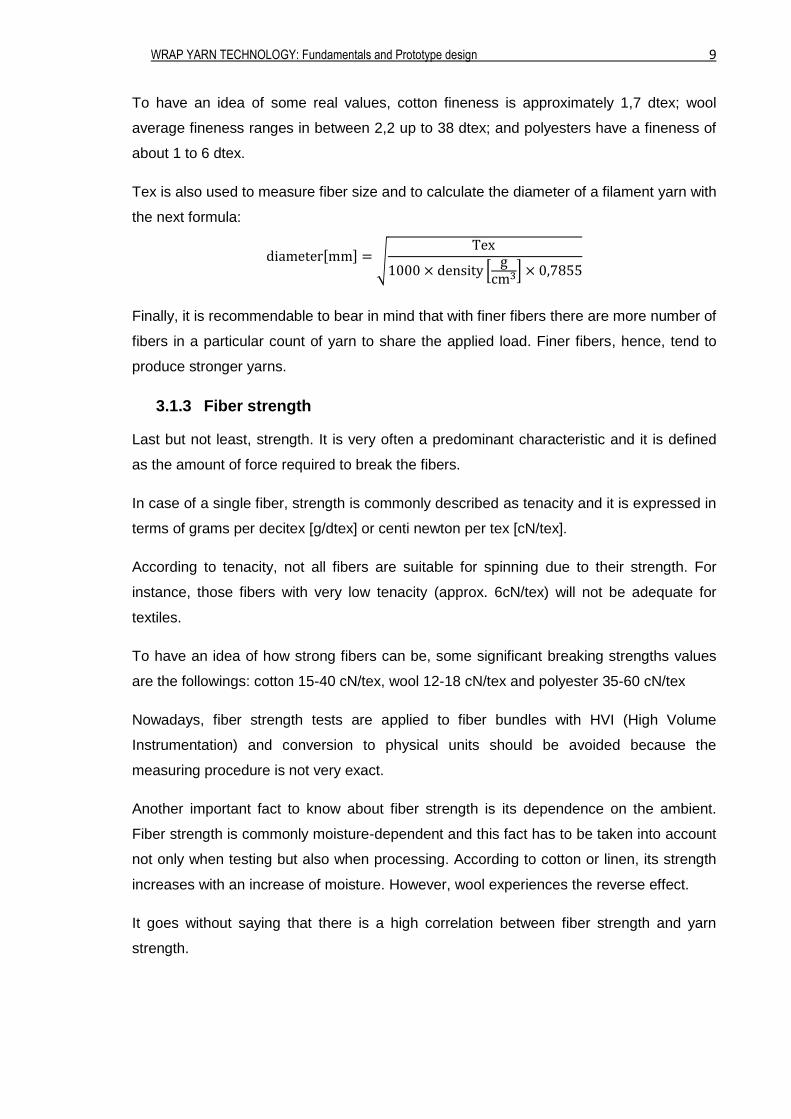
Tex is also used to measure fiber size and to calculate the diameter of a filament yarn with
the next formula:
diameter[mm] = √Tex
1000 × density [g
cm3] × 0,7855
Finally, it is recommendable to bear in mind that with finer fibers there are more number of
fibers in a particular count of yarn to share the applied load. Finer fibers, hence, tend to
produce stronger yarns.
3.1.3 Fiber strength
Last but not least, strength. It is very often a predominant characteristic and it is defined
as the amount of force required to break the fibers.
In case of a single fiber, strength is commonly described as tenacity and it is expressed in
terms of grams per decitex [g/dtex] or centi newton per tex [cN/tex].
According to tenacity, not all fibers are suitable for spinning due to their strength. For
instance, those fibers with very low tenacity (approx. 6cN/tex) will not be adequate for
textiles.
To have an idea of how strong fibers can be, some significant breaking strengths values
are the followings: cotton 15-40 cN/tex, wool 12-18 cN/tex and polyester 35-60 cN/tex
Nowadays, fiber strength tests are applied to fiber bundles with HVI (High Volume
Instrumentation) and conversion to physical units should be avoided because the
measuring procedure is not very exact.
Another important fact to know about fiber strength is its dependence on the ambient.
Fiber strength is commonly moisture-dependent and this fact has to be taken into account
not only when testing but also when processing. According to cotton or linen, its strength
increases with an increase of moisture. However, wool experiences the reverse effect.
It goes without saying that there is a high correlation between fiber strength and yarn
strength.
WRAP YARN TECHNOLOGY: Fundamentals and Prototype design 10
3.2. From fibers to yarns
Once that the most important characteristics of fibers have been defined it is time to
understand how fibers are converted into yarns.
To have a more formal definition of a yarn, we could say that a yarn is a continuous strand
of twisted threads of natural or synthetic fibers, such as wool or nylon, used in the
production of textiles, sewing, and with many other applications.
After reaching that definition, one has to know that yarns can be produced either by
filaments or by staple fibers.
On the one hand, we can find those yarns which are made with filaments. We refer to
filaments as those very long and continuous fibers. According to filament yarns, we can
distinguish between monofilament yarns or multifilament yarns. The first ones are those
which are made from a single fiber and are typically used for fishing line. The second
ones, multifilament yarns, are those made from different fibers. These ones can be
subdivided into twisted, textured or flat (which refers to only grouping together).
On the other hand, yarns can be produced by stapling fibers. As explained previously, it
goes without saying that fibers can have a huge variety of lengths. Due to fiber lengths,
we can subdivide this procedure into yarns produced by stapling long fibers, such as wool,
or by stapling short fibers, for instance cotton. In order to know which fibers can be used
in this method, fibers with the quotient 𝑙
𝑑> 600 (l=length; d=diameter) are considered
textile staple fibers. Otherwise, those fibers with a quotient under 600 are not; for
example, paper cellulosic fibers.
3.3. Manufacturing process
Yarns produced by stapling fibers are going to be the subject of this thesis and so,
following, it is going to be explained how this manufacturing process works.
3.3.1 Raw material
In order to convert fibers into yarns, fibers are purchased in large bales which lately will be
processed. That fibrous mass is referred to as the raw material and it has a big influence
in spinning.
On the one hand, raw material represents about 50-75% of the manufacturing cost of
spinning. On the other hand, not every raw material has the same characteristics, the
WRAP YARN TECHNOLOGY: Fundamentals and Prototype design 11
same facility of productiveness or the same quality. Therefore, choosing the suitable raw
material has to be an accurate decision for yarn making.
3.3.2 Preparation: Opening and Cleaning
As it has been cited above, fibers are shipped in large bales (raw material) in order to
ease their transportation. Before the manufacturing process starts, those bales have to be
opened and, in the majority of the cases, they also need to be cleaned.
Opening is referred to as the breaking up of fiber mass into tufts. There exist plenty of
different types of opening operations and opening devices. In relation with opening, two
stages can be distinguished:
Opening to flocks: Operation which takes place in the blowroom.
Opening to fibers: Operation which takes place card phase.
The aim of cleaning is to eliminate the major quantity of impurities that fibers may contain.
Not all fibers have the same quantity of impurities, and that is why the degree on cleaning
highly depends on the type of fiber and the dust it contains. In outline, cleaning
procedures can be separated into three:
1. Chemical cleaning
2. Wet cleaning
3. Mechanical cleaning
According to opening and cleaning, the degree of cleaning is linearly dependent upon the
degree of opening. Moreover, each opening step should be followed immediately by a
cleaning step without intervening transport because, during transportation, the surfaces
can be exposed to more impurities.
3.3.3 Carding
Once the raw material is completely blended and partially cleaned it goes through the
carding machine. Above all, carding should separate the flock into individual fibers and
pull them into some parallel form in order to prepare the fibers to spinning. This operation
is performed thanks to the huge rollers with wire teeth or hooks that the carding machine
contains.
Nevertheless, this stage has other functions like cleaning or reducing neps (agglomeration
of entangled fibers). Only by means of this fiber separation is it possible to eliminate the
last dirt, especially the finer particles and dust. Furthermore, the carding machine also
discards fibers which are too short to process.
WRAP YARN TECHNOLOGY: Fundamentals and Prototype design 12
After carding, the fibers are converted into a thicker linear structure called sliver. The
sliver obtained is stored at the coiler, called also ‘can’. Multiple slivers can be combined
among them as it will be explained afterwards.
3.3.4 Combing
Combing is not a compulsory process for spinning. It is used when a smoother or finer
yarn is required. This process can be carried out after 2 drawing passages; and, after
combing, 1 or 2 more drawing passages are also necessaries.
For those quality yarns, it is important that the quantity of neps and remnant fragments of
impurity are minimized. Therefore, the process used to remove the short fiber and
remnant impurities is called combing.
Expressed in other words, combing is a process by which the quantity of short fibers and
remnant fragments of impurities present in a carded sliver are minimized to give a clean
sliver.
Combing, accordingly, makes possible the spinning of yarns of fine counts with low
irregularities and a cleaner appearance. This process also results in stronger, smoother,
and more lustrous yarns.
3.3.5 Drawing
After carding, or combing if necessary, the slivers have to be transformed into a uniform
strand. That strand is accomplished in the drawing stage by two different operations:
doubling and drafting.
Doubling is the first operation slivers go through. It consists on placing several slivers
(normally up to 8) in parallel and combining them by using a roller draft. Besides, doubling
improves the irregularity and the blend of the fibers.
After doubling, fibers have to be strengthened. That fiber strength is achieved thanks to a
series of rollers, rotating at different rates of speed, which elongate and stretch the slivers.
Obviously, elongating the slivers produces a reduction of fineness. This operation is
known as drafting.
Normally, the slivers achieved after the drawing stage are once more processed in order
to improve their quality. These slivers are referred to as the ribbon.
As mentioned, the drawing stage is carried out with a series of rollers. Those rollers are
called the drafting system. The most common drafting system is the one which contains
WRAP YARN TECHNOLOGY: Fundamentals and Prototype design 13
three pairs of rollers rotating at different speed. The first rollers have less speed than the
second ones and this gradient of speed is what makes possible a permanent elongation of
the slivers. In order not to break fibers, the distance between those rollers (ratch) is also
important. That distance has to be at greater than the maximum length of the fibers.
Contrarily, each end of the fiber would have a different speed and that would cause a
break in the fibers.
Normally, there is a relation in between the speed of both rollers depending on whether if
the yarn is being made by ribbon or by roving. Afterwards, some values of these relations
between roller speeds are going to be described.
3.3.6 Twisting
Once the ribbon is achieved, it can directly to go through the last stage of the
manufacturing process. That is to say that it can now be spun. Nonetheless, the ribbon
can pass through another stage before spinning. That stage is known as twisting.
Now that the ribbon has been formed, if wanted, its fibers can even elongate more and
have an additional twist. To do so, a machine called the roving frame is used. The roving
provides more strength by thinning and giving a little twist to the ribbon. Due to the name
of this machine, the strands that come outside it are called the roving. Depending on the
yarn wanted, the roving is less or more thinned. At the time the fibers are twisted, the
roving acquires some resistance before breaking.
3.3.7 Spinning
At last, the spinning stage arrives. This stage converts either the ribbon or the roving into
the specific yarns searched.
There exist a massive range of different spinning systems even though not all of them are
suitable for commercial use. The four most typical technologies used in spinning for staple
fibers are the following:
Ring spinning
Open-end spinning
Air jet
Wrap spinning
Choosing one or another spinning system basically depends on the fiber types that can be
spun, the amount of money required and the extensive uses that can be given to the yarn.
WRAP YARN TECHNOLOGY: Fundamentals and Prototype design 14
It is also interesting to know that, once the yarns are created, it is quiet customary to twist
two or more of them together to improve their properties or to overcome subsequent
processing difficulties.
3.4. Spinning technologies
As mentioned above, there are four spinning techniques that predominate among the
others. Hereafter it is going to be explained in broadly those four spinning technologies.
3.4.1 Ring spinning
Ring spinning is the spinning technology quintessential. What makes it useful is the great
number of fabric end uses with advantageous properties obtained with it. But, despite ring
spinning is the most used technology, it has a very low production speed and that is why,
it does not offer the best process economics.
Ring spinning method is a process that uses roller drafting, for attenuating the fiber mass,
and the motion of a guide, called traveller, that circulates freely around a ring to insert
twist and simultaneously wind the formed yarn onto a bobbin. Both ring and traveler
combination is a twisting and winding mechanism.
First of all, the fibers pass through different pairs of rollers called drafting system, as
explained above. The distance between each roller and its pair decreases as the fibers
move along in order to compress the fibers. It is important to notice that drafting system
only can be used when the fibers of the material to be processed have not a wide range of
length.
After those rollers, there is a yarn guide called lappet, and below the lappet there is a ring
with the spindle situated at its center. The lappet, the ring and the spindle are all coaxial.
The traveller, made of metal, normally has the shape of the letter C and it is clipped onto
the ring.
While the traveller goes around the spindle a tubular-shaped bobbin is made. The ring rail
moves up and down the length of the spindle so as to wound the yarn onto the bobbin in
successive layers. Therefore, the diameter of package that is being built is lower than the
ring. The path followed by the yarn is consequently from the nip of the front rollers of the
drafting system, through the eye of the lappet and the loop of the traveller, and onto the
bobbin.
The yarn wounds onto the bobbin at the same linear speed as the front rollers are
delivering the fibers. And this happens due to the rotation of the spindle that can be up to
WRAP YARN TECHNOLOGY: Fundamentals and Prototype design 15
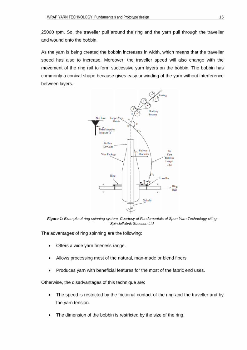
25000 rpm. So, the traveller pull around the ring and the yarn pull through the traveller
and wound onto the bobbin.
As the yarn is being created the bobbin increases in width, which means that the traveller
speed has also to increase. Moreover, the traveller speed will also change with the
movement of the ring rail to form successive yarn layers on the bobbin. The bobbin has
commonly a conical shape because gives easy unwinding of the yarn without interference
between layers.
Figure 1: Example of ring spinning system. Courtesy of Fundamentals of Spun Yarn Technology citing:
Spindelfabrik Suessen Ltd.
The advantages of ring spinning are the following:
Offers a wide yarn fineness range.
Allows processing most of the natural, man-made or blend fibers.
Produces yarn with beneficial features for the most of the fabric end uses.
Otherwise, the disadvantages of this technique are:
The speed is restricted by the frictional contact of the ring and the traveller and by
the yarn tension.
The dimension of the bobbin is restricted by the size of the ring.
WRAP YARN TECHNOLOGY: Fundamentals and Prototype design 16
3.4.2 Open-end spinning
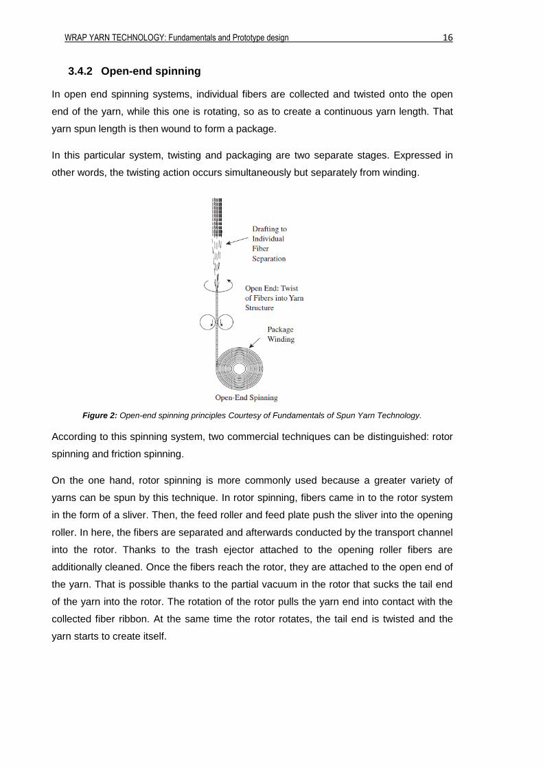
In open end spinning systems, individual fibers are collected and twisted onto the open
end of the yarn, while this one is rotating, so as to create a continuous yarn length. That
yarn spun length is then wound to form a package.
In this particular system, twisting and packaging are two separate stages. Expressed in
other words, the twisting action occurs simultaneously but separately from winding.
Figure 2: Open-end spinning principles Courtesy of Fundamentals of Spun Yarn Technology.
According to this spinning system, two commercial techniques can be distinguished: rotor
spinning and friction spinning.
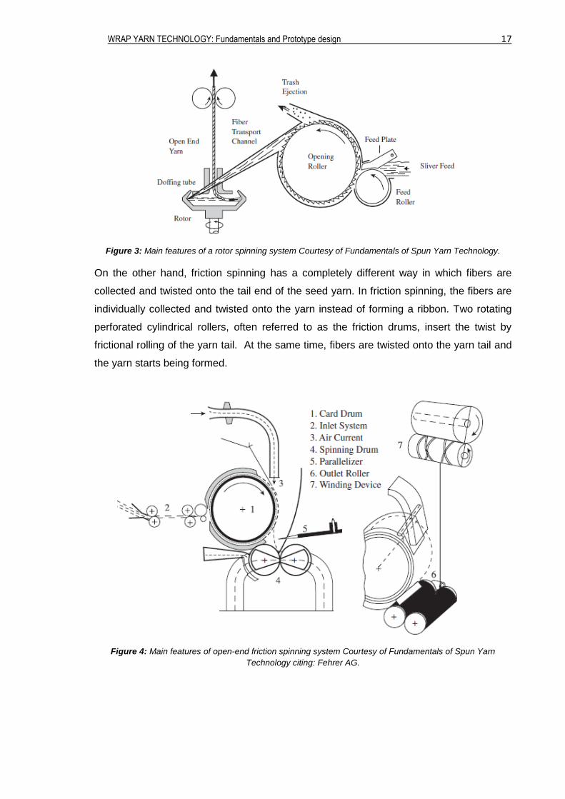
On the one hand, rotor spinning is more commonly used because a greater variety of
yarns can be spun by this technique. In rotor spinning, fibers came in to the rotor system
in the form of a sliver. Then, the feed roller and feed plate push the sliver into the opening
roller. In here, the fibers are separated and afterwards conducted by the transport channel
into the rotor. Thanks to the trash ejector attached to the opening roller fibers are
additionally cleaned. Once the fibers reach the rotor, they are attached to the open end of
the yarn. That is possible thanks to the partial vacuum in the rotor that sucks the tail end
of the yarn into the rotor. The rotation of the rotor pulls the yarn end into contact with the
collected fiber ribbon. At the same time the rotor rotates, the tail end is twisted and the
yarn starts to create itself.
WRAP YARN TECHNOLOGY: Fundamentals and Prototype design 17
Figure 3: Main features of a rotor spinning system Courtesy of Fundamentals of Spun Yarn Technology.
On the other hand, friction spinning has a completely different way in which fibers are
collected and twisted onto the tail end of the seed yarn. In friction spinning, the fibers are
individually collected and twisted onto the yarn instead of forming a ribbon. Two rotating
perforated cylindrical rollers, often referred to as the friction drums, insert the twist by
frictional rolling of the yarn tail. At the same time, fibers are twisted onto the yarn tail and
the yarn starts being formed.
Figure 4: Main features of open-end friction spinning system Courtesy of Fundamentals of Spun Yarn
Technology citing: Fehrer AG.
WRAP YARN TECHNOLOGY: Fundamentals and Prototype design 18
3.4.3 Air-jet spinning
Another known method is air-jet spinning which consist of surface fiber wrapping.
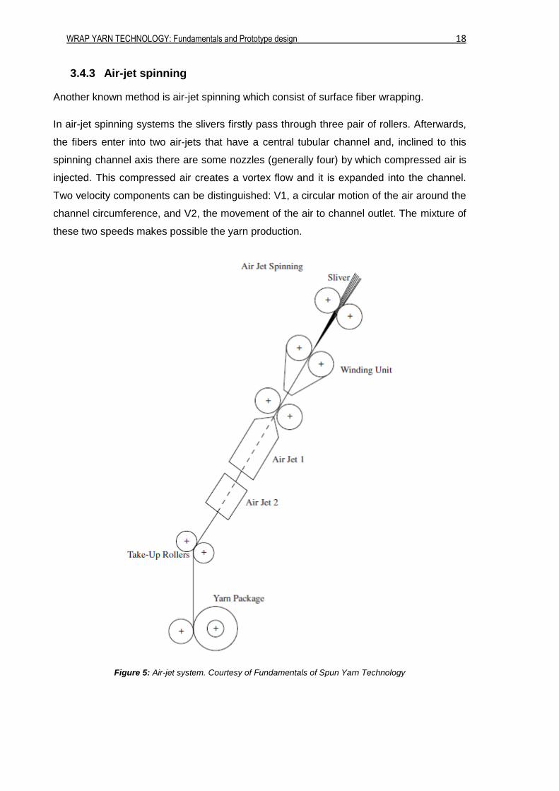
In air-jet spinning systems the slivers firstly pass through three pair of rollers. Afterwards,
the fibers enter into two air-jets that have a central tubular channel and, inclined to this
spinning channel axis there are some nozzles (generally four) by which compressed air is
injected. This compressed air creates a vortex flow and it is expanded into the channel.
Two velocity components can be distinguished: V1, a circular motion of the air around the
channel circumference, and V2, the movement of the air to channel outlet. The mixture of
these two speeds makes possible the yarn production.
Figure 5: Air-jet system. Courtesy of Fundamentals of Spun Yarn Technology
WRAP YARN TECHNOLOGY: Fundamentals and Prototype design 19
3.4.4 Wrap spinning
Last but not least, wrap spinning. This particular system is the one in which the subject of
the thesis will be focused.
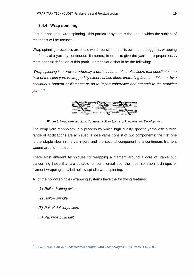
Wrap spinning processes are those which consist in, as his own name suggests, wrapping
the fibers of a yarn by continuous filament(s) in order to give the yarn more properties. A
more specific definition of this particular technique should be the following:
“Wrap spinning is a process whereby a drafted ribbon of parallel fibers that constitutes the
bulk of the spun yarn is wrapped by either surface fibers protruding from the ribbon or by a
continuous filament or filaments so as to impart coherence and strength to the resulting
yarn.” 1
Figure 6: Wrap yarn structure. Courtesy of Wrap Spinning: Principles and Development.
The wrap yarn technology is a process by which high quality specific yarns with a wide
range of applications are achieved. Those yarns consist of two components; the first one
is the staple fiber in the yarn core and the second component is a continuous-filament
wound around the strand.
There exist different techniques for wrapping a filament around a core of staple but,
concerning those that are suitable for commercial use, the most common technique of
filament wrapping is called hollow-spindle wrap spinning.
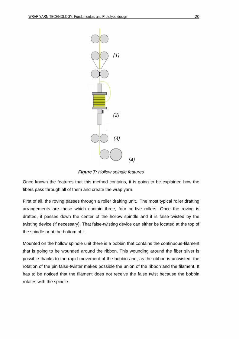
All of the hollow spindles wrapping systems have the following features:
(1) Roller drafting units
(2) Hollow spindle
(3) Pair of delivery rollers
(4) Package build unit
1 LAWRENCE, Carl A. Fundamentals of Spun Yarn Technologies. CRC Press LLC, 2003..
WRAP YARN TECHNOLOGY: Fundamentals and Prototype design 20
Figure 7: Hollow spindle features
Once known the features that this method contains, it is going to be explained how the
fibers pass through all of them and create the wrap yarn.
First of all, the roving passes through a roller drafting unit. The most typical roller drafting
arrangements are those which contain three, four or five rollers. Once the roving is
drafted, it passes down the center of the hollow spindle and it is false-twisted by the
twisting device (if necessary). That false-twisting device can either be located at the top of
the spindle or at the bottom of it.
Mounted on the hollow spindle unit there is a bobbin that contains the continuous-filament
that is going to be wounded around the ribbon. This wounding around the fiber sliver is
possible thanks to the rapid movement of the bobbin and, as the ribbon is untwisted, the
rotation of the pin false-twister makes possible the union of the ribbon and the filament. It
has to be noticed that the filament does not receive the false twist because the bobbin
rotates with the spindle.

WRAP YARN TECHNOLOGY: Fundamentals and Prototype design 21
Once the filament is completely wound around the ribbon, the yarn is finally produced.
Then, the delivery rollers conduct the final yarn into a package build unit in order to store it
and ease its distribution.
All the characteristics and little details of this process are going to be described on the
following part of the thesis while proposing the different ideas for the prototype.
WRAP YARN TECHNOLOGY: Fundamentals and Prototype design 22
4. PROTOTYPE
Once seen all the concepts and general terms about textile, it is time to try to develop the
prototype we are looking for.
As explained in the intro, there are several aspects that have to be taken into
consideration. In any case, the most important characteristic that the prototype has to deal
with is that it has to be capable to treat whether long or short fibers and roving or ribbon.
Those characteristics will add some important properties to bear in mind in some of the
structures of the prototype when discussing the possible alternatives.
In order to obtain the wrap yarn desired the prototype should have to be formed by the
following main structures:
Drafting unit
Hollow spindle unit
Storage unit
As can be seen, the structures that will contain the prototype are nearly the same as all
other hollow spindle wrapping systems have. That is because we are not looking for a
new innovative type of machine to treat fibers, but for a prototype to develop different
types of wrap yarns based on existing machines.
Hereafter, it is going to be explained in detail each of the parts that the prototype may
contain by giving distinct alternatives with some advantages and disadvantages for the
prototype.
WRAP YARN TECHNOLOGY: Fundamentals and Prototype design 23
4.1. Drafting Unit
4.1.1 Principles
The drafting unit, as it has been already explained, consists of a series of rollers that
attenuate the fiber mass.
This particular structure is the one that has to deal with the features of treating long or
short fibers and ribbon or roving. Those features added the following two aspects to the
prototype drafting unit:
Changeability in the distances between rollers.
Changeability in the speeds relations between each pair of rollers.
Those aspects will have to be considered at all times when discussing the possible
alternatives.
Accordingly with the aspects mentioned above, in order to treat long and short fibers the
distance between each pair of roller will have to be changeable for not breaking the fibers.
If a fiber is pinched at the same time by different rollers it will break due to the difference
of speed of each roller that will be transmitted to the fiber.
Moreover, the input material may be presented in two ways, ribbon or roving, and that
particular characteristic demands a changeability in roller speeds.
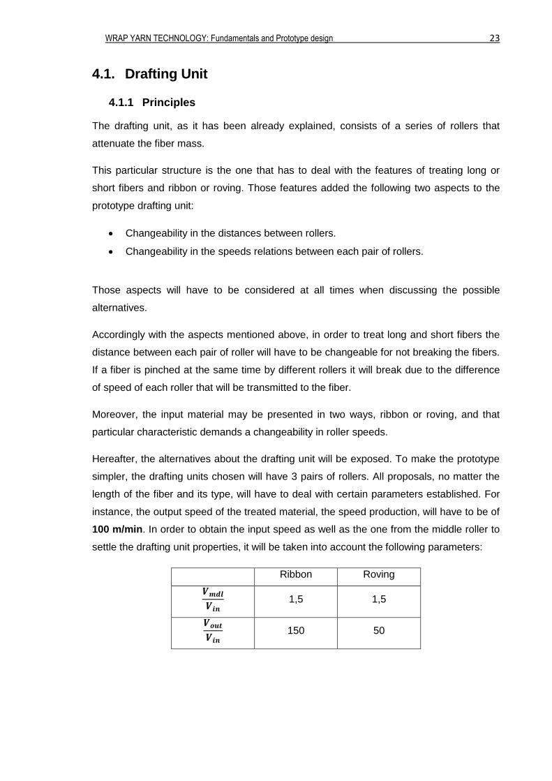
Hereafter, the alternatives about the drafting unit will be exposed. To make the prototype
simpler, the drafting units chosen will have 3 pairs of rollers. All proposals, no matter the
length of the fiber and its type, will have to deal with certain parameters established. For
instance, the output speed of the treated material, the speed production, will have to be of
100 m/min. In order to obtain the input speed as well as the one from the middle roller to
settle the drafting unit properties, it will be taken into account the following parameters:
Ribbon Roving
𝑽𝒎𝒅𝒍
𝑽𝒊𝒏 1,5 1,5
𝑽𝒐𝒖𝒕
𝑽𝒊𝒏 150 50
WRAP YARN TECHNOLOGY: Fundamentals and Prototype design 24
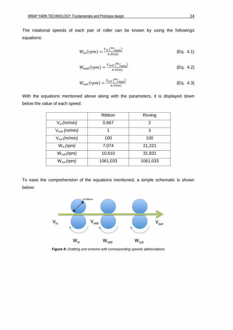
The rotational speeds of each pair of roller can be known by using the followings
equations:
𝑊𝑖𝑛(𝑟𝑝𝑚) =𝑉𝑖𝑛 (
𝑚𝑚𝑖𝑛⁄ )
𝜋·𝐷(𝑚) (Eq. 4.1)
𝑊𝑚𝑑𝑙(𝑟𝑝𝑚) =𝑉𝑚𝑑𝑙 (
𝑚𝑚𝑖𝑛⁄ )
𝜋·𝐷(𝑚) (Eq. 4.2)
𝑊𝑜𝑢𝑡(𝑟𝑝𝑚) =𝑉𝑜𝑢𝑡 (
𝑚𝑚𝑖𝑛⁄ )
𝜋·𝐷(𝑚) (Eq. 4.3)
With the equations mentioned above along with the parameters, it is displayed down
below the value of each speed:
Ribbon Roving
Vin (m/min) 0,667 2
Vmdl (m/min) 1 3
Vout (m/min) 100 100
Win (rpm) 7,074 21,221
Wmdl (rpm) 10,610 31,831
Wout (rpm) 1061,033 1061,033
To ease the comprehension of the equations mentioned, a simple schematic is shown
below:
Figure 8: Drafting unit scheme with corresponding speeds abbreviations
WRAP YARN TECHNOLOGY: Fundamentals and Prototype design 25
4.1.2 Alternative 1
The first alternative taken into account in order to develop the drafting system is to
command the variations of rotation speeds with mechanical transmissions. These types of
mechanisms are used in industrial machines and so, it is interesting to see if they are
suitable for the prototype.
In this particular alternative, one only engine is needed. Therefore, to amortize the
economics, the engine that could be used could be the one from Schneider Electrics® that
is already at the university (BSH0551P31F2A). The brushless technology of this engine
and its characteristics make it suitable for this prototype.
This particular motor (Product chip at section 7.2) turns at a nominal rotational speed of
8000rpm. As explained before, the maximum rotation speed is the one concerning the last
cylinder of the drafting unit which, within the example, ranges in values close to 1000rpm.
To achieve this rotational speed at the last cylinder with an engine of these
characteristics, it is needed to include a reducer (GBX060008K) and also a drive
(LXM32AU60N4 or LXM32MU60N4) to command the speed to desired values. Both the
reducer and the drive have been chosen from Schneider Electrics® catalogue according
to the compatibilities with the engine.
As known, reducing the rotation speed provokes an augment in the engine torque. The
efforts present in the drafting unit commonly are not high, so there will not be any problem
when applying this reducer. Consequently, the engine will have enough torque as to make
the drafting unit function.
Once the last cylinder speed is achieved, the two remaining speeds will be commanded,
as mentioned, by mechanical transmissions, specifically with gears. Lots of combinations
of gears can be used in order to achieve the gear ratio we are looking for. Following, it is
shown a scheme of the combination of gears which is thought to be the most suitable with
the corresponding gear ratios:
WRAP YARN TECHNOLOGY: Fundamentals and Prototype design 26
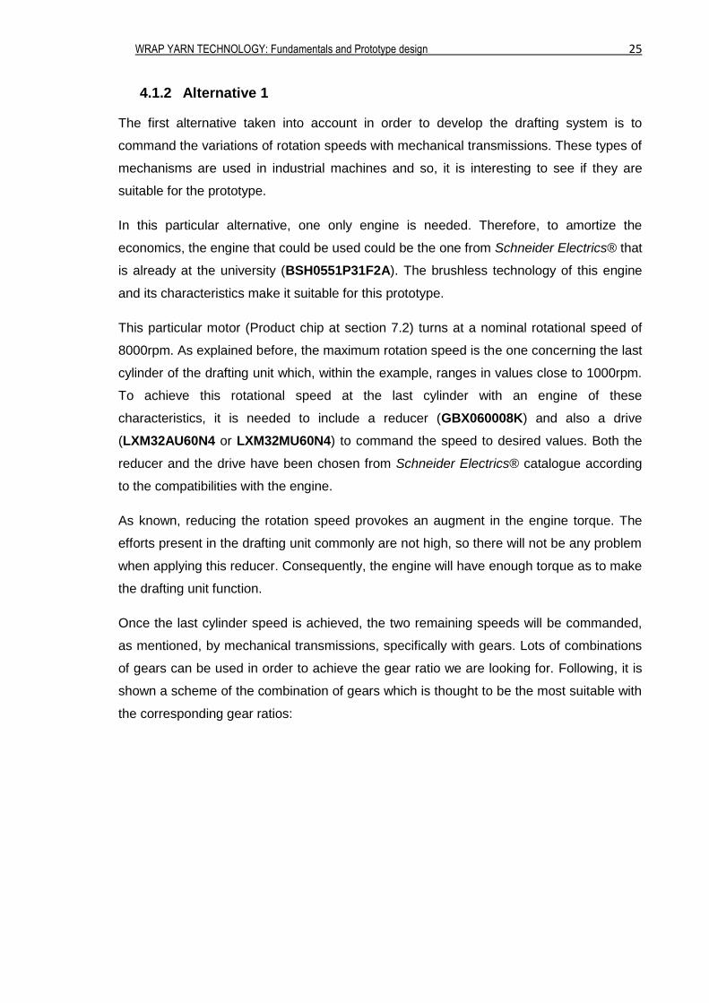
Ribbon: 𝑍𝑚𝑑𝑙
𝑍𝑖𝑛= 1.5 ;
𝑍𝑜𝑢𝑡
𝑍𝑚𝑑𝑙= 100 Roving:
𝑍𝑚𝑑𝑙
𝑍𝑖𝑛= 1.5 ;
𝑍𝑜𝑢𝑡
𝑍𝑚𝑑𝑙= 33.33
Figure 9: Mechanical transmission scheme
The reason why it is thought that this combination would be the most suitable is because it
contains the less number of gears to make all the cylinders rotate at the appropriate
speed and in the same direction. In other words, less space is needed and that makes the
drafting system handier. Of course, the diagram shown above is only an approximation of
what the gear system would look like. If this alternative would be suitable, it would be
necessary to discuss about the number of tooth each gear should have and also about
their radius, all of them according to the gear ratio specified above.
The advantages of this alternative are the outrageous number of possible gears
combinations. We can use several different gears with different tooth numbers and radius.
Furthermore, we could use standard market gears or even try to create our own gears
with a 3D printer. However, creating 3D printed gears can be not useful in account of the
weakness of the materials used nowadays in this technology.
Nonetheless, there also exist some disadvantages. Using mechanical transmissions will
not allow altering easily from long fibers to short fibers because changing distances
between the drafting cylinders will have to deal with removing the gears involved with
others more suitable. That is to say, change the gears for others with bigger or lower
radius in order to increase or decrease the distance between rollers. Moreover, the
speeds relation between the cylinders also varies depending if the yarn will be made from
ribbon or roving. That fact will cause again a need of changing the gears so that they
conform to the new gear ratios and that would take more time and also more gears and
WRAP YARN TECHNOLOGY: Fundamentals and Prototype design 27
calculations. At last, including mechanical transmissions to the drafting unit will make it
heavier and more voluminous.
In order to try to overcome the disadvantages that this alternative presents, it has been
opted to study another alternative.
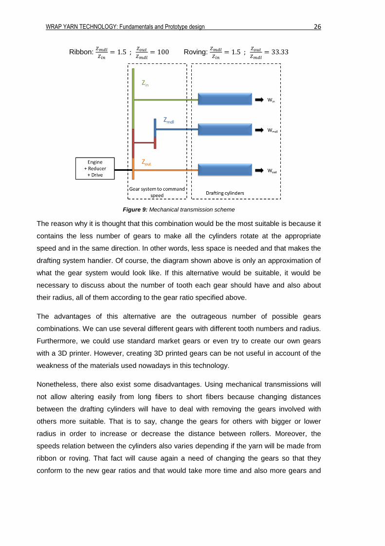
4.1.3 Alternative 2
This second proposal consists of three independent motors, one for each pair of rollers.
The engines chosen for this alternative will be the same as the one mentioned in the first
alternative, due to the accessibility to them.
The three engines will have a nominal rotational speed of 8000rpm and with the presence
of a drive and a reducer the desired speed will be achieved.
The fact that the movement of each pair of roller is carried out by a different engine
involves that the speeds of the pairs of rollers are not physically related. Thereby, it will be
easier to change the distance between the rollers in order to treat different lengths of
fibers, as in the first alterative it was necessary to bear in mind the gears ratios.
Moreover, unlike the first proposal, changing the speeds of the rollers will not have to deal
with changing gears and thinking about its ratios, but only with manipulating the drivers.
This fact implies an ease in speed changeability.
The combination of the engine, the reducer, and the drive could be commanded by a
computer. Thanks to numerical control, the desired speed could be introduced in the
computer and this way the rollers would be able to change their rotational speed.
As in the first alternative, a representative schematic of this second alternative is the
following:
Figure 10: Engines transmission scheme
WRAP YARN TECHNOLOGY: Fundamentals and Prototype design 28
4.1.4 Alternative 3
In case it is not possible to obtain a drafting unit with variable distances between the
rollers, the two alternatives above could not be used to spin both long and short fibers. To
resolve this problem, a third alternative is proposed. More than an alternative, it is an
implementation applicable to both of the previous two alternatives.
That implementation consists of acquiring two different drafting arrangements instead of
only one. Each of those two drafting units will have an individual purpose: one will be used
to spin short fibers and the other will be used for long fibers.
The problem that presents this alternative appears when trying to give the speed to the
rollers of both drafting arrangements.
The simplest way to do so will be to treat both drafting units per separate, that is to say, to
make them function with any of the two alternatives mentioned before but with no
correlation between them. But, in order to economize, it is better to see if there is a way to
connect both drafting arrangements with only one power system.
To achieve this aim, a research has been done and it has been found that the best way to
relate both drafting arrangements is with the system called universal joint or Cardan joint;
which allows joining two non-collinear axes. Its objective is to transmit the rotational
movement of one shaft to the other despite the non-collinearity. The main problem that
appears with this joint is that, by its configuration, the shaft at which it is given the
transmission does not rotate with a constant speed. However, if two Cardan joints are
placed in series and the first shaft and the last one are parallel, these differences in
rotation speed are canceled and both the last and the first shafts rotate at a regular and
equal speed. Thanks to the parallelism of the rollers from both drafting units, this particular
concept is the most suitable to be applied in order to relate the rotation speeds of both
drafting units by only the use of one driving mechanism.
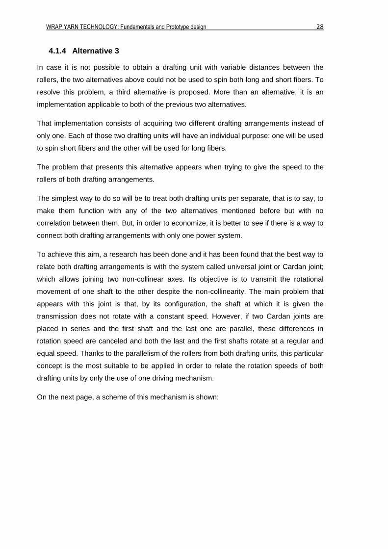
On the next page, a scheme of this mechanism is shown:
WRAP YARN TECHNOLOGY: Fundamentals and Prototype design 29
Figure 11: Cardan joint mechanism scheme
As the scheme shows, only two Cardan joints mechanisms are needed because the lasts
cylinders will be collinear.
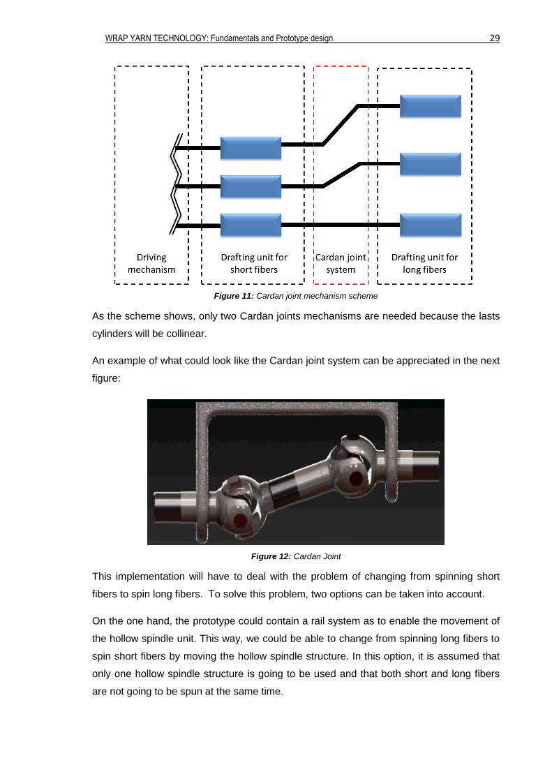
An example of what could look like the Cardan joint system can be appreciated in the next
figure:
Figure 12: Cardan Joint
This implementation will have to deal with the problem of changing from spinning short
fibers to spin long fibers. To solve this problem, two options can be taken into account.
On the one hand, the prototype could contain a rail system as to enable the movement of
the hollow spindle unit. This way, we could be able to change from spinning long fibers to
spin short fibers by moving the hollow spindle structure. In this option, it is assumed that
only one hollow spindle structure is going to be used and that both short and long fibers
are not going to be spun at the same time.
WRAP YARN TECHNOLOGY: Fundamentals and Prototype design 30
On the other hand, instead of having one only hollow spindle unit and a movement
system, two fixed hollow spindle units can be used. One would be used for treating short
fibers and the other one for long fibers. This alternative will enable, if necessary, to treat
both long and short fibers at the same time. More details of this particular option are
clarified in section 4.2.2.
As explained, with this implementation both drafting units will be functioning at the same
time even though, possibly, only one of them will have a purpose. From an energetic point
of view, that implementation would not be considered as suitable because it implies a loss
of energy. That is certain, but it is reminded that it is a prototype what is being tried to
achieve, and not a fully operable industrial machine. That is the reason why that energy
loss does not include any impediment.
4.2. Hollow Spindle Unit
4.2.1 Principles
As we have been discussing throughout the project, the aim of it is to achieve those wrap
yarns wanted. Now, it is time to settle the parameters of the hollow spindle unit.
According to that, the ribbon or the roving coming from the drafting unit would have to be
wrapped by a filament. That filament will be stored around a bobbin and, as the fiber
strand passes through the center of that bobbin, the filament will wrap it thanks to the
rotation speed given to the bobbin.
In general terms, combining the rotation speed of the bobbin with the vertical speed of the
fiber strand will be the key of the wrapping yarn. More rotation speed with less vertical
speed will produce a much wrapped yarn and vice versa. In order to measure if the yarn is
more or less wrapped the next formula will be applied:
𝐴𝑚𝑜𝑢𝑛𝑡 𝑜𝑓 𝑤𝑟𝑎𝑝𝑝𝑖𝑛𝑔 =𝑊𝑏𝑜𝑏𝑏𝑖𝑛
𝑉𝑜𝑢𝑡 [
𝑟𝑒𝑣 𝑜𝑓 𝑏𝑜𝑏𝑏𝑖𝑛
𝑚 𝑜𝑓 𝑦𝑎𝑟𝑛 ] (Eq. 4.4)
For the purpose of giving a certain rotation speed to the bobbin another engine is needed.
Again, the engine that is already at the University is suitable for this purpose. But, as
mentioned before, when looking for a much wrapped yarn, it is more convenient to
accomplish a high bobbin rotation speed. As the engine provides a speed of 8000rpm it
would be suitable to include a system to augment and vary that speed. To obtain this
augmentation of speed, a gears system can be used. This system should be as simple as
possible. That is why only two toothed wheels are going to be used. In order to make the
prototype as much trustworthy to the existent machines, those gears will be not directly
WRAP YARN TECHNOLOGY: Fundamentals and Prototype design 31
physically connected but connected by a toothed belt. As usual, an additional gear will be
also included to maintain the contact and tense the belt. The fact of connecting both
toothed wheels with a belt also contributes to an ease to vary the speed by changing
those gears and a diminution of lubrication to the system.
According to the following equation, whatever desired rotation speed of the bobbin can be
obtained depending on the teeth of the gears:
𝑊𝑒𝑛𝑔𝑖𝑛𝑒𝑍𝑒𝑛𝑔𝑖𝑛𝑒 = 𝑊𝑏𝑜𝑏𝑏𝑖𝑛𝑍𝑏𝑜𝑏𝑏𝑖𝑛 (Eq. 4.5)
It is important to remark that, in order to let the yarn pass through the gear attached to the
bobbin, this one has to contain a hole on its center.
4.2.2 Two Hollow Spindle alternative
After describing the mechanisms of a single hollow spindle, we can get back to the
alternative of having two different hollow spindles. If this idea would be put into practice,
both hollow spindle units would be subjected to the same characteristics mentioned
above. For instance, both of them will turn thanks to the same double sided toothed belt
which will transmit the rotation movement. That is to say that both units will be turning
equally and at the same time.
According to this alternative, three possible ways of spinning can be distinguished:
The prototype only treats short fibers.
The prototype only treats long fibers.
The prototype treats both short and long fibers.
If both short and long fibers are being treated at the same time, apparently does not imply
any problem. The difficulties appear with the first two options. When only one hollow
spindle is treating fibers and the other one is not, as mentioned, both of them will be
turning. That means that while one unit will be working, the other unit will be heating itself
and supporting useless efforts, as well as implying an energetic loose. Moreover, having
elements turning around us is a danger.
In order to solve these problems, it has been thought of attaching a mechanism so as to
stop the hollow spindle unit that is not being used. First of all, to maintain the contact
between the gear and the belt as to keep the hollow spindles rotate, a pair of plain
cylinders will be used. So, if we only want to treat one type of fibers, we would be capable
of removing the cylinders so that the contact between the gear of the non-wanted hollow
spindle and the belt would be lost. Without contact, there is not movement and the
WRAP YARN TECHNOLOGY: Fundamentals and Prototype design 32
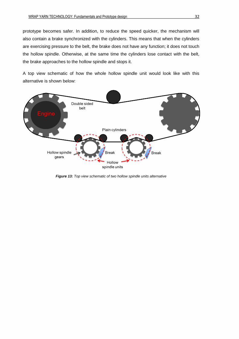
prototype becomes safer. In addition, to reduce the speed quicker, the mechanism will
also contain a brake synchronized with the cylinders. This means that when the cylinders
are exercising pressure to the belt, the brake does not have any function; it does not touch
the hollow spindle. Otherwise, at the same time the cylinders lose contact with the belt,
the brake approaches to the hollow spindle and stops it.
A top view schematic of how the whole hollow spindle unit would look like with this
alternative is shown below:
Figure 13: Top view schematic of two hollow spindle units alternative
WRAP YARN TECHNOLOGY: Fundamentals and Prototype design 33
4.2.3 Numerical example
Once the ideas of the wrapping unit have been settle, it is given a numerical example of
how one can achieve all the values wanted concerning this unit.
The rotation speed of the engine it has been said that it is 8000rpm. According to the
numbers presented at the beginning of this chapter, the production speed is about
100m/min. Imagine that for the desired yarn an amount of wrapping of 300 revolutions of
filament per meter of yarn is wanted. According to this numbers, the following features can
be obtained:
Rotation speed of the bobbin:
When knowing the amount of wrapping wanted and the speed production we can
obtain which is the appropriate rotation speed of the bobbin. By using (Eq.4.4) and
isolating the unknown variable we obtain:
Wbobbin = Vout × Amount of wrapping = 100m
min× 300
rev
m= 30000 rpm
This way, in order to achieve the wrap yarn wanted, the bobbin should have a
rotation speed of 30000 rpm.
Number of teeth of the gears:
Once we know the rotation speed of the bobbin, by using and developing (Eq.4.5)
we obtain the gear ratio of the teeth wheels.
Zengine
Zbobbin=
Wengine
Wbobbin=
30000 rpm
8000 rpm= 3.75
With this gear ratio we obtain the following combinations of teeth wheels:
Zbobbin Zengine
Zbobbin Zengine
16 60 40 150
20 75 44 165
24 90 48 180
28 105 52 195
32 120 56 210
36 135 60 225
After achieving these tables, the only thing left is to decide which pair of wheels
are more easily reachable for us and attach them to the prototype.
WRAP YARN TECHNOLOGY: Fundamentals and Prototype design 34
Pitch:
Additionally, thanks to the amount of wrapping, we can also calculate the distance
between each revolution of the wrapping filament as:
Pitch =1000 mm
Amount of wrapping=
1000 mm
300revm
= 3.33 mm
With this example as a pattern, we are able to achieve all the details needed in order to
achieve other types of yarns.
4.2.4 Twisting element
As commented along the pages above, some short fibers present difficulties when treated.
In order to overcome those difficulties, providing a false-twist is a must. As explained in
the ANNEX 7.1, applying a false-twist to fibers gives them a torsion which will help its
treatment. Therefore, the bobbin would have to contain some sort of a false-twist
mechanism. In addition, this false-twist applied is not contradictorily with long fibers so, it
will be suitable for both long and short fibers.
When applying the false-twist two alternatives can be discussed: above or below the
bobbin. But, the closer to the end of the drafting unit will occur the false-twist, the better. In
order to give the appropriate time to make the false torsion disappear before storing the
finished yarn, it is preferred to apply the false-twist above the bobbin.
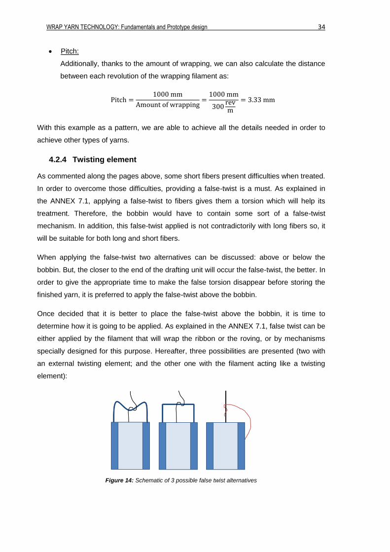
Once decided that it is better to place the false-twist above the bobbin, it is time to
determine how it is going to be applied. As explained in the ANNEX 7.1, false twist can be
either applied by the filament that will wrap the ribbon or the roving, or by mechanisms
specially designed for this purpose. Hereafter, three possibilities are presented (two with
an external twisting element; and the other one with the filament acting like a twisting
element):
Figure 14: Schematic of 3 possible false twist alternatives
WRAP YARN TECHNOLOGY: Fundamentals and Prototype design 35
As it can be seen in section 5.2, those three possibilities shown above are quite similar to
the ones used in real enterprises.
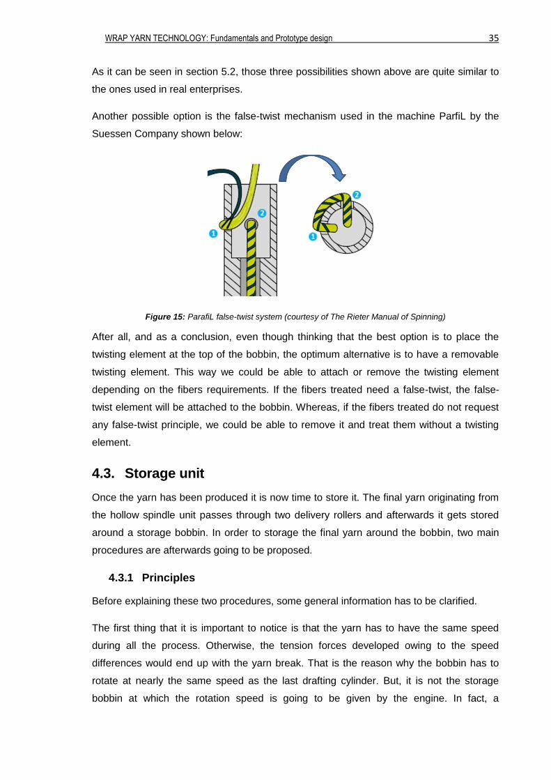
Another possible option is the false-twist mechanism used in the machine ParfiL by the
Suessen Company shown below:
Figure 15: ParafiL false-twist system (courtesy of The Rieter Manual of Spinning)
After all, and as a conclusion, even though thinking that the best option is to place the
twisting element at the top of the bobbin, the optimum alternative is to have a removable
twisting element. This way we could be able to attach or remove the twisting element
depending on the fibers requirements. If the fibers treated need a false-twist, the false-
twist element will be attached to the bobbin. Whereas, if the fibers treated do not request
any false-twist principle, we could be able to remove it and treat them without a twisting
element.
4.3. Storage unit
Once the yarn has been produced it is now time to store it. The final yarn originating from
the hollow spindle unit passes through two delivery rollers and afterwards it gets stored
around a storage bobbin. In order to storage the final yarn around the bobbin, two main
procedures are afterwards going to be proposed.
4.3.1 Principles
Before explaining these two procedures, some general information has to be clarified.
The first thing that it is important to notice is that the yarn has to have the same speed
during all the process. Otherwise, the tension forces developed owing to the speed
differences would end up with the yarn break. That is the reason why the bobbin has to
rotate at nearly the same speed as the last drafting cylinder. But, it is not the storage
bobbin at which the rotation speed is going to be given by the engine. In fact, a
WRAP YARN TECHNOLOGY: Fundamentals and Prototype design 36
complementary bobbin is going to be attached at the storage unit and it is that bobbin the
one that is going to receive directly the rotation speed.
The use of both bobbins is essential. When wrapping the yarn around a bobbin the
diameter of this particular bobbin increases with the layers. Nevertheless, the production
speed desired at all times is constant. So, if the yarn would be directly wrapped around
the storage bobbin, the rotational speed of it would have to decrease continuously. That is
the reason why the constant rotational speed is transmitted to the complementary bobbin.
The storage bobbin, hence, rotates thanks to the friction with the complementary bobbin.
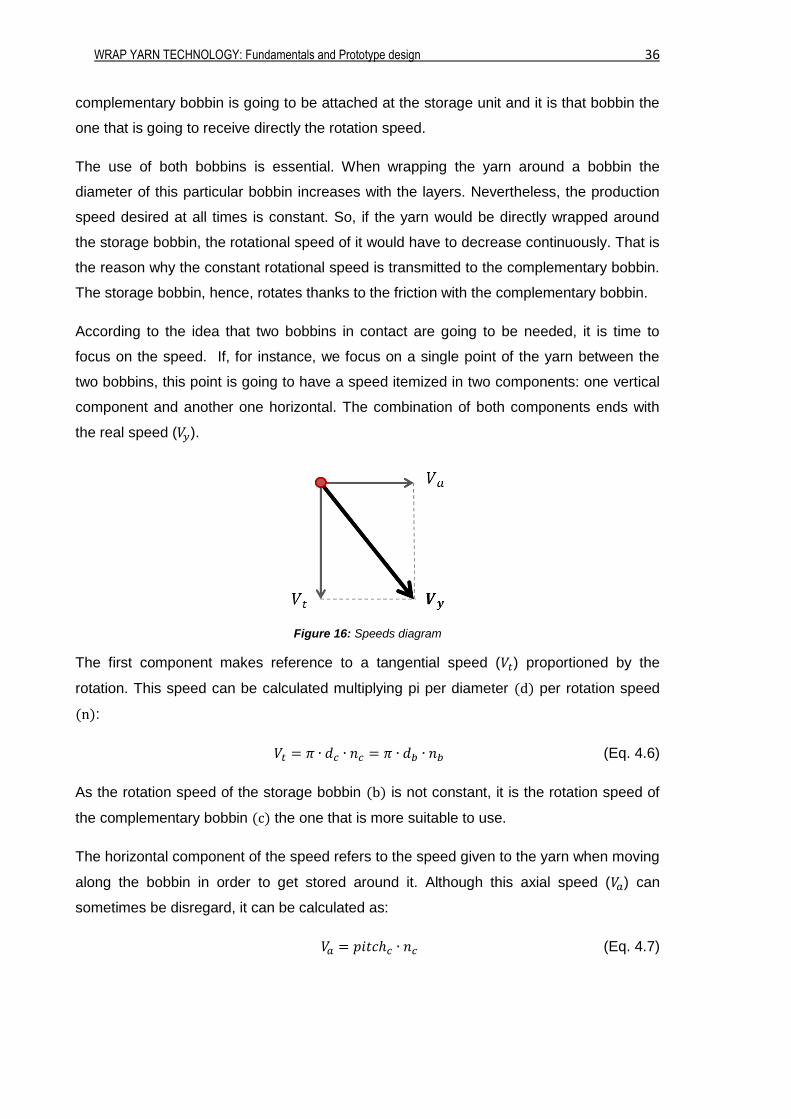
According to the idea that two bobbins in contact are going to be needed, it is time to
focus on the speed. If, for instance, we focus on a single point of the yarn between the
two bobbins, this point is going to have a speed itemized in two components: one vertical
component and another one horizontal. The combination of both components ends with
the real speed (𝑉𝑦).
Figure 16: Speeds diagram
The first component makes reference to a tangential speed (𝑉𝑡) proportioned by the
rotation. This speed can be calculated multiplying pi per diameter (d) per rotation speed
(n):
𝑉𝑡 = 𝜋 ∙ 𝑑𝑐 ∙ 𝑛𝑐 = 𝜋 ∙ 𝑑𝑏 ∙ 𝑛𝑏 (Eq. 4.6)
As the rotation speed of the storage bobbin (b) is not constant, it is the rotation speed of
the complementary bobbin (c) the one that is more suitable to use.
The horizontal component of the speed refers to the speed given to the yarn when moving
along the bobbin in order to get stored around it. Although this axial speed (𝑉𝑎) can
sometimes be disregard, it can be calculated as:
𝑉𝑎 = 𝑝𝑖𝑡𝑐ℎ𝑐 ∙ 𝑛𝑐 (Eq. 4.7)
WRAP YARN TECHNOLOGY: Fundamentals and Prototype design 37
The mathematical combination of both equations, (Eq. 4.6) and (Eq. 4.7), gives us the real
speed of the winding. In fact, we can refer to this winding speed as the speed of the yarn
(𝑉𝑦):
𝑉𝑦 = √𝑉𝑡2 + 𝑉𝑎
2 (Eq. 4.8)
This particular speed is the one that would have to be constant and equal to the
production speed in order to not break the yarn. This way, the yarn will not be once stretch
and other times slackened.
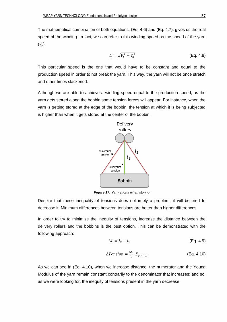
Although we are able to achieve a winding speed equal to the production speed, as the
yarn gets stored along the bobbin some tension forces will appear. For instance, when the
yarn is getting stored at the edge of the bobbin, the tension at which it is being subjected
is higher than when it gets stored at the center of the bobbin.
Figure 17: Yarn efforts when storing
Despite that these inequality of tensions does not imply a problem, it will be tried to
decrease it. Minimum differences between tensions are better than higher differences.
In order to try to minimize the inequity of tensions, increase the distance between the
delivery rollers and the bobbins is the best option. This can be demonstrated with the
following approach:
∆𝐿 = 𝑙2 − 𝑙1 (Eq. 4.9)
∆𝑇𝑒𝑛𝑠𝑖𝑜𝑛 =∆𝐿
𝑙1∙ 𝐸𝑦𝑜𝑢𝑛𝑔 (Eq. 4.10)
As we can see in (Eq. 4.10), when we increase distance, the numerator and the Young
Modulus of the yarn remain constant contrarily to the denominator that increases; and so,
as we were looking for, the inequity of tensions present in the yarn decrease.
WRAP YARN TECHNOLOGY: Fundamentals and Prototype design 38
Taking into account the general terms of the storage unit described above, the two
procedures of storing units are going to be presented.
4.3.2 Procedure 1
This storage process consists on a complementary bobbin provided with rails that permits
to guide the yarn to get stored around the storage bobbin.
Once the yarn has been manufactured, it is conducted to that specific bobbin in order to
make it pass through its rails. The yarn follows the rails thanks to the rotation movement
of the bobbin around its own axis and it gets stored around the storage bobbin. As
explained above, is this specific bobbin the one that rotates thanks to the engine.
In order to economize the prototype, the same engine of the drafting system could be
used to also provide the rotation of the storage unit. To provide that rotation speed, two
toothed wheels interconnected by a toothed belt are going to be attached. One toothed
wheel will be placed at the last drafting cylinder, and the other one at the complementary
bobbin. The toothed belt will be used because it is the best way to enable the
transmission of movement without contact.
As explained before, the horizontal speed component cannot always be disregard, and so
the rotation speed of the last cylinder and the rotation speed of the bobbin have to be
different in order to not break the yarn. According to this, there will have to be a gear ratio
between the cylinder and the bobbin in order to decrease the speed. This gear ratio could
be changed as desired by changing the gears attached to the complementary bobbin.
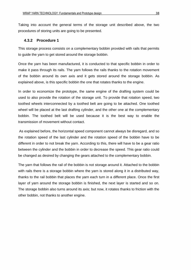
The yarn that follows the rail of the bobbin is not storage around it. Attached to the bobbin
with rails there is a storage bobbin where the yarn is stored along it in a distributed way,
thanks to the rail bobbin that places the yarn each turn in a different place. Once the first
layer of yarn around the storage bobbin is finished, the next layer is started and so on.
The storage bobbin also turns around its axis; but now, it rotates thanks to friction with the
other bobbin, not thanks to another engine.
WRAP YARN TECHNOLOGY: Fundamentals and Prototype design 39
Figure 18: Storage unit procedure 1
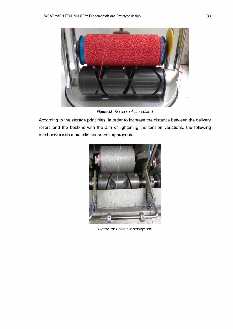
According to the storage principles, in order to increase the distance between the delivery
rollers and the bobbins with the aim of lightening the tension variations, the following
mechanism with a metallic bar seems appropriate:
Figure 19: Enterprise storage unit
WRAP YARN TECHNOLOGY: Fundamentals and Prototype design 40
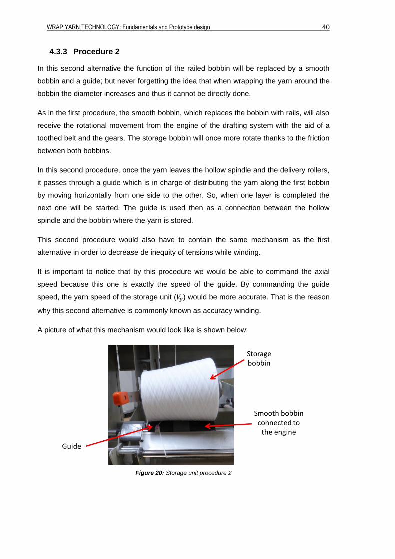
4.3.3 Procedure 2
In this second alternative the function of the railed bobbin will be replaced by a smooth
bobbin and a guide; but never forgetting the idea that when wrapping the yarn around the
bobbin the diameter increases and thus it cannot be directly done.
As in the first procedure, the smooth bobbin, which replaces the bobbin with rails, will also
receive the rotational movement from the engine of the drafting system with the aid of a
toothed belt and the gears. The storage bobbin will once more rotate thanks to the friction
between both bobbins.
In this second procedure, once the yarn leaves the hollow spindle and the delivery rollers,
it passes through a guide which is in charge of distributing the yarn along the first bobbin
by moving horizontally from one side to the other. So, when one layer is completed the
next one will be started. The guide is used then as a connection between the hollow
spindle and the bobbin where the yarn is stored.
This second procedure would also have to contain the same mechanism as the first
alternative in order to decrease de inequity of tensions while winding.
It is important to notice that by this procedure we would be able to command the axial
speed because this one is exactly the speed of the guide. By commanding the guide
speed, the yarn speed of the storage unit (𝑉𝑦) would be more accurate. That is the reason
why this second alternative is commonly known as accuracy winding.
A picture of what this mechanism would look like is shown below:
Figure 20: Storage unit procedure 2
WRAP YARN TECHNOLOGY: Fundamentals and Prototype design 41
5. Enterprises
An essential part of this project is to know what type of mechanisms or machines are used
by real enterprises. It is remind that the aim of the project is not to create a new wrap yarn
machine but to develop a prototype by gathering different parts of existing machines. That
is the reason why knowing what type of machines are the enterprises using is a must.
To acquire this knowledge, two enterprises which develop yarns of the characteristics
wanted have been contacted and visited. Those two enterprises are: Schappe Techniques
and Bergère de France.
5.1. Schappe Techniques
Schappe Techniques is an enterprise with a known reputation for the spinning of the latest
generation of advanced technical fibers. The technical yarns developed by this enterprise
have numerous applications in nowadays industrial fields such as composites, individual
protection, packing, glass industry or technical sewing threads.
In order to achieve those wrap yarns, Schappe Techniques uses the ParafiL wrap
spinning system by the Suessen Company. The machine that we could be able to see and
analyze treated some sort of metallic fibers. The nature of these fibers (its thickness)
explains the no presence of false-twist. Moreover, metallic fibers are abrasive and the
efforts between the fibers and the twisting element could end breaking that element.
Due to the confidentiality of the enterprise, not much information could be extracted.
However, some photographs of the Schappe Techniques system are shown below and
commented according to what has been studied.
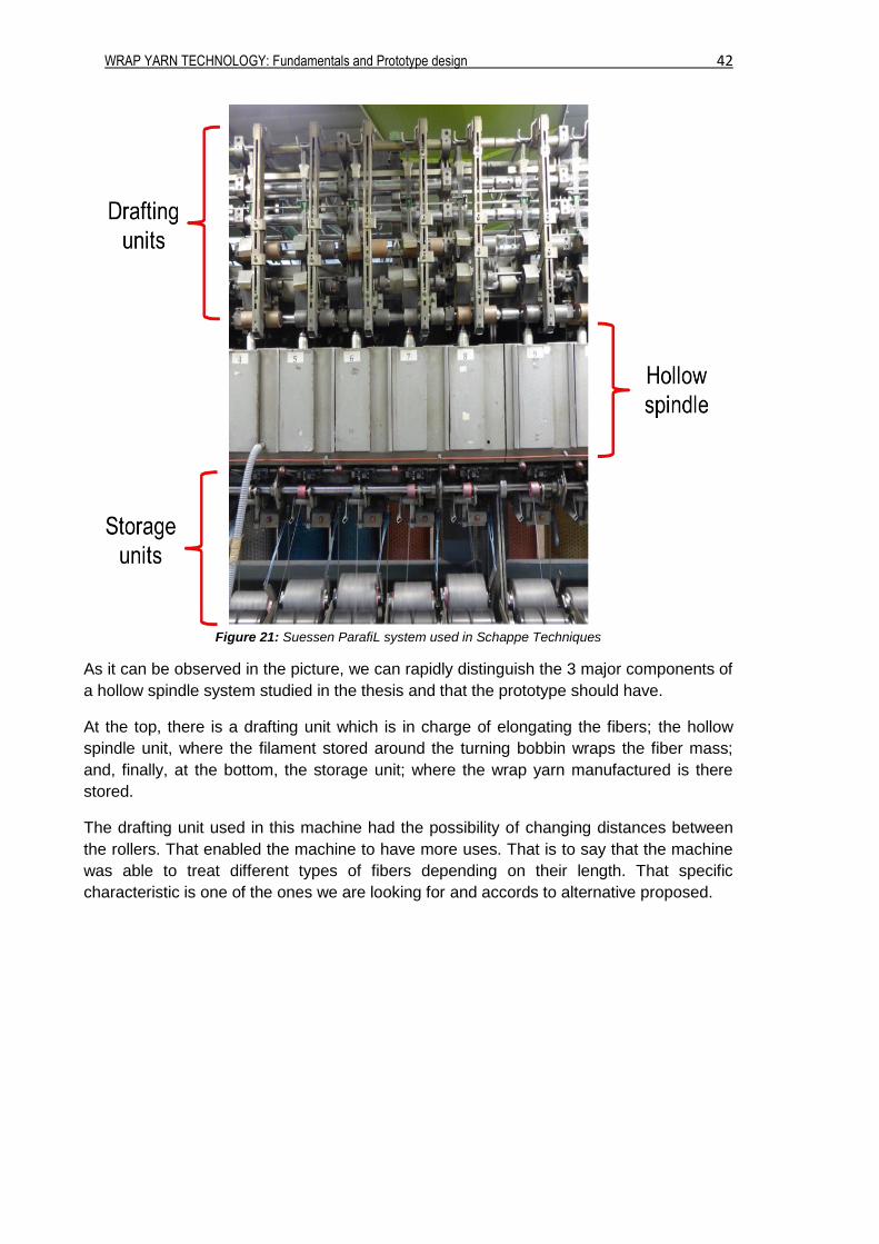
The picture on the next page shows the complete Suessen ParafiL system used to
develop the wrapp yarns of the enterprise.
WRAP YARN TECHNOLOGY: Fundamentals and Prototype design 42
Figure 21: Suessen ParafiL system used in Schappe Techniques
As it can be observed in the picture, we can rapidly distinguish the 3 major components of
a hollow spindle system studied in the thesis and that the prototype should have.
At the top, there is a drafting unit which is in charge of elongating the fibers; the hollow
spindle unit, where the filament stored around the turning bobbin wraps the fiber mass;
and, finally, at the bottom, the storage unit; where the wrap yarn manufactured is there
stored.
The drafting unit used in this machine had the possibility of changing distances between
the rollers. That enabled the machine to have more uses. That is to say that the machine
was able to treat different types of fibers depending on their length. That specific
characteristic is one of the ones we are looking for and accords to alternative proposed.
WRAP YARN TECHNOLOGY: Fundamentals and Prototype design 43
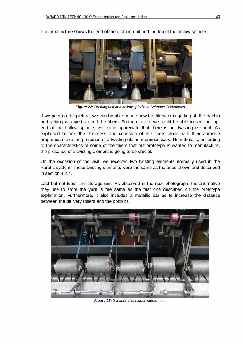
The next picture shows the end of the drafting unit and the top of the hollow spindle.
Figure 22: Drafting unit and hollow spindle at Schappe Techniques
If we peer on the picture, we can be able to see how the filament is getting off the bobbin
and getting wrapped around the fibers. Furthermore, if we could be able to see the top-
end of the hollow spindle, we could appreciate that there is not twisting element. As
explained before, the thickness and cohesion of the fibers along with their abrasive
properties make the presence of a twisting element unnecessary. Nonetheless, according
to the characteristics of some of the fibers that out prototype is wanted to manufacture,
the presence of a twisting element is going to be crucial.
On the occasion of the visit, we received two twisting elements normally used in the
ParafiL system. Those twisting elements were the same as the ones shown and described
in section 4.2.4.
Last but not least, the storage unit. As observed in the next photograph, the alternative
they use to store the yarn is the same as the first one described on the prototype
explanation. Furthermore, it also includes a metallic bar as to increase the distance
between the delivery rollers and the bobbins.
Figure 23: Schappe techniques storage unit
WRAP YARN TECHNOLOGY: Fundamentals and Prototype design 44
5.2. Bergère de France
Contrary to Schappe Techniques, the enterprise Bergère de France is known for treating
common fibers but not technical. Bergère de France manufactures a large amount of
different types of yarns adequate for all kinds of clothes and accessories. Among all their
yarns, there is one named “fil fantaisie” that is manufactured using a hollow spindle
system. This concrete yarn is the one in which the visit has been focused.
In order to manufacture this “fil fantaisie”, Bergère de France utilizes four types of
machines. Once more, all of them also contained the 3 basic components of the hollow
spindle system. But, despite all of them used the same system and principles, each one
had something in particular that distinguish it from the others. Following, some of these
characteristics are described and shown in pictures.
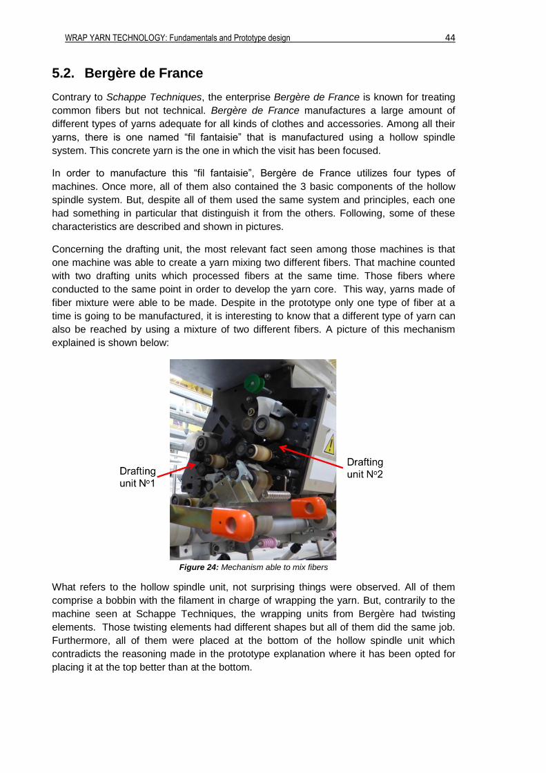
Concerning the drafting unit, the most relevant fact seen among those machines is that
one machine was able to create a yarn mixing two different fibers. That machine counted
with two drafting units which processed fibers at the same time. Those fibers where
conducted to the same point in order to develop the yarn core. This way, yarns made of
fiber mixture were able to be made. Despite in the prototype only one type of fiber at a
time is going to be manufactured, it is interesting to know that a different type of yarn can
also be reached by using a mixture of two different fibers. A picture of this mechanism
explained is shown below:
Figure 24: Mechanism able to mix fibers
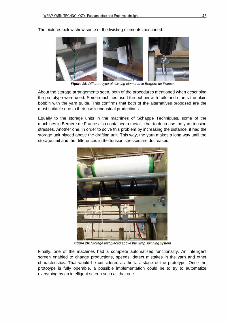
What refers to the hollow spindle unit, not surprising things were observed. All of them
comprise a bobbin with the filament in charge of wrapping the yarn. But, contrarily to the
machine seen at Schappe Techniques, the wrapping units from Bergère had twisting
elements. Those twisting elements had different shapes but all of them did the same job.
Furthermore, all of them were placed at the bottom of the hollow spindle unit which
contradicts the reasoning made in the prototype explanation where it has been opted for
placing it at the top better than at the bottom.
WRAP YARN TECHNOLOGY: Fundamentals and Prototype design 45
The pictures below show some of the twisting elements mentioned:
Figure 25: Different type of twisting elements at Bergère de France
About the storage arrangements seen, both of the procedures mentioned when describing
the prototype were used. Some machines used the bobbin with rails and others the plain
bobbin with the yarn guide. This confirms that both of the alternatives proposed are the
most suitable due to their use in industrial productions.
Equally to the storage units in the machines of Schappe Techniques, some of the
machines in Bergère de France also contained a metallic bar to decrease the yarn tension
stresses. Another one, in order to solve this problem by increasing the distance, it had the
storage unit placed above the drafting unit. This way, the yarn makes a long way until the
storage unit and the differences in the tension stresses are decreased.
Figure 26: Storage unit placed above the wrap spinning system
Finally, one of the machines had a complete automatized functionality. An intelligent
screen enabled to change productions, speeds, detect mistakes in the yarn and other
characteristics. That would be considered as the last stage of the prototype. Once the
prototype is fully operable, a possible implementation could be to try to automatize
everything by an intelligent screen such as that one.
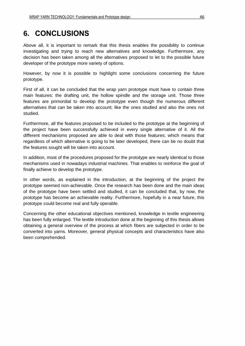
WRAP YARN TECHNOLOGY: Fundamentals and Prototype design 46
6. CONCLUSIONS
Above all, it is important to remark that this thesis enables the possibility to continue
investigating and trying to reach new alternatives and knowledge. Furthermore, any
decision has been taken among all the alternatives proposed to let to the possible future
developer of the prototype more variety of options.
However, by now it is possible to highlight some conclusions concerning the future
prototype.
First of all, it can be concluded that the wrap yarn prototype must have to contain three
main features: the drafting unit, the hollow spindle and the storage unit. Those three
features are primordial to develop the prototype even though the numerous different
alternatives that can be taken into account; like the ones studied and also the ones not
studied.
Furthermore, all the features proposed to be included to the prototype at the beginning of
the project have been successfully achieved in every single alternative of it. All the
different mechanisms proposed are able to deal with those features; which means that
regardless of which alternative is going to be later developed, there can be no doubt that
the features sought will be taken into account.
In addition, most of the procedures proposed for the prototype are nearly identical to those
mechanisms used in nowadays industrial machines. That enables to reinforce the goal of
finally achieve to develop the prototype.
In other words, as explained in the introduction, at the beginning of the project the
prototype seemed non-achievable. Once the research has been done and the main ideas
of the prototype have been settled and studied, it can be concluded that, by now, the
prototype has become an achievable reality. Furthermore, hopefully in a near future, this
prototype could become real and fully operable.
Concerning the other educational objectives mentioned, knowledge in textile engineering
has been fully enlarged. The textile introduction done at the beginning of this thesis allows
obtaining a general overview of the process at which fibers are subjected in order to be
converted into yarns. Moreover, general physical concepts and characteristics have also
been comprehended.

WRAP YARN TECHNOLOGY: Fundamentals and Prototype design 47
7. ANNEX
7.1. False Twist
There are some stages related with the yarn producing that need to be false-twisted.
Apply a twist to a fiber strand increases the fiber tenacity and gives them cohesion. That
cohesion is, above all, significant in short fibers because, without it, fibers tend to separate
and the fiber mass would break regularly. In the field of long fibers, this twist in not that
important by reason of the own length of the fibers that make them stabilize and do not
break.
Even though a twist is needed to give some cohesion to fibers, the torque provided by that
twist is not useful and so, it is need to make it disappear. That is the reason why the false-
twist method is applied.
This particular method consists on the following:
When a ribbon is nipped by two extremes and a twist, by angular speed W [rev/min], is
applied in some point in between those two extremes, it appears a torque in both sides of
the point where the twist is applied (one part of the ribbon twists in one way and the other
twists in the opposite way). If the ribbon has no speed, i.e. it is static, the torsion maintains
itself. This torsion is referred to as stable torsion. But, if the ribbon is given a certain
speed, the torsion of the inferior part of the ribbon (B) is going to disappear after passing a
certain time (virtual torsion), whereas the superior part of the ribbon (A) is going to
maintain the torsion (stable torsion).
Thus, the non-needed torsion (TB) disappears while the needed torsion (TA) is maintained.
Figure 27: False-twist concepts
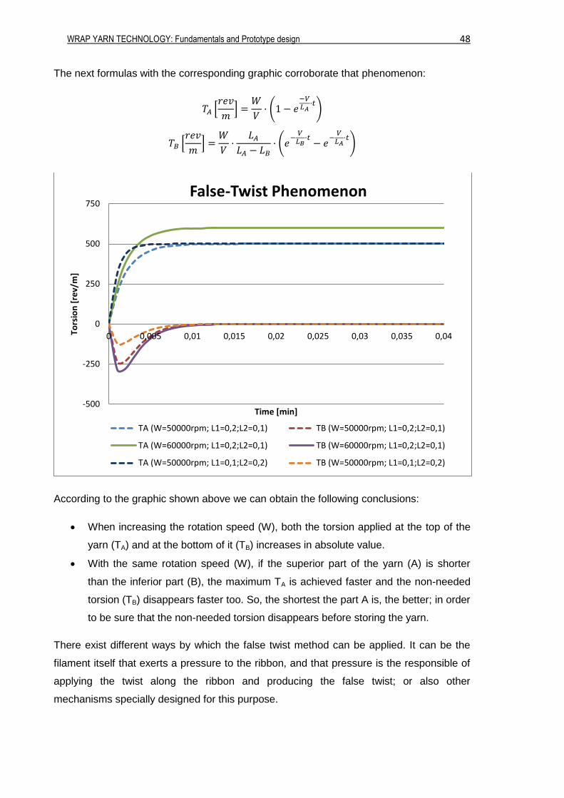
WRAP YARN TECHNOLOGY: Fundamentals and Prototype design 48
The next formulas with the corresponding graphic corroborate that phenomenon:
𝑇𝐴 [𝑟𝑒𝑣
𝑚] =
𝑊
𝑉· (1 − 𝑒
−𝑉𝐿𝐴
·𝑡)
𝑇𝐵 [𝑟𝑒𝑣
𝑚] =
𝑊
𝑉·
𝐿𝐴
𝐿𝐴 − 𝐿𝐵· (𝑒
−𝑉
𝐿𝐵·𝑡
− 𝑒−
𝑉𝐿𝐴
·𝑡)
According to the graphic shown above we can obtain the following conclusions:
When increasing the rotation speed (W), both the torsion applied at the top of the
yarn (TA) and at the bottom of it (TB) increases in absolute value.
With the same rotation speed (W), if the superior part of the yarn (A) is shorter
than the inferior part (B), the maximum TA is achieved faster and the non-needed
torsion (TB) disappears faster too. So, the shortest the part A is, the better; in order
to be sure that the non-needed torsion disappears before storing the yarn.
There exist different ways by which the false twist method can be applied. It can be the
filament itself that exerts a pressure to the ribbon, and that pressure is the responsible of
applying the twist along the ribbon and producing the false twist; or also other
mechanisms specially designed for this purpose.
-500
-250
0
250
500
750
0 0,005 0,01 0,015 0,02 0,025 0,03 0,035 0,04Tors
ion
[re
v/m
]
Time [min]
False-Twist Phenomenon
TA (W=50000rpm; L1=0,2;L2=0,1) TB (W=50000rpm; L1=0,2;L2=0,1)
TA (W=60000rpm; L1=0,2;L2=0,1) TB (W=60000rpm; L1=0,2;L2=0,1)
TA (W=50000rpm; L1=0,1;L2=0,2) TB (W=50000rpm; L1=0,1;L2=0,2)
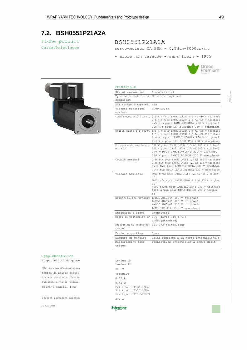
WRAP YARN TECHNOLOGY: Fundamentals and Prototype design 49
7.2. BSH0551P21A2A
Fiche produit Caractéristiques
Complémentaires Compatibilité de gamme [Us] tension d'alimentation Nombre de phases réseau Courant continu à l'arrêt Puissance continue maximum Courant maximal Irms Courant permanent maximum
26 mai 2015
BSH0551P21A2A servo-moteur CA BSH - 0,5N.m-8000tr/mn
- arbre non taraudé - sans frein - IP65
Principale Statut commercial Commercialisé
document.
Type de produit ou de Moteur autopiloté
présent
composant
Nom abrégé d'appareil BSH
Le présent document comprend des descriptions générales et/ou des caractéristiques techniques générales sur la performance des produits auxquels il se réfère.Leprésentdocumentnepeutêtreutilisépourdéterminerl'aptitudeoulafiabilitédecesproduitspourdesapplicationsutilisateurspécifiquesetn'estpasdestinéà se substituer à cette détermination.Ilappartientàchaqueutilisateurouintégrateurderéaliser,soussapropreresponsabilité,l'analysederisquescomplèteetappropriée,d'évaluerettesterlesproduitsdanslecontextedeleurl'application ou utilisation spécifique.NilasociétéSchneiderElectricIndustriesSAS,niaucunedesesfilialesousociétésdanslesquelleselledétientuneparticipation,nepeutêtretenuepourresponsabledelamauvaiseutilisationdel'informationcontenuedansle
Vitesse mécanique 9000 Tr/mn
maximum
Couple continu à l'arrêt 0.5 N.m pour LXM32.U60N4 1.5 Aà 480 V triphasé
0.5 N.m pour LXM32.U60N4 1.5 Aà 400 V triphasé
0.5 N.m pour LXM15LU60N4à 230 V triphasé
0.5 N.m pour LXM15LD13M3à 230 V monophasé
Couple crête à l’arrêt 1.5 N.m pour LXM32.U60N4 1.5 Aà 480 V triphasé
1.5 N.m pour LXM32.U60N4 1.5 Aà 400 V triphasé
1.4 N.m pour LXM15LU60N4à 230 V triphasé
1.4 N.m pour LXM15LD13M3à 230 V monophasé
Puissance de sortie no- 300 W pour LXM32.U60N4 1.5 Aà 480 V triphasé
minale 300 W pour LXM32.U60N4 1.5 Aà 400 V triphasé
170 W pour LXM15LU60N4à 230 V triphasé
170 W pour LXM15LD13M3à 230 V monophasé
Couple nominal 0.48 N.m pour LXM32.U60N4 1.5 Aà 480 V triphasé
0.48 N.m pour LXM32.U60N4 1.5 Aà 400 V triphasé
0.46 N.m pour LXM15LU60N4à 230 V triphasé
0.46 N.m pour LXM15LD13M3à 230 V monophasé
Vitesse nominale 6000 tr/mn pour LXM32.U60N4 1.5 Aà 480 V tripha-
sé
6000 tr/min pour LXM32.U60N4 1.5 Aà 400 V tripha-
sé
4000 tr/mn pour LXM15LU60N4à 230 V triphasé
4000 tr/min pour LXM15LD13M3à 230 V monopha-
sé
Compatibilité produit LXM32.U60N4à 480 V triphasé
LXM32.U60N4à 400 V triphasé
LXM15LU60N4à 230 V triphasé
LXM15LD13M3à 230 V monophasé
Extrémité d'arbre Inexploité
Degré de protection IP IP67 (avec kit IP67)
IP65 (standard)
Résolution du retour vi- 131 072 points/tour
tesse
Frein de parking Sans
Support de montage Bride conforme à la norme internationale
Raccordement élec- Connecteurs orientables à angle droit
trique
Lexium 15
Lexium 32
480 V
Triphasé
0.73 A
0.45 W
2.9 A pour LXM32.U60N4
3.5 A pour LXM15LU60N4
3.5 A pour LXM15LD13M3
2.9 A
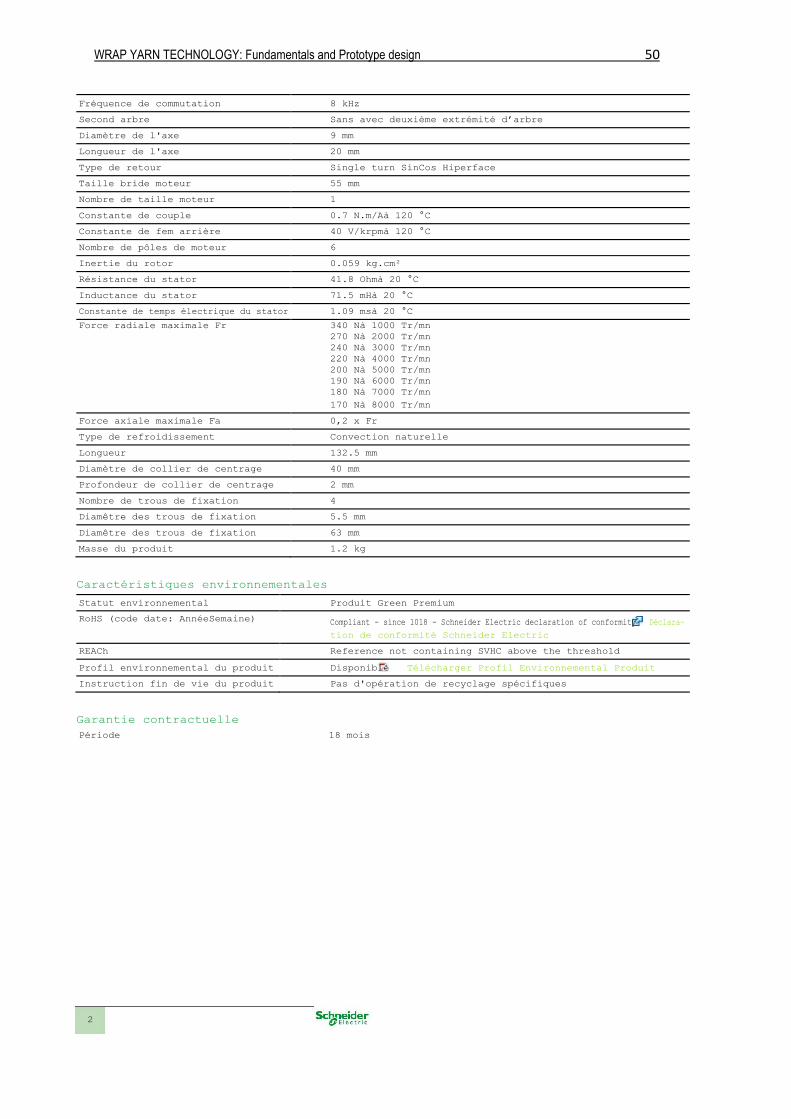
WRAP YARN TECHNOLOGY: Fundamentals and Prototype design 50
Fréquence de commutation 8 kHz
Second arbre Sans avec deuxième extrémité d’arbre
Diamètre de l'axe 9 mm
Longueur de l'axe 20 mm
Type de retour Single turn SinCos Hiperface
Taille bride moteur 55 mm
Nombre de taille moteur 1
Constante de couple 0.7 N.m/Aà 120 °C
Constante de fem arrière 40 V/krpmà 120 °C
Nombre de pôles de moteur 6
Inertie du rotor 0.059 kg.cm²
Résistance du stator 41.8 Ohmà 20 °C
Inductance du stator 71.5 mHà 20 °C
Constante de temps électrique du stator 1.09 msà 20 °C
Force radiale maximale Fr 340 Nà 1000 Tr/mn 270 Nà 2000 Tr/mn 240 Nà 3000 Tr/mn 220 Nà 4000 Tr/mn 200 Nà 5000 Tr/mn 190 Nà 6000 Tr/mn 180 Nà 7000 Tr/mn 170 Nà 8000 Tr/mn
Force axiale maximale Fa 0,2 x Fr
Type de refroidissement Convection naturelle
Longueur 132.5 mm
Diamètre de collier de centrage 40 mm
Profondeur de collier de centrage 2 mm
Nombre de trous de fixation 4
Diamêtre des trous de fixation 5.5 mm
Diamêtre des trous de fixation 63 mm
Masse du produit 1.2 kg
Caractéristiques environnementales Statut environnemental Produit Green Premium
RoHS (code date: AnnéeSemaine) Compliant - since 1018 - Schneider Electric declaration of conformity Déclara-
tion de conformité Schneider Electric
REACh Reference not containing SVHC above the threshold
Profil environnemental du produit Disponible Télécharger Profil Environnemental Produit
Instruction fin de vie du produit Pas d'opération de recyclage spécifiques
Garantie contractuelle Période 18 mois
2
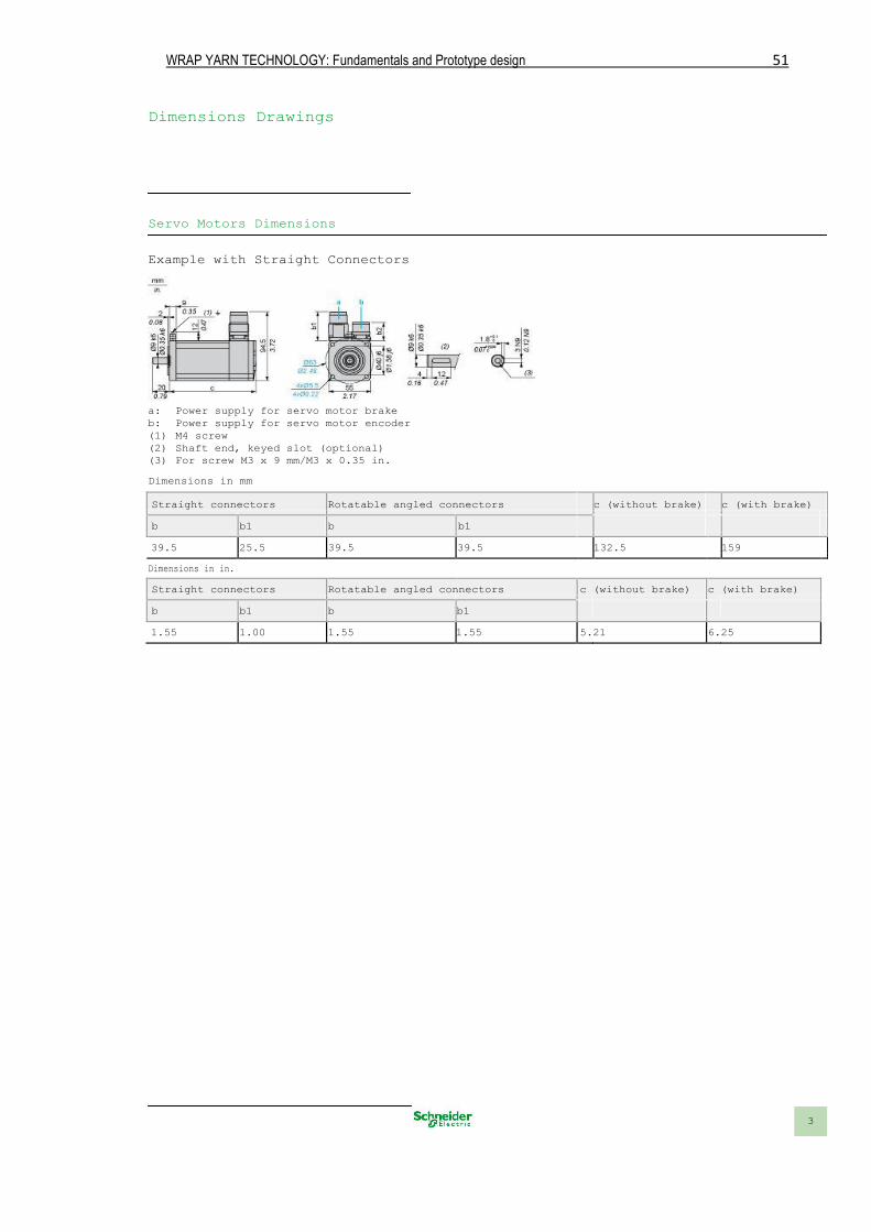
WRAP YARN TECHNOLOGY: Fundamentals and Prototype design 51
Dimensions Drawings
Servo Motors Dimensions
Example with Straight Connectors
a: Power supply for servo motor brake b: Power supply for servo motor encoder (1) M4 screw (2) Shaft end, keyed slot (optional) (3) For screw M3 x 9 mm/M3 x 0.35 in. Dimensions in mm Straight connectors Rotatable angled connectors c (without brake) c (with brake)
b b1 b b1
39.5 25.5 39.5 39.5 132.5 159
Dimensions in in.
Straight connectors Rotatable angled connectors c (without brake) c (with brake)
b b1 b b1
1.55 1.00 1.55 1.55 5.21 6.25
3
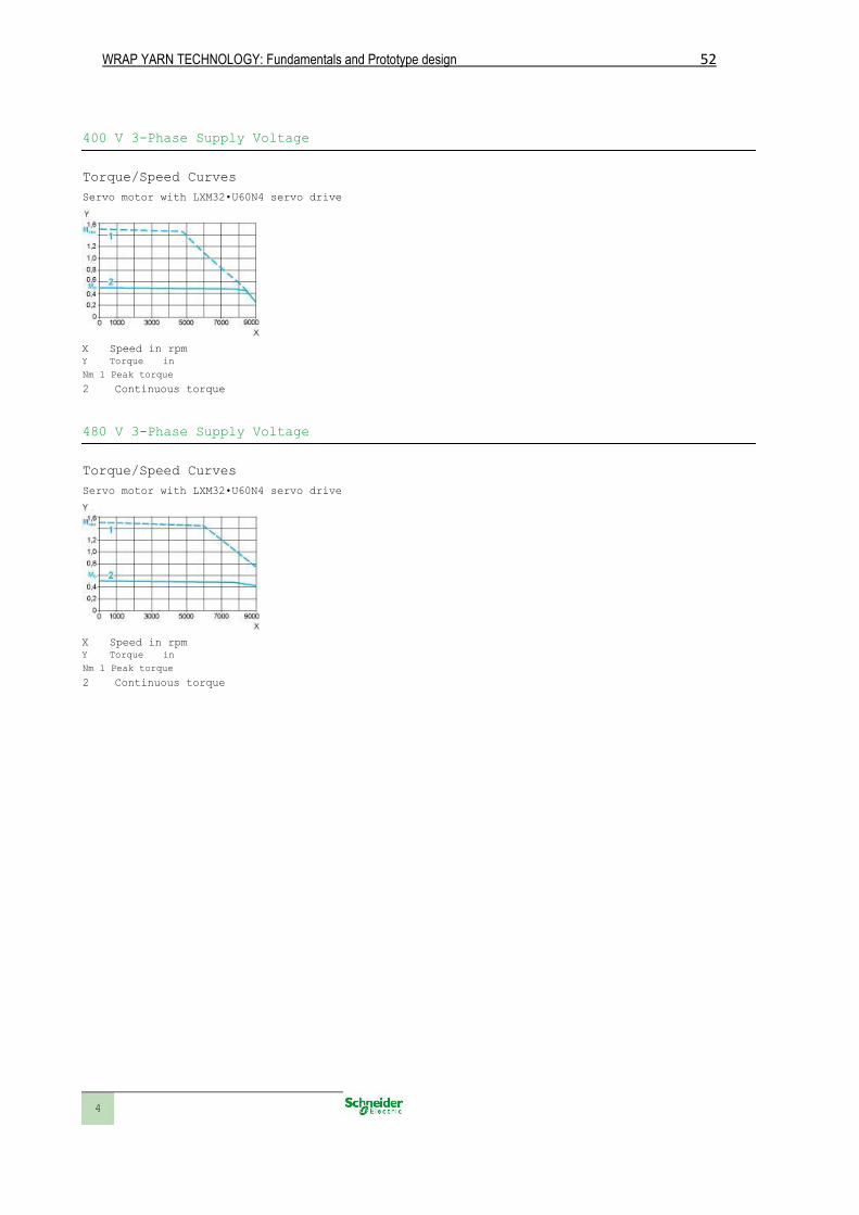
WRAP YARN TECHNOLOGY: Fundamentals and Prototype design 52
400 V 3-Phase Supply Voltage
Torque/Speed Curves Servo motor with LXM32•U60N4 servo drive
X Speed in rpm Y Torque in
Nm 1 Peak torque
2 Continuous torque
480 V 3-Phase Supply Voltage
Torque/Speed Curves Servo motor with LXM32•U60N4 servo drive
X Speed in rpm Y Torque in
Nm 1 Peak torque
2 Continuous torque
4
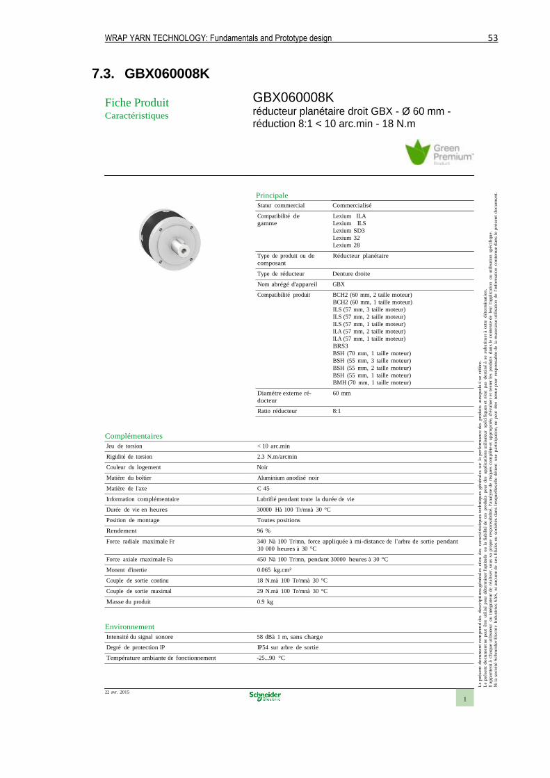
WRAP YARN TECHNOLOGY: Fundamentals and Prototype design 53
7.3. GBX060008K
Le
pré
sen
t d
ocum
en
t co
mpre
nd d
es
desc
rip
tio
ns
généra
les
et/o
u
des
cara
cté
rist
iqu
es
tech
niq
ues
gén
éra
les
sur
la p
erf
orm
ance d
es
pro
du
its
au
xq
uels
il se r
éfè
re.
Le
pré
sen
t d
ocu
men
t n
e p
eut
être
u
tili
sé p
ou
r déte
rmin
er
l'ap
titu
de
ou
la
fiab
ilit
é d
e ce
s p
rodu
its
po
ur
des
ap
pli
cati
on
s u
tili
sate
ur
sp
écif
iqu
es
et n
'est
p
as
dest
iné à
se s
ub
stit
uer
à ce
tte
déte
rmin
ati
on
.
Il a
ppart
ient
à ch
aq
ue u
tili
sate
ur
ou
inté
gra
teu
r d
e ré
ali
ser,
so
us s
a p
rop
re
resp
on
sab
ilit
é,
l'analy
se d
e ri
squ
es
co
mp
lète
et
ap
pro
pri
ée,
d'é
valu
er
et t
este
r le
s p
rod
uit
s d
an
s l
e co
nte
xte
de l
eu
r l'ap
pli
cat
ion
o
u u
tili
sati
on
sp
écif
iqu
e.
Ni
la s
ocié
té S
ch
neid
er
Ele
ctri
c I
nd
ust
ries
SA
S,
ni au
cu
ne d
e ses f
ilia
les
ou
so
cié
tés d
an
s l
esq
uell
es e
lle d
étie
nt
un
e part
icip
ati
on,
ne
peu
t êt
re te
nu
e p
ou
r re
sp
on
sab
le d
e la
mau
vais
e u
tili
sati
on
de
l'in
form
ati
on c
on
ten
ue d
an
s l
e p
rése
nt
do
cu
men
t.
Fiche Produit Caractéristiques
Principale
Statut commercial Commercialisé
Compatibilité de
gamme
Type de produit ou de
composant
Lexium ILA
Lexium ILS
Lexium SD3
Lexium 32
Lexium 28
Réducteur planétaire
Type de réducteur Denture droite
Nom abrégé d'appareil GBX
Compatibilité produit BCH2 (60 mm, 2 taille moteur)
BCH2 (60 mm, 1 taille moteur)
ILS (57 mm, 3 taille moteur)
ILS (57 mm, 2 taille moteur)
ILS (57 mm, 1 taille moteur)
ILA (57 mm, 2 taille moteur)
ILA (57 mm, 1 taille moteur)
BRS3
BSH (70 mm, 1 taille moteur)
BSH (55 mm, 3 taille moteur)
BSH (55 mm, 2 taille moteur)
BSH (55 mm, 1 taille moteur)
BMH (70 mm, 1 taille moteur)
Diamétre externe ré-
ducteur
60 mm
Ratio réducteur 8:1
Complémentaires
Jeu de torsion < 10 arc.min
Rigidité de torsion 2.3 N.m/arcmin
Couleur du logement Noir
Matière du boîtier Aluminium anodisé noir
Matière de l'axe C 45
Information complémentaire Lubrifié pendant toute la durée de vie
Durée de vie en heures 30000 Hà 100 Tr/mnà 30 °C
Position de montage Toutes positions
Rendement 96 %
Force radiale maximale Fr 340 Nà 100 Tr/mn, force appliquée à mi-distance de l’arbre de sortie pendant
30 000 heures à 30 °C
Force axiale maximale Fa 450 Nà 100 Tr/mn, pendant 30000 heures à 30 °C
Monent d'inertie 0.065 kg.cm²
Couple de sortie continu 18 N.mà 100 Tr/mnà 30 °C
Couple de sortie maximal 29 N.mà 100 Tr/mnà 30 °C
Masse du produit 0.9 kg
Environnement
Intensité du signal sonore 58 dBà 1 m, sans charge
Degré de protection IP IP54 sur arbre de sortie
Température ambiante de fonctionnement -25...90 °C
22 avr. 2015
1
GBX060008K réducteur planétaire droit GBX - Ø 60 mm - réduction 8:1 < 10 arc.min - 18 N.m

WRAP YARN TECHNOLOGY: Fundamentals and Prototype design 54
Caractéristiques environnementales
Statut environnemental Produit Green Premium
RoHS (code date: AnnéeSemaine) Compliant - since 1129 - Schneider Electric declaration of conformity Déclara-
tion de conformité Schneider Electric
REACh Reference not containing SVHC above the threshold
Profil environnemental du produit Disponible Télécharger Profil Environnemental Produit
Instruction fin de vie du produit Pas d'opération de recyclage spécifiques
Garantie contractuelle
Période 18 mois
2
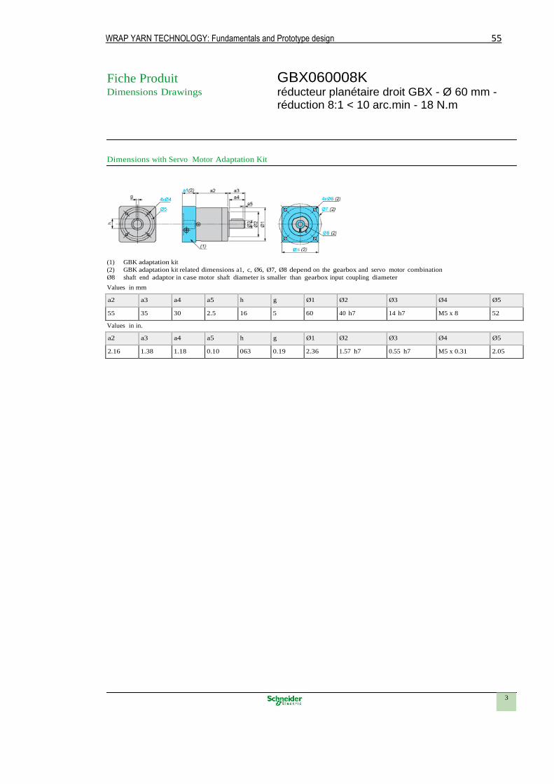
WRAP YARN TECHNOLOGY: Fundamentals and Prototype design 55
Fiche Produit Dimensions Drawings
Dimensions with Servo Motor Adaptation Kit
(1) GBK adaptation kit
(2) GBK adaptation kit related dimensions a1, c, Ø6, Ø7, Ø8 depend on the gearbox and servo motor combination
Ø8 shaft end adaptor in case motor shaft diameter is smaller than gearbox input coupling diameter
Values in mm
a2 a3 a4 a5 h g Ø1 Ø2 Ø3 Ø4 Ø5
55 35 30 2.5 16 5 60 40 h7 14 h7 M5 x 8 52
Values in in.
a2 a3 a4 a5 h g Ø1 Ø2 Ø3 Ø4 Ø5
2.16 1.38 1.18 0.10 063 0.19 2.36 1.57 h7 0.55 h7 M5 x 0.31 2.05
3
GBX060008K réducteur planétaire droit GBX - Ø 60 mm - réduction 8:1 < 10 arc.min - 18 N.m
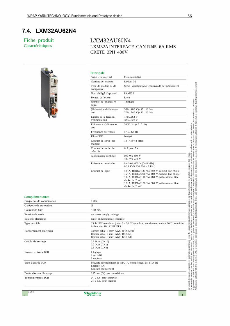
WRAP YARN TECHNOLOGY: Fundamentals and Prototype design 56
7.4. LXM32AU62N4
26 mai 2015
1 1
Le
pré
sen
t d
ocum
en
t co
mpre
nd d
es
desc
rip
tio
ns
généra
les
et/o
u des
cara
cté
rist
iqu
es
tech
niq
ues
gén
éra
les
sur
la p
erf
orm
ance d
es
pro
duit
s a
ux
qu
els
il se
réfè
re.
Le
pré
sen
t d
ocu
men
t ne
peu
t êt
re
uti
lisé
pour
déte
rmin
er
l'apti
tude
ou l
a fi
abil
ité
de
ces
pro
duit
s p
our
des
ap
pli
cati
on
s uti
lisa
teur
sp
écif
iqu
es
et n
'est
pas
d
est
iné à
se s
ub
stit
uer
à ce
tte
déte
rmin
ati
on
.
Il a
ppart
ient
à ch
aq
ue u
tili
sate
ur
ou i
nté
gra
teu
r de
réali
ser,
so
us
sa p
ropre
re
spon
sab
ilit
é,
l'analy
se d
e ri
squ
es
co
mp
lète
et
ap
pro
pri
ée,
d'é
valu
er
et t
est
er
les
pro
duit
s d
an
s l
e co
nte
xte
de
leur
l'appli
cati
on
ou u
tili
sati
on
sp
écif
iqu
e.
Ni la
so
cié
té S
ch
neid
er
Ele
ctri
c In
du
stri
es
SA
S,
ni au
cu
ne d
e ses f
ilia
les
ou s
ocié
tés
dan
s le
squ
ell
es e
lle
dét
ient
une
par
tici
pat
ion,
ne
peu
t êt
re te
nu
e p
our
resp
on
sab
le d
e la
mau
vais
e u
tili
sati
on
de
l'info
rmat
ion c
on
ten
ue d
an
s le
pré
sen
t d
ocu
men
t.
Fiche produit Caractéristiques
LXM32AU60N4 LXM32A INTERFACE CAN RJ45 6A RMS
CRETE 3PH 480V
Principale
Statut commercial Commercialisé
Gamme de produits Lexium 32
Type de produit ou de
composant
Servo variateur pour commande de mouvement
Nom abrégé d'appareil LXM32A
Format du lecteur Livre
Nombre de phases ré-
seau
[Us] tension d'alimenta-
tion
Limites de la tension
d'alimentation
Fréquence d'alimenta-
tion
Triphasé
380...480 V (- 15...10 %)
200...240 V (- 15...10 %)
170...264 V
323...528 V
50/60 Hz (- 5...5 %)
Fréquence du réseau 47,5...63 Hz
Filtre CEM Intégré
Courant de sortie per-
manent
Courant de sortie de
crête 3s
1.8 A (f = 8 kHz)
6 A pour 5 s
Alimentation continue 800 Wà 400 V
400 Wà 230 V
Puissance nominale 0.4 kWà 400 V (f = 8 kHz)
0.35 kWà 230 V (f = 8 kHz)
Courant de ligne 1.8 A, THDI of 187 %à 380 V, without line choke
1.2 A, THDI of 201 %à 480 V, without line choke
1.6 A, THDI of 116 %à 480 V, with external line
choke de 2 mH
1.9 A, THDI of 106 %à 380 V, with external line
choke de 2 mH
Complémentaires
Fréquence de commutation 8 kHz
Catégorie de surtension III
Courant de fuite < 30 mA
Tension de sortie <= power supply voltage
Isolation électrique Entre alimentation et contrôle
Type de câble Câble IEC monobrin (pour θ = 50 °C) matériau conducteur: cuivre 90°C ,matériau
isolant des fils: XLPE/EPR
Raccordement électrique Bornier câble 5 mm² AWG 10 (CN10)
Bornier câble 5 mm² AWG 10 (CN1)
Bornier câble 3 mm² AWG 12 (CN8)
Couple de serrage 0.7 N.m (CN10)
0.7 N.m (CN1)
0.5 N.m (CN8)
Nombre entrées TOR 4 logique
2 sécurité
1 capture
Type d'entrée TOR Sécurité (complément de STO_A, complément de STO_B)
Logique (DI)
Capture (capuchon)
Durée d'échantillonnage 0.25 ms (DI) pour numérique
Tension entrées TOR 24 V c.c. pour sécurité
24 V c.c. pour logique
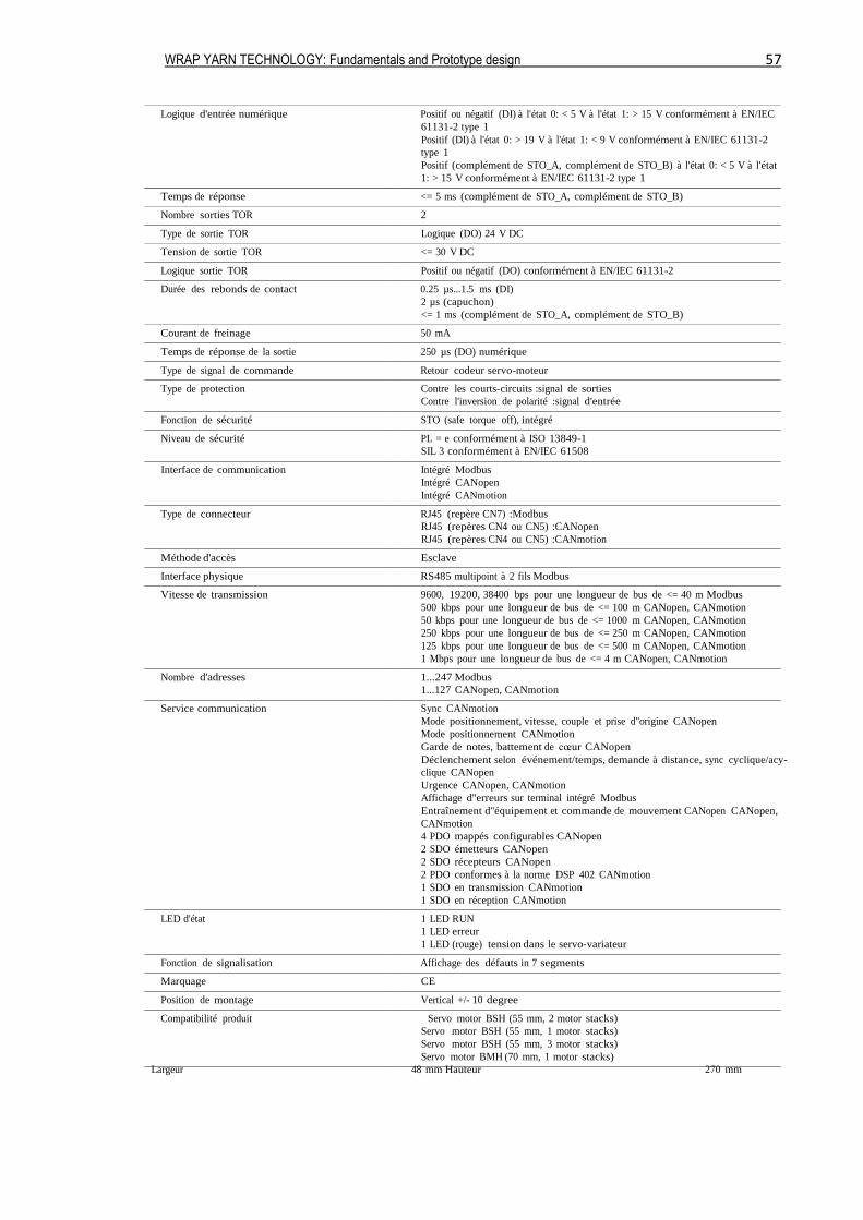
WRAP YARN TECHNOLOGY: Fundamentals and Prototype design 57
Logique d'entrée numérique Positif ou négatif (DI) à l'état 0: < 5 V à l'état 1: > 15 V conformément à EN/IEC
61131-2 type 1
Positif (DI) à l'état 0: > 19 V à l'état 1: < 9 V conformément à EN/IEC 61131-2
type 1
Positif (complément de STO_A, complément de STO_B) à l'état 0: < 5 V à l'état
1: > 15 V conformément à EN/IEC 61131-2 type 1
Temps de réponse <= 5 ms (complément de STO_A, complément de STO_B)
Nombre sorties TOR 2
Type de sortie TOR Logique (DO) 24 V DC
Tension de sortie TOR <= 30 V DC
Logique sortie TOR Positif ou négatif (DO) conformément à EN/IEC 61131-2
Durée des rebonds de contact 0.25 µs...1.5 ms (DI)
2 µs (capuchon)
<= 1 ms (complément de STO_A, complément de STO_B)
Courant de freinage 50 mA
Temps de réponse de la sortie 250 µs (DO) numérique
Type de signal de commande Retour codeur servo-moteur
Type de protection Contre les courts-circuits :signal de sorties
Contre l'inversion de polarité :signal d'entrée
Fonction de sécurité STO (safe torque off), intégré
Niveau de sécurité PL = e conformément à ISO 13849-1
SIL 3 conformément à EN/IEC 61508
Interface de communication Intégré Modbus
Intégré CANopen
Intégré CANmotion
Type de connecteur RJ45 (repère CN7) :Modbus
RJ45 (repères CN4 ou CN5) :CANopen
RJ45 (repères CN4 ou CN5) :CANmotion
Méthode d'accès Esclave
Interface physique RS485 multipoint à 2 fils Modbus
Vitesse de transmission 9600, 19200, 38400 bps pour une longueur de bus de <= 40 m Modbus
500 kbps pour une longueur de bus de <= 100 m CANopen, CANmotion
50 kbps pour une longueur de bus de <= 1000 m CANopen, CANmotion
250 kbps pour une longueur de bus de <= 250 m CANopen, CANmotion
125 kbps pour une longueur de bus de <= 500 m CANopen, CANmotion
1 Mbps pour une longueur de bus de <= 4 m CANopen, CANmotion
Nombre d'adresses 1...247 Modbus
1...127 CANopen, CANmotion
Service communication Sync CANmotion
Mode positionnement, vitesse, couple et prise d''origine CANopen
Mode positionnement CANmotion
Garde de notes, battement de cœur CANopen
Déclenchement selon événement/temps, demande à distance, sync cyclique/acy-
clique CANopen
Urgence CANopen, CANmotion
Affichage d''erreurs sur terminal intégré Modbus
Entraînement d''équipement et commande de mouvement CANopen CANopen,
CANmotion
4 PDO mappés configurables CANopen
2 SDO émetteurs CANopen
2 SDO récepteurs CANopen
2 PDO conformes à la norme DSP 402 CANmotion
1 SDO en transmission CANmotion
1 SDO en réception CANmotion
LED d'état 1 LED RUN
1 LED erreur
1 LED (rouge) tension dans le servo-variateur
Fonction de signalisation Affichage des défauts in 7 segments
Marquage CE
Position de montage Vertical +/- 10 degree
Compatibilité produit Servo motor BSH (55 mm, 2 motor stacks)
Servo motor BSH (55 mm, 1 motor stacks)
Servo motor BSH (55 mm, 3 motor stacks)
Servo motor BMH (70 mm, 1 motor stacks)
Largeur 48 mm Hauteur 270 mm
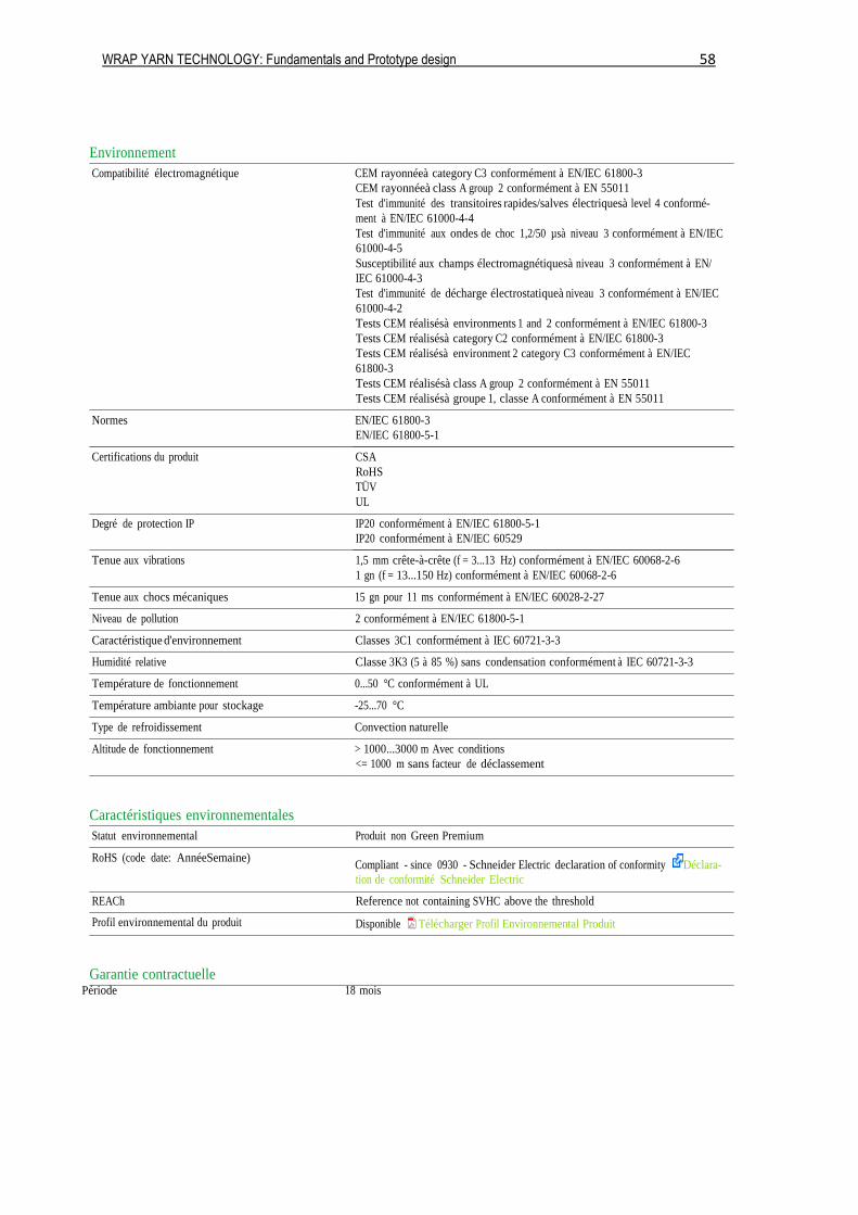
WRAP YARN TECHNOLOGY: Fundamentals and Prototype design 58
Environnement
Compatibilité électromagnétique CEM rayonnéeà category C3 conformément à EN/IEC 61800-3
CEM rayonnéeà class A group 2 conformément à EN 55011
Test d'immunité des transitoires rapides/salves électriquesà level 4 conformé-
ment à EN/IEC 61000-4-4
Test d'immunité aux ondes de choc 1,2/50 µsà niveau 3 conformément à EN/IEC
61000-4-5
Susceptibilité aux champs électromagnétiquesà niveau 3 conformément à EN/
IEC 61000-4-3
Test d'immunité de décharge électrostatiqueà niveau 3 conformément à EN/IEC
61000-4-2
Tests CEM réalisésà environments 1 and 2 conformément à EN/IEC 61800-3
Tests CEM réalisésà category C2 conformément à EN/IEC 61800-3
Tests CEM réalisésà environment 2 category C3 conformément à EN/IEC
61800-3
Tests CEM réalisésà class A group 2 conformément à EN 55011
Tests CEM réalisésà groupe 1, classe A conformément à EN 55011
Normes EN/IEC 61800-3
EN/IEC 61800-5-1
Certifications du produit CSA
RoHS
TÜV
UL
Degré de protection IP IP20 conformément à EN/IEC 61800-5-1
IP20 conformément à EN/IEC 60529
Tenue aux vibrations 1,5 mm crête-à-crête (f = 3...13 Hz) conformément à EN/IEC 60068-2-6
1 gn (f = 13...150 Hz) conformément à EN/IEC 60068-2-6
Tenue aux chocs mécaniques 15 gn pour 11 ms conformément à EN/IEC 60028-2-27
Niveau de pollution 2 conformément à EN/IEC 61800-5-1
Caractéristique d'environnement Classes 3C1 conformément à IEC 60721-3-3
Humidité relative Classe 3K3 (5 à 85 %) sans condensation conformément à IEC 60721-3-3
Température de fonctionnement 0...50 °C conformément à UL
Température ambiante pour stockage -25...70 °C
Type de refroidissement Convection naturelle
Altitude de fonctionnement > 1000...3000 m Avec conditions
<= 1000 m sans facteur de déclassement
Caractéristiques environnementales
Statut environnemental Produit non Green Premium
RoHS (code date: AnnéeSemaine) Compliant - since 0930 - Schneider Electric declaration of conformity Déclara-
tion de conformité Schneider Electric
REACh Reference not containing SVHC above the threshold
Profil environnemental du produit Disponible Télécharger Profil Environnemental Produit
Garantie contractuelle Période 18 mois

WRAP YARN TECHNOLOGY: Fundamentals and Prototype design 59
Dimensions
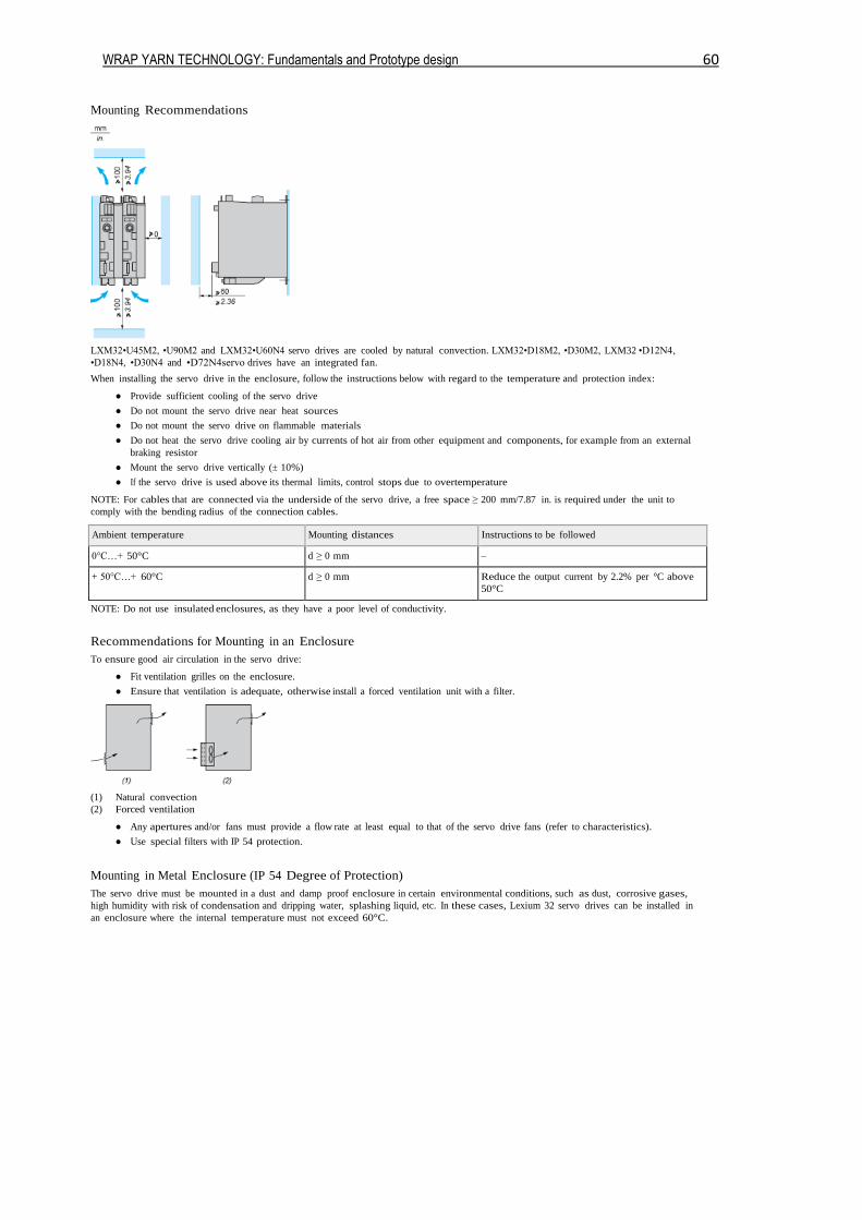
WRAP YARN TECHNOLOGY: Fundamentals and Prototype design 60
Mounting Recommendations
LXM32•U45M2, •U90M2 and LXM32•U60N4 servo drives are cooled by natural convection. LXM32•D18M2, •D30M2, LXM32 •D12N4,
•D18N4, •D30N4 and •D72N4servo drives have an integrated fan.
When installing the servo drive in the enclosure, follow the instructions below with regard to the temperature and protection index:
● Provide sufficient cooling of the servo drive
● Do not mount the servo drive near heat sources
● Do not mount the servo drive on flammable materials
● Do not heat the servo drive cooling air by currents of hot air from other equipment and components, for example from an external
braking resistor
● Mount the servo drive vertically (± 10%)
● If the servo drive is used above its thermal limits, control stops due to overtemperature
NOTE: For cables that are connected via the underside of the servo drive, a free space ≥ 200 mm/7.87 in. is required under the unit to
comply with the bending radius of the connection cables.
Ambient temperature Mounting distances Instructions to be followed
0°C…+ 50°C d ≥ 0 mm –
+ 50°C…+ 60°C d ≥ 0 mm Reduce the output current by 2.2% per °C above
50°C
NOTE: Do not use insulated enclosures, as they have a poor level of conductivity.
Recommendations for Mounting in an Enclosure
To ensure good air circulation in the servo drive:
● Fit ventilation grilles on the enclosure.
● Ensure that ventilation is adequate, otherwise install a forced ventilation unit with a filter.
(1) Natural convection
(2) Forced ventilation
● Any apertures and/or fans must provide a flow rate at least equal to that of the servo drive fans (refer to characteristics).
● Use special filters with IP 54 protection.
Mounting in Metal Enclosure (IP 54 Degree of Protection)
The servo drive must be mounted in a dust and damp proof enclosure in certain environmental conditions, such as dust, corrosive gases,
high humidity with risk of condensation and dripping water, splashing liquid, etc. In these cases, Lexium 32 servo drives can be installed in
an enclosure where the internal temperature must not exceed 60°C.
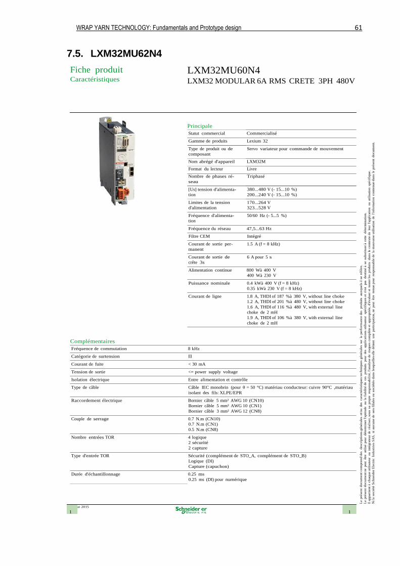
WRAP YARN TECHNOLOGY: Fundamentals and Prototype design 61
7.5. LXM32MU62N4
26 mai 2015
1 1
Le
pré
sen
t d
ocum
en
t co
mpre
nd d
es
desc
rip
tio
ns
généra
les
et/o
u des
cara
cté
rist
iqu
es
tech
niq
ues
gén
éra
les
sur
la p
erf
orm
ance d
es
pro
duit
s a
ux
qu
els
il se
réfè
re.
Le
pré
sen
t d
ocu
men
t ne
peu
t êt
re
uti
lisé
pour
déte
rmin
er
l'apti
tude
ou l
a fi
abil
ité
de
ces
pro
duit
s p
our
des
ap
pli
cati
on
s uti
lisa
teur
sp
écif
iqu
es
et n
'est
pas
d
est
iné à
se s
ub
stit
uer
à ce
tte
déte
rmin
ati
on
.
Il a
ppart
ient
à ch
aq
ue u
tili
sate
ur
ou i
nté
gra
teu
r de
réali
ser,
so
us
sa p
ropre
re
spon
sab
ilit
é,
l'analy
se d
e ri
squ
es
co
mp
lète
et
ap
pro
pri
ée,
d'é
valu
er
et t
est
er
les
pro
duit
s d
an
s le
co
nte
xte
de
leur
l'appli
cati
on
ou u
tili
sati
on
sp
écif
iqu
e.
Ni la
so
cié
té S
ch
neid
er
Ele
ctri
c In
du
stri
es
SA
S,
ni au
cu
ne d
e ses f
ilia
les
ou s
ocié
tés
dan
s le
squ
ell
es e
lle
dét
ient
une
par
tici
pat
ion,
ne
peu
t êt
re te
nu
e p
our
resp
on
sab
le d
e la
mau
vais
e u
tili
sati
on
de
l'info
rmat
ion c
on
ten
ue d
an
s le
pré
sen
t d
ocu
men
t.
Fiche produit Caractéristiques
LXM32MU60N4 LXM32 MODULAR 6A RMS CRETE 3PH 480V
Principale
Statut commercial Commercialisé
Gamme de produits Lexium 32
Type de produit ou de
composant
Servo variateur pour commande de mouvement
Nom abrégé d'appareil LXM32M
Format du lecteur Livre
Nombre de phases ré-
seau
[Us] tension d'alimenta-
tion
Limites de la tension
d'alimentation
Fréquence d'alimenta-
tion
Triphasé
380...480 V (- 15...10 %)
200...240 V (- 15...10 %)
170...264 V
323...528 V
50/60 Hz (- 5...5 %)
Fréquence du réseau 47,5...63 Hz
Filtre CEM Intégré
Courant de sortie per-
manent
Courant de sortie de
crête 3s
1.5 A (f = 8 kHz)
6 A pour 5 s
Alimentation continue 800 Wà 400 V
400 Wà 230 V
Puissance nominale 0.4 kWà 400 V (f = 8 kHz)
0.35 kWà 230 V (f = 8 kHz)
Courant de ligne 1.8 A, THDI of 187 %à 380 V, without line choke
1.2 A, THDI of 201 %à 480 V, without line choke
1.6 A, THDI of 116 %à 480 V, with external line
choke de 2 mH
1.9 A, THDI of 106 %à 380 V, with external line
choke de 2 mH
Complémentaires
Fréquence de commutation 8 kHz
Catégorie de surtension III
Courant de fuite < 30 mA
Tension de sortie <= power supply voltage
Isolation électrique Entre alimentation et contrôle
Type de câble Câble IEC monobrin (pour θ = 50 °C) matériau conducteur: cuivre 90°C ,matériau
isolant des fils: XLPE/EPR
Raccordement électrique Bornier câble 5 mm² AWG 10 (CN10)
Bornier câble 5 mm² AWG 10 (CN1)
Bornier câble 3 mm² AWG 12 (CN8)
Couple de serrage 0.7 N.m (CN10)
0.7 N.m (CN1)
0.5 N.m (CN8)
Nombre entrées TOR 4 logique
2 sécurité
2 capture
Type d'entrée TOR Sécurité (complément de STO_A, complément de STO_B)
Logique (DI)
Capture (capuchon)
Durée d'échantillonnage 0.25 ms
0.25 ms (DI) pour numérique
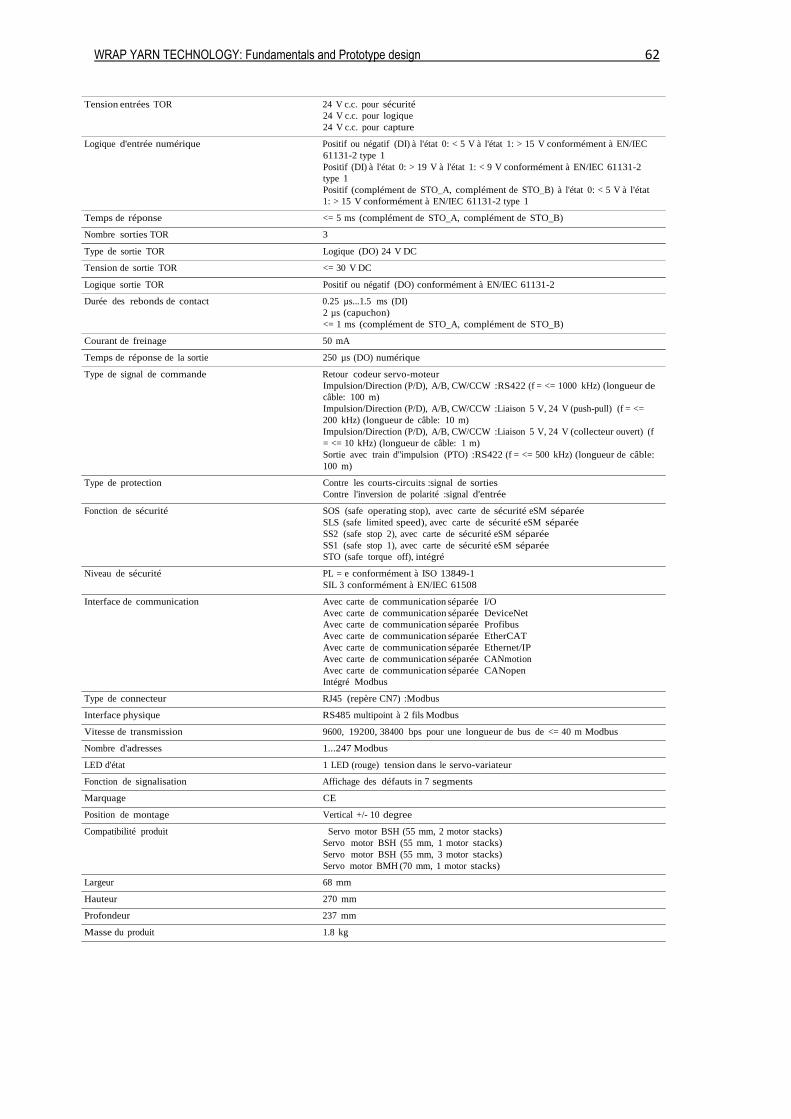
WRAP YARN TECHNOLOGY: Fundamentals and Prototype design 62
Tension entrées TOR 24 V c.c. pour sécurité
24 V c.c. pour logique
24 V c.c. pour capture
Logique d'entrée numérique Positif ou négatif (DI) à l'état 0: < 5 V à l'état 1: > 15 V conformément à EN/IEC
61131-2 type 1
Positif (DI) à l'état 0: > 19 V à l'état 1: < 9 V conformément à EN/IEC 61131-2
type 1
Positif (complément de STO_A, complément de STO_B) à l'état 0: < 5 V à l'état
1: > 15 V conformément à EN/IEC 61131-2 type 1
Temps de réponse <= 5 ms (complément de STO_A, complément de STO_B)
Nombre sorties TOR 3
Type de sortie TOR Logique (DO) 24 V DC
Tension de sortie TOR <= 30 V DC
Logique sortie TOR Positif ou négatif (DO) conformément à EN/IEC 61131-2
Durée des rebonds de contact 0.25 µs...1.5 ms (DI)
2 µs (capuchon)
<= 1 ms (complément de STO_A, complément de STO_B)
Courant de freinage 50 mA
Temps de réponse de la sortie 250 µs (DO) numérique
Type de signal de commande Retour codeur servo-moteur
Impulsion/Direction (P/D), A/B, CW/CCW :RS422 (f = <= 1000 kHz) (longueur de
câble: 100 m)
Impulsion/Direction (P/D), A/B, CW/CCW :Liaison 5 V, 24 V (push-pull) (f = <=
200 kHz) (longueur de câble: 10 m)
Impulsion/Direction (P/D), A/B, CW/CCW :Liaison 5 V, 24 V (collecteur ouvert) (f
= <= 10 kHz) (longueur de câble: 1 m)
Sortie avec train d''impulsion (PTO) :RS422 (f = <= 500 kHz) (longueur de câble:
100 m)
Type de protection Contre les courts-circuits :signal de sorties
Contre l'inversion de polarité :signal d'entrée
Fonction de sécurité SOS (safe operating stop), avec carte de sécurité eSM séparée
SLS (safe limited speed), avec carte de sécurité eSM séparée
SS2 (safe stop 2), avec carte de sécurité eSM séparée
SS1 (safe stop 1), avec carte de sécurité eSM séparée
STO (safe torque off), intégré
Niveau de sécurité PL = e conformément à ISO 13849-1
SIL 3 conformément à EN/IEC 61508
Interface de communication Avec carte de communication séparée I/O
Avec carte de communication séparée DeviceNet
Avec carte de communication séparée Profibus
Avec carte de communication séparée EtherCAT
Avec carte de communication séparée Ethernet/IP
Avec carte de communication séparée CANmotion
Avec carte de communication séparée CANopen
Intégré Modbus
Type de connecteur RJ45 (repère CN7) :Modbus
Interface physique RS485 multipoint à 2 fils Modbus
Vitesse de transmission 9600, 19200, 38400 bps pour une longueur de bus de <= 40 m Modbus
Nombre d'adresses 1...247 Modbus
LED d'état 1 LED (rouge) tension dans le servo-variateur
Fonction de signalisation Affichage des défauts in 7 segments
Marquage CE
Position de montage Vertical +/- 10 degree
Compatibilité produit Servo motor BSH (55 mm, 2 motor stacks)
Servo motor BSH (55 mm, 1 motor stacks)
Servo motor BSH (55 mm, 3 motor stacks)
Servo motor BMH (70 mm, 1 motor stacks)
Largeur 68 mm
Hauteur 270 mm
Profondeur 237 mm
Masse du produit 1.8 kg
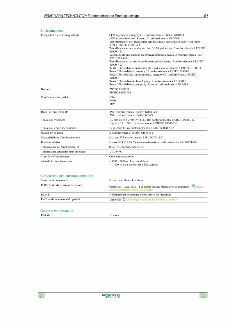
WRAP YARN TECHNOLOGY: Fundamentals and Prototype design 63
3 3
Environnement
Compatibilité électromagnétique CEM rayonnéeà category C3 conformément à EN/IEC 61800-3
CEM rayonnéeà class A group 2 conformément à EN 55011
Test d'immunité des transitoires rapides/salves électriquesà level 4 conformé-
ment à EN/IEC 61000-4-4
Test d'immunité aux ondes de choc 1,2/50 µsà niveau 3 conformément à EN/IEC
61000-4-5
Susceptibilité aux champs électromagnétiquesà niveau 3 conformément à EN/
IEC 61000-4-3
Test d'immunité de décharge électrostatiqueà niveau 3 conformément à EN/IEC
61000-4-2
Tests CEM réalisésà environments 1 and 2 conformément à EN/IEC 61800-3
Tests CEM réalisésà category C2 conformément à EN/IEC 61800-3
Tests CEM réalisésà environment 2 category C3 conformément à EN/IEC
61800-3
Tests CEM réalisésà class A group 2 conformément à EN 55011
Tests CEM réalisésà groupe 1, classe A conformément à EN 55011
Normes EN/IEC 61800-3
EN/IEC 61800-5-1
Certifications du produit CSA
RoHS
TÜV
UL
Degré de protection IP IP20 conformément à EN/IEC 61800-5-1
IP20 conformément à EN/IEC 60529
Tenue aux vibrations 1,5 mm crête-à-crête (f = 3...13 Hz) conformément à EN/IEC 60068-2-6
1 gn (f = 13...150 Hz) conformément à EN/IEC 60068-2-6
Tenue aux chocs mécaniques 15 gn pour 11 ms conformément à EN/IEC 60028-2-27
Niveau de pollution 2 conformément à EN/IEC 61800-5-1
Caractéristique d'environnement Classes 3C1 conformément à IEC 60721-3-3
Humidité relative Classe 3K3 (5 à 85 %) sans condensation conformément à IEC 60721-3-3
Température de fonctionnement 0...50 °C conformément à UL
Température ambiante pour stockage -25...70 °C
Type de refroidissement Convection naturelle
Altitude de fonctionnement > 1000...3000 m Avec conditions
<= 1000 m sans facteur de déclassement
Caractéristiques environnementales
Statut environnemental Produit non Green Premium
RoHS (code date: AnnéeSemaine) Compliant - since 0930 - Schneider Electric declaration of conformity Déclara-
tion de conformité Schneider Electric
REACh Reference not containing SVHC above the threshold
Profil environnemental du produit Disponible Télécharger Profil Environnemental Produit
Garantie contractuelle
Période 18 mois
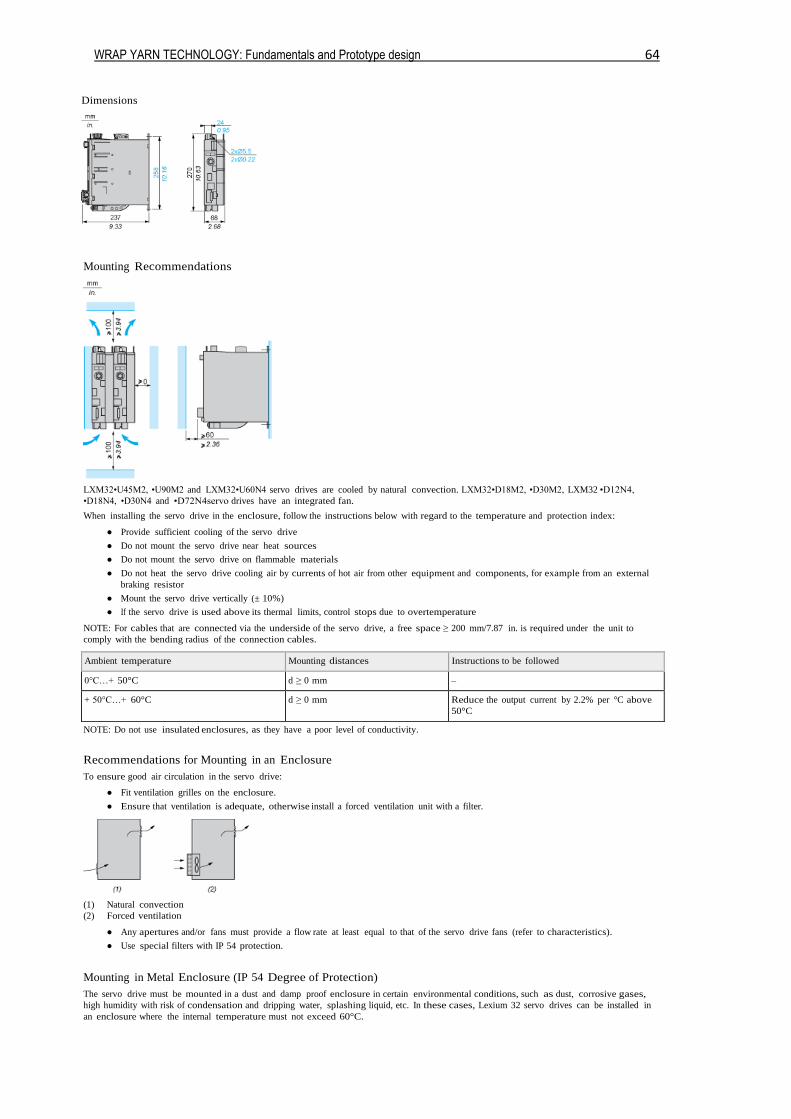
WRAP YARN TECHNOLOGY: Fundamentals and Prototype design 64
Dimensions
Mounting Recommendations
LXM32•U45M2, •U90M2 and LXM32•U60N4 servo drives are cooled by natural convection. LXM32•D18M2, •D30M2, LXM32 •D12N4,
•D18N4, •D30N4 and •D72N4servo drives have an integrated fan.
When installing the servo drive in the enclosure, follow the instructions below with regard to the temperature and protection index:
● Provide sufficient cooling of the servo drive
● Do not mount the servo drive near heat sources
● Do not mount the servo drive on flammable materials
● Do not heat the servo drive cooling air by currents of hot air from other equipment and components, for example from an external
braking resistor
● Mount the servo drive vertically (± 10%)
● If the servo drive is used above its thermal limits, control stops due to overtemperature
NOTE: For cables that are connected via the underside of the servo drive, a free space ≥ 200 mm/7.87 in. is required under the unit to
comply with the bending radius of the connection cables.
Ambient temperature Mounting distances Instructions to be followed
0°C…+ 50°C d ≥ 0 mm –
+ 50°C…+ 60°C d ≥ 0 mm Reduce the output current by 2.2% per °C above
50°C
NOTE: Do not use insulated enclosures, as they have a poor level of conductivity.
Recommendations for Mounting in an Enclosure
To ensure good air circulation in the servo drive:
● Fit ventilation grilles on the enclosure.
● Ensure that ventilation is adequate, otherwise install a forced ventilation unit with a filter.
(1) Natural convection
(2) Forced ventilation
● Any apertures and/or fans must provide a flow rate at least equal to that of the servo drive fans (refer to characteristics).
● Use special filters with IP 54 protection.
Mounting in Metal Enclosure (IP 54 Degree of Protection)
The servo drive must be mounted in a dust and damp proof enclosure in certain environmental conditions, such as dust, corrosive gases,
high humidity with risk of condensation and dripping water, splashing liquid, etc. In these cases, Lexium 32 servo drives can be installed in
an enclosure where the internal temperature must not exceed 60°C.
WRAP YARN TECHNOLOGY: Fundamentals and Prototype design 65
8. Bibliography
LAWRENCE, Carl A. Fundamentals of Spun Yarn Technologies. CRC Press LLC, 2003.
KLEIN, Werner. The Rieter Manual of Spinning. Volume 1 - Technology of Short-staple
Spinning. Rieter Machine Works Ltd, 2014.
KLEIN, Werner; Dr. STALDER, Herbert. The Rieter Manual of Spinning. Volume 4 – Ring
Spinning. Rieter Machine Works Ltd, 2014.
Dr. STALDER, Herbert. The Rieter Manual of Spinning. Volume 6 – Alternative Spinning
Systems. Rieter Machine Works Ltd 2014.
BRYDON, A.G; Van der MERWE, J.P. Wrap Spinning: Principles and Development.
SAWTRI Special Publication – February 1986. Republic of South Africa.
SHEPPARD, Laurel M. Made how - Volume 3 – Yarn. [Online]. [Consulted the 26th February 2015]. Available at:
http://www.madehow.com/Volume-3/Yarn.html
De La CRUZ ROMERO, Richard. Cardan Universal Joint. [Online video]. Published the 16th May 2010 [Consulted the 10th April 2015]. Available at:
https://www.youtube.com/watch?v=F8xEfygF3tY