Embed Size (px)
Citation preview
86
Greater efficiency, better performance, greater smoothness:
Our precision right angle series is a winner with its reduced running
noise, compact designed, and improved installation comfort.
The right angle gearbox
of PLN series
• Low backlash
• High output torque – the industry‘s
highest torque density
• Small installation space
• Precise, easy, and flexible motor mounting
(PCS-2 system)
• Balanced motor pinion
• High efficiency
• Ground and honed gearing
• 12 ratios 4:1 to 100:1
• Low noise
• Consistent quality (ISO 9001 and 14001)
• Operable in any mounting position
• Lifetime lubrication
• Numerous options
• Balanced motor connection
WPLNPrecision Line
87
1 Technical data page 88
2 Dimensions page 91
3 Product code page 98
4 Output flange design – WPLS-compatible page 104
5 Input design – universal flange page 106
6 Technical background page 109
7 Dimensioning / Calculation page 4 – www.neugart.com and Neugart Calculation Program (NCP)
8 CAD drawings, Dimension sheets page 5 – www.neugart.com and Tec Data Finder (TDF)
88
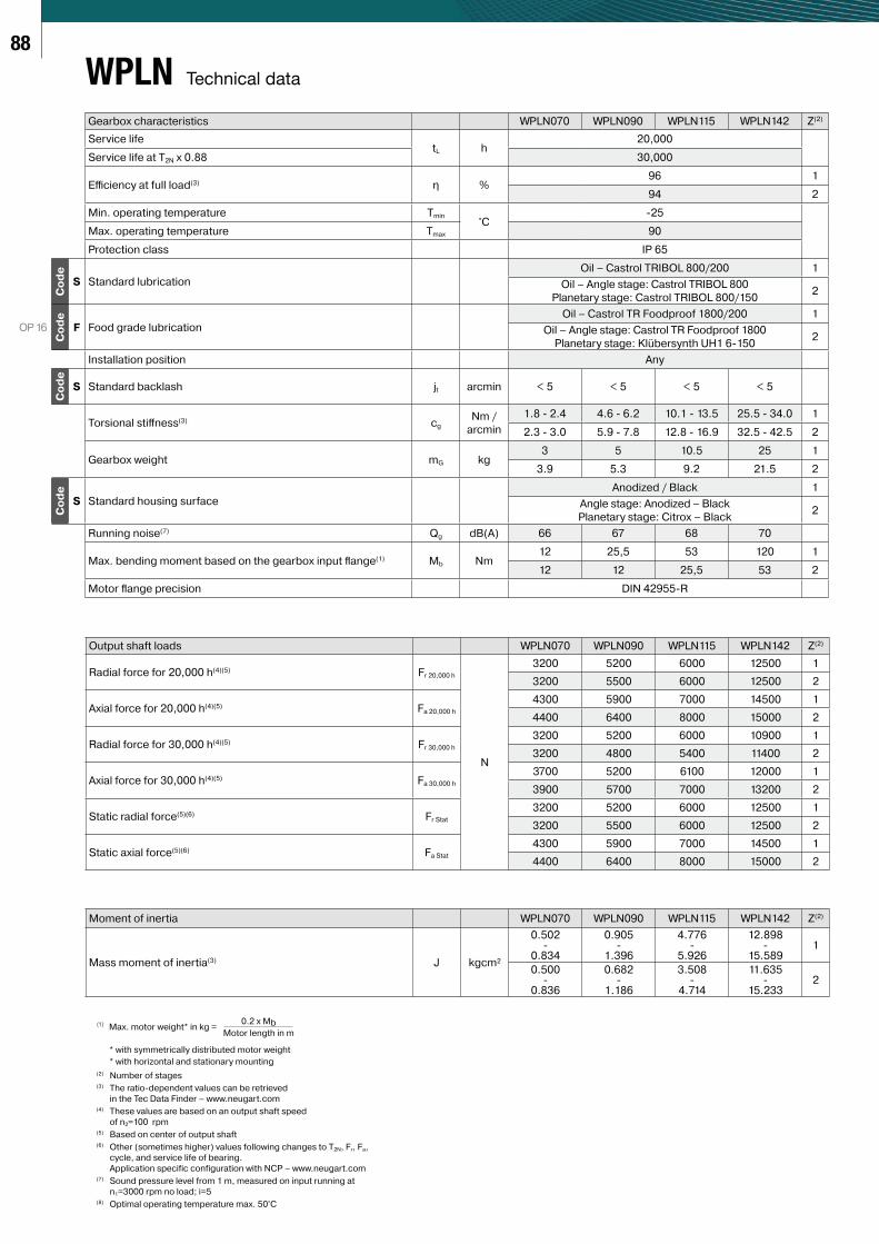
Gearbox characteristics WPLN070 WPLN090 WPLN115 WPLN142 Z(2)
Service lifetL h
20,000
Service life at T2N x 0.88 30,000
Effi ciency at full load(3) η %96 1
94 2
Min. operating temperature Tmin°C
-25
Max. operating temperature Tmax 90
Protection class IP 65
Co
de
S Standard lubrication
Oil – Castrol TRIBOL 800/200 1
Oil – Angle stage: Castrol TRIBOL 800
Planetary stage: Castrol TRIBOL 800/150 2
OP 16
Co
de
F Food grade lubrication
Oil – Castrol TR Foodproof 1800/200 1
Oil – Angle stage: Castrol TR Foodproof 1800
Planetary stage: Klübersynth UH1 6-1502
Installation position Any
Co
de
S Standard backlash jt arcmin < 5 < 5 < 5 < 5
Torsional stiff ness(3) cg
Nm /
arcmin
1.8 - 2.4 4.6 - 6.2 10.1 - 13.5 25.5 - 34.0 1
2.3 - 3.0 5.9 - 7.8 12.8 - 16.9 32.5 - 42.5 2
Gearbox weight mG kg3 5 10.5 25 1
3.9 5.3 9.2 21.5 2
Co
de
S Standard housing surface
Anodized / Black 1
Angle stage: Anodized – Black
Planetary stage: Citrox – Black2
Running noise(7) Qg dB(A) 66 67 68 70
Max. bending moment based on the gearbox input fl ange(1) Mb Nm12 25,5 53 120 1
12 12 25,5 53 2
Motor fl ange precision DIN 42955-R
Output shaft loads WPLN070 WPLN090 WPLN115 WPLN142 Z(2)
Radial force for 20,000 h(4)(5) Fr 20,000 h
N
3200 5200 6000 12500 1
3200 5500 6000 12500 2
Axial force for 20,000 h(4)(5) Fa 20,000 h
4300 5900 7000 14500 1
4400 6400 8000 15000 2
Radial force for 30,000 h(4)(5) Fr 30,000 h
3200 5200 6000 10900 1
3200 4800 5400 11400 2
Axial force for 30,000 h(4)(5) Fa 30,000 h
3700 5200 6100 12000 1
3900 5700 7000 13200 2
Static radial force(5)(6) Fr Stat
3200 5200 6000 12500 1
3200 5500 6000 12500 2
Static axial force(5)(6) Fa Stat
4300 5900 7000 14500 1
4400 6400 8000 15000 2
Moment of inertia WPLN070 WPLN090 WPLN115 WPLN142 Z(2)
Mass moment of inertia(3) J kgcm²
0.502-
0.834
0.905-
1.396
4.776-
5.926
12.898-
15.5891
0.500-
0.836
0.682-
1.186
3.508-
4.714
11.635-
15.2332
Technical dataWPLN
(2) Number of stages(3) The ratio-dependent values can be retrieved
in the Tec Data Finder – www.neugart.com(4) These values are based on an output shaft speed
of n2=100 rpm(5) Based on center of output shaft(6) Other (sometimes higher) values following changes to T2N, Fr, Fa,
cycle, and service life of bearing.
Application specific configuration with NCP – www.neugart.com(7) Sound pressure level from 1 m, measured on input running at
n1=3000 rpm no load; i=5(8) Optimal operating temperature max. 50°C
(1) Max. motor weight* in kg = 0.2 x Mb
Motor length in m
* with symmetrically distributed motor weight
* with horizontal and stationary mounting
89
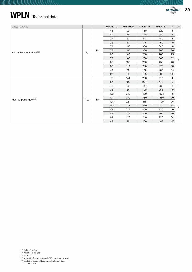
Technical dataWPLNOutput torques WPLN070 WPLN090 WPLN115 WPLN142 i(1) Z(2)
Nominal output torque(3)(4) T2NNm
45 90 160 320 4
142 75 140 280 5
27 50 90 180 8
22 40 75 160 10
77 150 300 640 16
2
77 150 300 800 20
65 140 260 700 25
77 108 200 360 32
65 135 250 450 40
65 110 200 375 50
40 80 150 450 64
27 60 125 305 100
Max. output torque(4)(5) T2max Nm
72 144 256 512 4
167 120 224 448 5
43 80 144 288 8
35 64 120 256 10
123 240 480 1024 16
2
123 240 480 1280 20
104 224 416 1120 25
123 172 320 576 32
104 216 400 720 40
104 176 320 600 50
64 128 240 720 64
43 96 200 488 100
(1) Ratios (i=n1/n2)(2) Number of stages(3) For n1N(4) Values for feather key (code “A”): for repeated load(5) 30,000 rotations of the output shaft permitted;
see page 109
90
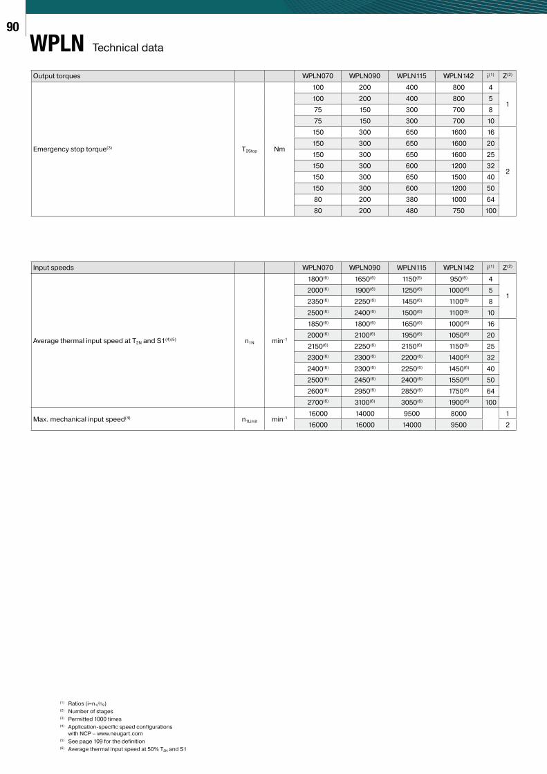
Output torques WPLN070 WPLN090 WPLN115 WPLN142 i(1) Z(2)
Emergency stop torque(3) T2Stop Nm
100 200 400 800 4
1100 200 400 800 5
75 150 300 700 8
75 150 300 700 10
150 300 650 1600 16
2
150 300 650 1600 20
150 300 650 1600 25
150 300 600 1200 32
150 300 650 1500 40
150 300 600 1200 50
80 200 380 1000 64
80 200 480 750 100
Input speeds WPLN070 WPLN090 WPLN115 WPLN142 i(1) Z(2)
Average thermal input speed at T2N and S1(4)(5) n1N min-1
1800(6) 1650(6) 1150(6) 950(6) 4
12000(6) 1900(6) 1250(6) 1000(6) 5
2350(6) 2250(6) 1450(6) 1100(6) 8
2500(6) 2400(6) 1500(6) 1100(6) 10
1850(6) 1800(6) 1650(6) 1000(6) 16
2000(6) 2100(6) 1950(6) 1050(6) 20
2150(6) 2250(6) 2150(6) 1150(6) 25
2300(6) 2300(6) 2200(6) 1400(6) 32
2400(6) 2300(6) 2250(6) 1450(6) 40
2500(6) 2450(6) 2400(6) 1550(6) 50
2600(6) 2950(6) 2850(6) 1750(6) 64
2700(6) 3100(6) 3050(6) 1900(6) 100
Max. mechanical input speed(4) n1Limit min-116000 14000 9500 8000 1
16000 16000 14000 9500 2
Technical dataWPLN
(1) Ratios (i=n1/n2)(2) Number of stages(3) Permitted 1000 times(4) Application-specific speed configurations
with NCP – www.neugart.com(5) See page 109 for the definition(6) Average thermal input speed at 50% T2N and S1
91
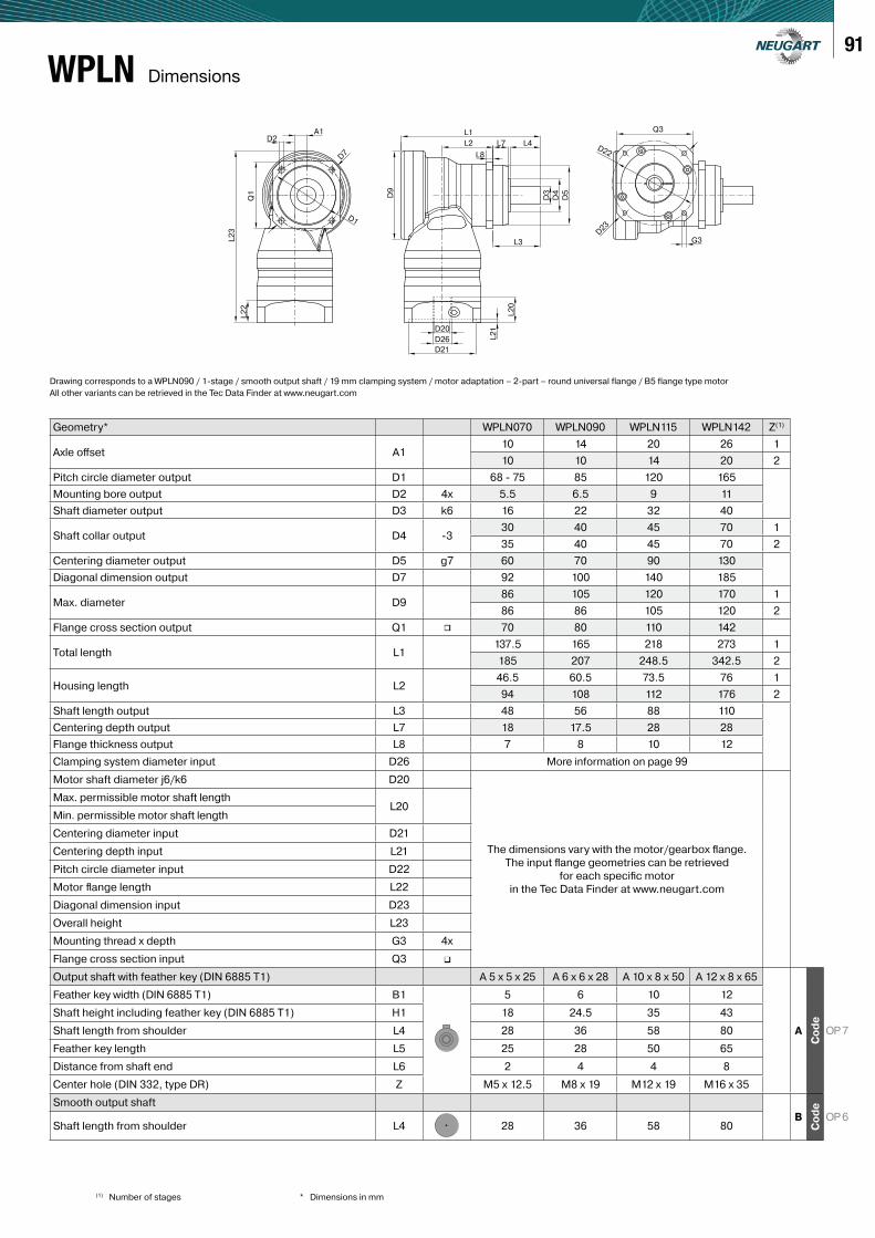
Geometry* WPLN070 WPLN090 WPLN115 WPLN142 Z(1)
Axle off set A110 14 20 26 1
10 10 14 20 2
Pitch circle diameter output D1 68 - 75 85 120 165
Mounting bore output D2 4x 5.5 6.5 9 11
Shaft diameter output D3 k6 16 22 32 40
Shaft collar output D4 -330 40 45 70 1
35 40 45 70 2
Centering diameter output D5 g7 60 70 90 130
Diagonal dimension output D7 92 100 140 185
Max. diameter D986 105 120 170 1
86 86 105 120 2
Flange cross section output Q1 ∎ 70 80 110 142
Total length L1137.5 165 218 273 1
185 207 248.5 342.5 2
Housing length L246.5 60.5 73.5 76 1
94 108 112 176 2
Shaft length output L3 48 56 88 110
Centering depth output L7 18 17.5 28 28
Flange thickness output L8 7 8 10 12
Clamping system diameter input D26 More information on page 99
Motor shaft diameter j6/k6 D20
The dimensions vary with the motor/gearbox fl ange.
The input fl ange geometries can be retrieved
for each specifi c motor
in the Tec Data Finder at www.neugart.com
Max. permissible motor shaft lengthL20
Min. permissible motor shaft length
Centering diameter input D21
Centering depth input L21
Pitch circle diameter input D22
Motor fl ange length L22
Diagonal dimension input D23
Overall height L23
Mounting thread x depth G3 4x
Flange cross section input Q3 ∎
Output shaft with feather key (DIN 6885 T1) A 5 x 5 x 25 A 6 x 6 x 28 A 10 x 8 x 50 A 12 x 8 x 65
A
Co
de
OP 7
Feather key width (DIN 6885 T1) B1 5 6 10 12
Shaft height including feather key (DIN 6885 T1) H1 18 24.5 35 43
Shaft length from shoulder L4 28 36 58 80
Feather key length L5 25 28 50 65
Distance from shaft end L6 2 4 4 8
Center hole (DIN 332, type DR) Z M5 x 12.5 M8 x 19 M12 x 19 M16 x 35
Smooth output shaft
B
Co
de
OP 6Shaft length from shoulder L4 28 36 58 80
A1 L1
G3
Q3
D22
D23
L2
L3
D20
D26
D21
L8
L7 L4
D7
D2
D1
D9
L2
1
L2
0
D5
D4
D3
L2
3
L2
2Q
1
DimensionsWPLN
Drawing corresponds to a WPLN090 / 1-stage / smooth output shaft / 19 mm clamping system / motor adaptation – 2-part – round universal flange / B5 flange type motor
All other variants can be retrieved in the Tec Data Finder at www.neugart.com
(1) Number of stages * Dimensions in mm
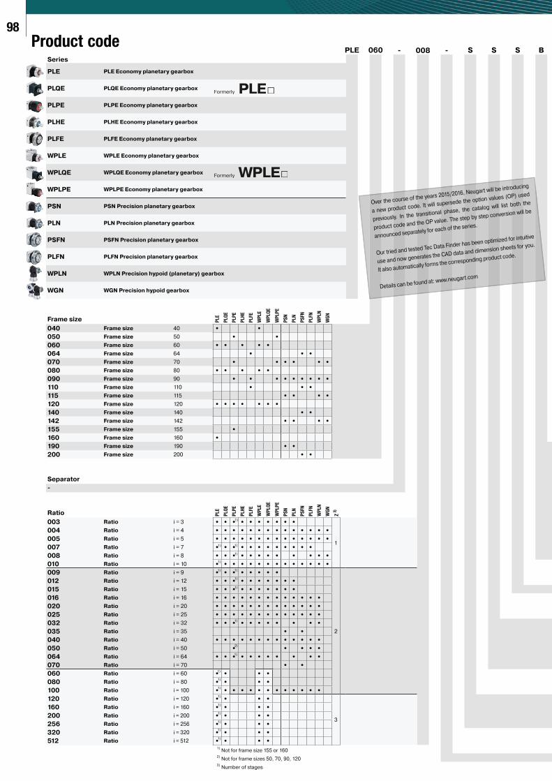
98
Product codeSeries
PLE 060 - 008 - S S S B
PLE PLE Economy planetary gearbox
PLQE PLQE Economy planetary gearbox
PLPE PLPE Economy planetary gearbox
PLHE PLHE Economy planetary gearbox
PLFE PLFE Economy planetary gearbox
WPLE WPLE Economy planetary gearbox
WPLQE WPLQE Economy planetary gearbox
WPLPE WPLPE Economy planetary gearbox
PSN PSN Precision planetary gearbox
PLN PLN Precision planetary gearbox
PSFN PSFN Precision planetary gearbox
PLFN PLFN Precision planetary gearbox
WPLN WPLN Precision hypoid (planetary) gearbox
WGN WGN Precision hypoid gearbox
Frame size PLE
PLQ
E
PLP
E
PLH
E
PLFE
WP
LE
WP
LQ
E
WP
LP
E
PS
N
PLN
PS
FN
PLFN
WP
LN
WG
N040 Frame size 40 • •
050 Frame size 50 • •
060 Frame size 60 • • • • •
064 Frame size 64 • • •
070 Frame size 70 • • • • • •
080 Frame size 80 • • • • •
090 Frame size 90 • • • • • • • • •
110 Frame size 110 • • •
115 Frame size 115 • • • •
120 Frame size 120 • • • • • • •
140 Frame size 140 • •
142 Frame size 142 • • • •
155 Frame size 155 •
160 Frame size 160 •
190 Frame size 190 • •
200 Frame size 200 • •
Separator
-
Ratio PLE
PLQ
E
PLP
E
PLH
E
PLFE
WP
LE
WP
LQ
E
WP
LP
E
PS
N
PLN
PS
FN
PLFN
WP
LN
WG
N
Z 3
)
003 Ratio i = 3 • • • • • • • • • •
1
004 Ratio i = 4 • • • • • • • • • • • • • •
005 Ratio i = 5 • • • • • • • • • • • • • •
007 Ratio i = 7 • • • • • • • • • • • •
008 Ratio i = 8 • • • • • • • • • • • •
010 Ratio i = 10 • • • • • • • • • • • • • •
009 Ratio i = 9 • • • • • • • •
2
012 Ratio i = 12 • • • • • • • • • •
015 Ratio i = 15 • • • • • • • • • •
016 Ratio i = 16 • • • • • • • • • • • • •
020 Ratio i = 20 • • • • • • • • • • • • •
025 Ratio i = 25 • • • • • • • • • • • • •
032 Ratio i = 32 • • • • • • • • • • •
035 Ratio i = 35 • •
040 Ratio i = 40 • • • • • • • • • • • • •
050 Ratio i = 50 • • • • •
064 Ratio i = 64 • • • • • • • • • • •
070 Ratio i = 70 • •
060 Ratio i = 60 • • • •
080 Ratio i = 80 • • • •
100 Ratio i = 100 • • • • • • • • • • • • •
120 Ratio i = 120 • • • •
3
160 Ratio i = 160 • • • •
200 Ratio i = 200 • • • •
256 Ratio i = 256 • • • •
320 Ratio i = 320 • • • •
512 Ratio i = 512 • • • •
1)Not for frame size 155 or 160
2)Not for frame sizes 50, 70, 90, 120
3)Number of stages
1)
1)1)
1)
1)
1)1)
1)
1)
2)
1)
1)
1)
1)
1)
1)
1)
1)
1)
1)
1)
Formerly PLE
Formerly WPLE
Over the course of the years 2015/2016, Neugart will be introducing
a new product code. It will supersede the option values (OP) used
previously. In the transitional phase, the catalog will list both the
product code and the OP value. The step by step conversion will be
announced separately for each of the series.
Our tried and tested Tec Data Finder has been optimized for intuitive
use and now generates the CAD data and dimension sheets for you.
It also automatically forms the corresponding product code.
Details can be found at: www.neugart.com
99
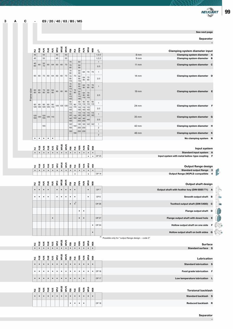
3 A C - E9 / 20 / 40 / 63 / B5 / M5
See next page
Separator
-
PLE
PLQ
E
PLP
E
PLH
E
PLFE
WP
LE
WP
LQ
E
WP
LP
E
PS
N
PLN
PS
FN
PLFN
WP
LN
WG
N
Input system
• • • • • • • • • • • • • • Standard input system A
• • OP 25 Input system with metal bellow-type coupling F
PLE
PLQ
E
PLP
E
PLH
E
PLFE
WP
LE
WP
LQ
E
WP
LP
E
PS
N
PLN
PS
FN
PLFN
WP
LN
WG
N
Output fl ange design
• • • • • • • • • • • • • • Standard output fl ange 3
• • OP 14 Output fl ange (W)PLS-compatible 4
PLE
PLQ
E
PLP
E
PLH
E
PLFE
WP
LE
WP
LQ
E
WP
LP
E
PS
N
PLN
PS
FN
PLFN
WP
LN
WG
N
Z 3
)
Clamping system diameter input
40 50 40 50 1/2/3 8 mm Clamping system diameter A
40 50 40 50 1/2/3 9 mm Clamping system diameter B
40
6060
50
7060 64 60 60 70
70 64 1
11 mm Clamping system diameter C70
90
64
902/3
60 60 70 60 64 60 60 70
70
90
70
64
9064 70 70 1
14 mm Clamping system diameter D70
90
115
64
90
110
64
90
70
902/3
60
80
60
80
70
90
60
80
64
9080 80 90
70
90
11570
90
64
90
110
64
90
70
90
70
901
19 mm Clamping system diameter E70
90
115
142
64
90
110
140
64
90
110
70
90
115
2/3
80
120
80
120
90
120
80
120
90
110120 120 120
90
115 90
115
90
110
90
110
90
115
90
1151
24 mm Clamping system diameter F115
142
110
140
110
140
115
1422/3
120
160120
120
155120 110
115
142 115
142
110
140
110
140
115
142
115
1421
35 mm Clamping system diameter G142
190
140
200
140
200142 2/3
155142
142140 140 142 142 1
42 mm Clamping system diameter H190 200 200 2
190190
200 200 148 mm Clamping system diameter K
2
• • • • • No clamping system N
PLE
PLQ
E
PLP
E
PLH
E
PLFE
WP
LE
WP
LQ
E
WP
LP
E
PS
N
PLN
PS
FN
PLFN
WP
LN
WG
N
Surface
• • • • • • • • • • • • • • Standard surface S
PLE
PLQ
E
PLP
E
PLH
E
PLFE
WP
LE
WP
LQ
E
WP
LP
E
PS
N
PLN
PS
FN
PLFN
WP
LN
WG
N
Lubrication
• • • • • • • • • • • • • • Standard lubrication S
• • • • • • • • • • • • • • OP 16 Food grade lubrication F
• • • • • • • • • • • • OP 17 Low temperature lubrication L
PLE
PLQ
E
PLP
E
PLH
E
PLFE
WP
LE
WP
LQ
E
WP
LP
E
PS
N
PLN
PS
FN
PLFN
WP
LN
WG
N
Torsional backlash
• • • • • • • • • • • • • • Standard backlash S
• • • • OP 18 Reduced backlash R
Separator
-
PLE
PLQ
E
PLP
E
PLH
E
PLFE
WP
LE
WP
LQ
E
WP
LP
E
PS
N
PLN
PS
FN
PLFN
WP
LN
WG
N
Output shaft design
• • • • • • • • • • OP 7 Output shaft with feather key (DIN 6885 T1) A
• • • • • • • • • • OP 6 Smooth output shaft B
• • OP 26 Toothed output shaft (DIN 5480) C
• • Flange output shaft D
• • • OP 27 Flange output shaft with dowel hole E
• OP 24 Hollow output shaft on one side F
• Hollow output shaft on both sides G
A)Possible only for “output fl ange design – code 3”
A)
Fra
me
siz
e
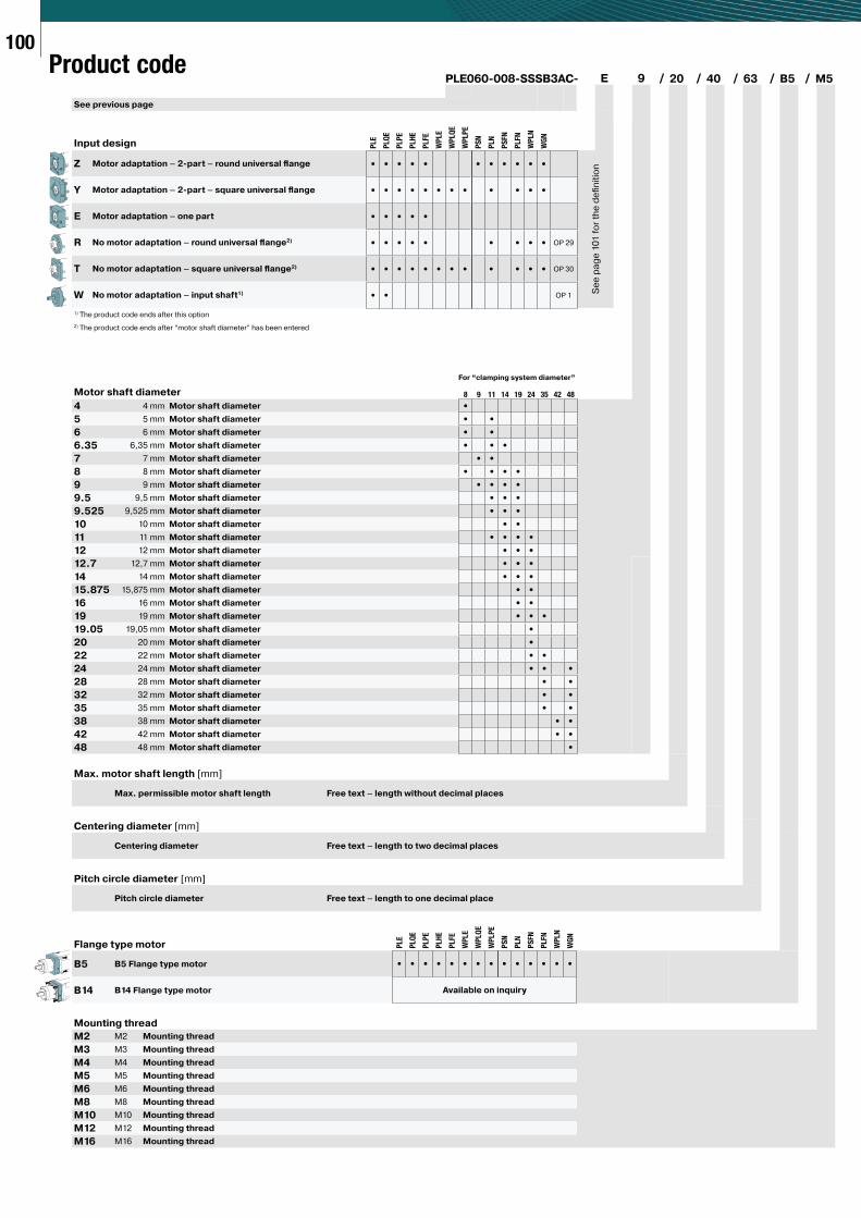
100
PLE060-008-SSSB3AC- E 9 / 20 / 40 / 63 / B5 / M5
See previous page
Input design
Z Motor adaptation – 2-part – round universal fl ange
Y Motor adaptation – 2-part – square universal fl ange
E Motor adaptation – one part
R No motor adaptation – round universal fl ange2)
T No motor adaptation – square universal fl ange2)
W No motor adaptation – input shaft1)
1) The product code ends after this option
2) The product code ends after “motor shaft diameter” has been entered
For “clamping system diameter”
Motor shaft diameter
4 4 mm Motor shaft diameter
5 5 mm Motor shaft diameter
6 6 mm Motor shaft diameter
6.35 6,35 mm Motor shaft diameter
7 7 mm Motor shaft diameter
8 8 mm Motor shaft diameter
9 9 mm Motor shaft diameter
9.5 9,5 mm Motor shaft diameter
9.525 9,525 mm Motor shaft diameter
10 10 mm Motor shaft diameter
11 11 mm Motor shaft diameter
12 12 mm Motor shaft diameter
12.7 12,7 mm Motor shaft diameter
14 14 mm Motor shaft diameter
15.875 15,875 mm Motor shaft diameter
16 16 mm Motor shaft diameter
19 19 mm Motor shaft diameter
19.05 19,05 mm Motor shaft diameter
20 20 mm Motor shaft diameter
22 22 mm Motor shaft diameter
24 24 mm Motor shaft diameter
28 28 mm Motor shaft diameter
32 32 mm Motor shaft diameter
35 35 mm Motor shaft diameter
38 38 mm Motor shaft diameter
42 42 mm Motor shaft diameter
48 48 mm Motor shaft diameter
Max. motor shaft length [mm]
Max. permissible motor shaft length Free text – length without decimal places
Centering diameter [mm]
Centering diameter Free text – length to two decimal places
Pitch circle diameter [mm]
Pitch circle diameter Free text – length to one decimal place
Flange type motor
B5 B5 Flange type motor
B14 B14 Flange type motor
Mounting thread
M2 M2 Mounting thread
M3 M3 Mounting thread
M4 M4 Mounting thread
M5 M5 Mounting thread
M6 M6 Mounting thread
M8 M8 Mounting thread
M10 M10 Mounting thread
M12 M12 Mounting thread
M16 M16 Mounting thread
Product code
8 9 11 14 19 24 35 42 48
•
• •
• •
• • •
• •
• • • •
• • • •
• • •
• • •
• •
• • • •
• • •
• • •
• • •
• •
• •
• • •
•
•
• •
• • •
• •
• •
• •
• •
• •
•
Se
e p
ag
e 1
01
fo
r th
e d
efi
nit
ion
PLE
PLQ
E
PLP
E
PLH
E
PLFE
WP
LE
WP
LQ
E
WP
LP
E
PS
N
PLN
PS
FN
PLFN
WP
LN
WG
N
• • • • • • • • • • •
• • • • • • • • • • • •
• • • • •
• • • • • • • • • OP 29
• • • • • • • • • • • • OP 30
• • OP 1
PLE
PLQ
E
PLP
E
PLH
E
PLFE
WP
LE
WP
LQ
E
WP
LP
E
PS
N
PLN
PS
FN
PLFN
WP
LN
WG
N
• • • • • • • • • • • • • •
Available on inquiry
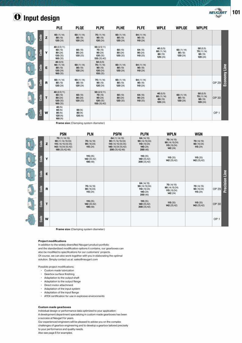
101Input design
Frame size (Clamping system diameter)
Frame size (Clamping system diameter)
Project modifi cations
In addition to the widely diversifi ed Neugart product portfolio
and the standardized modifi cation options it contains, our gearboxes can
also be modifi ed to specifi cations for our customers’ projects.
Of course, we can also work together with you in elaborating the optimal
solution. Simply contact us at: [email protected]
Possible project modifi cations:
• Custom made lubrication
• Gearbox surface fi nishing
• Adaptation to the output shaft
• Adaptation to the output fl ange
• Direct motor attachment
• Adaptation of the input system
• Adaptation of the input fl ange
• ATEX certifi cation for use in explosive environments
Custom made gearboxes
Individual design or performance data optimized to your application:
A development department specializing in custom made gearboxes has been
a success at Neugart for years.
Our experienced engineers will be pleased to advise you on the complex
challenges of gearbox engineering and to develop a gearbox tailored precisely
to your performance and quality needs.
Also see page 8 for examples.
PLE PLQE PLPE PLHE PLFE WPLE WPLQE WPLPE
Co
de
Z60 (11/14)
80 (19)
120 (24)
60 (11/14)
80 (19)
120 (24)
70 (11/14)
90 (19)
120 (24)
60 (11/14)
80 (19)
120 (24)
64 (11/14)
90 (19)
110 (24)
Econ
om
y Lin
e
Co
de
Y
40 (8/9/11)
60 (19)
80 (24)
120 (35)
160 (35)
60 (19)
80 (24)
120 (35)
50 (8/9/11)
70 (19)
90 (24)
120 (35)
155 (35/42)
60 (19)
80 (24)
120 (35)
64 (19)
90 (24)
110 (35)
40 (8/9)
60 (11/14)
80 (19)
120 (24)
60 (11/14)
80 (19)
120 (24)
50 (8/9)
70 (11/14)
90 (19)
120 (24)
Co
de
E
40 (8/9)
60 (11/14)
80 (19)
120 (24)
160 (35)
60 (11/14)
80 (19)
120 (24)
50 (8/9)
70 (11/14)
90 (19)
120 (24)
155 (35)
60 (11/14)
80 (19)
120 (24)
64 (11/14)
90 (19)
110 (24)
Co
de
R60 (11/14)
80 (19)
120 (24)
60 (11/14)
80 (19)
120 (24)
70 (11/14)
90 (19)
120 (24)
60 (11/14)
80 (19)
120 (24)
64 (11/14)
90 (19)
110 (24)OP 29
Co
de
T
40 (8/9/11)
60 (19)
80 (24)
120 (35)
160 (35)
60 (19)
80 (24)
120 (35)
50 (8/9/11)
70 (19)
90 (24)
120 (35)
155 (35/42)
60 (19)
80 (24)
120 (35)
64 (19)
90 (24)
110 (35)
40 (8/9)
60 (11/14)
80 (19)
120 (24)
60 (11/14)
80 (19)
120 (24)
50 (8/9)
70 (11/14)
90 (19)
120 (24)
OP 30
Co
de
W
40 (N)
60 (N)
80 (N)
120 (N)
160 (N)
60 (N)
80 (N)
120 (N)OP 1
PSN PLN PSFN PLFN WPLN WGN
Cod
e
Z
70 (11/14/19)
90 (11/14/19/24)
115 (14/19/24/35)
142 (19/24/35/42)
190 (35/42/48)
70 (14/19)
90 (19/24)
115 (24)
64 (11/14/19)
90 (11/14/19/24)
110 (14/19/24/35)
140 (19/24/35/42)
200 (35/42/48)
64 (14/19)
90 (14/19/24)
110 (19/24)
140 (24)
200 (48)
70 (14/19)
90 (14/19/24)
115 (19/24)
142 (24)
70 (14/19)
90 (19/24)
115 (24)
Pre
cis
ion
Lin
e
Cod
e
Y115 (35)
142 (35/42)
190 (48)
110 (35)
140 (35/42)
200 (35/42)
115 (35)
142 (35/42)
115 (35)
142 (35/42)
Cod
e
E
Cod
e
R70 (14/19)
90 (19/24)
115 (24)
64 (14/19)
90 (14/19/24)
110 (19/24)
140 (24)
200 (48)
70 (14/19)
90 (14/19/24)
115 (19/24)
142 (24)
70 (14/19)
90 (19/24)
115 (24)OP 29
Cod
e
T115 (35)
142 (35/42)
190 (48)
110 (35)
140 (35/42)
200 (35/42)
115 (35)
142 (35/42)
115 (35)
142 (35/42)OP 30
Cod
e
W OP 1
104C
od
e
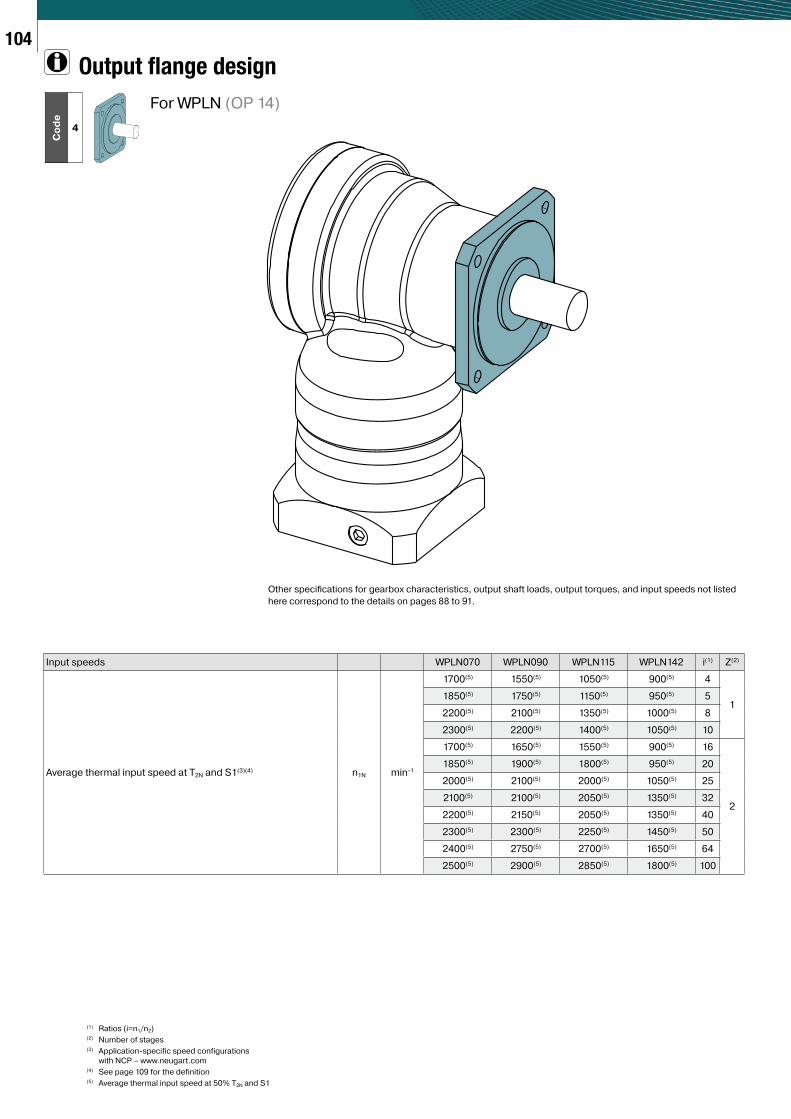
4
Output flange design
(1) Ratios (i=n1/n2)(2) Number of stages(3) Application-specific speed configurations
with NCP – www.neugart.com(4) See page 109 for the definition(5) Average thermal input speed at 50% T2N and S1
Input speeds WPLN070 WPLN090 WPLN115 WPLN142 i(1) Z(2)
Average thermal input speed at T2N and S1(3)(4) n1N min-1
1700(5) 1550(5) 1050(5) 900(5) 4
11850(5) 1750(5) 1150(5) 950(5) 5
2200(5) 2100(5) 1350(5) 1000(5) 8
2300(5) 2200(5) 1400(5) 1050(5) 10
1700(5) 1650(5) 1550(5) 900(5) 16
2
1850(5) 1900(5) 1800(5) 950(5) 20
2000(5) 2100(5) 2000(5) 1050(5) 25
2100(5) 2100(5) 2050(5) 1350(5) 32
2200(5) 2150(5) 2050(5) 1350(5) 40
2300(5) 2300(5) 2250(5) 1450(5) 50
2400(5) 2750(5) 2700(5) 1650(5) 64
2500(5) 2900(5) 2850(5) 1800(5) 100
For WPLN (OP 14)
Other specifi cations for gearbox characteristics, output shaft loads, output torques, and input speeds not listed
here correspond to the details on pages 88 to 91.
105
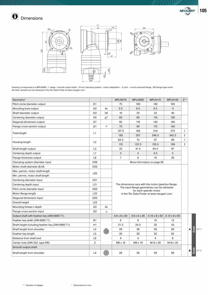
(1) Number of stages * Dimensions in mm
G3
L1
L4
L7L2
D23
D22
Q3
L8
L3
L2
0
L2
1
D3
D5
D20
D26
D21
D2D
7
L2
3
Q1
L2
2
D1
Geometry* WPLN070 WPLN090 WPLN115 WPLN142 Z(1)
Pitch circle diameter output D1 75 100 130 165
Mounting bore output D2 4x 5.5 6.5 8.5 11
Shaft diameter output D3 k6 19 22 32 40
Centering diameter output D5 g7 60 80 110 130
Diagonal dimension output D7 92 116 145 185
Flange cross section output Q1 ∎ 70 90 115 142
Total length L1137.5 165 218 273 1
185 207 248.5 342.5 2
Housing length L262.5 75 97 99 1
110 122.5 135.5 199 2
Shaft length output L3 32 41.5 64.5 87
Centering depth output L7 3 3 4.5 5
Flange thickness output L8 7 8 10 20
Clamping system diameter input D26 More information on page 99
Motor shaft diameter j6/k6 D20
The dimensions vary with the motor/gearbox fl ange.
The input fl ange geometries can be retrieved
for each specifi c motor
in the Tec Data Finder at www.neugart.com
Max. permis. motor shaft lengthL20
Min. permis. motor shaft length
Centering diameter input D21
Centering depth input L21
Pitch circle diameter input D22
Motor fl ange length L22
Diagonal dimension input D23
Overall height L23
Mounting thread x depth G3 4x
Flange cross section input Q3 ∎
Output shaft with feather key (DIN 6885 T1) A 6 x 6 x 20 A 6 x 6 x 28 A 10 x 8 x 50 A 12 x 8 x 65
A
Co
de
OP 7
Feather key width (DIN 6885 T1) B1 6 6 10 12
Shaft height including feather key (DIN 6885 T1) H1 21.5 24.5 35 43
Shaft length from shoulder L4 28 36 58 80
Feather key length L5 20 28 50 65
Distance from shaft end L6 4 4 4 8
Center hole (DIN 332, type DR) Z M6 x 16 M8 x 19 M12 x 28 M16 x 35
Smooth output shaft
B
Co
de
OP 6Shaft length from shoulder L4 28 36 58 80
Dimensions
Drawing corresponds to a WPLN090 / 1-stage / smooth output shaft / 14 mm clamping system / motor adaptation – 2-part – round universal flange / B5 flange type motor
All other variants can be retrieved in the Tec Data Finder at www.neugart.com
106C
od
e
R
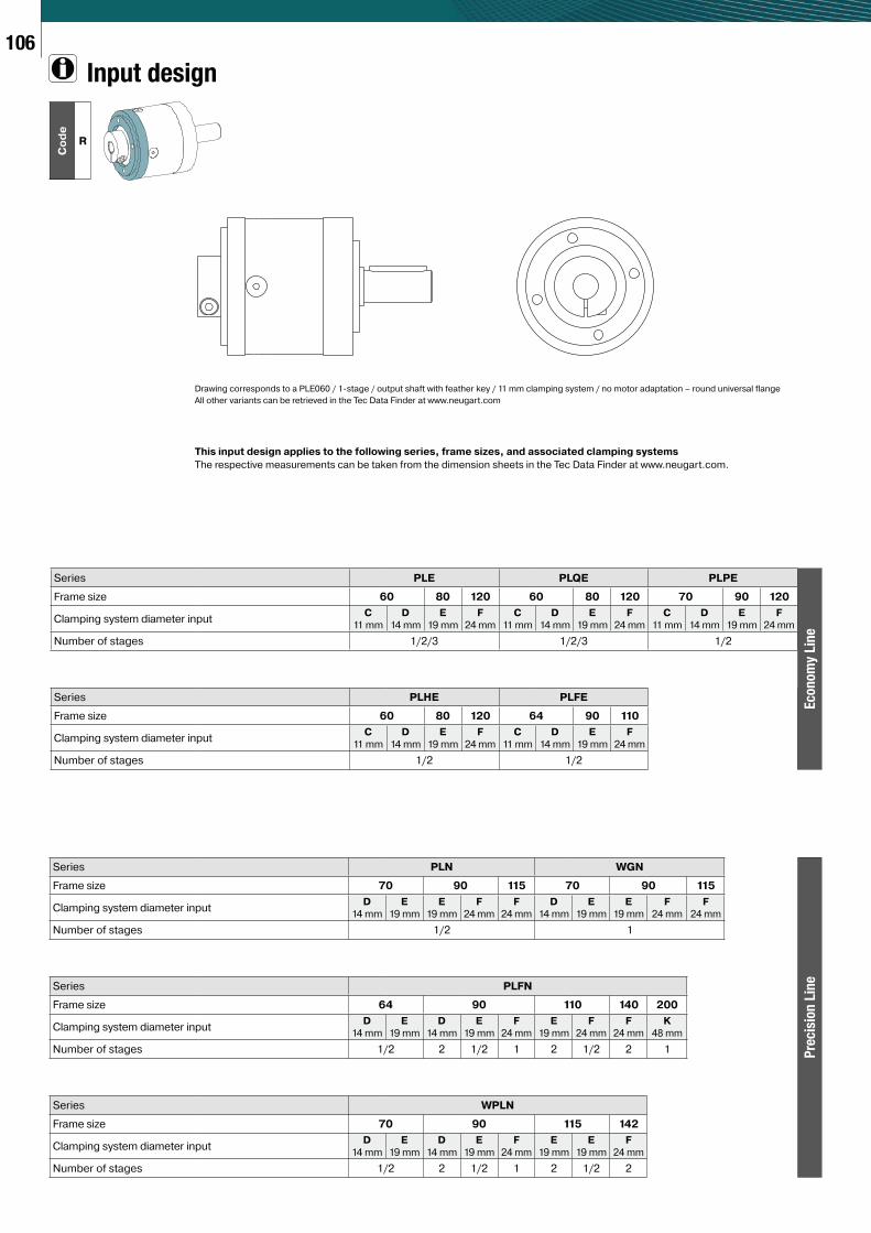
Input design
Drawing corresponds to a PLE060 / 1-stage / output shaft with feather key / 11 mm clamping system / no motor adaptation – round universal flange
All other variants can be retrieved in the Tec Data Finder at www.neugart.com
This input design applies to the following series, frame sizes, and associated clamping systems
The respective measurements can be taken from the dimension sheets in the Tec Data Finder at www.neugart.com.
Series PLE PLQE PLPE
Frame size 60 80 120 60 80 120 70 90 120
Clamping system diameter inputC
11 mm
D
14 mm
E
19 mm
F
24 mm
C
11 mm
D
14 mm
E
19 mm
F
24 mm
C
11 mm
D
14 mm
E
19 mm
F
24 mm
Number of stages 1/2/3 1/2/3 1/2
Series PLHE PLFE
Frame size 60 80 120 64 90 110
Clamping system diameter inputC
11 mm
D
14 mm
E
19 mm
F
24 mm
C
11 mm
D
14 mm
E
19 mm
F
24 mm
Number of stages 1/2 1/2
Econ
om
y Lin
e
Series PLN WGN
Frame size 70 90 115 70 90 115
Clamping system diameter inputD
14 mm
E
19 mm
E
19 mm
F
24 mm
F
24 mm
D
14 mm
E
19 mm
E
19 mm
F
24 mm
F
24 mm
Number of stages 1/2 1
Series PLFN
Frame size 64 90 110 140 200
Clamping system diameter inputD
14 mm
E
19 mm
D
14 mm
E
19 mm
F
24 mm
E
19 mm
F
24 mm
F
24 mm
K
48 mm
Number of stages 1/2 2 1/2 1 2 1/2 2 1
Series WPLN
Frame size 70 90 115 142
Clamping system diameter inputD
14 mm
E
19 mm
D
14 mm
E
19 mm
F
24 mm
E
19 mm
E
19 mm
F
24 mm
Number of stages 1/2 2 1/2 1 2 1/2 2
Pre
cis
ion
Lin
e
107C
od
e
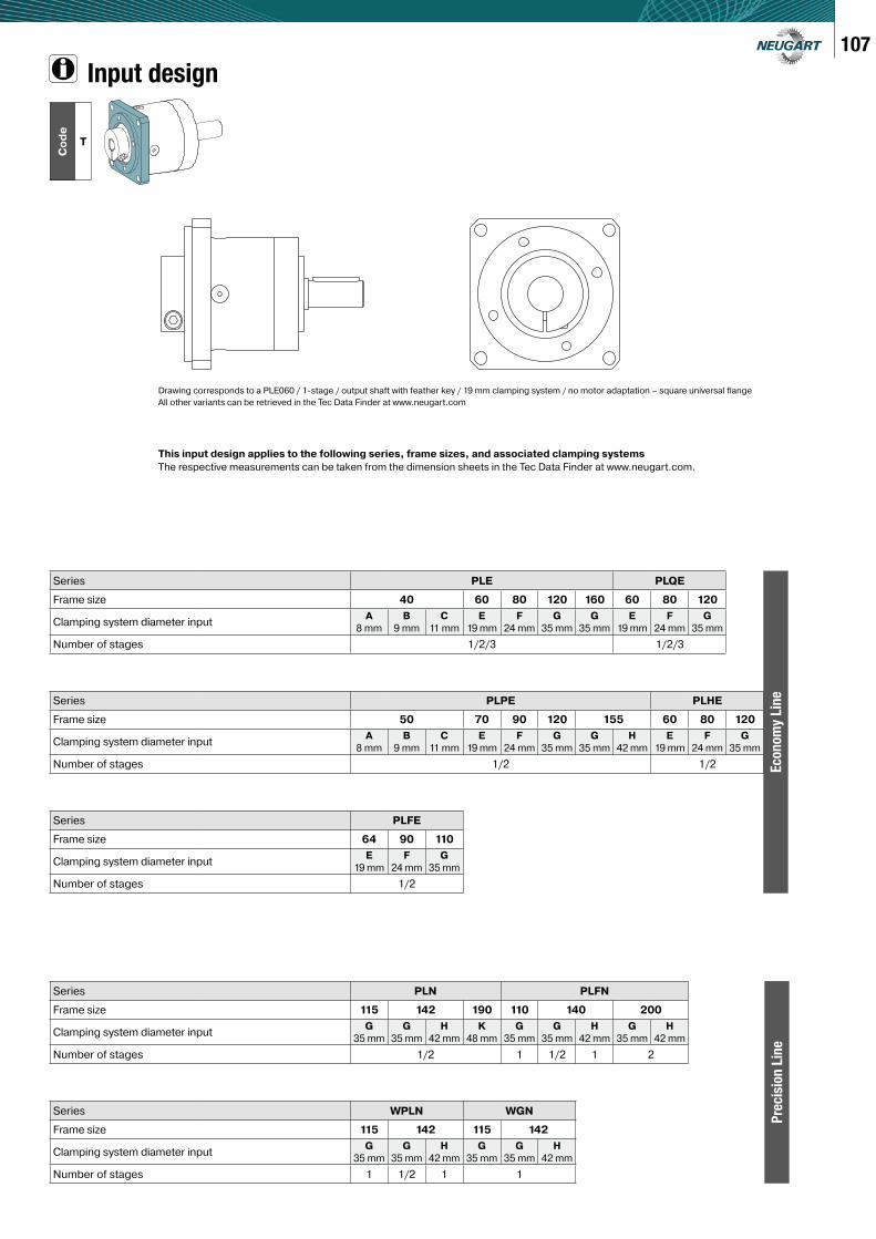
T
Input design
Drawing corresponds to a PLE060 / 1-stage / output shaft with feather key / 19 mm clamping system / no motor adaptation – square universal flange
All other variants can be retrieved in the Tec Data Finder at www.neugart.com
This input design applies to the following series, frame sizes, and associated clamping systems
The respective measurements can be taken from the dimension sheets in the Tec Data Finder at www.neugart.com.
Series PLE PLQE
Frame size 40 60 80 120 160 60 80 120
Clamping system diameter inputA
8 mm
B
9 mm
C
11 mm
E
19 mm
F
24 mm
G
35 mm
G
35 mm
E
19 mm
F
24 mm
G
35 mm
Number of stages 1/2/3 1/2/3
Series PLPE PLHE
Frame size 50 70 90 120 155 60 80 120
Clamping system diameter inputA
8 mm
B
9 mm
C
11 mm
E
19 mm
F
24 mm
G
35 mm
G
35 mm
H
42 mm
E
19 mm
F
24 mm
G
35 mm
Number of stages 1/2 1/2
Series PLFE
Frame size 64 90 110
Clamping system diameter inputE
19 mm
F
24 mm
G
35 mm
Number of stages 1/2
Econ
om
y Lin
e
Series PLN PLFN
Frame size 115 142 190 110 140 200
Clamping system diameter inputG
35 mm
G
35 mm
H
42 mm
K
48 mm
G
35 mm
G
35 mm
H
42 mm
G
35 mm
H
42 mm
Number of stages 1/2 1 1/2 1 2
Series WPLN WGN
Frame size 115 142 115 142
Clamping system diameter inputG
35 mm
G
35 mm
H
42 mm
G
35 mm
G
35 mm
H
42 mm
Number of stages 1 1/2 1 1
Pre
cis
ion
Lin
e
109
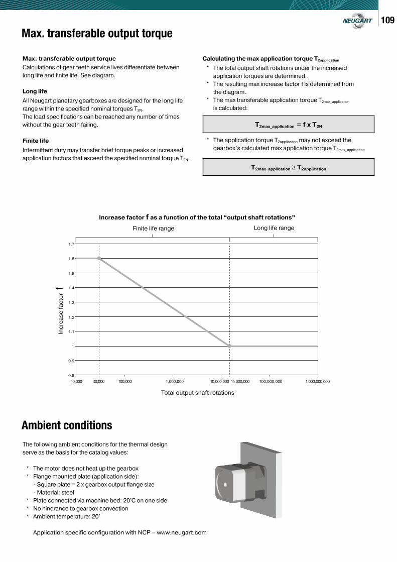
Max. transferable output torque
Max. transferable output torque
Calculations of gear teeth service lives diff erentiate between
long life and fi nite life. See diagram.
Long life
All Neugart planetary gearboxes are designed for the long life
range within the specifi ed nominal torques T2N.
The load specifi cations can be reached any number of times
without the gear teeth failing.
Finite life
Intermittent duty may transfer brief torque peaks or increased
application factors that exceed the specifi ed nominal torque T2N.
Calculating the max application torque T2application
* The total output shaft rotations under the increased
application torques are determined.
* The resulting max increase factor f is determined from
the diagram.
* The max transferable application torque T2max_application
is calculated:
* The application torque T2application may not exceed the
gearbox’s calculated max application torque T2max_application
T2max_application = f x T2N
T2max_application ≥ T2application
The following ambient conditions for the thermal design
serve as the basis for the catalog values:
* The motor does not heat up the gearbox
* Flange mounted plate (application side):
- Square plate = 2 x gearbox output fl ange size
- Material: steel
* Plate connected via machine bed: 20°C on one side
* No hindrance to gearbox convection
* Ambient temperature: 20°
Application specific configuration with NCP – www.neugart.com
Finite life range Long life range
Total output shaft rotations
Inc
rea
se
fa
cto
r f
Increase factor f as a function of the total “output shaft rotations”
Ambient conditions
10,000
0.8
0.9
1.1
1.2
1.3
1.4
1.5
1.6
1.7
1
30,000 100,000 1,000,000 10,000,000 15,000,000 100,000,000 1,000,000,000