Embed Size (px)
Citation preview
Model 45000 Tubing Tong
Installation, Operation, Service and Parts Book Manual
WPI WELLKIN Inc.
8401 Industrial Dr.
Pearland, TX 77584
PH: (281) 992-2064
FX: (281) 992-2076
E-mail: [email protected]
Web: www.wpiwellkin.com
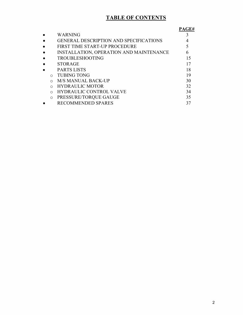
TABLE OF CONTENTS PAGE# WARNING 3 GENERAL DESCRIPTION AND SPECIFICATIONS 4 FIRST TIME START-UP PROCEDURE 5 INSTALLATION, OPERATION AND MAINTENANCE 6 TROUBLESHOOTING 15 STORAGE 17 PARTS LISTS 18 o TUBING TONG 19 o M/S MANUAL BACK-UP 30 o HYDRAULIC MOTOR 32 o HYDRAULIC CONTROL VALVE 34 o PRESSURE/TORQUE GAUGE 35
RECOMMENDED SPARES 37
2
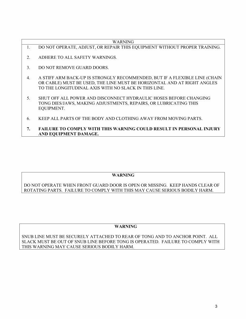
WARNING 1. DO NOT OPERATE, ADJUST, OR REPAIR THIS EQUIPMENT WITHOUT PROPER TRAINING.
2. ADHERE TO ALL SAFETY WARNINGS.
3. DO NOT REMOVE GUARD DOORS.
4. A STIFF ARM BACK-UP IS STRONGLY RECOMMENDED, BUT IF A FLEXIBLE LINE (CHAIN
OR CABLE) MUST BE USED, THE LINE MUST BE HORIZONTAL AND AT RIGHT ANGLES TO THE LONGITUDINAL AXIS WITH NO SLACK IN THIS LINE.
5. SHUT OFF ALL POWER AND DISCONNECT HYDRAULIC HOSES BEFORE CHANGING
TONG DIES/JAWS, MAKING ADJUSTMENTS, REPAIRS, OR LUBRICATING THIS EQUIPMENT.
6. KEEP ALL PARTS OF THE BODY AND CLOTHING AWAY FROM MOVING PARTS.
7. FAILURE TO COMPLY WITH THIS WARNING COULD RESULT IN PERSONAL INJURY
AND EQUIPMENT DAMAGE.
WARNING
DO NOT OPERATE WHEN FRONT GUARD DOOR IS OPEN OR MISSING. KEEP HANDS CLEAR OF ROTATING PARTS. FAILURE TO COMPLY WITH THIS MAY CAUSE SERIOUS BODILY HARM.
WARNING
SNUB LINE MUST BE SECURELY ATTACHED TO REAR OF TONG AND TO ANCHOR POINT. ALL SLACK MUST BE OUT OF SNUB LINE BEFORE TONG IS OPERATED. FAILURE TO COMPLY WITH THIS WARNING MAY CAUSE SERIOUS BODILY HARM.
3
4
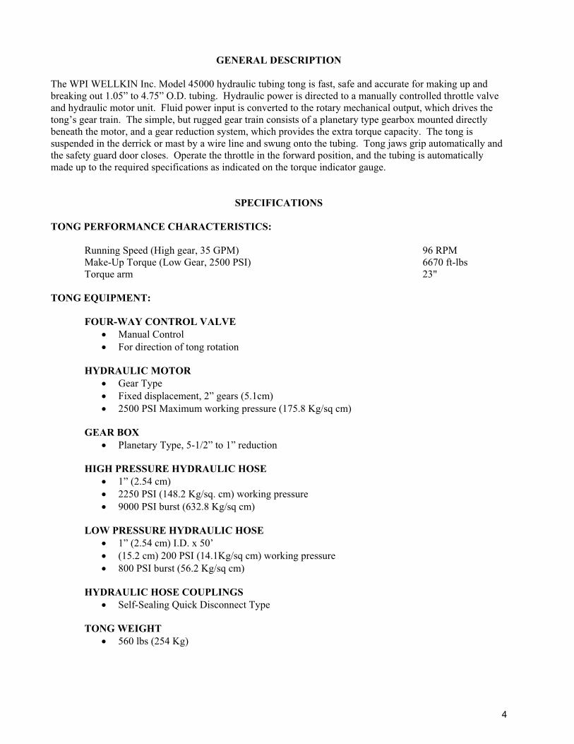
GENERAL DESCRIPTION
The WPI WELLKIN Inc. Model 45000 hydraulic tubing tong is fast, safe and accurate for making up and breaking out 1.05” to 4.75” O.D. tubing. Hydraulic power is directed to a manually controlled throttle valve and hydraulic motor unit. Fluid power input is converted to the rotary mechanical output, which drives the tong’s gear train. The simple, but rugged gear train consists of a planetary type gearbox mounted directly beneath the motor, and a gear reduction system, which provides the extra torque capacity. The tong is suspended in the derrick or mast by a wire line and swung onto the tubing. Tong jaws grip automatically and the safety guard door closes. Operate the throttle in the forward position, and the tubing is automatically made up to the required specifications as indicated on the torque indicator gauge.
SPECIFICATIONS
TONG PERFORMANCE CHARACTERISTICS:
Running Speed (High gear, 35 GPM) 96 RPM Make-Up Torque (Low Gear, 2500 PSI) 6670 ft-lbs Torque arm 23"
TONG EQUIPMENT:
FOUR-WAY CONTROL VALVE � Manual Control � For direction of tong rotation
HYDRAULIC MOTOR � Gear Type � Fixed displacement, 2” gears (5.1cm) � 2500 PSI Maximum working pressure (175.8 Kg/sq cm)
GEAR BOX � Planetary Type, 5-1/2” to 1” reduction
HIGH PRESSURE HYDRAULIC HOSE � 1” (2.54 cm) � 2250 PSI (148.2 Kg/sq. cm) working pressure � 9000 PSI burst (632.8 Kg/sq cm)
LOW PRESSURE HYDRAULIC HOSE � 1” (2.54 cm) I.D. x 50’ � (15.2 cm) 200 PSI (14.1Kg/sq cm) working pressure � 800 PSI burst (56.2 Kg/sq cm)
HYDRAULIC HOSE COUPLINGS � Self-Sealing Quick Disconnect Type
TONG WEIGHT � 560 lbs (254 Kg)
4
FIRST TIME START-UP PROCEDURE The operator should read and follow these instructions before attempting to operate the tongs for the first time. When preparing to operate a new or re-conditioned hydraulic tubing tong, or an assembly that has been in storage, perform all of the operations listed below. Before operating (at the beginning of each shift), perform daily operations in “Lubrication and Preventive Maintenance” procedure. TONG: Clean tong and remove any packing material. Grease, oil, and lubricate brake band. Function test linkage and shift mechanism for free operation. Suspend in derrick. HYDRAULIC HOSES:
1. Adjust hydraulic system pressure to 500 PSI or less.
2. Shift tong to neutral position.
3. Engage hydraulic system clutch.
4. Push throttle lever toward tong
5. Allow hydraulic fluid to circulate with tong gearshift lever in neutral position and the throttle advanced for approximately five minutes.
6. Set system pressure.
7. Check system for leaks.
8. If operating in cold weather, engage tong in high gear and rotate 2-3 minutes for warm-
up. Check tong linkage adjustments.
5
6
INSTALLATION AND MAINTENANCE OF TONG
1. Always wear eye protection prior to replacing dies.
2. Clean dies with wire brush daily to prevent damage to outside of tubing.
3. Inspect and change worn dies periodically to prevent slippage and damage to tubing.
4. Remove jaw and bushing from tong before changing dies.
5. Install dies correctly to ensure gripping on tubing. Dies must be installed with the teeth facing the direction of rotation.
6. Roll pins in jaw and bushing must be installed correctly to prevent dies from falling down well when operating tong.
SUSPENSION OF TONGS IN DERRICK
1. Suspend the tong in the derrick with as long a line as possible, at a height to grip the tubing at least 6” ABOVE THE UPSET. The angle of hanging line from vertical when tongs are on tubing MUST NOT be great enough to pull the tong off the pipe.
2. Attach Back-up line.
a. A Back-up line, automatic or retraction, is attached to the Back-up Ring. The Back-up line must be of sufficient strength and be properly secured. BACK-UP LINE MUST BE HORIZONTAL TO TONG: THAT IS, IT MUST NOT PULL UP OR DOWN ON THE TONG WHILE IN OPERATION. For correct torque readings, the Back-up line MUST BE ON A 90� ANGLE WITH THE TONG.
b. WPI WELLKIN Inc. recommends the use of a safety sling to prevent injury of personnel caused by failure of the main Back-up line or stiff-arm assembly. The safety sling attached to the safety eye on the back of the tong and fastened to the rig or to a secure tie down.
NOTE: A Back-up line must always be used, with or without the coupling Back-up assembly.
9. Connect hydraulic hoses and start power unit.
10. Swing tong on tubing joint. Advance the throttle enough to take the slack out of the Back-up line. This will put the tong in a level position.
6
OPERATING INSTRUCTIONS
Tongs are assembled with parts carefully machined from selected materials. Each tong is thoroughly tested and inspected and is shipped from the factory with confidence that it will efficiently perform any job for which it is rated. The ensuing pages have been prepared for your guidance. These procedures are necessary and should be followed for proper operation and maximum life of your tong. FLUID REQUIREMENTS: To obtain the proper torque in making up and breaking out, the Tubing Tong requires a fluid volume of approximately 35 to 40 gallons per minute (132.5 LPM to 151.4 LPM) at 2000 PSI (70.3 Kg/sq cm) and a minimum of 10 GPM (37.8 LPM) at 1000 to 2000 PSI (70.3 to 140.6 Kg/sq cm). Every effort should be made to keep the hydraulic system clean. The coupling on the tong is self-sealing and should be used whenever the hoses are disconnected. Use of this type of coupling insures the pressure and return hoses, four-way valve, and hydraulic motor being full of oil, minimizing spillage. HOSE CONNECTIONS: When connecting the hoses, ensure there is no pressure in the system. Detach the fluid pump from the engine or shut the whole system down. ALWAYS CONNECT THE 1” (2.54 cm) FLUID RETURN HOSE TO THE TONG FIRST, and then connect the fluid supply hose. ALWAYS DISCONNECT THE FLUID SUPPLY HOSE FIRST. This prevents any pressure from building up in the hydraulic motor and seal. When attaching the hoses to the tong, DUST CAPS SHOULD ALWAYS BE USED WHENEVER HOSES ARE DISCONNECTED. Should the open end of the coupling be allowed to come in contact with any dirt, it should be very carefully cleaned before re-connecting and installing dust caps. A very small amount of dirt, sand, or foreign material can cause serious damage to the pump, hydraulic motor and valves.
7
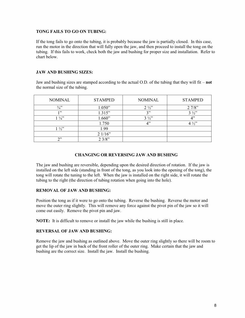
TONG FAILS TO GO ON TUBING: If the tong fails to go onto the tubing, it is probably because the jaw is partially closed. In this case, run the motor in the direction that will fully open the jaw, and then proceed to install the tong on the tubing. If this fails to work, check both the jaw and bushing for proper size and installation. Refer to chart below. JAW AND BUSHING SIZES: Jaw and bushing sizes are stamped according to the actual O.D. of the tubing that they will fit – not the normal size of the tubing.
NOMINAL STAMPED NOMINAL STAMPED
¾” 1.050” 2 ½” 2 7/8” 1” 1.315” 3” 3 ½”
1 ¼” 1.660” 3 ½” 4” 1.750 4” 4 ½”
1 ½” 1.99 2 1/16”
2” 2 3/8”
CHANGING OR REVERSING JAW AND BUSHING
The jaw and bushing are reversible, depending upon the desired direction of rotation. If the jaw is installed on the left side (standing in front of the tong, as you look into the opening of the tong), the tong will rotate the tuning to the left. When the jaw is installed on the right side, it will rotate the tubing to the right (the direction of tubing rotation when going into the hole). REMOVAL OF JAW AND BUSHING: Position the tong as if it were to go onto the tubing. Reverse the bushing. Reverse the motor and move the outer ring slightly. This will remove any force against the pivot pin of the jaw so it will come out easily. Remove the pivot pin and jaw. NOTE: It is difficult to remove or install the jaw while the bushing is still in place. REVERSAL OF JAW AND BUSHING: Remove the jaw and bushing as outlined above. Move the outer ring slightly so there will be room to get the lip of the jaw in back of the front roller of the outer ring. Make certain that the jaw and bushing are the correct size. Install the jaw. Install the bushing.
8
CHANGING THE TUBING TONG BRAKE BAND
Align the opening of the inner and outer rings with the opening in the tong frame. Remove the two cap screws from the brake band cover plate. Apply grease liberally to the lining of the new brake band and to the inside of the eye on each end of the band. Put the new brake band on the inner ring and remove the wooden spacer. If the new brake band does not have a spacer, a piece of wood 5 ½” long can be inserted. The brake band cover can then be closed and the two cap screws installed. NOTE: When the cover plate is down, ensure that the two brake pins in the cover plate enter the eye openings at each end of the brake band.
9
RUNNING THE TONG
*Before operating the tong for the first time, refer to “First Time Start-Up Procedure” MAKING UP THE TUBING With the tong suspended, position gearshift lever (located towards the front of the tong) in high gear. With the safety guard on the front of the tong open, position tong onto the tubing. (The safety guard will automatically close as tubing enters). It is necessary for the tong to be in this position for the jaws to grip. DO NOT SWING THE TONG ONTO THE TUBING TOO HARD, AS IT MAY CAUSE THE TONG TO BOUNCE OFF. Engaging the throttle causes the jaws to grip and rotate the tubing. The pressure at which the pump unit is set determines the make-up torque.
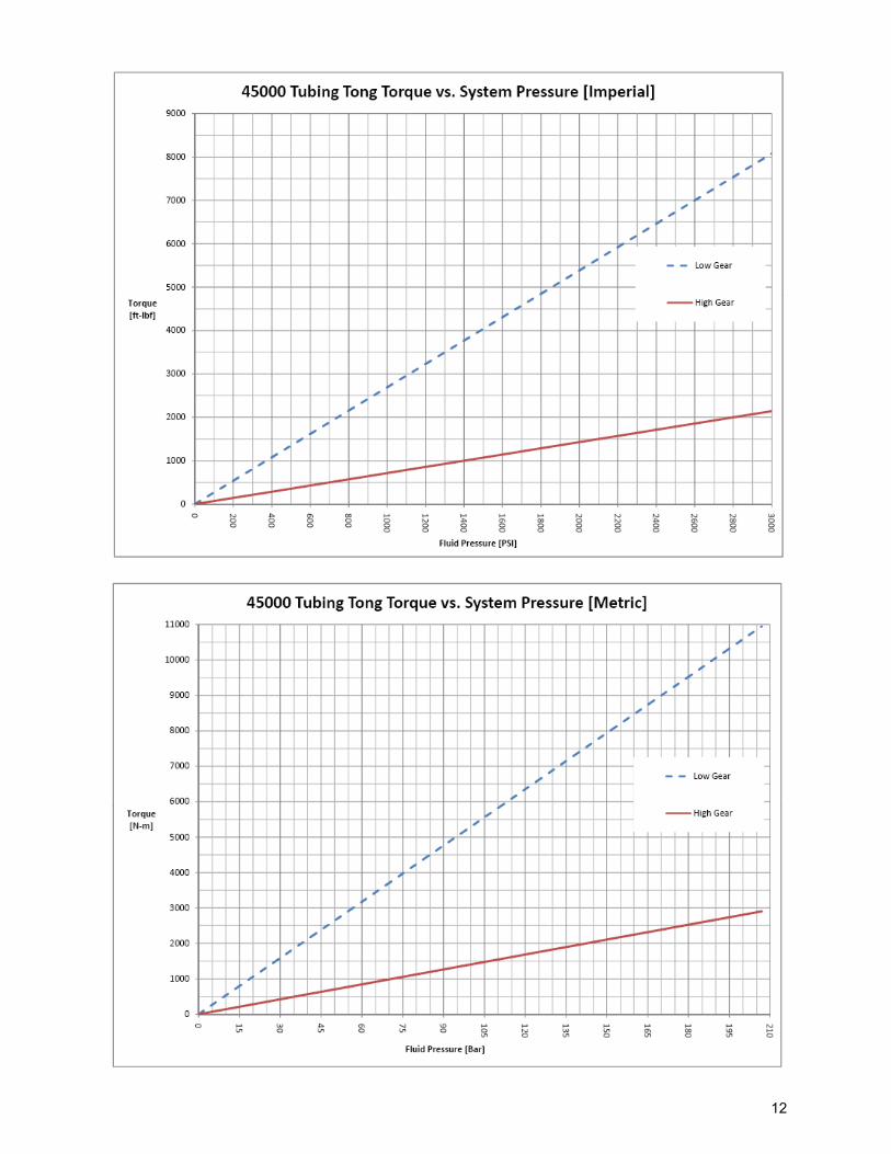
TORQUE CURVE
OIL PRESSURE On high-pressure well, stall pressures should be higher. High torque and critical joints should be made up using the manufacturer’s recommended torque values and taking direct readings from the torque indicator gauge. Accurate readings are also dependent upon proper tong suspension. To release the tongs from the tubing, reverse tong by pushing the throttle back until the gap in the rotor becomes in alignment with that of the case. The jaws will automatically release.
10
11
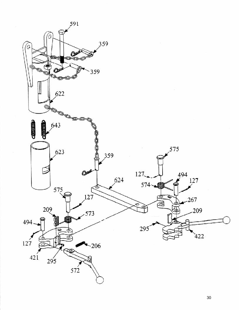
M/S MANUAL BACK-UP ACCESSORY
1. Install manual back-up hanger assembly on tong, insuring that leveling adjustment bolt is to the rear of the tong.
2. Install back-up tool in hanger assembly, place pin and safety clip in lever to secure assembly.
3. To set manual back up for breakout, the lug jaw assembly (Ref. 422) must be positioned on right hand side of back up.
4. To operate back up, position the tong on pipe so that the lug jaw system is gripping. Using both hands, install lever latch in lug jaw assembly in a position to grip tubing coupling. Firmly hold lever latch with one hand, using opposite hand to operate tong throttle. Break out joint, push on lever latch to release.
5. For make-up of tubing, remove lever latch assembly from hanger assembly. Reposition and install so that lug jaw is on left hand side. Position the tong on tubing and grip pipe with jaw system. Install lever latch in lug jaw so that back up will grip on upset below coupling. This will ensure that the coupling is made-up to proper torque.
a. To prevent injury, always grip lever latch loosely with palm of hand. Lever latch and lug jaw may become separated if not fully engaged on teeth of lug jaw when torque is applied to tubing.
b. Use the back-up tong only when necessary. This will minimize wear and reduce labor.
BACK-UP USAGE
The back up should be used during the following conditions:
1. When pulling tubing out of the well and the coupling unscrews from pin on tubing in the well.
2. When weight of pipe becomes light enough to allow pipe to rotate in slips.
3. When running tubing in well until load is significant to prevent tubing from rotating in the slips. To prevent rotating, secure tubing spider to wellhead.
NOTE: When running tubing in the hole, back up must be used: 1. On the upset below the tubing coupling to insure proper make-up of coupling. 2. To prevent string from turning in the slips. 3. To ensure the make-up of both threaded connections.
11
12
TONG LINKAGE ADJUSTMENT
SHIFT ROD ADJUSTMENT Shift rod adjustment is accomplished with jam nuts located on each end of the rod. Adjust gearshift handle in neutral position. THROTTLE ADJUSTMENT The throttle rod adjustment is set with the safety arm and with the door in open position. Adjust safety bar to match the slot in the safety arm and secure by tightening jam nut. NOTE: Proper adjustment allows full throttle in both directions with the door closed and prevents throttling when door is open. GEAR SHIFT TENSION ADJUSTMENT Adjusting gearshift tension is accomplished by turning setscrew in until gears will not shift and backing out setscrew until shifting is smooth. There will be approximately three threads of the setscrew exposed beyond the transmission cover when shifting mechanism is new. Setscrew position is also a wear indicator for the shift rod fork.
HYDRAULIC OIL SPECIFICATION
The hydraulic system fluid affects performance and service life of all other components of a hydraulic system. Some of the factors especially important in the selection of oil for use in a hydraulic system are:
1. The oil must contain the necessary additives to ensure high anti-wear characteristics. Not all hydraulic oils contain these in sufficient amounts.
2. The oil must have proper viscosity to maintain adequate sealing and lubricating quality at
the expected operating temperatures of the hydraulic system.
3. The oil must have rust and oxidation inhibition for satisfactory system operation. Viscosity of fluid is a measure of its resistance to flow as well as its ability to prevent metal-to-metal contact of moving parts. It is recommended that the following maximum and minimum viscosity ranges of the oil at start-up and during running be maintained: Nominal: 150-3000 viscosity at 100 F (38 C) Running: 70-250 viscosity At start-up: 4000 viscosities maximum An anti-wear type of heavy-duty industrial hydraulic oil is recommended. This anti-wear type of oil offers superior protection against pump and motor wear, and has the advantage of long service life. In addition, these oils provide good demulsibility as well as protection against rust. A good grade SAE 20 “MS” automotive crankcase oil can be substituted. For most efficient operation, the temperature of the oil should not exceed 150 F (66 C).
13
GREASE SPECIFICATIONS
Due to the operating environment of the tong, water insoluble grease is required. The grease should have high pump ability to permit application during very cold weather. The grease recommended for cold weather operation is Shell B&B Code 70919, which conforms to Government Specification MIL-G-10924-C. In milder climates, all-purpose grease such as Shell Alvina #2 is recommended.
STEPS TO AVOID CORROSION
Every trip, lubricate all grease fittings with the recommended grease. With an oilcan, lubricate the following: throttle mechanism and the shift mechanism. Lubricate brake band and friction surface with only enough light oil to keep the surface from rusting when the tong is not in service. If the tong does not grip the pipe, the cause may be too much grease on the brake band. This can be remedied by wiping the brake band and friction surfaces clean of all grease, later re-lubricating with grease. The tong should be cleaned periodically or after each shift when used around salt water.
14
IMPORTANT LUBRICATION AND PREVENTIVE MAINTENANCE
To obtain the long life and best performance from a tong, the operator must adhere to the following instructions on lubrication and preventive maintenance. Areas to be oiled or greased, and proper care of the hydraulic hoses and couplings. The daily instructions pertain to routine or daily operation of a tong and not to new equipment. For new tongs, follow instructions given in “First Time Start-Up Procedures”. The time intervals given in the instructions refer to actual hours on the tong. ITEM 1:
After every trip, lubricate the following with 30W oil or equivalent, throttle mechanism shift mechanism, guard door spring, front end of reverse rod and jaw pins.
ITEM 2:
After every trip, all grease fittings should be lubricated with the recommended grease. In addition to those shown, there are fittings on each guide roller shaft, one on the bottom transmission cover and one on the underside of the handle. There is no danger of over-greasing the tong. Under continuous operations, such as when tong is used for light drilling operations, grease the tong every hour.
ITEM 3:
During connecting and disconnecting hoses, inspect couplings to ensure that all openings are free of dirt and debris. Use clean rag and solvent when cleaning, if required. Take proper precautions to ensure that the solvent does not enter hose. Hoses should be wiped clean, and if storage is necessary, install dust covers and store in a clean, warm climate protected from direct sunlight.
15
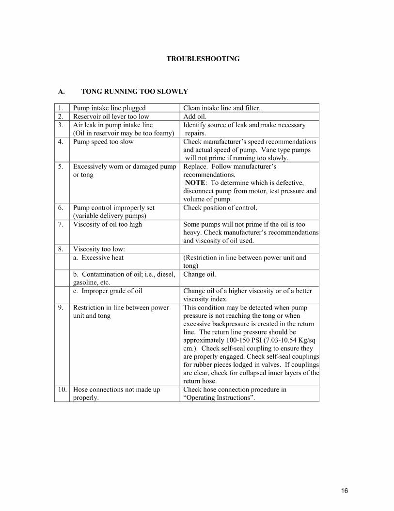
TROUBLESHOOTING
A. TONG RUNNING TOO SLOWLY
1. Pump intake line plugged Clean intake line and filter. 2. Reservoir oil lever too low Add oil. 3. Air leak in pump intake line
(Oil in reservoir may be too foamy) Identify source of leak and make necessary repairs.
4. Pump speed too slow Check manufacturer’s speed recommendations and actual speed of pump. Vane type pumps will not prime if running too slowly.
5. Excessively worn or damaged pump or tong
Replace. Follow manufacturer’s recommendations. NOTE: To determine which is defective, disconnect pump from motor, test pressure and volume of pump.
6. Pump control improperly set (variable delivery pumps)
Check position of control.
7. Viscosity of oil too high Some pumps will not prime if the oil is too heavy. Check manufacturer’s recommendations and viscosity of oil used.
8. Viscosity too low: a. Excessive heat (Restriction in line between power unit and
tong) b. Contamination of oil; i.e., diesel,
gasoline, etc. Change oil.
c. Improper grade of oil Change oil of a higher viscosity or of a better viscosity index.
9. Restriction in line between power unit and tong
This condition may be detected when pump pressure is not reaching the tong or when excessive backpressure is created in the return line. The return line pressure should be approximately 100-150 PSI (7.03-10.54 Kg/sq cm.). Check self-seal coupling to ensure they are properly engaged. Check self-seal couplingsfor rubber pieces lodged in valves. If couplings are clear, check for collapsed inner layers of thereturn hose.
10. Hose connections not made up properly.
Check hose connection procedure in “Operating Instructions”.
16
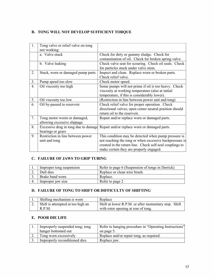
B. TONG WILL NOT DEVELOP SUFFICIENT TORQUE
C. FAILURE OF JAWS TO GRIP TUBING 1. Improper tong suspension Refer to page 6 (Suspension of tongs in Derrick) 2. Dull dies Replace or clean wire brush. 3. Brake band worn Replace. 4. Improper jaw size Refer to page 2 D. FAILURE OF TONG TO SHIFT OR DIFFICULTY OF SHIFTING 1. Shifting mechanism is worn Replace 2. Shift is attempted at too high an
R.P.M. Shift at lower R.P.M. or after momentary stop. Shift with rotor opening at rear of tong.
E. POOR DIE LIFE 1. Improperly suspended tong; tong
hanger bottomed out Refer to hanging procedure in “Operating Instructions”on page 5.
2. Tong worn excessively Replace and/or repair tong, as required. 3. Improperly reconditioned dies Replace jaw.
1. Tong valve or relief valve on tong not working:
a. Valve stuck Check for dirty or gummy sludge. Check for contamination of oil. Check for broken spring valve.
b. Valve leaking Check valve seat for scouring. Check oil seals. Check for particles stuck under valve stem.
2. Stuck, worn or damaged pump parts Inspect and clean. Replace worn or broken parts. Check relief valve.
3. Pump speed too slow Check motor speed. 4. Oil viscosity too high Some pumps will not prime if oil is too heavy. Check
viscosity at working temperature (also at initial temperature, if this is considerably lower).
5. Oil viscosity too low (Restriction in line between power unit and tong) 6. Oil by-passed to reservoir Check relief valve for proper operation. Check
directional valves; open center neutral position should return oil to the reservoir.
7. Tong motor worm or damaged, allowing excessive slippage
Repair and/or replace worn or damaged parts.
8. Excessive drag in tong due to damagebearings or gears
Repair and/or replace worn or damaged parts.
9. Restriction in line between power unit and tong
This condition may be detected when pump pressure is not reaching the tong or when excessive backpressure iscreated in the return line. Check self-seal couplings to make certain they are properly engaged.
17
STORAGE
PREPARING TONG FOR STORAGE: When a tong is to be stored or removed from operation, special precautions should be taken to protect the interior and exterior of the tong from rust accumulation and corrosion. It will be necessary to remove all rust or corrosion completely from any exposed part before applying a rust preventive compound. Therefore, it is recommended that the tong be processed for storage as soon as possible after removal from operation. Storage should be in a building, which is dry and can be heated during the winter months. Moisture absorbing chemicals are available commercially for use when excessive dampness prevails in the storage area. The recommended storage preparation is detailed below. TEMPORARY STORAGE: To protect a tong during storage for periods of 30 days or less: 1. Clean entire exterior of tong with solvent and thoroughly dry. Cleaning is especially important if
unit has been used around salt water. 2. Grease and oil the tong as recommended under “Lubrication and Preventive Maintenance”
procedure. 3. Cover the entire unit with a good weather-resistant tarpaulin or other cover if it must be stored
outdoors. A clear plastic cover is recommended for indoor storage. EXTENDED STORAGE: To protect a tong for storage for periods exceeding 30 days, proceed as follows: 1. Perform Steps 1, 2 and 3 of “Temporary Storage” procedure above. 2. Spray all exterior surfaces of the tong and power unit with a suitable liquid automobile body wax,
a synthetic resin varnish, or a rust preventive compound. 3. Cover the tong and power package with a good weather-resistant tarpaulin or other cover if it
must be stored outdoors. A clear plastic cover is recommended for indoor storage. The stored unit should be inspected periodically. If there are any indications of rust or corrosion, corrective steps must be taken to prevent damage to the parts. Perform a complete inspection at the end of one year and apply additional treatment, as required. For restoring the tong to service, refer to “First Time Start-Up Procedure” on page 4.
18
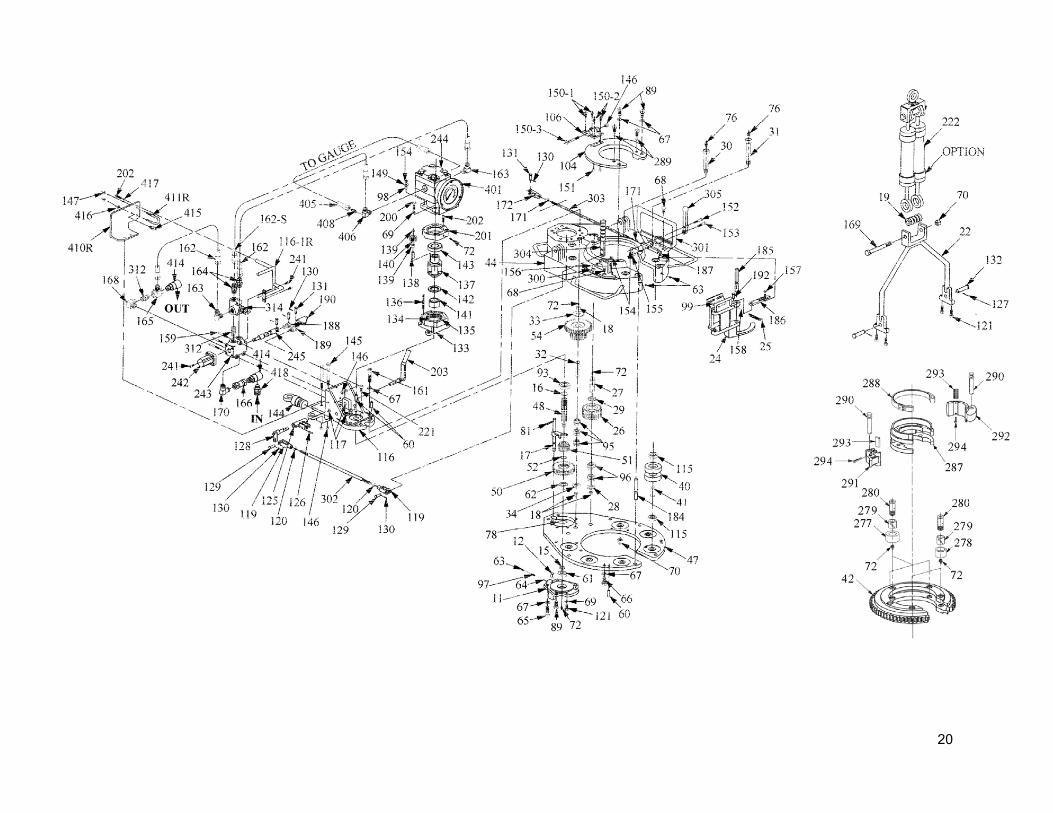
HOW TO ORDER PARTS
When ordering parts for your tubing tong, refer to Parts Lists. Use schematic illustrations to locate correct item number and part number from list. When ordering include: Quantity required Part Number (NOT ITEM NUMBER) Part Name Tong Model Number Tong Serial Number
SAFETY PRECAUTIONS
Your tubing tong has been carefully designed with safety features built into your unit. Realizing, however, that power-driven equipment is only as safe as the operator who is at the controls, it is extremely important that the operator observe the following safety precautions. 1. Operate the tong from the back-up line side only (does not apply to front control tongs). 2. Never change a jaw or put hands within the rotating parts of the tong while tongs are connected to
hydraulic hoses. 3. Never remove or operate the tong without the guard doors in place. 4. Do not exceed the maximum pressure for which this system is rated. 5. Always use a back-up line for all tong operations. 6. Keep loose fitting clothing away from the rotating parts of the tong.
19
20
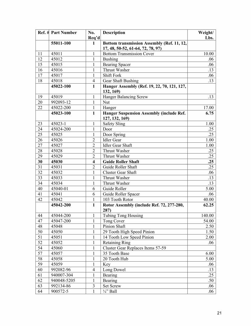
Ref. # Part Number No. Req’d
Description Weight/ Lbs.
55011-100 1 Bottom transmission Assembly (Ref. 11, 12, 17, 48, 50-52, 61-64, 72, 78, 97)
11 45011 1 Bottom Transmission Cover 10.00 12 45012 1 Bushing .06 15 45015 1 Bearing Spacer .06 16 45016 1 Thrust Washer .13 17 45017 1 Shift Fork .06 18 45018 4 Gear Shaft Bushing .13 45022-100 1 Hanger Assembly (Ref. 19, 22, 70, 121, 127,
132, 169)
19 45019 1 Hanger Balancing Screw .13 20 992093-12 1 Nut 22 45022-200 1 Hanger 17.00 45023-100 1 Hanger Suspension Assembly (include Ref.
127, 132, 169) 6.75
23 45023-1 1 Safety Sling 1.00 24 45024-200 1 Door .25 25 45025 1 Door Spring .25 26 45026 2 Idler Gear 1.00 27 45027 2 Idler Gear Shaft 1.00 28 45028 2 Thrust Washer .25 29 45029 2 Thrust Washer .25 30 45030 4 Guide Roller Shaft .25 31 45031 2 Guide Roller Shaft .25 32 45032 1 Cluster Gear Shaft .06 33 45033 1 Thrust Washer .13 34 45034 1 Thrust Washer .13 40 45040-01 6 Guide Roller 5.00 41 45041 6 Guide Roller Spacer .06 42 45042 1 103 Tooth Rotor 40.00 45042-200 1 Rotor Assembly (include Ref. 72, 277-280,
287) 62.25
44 45044-200 1 Tubing Tong Housing 140.00 47 45047-200 1 Tong Cover 54.00 48 45048 1 Pinion Shaft 2.50 50 45050 1 29 Tooth High Speed Pinion 1.50 51 45051 1 14 Tooth Low Speed Pinion 2.00 52 45052 1 Retaining Ring .06 54 45060 1 Cluster Gear Replaces Items 57-59 57 45057 1 35 Tooth Base 6.00 58 45058 1 20 Tooth Hub 5.00 59 45059 1 Key .06 60 992082-96 4 Long Dowel .13 61 940007-304 1 Bearing .25 62 940048-5205 1 Bearing .50 63 992134-86 3 Set Screw .06 64 900572-5 1 ¼” Ball .06
21
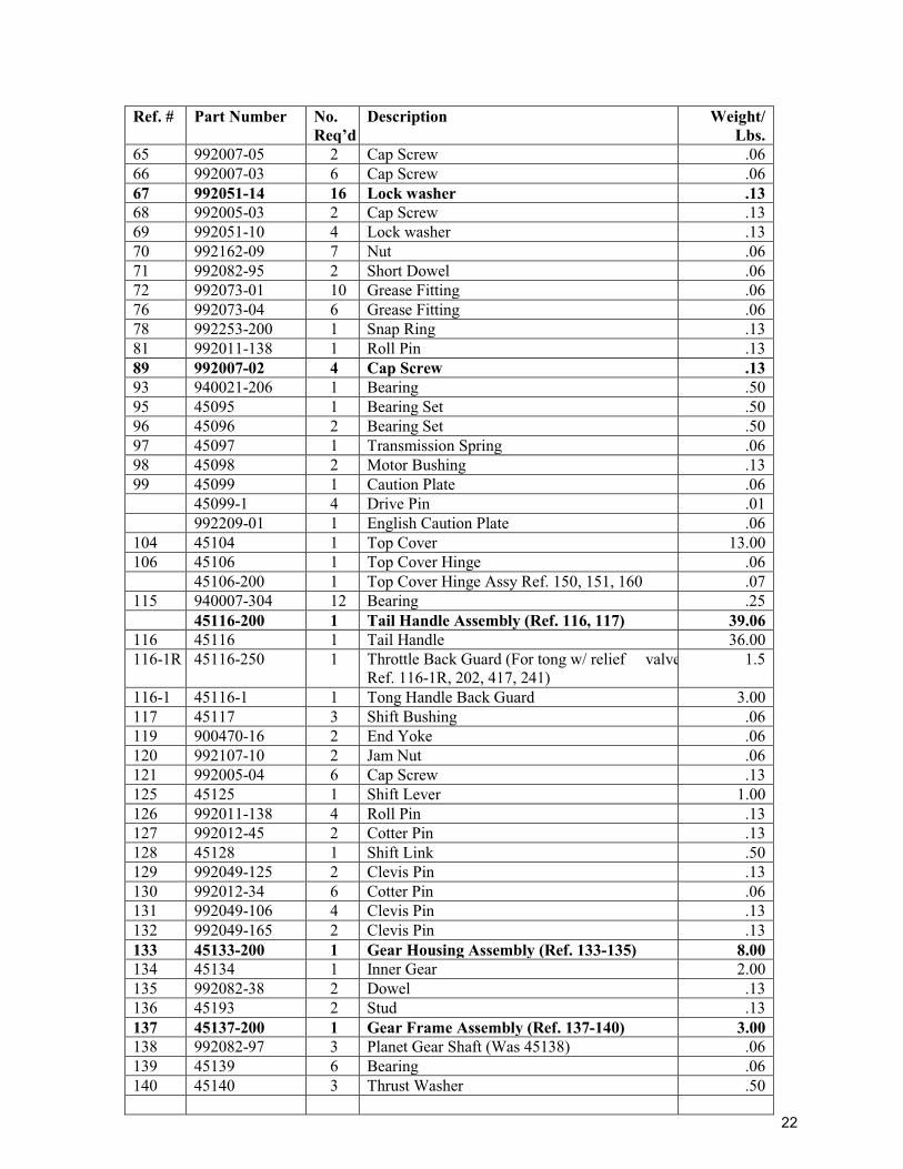
Ref. # Part Number No. Req’d
Description Weight/ Lbs.
65 992007-05 2 Cap Screw .06 66 992007-03 6 Cap Screw .06 67 992051-14 16 Lock washer .13 68 992005-03 2 Cap Screw .13 69 992051-10 4 Lock washer .13 70 992162-09 7 Nut .06 71 992082-95 2 Short Dowel .06 72 992073-01 10 Grease Fitting .06 76 992073-04 6 Grease Fitting .06 78 992253-200 1 Snap Ring .13 81 992011-138 1 Roll Pin .13 89 992007-02 4 Cap Screw .13 93 940021-206 1 Bearing .50 95 45095 1 Bearing Set .50 96 45096 2 Bearing Set .50 97 45097 1 Transmission Spring .06 98 45098 2 Motor Bushing .13 99 45099 1 Caution Plate .06 45099-1 4 Drive Pin .01 992209-01 1 English Caution Plate .06 104 45104 1 Top Cover 13.00 106 45106 1 Top Cover Hinge .06 45106-200 1 Top Cover Hinge Assy Ref. 150, 151, 160 .07 115 940007-304 12 Bearing .25 45116-200 1 Tail Handle Assembly (Ref. 116, 117) 39.06 116 45116 1 Tail Handle 36.00 116-1R 45116-250 1 Throttle Back Guard (For tong w/ relief valve
Ref. 116-1R, 202, 417, 241) 1.5
116-1 45116-1 1 Tong Handle Back Guard 3.00 117 45117 3 Shift Bushing .06 119 900470-16 2 End Yoke .06 120 992107-10 2 Jam Nut .06 121 992005-04 6 Cap Screw .13 125 45125 1 Shift Lever 1.00 126 992011-138 4 Roll Pin .13 127 992012-45 2 Cotter Pin .13 128 45128 1 Shift Link .50 129 992049-125 2 Clevis Pin .13 130 992012-34 6 Cotter Pin .06 131 992049-106 4 Clevis Pin .13 132 992049-165 2 Clevis Pin .13 133 45133-200 1 Gear Housing Assembly (Ref. 133-135) 8.00 134 45134 1 Inner Gear 2.00 135 992082-38 2 Dowel .13 136 45193 2 Stud .13 137 45137-200 1 Gear Frame Assembly (Ref. 137-140) 3.00 138 992082-97 3 Planet Gear Shaft (Was 45138) .06 139 45139 6 Bearing .06 140 45140 3 Thrust Washer .50
22
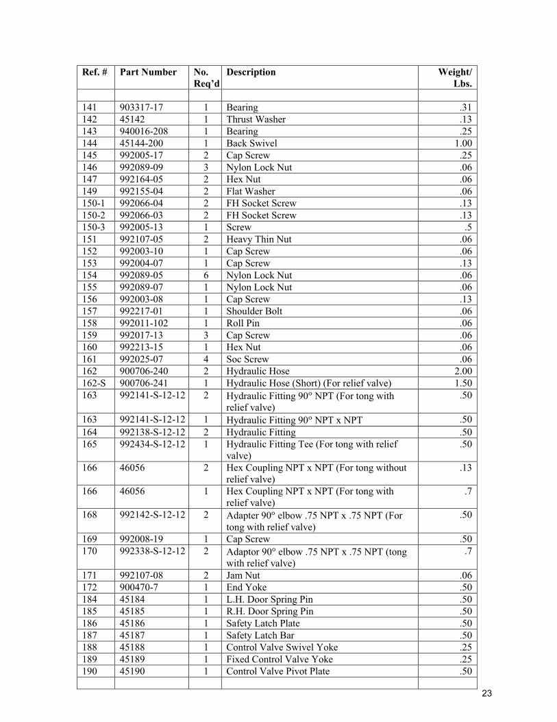
Ref. # Part Number No. Req’d
Description Weight/ Lbs.
141 903317-17 1 Bearing .31 142 45142 1 Thrust Washer .13 143 940016-208 1 Bearing .25 144 45144-200 1 Back Swivel 1.00 145 992005-17 2 Cap Screw .25 146 992089-09 3 Nylon Lock Nut .06 147 992164-05 2 Hex Nut .06 149 992155-04 2 Flat Washer .06 150-1 992066-04 2 FH Socket Screw .13 150-2 992066-03 2 FH Socket Screw .13 150-3 992005-13 1 Screw .5 151 992107-05 2 Heavy Thin Nut .06 152 992003-10 1 Cap Screw .06 153 992004-07 1 Cap Screw .13 154 992089-05 6 Nylon Lock Nut .06 155 992089-07 1 Nylon Lock Nut .06 156 992003-08 1 Cap Screw .13 157 992217-01 1 Shoulder Bolt .06 158 992011-102 1 Roll Pin .06 159 992017-13 3 Cap Screw .06 160 992213-15 1 Hex Nut .06 161 992025-07 4 Soc Screw .06 162 900706-240 2 Hydraulic Hose 2.00 162-S 900706-241 1 Hydraulic Hose (Short) (For relief valve) 1.50 163 992141-S-12-12 2 Hydraulic Fitting 90 NPT (For tong with
relief valve) .50
163 992141-S-12-12 1 Hydraulic Fitting 90 NPT x NPT .50 164 992138-S-12-12 2 Hydraulic Fitting .50 165 992434-S-12-12 1 Hydraulic Fitting Tee (For tong with relief
valve) .50
166 46056 2 Hex Coupling NPT x NPT (For tong without relief valve)
.13
166 46056 1 Hex Coupling NPT x NPT (For tong with relief valve)
.7
168 992142-S-12-12 2 Adapter 90 elbow .75 NPT x .75 NPT (For tong with relief valve)
.50
169 992008-19 1 Cap Screw .50 170 992338-S-12-12 2 Adaptor 90 elbow .75 NPT x .75 NPT (tong
with relief valve) .7
171 992107-08 2 Jam Nut .06 172 900470-7 1 End Yoke .50 184 45184 1 L.H. Door Spring Pin .50 185 45185 1 R.H. Door Spring Pin .50 186 45186 1 Safety Latch Plate .50 187 45187 1 Safety Latch Bar .50 188 45188 1 Control Valve Swivel Yoke .25 189 45189 1 Fixed Control Valve Yoke .25 190 45190 1 Control Valve Pivot Plate .50
23
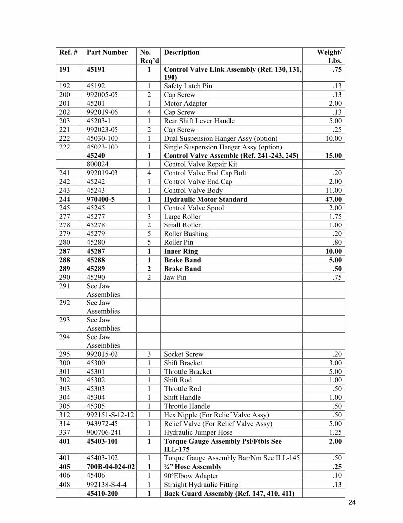
Ref. # Part Number No. Req’d
Description Weight/ Lbs.
191 45191 1 Control Valve Link Assembly (Ref. 130, 131, 190)
.75
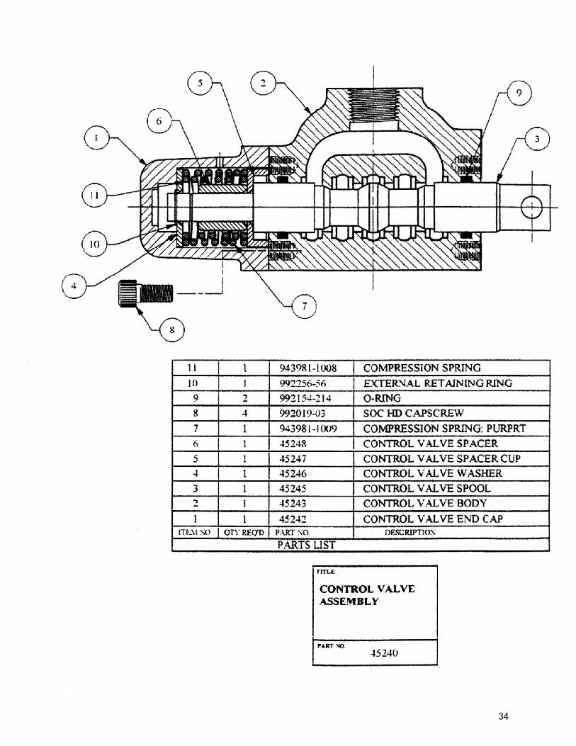
192 45192 1 Safety Latch Pin .13 200 992005-05 2 Cap Screw .13 201 45201 1 Motor Adapter 2.00 202 992019-06 4 Cap Screw .13 203 45203-1 1 Rear Shift Lever Handle 5.00 221 992023-05 2 Cap Screw .25 222 45030-100 1 Dual Suspension Hanger Assy (option) 10.00 222 45023-100 1 Single Suspension Hanger Assy (option) 45240 1 Control Valve Assemble (Ref. 241-243, 245) 15.00 800024 1 Control Valve Repair Kit 241 992019-03 4 Control Valve End Cap Bolt .20 242 45242 1 Control Valve End Cap 2.00 243 45243 1 Control Valve Body 11.00 244 970400-5 1 Hydraulic Motor Standard 47.00 245 45245 1 Control Valve Spool 2.00 277 45277 3 Large Roller 1.75 278 45278 2 Small Roller 1.00 279 45279 5 Roller Bushing .20 280 45280 5 Roller Pin .80 287 45287 1 Inner Ring 10.00 288 45288 1 Brake Band 5.00 289 45289 2 Brake Band .50 290 45290 2 Jaw Pin .75 291 See Jaw
Assemblies
292 See Jaw Assemblies
293 See Jaw Assemblies
294 See Jaw Assemblies
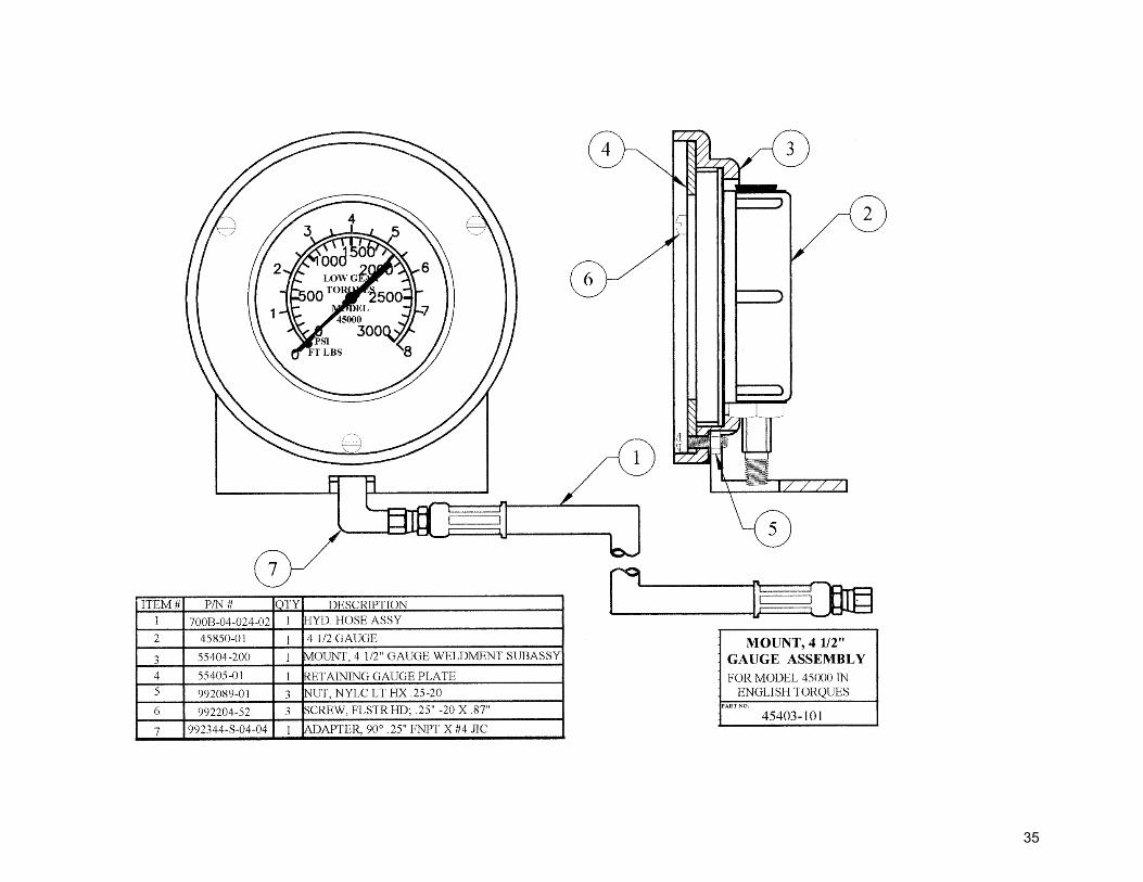
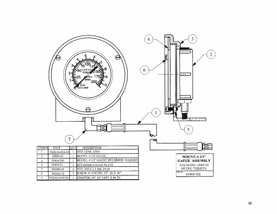
295 992015-02 3 Socket Screw .20 300 45300 1 Shift Bracket 3.00 301 45301 1 Throttle Bracket 5.00 302 45302 1 Shift Rod 1.00 303 45303 1 Throttle Rod .50 304 45304 1 Shift Handle 1.00 305 45305 1 Throttle Handle .50 312 992151-S-12-12 1 Hex Nipple (For Relief Valve Assy) .50 314 943972-45 1 Relief Valve (For Relief Valve Assy) 5.00 337 900706-241 1 Hydraulic Jumper Hose 1.25 401 45403-101 1 Torque Gauge Assembly Psi/Ftbls See
ILL-175 2.00
401 45403-102 1 Torque Gauge Assembly Bar/Nm See ILL-145 .50 405 700B-04-024-02 1 ¼” Hose Assembly .25 406 45406 1 90 Elbow Adapter .10 408 992138-S-4-4 1 Straight Hydraulic Fitting .13 45410-200 1 Back Guard Assembly (Ref. 147, 410, 411)
24
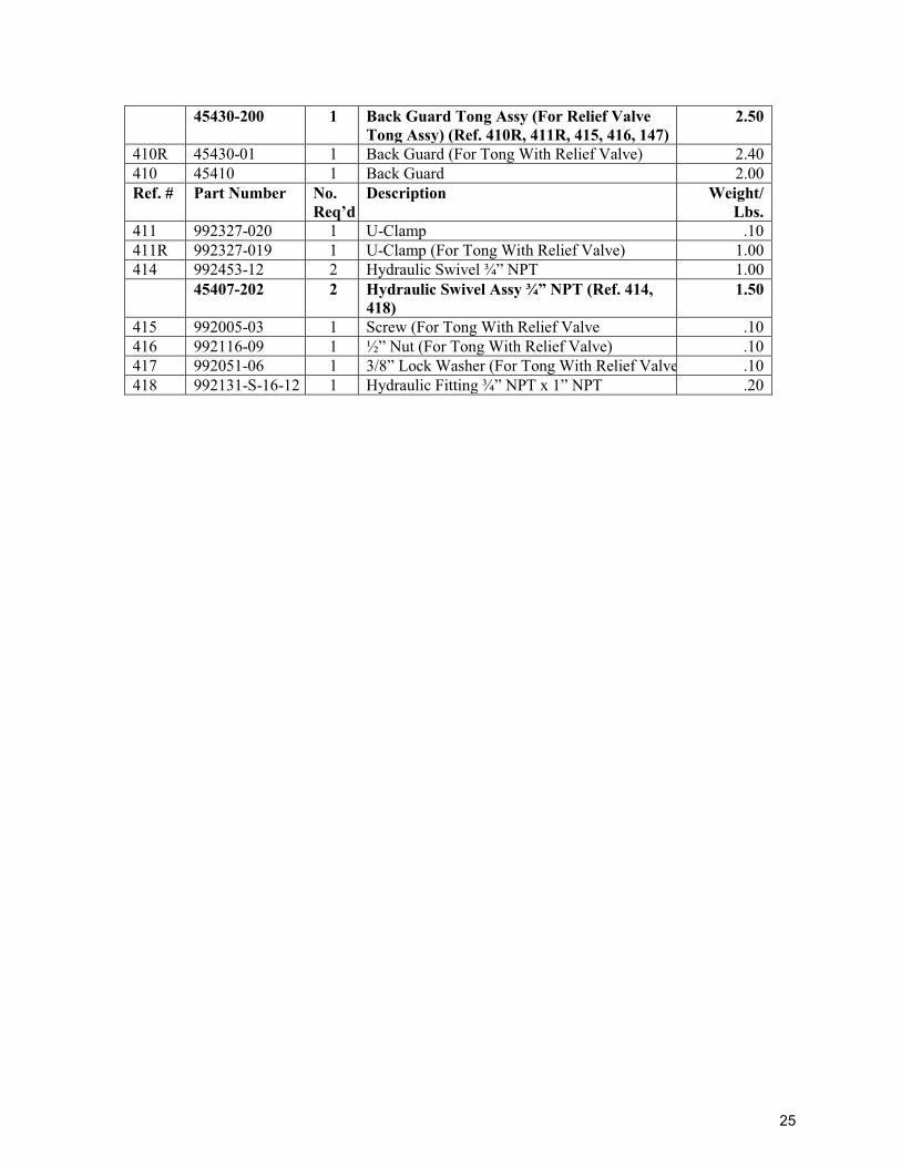
45430-200 1 Back Guard Tong Assy (For Relief Valve Tong Assy) (Ref. 410R, 411R, 415, 416, 147)
2.50
410R 45430-01 1 Back Guard (For Tong With Relief Valve) 2.40 410 45410 1 Back Guard 2.00 Ref. # Part Number No.
Req’d Description Weight/
Lbs. 411 992327-020 1 U-Clamp .10 411R 992327-019 1 U-Clamp (For Tong With Relief Valve) 1.00 414 992453-12 2 Hydraulic Swivel ¾” NPT 1.00 45407-202 2 Hydraulic Swivel Assy ¾” NPT (Ref. 414,
418) 1.50
415 992005-03 1 Screw (For Tong With Relief Valve .10 416 992116-09 1 ½” Nut (For Tong With Relief Valve) .10 417 992051-06 1 3/8” Lock Washer (For Tong With Relief Valve .10 418 992131-S-16-12 1 Hydraulic Fitting ¾” NPT x 1” NPT .20
25
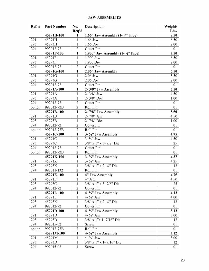
JAW ASSEMBLIES
Ref. # Part Number No. Req’d
Description Weight/Lbs.
45291H-100 1 1.66” Jaw Assembly (1- ¼” Pipe) 8.50291 45291H 1 1.66 Jaw 6.50293 45293H 1 1.66 Die 2.00294 992012-72 2 Cotter Pin .01 45291F-100 1 1.900” Jaw Assembly (1- ½” Pipe) 7.50291 45291F 1 1.900 Jaw 6.50293 45293F 1 1.900 Die 2.00294 992012-72 2 Cotter Pin .01 45291G-100 1 2.06” Jaw Assembly 6.50291 45291G 1 2.06 Jaw 5.50293 45293G 1 2.06 Die 2.00294 992012-72 2 Cotter Pin .01 45291A-100 1 2- 3/8” Jaw Assembly 5.50291 45291A 1 2- 3/8” Jaw 4.50293 45293A 1 2- 3/8” Die 1.00294 992012-72 2 Cotter Pin .01option 992012-72B 2 Roll Pin .01 45291B-100 1 2- 7/8” Jaw Assembly 5.50291 45291B 1 2- 7/8” Jaw 4.50293 45293B 1 2- 7/8” Die 1.00294 992012-72 2 Cotter Pin .01option 992012-72B 2 Roll Pin .01 45291C-100 1 3- ½” Jaw Assembly 4.75291 45291C 1 3- ½” Jaw 4.50293 45293C 1 3/8” x 1” x 3- 7/8” Die .25294 992012-72 2 Cotter Pin .01option 992012-72B 2 Roll Pin .01 45291K-100 1 3- ¾” Jaw Assembly 4.37291 45291K 1 3- ¾” Jaw 4.25293 45293K 1 3/8” x 1” x 2- ¼” Die .12294 992011-132 2 Roll Pin .01 45291E-100 1 4” Jaw Assembly 4.75291 45291E 1 4” Jaw 4.50293 45293C 1 3/8” x 1” x 3- 7/8” Die .25294 992012-72 2 Cotter Pin .01 45291L-100 1 4- ¼” Jaw Assembly 4.12291 45291L 1 4- ¼” Jaw 4.00293 45293K 1 3/8” x 1” x 2- ¼” Die .12294 992012-72 2 Cotter Pin .01 45291D-100 1 4- ½” Jaw Assembly 3.12291 45291D 1 4- ½” Jaw 3.00293 45293D 1 3/8” x 1”x 1- 7/16” Die .12294 992015-02 1 Screw .01option 992012-72B 2 Roll Pin .01 45291M-100 1 4- ¾” Jaw Assembly 3.12291 45291M 1 4- ¾” Jaw 3.00293 45293D 1 3/8” x 1” x 1- 7/16” Die .12294 992015-02 1 Screw .01
26
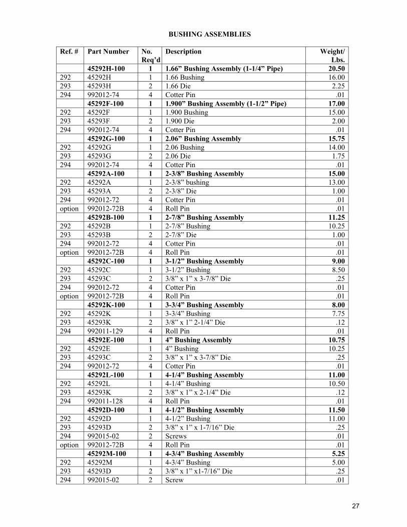
BUSHING ASSEMBLIES
Ref. # Part Number No. Req’d
Description Weight/Lbs.
45292H-100 1 1.66” Bushing Assembly (1-1/4” Pipe) 20.50292 45292H 1 1.66 Bushing 16.00293 45293H 2 1.66 Die 2.25294 992012-74 4 Cotter Pin .01 45292F-100 1 1.900” Bushing Assembly (1-1/2” Pipe) 17.00292 45292F 1 1.900 Bushing 15.00293 45293F 2 1.900 Die 2.00294 992012-74 4 Cotter Pin .01 45292G-100 1 2.06” Bushing Assembly 15.75292 45292G 1 2.06 Bushing 14.00293 45293G 2 2.06 Die 1.75294 992012-74 4 Cotter Pin .01 45292A-100 1 2-3/8” Bushing Assembly 15.00292 45292A 1 2-3/8” bushing 13.00293 45293A 2 2-3/8” Die 1.00294 992012-72 4 Cotter Pin .01option 992012-72B 4 Roll Pin .01 45292B-100 1 2-7/8” Bushing Assembly 11.25292 45292B 1 2-7/8” Bushing 10.25293 45293B 2 2-7/8” Die 1.00294 992012-72 4 Cotter Pin .01option 992012-72B 4 Roll Pin .01 45292C-100 1 3-1/2” Bushing Assembly 9.00292 45292C 1 3-1/2” Bushing 8.50293 45293C 2 3/8” x 1” x 3-7/8” Die .25294 992012-72 4 Cotter Pin .01option 992012-72B 4 Roll Pin .01 45292K-100 1 3-3/4” Bushing Assembly 8.00292 45292K 1 3-3/4” Bushing 7.75293 45293K 2 3/8” x 1” 2-1/4” Die .12294 992011-129 4 Roll Pin .01 45292E-100 1 4” Bushing Assembly 10.75292 45292E 1 4” Bushing 10.25293 45293C 2 3/8” x 1” x 3-7/8” Die .25294 992012-72 4 Cotter Pin .01 45292L-100 1 4-1/4” Bushing Assembly 11.00292 45292L 1 4-1/4” Bushing 10.50293 45293K 2 3/8” x 1” x 2-1/4” Die .12294 992011-128 4 Roll Pin .01 45292D-100 1 4-1/2” Bushing Assembly 11.50292 45292D 1 4-1/2” Bushing 11.00293 45293D 2 3/8” x 1” x 1-7/16” Die .25294 992015-02 2 Screws .01option 992012-72B 4 Roll Pin .01 45292M-100 1 4-3/4” Bushing Assembly 5.25292 45292M 1 4-3/4” Bushing 5.00293 45293D 2 3/8” x 1” x1-7/16” Die .25294 992015-02 2 Screw .01
27
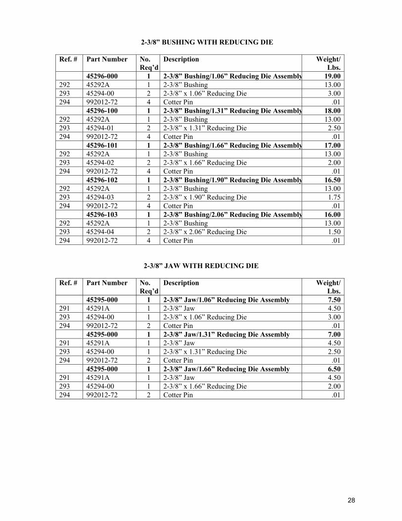
2-3/8” BUSHING WITH REDUCING DIE
Ref. # Part Number No. Req’d
Description Weight/Lbs.
45296-000 1 2-3/8” Bushing/1.06” Reducing Die Assembly 19.00292 45292A 1 2-3/8” Bushing 13.00293 45294-00 2 2-3/8” x 1.06” Reducing Die 3.00294 992012-72 4 Cotter Pin .01 45296-100 1 2-3/8” Bushing/1.31” Reducing Die Assembly 18.00292 45292A 1 2-3/8” Bushing 13.00293 45294-01 2 2-3/8” x 1.31” Reducing Die 2.50294 992012-72 4 Cotter Pin .01 45296-101 1 2-3/8” Bushing/1.66” Reducing Die Assembly 17.00292 45292A 1 2-3/8” Bushing 13.00293 45294-02 2 2-3/8” x 1.66” Reducing Die 2.00294 992012-72 4 Cotter Pin .01 45296-102 1 2-3/8” Bushing/1.90” Reducing Die Assembly 16.50292 45292A 1 2-3/8” Bushing 13.00293 45294-03 2 2-3/8” x 1.90” Reducing Die 1.75294 992012-72 4 Cotter Pin .01 45296-103 1 2-3/8” Bushing/2.06” Reducing Die Assembly 16.00292 45292A 1 2-3/8” Bushing 13.00293 45294-04 2 2-3/8” x 2.06” Reducing Die 1.50294 992012-72 4 Cotter Pin .01
2-3/8” JAW WITH REDUCING DIE
Ref. # Part Number No. Req’d
Description Weight/Lbs.
45295-000 1 2-3/8” Jaw/1.06” Reducing Die Assembly 7.50291 45291A 1 2-3/8” Jaw 4.50293 45294-00 1 2-3/8” x 1.06” Reducing Die 3.00294 992012-72 2 Cotter Pin .01 45295-000 1 2-3/8” Jaw/1.31” Reducing Die Assembly 7.00291 45291A 1 2-3/8” Jaw 4.50293 45294-00 1 2-3/8” x 1.31” Reducing Die 2.50294 992012-72 2 Cotter Pin .01 45295-000 1 2-3/8” Jaw/1.66” Reducing Die Assembly 6.50291 45291A 1 2-3/8” Jaw 4.50293 45294-00 1 2-3/8” x 1.66” Reducing Die 2.00294 992012-72 2 Cotter Pin .01
28
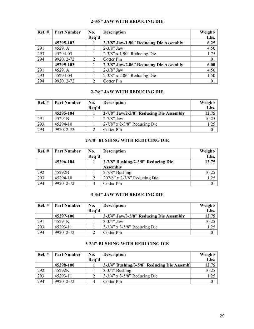
2-3/8” JAW WITH REDUCING DIE
Ref. # Part Number No. Req’d
Description Weight/Lbs.
45295-102 1 2-3/8” Jaw/1.90” Reducing Die Assembly 6.25291 45291A 1 2-3/8” Jaw 4.50293 45294-03 1 2-3/8” x 1.90” Reducing Die 1.75294 992012-72 2 Cotter Pin .01 45295-103 1 2-3/8” Jaw/2.06” Reducing Die Assembly 6.00291 45291A 1 2-3/8” Jaw 4.50293 45294-04 1 2-3/8” x 2.06” Reducing Die 1.50294 992012-72 2 Cotter Pin .01
2-7/8” JAW WITH REDUCING DIE
Ref. # Part Number No. Req’d
Description Weight/Lbs.
45295-104 1 2-7/8” Jaw/2-3/8” Reducing Die Assembly 12.75291 45291B 1 2-7/8” Jaw 10.25293 45294-10 1 2-7/8” x 2-3/8” Reducing Die 1.25294 992012-72 2 Cotter Pin .01
2-7/8” BUSHING WITH REDUCING DIE
Ref. # Part Number No. Req’d
Description Weight/Lbs.
45296-104 1 2-7/8” Bushing/2-3/8” Reducing Die Assembly
12.75
292 45292B 1 2-7/8” Bushing 10.25293 45294-10 2 207/8” x 2-3/8” Reducing Die 1.25294 992012-72 4 Cotter Pin .01
3-3/4” JAW WITH REDUCING DIE
Ref. # Part Number No. Req’d
Description Weight/Lbs.
45297-100 1 3-3/4” Jaw/3-5/8” Reducing Die Assembly 12.75291 45291K 1 3-3/4” Jaw 10.25293 45293-11 1 3-3/4” x 3-5/8” Reducing Die 1.25294 992012-72 2 Cotter Pin .01
3-3/4” BUSHING WITH REDUCING DIE
Ref. # Part Number No. Req’d
Description Weight/Lbs.
45298-100 1 3-3/4” Bushing/3-5/8” Reducing Die Assembly 12.75292 45292K 1 3-3/4” Bushing 10.25293 45293-11 2 3-3/4” x 3-5/8” Reducing Die 1.25294 992012-72 4 Cotter Pin .01
29
30
31
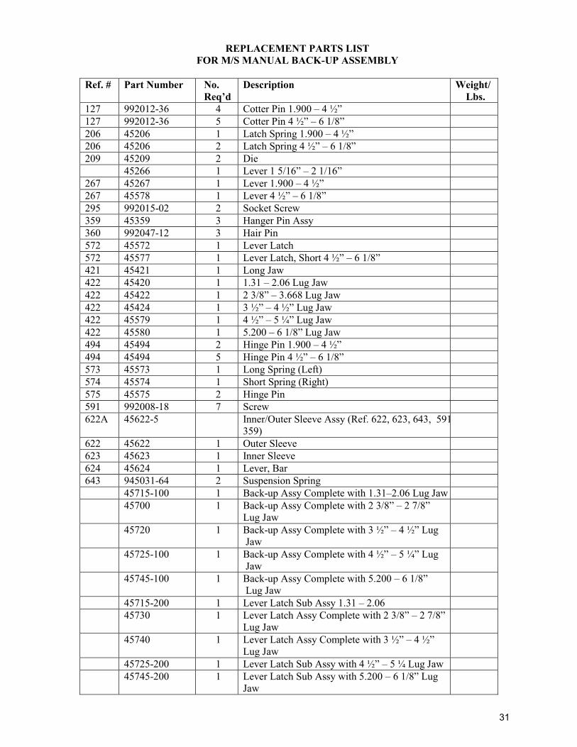
REPLACEMENT PARTS LIST FOR M/S MANUAL BACK-UP ASSEMBLY
Ref. # Part Number No.
Req’d Description Weight/
Lbs. 127 992012-36 4 Cotter Pin 1.900 – 4 ½” 127 992012-36 5 Cotter Pin 4 ½” – 6 1/8” 206 45206 1 Latch Spring 1.900 – 4 ½” 206 45206 2 Latch Spring 4 ½” – 6 1/8” 209 45209 2 Die 45266 1 Lever 1 5/16” – 2 1/16” 267 45267 1 Lever 1.900 – 4 ½” 267 45578 1 Lever 4 ½” – 6 1/8” 295 992015-02 2 Socket Screw 359 45359 3 Hanger Pin Assy 360 992047-12 3 Hair Pin 572 45572 1 Lever Latch 572 45577 1 Lever Latch, Short 4 ½” – 6 1/8” 421 45421 1 Long Jaw 422 45420 1 1.31 – 2.06 Lug Jaw 422 45422 1 2 3/8” – 3.668 Lug Jaw 422 45424 1 3 ½” – 4 ½” Lug Jaw 422 45579 1 4 ½” – 5 ¼” Lug Jaw 422 45580 1 5.200 – 6 1/8” Lug Jaw 494 45494 2 Hinge Pin 1.900 – 4 ½” 494 45494 5 Hinge Pin 4 ½” – 6 1/8” 573 45573 1 Long Spring (Left) 574 45574 1 Short Spring (Right) 575 45575 2 Hinge Pin 591 992008-18 7 Screw 622A 45622-5 Inner/Outer Sleeve Assy (Ref. 622, 623, 643, 591
359)
622 45622 1 Outer Sleeve 623 45623 1 Inner Sleeve 624 45624 1 Lever, Bar 643 945031-64 2 Suspension Spring 45715-100 1 Back-up Assy Complete with 1.31–2.06 Lug Jaw 45700 1 Back-up Assy Complete with 2 3/8” – 2 7/8”
Lug Jaw
45720 1 Back-up Assy Complete with 3 ½” – 4 ½” Lug Jaw
45725-100 1 Back-up Assy Complete with 4 ½” – 5 ¼” Lug Jaw
45745-100 1 Back-up Assy Complete with 5.200 – 6 1/8” Lug Jaw
45715-200 1 Lever Latch Sub Assy 1.31 – 2.06 45730 1 Lever Latch Assy Complete with 2 3/8” – 2 7/8”
Lug Jaw
45740 1 Lever Latch Assy Complete with 3 ½” – 4 ½” Lug Jaw
45725-200 1 Lever Latch Sub Assy with 4 ½” – 5 ¼ Lug Jaw 45745-200 1 Lever Latch Sub Assy with 5.200 – 6 1/8” Lug
Jaw
31
32
32
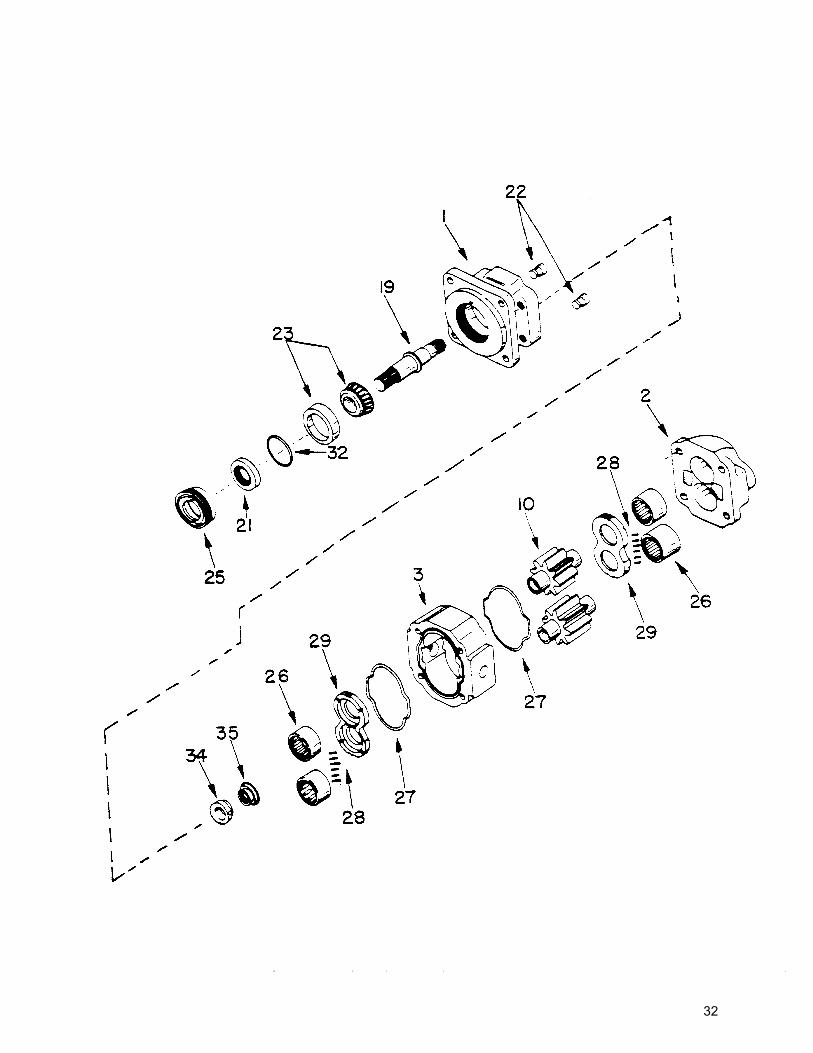
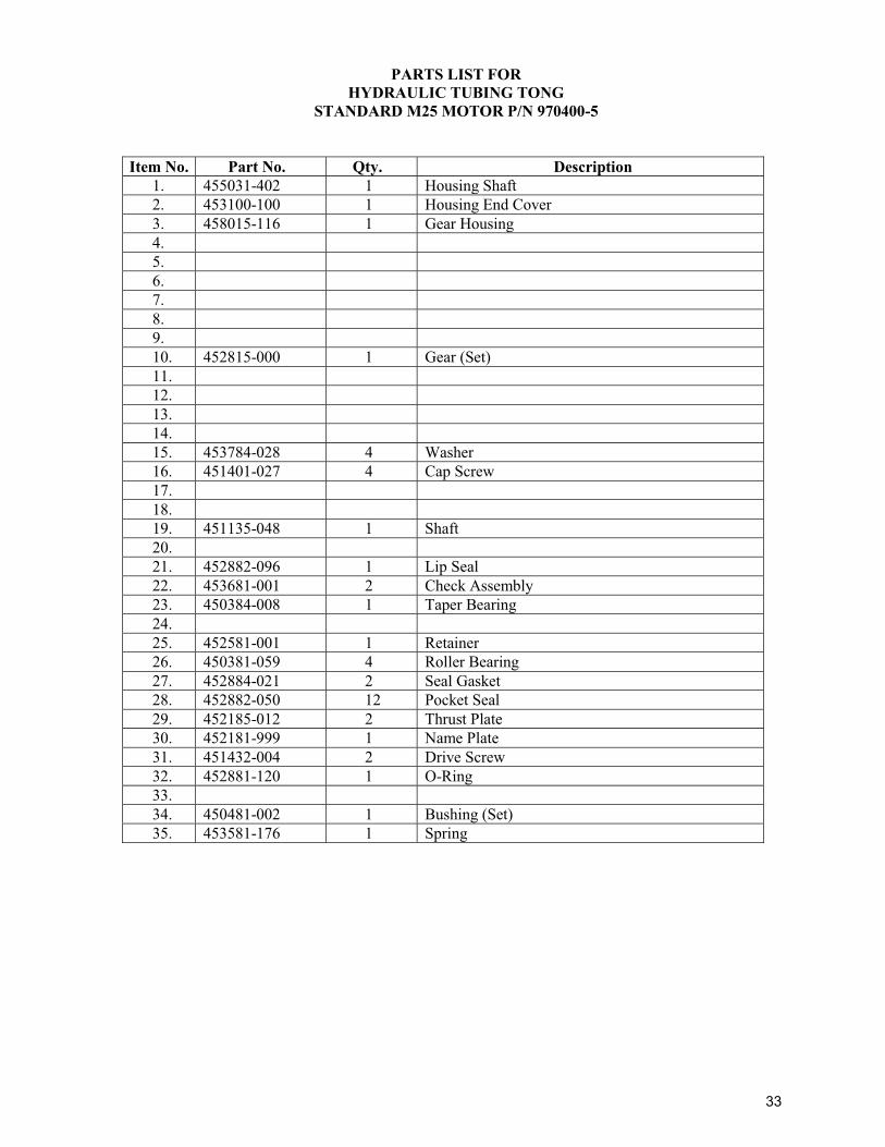
PARTS LIST FOR HYDRAULIC TUBING TONG
STANDARD M25 MOTOR P/N 970400-5 (ILLUSTRATION 008)
Item No. Part No. Qty. Description
1. 455031-402 1 Housing Shaft 2. 453100-100 1 Housing End Cover 3. 458015-116 1 Gear Housing 4. 5. 6. 7. 8. 9. 10. 452815-000 1 Gear (Set) 11. 12. 13. 14. 15. 453784-028 4 Washer 16. 451401-027 4 Cap Screw 17. 18. 19. 451135-048 1 Shaft 20. 21. 452882-096 1 Lip Seal 22. 453681-001 2 Check Assembly 23. 450384-008 1 Taper Bearing 24. 25. 452581-001 1 Retainer 26. 450381-059 4 Roller Bearing 27. 452884-021 2 Seal Gasket 28. 452882-050 12 Pocket Seal 29. 452185-012 2 Thrust Plate 30. 452181-999 1 Name Plate 31. 451432-004 2 Drive Screw 32. 452881-120 1 O-Ring 33. 34. 450481-002 1 Bushing (Set) 35. 453581-176 1 Spring
33
34
62
35
63
36
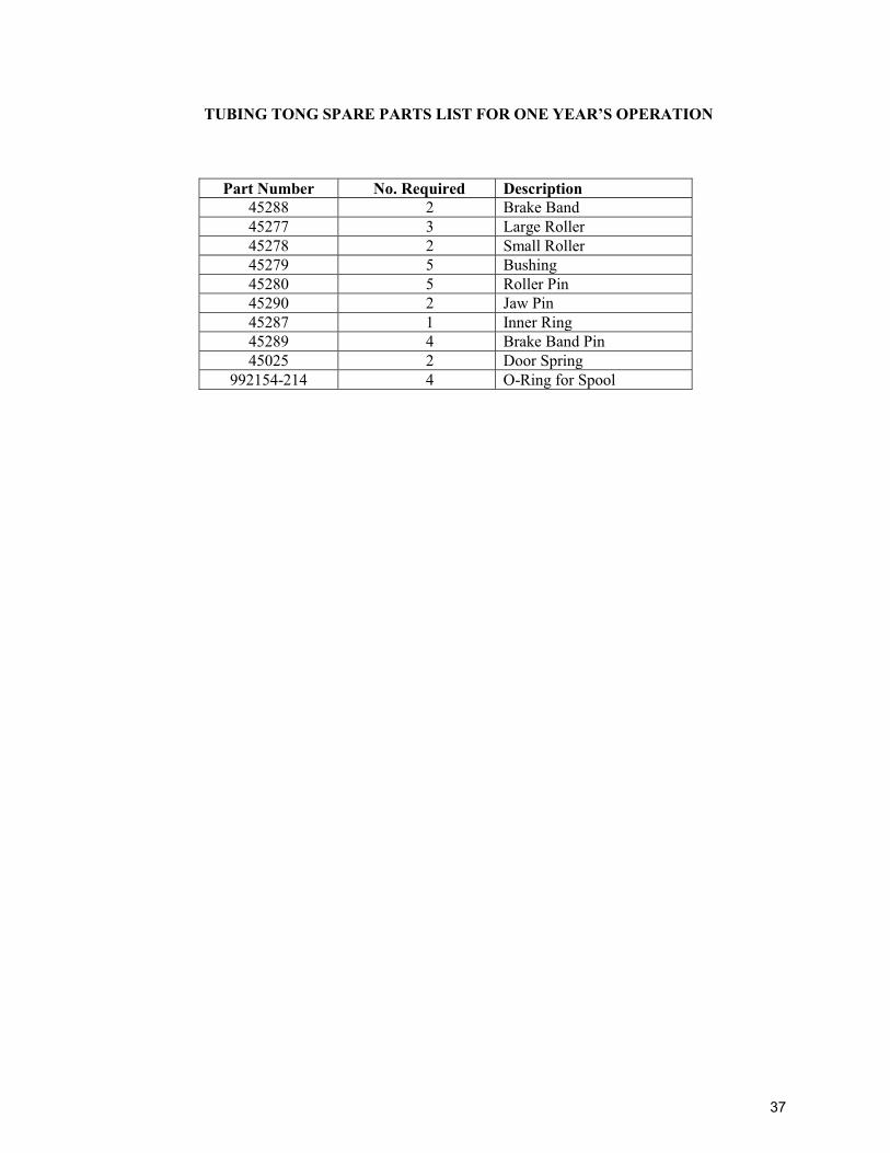
TUBING TONG SPARE PARTS LIST FOR ONE YEAR’S OPERATION
Part Number No. Required Description
45288 2 Brake Band 45277 3 Large Roller 45278 2 Small Roller 45279 5 Bushing 45280 5 Roller Pin 45290 2 Jaw Pin 45287 1 Inner Ring 45289 4 Brake Band Pin 45025 2 Door Spring
992154-214 4 O-Ring for Spool
37
1
8401 Industrial Drive, Pearland, TX 77584
Phone: (281) 992-2064, Fax: (281) 992-2076
E-Mail: [email protected]
Web: www.wpiwellkin.com
WPI WELLKIN Inc. (WPI WELLKIN) Terms and Conditions
1. All WPI WELLKIN packing slips and invoices must show Buyer's purchase order number.
2. All shipments MUST contain packing slips.
3. CONTRACT: This order will become a binding contract upon receipt by WPI WELLKIN of Buyer's
PO, receipt by Buyer of a written acknowledgement by WPI WELLKIN and receipt by WPI WELLKIN of a
down payment in the amount specified in the contract.
4. This contract may be modified as mutually agreed by the Buyer and WPI WELLKIN.
5. PAYMENT TERMS: The payment terms are specified on the commercial offer from WPI
WELLKIN. The Buyer agrees to the payment terms by acceptance of the bid.
6. DELIVERY: Time is of the essence. WPI WELLKIN will attempt to deliver the material early if
possible. WPI WELLKIN will make best efforts to supply all material on a timely basis. If the delivery
will run over the contract delivery date, WPI WELLKIN will notify the Buyer giving reason for delay.
The current delivery estimate is specified on the commercial offer. The Buyer agrees to the delivery
terms by acceptance of the bid.
When necessary, WPI WELLKIN will notify the Buyer in advance of completion of the order and Buyer
will appoint an authorized representative or employee to inspect the material on a date and site as
designated by WPI WELLKIN. Transportation, lodging and all other expenses portal to portal for Buyer
representative or employee to witness and accept the material is the expense of the Buyer.
All costs associated with preparation, crating, insurance and ocean freight of the goods to the final
destination to be at Buyer's expense.
7. CANCELLATION: This contract is considered to be special order and not subject to cancellation.
Both parties hereto shall be given consideration in case of delays in delivery caused by fire, strike, riot,
war, act of God, delay of carriers, governmental order or regulation, complete or partial shutdown of
plant by reason of inability to obtain sufficient raw materials or power or any other similar or different
contingency beyond the reasonable control of the respective parties.
8. WARRANTIES AND REMEDIES: WPI WELLKIN expressly warrants that all supplies, materials and
parts covered by this contract will conform to the specifications in the contract as applicable and will
meet or exceed industry standards for such equipment. WPI WELLKIN will supply Buyer with
operations manuals and parts books for the material where applicable. Certificates of Compliance are
available upon request.
MANUFACTURED ITEMS: WPI WELLKIN manufactured items must be free of material and
workmanship defects for a period of 6 months from the date of delivery. If any items fail because
of a manufacturing defect within that period of time, then that item will be replaced by WPI
WELLKIN. Expendable / wear items are not covered under warranty. Examples of such items
include, but are not limited to, the following - dies, inserts, brake bands, rollers, gears, chains,
filters, belts, flexible couplings, slip bodies, spider bowls.
2
8401 Industrial Drive, Pearland, TX 77584
Phone: (281) 992-2064, Fax: (281) 992-2076
E-Mail: [email protected]
Web: www.wpiwellkin.com
Replacement of parts will be accomplished at WPI WELLKIN's facility or at a designated service
point. WPI WELLKIN's liability is limited to replacement of defective parts only and does not
include the cost of labor, communications, transportation or handling connected to the
replacement of these parts. WPI WELLKIN will in no event be liable for consequential damages
or contingent liabilities arising out of the failure of any parts to operate properly. No expressed,
implied or statutory guarantee other than herein set forth is made or authorized to be made by
WPI WELLKIN.
DISTRIBUTED ITEMS: Items distributed by WPI WELLIN are subject to the warranty provided by
the Original Equipment Manufacturer (OEM). Upon request, WPI WELLKIN will furnish Buyer
with a warranty statement from the OEM for the applicable material. The OEM warranty will
start on the items' delivery date.
9. COMMISSIONING: On request, WPI WELLKIN can supply a representative for material
commissioning. The Buyer is responsible for portal to portal transportation costs and the current WPI
WELLKIN day rate.
10. BUYER’S PROPERTY: All equipment or material furnished by WPI WELLKIN shall be the
property of the Buyer after the WPI WELLKIN invoice is paid in full.
11. PATENTS: WPI WELLKIN holds the Buyer harmless from all claims, for infringement or alleged
infringement of any patents arising out of the sale or use of the goods furnished pursuant to this
contract.
12. INDEPENDENT CONTRACT: In the event that any goods ordered hereunder require in
connection with the installation thereof, the services of a contractor engaged by WPI WELLKIN or a
supervisor, engineer, or other employee connected with or employed by WPI WELLKIN, and WPI
WELLKIN agrees to furnish same, either with or without charge, such contractor, supervisor, engineer,
or other employee in performing such services shall not be deemed to be the agent or employee of the
Buyer.
13. INSURANCE: WPI WELLKIN agrees to carry General Operations and Liability Insurance and
other coverage as required in accordance with applicable state and federal laws of the U.S.A.
14. COMPLIANCE WITH LAWS: WPI WELLKIN warrants that in its performance of this contract it
will comply with all applicable Federal, State and Local laws, regulations, rulings and orders of the U.S.A.
15. ASSIGNMENT: This contract may not be assigned without the written consent of the Buyer and
any attempted assignment thereof shall be void.
16. PROPRIETARY INFORMATION: All plans, drawings, specification and the subject matter
contained therein and all other information given to WPI WELLKIN in connection with performance on
this Purchase Order involve valuable property rights of the Buyer and shall be held confidential by WPI
WELLKIN, shall remain the property of the Buyer and shall not be used by WPI WELLKIN for any
purpose other than those for which they have been prepared or supplied. WPI WELLKIN agrees that, as
far as possible, it will keep confidential the making of this order and the terms hereof. WPI WELLKIN
agrees not to use for publicity purposes any information as to notice of receipt of order, photographs,
drawings and/or materials in connection with performance of the Order without obtaining the prior
written consent of the Buyer.