Embed Size (px)
Citation preview
79-15224-00 Rev. B3 www.srsmith.com Page 1 of 15
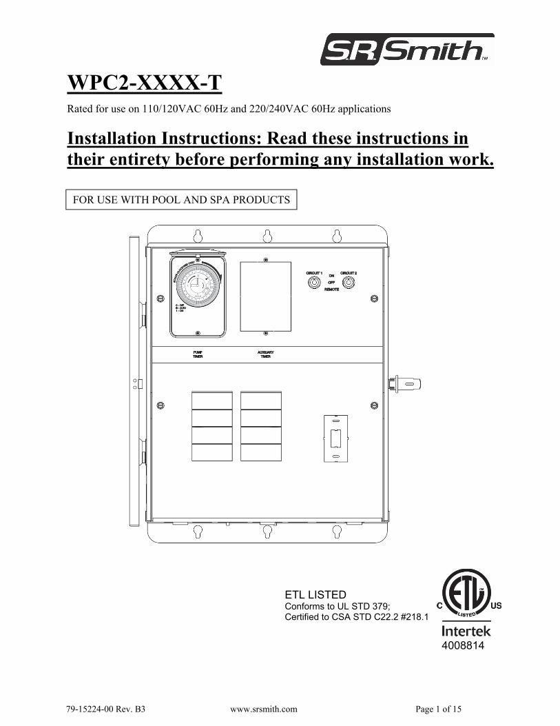
Rated for use on 110/120VAC 60Hz and 220/240VAC 60Hz applications
Installation Instructions: Read these instructions in their entirety before performing any installation work.
FOR USE WITH POOL AND SPA PRODUCTS
4008814
ETL LISTED Conforms to UL STD 379; Certified to CSA STD C22.2 #218.1
WPC2-XXXX-T
79-15224-00 Rev. B3 www.srsmith.com Page 2 of 15
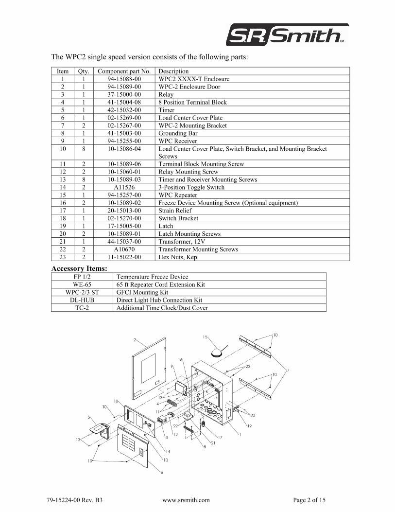
The WPC2 single speed version consists of the following parts:
Item Qty. Component part No. Description 1 1 94-15088-00 WPC2 XXXX-T Enclosure 2 1 94-15089-00 WPC-2 Enclosure Door 3 1 37-15000-00 Relay 4 1 41-15004-08 8 Position Terminal Block 5 1 42-15032-00 Timer 6 1 02-15269-00 Load Center Cover Plate 7 2 02-15267-00 WPC-2 Mounting Bracket 8 1 41-15003-00 Grounding Bar 9 1 94-15255-00 WPC Receiver
10 8 10-15086-04 Load Center Cover Plate, Switch Bracket, and Mounting Bracket Screws
11 2 10-15089-06 Terminal Block Mounting Screw 12 2 10-15060-01 Relay Mounting Screw 13 8 10-15089-03 Timer and Receiver Mounting Screws 14 2 A11526 3-Position Toggle Switch 15 1 94-15257-00 WPC Repeater 16 2 10-15089-02 Freeze Device Mounting Screw (Optional equipment) 17 1 20-15013-00 Strain Relief 18 1 02-15270-00 Switch Bracket 19 1 17-15005-00 Latch 20 2 10-15089-01 Latch Mounting Screws 21 1 44-15037-00 Transformer, 12V 22 2 A10670 Transformer Mounting Screws 23 2 11-15022-00 Hex Nuts, Kep
Accessory Items: FP 1/2 Temperature Freeze Device WE-65 65 ft Repeater Cord Extension Kit
WPC-2/3 ST GFCI Mounting Kit DL-HUB Direct Light Hub Connection Kit
TC-2 Additional Time Clock/Dust Cover
79-15224-00 Rev. B3 www.srsmith.com Page 3 of 15
DANGER – FAILURE TO FOLLOW THESE WARNINGS, INSTRUCTIONS AND THE OWNER’S MANUAL MAY RESULT IN SERIOUS INJURY OR DEATH
Basic safety precautions should be observed when operating the WPC-2 product and other associated equipment. 1. A qualified electrician must install the WPC-2 in accordance to the National and Local Electrical
Codes. 2. The WPC-2 must not be less than 5 feet (3 meters in Canada) from inside edge of pool. ONLY
USE COPPER CONDUCTORS. 3. Do not exceed the maximum ratings of individual components, wiring devices, and current
carrying capacity of conductors. 4. For the bonding, grounding, installing, and wiring of underwater lights to the WPC-2, refer to
Article 680 of the National Electrical Code or Article 68 of the Canadian Electrical Code. 5. This device should never operate equipment that could cause property damage, bodily injury, or
death should it be activated unexpectedly. 6. Never allow children to operate the WPC-2 unsupervised.
IMPORTANT SAFETY INFORMATION
SAVE THESE INSTRUCTIONS!
FCC WARNING 1. This device complies with Part 15 of the FCC Rules. Operation is subject to the following two
conditions: (1) this device may not cause harmful interference, and (2) this device must accept any interference received, including interference that may cause undesired operation.
2. Changes or modifications not expressly approved by S.R. Smith could void the user's authority to operate the equipment.
79-15224-00 Rev. B3 www.srsmith.com Page 4 of 15
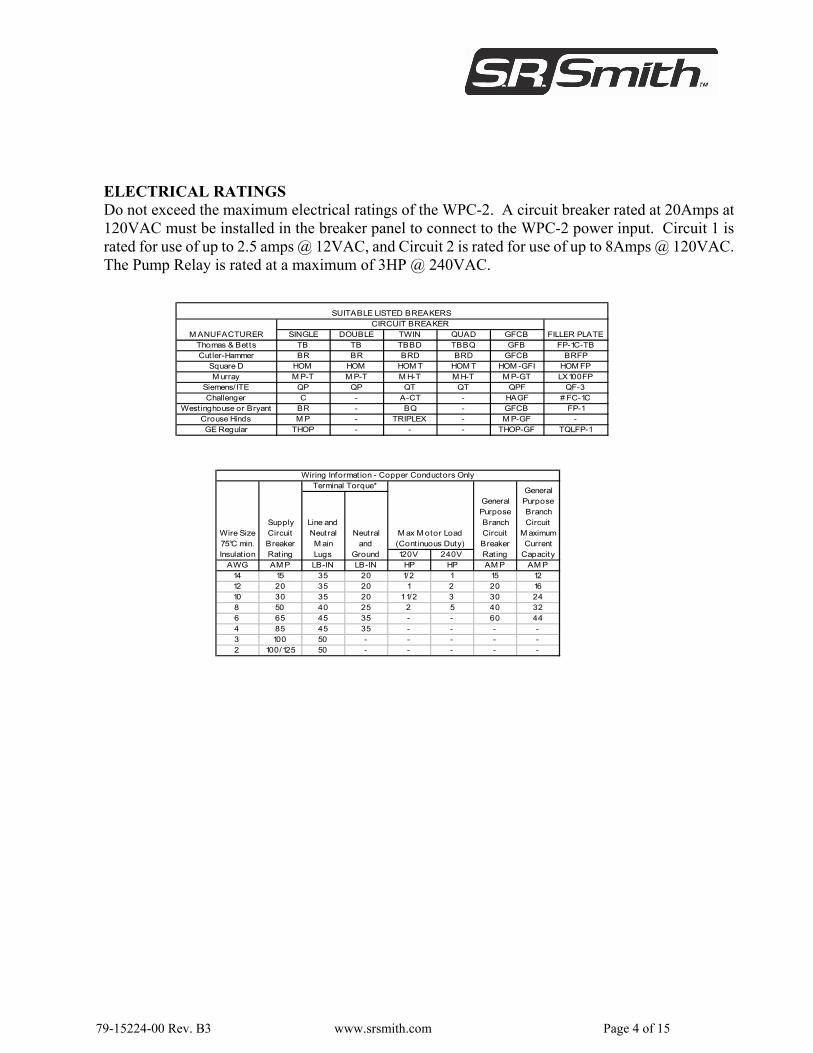
ELECTRICAL RATINGS Do not exceed the maximum electrical ratings of the WPC-2. A circuit breaker rated at 20Amps at 120VAC must be installed in the breaker panel to connect to the WPC-2 power input. Circuit 1 is rated for use of up to 2.5 amps @ 12VAC, and Circuit 2 is rated for use of up to 8Amps @ 120VAC. The Pump Relay is rated at a maximum of 3HP @ 240VAC.
SINGLE DOUBLE TWIN QUAD GFCBThomas & Betts TB TB TBBD TBBQ GFB FP-1C-TBCut ler-Hammer BR BR BRD BRD GFCB BRFP
Square D HOM HOM HOM T HOM T HOM -GFI HOM FPM urray M P-T M P-T M H-T M H-T M P-GT LX100FP
Siemens/ITE QP QP QT QT QPF QF-3Challenger C - A-CT - HAGF # FC-1C
Westinghouse or Bryant BR - BQ - GFCB FP-1Crouse Hinds M P - TRIPLEX - M P-GF -GE Regular THOP - - - THOP-GF TQLFP-1
SUITABLE LISTED BREAKERSCIRCUIT BREAKER
M ANUFACTURER FILLER PLATE
120V 240VAWG AM P LB-IN LB-IN HP HP AM P AM P
14 15 35 20 1/2 1 15 1212 20 35 20 1 2 20 1610 30 35 20 1 1/2 3 30 248 50 40 25 2 5 40 326 65 45 35 - - 60 444 85 45 35 - - - -3 100 50 - - - - -2 100/125 50 - - - - -
General Purpose Branch Circuit Breaker Rating
General Purpose Branch Circuit
M aximum Current
Capacity
Wiring Informat ion - Copper Conductors OnlyTerminal Torque*
Wire Size 75°C min. Insulat ion
Supply Circuit Breaker Rating
Line and Neutral M ain Lugs
Neutral and
Ground
M ax M otor Load (Cont inuous Duty)
79-15224-00 Rev. B3 www.srsmith.com Page 5 of 15
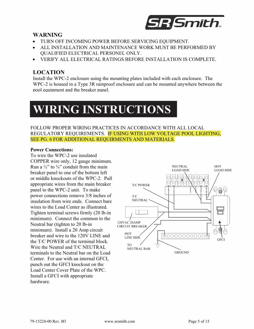
WARNING TURN OFF INCOMING POWER BEFORE SERVICING EQUIPMENT. ALL INSTALLATION AND MAINTENANCE WORK MUST BE PERFORMED BY
QUALIFIED ELECTRICAL PERSONEL ONLY. VERIFY ALL ELECTRICAL RATINGS BEFORE INSTALLATION IS COMPLETE.
FOLLOW PROPER WIRING PRACTICES IN ACCORDANCE WITH ALL LOCAL REGULATORY REQUIREMENTS. IF USING WITH LOW VOLTAGE POOL LIGHTING,SEE PG. 6 FOR ADDITIONAL REQUIRMENTS AND MATERIALS.
WIRING INSTRUCTIONS
LOCATION Install the WPC-2 enclosure using the mounting plates included with each enclosure. The WPC-2 is housed in a Type 3R rainproof enclosure and can be mounted anywhere between the pool equipment and the breaker panel.
Power Connections: To wire the WPC-2 use insulated COPPER wire only, 12 gauge minimum.Run a ½” to ¾” conduit from the main breaker panel to one of the bottom left or middle knockouts of the WPC-2. Pull appropriate wires from the main breaker panel to the WPC-2 unit. To make power connections remove 3/8 inches of insulation from wire ends. Connect bare wires to the Load Center as illustrated. Tighten terminal screws firmly (20 lb-in minimum). Connect the common to the Neutral bar (tighten to 20 lb-in minimum). Install a 20 Amp circuit breaker and wire to the 120V LINE and the T/C POWER of the terminal block. Wire the Neutral and T/C NEUTRAL terminals to the Neutral bar on the Load Center. For use with an internal GFCI, punch out the GFCI knockout on the Load Center Cover Plate of the WPC. Install a GFCI with appropriate hardware.
TO NEUTRAL BAR
HOT LINE SIDE
GROUND
T/C NEUTRAL
T/C POWER
HOT LOAD SIDE
NEUTRAL LOAD SIDE
GFCI
120VAC 20AMP CIRCUIT BREAKER
79-15224-00 Rev. B3 www.srsmith.com Page 6 of 15
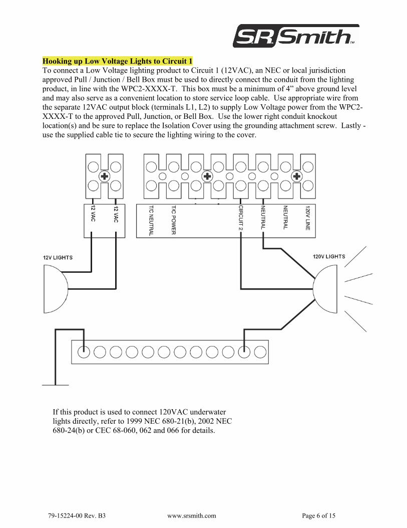
Hooking up Low Voltage Lights to Circuit 1 To connect a Low Voltage lighting product to Circuit 1 (12VAC), an NEC or local jurisdiction approved Pull / Junction / Bell Box must be used to directly connect the conduit from the lighting product, in line with the WPC2-XXXX-T. This box must be a minimum of 4” above ground level and may also serve as a convenient location to store service loop cable. Use appropriate wire from the separate 12VAC output block (terminals L1, L2) to supply Low Voltage power from the WPC2-XXXX-T to the approved Pull, Junction, or Bell Box. Use the lower right conduit knockout location(s) and be sure to replace the Isolation Cover using the grounding attachment screw. Lastly -use the supplied cable tie to secure the lighting wiring to the cover.
If this product is used to connect 120VAC underwater lights directly, refer to 1999 NEC 680-21(b), 2002 NEC 680-24(b) or CEC 68-060, 062 and 066 for details.
79-15224-00 Rev. B3 www.srsmith.com Page 7 of 15
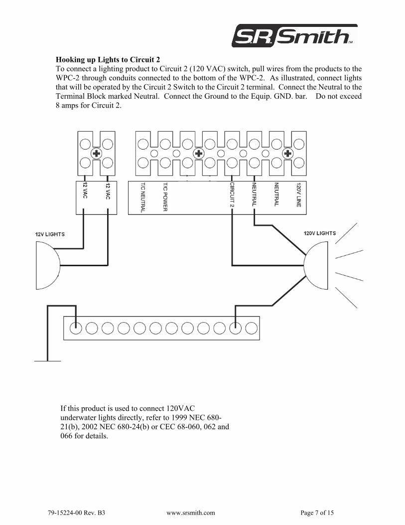
Hooking up Lights to Circuit 2 To connect a lighting product to Circuit 2 (120 VAC) switch, pull wires from the products to theWPC-2 through conduits connected to the bottom of the WPC-2. As illustrated, connect lights that will be operated by the Circuit 2 Switch to the Circuit 2 terminal. Connect the Neutral to the Terminal Block marked Neutral. Connect the Ground to the Equip. GND. bar. Do not exceed8 amps for Circuit 2.
If this product is used to connect 120VAC underwater lights directly, refer to 1999 NEC 680-21(b), 2002 NEC 680-24(b) or CEC 68-060, 062 and 066 for details.
79-15224-00 Rev. B3 www.srsmith.com Page 8 of 15
PUMP CONNECTIONS
NOTE: Some models are ONLY equipped with Single Speed OR Dual Speed pump connections.
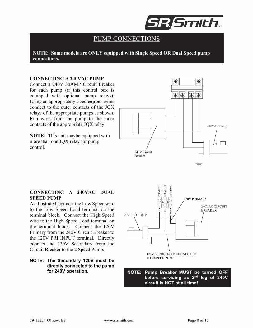
CONNECTING A 240VAC PUMP Connect a 240V 30AMP Circuit Breakerfor each pump (if this control box isequipped with optional pump relays).Using an appropriately sized copper wires connect to the outer contacts of the JQXrelays of the appropriate pumps as shown.Run wires from the pump to the innercontacts of the appropriate JQX relay. NOTE: This unit maybe equipped with more than one JQX relay for pump control.
240V Circuit Breaker
240VAC Pump
CONNECTING A 240VAC DUALSPEED PUMP As illustrated, connect the Low Speed wireto the Low Speed Load terminal on theterminal block. Connect the High Speedwire to the High Speed Load terminal onthe terminal block. Connect the 120VPrimary from the 240V Circuit Breaker tothe 120V PRI INPUT terminal. Directlyconnect the 120V Secondary from theCircuit Breaker to the 2 Speed Pump. NOTE: The Secondary 120V must be
directly connected to the pumpfor 240V operation.
120V SECONDARY CONNECTED TO 2 SPEED PUMP
240VAC CIRCUIT BREAKER
2 SPEED PUMP
PO
WE
R IN
LO
SP
EE
D
HI S
PE
ED
120V PRIMARY
NOTE: Pump Breaker MUST be turned OFF before servicing as 2nd leg of 240V circuit is HOT at all time!
79-15224-00 Rev. B3 www.srsmith.com Page 9 of 15
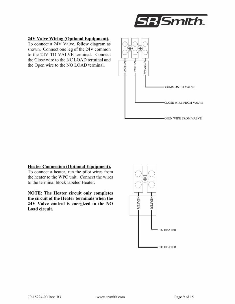
24V Valve Wiring (Optional Equipment).To connect a 24V Valve, follow diagram asshown. Connect one leg of the 24V commonto the 24V TO VALVE terminal. Connectthe Close wire to the NC LOAD terminal andthe Open wire to the NO LOAD terminal.
COMMON TO VALVE
CLOSE WIRE FROM VALVE
OPEN WIRE FROM VALVE
Heater Connection (Optional Equipment).To connect a heater, run the pilot wires fromthe heater to the WPC unit. Connect the wiresto the terminal block labeled Heater. NOTE: The Heater circuit only completesthe circuit of the Heater terminals when the24V Valve control is energized to the NOLoad circuit.
TO HEATER
TO HEATER
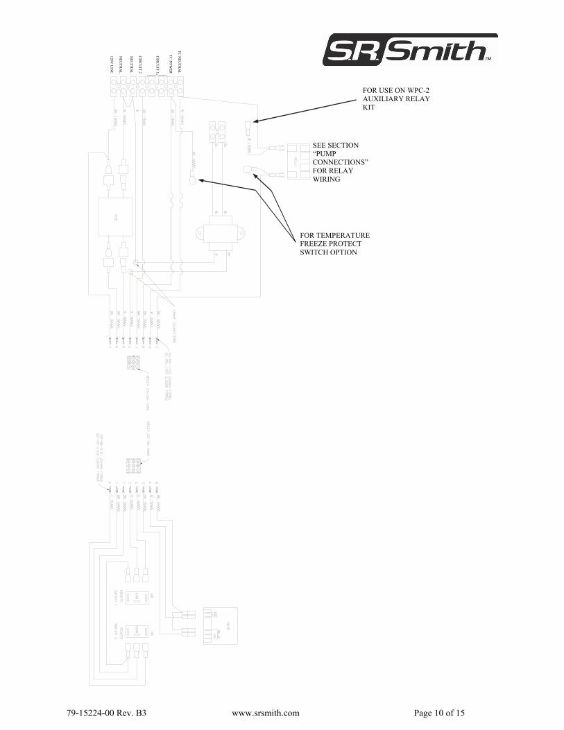
79-15224-00 Rev. B3 www.srsmith.com Page 10 of 15
FOR USE ON WPC-2 AUXILIARY RELAY KIT
SEE SECTION “PUMP CONNECTIONS” FOR RELAY WIRING
FOR TEMPERATURE FREEZE PROTECT SWITCH OPTION
TC
NE
UT
RA
L
TC
PO
WE
R
CIR
CU
IT 1
CIR
CU
IT 2
NE
UT
RA
L
NE
UT
RA
L
120V L
INE
79-15224-00 Rev. B3 www.srsmith.com Page 11 of 15
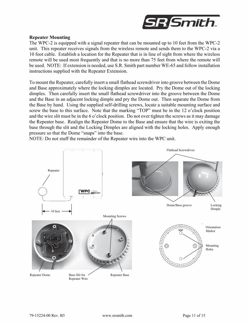
Repeater Mounting The WPC-2 is equipped with a signal repeater that can be mounted up to 10 feet from the WPC-2unit. This repeater receives signals from the wireless remote and sends them to the WPC-2 via a10 foot cable. Establish a location for the Repeater that is in line of sight from where the wirelessremote will be used most frequently and that is no more than 75 feet from where the remote will be used. NOTE: If extension is needed, use S.R. Smith part number WE-65 and follow installation instructions supplied with the Repeater Extension. To mount the Repeater, carefully insert a small flathead screwdriver into groove between the Dome and Base approximately where the locking dimples are located. Pry the Dome out of the lockingdimples. Then carefully insert the small flathead screwdriver into the groove between the Domeand the Base in an adjacent locking dimple and pry the Dome out. Then separate the Dome fromthe Base by hand. Using the supplied self-drilling screws, locate a suitable mounting surface and screw the base to this surface. Note that the marking “TOP” must be in the 12 o’clock positionand the wire slit must be in the 6 o’clock position. Do not over tighten the screws as it may damagethe Repeater base. Realign the Repeater Dome to the Base and ensure that the wire is exiting thebase through the slit and the Locking Dimples are aligned with the locking holes. Apply enough pressure so that the Dome “snaps” into the base. NOTE: Do not stuff the remainder of the Repeater wire into the WPC unit.
Flathead Screwdriver
Dome/Base groove Locking Dimple
Mounting Screws
Repeater Base Repeater Dome Base Slit for Repeater Wire
Mounting Holes
Orientation Marker
10 feet
Repeater
79-15224-00 Rev. B3 www.srsmith.com Page 12 of 15
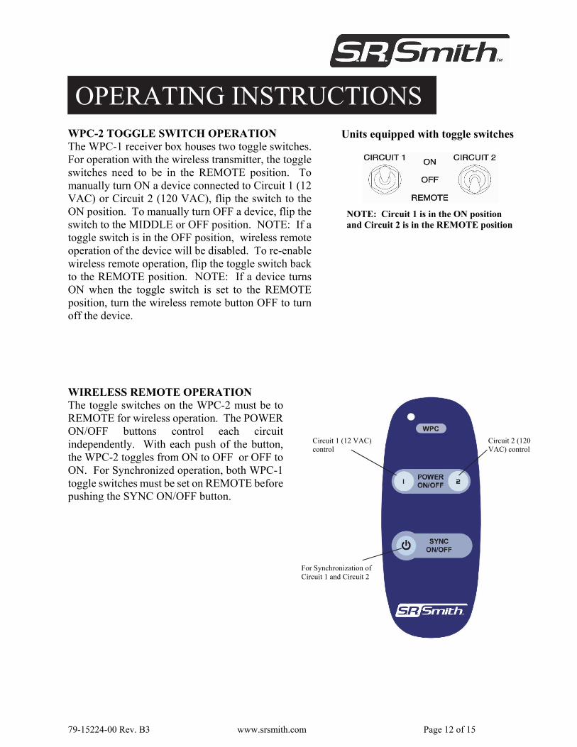
WIRELESS REMOTE OPERATION The toggle switches on the WPC-2 must be to REMOTE for wireless operation. The POWERON/OFF buttons control each circuitindependently. With each push of the button,the WPC-2 toggles from ON to OFF or OFF to ON. For Synchronized operation, both WPC-1 toggle switches must be set on REMOTE beforepushing the SYNC ON/OFF button.
Circuit 1 (12 VAC) control
Circuit 2 (120 VAC) control
For Synchronization of Circuit 1 and Circuit 2
OPERATING INSTRUCTIONS WPC-2 TOGGLE SWITCH OPERATION The WPC-1 receiver box houses two toggle switches. For operation with the wireless transmitter, the toggle switches need to be in the REMOTE position. Tomanually turn ON a device connected to Circuit 1 (12 VAC) or Circuit 2 (120 VAC), flip the switch to theON position. To manually turn OFF a device, flip the switch to the MIDDLE or OFF position. NOTE: If a toggle switch is in the OFF position, wireless remoteoperation of the device will be disabled. To re-enable wireless remote operation, flip the toggle switch back to the REMOTE position. NOTE: If a device turns ON when the toggle switch is set to the REMOTE position, turn the wireless remote button OFF to turn off the device.
NOTE: Circuit 1 is in the ON position and Circuit 2 is in the REMOTE position
Units equipped with toggle switches
79-15224-00 Rev. B3 www.srsmith.com Page 13 of 15
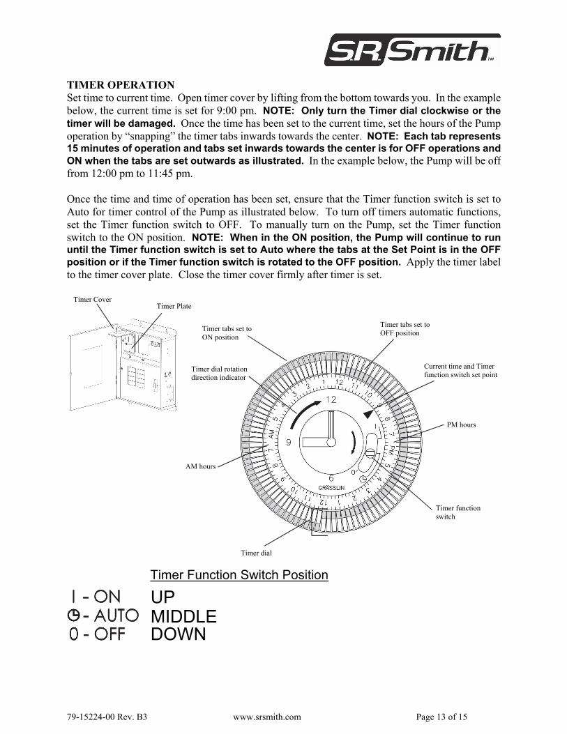
Timer Cover Timer Plate
TIMER OPERATION Set time to current time. Open timer cover by lifting from the bottom towards you. In the examplebelow, the current time is set for 9:00 pm. NOTE: Only turn the Timer dial clockwise or thetimer will be damaged. Once the time has been set to the current time, set the hours of the Pumpoperation by “snapping” the timer tabs inwards towards the center. NOTE: Each tab represents 15 minutes of operation and tabs set inwards towards the center is for OFF operations and ON when the tabs are set outwards as illustrated. In the example below, the Pump will be off from 12:00 pm to 11:45 pm. Once the time and time of operation has been set, ensure that the Timer function switch is set toAuto for timer control of the Pump as illustrated below. To turn off timers automatic functions,set the Timer function switch to OFF. To manually turn on the Pump, set the Timer functionswitch to the ON position. NOTE: When in the ON position, the Pump will continue to rununtil the Timer function switch is set to Auto where the tabs at the Set Point is in the OFFposition or if the Timer function switch is rotated to the OFF position. Apply the timer label to the timer cover plate. Close the timer cover firmly after timer is set.
Timer dial rotation direction indicator
Timer tabs set to ON position
Timer tabs set to OFF position
Current time and Timer function switch set point
Timer dial
Timer function switch
PM hours
AM hours
UP MIDDLE DOWN
Timer Function Switch Position
79-15224-00 Rev. B3 www.srsmith.com Page 14 of 15
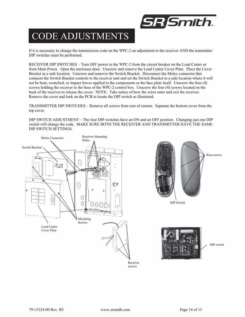
CODE ADJUSTMENTS
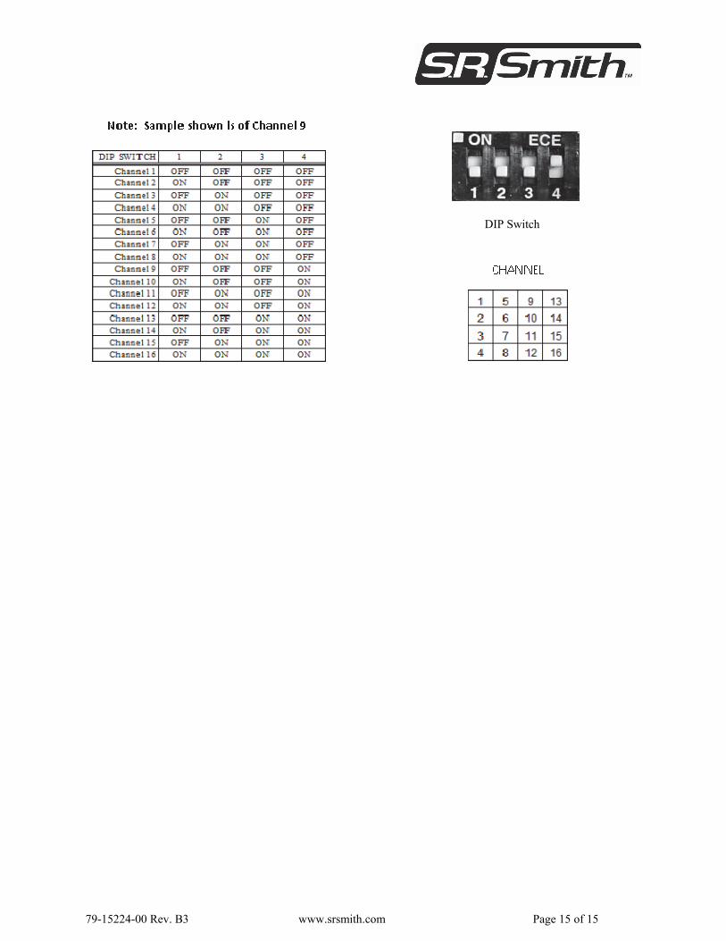
If it is necessary to change the transmission code on the WPC-2 an adjustment to the receiver AND the transmitter DIP switches must be performed. RECEIVER DIP SWITCHES – Turn OFF power to the WPC-2 from the circuit breaker on the Load Center or from Main Power. Open the enclosure door. Unscrew and remove the Load Center Cover Plate. Place the Cover Bracket in a safe location. Unscrew and remover the Switch Bracket. Disconnect the Molex connector that connects the Switch Bracket controls to the receiver unit and set the Switch Bracket in a safe location where it will not be bent, scratched, or impact forces applied to the components or the face plate itself. Unscrew the four (4) screws holding the receiver to the base of the WPC-2 control box. Unscrew the four (4) screws located on the back of the receiver to release the cover. NOTE: Take notice of how the wires enter and exit the receiver. Remove the cover and look on the PCB to locate the DIP switch as illustrated. TRANSMITTER DIP SWITCHES – Remove all screws from rear of remote. Separate the bottom cover from the top cover. DIP SWITCH ADJUSTMENT – The four DIP switches have an ON and an OFF position. Changing just one DIP switch will change the code. MAKE SURE BOTH THE RECEIVER AND TRANSMITTER HAVE THE SAME DIP SWITCH SETTINGS.
Receiver screws
DIP switch
DIP Switch
Rear screws
Load Center Cover Plate
Molex Connector
Mounting Screws
Receiver Mounting Holes
Switch Bracket
79-15224-00 Rev. B3 www.srsmith.com Page 15 of 15
DIP Switch