Embed Size (px)
Citation preview

Tidal Energy Systems: Design Guidance on
Grid Connection Configuration and
Infrastructure for Multiple Device Types
VERSION: 1.0 DATE: SEPTEMBER 2015
Author Ben Whitby (IT Power)

2
This project has been co-funded by ERDF under the INTERREG IVB NWE programme. The report reflects the author’s views and the Programme Authorities are not liable for any use that may be made of the information contained therein.
Technical Report: Tidal Energy Systems: Design guidance on grid
connection configuration and infrastructure for multiple device types
September 2015
Contractor: IT Power
IT Power
St. Brandon’s House
29 Great George Street
Bristol, BS1 5QT, UK
Tel: +44 117 214 0510
Fax: +44 117 214 0511
E-mail: [email protected]
Website: www.itpower.co.uk
Document control
File path & name I:\Data\0WorkITP\0Projects\1191 PTEC Phase 1
Delivery FEED & EIA\2 Work
Author B. Whitby (IT Power)
Project Manager J. Hussey (IT Power)
Approved J. Hussey (IT Power)
Date September 2015
Distribution level -

3
CONTENTS
Chapter 1 Introduction ............................................................................................ 4
Chapter 2 Grid Connecting Tidal Turbines .................................................................. 5
Electrical drivetrain options ................................................................................... 5
Asynchronous (Induction) Generator ................................................................... 6
Doubly-Fed Induction Generator ......................................................................... 7
Generator with full power converter interface ....................................................... 8
Voltage levels .................................................................................................... 10
Chapter 3 Design of the Electrical netwrok architecture ............................................. 13
Radial String Connection ..................................................................................... 13
Offshore hubs and platforms ............................................................................... 16
Topologies for Larger Arrays ................................................................................ 20
DC transmission connection ................................................................................ 22
Chapter 4 Conclusions ........................................................................................... 27
Chapter 5 References ............................................................................................ 28

4
CHAPTER 1 INTRODUCTION
The tidal energy industry has seen little convergence on a particular electrical design and
developers use a variety of different design philosophies. This report provides guidance on
the design options for the electrical infrastructure required to connect arrays of tidal
energy devices to the grid. The report initially looks at the electrical options at the turbine
level in Section Error! Reference source not found., which includes the drive train and
power take-off options. The electrical architecture options for grid connecting the array
system, including inter-array and transmission connection options, is discussed in Section
Error! Reference source not found.. The feasibility of designing an electrical
infrastructure flexible enough to accommodate multiple device types with non-
standardised electrical outputs is also investigated.

5
CHAPTER 2 GRID CONNECTING TIDAL TURBINES
There are a number of different options to consider when connecting an array of tidal
turbines to the grid. This section covers the electrical drivetrain selection considerations
and the voltage selection at the turbine level. The options discussed within this section
are:
Electrical drivetrain options for the generator and convertor package distinguished
by rotational speed, power regulation and type of generator. The type of generators
available (synchronous or asynchronous) are discussed.
Voltage selection including generator voltage and transmission voltage, identifying
the options available for the location (i.e. onshore or offshore) and type of electrical
infrastructure (transformers, converters/rectifiers, power conditioning equipment
etc.).
ELECTRICAL DRIVETRAIN OPTIONS The electrical drivetrain – generator converter package - is an integral part of any tidal
turbine and is responsible for converting the kinetic energy into electric power for transfer
into the grid. The types of generator used by tidal turbine developers can be divided into
two groups:
Synchronous generators, where the rotor and magnetic field rotate with the same
speed, and are either permanently or separately excited.
Asynchronous (induction) generators which are either singly or doubly-fed.
These generators can be used in a number of configurations. Induction generators directly
coupled to the grid offer a simple low cost solution but have a number of disadvantages
and are unlikely to be widely adopted by developers. The remaining configurations, which
could be used by developers, can be summarised as follows.
Doubly-fed induction generators using partially rated converters.
Synchronous generators (either permanently or separately excited) use full power
converter interfaces.
These configurations are discussed in more detail in the section that follows.

6
ASYNCHRONOUS (INDUCTION) GENERATOR
The use of induction generators (either singly or doubly-fed) in conjunction with a
gearbox is commonly proposed. The squirrel cage induction generator (SCIG) is popular
due to its cheap and robust design; nothing more than an induction motor driven above
its synchronous speed. In its simplest configuration, the stator windings are directly
connected to the grid, and a high speed low torque SCIG with a gearbox inserted between
the shaft of the turbine rotor and the shaft of the generator is used (Error! Reference
source not found.). This configuration is considered to be fixed speed; although, the
speed will vary slightly (due to the slip) as the operating power of the rotor fluctuates [1].
The gearbox is necessary to convert the low rotational speed of the turbine rotor to a
compatible frequency of the available network, which would be 1500 rotations per minute
(RPM) for a four pole machine connected to the European 50Hz network. The turbine and
gearbox ratio has to match the available generator speeds, which are for standard
induction generators 1500RPM, 1000RPM and 750RPM (4, 6 or 8 pole) [2].
An uncompensated Induction generator at rated output will normally have a power factor
in the region of 0.89 leading (i.e. consuming reactive power). For a 1 MW turbine this
implies a reactive power draw of 512Kvar. However, typically in such a system the
reactive power is compensated using shunt capacitor banks, as shown in Error!
Reference source not found., so that the power factor is closer to 1. Typically, a
compensated system will operate at 0.98 leading which implies a reactive power draw of
85Kvar.
Figure 2.1: Squirrel cage induction genrator in fixed speed configuration

7
The disadvantage of this configuration is the fixed speed operation; which results in less
than optimal power production because the rotor speed cannot be adapted to the flow
speed (see Error! Reference source not found.). The fact that the generator is directly
coupled to the grid also means that any fluctuations in rotor torque are translated directly
into output power variations which adversely affects the power quality. Furthermore, one
has no control over the reactive power flow with this topology. The lack of control makes
it difficult to comply with relevant grid codes.
Figure 2.2: Turbine power curves comparing fixed speed(black line) and variable speed
(grey line) generators
DOUBLY-FED INDUCTION GENERATOR
An improvement on this configuration, which allows a degree of variable speed operation
to be achieved, is to use a wound rotor induction generator in conjunction with a partially
rated power converter (Error! Reference source not found.). This is known as a
doubly-fed induction generator (DFIG) and is widely used in the wind industry. During
under-speed (sub-synchronous operation) the converter will borrow power from the
line, which it passes on to the stator. When the rotor over-speeds (super-synchronous
operation) the converter absorbs power from the rotor and feeds it to the power line.
In this way the rotor speed can be varied to optimise the hydrodynamic efficiency. With
this configuration it is also possible to independently control the flow of active and

8
reactive power which makes the system more flexible and able to comply with relevant
grid codes.
The power flowing through the converter is proportional to the speed variation e.g. for
a +/-30% speed variation, the rated power of the converter is only about 30% of the
rated power of the generator [3]). Therefore, the converter is cheaper and causes less
loss than systems employing fully rated power converters. However, the generator is
more expensive and maintenance requirements are high due to the use of slip rings. For
these reasons, although it has been widely adopted in the wind industry, tidal
developers are unlikely to adopt the DFIG. The increased complexity of the generator
and control, as well as the need to use a multistage gearbox means that it is unlikely
to be considered robust enough for use in a marine environment.
Figure 2.3: Doubly-Fed induction generator configuration
GENERATOR WITH FULL POWER CONVERTER INTERFACE
The alternative is to use a full-power converter in conjunction with either an induction
generator or a synchronous generator. This configuration allows for full variable speed
operation and one has full independent control of the active and reactive power flow.
9
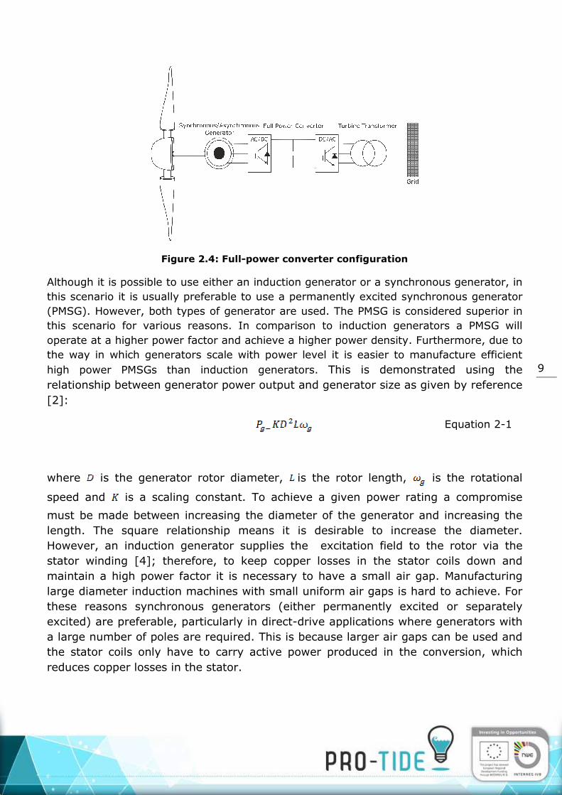
Figure 2.4: Full-power converter configuration
Although it is possible to use either an induction generator or a synchronous generator, in
this scenario it is usually preferable to use a permanently excited synchronous generator
(PMSG). However, both types of generator are used. The PMSG is considered superior in
this scenario for various reasons. In comparison to induction generators a PMSG will
operate at a higher power factor and achieve a higher power density. Furthermore, due to
the way in which generators scale with power level it is easier to manufacture efficient
high power PMSGs than induction generators. This is demonstrated using the
relationship between generator power output and generator size as given by reference
[2]:
Equation 2-1
where is the generator rotor diameter, is the rotor length, is the rotational
speed and is a scaling constant. To achieve a given power rating a compromise
must be made between increasing the diameter of the generator and increasing the
length. The square relationship means it is desirable to increase the diameter.
However, an induction generator supplies the excitation field to the rotor via the
stator winding [4]; therefore, to keep copper losses in the stator coils down and
maintain a high power factor it is necessary to have a small air gap. Manufacturing
large diameter induction machines with small uniform air gaps is hard to achieve. For
these reasons synchronous generators (either permanently excited or separately
excited) are preferable, particularly in direct-drive applications where generators with
a large number of poles are required. This is because larger air gaps can be used and
the stator coils only have to carry active power produced in the conversion, which
reduces copper losses in the stator.

10
Separately excited synchronous generators can also be used. The main advantage of
this configuration over the permanently excited machine is that one has the ability to
control the excitation current and therefore the no load voltage can be controlled. The
disadvantage is the high complexity of this type of machine for excitation and voltage
control and the use of brushes and slip rings which will increase cost and
maintenance. In the wind industry these were initially favoured over PMSGs due to
the high cost and limited availability of the materials needed for permanent magnets;
however, availability is no longer a significant issue and prices have dropped over the
last ten years.
Based on this review, it can be argued that the most attractive solution for tidal
turbine developers is the PMSG with full-power converter interface. However, it is
acknowledged that some developers may also choose to use an induction generator in
combination with a full-power converter. Fixed speed induction generators and DFIG
configurations are highly unlikely to be used in large numbers by tidal developers;
therefore, for the purposes of this report these topologies will not be considered when
designing the electrical network.
VOLTAGE LEVELS
Another differentiator between tidal devices is the voltage level at which the devices
operate. In the wind industry low voltage generators ranging from 690V to 1000V are
very common. This voltage is usually stepped–up using a transformer located in the
base of the turbine tower. More recently medium voltage generators, ranging between
3kV and 6.6kV, are starting to be used on larger multi-megawatt wind turbines. This
is because the higher voltages lead to lower currents, reducing resistive losses and
enabling the use of smaller diameter cables within the turbine [5].
In the tidal sector there has been little convergence and device developers are
generating at a range of voltages from 0.4kV to 6.6kV. This is further complicated by
the fact that some developers have on-board transformers which step up the voltage
whereas others simply transmit to shore at a variable AC voltage direct from the
generator. Others have proposed using a DC transmission option. Developers such as
Tidal Generation Ltd [6] and Marine Current Turbines [7] have on-board transformers
which step up the voltage from the low voltage generators to 6.6kV and 11kV
respectively. Both these devices also have on-board power converters. Therefore,
these devices are configured exactly as shown in Error! Reference source not
found. and are very similar to modern wind turbines. Both these companies also
state that they would be capable of generating higher voltages such as 33kV,

11
presumably by simply changing the transformer or altering the tapping ratio. The
developer Tidal Energy Ltd [8] is believed to be using a medium voltage 6.6kV
generator; however, there is not believed to be a transformer or additional conversion
equipment on board. The turbine simply transmits variable AC to shore at which point
it connects to a power converter and transformer as shown in Error! Reference
source not found..
Figure 2.5: Turbine with medium voltage generator and all power conversion equipemnt
onshore
Another option is to split the power converter so that the rectifier is located offshore,
either on-board the turbine or in a separate hub, and the inverter is located in an onshore
converter station. The power is transmitted to the shore-side converter via a medium
voltage DC link as shown in Error! Reference source not found.. The necessary DC
voltage level will be determined by the length of the link and will also depend on the AC
voltage from the generator [9].

12
Figure 2.6: Split Converter topology using DC transmission link
The range of configurations being adopted by device developers makes it difficult to
design a standardised electrical infrastructure able to cater to all current device types.
However, this report will aim to propose systems flexible enough to accommodate the
range of configurations detailed in Error! Reference source not found., Error!
Reference source not found. and Error! Reference source not found..

13
CHAPTER 3 DESIGN OF THE ELECTRICAL NETWROK ARCHITECTURE There are a number of options when considering connecting an array of multiple tidal
turbines to the grid. Within this chapter the following design options are reviewed:
Individual radial strings to shore for devices operating at the same voltage or
different voltage levels.
Offshore collection hubs for the use of grid connecting tidal turbine arrays consisting of devices operating at the same or different voltage levels. The options
for onshore and offshore transformers are discussed for the hub layout.
The considerations for hub connections with dry mate or wet mate connectors.
Subsea hubs versus surface-piercing offshore platforms.
Options for larger turbine arrays considering a multiple hub layout.
DC transmission connections (split converter topology).
RADIAL STRING CONNECTION
For full-power converter devices, like that shown in Error! Reference source not
found., the connection can be done in a very similar way to a conventional offshore wind
farm; whereby, individual devices are connected in radial strings as shown in Error!
Reference source not found.. Switchgear devices enable individual turbines to be
isolated.

14

15
Figure 3.1: Turbines connected in radial strings with individual AC cables to shore: (a)
onshore substation contains a couple of two-winding transformers to accommodate
multiple voltage levels, (b) three winding transformer is used in the onshore substation
to accommodate multiple voltage levels.
In Error! Reference source not found., a scenario where two voltage levels are used is
shown. In this scenario separate two winding transformers can be used as shown in
Error! Reference source not found.(a) or alternatively a single three winding
transformer can be used as shown in Error! Reference source not found.(b). The
advantage of the latter option is that a three winding transformer will have a smaller
footprint than two separate transformers. It also means that only one set of switchgear
needs to be used on the high voltage side. The disadvantage of the three winding
transformer are the higher power losses which is significant when one considers that the
lifetime of the plant could be between 20-30 years. The three winding transformer is also
heavier, as a single component, than separate two winding transformers which may have
implications on the installation.
This is a flexible solution as it allows multiple device types operating at different voltage
levels to be used. In theory each radial string could be operated at a separate voltage
level. The use of multiple cables to shore also provides a high level of redundancy. This
system could be used with devices that do not have an on-board transformer. However,
for devices using low voltage (<1kV) generators the transmission distance to shore would
be limited. Devices using medium voltage generators (3kV-6.6kV) would be able to

16
achieve longer transmission distances. The voltage level of each string will also affect the
number of devices that can be connected in a given string. Higher voltages will reduce
current flow in the radial cable and increase the number of devices that can be connected.
The high number of cables is a disadvantage of this system. Furthermore, in order to
accommodate multiple voltage levels the onshore substation needs to be equipped with
multiple transformers and switchgear devices to accommodate each voltage level. This
will increase the cost and footprint of the substation.
Another issue with the radial string design is how to loop the cable in and out of each
turbine in order to create the string. This could be achieved using a double set of
connectors but this will add cost. Furthermore most tidal developers seem to have
designed their devices to accommodate just one cable connection due to space
constraints. A solution could be to use a three-way (or T-connector). However, the
commercial availability of such connectors is not known and this is an area that may
require development before such systems can be realised in reality.
Figure 3.2: Four turbine radial string with three-way connectors
OFFSHORE HUBS AND PLATFORMS
The electrical topologies proposed above are based on the use of radial array networks.
Other solutions which fall into the category of hubs utilising star cluster type network
configurations offer an alternative solution. Offshore collection hubs are useful for
reducing the number of cable runs to shore. As illustrated in Error! Reference source
not found., to accommodate multiple voltage levels, multiple cable runs to shore would
still be required; however, if several radial strings operate at the same voltage level then
the number of cables to shore will be reduced.
17
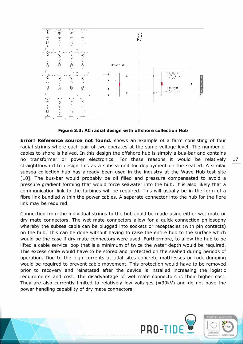
Figure 3.3: AC radial design with offshore collection Hub
Error! Reference source not found. shows an example of a farm consisting of four
radial strings where each pair of two operates at the same voltage level. The number of
cables to shore is halved. In this design the offshore hub is simply a bus-bar and contains
no transformer or power electronics. For these reasons it would be relatively
straightforward to design this as a subsea unit for deployment on the seabed. A similar
subsea collection hub has already been used in the industry at the Wave Hub test site
[10]. The bus-bar would probably be oil filled and pressure compensated to avoid a
pressure gradient forming that would force seawater into the hub. It is also likely that a
communication link to the turbines will be required. This will usually be in the form of a
fibre link bundled within the power cables. A separate connector into the hub for the fibre
link may be required.
Connection from the individual strings to the hub could be made using either wet mate or
dry mate connectors. The wet mate connectors allow for a quick connection philosophy
whereby the subsea cable can be plugged into sockets or receptacles (with pin contacts)
on the hub. This can be done without having to raise the entire hub to the surface which
would be the case if dry mate connectors were used. Furthermore, to allow the hub to be
lifted a cable service loop that is a minimum of twice the water depth would be required.
This excess cable would have to be stored and protected on the seabed during periods of
operation. Due to the high currents at tidal sites concrete mattresses or rock dumping
would be required to prevent cable movement. This protection would have to be removed
prior to recovery and reinstated after the device is installed increasing the logistic
requirements and cost. The disadvantage of wet mate connectors is their higher cost.
They are also currently limited to relatively low voltages (≈30kV) and do not have the
power handling capability of dry mate connectors.

18
The design shown in Error! Reference source not found. could be altered by moving
the transformers offshore as shown in Error! Reference source not found.. This
reduces the number of cable runs to shore. The decision to move the transformers
offshore would primarily depend on the power rating of the array and the distance to the
onshore point of common coupling. Increasing the transmission voltage to shore will
reduce the resistive losses in the cable which will, to a certain extent, offset the extra cost
of placing transformers offshore. However, at very long distances (>50km [11]) reactive
power losses will dominate and the cable will need to be compensated. Compensation can
be done only on the onshore side, but is most effective when done at both ends of the
cable [12]. In this design the offshore hub would contain the following components:
Step-up transformers
Circuit breakers
Offline switches to isolate incoming lines on each bus bar
Wet mate connectors for connection of turbines
Reactive compensation equipment (dependent on cable length and voltage level)
Figure 3.4: AC radial design with offshore substation
19
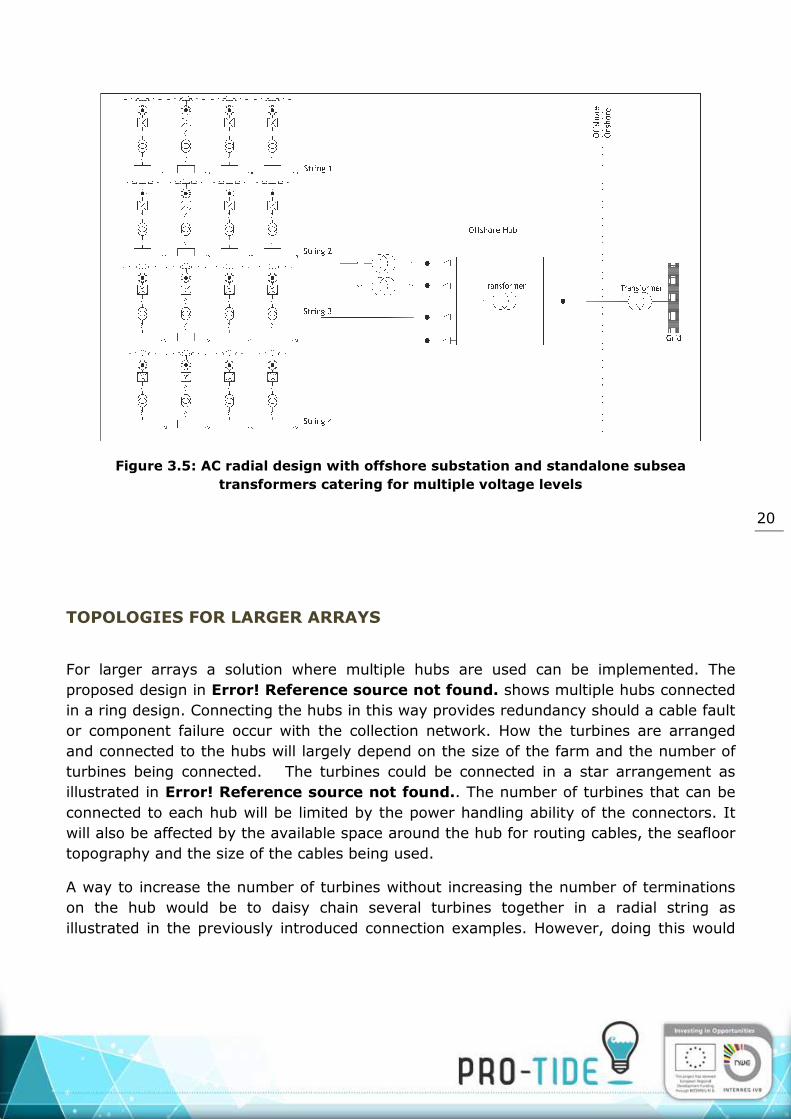
In Error! Reference source not found. the hub contains multiple transformers. This is
to accommodate multiple voltage levels within the array. As explained previously the use
of two separate transformers could be replaced by a single three winding transformer. In
either case the size and mass of the equipment may mean that it cannot sensibly be
housed in a single subsea hub. It may be sensible to adopt the approach shown in Error!
Reference source not found. whereby external subsea transformers are used to step
up the voltage from certain strings before connection to the main hub. Error! Reference
source not found. shows an example where strings 1 and 2 operate at a lower voltage
than strings 3 and 4. Subsea transformers designed as standalone systems are now
available from a number of vendors ( [13], [14]), having been primarily developed for the
oil and gas market. These transformers can be fully submerged at depth and do not need
to be housed in a barometric chamber.
An alternative to the subsea approaches would be to use a fixed platform. Platforms are
better suited to coping with complex cable landings (making it easier to incorporate large
numbers of turbines), and with large volumes of equipment weighing significant amounts.
Platforms would also provide for more space and additional services. For prototype
farms, using new power collection concepts, deploying equipment above the surface
would provide easier access for maintenance and monitoring. Furthermore, electrical
equipment for use on platforms is more widely available and has been tried and tested.
Once the power system has been proven and understood, the riskier step of repackaging
into a subsea module could potentially be undertaken.
The disadvantage of platforms is the increased visual and environmental impact that they
may have. Particularly as most early tidal array developments are likely to be relatively
close to shore at distances between 5 and 20km. The cost of the platform will be a big
factor and is one that is hard to quantify as it will be influenced by the strength of the
tidal flow and the specific conditions at each site. A platform is likely to become an option
for larger farms (>50MW) further from shore where the size of the equipment and the
number of cables make it a more viable solution. However, as stated already, they may
also be viable in smaller prototype farms where proof of concept and reliability are
considered more important than other factors.
20
Figure 3.5: AC radial design with offshore substation and standalone subsea
transformers catering for multiple voltage levels
TOPOLOGIES FOR LARGER ARRAYS
For larger arrays a solution where multiple hubs are used can be implemented. The
proposed design in Error! Reference source not found. shows multiple hubs connected
in a ring design. Connecting the hubs in this way provides redundancy should a cable fault
or component failure occur with the collection network. How the turbines are arranged
and connected to the hubs will largely depend on the size of the farm and the number of
turbines being connected. The turbines could be connected in a star arrangement as
illustrated in Error! Reference source not found.. The number of turbines that can be
connected to each hub will be limited by the power handling ability of the connectors. It
will also be affected by the available space around the hub for routing cables, the seafloor
topography and the size of the cables being used.
A way to increase the number of turbines without increasing the number of terminations
on the hub would be to daisy chain several turbines together in a radial string as
illustrated in the previously introduced connection examples. However, doing this would

21
increase the size of the cables needed and one would still ultimately be limited by the
power handling capabilities of the connectors going into the hub.
Figure 3.6: Multi-hub collection network

22
Figure 3.7: Turbines connected to hub in a star configuration
DC TRANSMISSION CONNECTION
This type of connection was introduced in Error! Reference source not found. and is
often referred to as the split converter topology. The rectifier is located offshore either on
board the turbine or in a separate hub, and the inverter is onshore. This topology
minimises the amount of equipment located offshore; however, the transmission distance
is limited by the current carrying ability of the DC cable which in turn is affected by the
chosen voltage level. Selecting a high DC voltage level will reduce the current flow but will
increase the size and cost of the converters. The minimum DC voltage depends on the AC
input voltage from the turbines given by [15]:
Equation 3-1
is the DC link voltage, is the line to line AC input voltage and is the modulation
ratio of the converter.
The design of the inter-array network can be done in a similar way to the AC designs
already discussed where individual devices are connected in radial strings or in a star
configuration. Error! Reference source not found. shows a scenario where multiple
devices are connected in parallel to a hub in a star configuration.

23
Figure 3.8: Split converter topology with turbines connected in star configuration using
DC transmission link to shore
This system could be expanded to accommodate larger farms in a ring topology as shown
in Error! Reference source not found.. DC switchgear devices would be required to
maintain the integrity of the ring.

24
Figure 3.9:DC RING SYSTEM
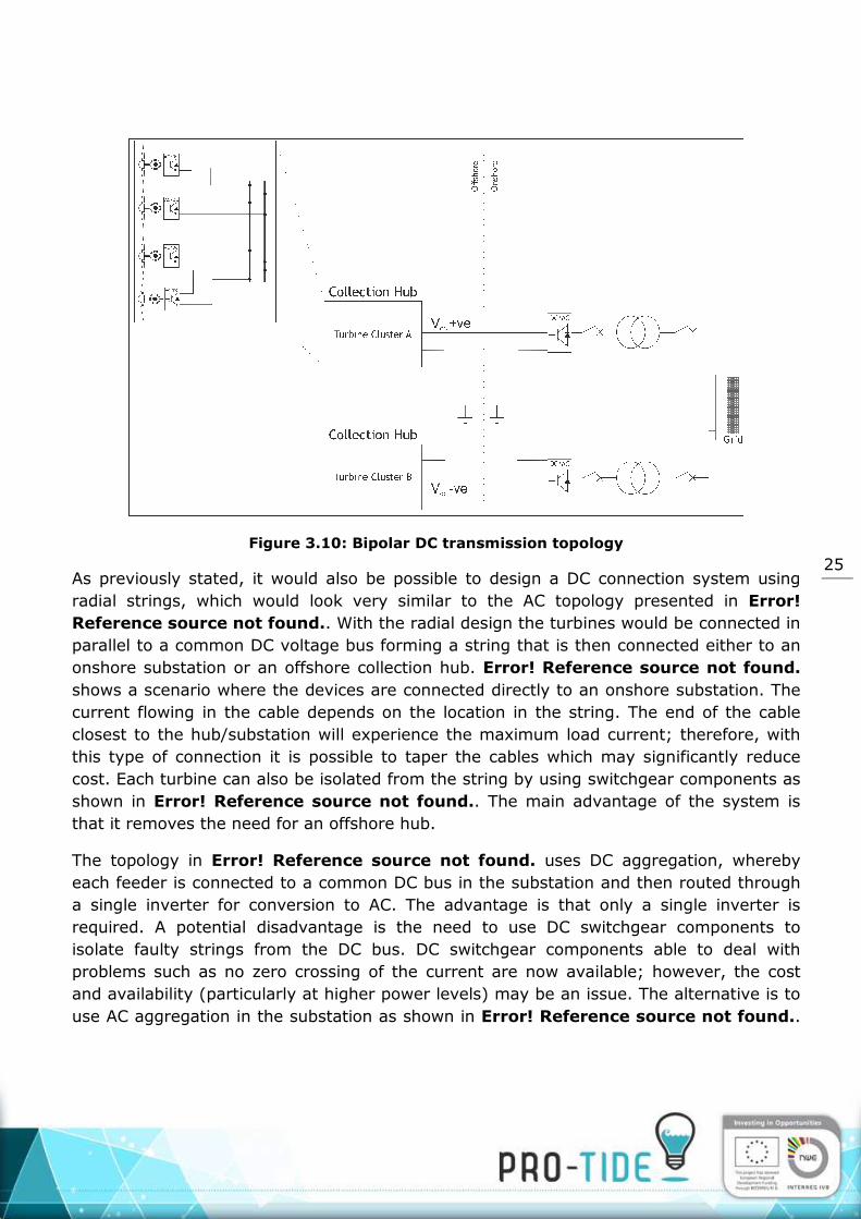
An alternative to the system of Error! Reference source not found., which could also
accommodate larger farms, is shown in Error! Reference source not found.. In this
system two collection hubs are combined to form a bipolar DC transmission system. One
of the collection hubs produces negative valued DC output while the other produces
positive valued DC output. This leads to a bipolar DC transmission system where one pole
is positive with respect to earth and the other is negative. Under normal operation
current will flow in a loop and there will be no current flow through the ground return.
Crucially each pole is able to function independently as a monopolar link, by using the
earth as a return path. If the return path is designed with suitable capacity to carry the
load of both poles then power transmission can continue should one of the poles be out of
service due to a fault or maintenance work. This provides useful redundancy and is the
main advantage of this topology.
25
Figure 3.10: Bipolar DC transmission topology
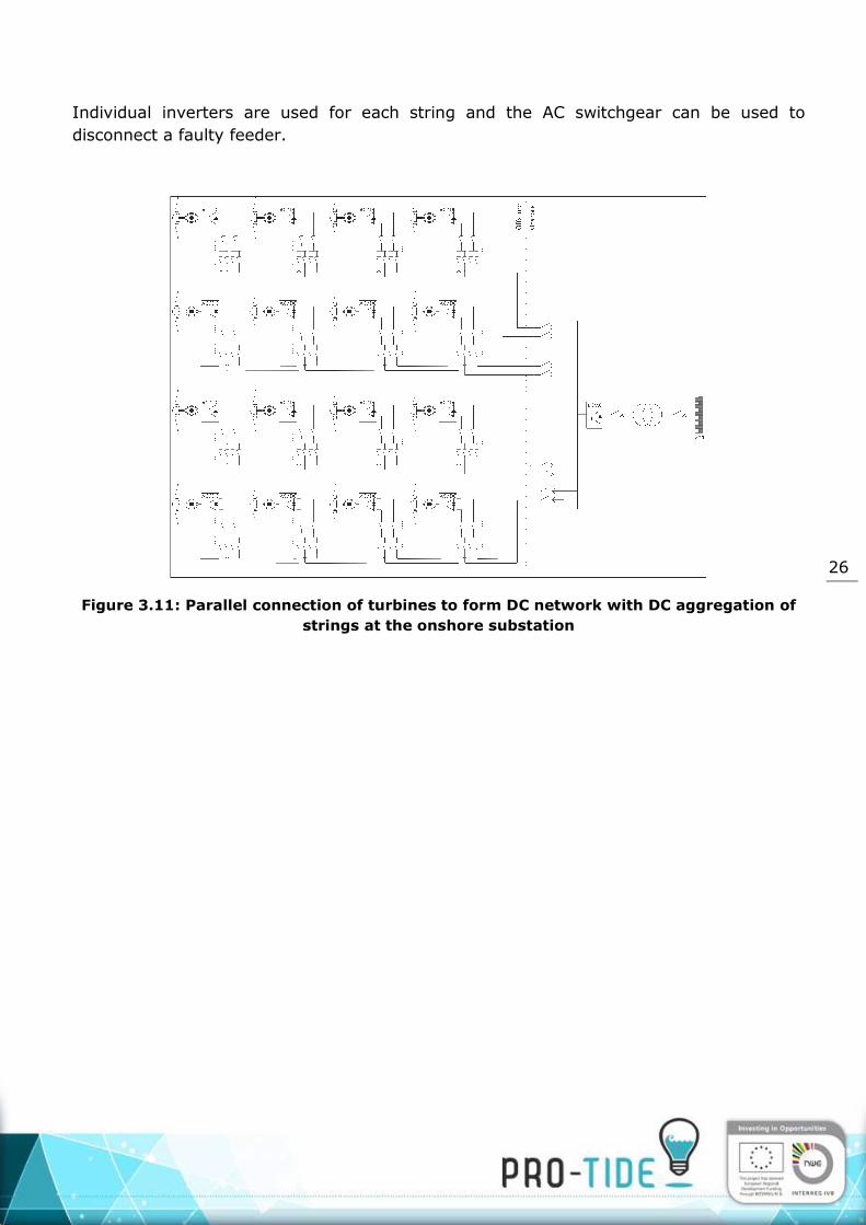
As previously stated, it would also be possible to design a DC connection system using
radial strings, which would look very similar to the AC topology presented in Error!
Reference source not found.. With the radial design the turbines would be connected in
parallel to a common DC voltage bus forming a string that is then connected either to an
onshore substation or an offshore collection hub. Error! Reference source not found.
shows a scenario where the devices are connected directly to an onshore substation. The
current flowing in the cable depends on the location in the string. The end of the cable
closest to the hub/substation will experience the maximum load current; therefore, with
this type of connection it is possible to taper the cables which may significantly reduce
cost. Each turbine can also be isolated from the string by using switchgear components as
shown in Error! Reference source not found.. The main advantage of the system is
that it removes the need for an offshore hub.
The topology in Error! Reference source not found. uses DC aggregation, whereby
each feeder is connected to a common DC bus in the substation and then routed through
a single inverter for conversion to AC. The advantage is that only a single inverter is
required. A potential disadvantage is the need to use DC switchgear components to
isolate faulty strings from the DC bus. DC switchgear components able to deal with
problems such as no zero crossing of the current are now available; however, the cost
and availability (particularly at higher power levels) may be an issue. The alternative is to
use AC aggregation in the substation as shown in Error! Reference source not found..
26
Individual inverters are used for each string and the AC switchgear can be used to
disconnect a faulty feeder.
Figure 3.11: Parallel connection of turbines to form DC network with DC aggregation of
strings at the onshore substation

27
Figure 3.12: Parallel connection of wind turbines to form DC network with AC
aggregation of strings at the offshore substation
CHAPTER 4 CONCLUSIONS
It is difficult to recommend a particular electrical network from those introduced as the
most suitable network will very much depend on influencing factors; particularly, the type
of devices used, size of the array and distance from shore. Accommodating wide variance
in machine types and voltage levels is impossible to do while still maintaining a
standardised electrical collection network. However, different voltage levels can be
accommodated albeit at an extra cost.
The radial network configurations introduced in Error! Reference source not found. will
likely be the lowest cost options and offer flexibility in terms of voltage levels as each
string can be operated at a different voltage level. The use of subsea hubs has drawbacks
and presents a number of challenges. There are practical difficulties with connecting
multiple cables to a submarine hub. The operation requires the use of expensive mate-
able connectors and potentially the use of ROVs and divers. There are also limitations on
the number of devices that can practically be connected to a hub. Finally, the construction
and installation costs of submarine hubs is likely to be high and there is little experience
in this area apart from that gained by the oil and gas industry. Despite this hubs will still
be a viable solution in situations where arrays are deployed far from shore and stepping
up the transmission voltage offshore is necessary. It can also be justified in situations
where a large number of devices are deployed and the use of a hub will significantly

28
reduce the number of export cables to shore, such as in the topology shown in Error!
Reference source not found.. In this scenario the cost saving by reducing the cabling
will offset the price of the hub.
The DC solution proposed has the potential to be one of the lowest cost solutions with
lower electrical losses than many of the proposed AC solutions. The DC solutions proposed
in Error! Reference source not found. and Error! Reference source not found.
minimise the offshore equipment and are particularly suitable in situations where placing
full power converters within devices or in separate offshore hubs is not feasible. A study
conducted by ABB [16] into electrical infrastructure for connecting commercial tidal
power arrays of between 30MW-200MW in size concluded that a DC collection network
was their preferred solution as it offered the lowest component count of subsea elements
and the lowest electrical losses. There is also potential to reduce the cost of DC topologies
further by allowing multiple devices to share common converters on the generator side.
There is much research being done in this area [17] [18]. However, the control aspects of
such topologies are onerous and the sharing of converters will likely result in a reduction
in energy yield from an array as individual devices will not be able to operate at optimal
efficiency.
CHAPTER 5 REFERENCES
[1] O. Anaya Lara, N. Jenkins, J. Ekanayake, P. Cartwright en M. Hughes, Wind Energy
Generator Modelling and Control, Chichester: John Wiley &Sons Ltd , 2009.
[2] T. Burton, D. Sharpe, N. Jenkins en E. Bossanyi, Wind Energy Handbook, Chichester :
John Wiley & Sons , 2001.
[3] E. Muljadi, M. Singh en V. Gevorgian, „Doubly Fed Induction Generator in an Offshore
Wind Power Plant Operated at Rated V/Hz,” in IEEE Energy Conversion Congress and
Exhibition, Raleigh, 2012.
[4] P. Pillay en K. R., „Modelling, Simulation, and Analysis of Permanent Magnet Motor
Drives, Part 1: The Permanent Magnet Synchronous Motor Drive,” IEEE Transactions
on Industry Applications, vol. 25, nr. 2, pp. 265-273, 1989.
[5] ABB , „ABB generators and converters help AREVA wind turbines optimise energy yield
at alpha ventus,” [Online]. Available:

29
https://library.e.abb.com/public/e6ede065616409e6c1257d89002a6875/Case%20not
e_alpha%20ventus_lowres.pdf. [Geopend 6th August 2015].
[6] ALSTOM, „Tidal Generation Ltd,” [Online]. Available:
http://www.alstom.com/products-services/product-catalogue/power-
generation/renewable-energy/ocean-energy/tidal-energy/tidal-power/. [Geopend 6th
August 2015].
[7] Siemens , „Marine Current Turbines,” [Online]. Available:
http://www.marineturbines.com/. [Geopend 6th August 2015].
[8] Tidal Energy Ltd., „Delta Stream Tidal Technology,” [Online]. Available:
http://www.tidalenergyltd.com/. [Geopend 6th August 2015].
[9] N. Mohan, T. Undeland en W. Robbins, Power Electronics: Converters, Applications
and Design, New Jersey: John Wiley & Sons, 2002.
[1
0]
Wave Hub Limited, „Wave Hub Test Site,” 2015, [Online]. Available:
http://www.wavehub.co.uk/. [Geopend 6 August 2015].
[1
1]
Technalia , „Integrating Wave and Tidal Current Power: Case Studies through
Modelling and Simulation,” Interanational Energy Agency, 2011.
[1
2]
M. Zubiaga, G. Abad, J. Barrena, S. Autenetxea en A. Carcar, Energy Transmission
and Grid Integration of AC Offshore Wind Farms, Croatia : InTech, 2012.
[1
3]
Siemens , „Siemens Subsea Power Grid,” [Online]. Available:
http://www.energy.siemens.com/hq/en/industries-utilities/oil-
gas/applications/subsea/systems/power/power-grid/subsea-transformers.htm.
[Geopend 9 August 2015].
[1
4]
ABB, „Subsea Transformers,” [Online]. Available:
http://new.abb.com/products/transformers/special-application/offshore-and-subsea.
[Geopend 9th August 2015].
[1
5]
GE Power Conversion, „Electrical infrastructure required for commercial scale tidal
power arrays,” SSE Renewables (UK) Limited , Rugby, 2013.
[1
6]
ABB, „Proposal for a commercial scale tidal array concept study,” Scottish and
Southern Energy , 2013.
[1 D. Elliott, S. Finney en C. Booth, „Single converter interface for a cluster of offshore

30
7] wind turbines,” in Renewable Power Generation , IET Conference on, Edinburgh, 2011.
[1
8]
D. Jovcic en N. Strachan, „Offshore wind farm with centralised power conversion and
DC interconnection,” Generation, Transmission & Distribution, IET, vol. 3, nr. 6, pp.
586-595, 2009.