Embed Size (px)
Citation preview
7/27/2019 Wp Auto Antenna High Res
http://slidepdf.com/reader/full/wp-auto-antenna-high-res 1/5
EMC Design Challenges
Automotive technology innovations, such as digital FM radio broadcasting,remote keyless entry, tire pressure monitoring systems, global positioningsystems (GPSs), satellite digital audio radio service, Bluetooth® and
Wi-Fi®, have increased the challenges of vehicle antenna design. At thesame time, the continuous increase in clock speeds and the higher densityand more complex structure of today’s integrated circuits, printed circuitboards (PCBs) and connectors mean that many components can act as anantenna that transmits signals to other components that happen to be inthe area. The potential for electromagnetic interference is increasing dueto an increased number of embedded control units (ECUs), higher onboarddiagnostic II (OBD-II) data rates, increased number of controller areanetwork (CAN) lines, etc.
”Insatiable demand for fuel effi ciency and better driving dynamics togetherwith vehicle manufacturer’s focus on making cars safe, fun, comfortableand luxurious have greatly increased electronics and software content incars,” said Krishnaswami Rajagopalan, industry analyst Frost & Sullivan’sglobal project manager, Chassis, Safety & Driver Assistance Systemsgroup. “While electronics has increased effi ciency and passenger comfort,it has also exposed consumers to higher risk of accidents, and exposedvehicle manufacturers to painful recalls costing millions of dollars. It hasalso caused an inordinate blow to the trust that countless consumers havebestowed on the car maker.”
Technical Paper
Electromagnetic Simulation of AntennasInstalled Inside Automobiles
The increasing use of electronics and wireless technologies in today’s automobile hasincreased the challenge of meeting electromagnetic compatibility (EMC) performancestandards. Even if all the vehicle’s subsystems are individually validated, the interactionsbetween them may adversely affect the electromagnetic behavior of the complete system and,
in the worst case, even cause case safety issues. A new generation of simulation tools makes
it possible to evaluate EMC performance of a vehicle from the chip level all the way up to thecomplete vehicle. Simulation can evaluate EMC performance in the early stages of the designprocess to prevent occurrence of late-stage problems that can increase development timeand cost — and possibly lead to customer dissatisfaction or even injuries — if they are notidentified prior to product launch.
1
By Dr. Juliano Fujioka Mologni Senior Application EngineerESSS
7/27/2019 Wp Auto Antenna High Res
http://slidepdf.com/reader/full/wp-auto-antenna-high-res 2/5
2
Benefits of Simulation
The electromagnetic behavior of the entire vehicle can be tested onlywhen the first complete prototype is available. Problem resolution at thisphase of the process is expensive and time consuming. Furthermore, thecomplexity of today’s electronics and the huge number of possible productconfigurations that companies offer makes it impossible to fully test mostautomobile models.
A new generation of simulation tools makes it possible to predict andcorrect in advance the major things that can go wrong with the electronics.For example, simulation can identify electromagnetic interference(EMI) that is emitted by high-speed electronics components; it can also
determine the effect of that radiation on vehicle subsystems. Unlikephysical testing, simulation makes it possible to simultaneously considerthe effects of potentially conflicting design requirements, such as keepingelectronics cool while avoiding unintended emissions.
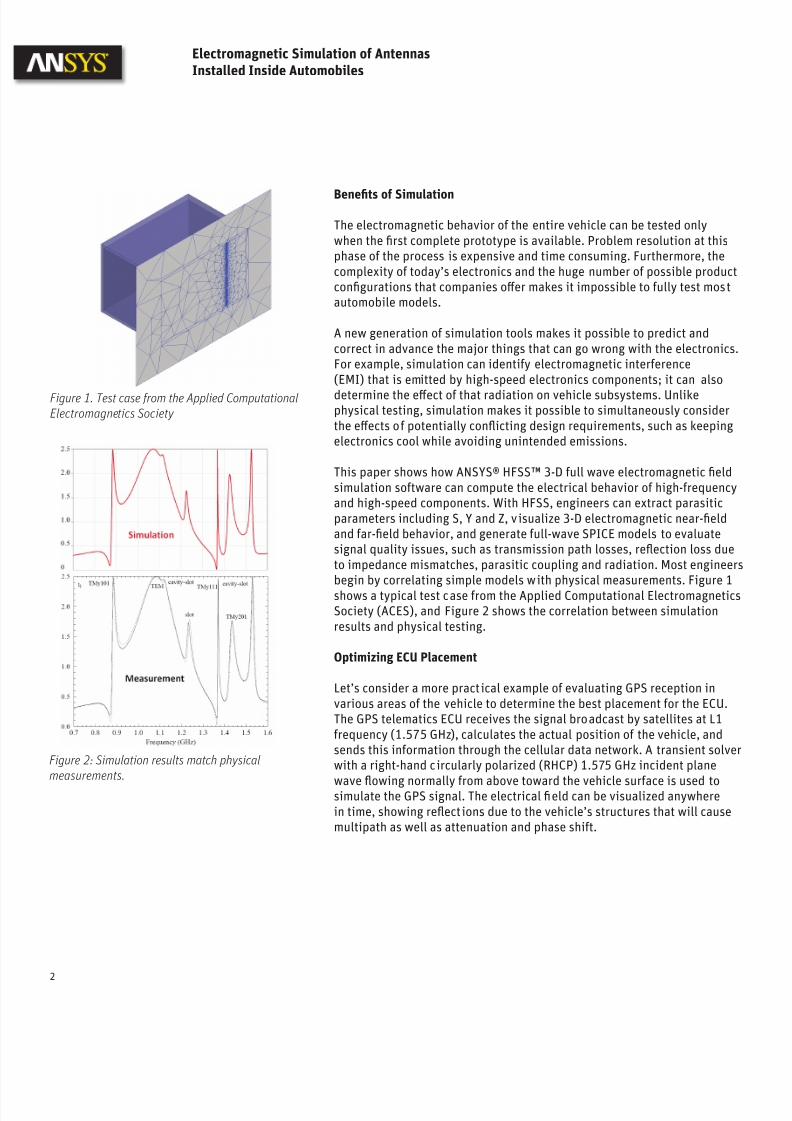
This paper shows how ANSYS® HFSS™ 3-D full wave electromagnetic fieldsimulation software can compute the electrical behavior of high-frequencyand high-speed components. With HFSS, engineers can extract parasiticparameters including S, Y and Z, visualize 3-D electromagnetic near-fieldand far-field behavior, and generate full-wave SPICE models to evaluatesignal quality issues, such as transmission path losses, reflection loss dueto impedance mismatches, parasitic coupling and radiation. Most engineersbegin by correlating simple models with physical measurements. Figure 1shows a typical test case from the Applied Computational ElectromagneticsSociety (ACES), and Figure 2 shows the correlation between simulationresults and physical testing.
Optimizing ECU Placement
Let’s consider a more practical example of evaluating GPS reception invarious areas of the vehicle to determine the best placement for the ECU.The GPS telematics ECU receives the signal broadcast by satellites at L1frequency (1.575 GHz), calculates the actual position of the vehicle, andsends this information through the cellular data network. A transient solverwith a right-hand circularly polarized (RHCP) 1.575 GHz incident plane
wave flowing normally from above toward the vehicle surface is used tosimulate the GPS signal. The electrical field can be visualized anywherein time, showing reflections due to the vehicle’s structures that will causemultipath as well as attenuation and phase shift.
Figure 2: Simulation results match physicalmeasurements.
Electromagnetic Simulation of Antennas
Installed Inside Automobiles
Figure 1. Test case from the Applied ComputationalElectromagnetics Society
7/27/2019 Wp Auto Antenna High Res
http://slidepdf.com/reader/full/wp-auto-antenna-high-res 3/5
3
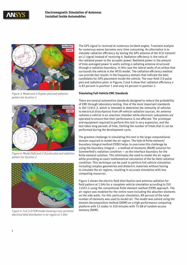
The GPS signal is received at numerous incident angles. Transient analysisfor numerous waves becomes very time consuming. An alternative is tosimulate radiation effi ciency by having the GPS antenna of the ECU transmian L1 signal instead of receiving it. Radiation effi ciency is the ratio of the radiated power to the accepter power. Radiated power is the amountof time-averaged power in watts exiting a radiating antenna structuredthrough a radiation boundary, in this case the lateral walls of an airbox thasurrounds the vehicle in the HFSS model. The radiation effi ciency methodcan provide fast results in the frequency domain that indicate the bestcandidates for GPS placement inside the vehicle. The near-field 3-D polarplot and radiation plots in Figures 3 and 4 show that radiation effi ciency e is 83 percent in position 1 and only 43 percent in position 2.
Simulating Full-Vehicle EMC Standards
There are several automotive standards designed to reduce the probabilityof EMI through laboratory testing. One of the most important standardsis ISO 11451-2, which is intended to determine the immunity of vehiclesto electrical disturbances from off-vehicle radiation sources. An antennaradiates a vehicle in an anechoic chamber while electronic subsystems areoperated to ensure that their performance is not affected. The prototypeand equipment required to perform this test is very expensive, and thetest takes long periods of time, limiting the number of times that it can beperformed during the development cycle.
The greatest challenge in simulating this test is the large computationaldomain required to model the air region. The hybrid finite element/boundary integral method (FEBI) helps to overcome this challenge byusing the boundary integral — a method-of-moments (MoM) solution forSommerfeld’s radiation condition — as the interface boundary for thefinite element solution. This eliminates the need to model the air regionwhile providing an exact mathematical calculation of the far-field radiationcondition. This technique can be used to perform full-vehicle simulationincluding complex geometries and dielectric materials without havingto simulate the air regions, resulting in accurate simulation with lesscomputing resources.
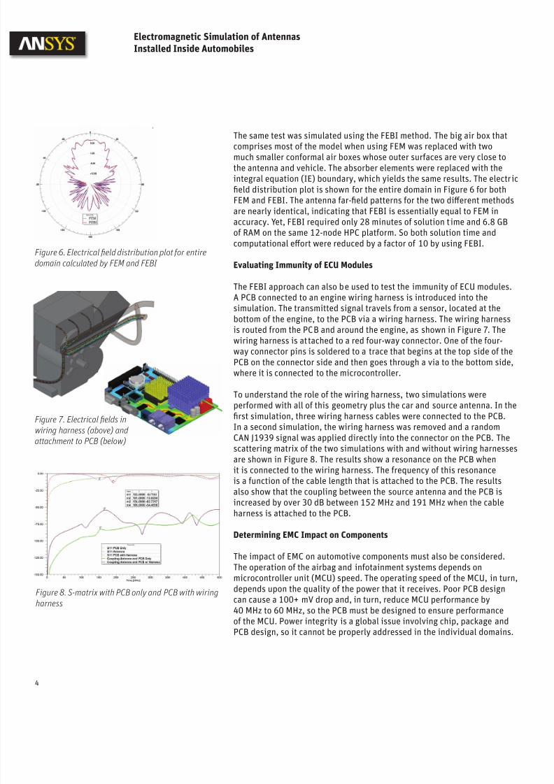
Figure 5 shows the electric field distribution and antenna radiation far-
field pattern at 1 GHz for a complete vehicle simulation according to ISO11451-2 using the conventional finite element method (FEM) approach. Theair region was modeled for the entire room including the absorber elementson the side walls. For this particular simulation, 89 percent of the totalnumber of elements was used to model air. The model was solved using thedomain decomposition method (DDM) on a high-performance computingplatform with 12 nodes in 310 minutes with 75 GB of random-accessmemory (RAM).
Electromagnetic Simulation of Antennas
Installed Inside Automobiles
Figure 3. Model and 3-D polar plot and radiation pattern for location 1
Figure 4. Model (left) and 3-D polar plot and radiation pattern for location 2
Figure 5. Full 3-D FEM model showing cross sectionalelectrical field distribution in air region at 1 GHz
7/27/2019 Wp Auto Antenna High Res
http://slidepdf.com/reader/full/wp-auto-antenna-high-res 4/5
The same test was simulated using the FEBI method. The big air box thatcomprises most of the model when using FEM was replaced with twomuch smaller conformal air boxes whose outer surfaces are very close tothe antenna and vehicle. The absorber elements were replaced with theintegral equation (IE) boundary, which yields the same results. The electricfield distribution plot is shown for the entire domain in Figure 6 for bothFEM and FEBI. The antenna far-field patterns for the two different methodsare nearly identical, indicating that FEBI is essentially equal to FEM inaccuracy. Yet, FEBI required only 28 minutes of solution time and 6.8 GBof RAM on the same 12-node HPC platform. So both solution time andcomputational effort were reduced by a factor of 10 by using FEBI.
Evaluating Immunity of ECU Modules
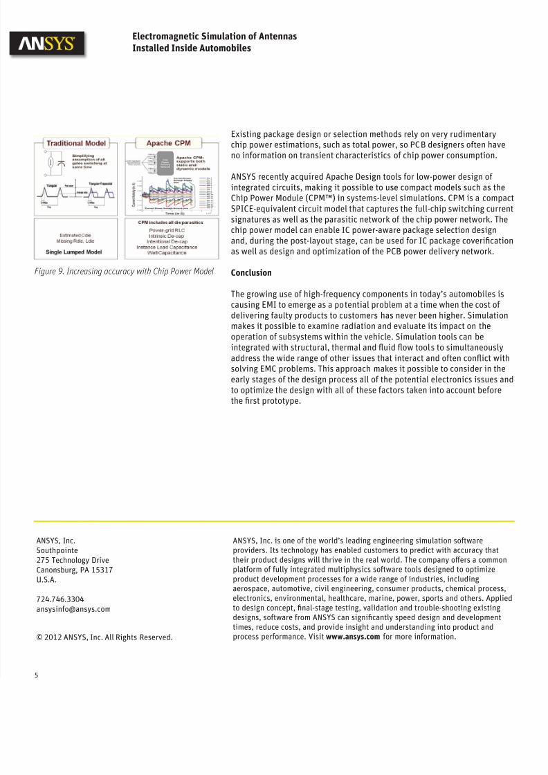
The FEBI approach can also be used to test the immunity of ECU modules.A PCB connected to an engine wiring harness is introduced into thesimulation. The transmitted signal travels from a sensor, located at thebottom of the engine, to the PCB via a wiring harness. The wiring harnessis routed from the PCB and around the engine, as shown in Figure 7. Thewiring harness is attached to a red four-way connector. One of the four-way connector pins is soldered to a trace that begins at the top side of thePCB on the connector side and then goes through a via to the bottom side,where it is connected to the microcontroller.
To understand the role of the wiring harness, two simulations wereperformed with all of this geometry plus the car and source antenna. In thefirst simulation, three wiring harness cables were connected to the PCB.In a second simulation, the wiring harness was removed and a randomCAN J1939 signal was applied directly into the connector on the PCB. Thescattering matrix of the two simulations with and without wiring harnessesare shown in Figure 8. The results show a resonance on the PCB whenit is connected to the wiring harness. The frequency of this resonanceis a function of the cable length that is attached to the PCB. The resultsalso show that the coupling between the source antenna and the PCB isincreased by over 30 dB between 152 MHz and 191 MHz when the cableharness is attached to the PCB.
Determining EMC Impact on Components
The impact of EMC on automotive components must also be considered.The operation of the airbag and infotainment systems depends onmicrocontroller unit (MCU) speed. The operating speed of the MCU, in turn,depends upon the quality of the power that it receives. Poor PCB designcan cause a 100+ mV drop and, in turn, reduce MCU performance by40 MHz to 60 MHz, so the PCB must be designed to ensure performanceof the MCU. Power integrity is a global issue involving chip, package andPCB design, so it cannot be properly addressed in the individual domains.
4
Figure 6. Electrical field distribution plot for entiredomain calculated by FEM and FEBI
Electromagnetic Simulation of Antennas
Installed Inside Automobiles
Figure 8. S-matrix with PCB only and PCB with wiringharness
Figure 7. Electrical fields inwiring harness (above) and attachment to PCB (below)
7/27/2019 Wp Auto Antenna High Res
http://slidepdf.com/reader/full/wp-auto-antenna-high-res 5/5
Existing package design or selection methods rely on very rudimentarychip power estimations, such as total power, so PCB designers often haveno information on transient characteristics of chip power consumption.
ANSYS recently acquired Apache Design tools for low-power design of integrated circuits, making it possible to use compact models such as theChip Power Module (CPM™) in systems-level simulations. CPM is a compactSPICE-equivalent circuit model that captures the full-chip switching currentsignatures as well as the parasitic network of the chip power network. Thechip power model can enable IC power-aware package selection designand, during the post-layout stage, can be used for IC package coverificationas well as design and optimization of the PCB power delivery network.
Conclusion
The growing use of high-frequency components in today’s automobiles iscausing EMI to emerge as a potential problem at a time when the cost of delivering faulty products to customers has never been higher. Simulationmakes it possible to examine radiation and evaluate its impact on theoperation of subsystems within the vehicle. Simulation tools can beintegrated with structural, thermal and fluid flow tools to simultaneouslyaddress the wide range of other issues that interact and often conflict withsolving EMC problems. This approach makes it possible to consider in theearly stages of the design process all of the potential electronics issues andto optimize the design with all of these factors taken into account beforethe first prototype.
5
ANSYS, Inc. is one of the world’s leading engineering simulation softwareproviders. Its technology has enabled customers to predict with accuracy thattheir product designs will thrive in the real world. The company offers a commonplatform of fully integrated multiphysics software tools designed to optimizeproduct development processes for a wide range of industries, includingaerospace, automotive, civil engineering, consumer products, chemical process,electronics, environmental, healthcare, marine, power, sports and others. Appliedto design concept, final-stage testing, validation and trouble-shooting existingdesigns, software from ANSYS can significantly speed design and developmenttimes, reduce costs, and provide insight and understanding into product andprocess performance. Visit www.ansys.com for more information.
ANSYS, Inc.Southpointe275 Technology DriveCanonsburg, PA 15317U.S.A.
© 2012 ANSYS, Inc. All Rights Reserved.
Electromagnetic Simulation of Antennas
Installed Inside Automobiles
Figure 9. Increasing accuracy with Chip Power Model