Embed Size (px)
Citation preview
1 Rev. 3_112013
Wov-N-Wire® Installation instructions
5858 W. 73rd St Bedford Park, IL 60638
(800) 622-2214 (TEL) (708) 325-0400 (TEL) (708) 325-0450 (FAX)
2 Rev. 3_112013
The following installation instructions should be used as a guide for installing Folding Guard Wov-N-Wire® Partitions. Good common sense and appropriate safety precautions must be used during installations. The product may be unstable during installation; accordingly - temporary bracing should be implemented until all hardware is tightened and the product is properly anchored to the floor. Permanent field bracing (Not supplied) may be installed at installer’s/owner’s discretion. Installation problems arising from job site conditions should be referred to a professional installer. Refer product assembly questions to Folding Guard®. Self-Tapping Screw Installation Recommendations: When installing self-tapping screws use a standard variable speed screw gun equipped with an adjustable clutch or depth locating nosepiece. Take care not to over tighten or strip, set the drill accordingly. DO NOT USE IMPACT TYPE GUN WHEN INSTALLING SELF-TAPPING SCREWS. Securely clamp component parts in place before attaching with self-tapping screws. Installer Tips:
Installation is best completed with the help of one or two people. Prior to beginning, please read through all instructions pertinent to your installation. (Doors, panels, etc…) Panels are to be installed horizontally between posts, parallel with the ground. Prior to beginning, if at all possible please lay out the parts where they are to be installed. Make sure all posts are installed perpendicular to the floor; shims (NOT SUPPLIED) may be required. Begin installation at a wall (If your plan calls for a wall connection), corner or an end of a post. Assembly hardware will be installed on the inside of most systems. Installer should eliminate any bolts or hardware protruding into aisle ways or around door openings.
General Information 5858 W. 73RD ST Bedford Park, IL 60638
(800) 622-2214 (Tel.) (708) 325-0400 (Tel.) (708) 325-0450 (Fax) www.foldingguard.com
Tools Required: 5/8 Masonry Bit 5/16 Masonry Bit 5/16
Wrench 7/16 Wrench 9/16
Wrench Hammer Electric Drill (Var. Speed)
Tools Recommended: Ladder Carpenters Level Wire cutters Chalk Line Floor Anchors (NOT
SUPPLIED). Recommended 3/8”-20 X 3¾” Anchor.
Prior to Installation: Prior to beginning installation
please make sure that you have all the parts required for the assembly
Make sure that the installation area is clear of all obstructions.
Read thoroughly all the instructions pertinent to your installation.
Tools Recommended: Shims (NOT SUPPLIED) Drill Bits (Various) Flat Screw Driver Tape Measure Level Rubber Mallet
Wov-N-Wire®
3 Rev. 3_112013
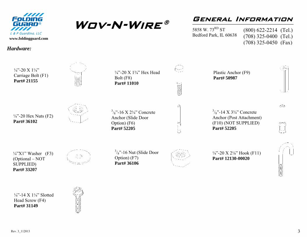
Hardware:
General Information 5858 W. 73RD ST Bedford Park, IL 60638
www.foldingguard.com
(800) 622-2214 (Tel.) (708) 325-0400 (Tel.) (708) 325-0450 (Fax)
Wov-N-Wire ®
¼”-20 Hex Nuts (F2) Part# 36102
¼”-14 X 1¼” Slotted Head Screw (F4) Part# 31149
Plastic Anchor (F9) Part# 50987
3/8”-16 X 2¼” Concrete Anchor (Slide Door Option) (F6) Part# 52205
3/8”-16 Nut (Slide Door Option) (F7) Part# 36106
¼”-20 X 1¾” Hex Head Bolt (F8) Part# 11010
¼”-20 X 1¼” Carriage Bolt (F1) Part# 21155
3/8”-14 X 3¾” Concrete Anchor (Post Attachment) (F10) (NOT SUPPLIED) Part# 52205
¼”-20 X 2⅛” Hook (F11) Part# 12130-00020
¼”X1” Washer (F3) (Optional – NOT SUPPLIED) Part# 33207
4 Rev. 3_112013
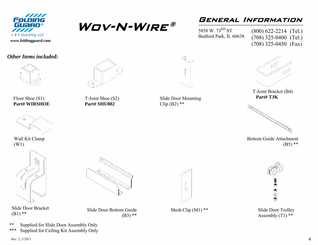
Other Items included:
General Information 5858 W. 73RD ST Bedford Park, IL 60638
www.foldingguard.com
Slide Door Bracket (B1) **
Slide Door Mounting Clip (B2) **
Slide Door Bottom Guide (B3) **
T-Joint Bracket (B4) Part# TJK
Slide Door Trolley Assembly (T1) **
** Supplied for Slide Door Assembly Only *** Supplied for Ceiling Kit Assembly Only
(800) 622-2214 (Tel.) (708) 325-0400 (Tel.) (708) 325-0450 (Fax)
Wov-N-Wire ®
Floor Shoe (S1) Part# WIRSHOE
Wall Kit Clamp (W1)
T-Joint Shoe (S2) Part# SHU002
Bottom Guide Attachment (B5) **
Mesh Clip (M1) **
5 Rev. 3_112013
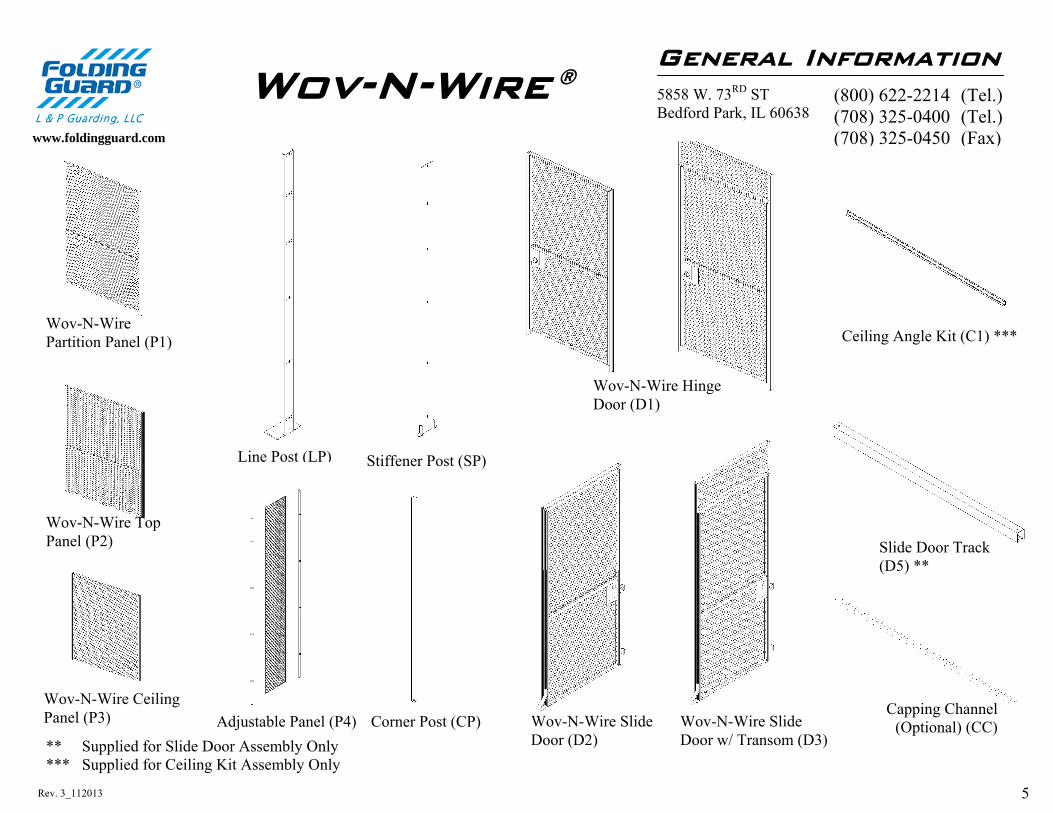
Slide Door Track (D5) **
General Information 5858 W. 73RD ST Bedford Park, IL 60638
www.foldingguard.com
Line Post (LP)
Ceiling Angle Kit (C1) ***
** Supplied for Slide Door Assembly Only *** Supplied for Ceiling Kit Assembly Only
(800) 622-2214 (Tel.) (708) 325-0400 (Tel.) (708) 325-0450 (Fax)
Wov-N-Wire ®
Wov-N-Wire Partition Panel (P1)
Wov-N-Wire Top Panel (P2)
Corner Post (CP) Wov-N-Wire Slide Door (D2)
Capping Channel (Optional) (CC)
Wov-N-Wire Hinge Door (D1)
Wov-N-Wire Ceiling Panel (P3)
Stiffener Post (SP)
Wov-N-Wire Slide Door w/ Transom (D3)
Adjustable Panel (P4)
6 Rev. 3_112013
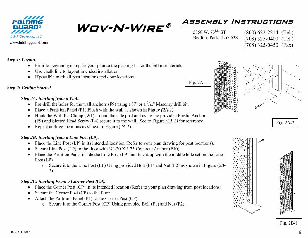
Step 1: Layout.
Prior to beginning compare your plan to the packing list & the bill of materials. Use chalk line to layout intended installation. If possible mark all post locations and door locations.
Step 2: Getting Started Step 2A: Starting from a Wall.
Pre-drill the holes for the wall anchors (F9) using a ⅜” or a 5/16” Masonry drill bit. Place a Partition Panel (P1) Flush with the wall as shown in Figure (2A-1). Hook the Wall Kit Clamp (W1) around the side post and using the provided Plastic Anchor
(F9) and Slotted Head Screw (F4) secure it to the wall. See to Figure (2A-2) for reference. Repeat at three locations as shown in Figure (2A-1).
Step 2B: Starting from a Line Post (LP).
Place the Line Post (LP) in its intended location (Refer to your plan drawing for post locations). Secure Line Post (LP) to the floor with ⅜”-20 X 3.75 Concrete Anchor (F10). Place the Partition Panel inside the Line Post (LP) and line it up with the middle hole set on the Line
Post (LP) o Secure it to the Line Post (LP) Using provided Bolt (F1) and Nut (F2) as shown in Figure (2B-
1). Step 2C: Starting From a Corner Post (CP).
Place the Corner Post (CP) in its intended location (Refer to your plan drawing from post locations) Secure the Corner Post (CP) to the floor. Attach the Partition Panel (P1) to the Corner Post (CP).
o Secure it to the Corner Post (CP) Using provided Bolt (F1) and Nut (F2).
Assembly Instructions 5858 W. 73RD ST Bedford Park, IL 60638
www.foldingguard.com
(800) 622-2214 (Tel.) (708) 325-0400 (Tel.) (708) 325-0450 (Fax)
Wov-N-Wire ®
Fig. 2A-1
Fig. 2A-2
Fig. 2B-1
7 Rev. 3_112013
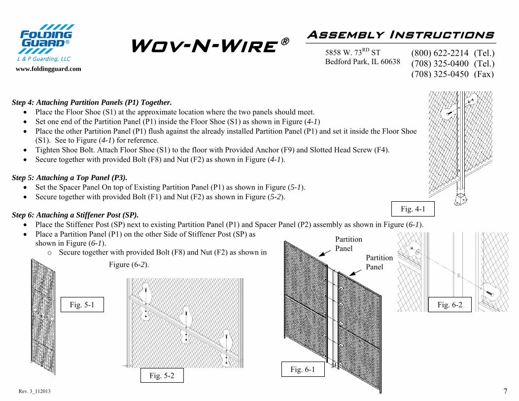
Step 4: Attaching Partition Panels (P1) Together.
Place the Floor Shoe (S1) at the approximate location where the two panels should meet. Set one end of the Partition Panel (P1) inside the Floor Shoe (S1) as shown in Figure (4-1) Place the other Partition Panel (P1) flush against the already installed Partition Panel (P1) and set it inside the Floor Shoe
(S1). See to Figure (4-1) for reference. Tighten Shoe Bolt. Attach Floor Shoe (S1) to the floor with Provided Anchor (F9) and Slotted Head Screw (F4). Secure together with provided Bolt (F8) and Nut (F2) as shown in Figure (4-1).
Step 5: Attaching a Top Panel (P3).
Set the Spacer Panel On top of Existing Partition Panel (P1) as shown in Figure (5-1). Secure together with provided Bolt (F1) and Nut (F2) as shown in Figure (5-2).
Step 6: Attaching a Stiffener Post (SP).
Place the Stiffener Post (SP) next to existing Partition Panel (P1) and Spacer Panel (P2) assembly as shown in Figure (6-1). Place a Partition Panel (P1) on the other Side of Stiffener Post (SP) as
shown in Figure (6-1). o Secure together with provided Bolt (F8) and Nut (F2) as shown in
Figure (6-2).
Assembly Instructions 5858 W. 73RD ST Bedford Park, IL 60638
www.foldingguard.com
(800) 622-2214 (Tel.) (708) 325-0400 (Tel.) (708) 325-0450 (Fax)
Wov-N-Wire ®
Fig. 4-1
Fig. 5-1
Fig. 5-2
Fig. 6-2
Partition Panel
Partition Panel
Fig. 6-1

8 Rev. 3_112013
Step 7: Installing an Adjustable Panel (P4).
Make sure your plan calls for an adjustable panel. Attach one of the angles of the Adjustable Panel (P4) to the already existing structure using provided Bolt (F5) and Nut (F2).
o Make sure the Outside Corner of the Angle is facing the front of the Assembly. See Figure (7-1) for reference. Attach the mesh to the already installed angle clamp it with Mesh Clip (M1) and secure it in the back using Bolt (F5) and Nut (F2). See Figure (7-2)
and (7-3) for reference. Cut the Attached Mesh to the size required so it fits to the next attachment point (that being a post, panel, corner post and/or a wall) using wire
cutters. See Figure (7-4) for reference. Attach the angle to mesh as described earlier. Attach the angle to next attachment point (that being a post, panel, corner post and/or a wall).
Assembly Instructions 5858 W. 73RD ST Bedford Park, IL 60638 www.foldingguard.com
(800) 622-2214 (Tel.) (708) 325-0400 (Tel.) (708) 325-0450 (Fax)
Wov-N-Wire ®
Fig. 7-1 Fig. 7-2 Fig. 7-3 Fig. 7-4

9 Rev. 3_112013
Step 8: Hinge Door Assembly.
Hinge Doors (D1) are shipped set up. o Door frame sizes are exactly as noted on shipping list (i.e. 3’-0” = Outside frame to outside of frame is 36”).
See Figure (8-1) for reference.) If attaching Hinge Door (D1) to Line Post (LP) please consult your Layout Drawing for Post orientation.
o Make sure that the post is facing Flat Side towards the Hinge Door (D1) as shown in Figure (8-2). o Secure together with provided Bolt (F1), and Nut (F2) as shown in Figure (8-5).
If attaching Hinge Door (D1) to a previously installed Partition Panel (P1) o Place the Floor Shoe (S1) at the approximate location where the Hinge Door (D1) and Partition Panel (P1)
should meet. o Set one end of the Partition Panel (P1) inside the Floor Shoe (S1) as shown in Figure (8-3) o Place the frame end of the Hinge Door (D1) flush against the already installed Partition Panel (P1) and set it
inside the Floor Shoe (S1). See to Figure (8-4) for reference. o Secure together with provided Bolt (F8) and Nut (F2) as shown in Figure (8-4).
If attaching Hinge Door (D1) to a Wall o Place the Hinge Door (D1) flush with the wall as shown in Figure (2A-2). o Hook the Wall Kit Clamp (W1) around the side post and using the provided Plastic Anchor (F9) and Slotted Head
Screw (F4) secure it to the wall. See to Figure (2A-2) for reference. o Repeat at three locations as shown in Figure (2A-1).
Hinge Door Assembly 5858 W. 73RD ST Bedford Park, IL 60638
www.foldingguard.com
(800) 622-2214 (Tel.) (708) 325-0400 (Tel.) (708) 325-0450 (Fax)
Wov-N-Wire ®
Fig. 8-2 Fig. 8-4 Fig. 8-5 Fig. 8-3
Fig. 8-1
All Dimensions shown are Inside of posts
Post spacing for Door Assembly

10 Rev. 3_112013
Step 9: Slide Door Assembly. Step 9A: Frame Attachment. Slide Door (D2) is shipped partially set up.
o Door frame sizes are exactly as noted on shipping list (i.e. 3’-0” = Outside frame to outside of frame is 36”). See Figure (9A-1) for reference.)
If attaching Slide Door Frame (D2) to Line Post (LP) please consult your Layout Drawing for Post orientation. o Make sure that the post is facing Flat Side towards the Slide Door (D2) as shown in Figure (9A-3). (Shown
from Inside) o Secure together with provided Bolt (F1) and Nut (F2) as shown in Figure (9A-2).
If attaching Slide Door Frame (D2) to a previously installed Partition Panel (P1) o Place the Floor Shoe (S1) at the approximate location where the Slide Door (D2) and Partition Panel (P1)
should meet. o Set one end of the Partition Panel (P1) inside the Floor Shoe (S1) as shown in Figure (9A-2). o Place the frame end of the Slide Door (D2) flush against the already installed Partition Panel (P1) and set it
inside the Floor Shoe (S1). o Secure together with provided Bolt (F8) and Nut (F2) as shown in Figure (9A-2).
If attaching Slide Door (D2) to a Wall o Make sure that the Sliding Door (D2) is going to be sliding AWAY from the wall. o Place the Slide Door (D2) flush with the wall. o Hook the Wall Kit Clamp (W1) around the side post and using the
provided Plastic Anchor (F9) and Slotted Head Screw (F4) secure it to the wall.
o Repeat at three locations as shown in Figure (9A-4).
Slide Door Assembly 5858 W. 73RD ST Bedford Park, IL 60638
www.foldingguard.com
(800) 622-2214 (Tel.) (708) 325-0400 (Tel.) (708) 325-0450 (Fax)
Wov-N-Wire ®
Fig. 9A-2 Fig. 9A-3 Fig. 9A-4
Fig. 9A-1
All Dimensions sown are Inside of posts
Post spacing for Door Assembly

11 Rev. 3_112013
Step 9B: Slide Door Track (D5) Assembly.
Attach the Slide Door Bracket (B1) to the already installed panels using the provided Slide Door Mounting Clip (B2) and Mesh Clip (M1). Clamp it to the mesh via Bolt (F5) and Nut (F2). See Figure (9B-1) for reference.
o The bottom of the brackets should be level and flush with the top of the frame opening. Slide the Slide Door Bracket (B1) over the Sliding Channel (D5). See Figure (9B-2) for reference.
o DO NOT TIGHTEN THE BOLTS ON THE SLIDE DOOR BRACKET (B1)
Step 9C: Slide Door (D2), (D3) and Trolley (T1) Assembly. Insert the Attach the Trolley assembly (T1) to the top of the door by inserting it into the existing holes at the top of the door. For reference use
Figure (9C-1).
Step 9D: Slide Door (D2), (D3) and installed Slide Door Track (D5) Assembly. Slide the Assembled Door (D2), (D3) into the attached Slide Channel. Slide the Door into the closed position and adjust the Trolley Assembly so the Door (D2), (D3) closes completely. Tighten the Bolts on the Slide Door Bracket. See Figure (9D-1) for reference.
Slide Door Assembly 5858 W. 73RD ST Bedford Park, IL 60638
www.foldingguard.com
(800) 622-2214 (Tel.) (708) 325-0400 (Tel.) (708) 325-0450 (Fax)
Wov-N-Wire ®
Fig. 9B-1 Fig. 9B-2 Fig. 9C-1
Fig. 9D-1
T1
12 Rev. 3_112013
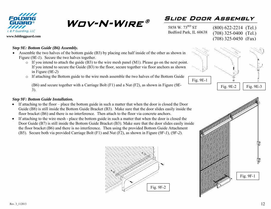
Step 9E: Bottom Guide (B6) Assembly. Assemble the two halves of the bottom guide (B3) by placing one half inside of the other as shown in
Figure (9E-1). Secure the two halves together. o If you intend to attach the guide (B3) to the wire mesh panel (M1). Please go on the next point.
If you intend to secure the Guide (B3) to the floor, secure together via floor anchors as shown in Figure (9E-2)
o If attaching the Bottom guide to the wire mesh assemble the two halves of the Bottom Guide
(B6) and secure together with a Carriage Bolt (F1) and a Nut (F2), as shown in Figure (9E-3).
Step 9F: Bottom Guide Installation. If attaching to the floor – place the bottom guide in such a matter that when the door is closed the Door
Guide (B8) is still inside the Bottom Guide Bracket (B3). Make sure that the door slides easily inside the floor bracket (B6) and there is no interference. Then attach to the floor via concrete anchors.
If attaching to the wire mesh - place the bottom guide in such a matter that when the door is closed the Door Guide (B7) is still inside the Bottom Guide Bracket (B3). Make sure that the door slides easily inside the floor bracket (B6) and there is no interference. Then using the provided Bottom Guide Attachment (B5). Secure both via provided Carriage Bolt (F1) and Nut (F2), as shown in Figure (9F-1), (9F-2).
Slide Door Assembly 5858 W. 73RD ST Bedford Park, IL 60638 www.foldingguard.com
(800) 622-2214 (Tel.) (708) 325-0400 (Tel.) (708) 325-0450 (Fax)
Wov-N-Wire ®
Fig. 9E-1 Fig. 9E-2 Fig. 9E-3
Fig. 9F-1
Fig. 9F-2
13 Rev. 3_112013
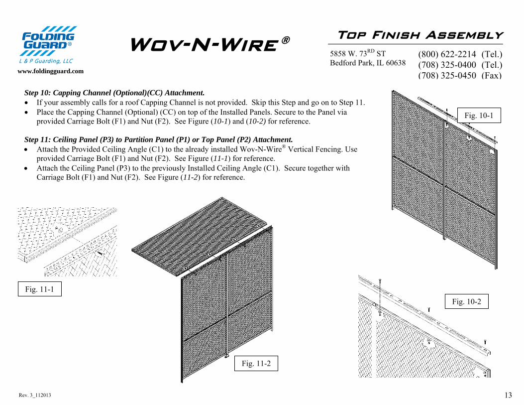
Step 10: Capping Channel (Optional)(CC) Attachment. If your assembly calls for a roof Capping Channel is not provided. Skip this Step and go on to Step 11. Place the Capping Channel (Optional) (CC) on top of the Installed Panels. Secure to the Panel via
provided Carriage Bolt (F1) and Nut (F2). See Figure (10-1) and (10-2) for reference. Step 11: Ceiling Panel (P3) to Partition Panel (P1) or Top Panel (P2) Attachment. Attach the Provided Ceiling Angle (C1) to the already installed Wov-N-Wire® Vertical Fencing. Use
provided Carriage Bolt (F1) and Nut (F2). See Figure (11-1) for reference. Attach the Ceiling Panel (P3) to the previously Installed Ceiling Angle (C1). Secure together with
Carriage Bolt (F1) and Nut (F2). See Figure (11-2) for reference.
Top Finish Assembly 5858 W. 73RD ST Bedford Park, IL 60638
www.foldingguard.com
(800) 622-2214 (Tel.) (708) 325-0400 (Tel.) (708) 325-0450 (Fax)
Wov-N-Wire ®
Fig. 11-1
Fig. 11-2
Fig. 10-1
Fig. 10-2

14 Rev. 3_112013
Step 12: Ceiling Angle (C1), Wall and Ceiling Panel (P3) Attachment..
Pre-drill the holes for the wall anchors (F9) using a ⅜” or a 5/16” Masonry drill bit. Attach The Ceiling Angle (C1) to the wall with the outside facing down use the provided
Plastic Anchor (F9) and Slotted Head Screw (F4) to secure it in place. See to Figure (12-1) for reference.
Place the Ceiling Panel (P3) on top of the attached Ceiling Angle (C1). Insert the provided Hooks (F11) through the holes and around the wire in the Ceiling Panel
(P3), secure on the bottom with the provided Nut (F2). See to Figure (12-2) and (12-3) for reference.
Top Finish Assembly 5858 W. 73RD ST Bedford Park, IL 60638
www.foldingguard.com
(800) 622-2214 (Tel.) (708) 325-0400 (Tel.) (708) 325-0450 (Fax)
Wov-N-Wire ®
Fig. 12-1
Fig. 12-2
Fig. 12-3