Embed Size (px)
Citation preview

WOST 2011
Dynamic Boundary Samples
for Robust NVH Design Using
Smart Simulation Methods
© TRW Automotive Holdings Corp. 2011
Joachim Noack
Dr. Hans Martin Giese
24th November 2011Hans Giese, Dr.-Ing.
Engineering Technologies
Specialist CAE
TRW Automotive - Lucas Varity GmbH
phone: +49(0)261895-2075
fax: +49(0)261895-62075
e-mail: [email protected]

Abstract
Dynamic Boundary Samples for Robust NVH Design Using Smart Simulation Methods
� The current market situation in for wheel brakes requires a high performance quality inregard to NVH, not only in the development phase, also later in the field. In order to avoidwarranty issues there is a need to design and test the brake design for NVH robustnesspurpose. The major dynamic variance in a brake system is usually the rotor variance andthe scatter of the lining; therefore TRW is using a standardized robustness test approachin the NVH process to validate the brake NVH robustness by rotor and pad variations.Here based on existing parts close to production start minimum and maximum frequencyparts, respectively minimum and maximum compressibility linings are selected andtested. For the casted brake parts, carrier and housing, the expected frequency drifts areexpected by maximum 3% over time based on measurements over production life ofcasting tools and production cycle. Supplier changes can cause a shift in theeigenfrequencies as well, but all changes will be within the limit of the drawing
© TRW Automotive Holdings Corp. 2011
eigenfrequencies as well, but all changes will be within the limit of the drawingtolerances. The challenge is now to identify the possible frequency scatter based ondrawing tolerances in order to limit the frequency scatter by an intelligent adjustment ofthe tolerances and to define exact geometries for boundary samples, representingminimum and maximum eigenfrequencies for specific eigenmodes. This will allow TRWto test the extreme frequency situations, possible based on the drawing limits. TRWdeveloped a simulation approach, which allows the identification of the frequency limitsfor all possible geometrical situations. With sensitivity studies the parameter importanceis evaluated and for the relevant frequencies geometrical optimizations are performed todefine the physical boundary samples. For NVH robustness tests these geometries canbe produced and validated.
2
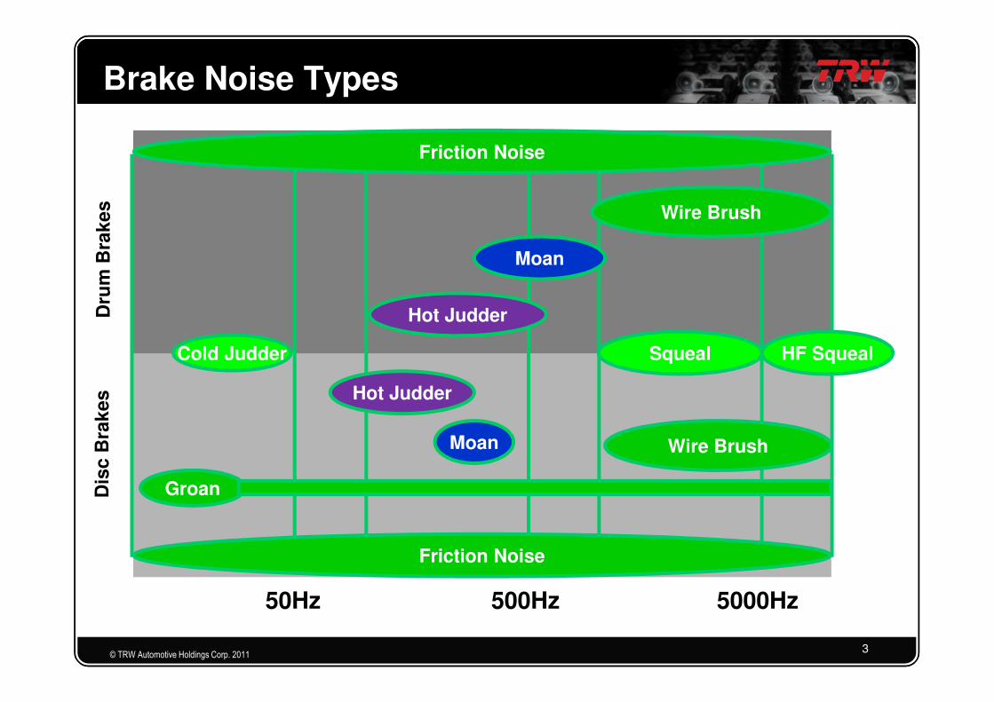
Brake Noise TypesD
rum
Bra
ke
s
Friction Noise
Cold Judder
Hot Judder
Moan
Wire Brush
Squeal HF Squeal
© TRW Automotive Holdings Corp. 2011
Dis
c B
rak
es
Friction Noise
50Hz 500Hz 5000Hz
Cold Judder
Hot Judder
Groan
Squeal HF Squeal
Wire BrushMoan
3
Motivation
� NVH field complaints and warranty costs
� Permanently increasing customer requirements andtargets
© TRW Automotive Holdings Corp. 2011
� CAE helps to mitigate NVH risk by
– Robustness testing � Development
– Production NVH quality control � Production
4

Simulation Targets
� CAE is needed to investigate possible frequency scatter
based on drawing parameters and to define dynamic
boundary samples
���� Dynamic boundary samples are parts with minimum,
respectively maximum eigenfrequencies for certain
© TRW Automotive Holdings Corp. 2011
respectively maximum eigenfrequencies for certain
eigenmodes
� Definition of frequency scatter for production drawings
5

CAE Process for NVH Boundary Samples
FEA (component modal Analysis) and correlation to test
Parameterization of Finite Element Model
Robustness / Sensitivity study and Optimization
© TRW Automotive Holdings Corp. 2011
Redesign of FE results (CAD)
Eigenfrequencies on Drawing
Prototyping
6

Brake Carrier Mode Shapes
Mode 1
Mode 2
Mode 6
Mode 5
Mode 7 Mode 13
Mode 12
Mode 10
defined as
© TRW Automotive Holdings Corp. 2011
Mode 3
Mode 2
Mode 14
Mode 7 Mode 13
Mode 4 Mode 15
Mode 8
Mode 9
as critical
7

CAE parameterization Solutions
Basically two methods to parameterize the FE problem are possible
� Parameter Setup 1
◦ Parameterization based on geometry items / CAD
© TRW Automotive Holdings Corp. 2011
� Parameter Setup 2
◦ Parameterization based on finite element morphing
handles
8

Parameter Setup 1
© TRW Automotive Holdings Corp. 2011
• Parameters in CAD � Effort for design department
• Dependencies of parameters are not allowing simple model
manipulation
���� Parameter manipulation not robust, CAD systems are often
not able to calculate geometries!
9

Parameter Setup 2
• Parameters = node sets
© TRW Automotive Holdings Corp. 2011
� final geometry needs to be translated back to CAD
���� Redesign!
� For prototyping STL can be used directly
• Variation range = drawing tolerances
• Mesh morphing
10

Target
�Design space for the optimization / robustness
problem is the drawing tolerance of the
component
© TRW Automotive Holdings Corp. 201111

Sensitivity Study
Example for one eigenmode
© TRW Automotive Holdings Corp. 2011
• Parameter field is scanned by random variation of parameters
12

Influence of Parameter Setup
� Parameter Setup 1
(CAD based)
� Parameter Setup 2
(FEA based)
© TRW Automotive Holdings Corp. 2011
(CAD based)
◦ 175 independent
parameters (300 at all)
◦ 500 runs (only 251 runs
lead into successful
geometries!)
(FEA based)
– 25 parameters
– 50 runs
13

Carrier Frequency Variation
frequency scatterfr
eq
uen
cy s
catt
er
in %
© TRW Automotive Holdings Corp. 2011
yellow area = relevant component eigenfrequencies for critical noise frequency
freq
uen
cy s
catt
er
mode no.
14

Numerical Optimization
© TRW Automotive Holdings Corp. 201115

Redesign in CAD
Case Study:
• Brown: original nominal CAD
• Blue: CAE boundary sample proposal,redesign in CAD
Parameter Setup 1 (CAD based)
© TRW Automotive Holdings Corp. 2011
Parameter Setup 1 (CAD based)
• Direct usage of CAD parameter
Parameter Setup 2 (FEA based)
• Finite element solution needs redesign in CADnecessary
• STL data can be used to support
16

Summary and Conclusion
� CAE sensitivity / robustness studies and parameteroptimization are useful to define dynamic boundarysamples of brake components
� Based on the simulation results
– Prototypes can be produced
© TRW Automotive Holdings Corp. 2011
– Prototypes can be produced
– Frequency ranges on drawings can be defined
�CAE Approach mitigates NVH risk in
production and increases NVH quality and
robustness
17