Embed Size (px)
Citation preview
4 American Metric® Corporation
WORM SCREW REDUCTION GEARS AND MOTOR REDUCTION GEARS
1. 0 INTRODUCTIONAmetric® intends to boost its presence in the marketplace bydrawing on its twin strengths of quality and an ongoingcommitment to product improvement aimed at satisfying all ourcustomer’s needs. Our versatility allows us to satisfy requestsfor special reduction gears. Each unit is tested prior toshipping for optimum performance. All units are handcraftedby artisans in Italy.
1.1 SYMBOLSP = Power (RD)P1 = Power (FRD)Pu = Output Poweri = Gear Ratioit = Total Gear Ratio (for combined gears)i1 = 1° Reduction Gear Ratioi2 = 2° Reduction Gear Ratioic = Gear Ratio with Pretorqueitc = Total Gear Ratio with Pretorquen1 = Input RPMn2 = Output RPMM1 = Output Twisting Moment (RD)M1’ = Output Twisting Moment (FRD)M2 = Twisting Moment RequestedMc = Twisting Moment CalculatedRd = Dynamic EfficiencyRs = Static EfficiencyFG = Guarantee FactorFs = Service FactorCR = Low-Speed Shaft Radial LoadCA = Low-Speed Shaft Axial LoadCRV = High-Speed Shaft Radial LoadCAV = High-Speed Shaft Axial Load
1.2 UNITS OF MEASUREMENTP KWP1 KW 1KW = 1.36 HPPu KWn1 RPMn2 RPMM1 NmM2 Nm 1Nm = 0.1daNmMC Nm 1Nm = 0.1 KgmCR NCA N 1N = 0.1 daNCRV N 1N = 0.1 KgCAV N
1.3 POWERP (KW) – Applicable input power relating to velocity n1, andto a service factor Fs = 1. (see reduction gear performancetables on page 32)
20°
1
1
1
30°
1.05
1.03
1.01
40°
1.2
1.15
1.08
50°
1.4
1.32
1.22
Uniform Load
Load with Moderate Impact
Load with High Impact
Ambient Temperature (C°)Type of Load
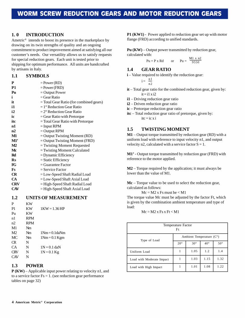
Temperature FactorFt
P1 (KW1) - Power applied to reduction gear set up with motorflange (FRD) according to unified standards.
Pu (KW) – Output power transmitted by reduction gear,calculated with:
1.4 GEAR RATIOi – Value required to identify the reduction gear:
it – Total gear ratio for the combined reduction gear, given by:it = i1 x i2
i1 – Driving reduction gear ratioi2 – Driven reduction gear ratioic – Pretorque reduction gear ratioitc – Total reduction gear ratio of pretorque, given by:
itc = ic x i
1.5 TWISTING MOMENTM1 – Output torque transmitted by reduction gear (RD) with auniform load with reference to input velocity n1, and outputvelocity n2, calculated with a service factor S = 1.
M1’ - Output torque transmitted by reduction gear (FRD) withreference to the motor applied.
M2 – Torque required by the application; it must always belower than the value of M1.
Mc – Torque value to be used to select the reduction gear,calculated as follows:
Mc = M2 x Fs must be < M1The torque value Mc must be adjusted by the factor Ft, whichis given by the combination ambient temperature and type ofload:
Mc = M2 x Fs x Ft < M1
n1n2
i =
M1 x n29550Pu = P x Rd or Pu =
American Metric® Corporation 5
WORM SCREW REDUCTION GEARS AND MOTOR REDUCTION GEARS
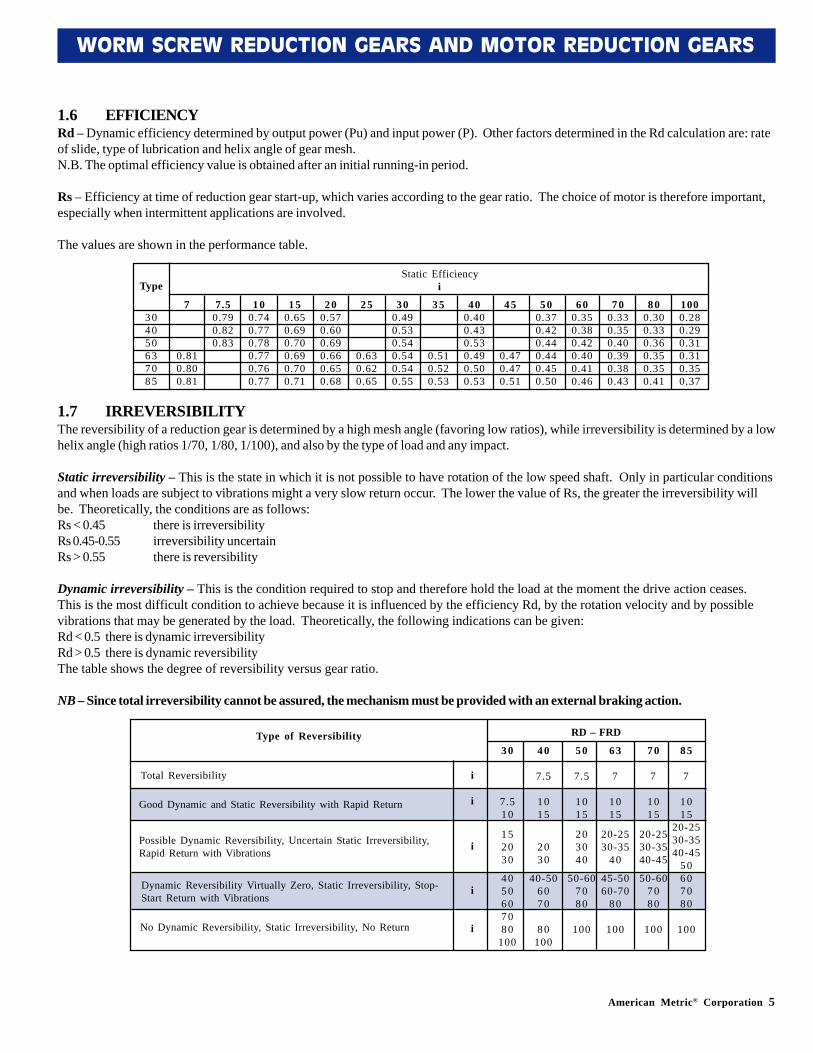
1.6 EFFICIENCYRd – Dynamic efficiency determined by output power (Pu) and input power (P). Other factors determined in the Rd calculation are: rateof slide, type of lubrication and helix angle of gear mesh.N.B. The optimal efficiency value is obtained after an initial running-in period.
Rs – Efficiency at time of reduction gear start-up, which varies according to the gear ratio. The choice of motor is therefore important,especially when intermittent applications are involved.
The values are shown in the performance table.
1.7 IRREVERSIBILITYThe reversibility of a reduction gear is determined by a high mesh angle (favoring low ratios), while irreversibility is determined by a lowhelix angle (high ratios 1/70, 1/80, 1/100), and also by the type of load and any impact.
Static irreversibility – This is the state in which it is not possible to have rotation of the low speed shaft. Only in particular conditionsand when loads are subject to vibrations might a very slow return occur. The lower the value of Rs, the greater the irreversibility willbe. Theoretically, the conditions are as follows:Rs < 0.45 there is irreversibilityRs 0.45-0.55 irreversibility uncertainRs > 0.55 there is reversibility
Dynamic irreversibility – This is the condition required to stop and therefore hold the load at the moment the drive action ceases.This is the most difficult condition to achieve because it is influenced by the efficiency Rd, by the rotation velocity and by possiblevibrations that may be generated by the load. Theoretically, the following indications can be given:Rd < 0.5 there is dynamic irreversibilityRd > 0.5 there is dynamic reversibilityThe table shows the degree of reversibility versus gear ratio.
NB – Since total irreversibility cannot be assured, the mechanism must be provided with an external braking action.
7
0.810.800.81
7.50.790.820.83
100.740.770.780.770.760.77
150.650.690.700.690.700.71
200.570.600.690.660.650.68
25
0.630.620.65
300.490.530.540.540.540.55
35
0.510.520.53
400.400.430.530.490.500.53
45
0.470.470.51
500.370.420.440.440.450.50
600.350.380.420.400.410.46
700.330.350.400.390.380.43
800.300.330.360.350.350.41
1000.280.290.310.310.350.37
304050637085
Static EfficiencyiType
30
7.510
152030
4050607080
100
40
7.5
1015
2030
40-506070
80100
50
7.5
1015
203040
50-607080
100
63
7
1015
20-2530-35
40
45-5060-70
80
100
70
7
1015
20-2530-3540-45
50-607080
100
85
7
1015
20-2530-3540-45
50607080
100No Dynamic Reversibility, Static Irreversibility, No Return
Dynamic Reversibility Virtually Zero, Static Irreversibility, Stop-Start Return with Vibrations
Possible Dynamic Reversibility, Uncertain Static Irreversibility,Rapid Return with Vibrations
Good Dynamic and Static Reversibility with Rapid Return
Total Reversibility
Type of Reversibility RD – FRD
i
i
i
i
i
6 American Metric® Corporation
WORM SCREW REDUCTION GEARS AND MOTOR REDUCTION GEARS
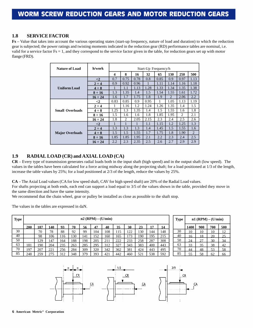
1.8 SERVICE FACTORFs – Value that takes into account the various operating states (start-up frequency, nature of load and duration) to which the reductiongear is subjected; the power ratings and twisting moments indicated in the reduction gear (RD) performance tables are nominal, i.e.valid for a service factor Fs = 1, and they correspond to the service factor given in the table, for reduction gears set up with motorflange (FRD).
1.9 RADIAL LOAD (CR) and AXIAL LOAD (CA)CR – Every type of transmission generates radial loads both in the input shaft (high speed) and in the output shaft (low speed). Thevalues in the tables have been calculated for a force acting midway along the projecting shaft; for a load positioned at 1/3 of the length,increase the table values by 25%; for a load positioned at 2/3 of the length, reduce the values by 25%.
CA – The Axial Load values (CA for low speed shaft, CAV for high speed shaft) are 20% of the Radial Load values.For shafts projecting at both ends, each end can support a load equal to 3/5 of the values shown in the table, provided they move inthe same direction and have the same intensity.We recommend that the chain wheel, gear or pulley be installed as close as possible to the shaft stop.
The values in the tables are expressed in daN.
200
181197248
1877098
129190207259
14078
106147204221275
9388
116164235256312
7092
130188263284348
5699
141198285309379
47104152205295320393
40108160211312342421
35115165222327362442
30122173233343381460
23130190258383424521
17144195287400443538
14148215308443495592
304050637085
n2 (RPM) – (U/min)Type
1400101624334455
900101827354858
700102030385362
500122534425866
304050637085
Type n1 (RPM) – (U/min)
5001.131.181.381.722.2
1.191.51.82.12.61.31.62
2.52.9
2500.971.161.351.612.061.131.41.62
2.51.251.551.902.42.9
1300.91.141.341.55
21.051.351.551.952.41.21.51.82.32.7
650.851.111.331.541.91
1.261.51.852.31.151.451.752.22.6
320.81
1.281.51.80.951.241.41.82.151.11.41.72.12.5
160.780.961.131.41.750.91.21.351.62.05
11.31.551.952.35
80.750.921.11.351.70.851.161.31.621
1.31.51.852.3
40.70.91
1.31.60.83
11.251.51.81
1.31.51.852.2
<22 ÷ 44 ÷ 88 ÷ 16
16 ÷ 24<2
2 ÷ 44 ÷ 88 ÷ 16
16 ÷ 24<2
2 ÷ 44 ÷ 88 ÷ 16
16 ÷ 24
Uniform Load
Small Overloads
Major Overloads
Nature of Load h/work Start-Up Frequency/h
American Metric® Corporation 7
WORM SCREW REDUCTION GEARS AND MOTOR REDUCTION GEARS
1.10 LUBRICATIONOur reduction gears are supplied life-lubricated with synthetic oil. However a plug is fitted for use if necessary. Unless specificrequests are made, the type of oil used is “TIVELA OIL SC 320”.
1.11 INSTALLATIONIt is important to secure the motor reduction gear so that vibrations are not transmitted during operation, because they are a source ofnoise and premature wear due to variable fatigue. With regard to continuous starts under load, we recommend that the motor beprotected with thermal probes so that overheating due to overloads does not lead to coil meltdown.
1.12 PAINTINGUp to and including size 70, the reduction gears are made from aluminum and no painting of any kind is provided.From size 85 up, the reduction gears are made from cast iron and painted.For paint specification requests, please contact our Special Products Department.
1.13 MAINTENANCESince our reduction gears are supplied with life-lubricated synthetic oil, no particular maintenance is required apart from externalcleaning. Do not use solvents for cleaning as they may damage the seal rings and gaskets.
1.14 TECHNICAL SPECIFICATIONSTechnical specifications shown in this catalog are subject to change without notification. Please contact our customer service team forthe most current information.
1.15 WARRANTYThere are no warranties, of merchantability, fitness for purpose, or express, that extend beyond the description contained herein. Theparties agree that the buyer’s sole exclusive remedy against the seller shall be repair or replacement of defective parts of goods. Thebuyer agrees that no other remedy, including, but not limited to, consequential and incidental damages, shall be available to him.

American Metric® Corporation 9
WORM SCREW REDUCTION GEARS AND MOTOR REDUCTION GEARS
AMETRIC® gearboxes are appreciated for their reliability and noise-free operation, which are crucial characteristics of a good product.This has been achieved by the systematic control of processes, from selecting the materials right through to assembly, every singlephase of which is performed manually by trained personnel.
Up to and including size 70, the external parts (box, flanges, feet, etc.) are made from SGALSI 91 UNI 7369 aluminum. From size 85 upthey are made from mechanical cast iron G20-UNI 5007.
•TRANSMISSION MECHANISMUp to size 50, there are 11 gear ratios: for sizes 63, 70 and 85 there are 14 gear ratios (personalized gear ratios can be considered onrequest).
•WORM GEARSMade from nickel-chrome-molybdenum steel and case hardened to obtain a specific surface hardness (ensuring long life and wearstrength) and a tough, elastic core to withstand mechanical impact. The profile is ground to an involute shape (Z1).
•CROWN GEARSBuilt with central hub in cast iron (G20-UNI 5007), onto which a bronze layer is cast (B14-UNI 1701).
•BEARINGSBall type with wide face; from center distance 50 taper roller bearings are mounted on the high speed shaft (WORM GEAR).
•SEAL RINGSDouble lip seal rings are fitted on all types to ensure enhanced tightness.
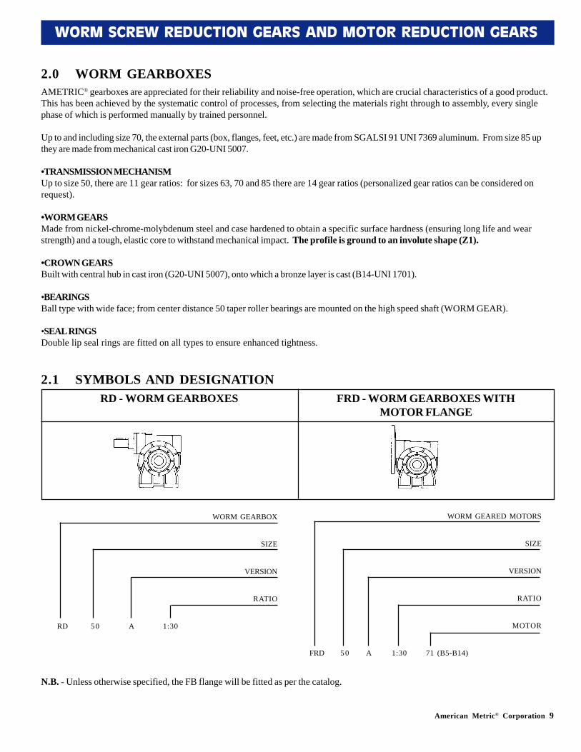
RD - WORM GEARBOXES FRD - WORM GEARBOXES WITHMOTOR FLANGE
WORM GEARED MOTORS
SIZE
VERSION
RATIO
MOTOR
FRD 50 A 1:30 71 (B5-B14)
WORM GEARBOX
SIZE
VERSION
RATIO
RD 50 A 1:30
2.0 WORM GEARBOXES
N.B. - Unless otherwise specified, the FB flange will be fitted as per the catalog.
2.1 SYMBOLS AND DESIGNATION
10 American Metric® Corporation
WORM SCREW REDUCTION GEARS AND MOTOR REDUCTION GEARS
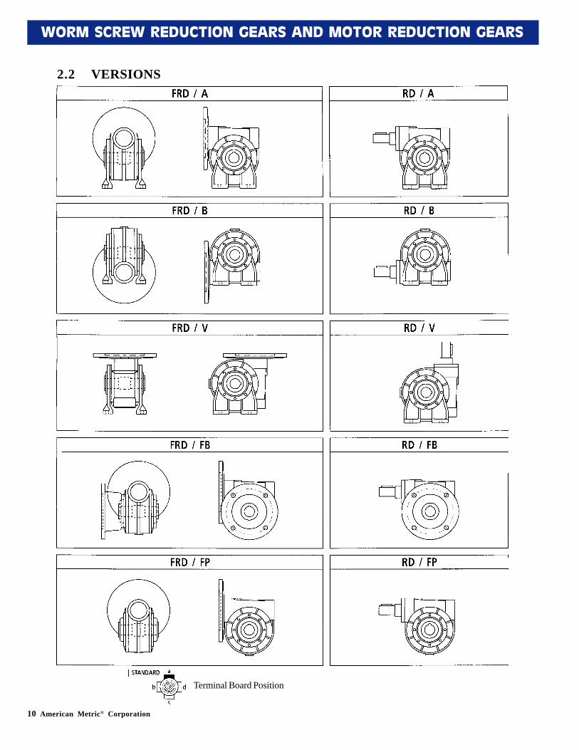
2.2 VERSIONS
Terminal Board Position
American Metric® Corporation 11
WORM SCREW REDUCTION GEARS AND MOTOR REDUCTION GEARS
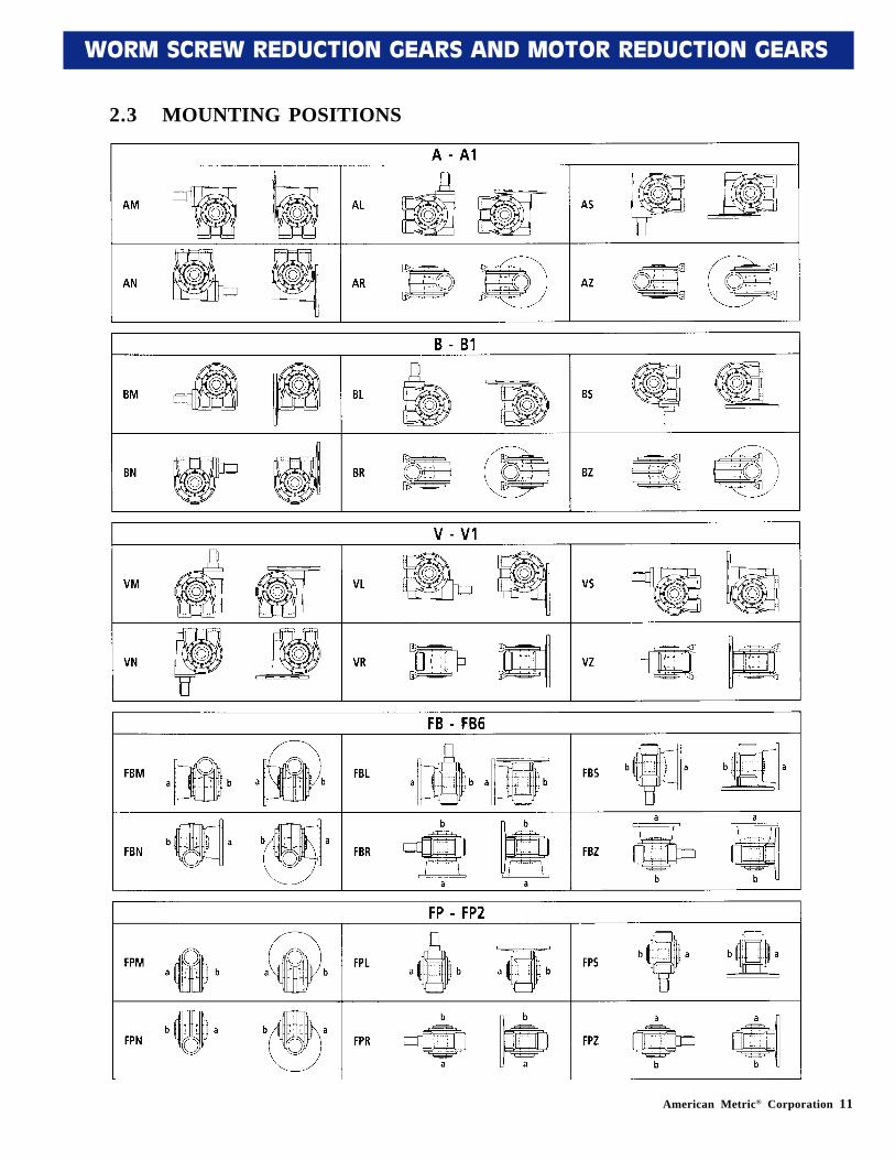
2.3 MOUNTING POSITIONS
12 American Metric® Corporation
WORM SCREW REDUCTION GEARS AND MOTOR REDUCTION GEARS
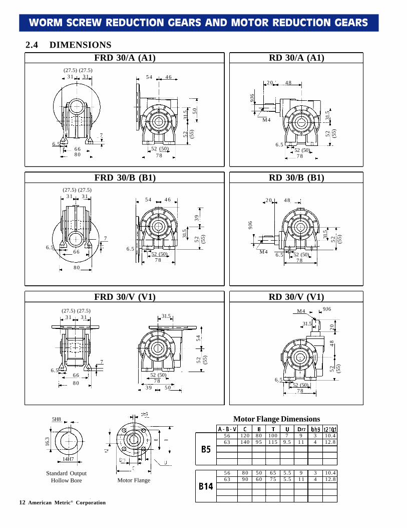
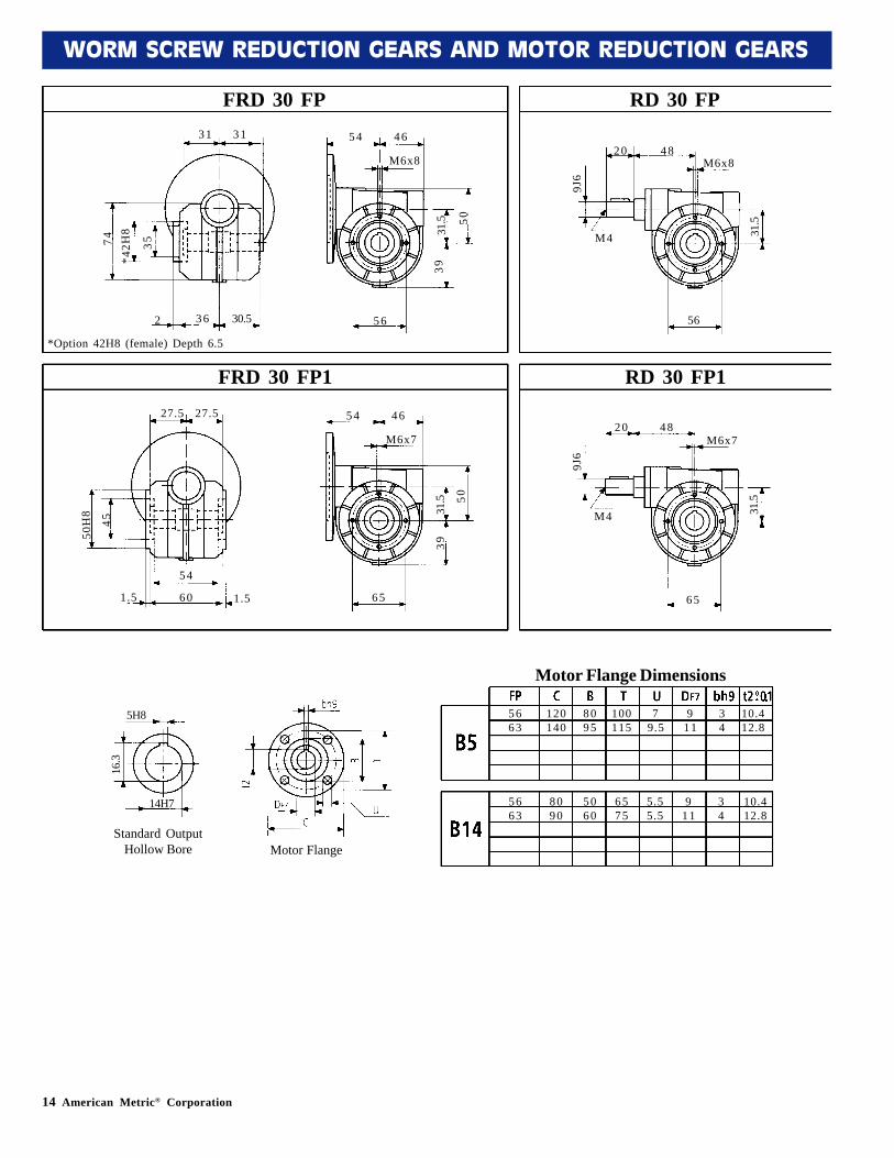
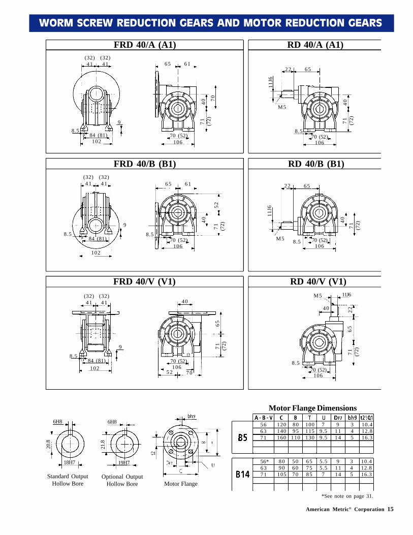
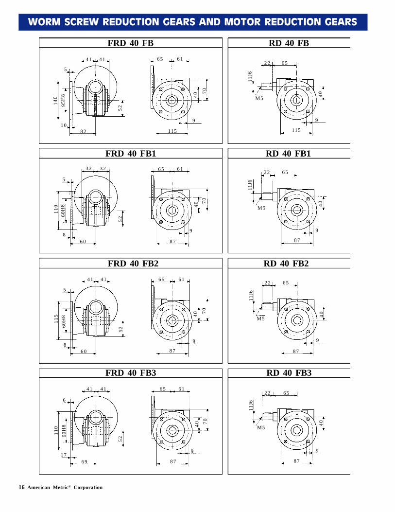
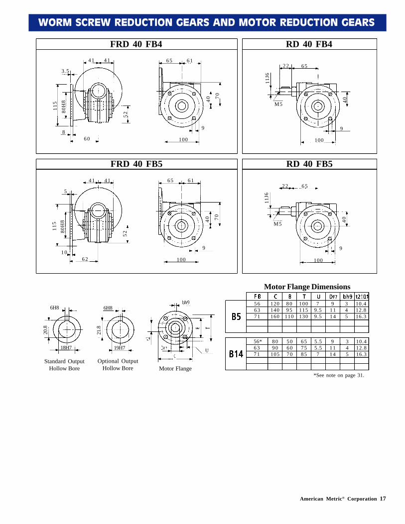
2.4 DIMENSIONS
FRD 30/B (B1)
FRD 30/A (A1)
FRD 30/V (V1)
RD 30/A (A1)
RD 30/B (B1)
RD 30/V (V1)
(27.5)31
(27.5)31
6.56680
7
54 46
31.5 50
52 (55)
52 (50)78
(27.5)31
(27.5)31
6.566
80
7
54 46
31.5
3952 (5
5)
52 (50)78
6.5
(27.5)31
(27.5)31
6.56680
7
31.5
5452 (5
5)
52 (50)78
39 50
20 48
9J6
31.5
52 (55)
52 (50)78
6.5
M4
20 48
9J6
31.5
52 (55)
52 (50)78
6.5M4
9J6M4
31.520
4852 (5
5)
52 (50)78
6.5
5663
120140
8095
100115
79.5
911
34
10.412.8
5663
8090
5060
6575
5.55.5
911
34
10.412.8Motor Flange
5H8
14H7
16.3
Standard OutputHollow Bore
Motor Flange Dimensions
American Metric® Corporation 13
WORM SCREW REDUCTION GEARS AND MOTOR REDUCTION GEARS
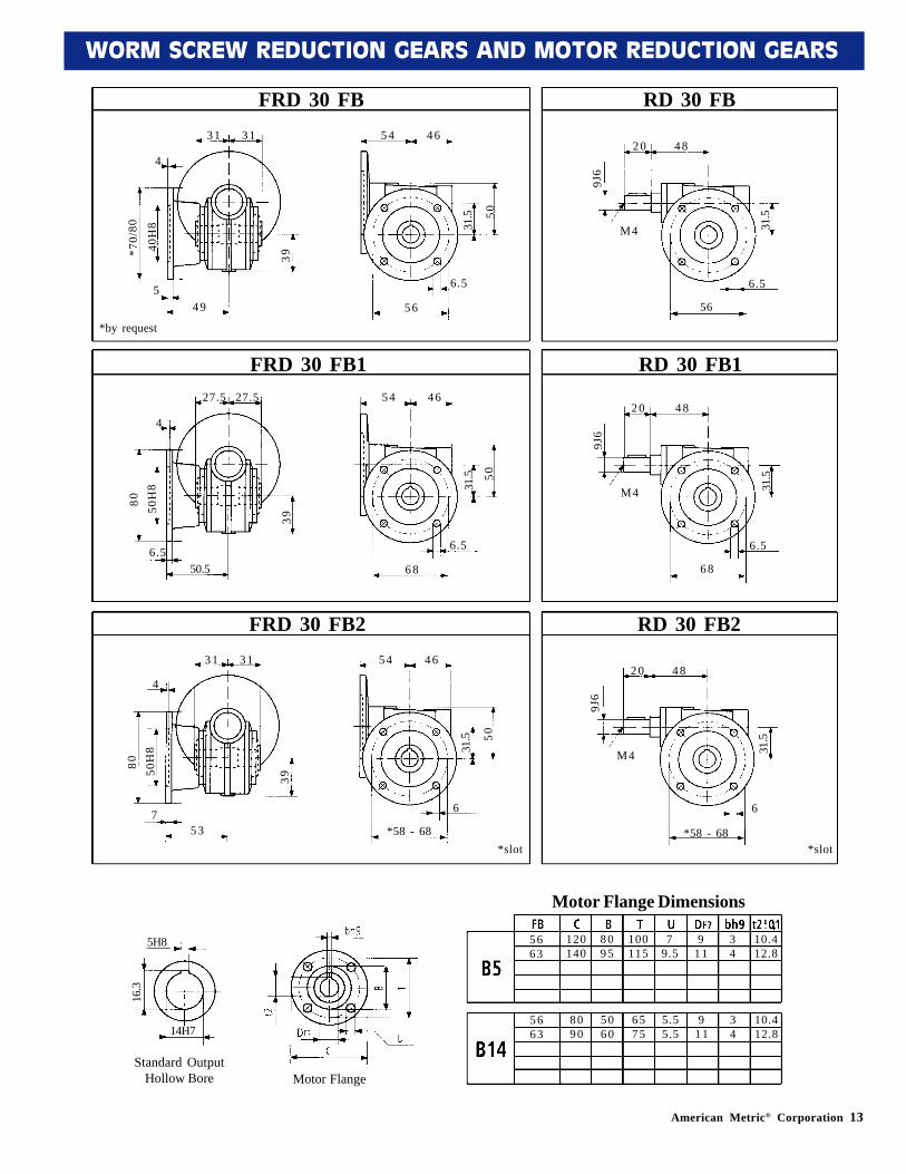
FRD 30 FB1
FRD 30 FB
FRD 30 FB2
RD 30 FB
RD 30 FB1
RD 30 FB2
31 31
549
4
54 46
31.5 50
5 6
6.5
20 48
9J6
31.5
56
6.5
M4
5663
120140
8095
100115
79.5
911
34
10.412.8
5663
8090
5060
6575
5.55.5
911
34
10.412.8
*70/
80
40H
8
39
27.5 27.5
6.550.5
4
54 46
31.5 50
6 8
6.5
20 48
9J6
31.5
6 8
6.5
M4
80 50H
8
39
3 1 31
753
4
54 46
31.5 50
*58 - 68
6
20 48
9J6
31.5
6
M4
80 50H
8
39
*58 - 68*slot *slot
*by request
5H8
14H7
16.3
Motor Flange
5H8
14H7
16.3
Standard OutputHollow Bore
Motor Flange Dimensions
14 American Metric® Corporation
WORM SCREW REDUCTION GEARS AND MOTOR REDUCTION GEARS
FRD 30 FP1
FRD 30 FP RD 30 FP
RD 30 FP1
31 31
2 30.5
54 46
31.5 50
5 6
20 48
9J6
31.5
56
M474*4
2H8
*Option 42H8 (female) Depth 6.5
35M6x8
39
M6x8
27.5 27.5
1.5 60
54 46
31.5 50
6 5
20 48
9J6
31.5
6 5
M4
50H
8
45
M6x739
M6x7
54
1.5
5663
120140
8095
100115
79.5
911
34
10.412.8
5663
8090
5060
6575
5.55.5
911
34
10.412.8
5H8
14H7
16.3
3 6
5H8
14H7
16.3
Motor Flange
5H8
14H7
16.3
Standard OutputHollow Bore
Motor Flange Dimensions
American Metric® Corporation 15
WORM SCREW REDUCTION GEARS AND MOTOR REDUCTION GEARS
FRD 40/B (B1)
FRD 40/A (A1)
FRD 40/V (V1)
RD 40/A (A1)
RD 40/B (B1)
RD 40/V (V1)
(32)41
(32)41
8.584 (81)102
9
65 61
40 70
71 (72)
70 (52)106
(32)41
(32)41
8.584 (81)
102
9
65 61
40
5271 (7
2)
70 (52)106
8.5
(32)41
(32)41
8.584 (81)102
9
40
6571 (7
2)
70 (52)106
52 70
22 65
11J6
4071 (7
2)
70 (52)106
8.5
M5
22 65
11J6
4071 (7
2)
70 (52)106
8.5M5
11J6M5
40 2265
71 (72)
70 (52)106
8.5
566371
120140160
8095
110
100115130
79.59.5
91114
345
10.412.816.3
56*6371
8090
105
506070
657585
5.55.57
91114
345
10.412.816.3
6H8
19H7
21.8
*See note on page 31.
6H8
18H7
20.8
standard
Motor Flange Dimensions
5H8
14H7
16.3
Motor Flange
6H8
19H7
21.8
Optional OutputHollow Bore
6H8
18H7
20.8
Standard OutputHollow Bore
16 American Metric® Corporation
WORM SCREW REDUCTION GEARS AND MOTOR REDUCTION GEARS
FRD 40 FB RD 40 FB
41 41
10
65 61
40
70
115
140
95H
8
8 2
5
529
6522
40
9
115
M5
11J6
FRD 40 FB1 RD 40 FB132 32
8
65 61
4070
8 7
110
60H
8
6 0
5
52
9
6522
40
9
87
M5
11J6
FRD 40 FB2 RD 40 FB241 41
8
65 61
40 70
8 7
115
60H
8
6 0
5
52
9
6522
40
9
87
M5
11J6
FRD 40 FB3 RD 40 FB341 41
17
65 61
40 70
8 7
110
60H
8
6 9
6
52
9
6522
40
9
87
M5
11J6
American Metric® Corporation 17
WORM SCREW REDUCTION GEARS AND MOTOR REDUCTION GEARS
FRD 40 FB4 RD 40 FB441 41
8
65 61
40 70
100
115
80H
8
6 0
3.5
529
6522
40
9
100
M5
11J6
FRD 40 FB5 RD 40 FB541 41
10
65 61
40 70
100
115
80H
8
6 2
5
52
9
6522
40
9
100
M5
11J6
5 66371
120140160
8095
110
100115130
79.59.5
91114
345
10.412.816.3
56*6371
8090
105
506070
657585
5.55.57
91114
345
10.412.816.3
6H8
19H7
21.8
*See note on page 31.
6H8
18H7
20.8
standard
5H8
14H7
16.3
Motor Flange
6H8
19H7
21.8
Optional OutputHollow Bore
6H8
18H7
20.8
Standard OutputHollow Bore
Motor Flange Dimensions
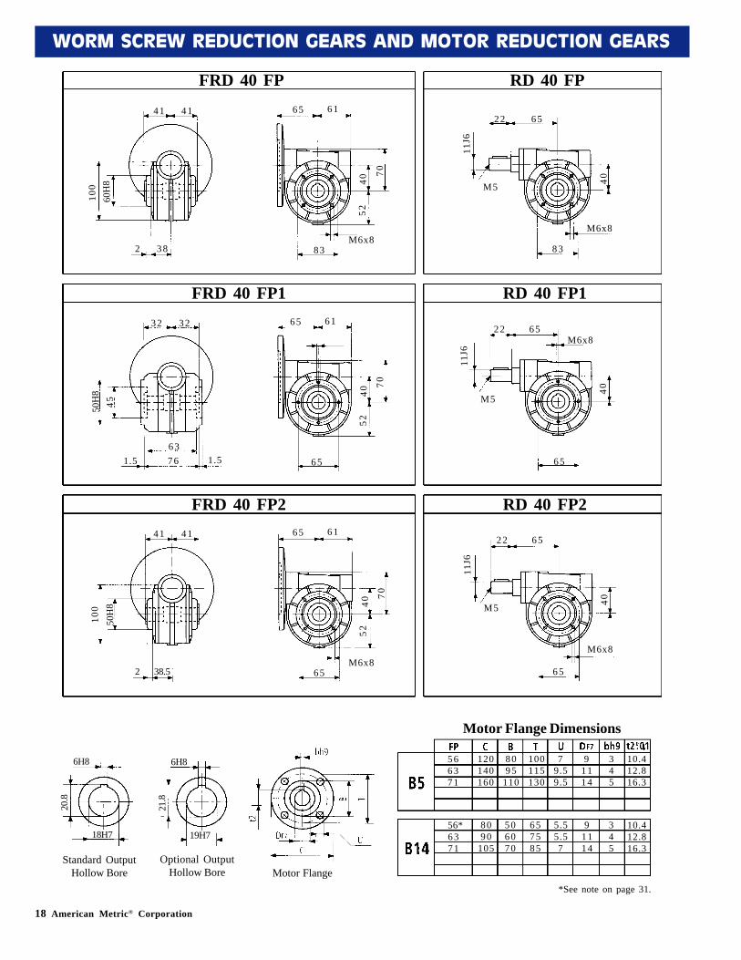
18 American Metric® Corporation
WORM SCREW REDUCTION GEARS AND MOTOR REDUCTION GEARS
FRD 40 FP RD 40 FP
41 41
2 38
65 61
40
70
52
M6x883
22 65
11J6
40
8 3
M5
566371
120140160
8095
110
100115130
79.59.5
91114
345
10.412.816.3
56*6371
8090
105
506070
657585
5.55.57
91114
345
10.412.816.3
6H8
19H7
21.8
*See note on page 31.
6H8
18H7
20.8
standard
60H
810
0
M6x8
FRD 40 FP1 RD 40 FP132 32
1.5 76
65 61
40
70
52
6 5
22 65
11J6
40
6 5
M5
50H
845
FRD 40 FP2 RD 40 FP241 41
2 38.5
65 61
40
70
52
M6x865
22 65
11J6
40
6 5
M5
50H
810
0
M6x8
631.5
M6x8
5H8
14H7
16.3
Motor Flange
6H8
19H7
21.8
Optional OutputHollow Bore
6H8
18H7
20.8
Standard OutputHollow Bore
Motor Flange Dimensions

American Metric® Corporation 19
WORM SCREW REDUCTION GEARS AND MOTOR REDUCTION GEARS
FRD 50/B (B1)
FRD 50/A (A1)
FRD 50/V (V1)
RD 50/A (A1)
RD 50/B (B1)
RD 50/V (V1)
(41)49
(41)49
9*96/99120
12
76 72
50 81
85 (82)
85 (63)125
(41)49
(41)49
9*96/99
120
12
76 72
50
6485 (8
2)
85 (63)125
9
(4149
(41)49
9*96/99120
12
50
7685 (8
2)
85 (63)125
64 81
30 75
14J6
5085 (8
2)
85 (63)125
9
M6
30 75
14J6
5085 (8
2)
85 (63)125
9M6
14J6M6
50 3075
85 (82)
85 (63)125
9
637180
140160200
95110130
115130165
9.59.5
11.5
111419
456
12.816.321.8
63*7180
90105120
607080
7585
100
5.577
111419
456
12.816.321.8
8H8
25H7
28.3
*See note on page 31.
8H8
24H7
27.3
standard
*Slot
*Slot
*Slot
5H8
14H7
16.3
Motor Flange
8H8
24H7
27.3
Optional OutputHollow Bore
8H8
25H7
28.3
Standard OutputHollow Bore
Motor Flange Dimensions
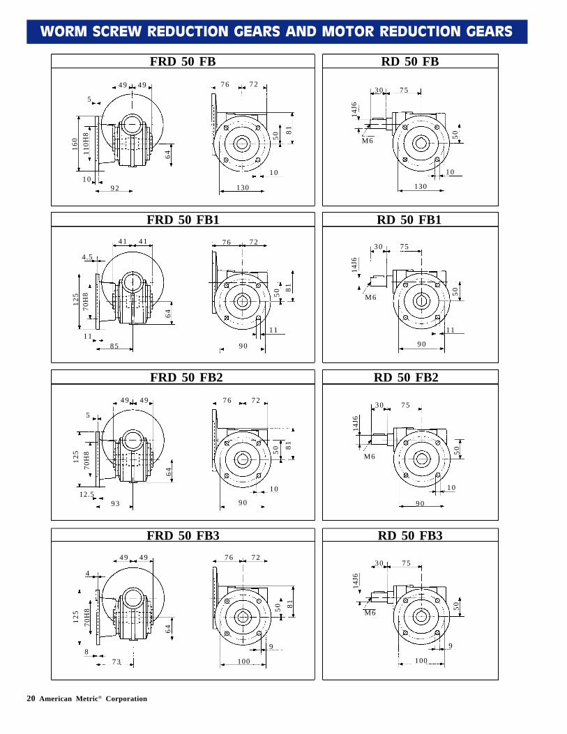
20 American Metric® Corporation
WORM SCREW REDUCTION GEARS AND MOTOR REDUCTION GEARS
FRD 50 FB RD 50 FB
49 49
10
76 72
50
81
130
160
110H
8
9 2
5
641 0
7530
50
1 0
130
M6
14J6
FRD 50 FB1 RD 50 FB141 41
11
76 72
5081
9 0
125
70H
8
8 5
4.5
64
1 1
7530
50
1 1
90
M6
14J6
FRD 50 FB2 RD 50 FB249 49
12.5
76 72
50 81
9 0
125
70H
8
9 3
5
64
1 0
7530
50
1 0
90
M6
14J6
FRD 50 FB3 RD 50 FB349 49
8
76 72
50 81
100
125
70H
8
7 3
4
64
9
7530
50
9
100
M6
14J6
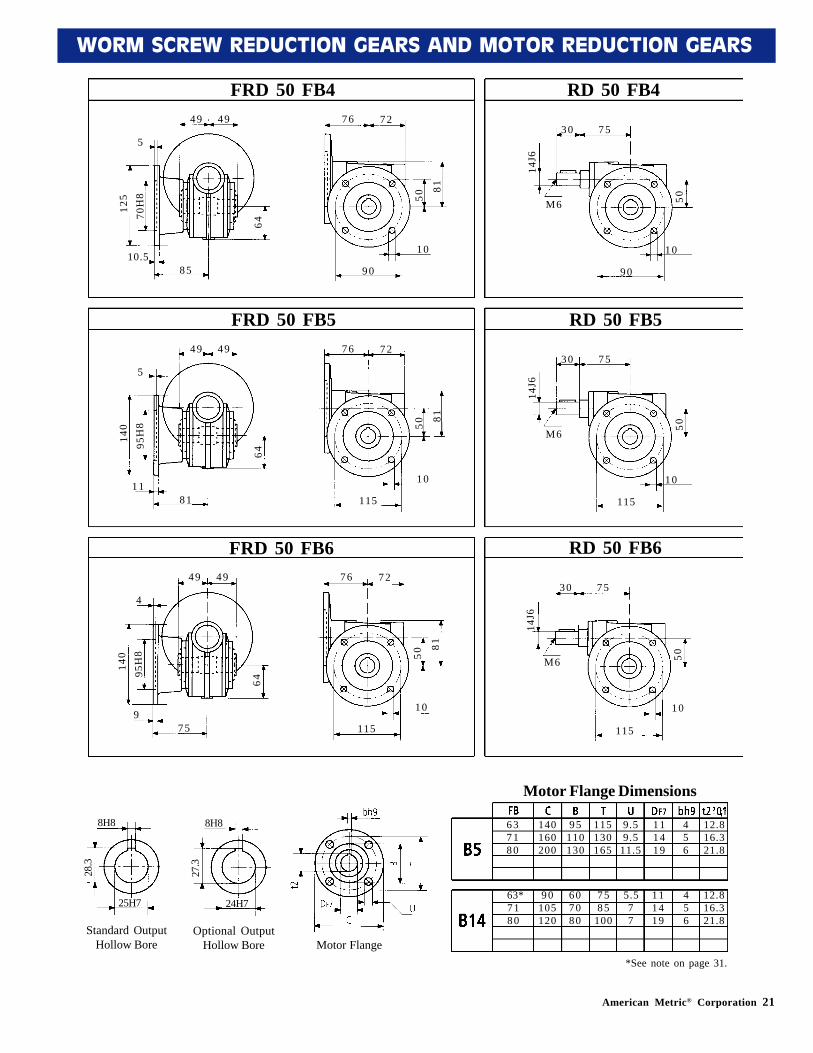
American Metric® Corporation 21
WORM SCREW REDUCTION GEARS AND MOTOR REDUCTION GEARS
FRD 50 FB5
FRD 50 FB4
FRD 50 FB6
RD 50 FB4
RD 50 FB5
RD 50 FB6
49 49
5
8510.5
76 72
50
81
9 0
30 75
14J6
50
9 0
M6
637180
140160200
95110130
115130165
9.59.5
11.5
111419
456
12.816.321.8
63*7180
90105120
607080
7585
100
5.577
111419
456
12.816.321.8
8H8
25H7
28.3
*See note on page 31.
8H8
24H7
27.3
standard
125
70H
8
641 0 10
49 49
5
8111
76 72
50
81
115
30 75
14J6
50
115
M6140
95H
8
64
1 0 10
49 49
4
759
76 72
50
81
115
30 75
14J6
50
115
M6140
95H
8
64
1 0 10
5H8
14H7
16.3
Motor Flange
8H8
24H7
27.3
Optional OutputHollow Bore
8H8
25H7
28.3
Standard OutputHollow Bore
Motor Flange Dimensions
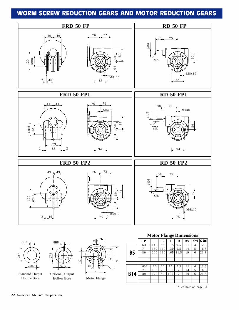
22 American Metric® Corporation
WORM SCREW REDUCTION GEARS AND MOTOR REDUCTION GEARS
FRD 50 FP RD 50 FP49 49
2 46
76 72
5081
64
M8x1085
30 75
14J6
50
8 5
M6
637180
140160200
95110130
115130165
9.59.5
11.5
111419
456
12.816.321.8
63*7180
90105120
607080
7585
100
5.577
111419
456
12.816.321.8
8H8
25H7
28.3
*See note on page 31.
8H8
24H7
27.3
standard
70H
812
0
M8x10
FRD 50 FP1 RD 50 FP141 41
2 88
76 72
50
81
64
9 4
30 75
14J6
50
9 4
M5
68H
860
FRD 50 FP2 RD 50 FP249 49
2 46
76 72
50
81
64
M6x1075
30 75
14J6
50
7 5
M6
60H
812
0
M6x10
792
M6x8M6x8
5H8
14H7
16.3
Motor Flange
8H8
24H7
27.3
Optional OutputHollow Bore
8H8
25H7
28.3
Standard OutputHollow Bore
Motor Flange Dimensions
American Metric® Corporation 23
WORM SCREW REDUCTION GEARS AND MOTOR REDUCTION GEARS
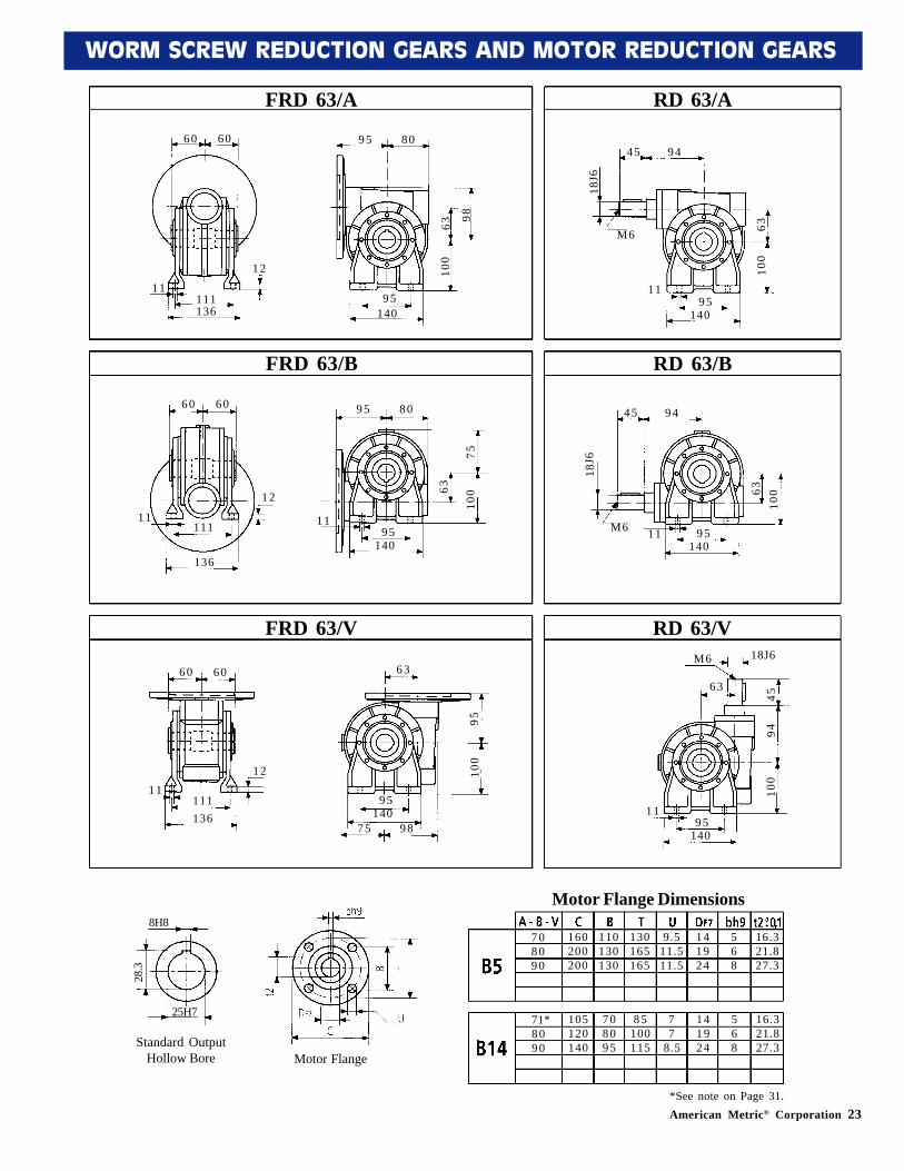
FRD 63/B
FRD 63/A
FRD 63/V
RD 63/A
RD 63/B
RD 63/V
60 60
11111136
12
95 80
63
98
100
9 5140
60 60
11111
136
12
95 80
63
7510
0
9 5140
11
60 60
11111136
12
63
9510
0
9 5140
75 98
45 94
18J6
6310
0
9 5140
11
M6
45 94
18J6
6310
0
9 5140
11M6
18J6M6
63
4594
100
9 5140
11
708090
160200200
110130130
130165165
9.511.511.5
141924
568
16.321.827.3
71*8090
105120140
708095
85100115
77
8.5
141924
568
16.321.827.3
8H8
25H7
28.3
*See note on Page 31.
5H8
14H7
16.3
Motor Flange
8H8
25H7
28.3
Standard OutputHollow Bore
Motor Flange Dimensions
24 American Metric® Corporation
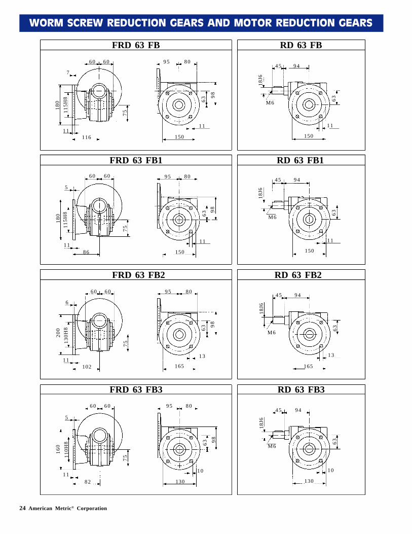
WORM SCREW REDUCTION GEARS AND MOTOR REDUCTION GEARS
FRD 63 FB RD 63 FB60 60
11
95 80
63
98
150
180
115H
8
116
7
751 1
9445
63
1 1
150
M6
18J6
FRD 63 FB1 RD 63 FB160 60
11
95 80
6398
150
180
115H
8
8 6
5
75
1 1
9445
63
1 1
150
M6
18J6
FRD 63 FB2 RD 63 FB260 60
11
95 80
63 98
165
200
130H
8
102
6
75
1 3
9445
63
1 3
165
M6
18J6
FRD 63 FB3 RD 63 FB360 60
11
95 80
63 98
130
160
110H
8
8 2
5
75
1 0
9445
63
1 0
130
M6
18J6
American Metric® Corporation 25
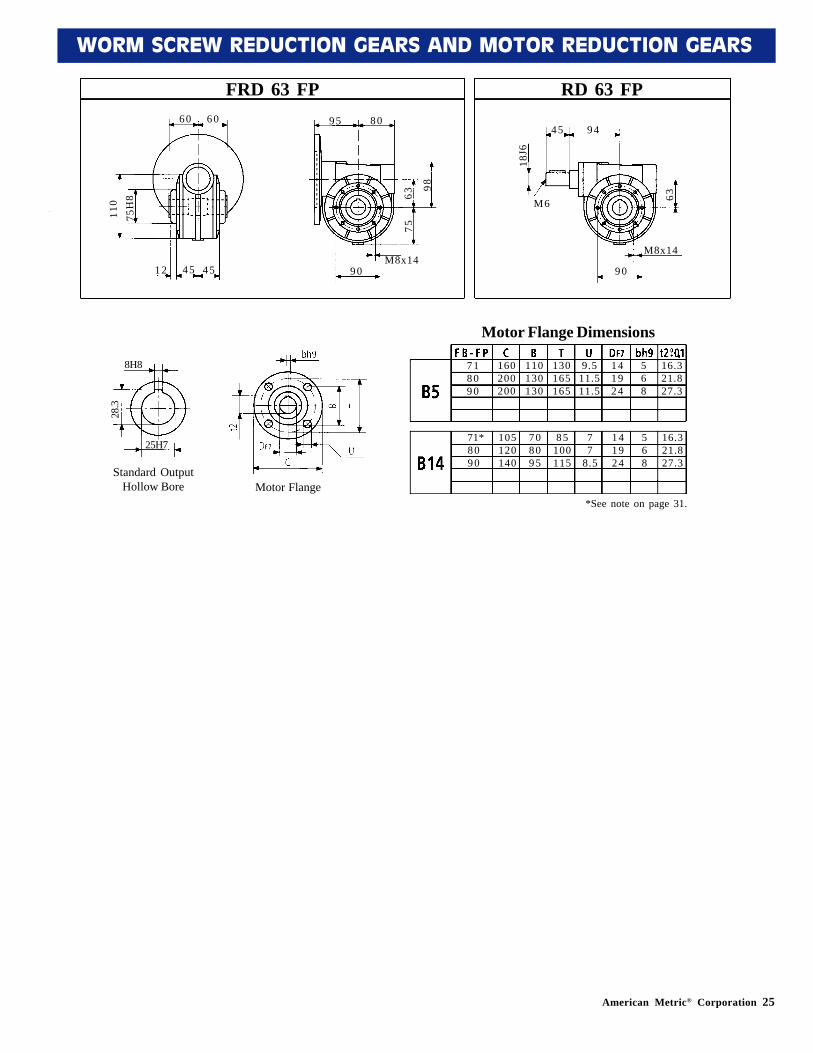
WORM SCREW REDUCTION GEARS AND MOTOR REDUCTION GEARS
FRD 63 FP RD 63 FP60 60
12
95 80
63
98
9 0
110
75H
8
4 5M8x14
9445
63
9 0
M6
18J6
4 5
75
M8x14
718090
160200200
110130130
130165165
9.511.511.5
141924
568
16.321.827.3
71*8090
105120140
708095
85100115
77
8.5
141924
568
16.321.827.3
*See note on page 31.
8H8
25H7
28.3
5H8
14H7
16.3
Motor Flange
8H8
25H7
28.3
Standard OutputHollow Bore
Motor Flange Dimensions
26 American Metric® Corporation
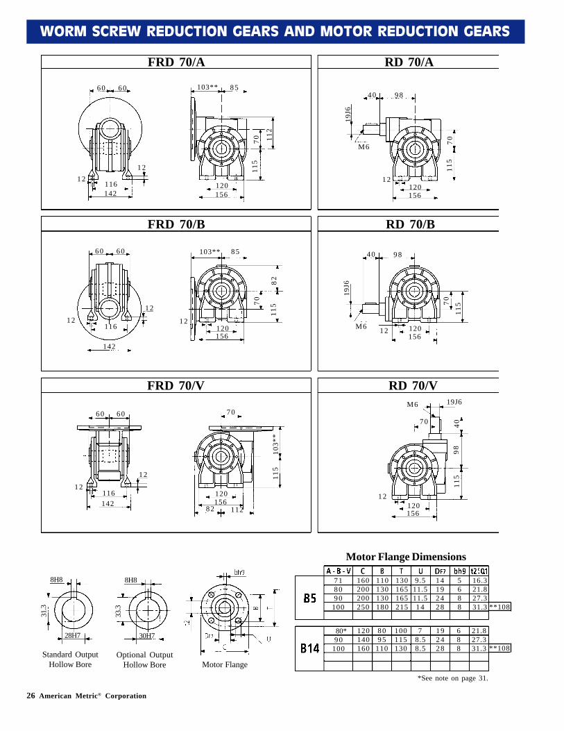
WORM SCREW REDUCTION GEARS AND MOTOR REDUCTION GEARS
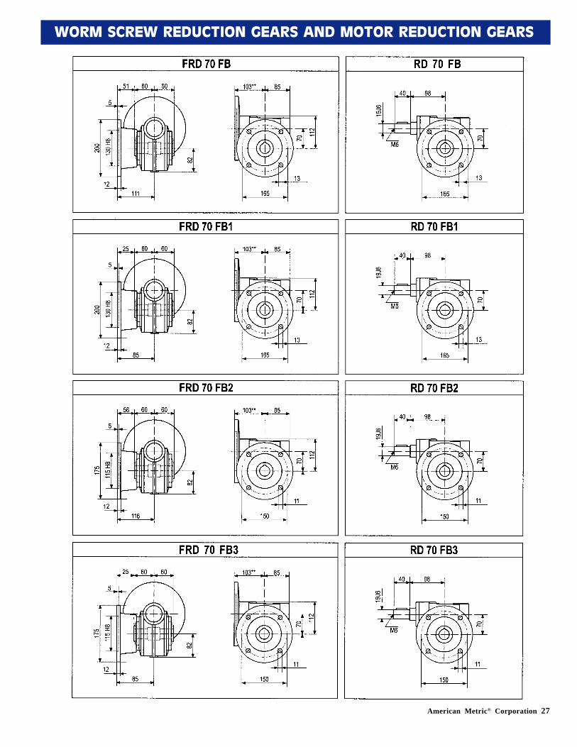
FRD 70/B
FRD 70/A
FRD 70/V
RD 70/A
RD 70/B
RD 70/V
60 60
12116142
12
103** 85
70 112
115
120156
60 60
12116
142
12
103** 8570
8211
5
120156
12
60 60
12116142
12
70
103*
*11
5
120156
82 112
40 98
19J6
7011
5
120156
12
M6
40 98
19J6
70
115
120156
12M6
19J6M6
70 4098
115
120156
12
718090
100
160200200250
110130130180
130165165215
9.511.511.514
14192428
5688
16.321.827.331.3
80*90
100
120140160
8095
110
100115130
78.58.5
192428
688
21.827.331.3
8H8
30H7
33.3
*See note on page 31.
8H8
28H7
31.3
standard
**108
**108
5H8
14H7
16.3
Motor Flange
8H8
30H7
33.3
Optional OutputHollow Bore
8H8
28H7
31.3
Standard OutputHollow Bore
Motor Flange Dimensions
American Metric® Corporation 27
WORM SCREW REDUCTION GEARS AND MOTOR REDUCTION GEARS
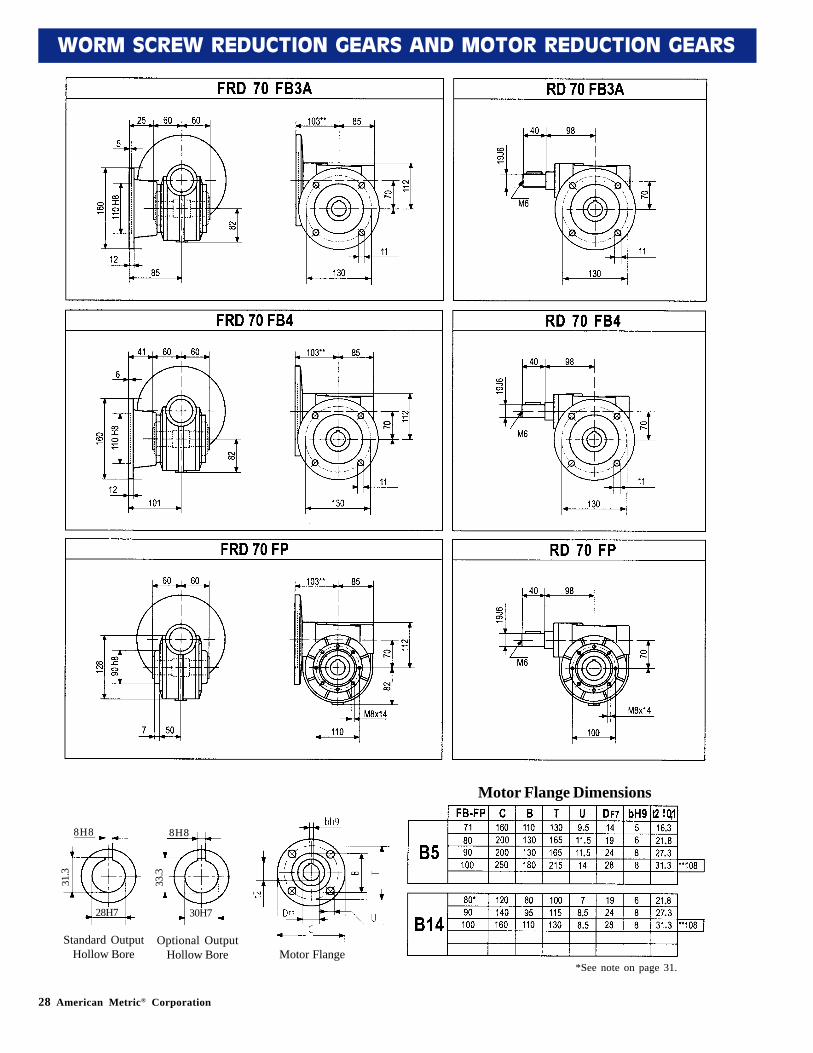
28 American Metric® Corporation
WORM SCREW REDUCTION GEARS AND MOTOR REDUCTION GEARS
10H8
32H7
35.3
35H7
standard
5H8
14H7
16.3
Motor Flange
Motor Flange Dimensions
8H8
28H7
31.3
Standard OutputHollow Bore
8H8
30H7
33.3
Optional OutputHollow Bore
*See note on page 31.
.
.
.
.
.
.
.
.
.
.
..
American Metric® Corporation 29
WORM SCREW REDUCTION GEARS AND MOTOR REDUCTION GEARS
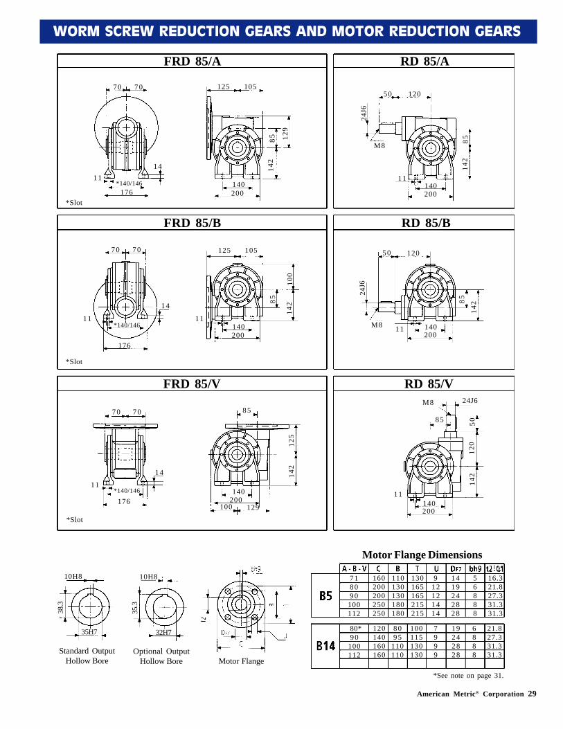
FRD 85/B
FRD 85/A
FRD 85/V
RD 85/A
RD 85/B
RD 85/V
70 70
11*140/146
176
14
125 105
85 129
142
140200
70 70
11*140/146
176
14
125 105
85
100
142
140200
11
70 70
11*140/146
176
14
85
125
142
140200
100 129
50 120
24J6
8514
2
140200
11
M8
50 120
24J6
85
142
140200
11M8
24J6M8
85 5012
014
2
140200
11
718090
100112
160200200250250
110130130180180
130165165215215
912121414
1419242828
56888
16.321.827.331.331.3
80*90
100112
120140160160
8095
110110
100115130130
7999
19242828
6888
21.827.331.331.3
*See note on page 31.
*Slot
*Slot
*Slot
10H8
32H7
35.3
10H8
35H7
38.3
standard
5H8
14H7
16.3
Motor Flange
10H8
32H7
35.3
Optional OutputHollow Bore
10H8
35H7
38.3
Standard OutputHollow Bore
Motor Flange Dimensions
30 American Metric® Corporation
WORM SCREW REDUCTION GEARS AND MOTOR REDUCTION GEARS
.
.
*Slot
*Slot
*Slot *Slot
*Slot
*Slot
**
* *
**
American Metric® Corporation 31
WORM SCREW REDUCTION GEARS AND MOTOR REDUCTION GEARS
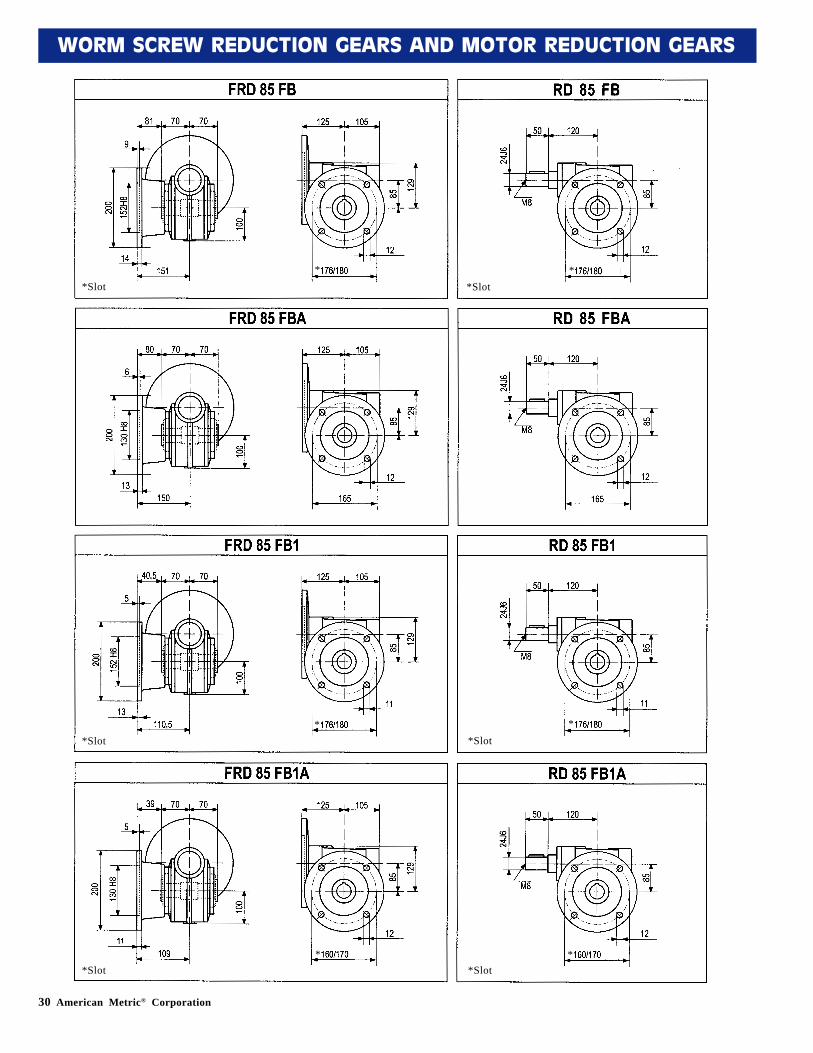
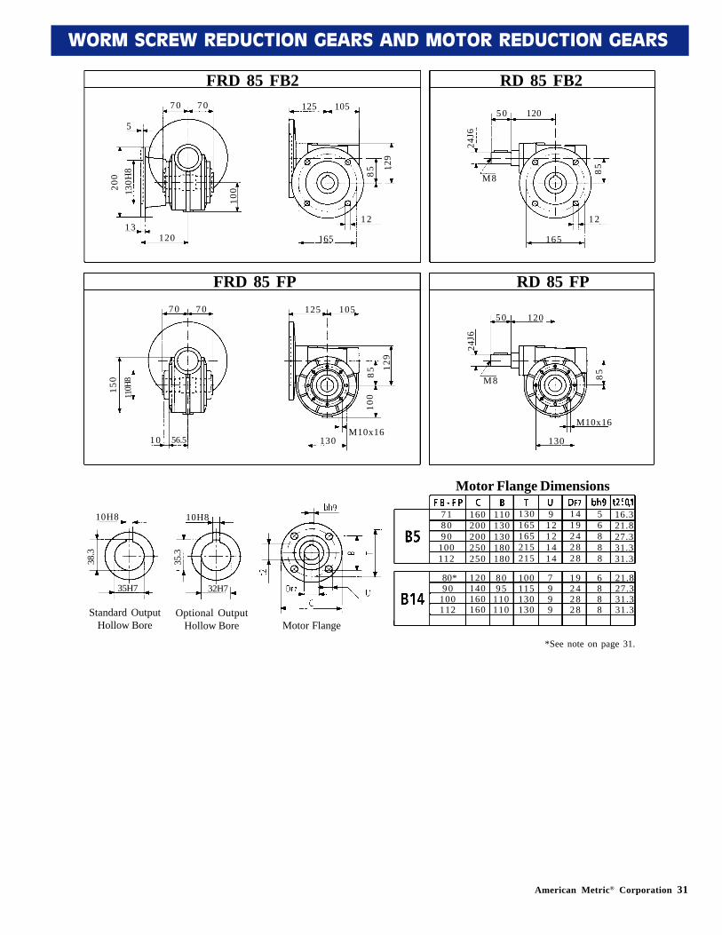
FRD 85 FB2 RD 85 FB2
13
125 105
85
129
165
50 120
24J6
85
165
M8
130H
820
05
12010
01 2 12
FRD 85 FP RD 85 FP70 70
10 56.5
125 105
85
129
100
130
50 120
24J6
85
130
M8
M10x16
110H
815
0
M10x16
718090
100112
160200200250250
110130130180180
130165165215215
912121414
1419242828
56888
16.321.827.331.331.3
80*90
100112
120140160160
8095
110110
100115130130
7999
19242828
6888
21.827.331.331.3
10H8
32H7
35.3
*See note on page 31.
10H8
35H7
38.3
standard
10H8
32H7
Optional OutputHollow Bore
10H8
35H7
38.3
Standard OutputHollow Bore
5H8
14H7
16.3
Motor Flange
Motor Flange Dimensions
35.3
7 0 70
32 American Metric® Corporation
WORM SCREW REDUCTION GEARS AND MOTOR REDUCTION GEARS
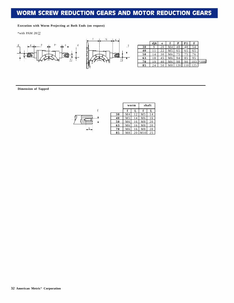
Execution with Worm Projecting at Both Ends (on request)
*with PAM 28/250160
Dimension of Tapped
91114181924
202230454050
M4M5M6M6M6M8
4865759498
120
4865758590
110
54657695
103125
*108
dj6 e f P P1 F304050637085
304050637085
f fL LM4M5M6M6M6M8
M5M6M8M8M8
M10
121416161620
141620202025
worm shaft
American Metric® Corporation 33
WORM SCREW REDUCTION GEARS AND MOTOR REDUCTION GEARS
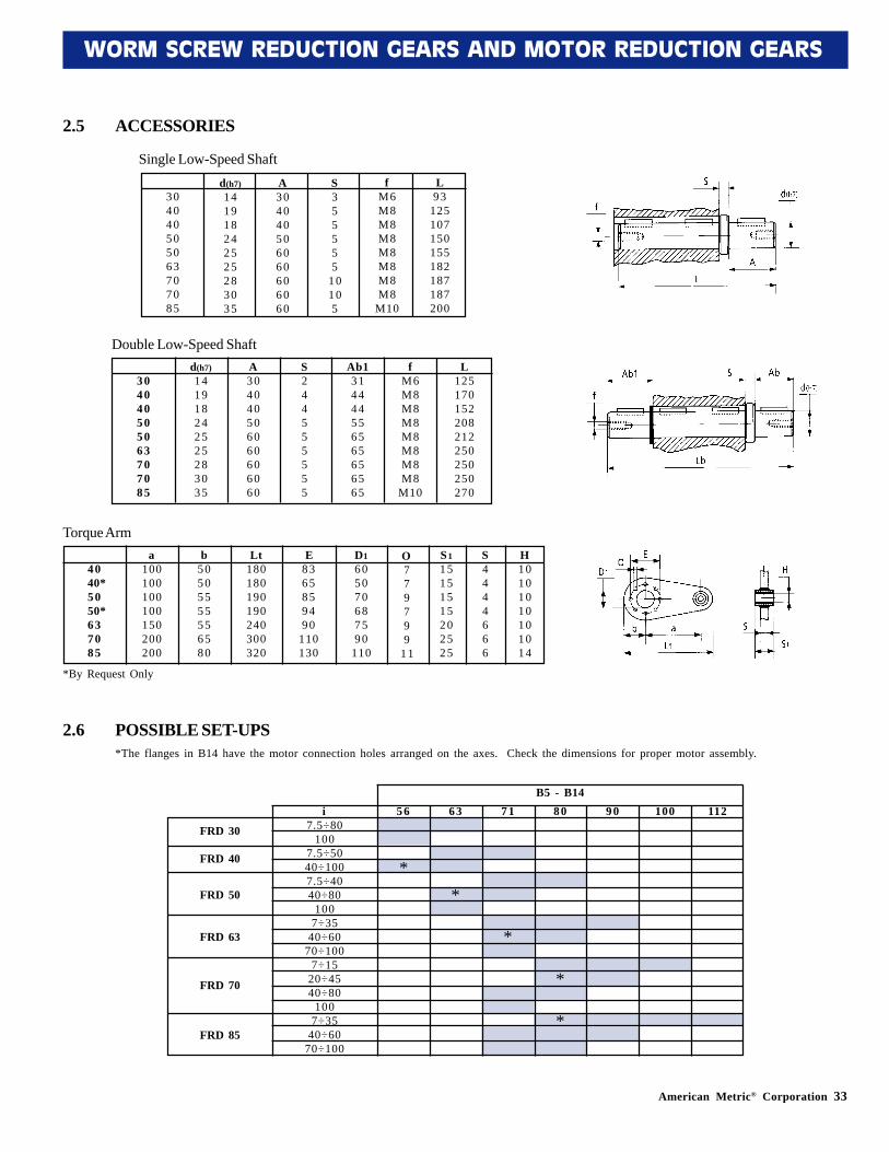
2.5 ACCESSORIES
d(h7)141918242525283035
A304040506060606060
S355555
10105
fM6M8M8M8M8M8M8M8
M10
L93
125107150155182187187200
304040505063707085
d(h7)141918242525283035
A304040506060606060
S244555555
fM6M8M8M8M8M8M8M8
M10
L125170152208212250250250270
304040505063707085
Ab1314444556565656565
a100100100100150200200
b50505555556580
Lt180180190190240300320
D1605070687590
110
O779799
11
40 40*50
50*637085
E8365859490
110130
S115151515202525
S4444666
H10101010101014
2.6 POSSIBLE SET-UPS
i7.5÷80
1007.5÷5040÷1007.5÷4040÷80
1007÷35
40÷6070÷100
7÷1520÷4540÷80
1007÷35
40÷6070÷100
Single Low-Speed Shaft
Double Low-Speed Shaft
Torque Arm
*By Request Only
*The flanges in B14 have the motor connection holes arranged on the axes. Check the dimensions for proper motor assembly.
FRD 30
FRD 40
FRD 50
FRD 63
FRD 70
FRD 85
56 63 71 80 90 100 112
*
*
*
**
B5 - B14
34 American Metric® Corporation
WORM SCREW REDUCTION GEARS AND MOTOR REDUCTION GEARS
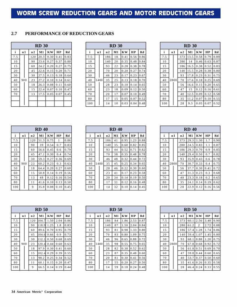
2.7 PERFORMANCE OF REDUCTION GEARS
RD 30 RD 30 RD 30i
7.51015203040506070
n 1
900
n 21209060453023181513
M120.323.624.222.627.527.226.322.417.5
KW0.300.270.200.150.130.100.080.070.05
HP0.410.370.270.200.180.140.110.100.07
Rd0.830.800.750.710.640.610.600.470.45
n 2186140937046352823201714
M11820222023252318171510
KW0.410.350.280.200.170.130.100.090.070.050.03
HP0.560.480.380.270.230.180.140.120.100.070.04
Rd0.860.840.780.740.670.700.650.500.490.520.48
n 237328018614093705647403528
M113.514
16.515.517.817.616.615
12.511.29.3
KW0.580.460.380.280.230.180.150.120.090.070.05
HP0.790.630.520.380.310.250.200.160.120.100.07
Rd0.890.870.830.800.750.690.650.610.580.550.52
i7.5101520304050607080
100
i7.5101520304050607080
100
n 1
1400
n 1
2800
RD 40 RD 40 RD 40i
7.5101520304050607080
100
n 1
900
n 21209060453023181513119
M151.339
56.647.159.360.264.450.848
41.635.8
KW0.750.540.450.300.270.230.200.140.120.100.08
HP1
0.70.60.4
0.360.3
0.270.190.160.130.10
Rd0.860.830.790.740.690.630.600.560.540.500.45
n 2186140937046352823201714
M14135443848454641343132
KW0.950.600.520.350.320.250.220.170.140.120.10
HP1.230.820.710.480.440.340.300.230.190.160.14
Rd0.880.850.820.780.720.650.600.580.500.480.45
n 237328018614093705647403528
M129.324.529.329.435.930.737.731.323.324.122.9
KW1.300.830.700.500.430.330.300.230.180.140.12
HP1.71.10.90.70.60.4
0.410.30.2
0.190.16
Rd0.900.870.850.820.780.750.720.680.650.620.56
i7.5101520304050607080
100
i7.5101520304050607080
100
n 1
1400
n 1
2800
RD 50 RD 50 RD 50i
7.5101520304050607080
100
n 1
900
n 21209060453023181513119
M1104.7118.989.6
104.6112.1120.497.9
102.498.260.166.5
KW1.501.250.700.660.500.440.300.290.250.150.14
HP2.041.8
0.950.9
0.680.600.410.390.340.200.19
Rd0.860.830.790.730.690.630.600.550.520.470.44
n 2186140937046352823201714
M18487818396988287815559
KW1.861.500.980.800.650.550.380.350.300.200.18
HP2.532.041.331.090.880.750.520.480.410.270.24
Rd0.870.840.800.750.720.650.620.600.560.500.48
n 237328018614093705647403528
M160.161.257.459.468.167.861.859.853.741.646.4
KW2.56
21.281.070.880.680.510.440.370.260.24
HP3.482.721.741.451.200.920.690.600.500.350.33
Rd0.900.880.860.800.750.720.700.650.600.580.55
i7.5101520304050607080
100
i7.5101520304050607080
100
n 1
1400
n 1
2800
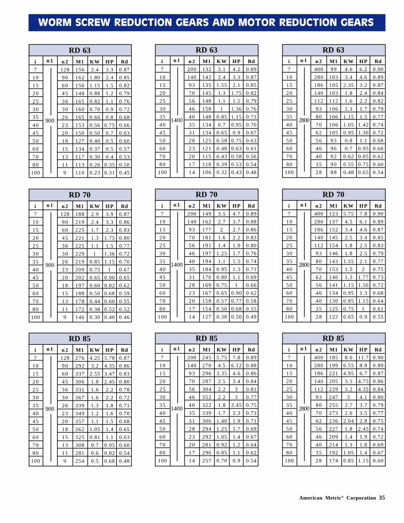
American Metric® Corporation 35
WORM SCREW REDUCTION GEARS AND MOTOR REDUCTION GEARS
RD 63i7
101520253035404550607080
100
n 1 n 21289060453630262320181513119
M1156162150148165160165153150127134117113110
KW2.4
1.801.150.880.820.700.660.560.500.400.370.300.260.23
HP3.32.41.51.21.10.90.8
0.750.70.50.50.4
0.350.31
Rd0.870.850.820.790.760.720.680.660.630.600.570.530.500.45
900
RD 63i7
101520253035404550607080
100
n 1 n 2200140937056464035312823201714
M1132142135145148158148134134125121115118106
KW3.12.4
1.551.31.11
0.850.7
0.650.580.480.430.390.32
HP4.23.32.1
1.751.5
1.361.150.950.9
0.750.630.580.530.43
Rd0.890.870.850.820.790.760.730.700.670.630.610.560.540.48
1400
RD 63i7
101520253035404550607080
100
n 1 n 2400280186140112938070625646403528
M199
1031051031121061061061059396929088
KW4.63.4
2.351.81.61.3
1.151.050.950.80.7
0.620.550.48
HP6.24.63.22.42.21.71.5
1.421.301.1
0.950.850.750.65
Rd0.900.890.870.840.820.790.770.740.720.680.660.620.600.54
2800
RD 70i7
101520253035404550607080
100
n 1 n 21289060453630262320181513119
M1188219225221225229219209202197188178172146
KW2.92.41.71.31.11
0.850.750.650.600.500.440.380.30
HP3.93.32.3
1.751.5
1.361.15
10.900.820.680.600.520.40
Rd0.870.860.830.800.770.720.700.670.650.620.590.550.520.46
900
RD 70i7
101520253035404550607080
100
n 1 n 2200140937056464035312823201714
M1149162177181191197194184170169167158154127
KW3.52.72
1.61.4
1.251.1
0.950.800.750.650.570.500.38
HP4.73.72.72.21.91.71.51.31.11
0.900.770.680.50
Rd0.890.880.860.830.800.760.740.710.690.660.620.580.550.49
1400
RD 70i7
101520253035404550607080
100
n 1 n 2400280186140112938070625646403528
M1123137152145154146143153146141134130125122
KW5.754.53.42.51.81.8
1.551.51.3
1.150.950.850.750.65
HP7.86.14.63.42.52.52.12
1.771.561.3
1.151
0.9
Rd0.900.890.870.850.830.790.770.750.730.720.680.640.610.55
2800
RD 85i7
101520253035404550607080
100
n 1 n 21289060453630262320181513119
M1276292337306331367339349357362325308281254
KW4.253.2
2.551.81.61.61.31.21.1
1.050.810.70.60.5
HP5.784.353.472.452.22.21.81.61.51.41.1
0.950.820.68
Rd0.870.860.830.800.780.720.710.700.680.650.630.600.540.48
900
RD 85i7
101520253035404550607080
100
n 1 n 2200140937056464035312823201714
M1245270296287304352322339306294292281296257
KW5.754.5
3.352.52.22.21.81.7
1.401.251.050.920.850.70
HP7.8
6.124.63.433
2.452.31.91.71.41.21.10.9
Rd0.890.880.860.840.810.770.750.730.710.690.670.640.620.54
1400
RD 85i7
101520253035404550607080
100
n 1 n 2400280186140112938070625646403528
M1185199221205229247255273236227209214192174
KW8.6
6.554.953.53.23
2.72.6
2.041.81.41.3
1.050.85
HP11.78.96.7
4.754.354.13.73.52.8
2.451.91.81.4
1.15
Rd0.900.890.870.860.840.800.790.770.750.740.720.690.670.60
2800
36 American Metric® Corporation
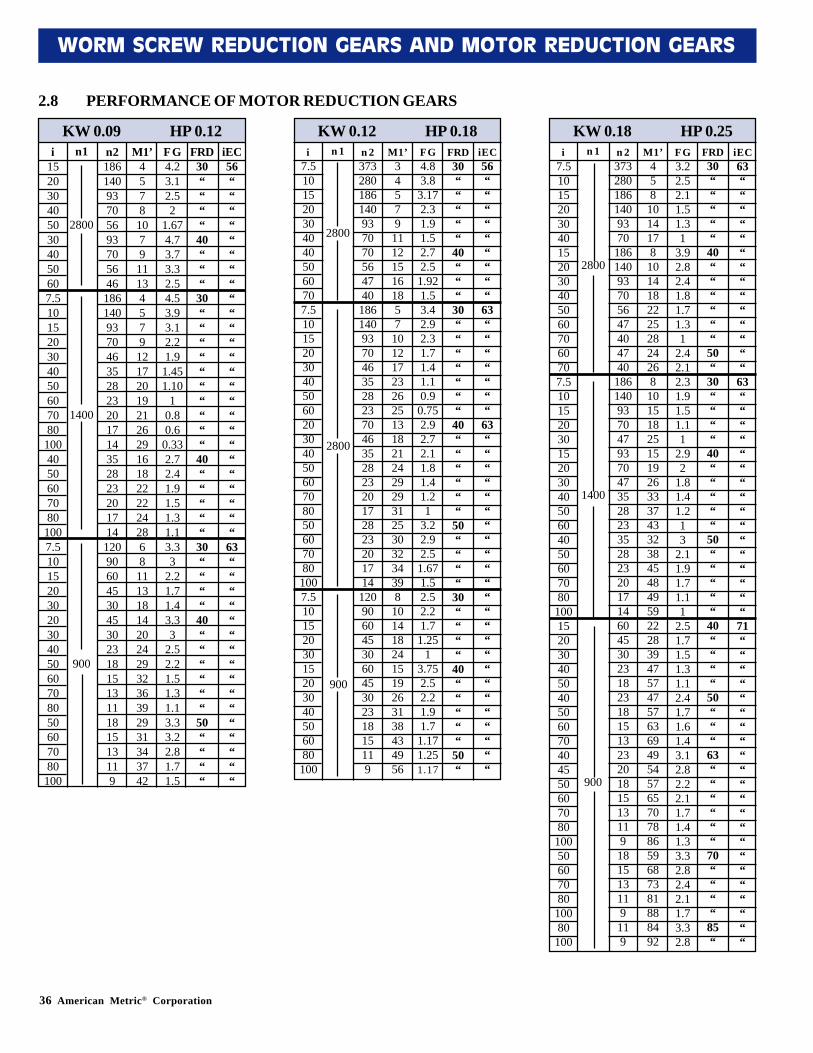
WORM SCREW REDUCTION GEARS AND MOTOR REDUCTION GEARS
2.8 PERFORMANCE OF MOTOR REDUCTION GEARS
KW 0.09 HP 0.12i
1520304050304050607.5101520304050607080
1004050607080
1007.5101520302030405060708050607080
100
n1
2800
1400
900
n2186140937056937056461861409370463528232017143528232017141209060453045302318151311181513119
M1’4578
1079
11134579
1217201921262916182222242868
111318142024293236392931343742
FG4.23.12.52
1.674.73.73.32.54.53.93.12.21.9
1.451.10
10.80.6
0.332.72.41.91.51.31.13.33
2.21.71.43.33
2.52.21.51.31.13.33.22.81.71.5
FRD30““““
40“““
30““““““““““
40“““““
30““““
40““““““
50““““
iEC56“““““““““““““““““““““““““
63““““““““““““““““
KW 0.12 HP 0.18i
7.51015203040405060707.51015203040506020304050607080506070801007.51015203015203040506080100
n 1 n 2373280186140937070564740
186140937046352823704635282320172823201714
12090604530604530231815119
M1’34579
111215161857
1012172326251318212429293125303234398
101418241519263138434956
FG4.83.8
3.172.31.91.52.72.5
1.921.53.42.92.31.71.41.10.9
0.752.92.72.11.81.41.21
3.22.92.5
1.671.52.52.21.7
1.251
3.752.52.21.91.7
1.171.251.17
FRD30“““““
40“““
30“““““““
40““““““
50““““
30““““
40“““““
50“
iEC56“““““““““
63“““““““
63““““““““““““““““““““““““
KW 0.18 HP 0.25n 1
2800
1400
900
n 23732801861409370
18614093705647404740
1861409370479370473528233528232017146045302318231815132320181513119181513119119
M1’458
1014178
10141822252824268
101518251519263337433238454849592228394757475763694954576570788659687381888492
FG3.22.52.11.51.31
3.92.82.41.81.71.31
2.42.12.31.91.51.11
2.92
1.81.41.213
2.11.91.71.11
2.51.71.51.31.12.41.71.61.43.12.82.22.11.71.41.33.32.82.42.11.73.32.8
FRD30“““““
40““““““
50“
30““““
40“““““
50“““““
40““““
50“““
63““““““
70““““
85“
iEC63““““““““““““““
63““““““““““““““““
71““““““““““““““““““““““
i7.510152030401520304050607060707.5101520301520304050604050607080
100152030405040506070404550607080
10050607080
10080
100
2800
2800
900
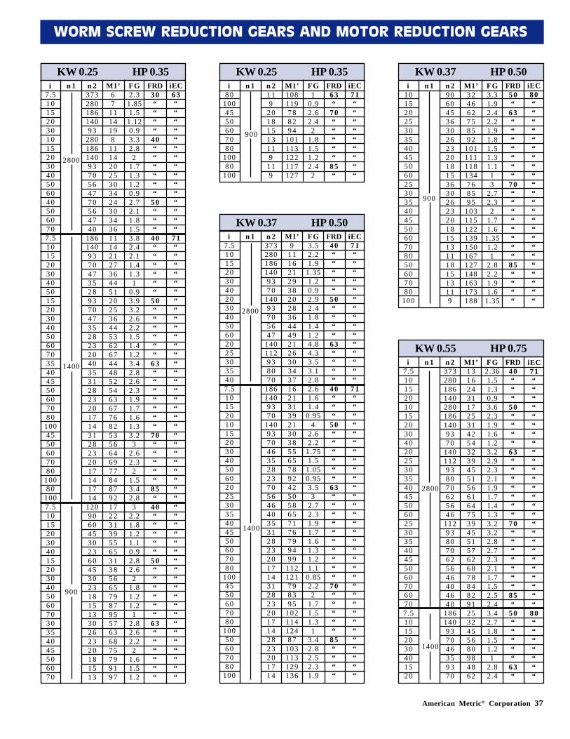
American Metric® Corporation 37
WORM SCREW REDUCTION GEARS AND MOTOR REDUCTION GEARS
KW 0.25 HP 0.35n 1 n 2
37328018614093
2801861409370564770564740
18614093704735289370473528232040353128232017143128232017141714
12090604530236045302318151330262320181513
M1’67
1114198
111420253034243034361114212736445120253644536267444852546367768253566469778487921722313955653138566579879557636875799197
FG2.3
1.851.5
1.120.93.32.82
1.71.31.20.92.72.11.81.53.82.42.11.41.31
0.93.93.22.62.21.51.41.23.42.82.62.31.91.71.61.33.23
2.62.32
1.53.42.83
2.21.81.21.10.92.82.62
1.81.21.21
2.82.62.22
1.61.51.2
FRD30““““
40““““““
50“““
40““““““
50““““““
63“““““““
70“““““
85“
40“““““
50““““““
63““““““
iEC63“““““““““““““““
71“““““““““““““““““““““““““““““““““““““““““““““““““
i7.51015203010152030405060405060707.51015203040501520304050607035404550607080
1004550607080
10080
1007.510152030401520304050607030354045506070
2800
1400
900
KW 0.25 HP 0.35n 1 n 2
119
20181513119
119
M1’108119788294
101113122117127
FG1
0.92.62.42
1.81.51.22.42
FRD63“
70“““““
85“
iEC71“““““““““
i80
1004550607080
10080
100
900
KW 0.37 HP 0.50n 1 n 2
3732801861409370
14093705647
140112938070
1861409370
14093704635282370564640353128232017143128232017142823201714
M1’9
1116212938202836444921263034371621313921303855657892425058657176799499
112121798395
10211412487
103113129136
FG3.52.21.9
1.351.20.92.92.41.81.41.24.84.33.53.12.82.61.61.4
0.954
2.62.2
1.751.5
1.050.953.53
2.72.31.91.71.61.31.21.1
0.852.22
1.71.51.31
3.42.82.52.31.9
FRD40“““““
50““““
63““““
40“““
50““““““
63““““““““““
70“““““
85““““
iEC71“““““““““““““““
71““““““““““““““““““““““““““““““““
i7.51015203040203040506020253035407.51015201015203040506020253035404550607080
1004550607080
10050607080
100
2800
1400
KW 0.37 HP 0.50n 1 n 2
90604536302623201815363026232018151311181513119
M1’324662758592
101111118134768595
103115122139150167127148163173188
FG3.31.92.42.21.91.81.51.31.113
2.72.32
1.71.6
1.351.21
2.82.21.91.6
1.35
FRD50“
63“““““““
70““““““““
85““““
iEC80“““““““““““““““““““““““
i1015202530354045506025303540455060708050607080
100
900
KW 0.55 HP 0.75n 1 n 2
3732801861402801861409370
140112938070625646
112938070625646404640
186140937046359370
M1’1316243117253142543239455156616475394551576268788482912532455680984862
FG2.361.51.30.93.62.31.91.61.23.22.92.32.11.91.71.41.33.23.22.82.72.32.11.71.52.52.43.42.71.81.51.21
2.82.4
FRD40“““
50““““
63“““““““
70“““““““
85“
50“““““
63“
iEC71““““““““““““““““““““““““““
80“““““““
i7.510152010152030402025303540455060253035404550607060707.510152030401520
2800
1400
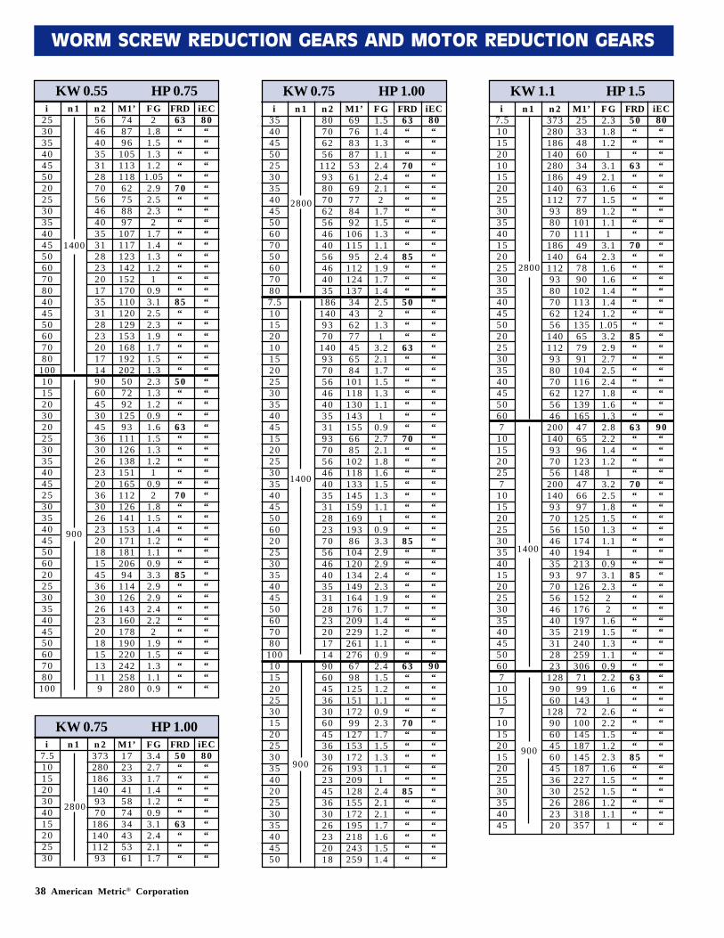
38 American Metric® Corporation
WORM SCREW REDUCTION GEARS AND MOTOR REDUCTION GEARS
KW 0.55 HP 0.75n 1 n 2
56464035312870564640353128232017353128232017149060453045363026232036302623201815453630262320181513119
M1’748796
10511311862758897
107117123142152170110120129153168192202507292
12593
11112613815116511212614115317118120694
114126143160178190220242258280
FG2
1.81.51.31.2
1.052.92.52.32
1.71.41.31.21
0.93.12.52.31.91.71.51.32.31.31.20.91.61.51.31.21
0.92
1.81.51.41.21.10.93.32.92.92.42.22
1.91.51.31.10.9
FRD63“““““
70“““““““““
85““““““
50“““
63“““““
70““““““
85““““““““““
iEC80““““““““““““““““““““““““““““““““““““““““““““““““““
i25303540455020253035404550607080404550607080
100101520302025303540452530354045506020253035404550607080
100
1400
900
KW 0.75 HP 1.00n 1 n 2
3732801861409370
18614011293
M1’17233341587434435361
FG3.42.71.71.41.20.93.12.42.11.7
FRD50“““““
63“““
iEC80“““““““““
i7.5101520304015202530
2800
KW 0.75 HP 1.00n 1 n 2
80706256
1129380706256464056464035
1861409370
140937056464035319370564640353128237056464035312823201714906045363060453630262345363026232018
M1’69768387536169778492
10611595
11212413734436277456584
1011181301431556685
10211813314515916919386
1041201341491641762092292612766798
12515117299
127153172193209128155172195218243259
FG1.51.41.31.12.42.42.12
1.71.51.31.12.41.91.71.42.52
1.31
3.22.11.71.51.31.11
0.92.72.11.81.61.51.31.11
0.93.32.92.92.42.31.91.71.41.21.10.92.41.51.21.10.92.31.71.51.31.11
2.42.12.11.71.61.51.4
FRD63“““
70“““““““
85“““
50“““
63“““““““
70““““““““
85““““““““““
63““““
70“““““
85““““““
iEC80“““““““““““““““““““““““““““““““““““““““““““““““
90“““““““““““““““““
i354045502530354045506070506070807.5101520101520253035404515202530354045506020253035404550607080
100101520253015202530354020253035404550
2800
1400
900
KW 1.1 HP 1.5n 1 n 2
373280186140280186140112938070
1861401129380706256
140112938070625646
200140937056
200140937056464035937056464035312823
1289060
12890604560453630262320
M1’253348603449637789
10111149647890
102113124135657991
104116127139165476596
123148476697
12515017419421397
1261521761972192402593067199
14372
100145187145187227252286318357
FG2.31.81.21
3.12.11.61.51.21.11
3.12.31.61.61.41.41.2
1.053.22.92.72.52.41.81.61.32.82.21.41.21
3.22.51.81.51.31.11
0.93.12.322
1.61.51.31.10.92.21.61
2.62.21.51.22.31.61.51.51.21.11
FRD50“““
63““““““
70“““““““
85“““““““
63““““
70“““““““
85““““““““
63““““““
85““““““
iEC80““““““““““““““““““““““““““
90“““““““““““““““““““““““““““““““““““
i7.510152010152025303540152025303540455020253035404550607
101520257
101520253035401520253035404550607
10157
10152015202530354045
2800
1400
900
American Metric® Corporation 39
WORM SCREW REDUCTION GEARS AND MOTOR REDUCTION GEARS
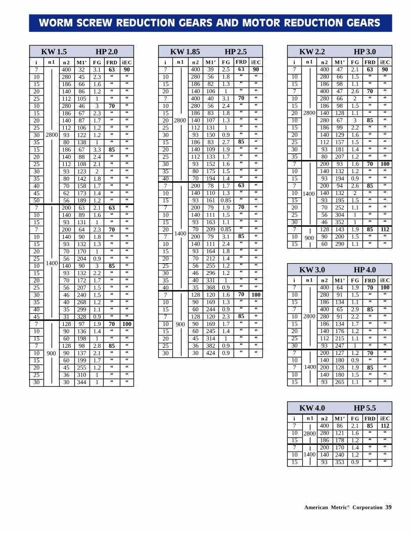
KW 1.5 HP 2.0i71015202510152025303515202530354045507101571015202510152025303540457101571015202530
n 1 n 240028018614011228018614011293801861401129380706256200140932001409370561409370564640353112890601289060453630
M1’32456686
105466787
1061221386788
1081231421581731896389
1316490
13217020490
13217220724026829932897
13619898
137199255310344
FG3.12.31.61.213
2.31.71.21.21
3.32.42.12
1.81.71.41.22.11.61
2.31.81.31
0.93
2.21.71.51.51.21.10.91.91.41
2.82.11.71.211
FRD63““““
70“““““
85“““““““
63““
70““““
85“““““““
70““
85“““““
iEC90““““““““““““““““““““““““““““““““““
100““““““““
KW 1.85 HP 2.5i7101520710152025301520253035407101571015207101520253035407101571015202530
n 1 n 240028018614040028018614011293
186140112938070
20014093
2001409370
200140937056464035
1289060
1289060453630
M1’39568210640568310713115083109133152175194781101617911116320979111164212255296331368120169244120169245314382424
FG2.51.81.31
3.12.41.81.31
0.92.71.91.71.61.51.41.71.30.851.91.51.10.853.12.41.81.41.21.21
0.91.61.30.92.31.71.41
0.90.9
FRD63“““
70“““““
85“““““
63““
70“““
85“““““““
70““
85“““““
iEC90““““““““““““““““““““““““““““““
100““““““““
KW 2.2 HP 3.0n 2400280186400280186140280186140112938020014093200140937056461289060
M1’476698476698
1286799
12915718120793
13219494
132195252304352143200290
FG2.11.51.12.62
1.51.13
2.21.61.51.41.21.61.20.92.62
1.51.111
1.91.51.1
FRD63““
70“““
85“““““
70““
85“““““
85““
iEC90““““““““““““
100““““““““
112““
i7
10157
1015201015202530357
10157
10152025307
1015
2800
1400
900
2800
1400
900
2800
1400
900
KW 3.0 HP 4.0n 24002801864002801861401129320014020014093
M1’6491
1346591
134176215247127180128180265
FG1.91.51.12.92.21.71.21.11
1.20.91.91.51.1
FRD70““
85“““““
70“
85““
iEC100“““““““““““““
i7
10157
10152025307
107
1015
2800
1400
KW 4.0 HP 5.5n 240028018620014093
M1’86
121178170240353
FG2.11.61.21.41.20.9
FRD85“““““
iEC112“““““
i7
10157
1015
2800
1400
n 1
n 1
n 1
40 American Metric® Corporation
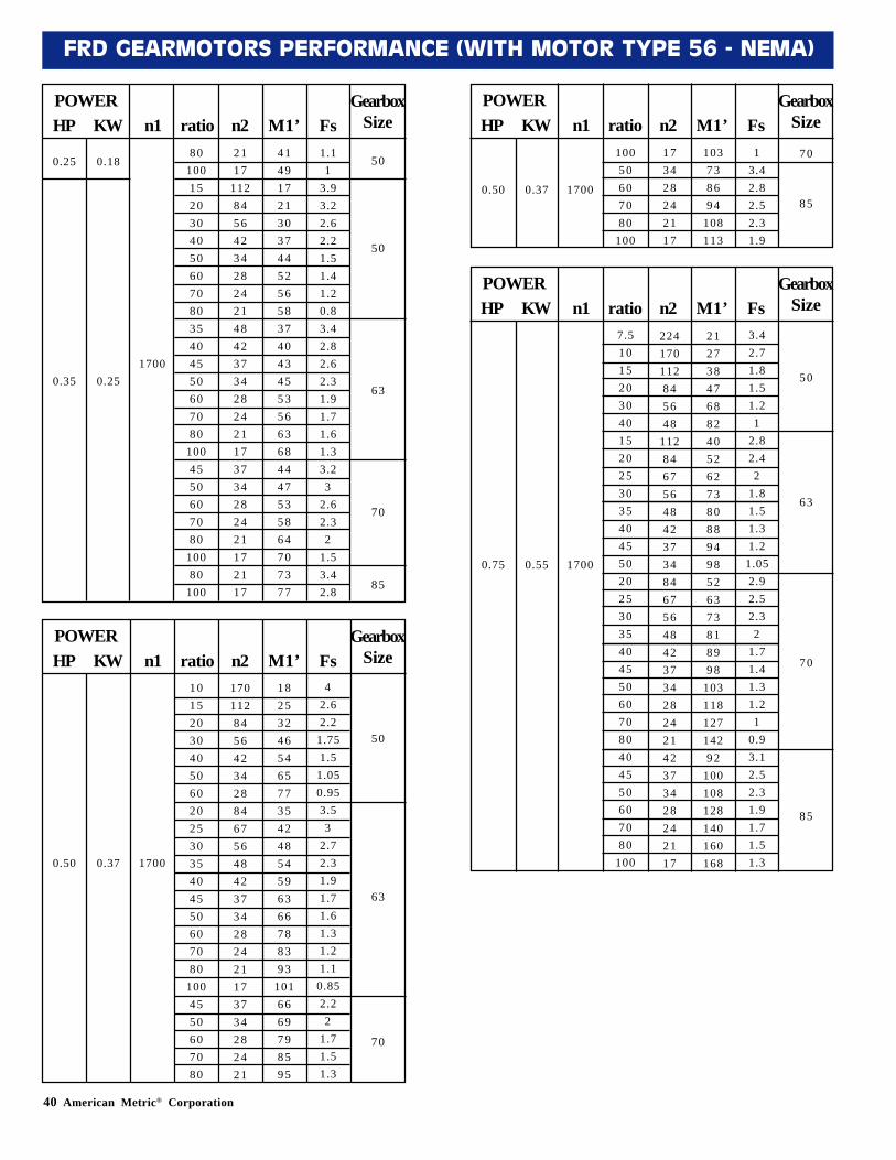
FRD GEARMOTORS PERFORMANCE (WITH MOTOR TYPE 56 - NEMA)
POWERHP KW n1 ratio n2 M1’ Fs
GearboxSize
0.25 0.1880
100152030405060708035404550607080
1004550607080
10080
100
2117
1128456423428242148423734282421173734282421172117
4149172130374452565837404345535663684447535864707377
1.11
3.93.22.62.21.51.41.20.83.42.82.62.31.91.71.61.33.23
2.62.32
1.53.42.8
50
50
63
70
85
0.35 0.251700
POWERHP KW n1 ratio n2 M1’ Fs
GearboxSize
POWERHP KW n1 ratio n2 M1’ Fs
GearboxSize
1015203040506020253035404550607080
1004550607080
10050607080
100
170112845642342884675648423734282421173734282421
173428242117
1825324654657735424854596366788393
1016669798595
103738694
108113
42.62.21.751.51.050.953.53
2.72.31.91.71.61.31.21.10.852.22
1.71.51.3
13.42.82.52.31.9
50
63
70
70
850.50 0.37 1700
0.50 0.37 1700
POWERHP KW n1 ratio n2 M1’ Fs
GearboxSize
7.51015203040152025303540455020253035404550607080404550607080
100
224170112845648
112846756484237348467564842373428242142373428242117
2127384768824052627380889498526373818998
10311812714292
100108128140160168
3.42.71.81.51.21
2.82.42
1.81.51.31.21.052.92.52.32
1.71.41.31.21
0.93.12.52.31.91.71.51.3
0.75 0.55 1700
50
63
70
85
42 American Metric® Corporation
WORM SCREW REDUCTION GEARS AND MOTOR REDUCTION GEARS
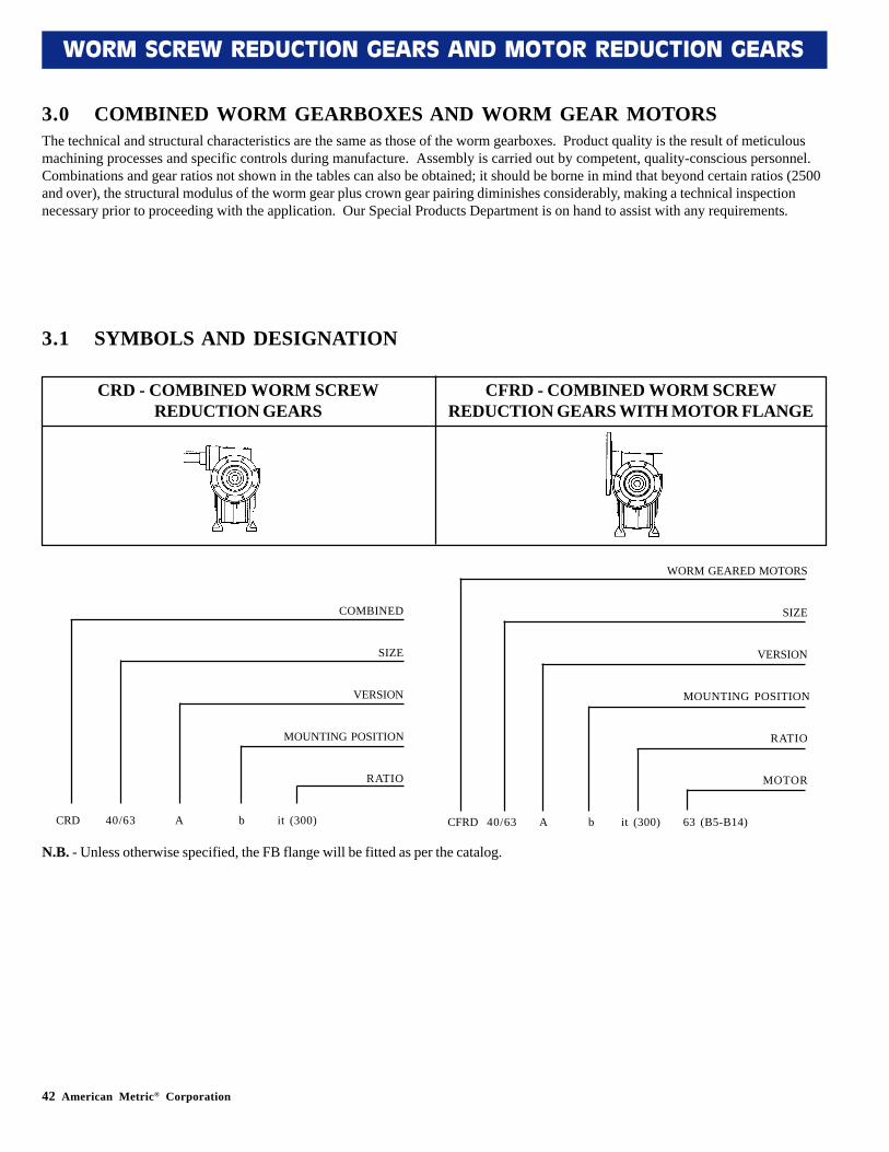
The technical and structural characteristics are the same as those of the worm gearboxes. Product quality is the result of meticulousmachining processes and specific controls during manufacture. Assembly is carried out by competent, quality-conscious personnel.Combinations and gear ratios not shown in the tables can also be obtained; it should be borne in mind that beyond certain ratios (2500and over), the structural modulus of the worm gear plus crown gear pairing diminishes considerably, making a technical inspectionnecessary prior to proceeding with the application. Our Special Products Department is on hand to assist with any requirements.
CRD - COMBINED WORM SCREWREDUCTION GEARS
CFRD - COMBINED WORM SCREWREDUCTION GEARS WITH MOTOR FLANGE
3.0 COMBINED WORM GEARBOXES AND WORM GEAR MOTORS
N.B. - Unless otherwise specified, the FB flange will be fitted as per the catalog.
3.1 SYMBOLS AND DESIGNATION
COMBINED
SIZE
VERSION
MOUNTING POSITION
RATIO
CRD 40/63 A b it (300)
WORM GEARED MOTORS
SIZE
VERSION
MOUNTING POSITION
RATIO
MOTOR
CFRD 40/63 A b it (300) 63 (B5-B14)
American Metric® Corporation 43
WORM SCREW REDUCTION GEARS AND MOTOR REDUCTION GEARS
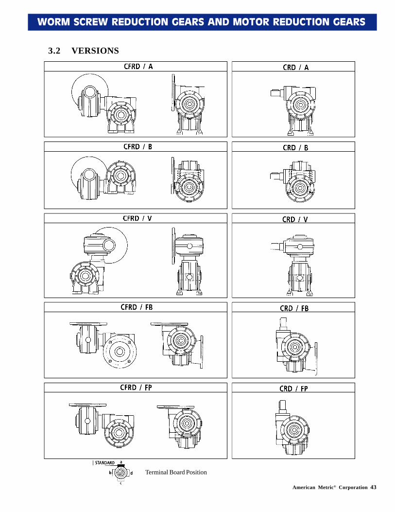
3.2 VERSIONS
Terminal Board Position
44 American Metric® Corporation
WORM SCREW REDUCTION GEARS AND MOTOR REDUCTION GEARS
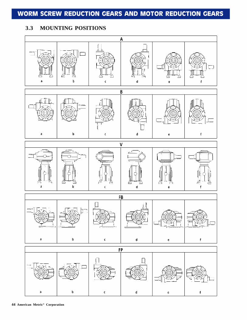
3.3 MOUNTING POSITIONS
American Metric® Corporation 45
WORM SCREW REDUCTION GEARS AND MOTOR REDUCTION GEARS
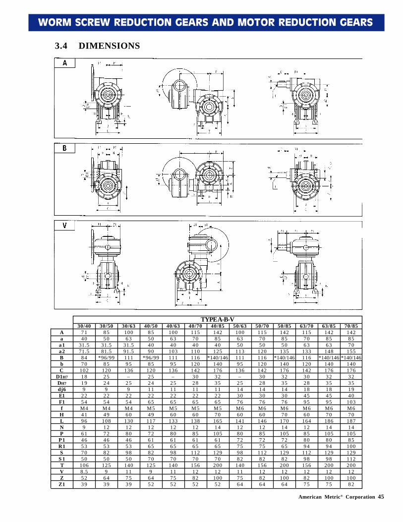
3.4 DIMENSIONS
TYPE A-B-V30/40
7140
31.571.58470
10218199
2254M441969
6146537050
1068.55239
30/508550
31.581.5
*96/9985
12025249
2254M449
108127246538250
1259
6439
30/6310063
31.591.511195
136–
259
2254M460
130128046539850
140117539
40/5085504090
*96/9985
1202524112265M549
117127261658270
1259
6452
40/631006340
10311195
136–
25112265M560
133128061659870
140117552
40/701157040
1101161201423028112265M560
13812856165
11270
156128252
40/851428540
125*140/146
1401763235112265M570
16514
1056165
12970
20012
10052
50/631006350
11311195
136–
25143076M660
141128072759882
140117564
50/701157050
1201161201423028143076M660
14612857275
11282
156128264
50/851428550
135*140/146
1401763235143076M670
17014
1057265
12982
20012
10064
63/701157063
1331161201423028184595M660
16412858094
11298
156128275
63/851428563
148*140/146
1401763235184595M670
18614
1058094
12998
20012
10075
70/851428570
155*140/146
14017632351940
103M670
18714
10585
10012911220012
10082
Aa
a1a2BbC
D1H7DH7dj6E1F1fHLNP
P1R1S
S 1TVZ
Z1
46 American Metric® Corporation
WORM SCREW REDUCTION GEARS AND MOTOR REDUCTION GEARS
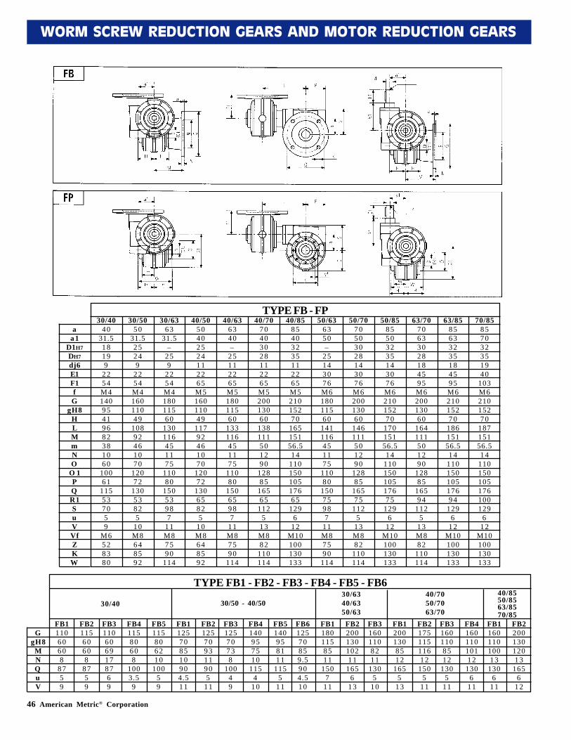
TYPE FB - FP30/40
4031.518199
2254M414095419682381060
10061
115537059
M6528380
30/5050
31.525249
2254M416011049
10892461070
12072
13053825
10M8648592
30/6363
31.5–
259
2254M418011560
130116451175
11080
15053987
11M87590
114
40/5050402524112265M516011049
11792461070
12072
13065825
10M8648592
40/636340–
25112265M518011560
133116451175
11080
15065987
11M87590
114
40/7070403028112265M520013060
138111501290
12885
16565
1125
13M882
110114
40/8585403235112265M521015270
16515156.514
11015010517665
1296
12M10100130133
50/636350–
25143076M618011560
141116451175
11080
15075987
11M87590
114
50/7070503028143076M620013060
146111501290
12885
16575
1125
13M882
110114
50/8585503235143076M621015270
17015156.514
11015010517675
1296
12M10100130133
63/7070633028184595M620013060
164111501290
12885
16594
1125
13M882
110114
63/8585633235184595M621015270
18615156.514
11015010517694
1296
12M10100130133
70/85857032351940
103M621015270
18715156.514
110150105176100129
612
M10100130133
aa1
D1H7DH7dj6E1F1fG
gH8HLMmNO
O 1PQR1SuVVfZKW
FB220013012013
1656
12
FB116011010013
1306
11
FB416011010112
1306
11
FB217511511612
1505
11
FB12001308512
1655
13
FB31601108512
1305
11
FB220013010211
1656
13
FB11801158511
1507
11
FB31601108211
1305
10
FB5140958111
1155
11
FB4140957510
1154
10
FB612570859.5904.510
FB2125709311905
11
FB1125708510904.511
FB312570738
10049
FB5115806210
10059
FB411580608
1003.59
FB211560608
8759
FB111060608
8759
FB31106069178769
GgH8
MNQuV
30/40 30/50 - 40/5030/6340/6350/63
40/7050/7063/70
40/8550/8563/8570/85
TYPE FB1 - FB2 - FB3 - FB4 - FB5 - FB6
American Metric® Corporation 47
WORM SCREW REDUCTION GEARS AND MOTOR REDUCTION GEARS
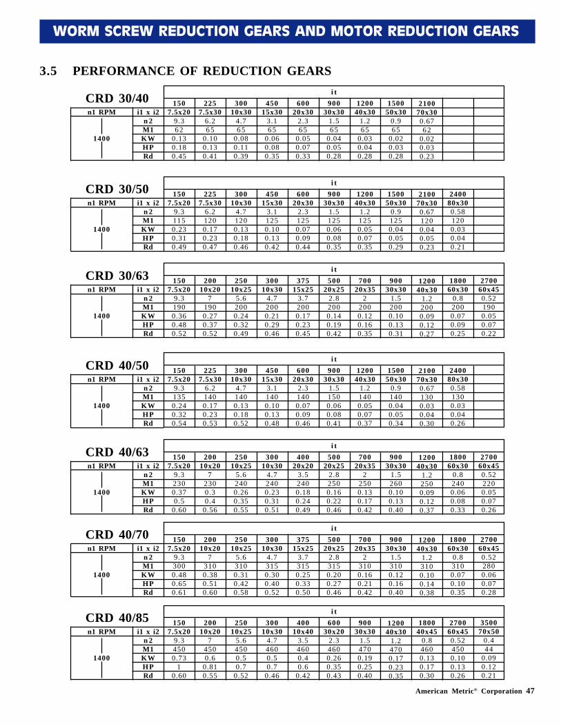
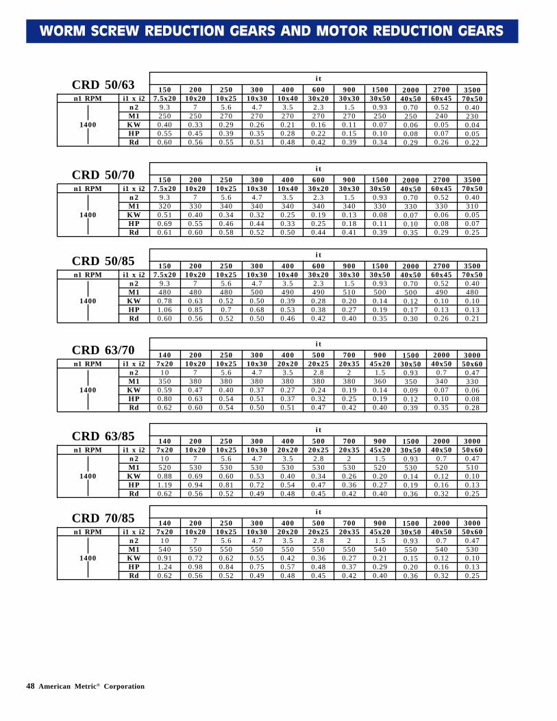
3.5 PERFORMANCE OF REDUCTION GEARS
210070x300.6762
0.020.030.23
150050x30
0.965
0.020.030.28
120040x30
1.265
0.030.040.28
90030x30
1.565
0.040.050.28
60020x30
2.365
0.050.070.33
45015x30
3.165
0.060.080.35
30010x30
4.765
0.080.110.39
2257.5x30
6.265
0.100.130.41
1507.5x20
9.362
0.130.180.45
i1 x i2n 2M1KWHPRd
n1 RPM
1400
i tCRD 30/40
210070x300.671200.040.050.23
150050x30
0.91250.040.050.29
120040x30
1.21250.050.070.35
90030x30
1.51250.060.080.35
60020x30
2.31250.070.090.44
45015x30
3.11250.100.130.42
30010x30
4.71200.130.180.46
2257.5x30
6.21200.170.230.47
1507.5x20
9.31150.230.310.49
i1 x i2n 2M1KWHPRd
n1 RPM
1400
i tCRD 30/50
120040x30
1.22000.090.120.27
90030x30
1.52000.100.130.31
70020x35
22000.120.160.35
50020x25
2.82000.140.190.42
37515x25
3.72000.170.230.45
30010x30
4.72000.210.290.46
25010x25
5.62000.240.320.49
20010x20
71900.270.370.52
1507.5x20
9.31900.360.480.52
i1 x i2n 2M1KWHPRd
n1 RPM
1400
i tCRD 30/63
210070x300.671300.030.040.30
150050x30
0.91400.040.050.34
120040x30
1.21400.050.070.37
90030x30
1.51500.060.080.41
60020x30
2.31400.070.090.46
45015x30
3.11400.100.130.48
30010x30
4.71400.130.180.52
2257.5x30
6.21400.170.230.53
1507.5x20
9.31350.240.320.54
i1 x i2n 2M1KWHPRd
n1 RPM
1400
i tCRD 40/50
120040x30
1.22500.090.120.37
90030x30
1.52600.100.130.40
70020x35
22500.130.170.42
50020x25
2.82500.160.220.46
40020x20
3.52400.180.240.49
30010x30
4.72400.230.310.51
25010x25
5.62400.260.350.55
20010x20
72300.30.4
0.56
1507.5x20
9.32300.370.5
0.60
i1 x i2n 2M1KWHPRd
n1 RPM
1400
i tCRD 40/63
120040x30
1.23100.100.140.38
90030x30
1.53100.120.160.40
70020x35
23100.160.210.42
50020x25
2.83150.200.270.46
37515x25
3.73150.250.330.50
30010x30
4.73150.300.400.52
25010x25
5.63100.310.420.58
20010x20
73100.380.510.60
1507.5x20
9.33000.480.650.61
i1 x i2n 2M1KWHPRd
n1 RPM
1400
i tCRD 40/70
1507.5x20
9.34500.73
10.60
i1 x i2n 2M1KWHPRd
n1 RPM
1400
i tCRD 40/85
240080x300.581200.030.040.21
180060x30
0.82000.070.090.25
270060x450.521900.050.070.22
240080x300.581300.030.040.26
180060x30
0.82400.060.080.33
270060x450.522200.050.070.26
180060x30
0.83100.070.100.35
270060x450.522800.060.070.28
120040x30
1.24700.170.230.35
90030x30
1.54700.190.250.40
60030x20
2.34600.260.350.43
40010x40
3.54600.40.6
0.42
30010x30
4.74600.50.7
0.46
25010x25
5.64500.50.7
0.52
20010x20
74500.6
0.810.55
180040x45
0.84600.130.170.30
270060x450.524500.100.130.26
350070x50
0.444
0.090.120.21
48 American Metric® Corporation
WORM SCREW REDUCTION GEARS AND MOTOR REDUCTION GEARS
200040x500.702500.060.080.29
150030x500.932500.070.100.34
90030x30
1.52700.110.150.39
60030x20
2.32700.160.220.42
40010x40
3.52700.210.280.48
30010x30
4.72700.260.350.51
25010x25
5.62700.290.390.55
20010x20
72500.330.450.56
1507.5x20
9.32500.400.550.60
i1 x i2n 2M1KWHPRd
n1 RPM
1400
i tCRD 50/63
200040x500.703300.070.100.35
150030x500.933300.080.110.39
90030x30
1.53400.130.180.41
60030x20
2.33400.190.250.44
40010x40
3.53400.250.330.50
30010x30
4.73400.320.440.52
25010x25
5.63400.340.460.58
20010x20
73300.400.550.60
1507.5x20
9.33200.510.690.61
i1 x i2n 2M1KWHPRd
n1 RPM
1400
i tCRD 50/70
200040x500.705000.120.170.30
150030x500.935000.140.190.35
90030x30
1.55100.200.270.40
60030x20
2.34900.280.380.42
40010x40
3.54900.390.530.46
30010x30
4.75000.500.680.50
25010x25
5.64800.520.7
0.52
20010x20
74800.630.850.56
1507.5x20
9.34800.781.060.60
i1 x i2n 2M1KWHPRd
n1 RPM
1400
i tCRD 50/85
150030x500.933500.090.120.39
90045x20
1.53600.140.190.40
70020x35
23800.190.250.42
50020x25
2.83800.240.320.47
40020x20
3.53800.270.370.51
30010x30
4.73800.370.510.50
25010x25
5.63800.400.540.54
20010x20
73800.470.630.60
1407x20
103500.590.800.62
i1 x i2n 2M1KWHPRd
n1 RPM
1400
i tCRD 63/70
150030x500.935300.140.190.36
90045x20
1.55200.200.270.40
70020x35
25300.260.360.42
50020x25
2.85300.340.470.45
40020x20
3.55300.400.540.48
30010x30
4.75300.530.720.49
25010x25
5.65300.600.810.52
20010x20
75300.690.940.56
1407x20
105200.881.190.62
i1 x i2n 2M1KWHPRd
n1 RPM
1400
i tCRD 63/85
150030x500.935500.150.200.36
90045x20
1.55400.210.290.40
70020x35
25500.270.370.42
50020x25
2.85500.360.480.45
40020x20
3.55500.420.570.48
30010x30
4.75500.550.750.49
25010x25
5.65500.620.840.52
20010x20
75500.720.980.56
1407x20
105400.911.240.62
i1 x i2n 2M1KWHPRd
n1 RPM
1400
i tCRD 70/85
270060x450.523300.060.080.29
270060x450.524900.100.130.26
350070x500.404800.100.130.21
200040x50
0.73400.070.100.35
200040x50
0.75200.120.160.32
300050x600.475100.100.130.25
200040x50
0.75400.120.160.32
300050x600.475300.100.130.25
350070x500.402300.040.050.22
270060x450.522400.050.070.26
350070x500.403100.050.070.25
300050x600.473300.060.080.28
American Metric® Corporation 49
WORM SCREW REDUCTION GEARS AND MOTOR REDUCTION GEARS
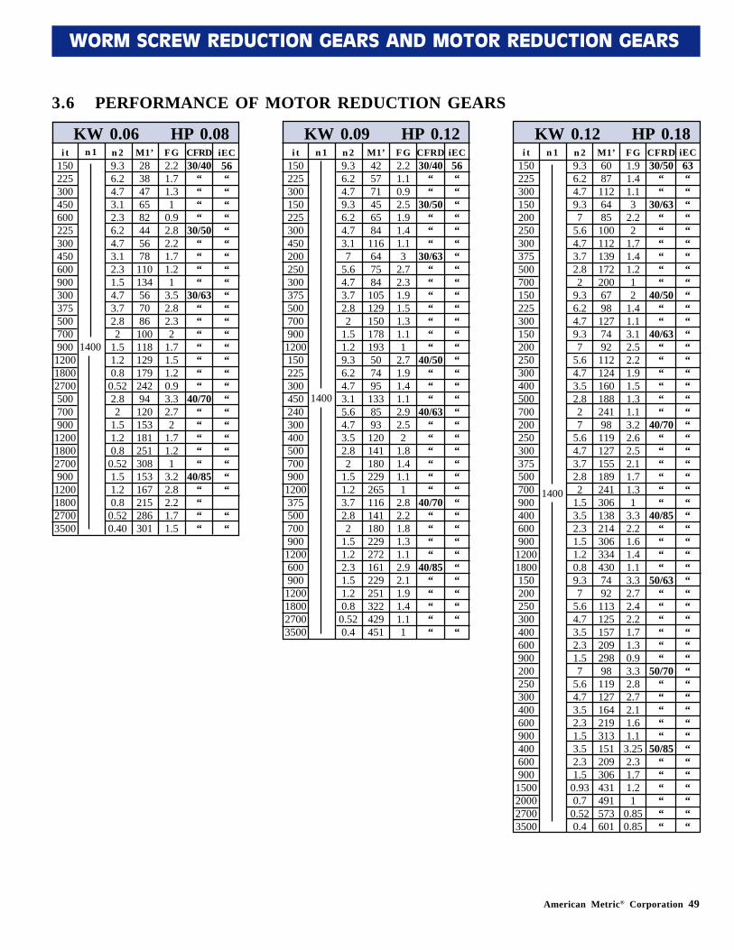
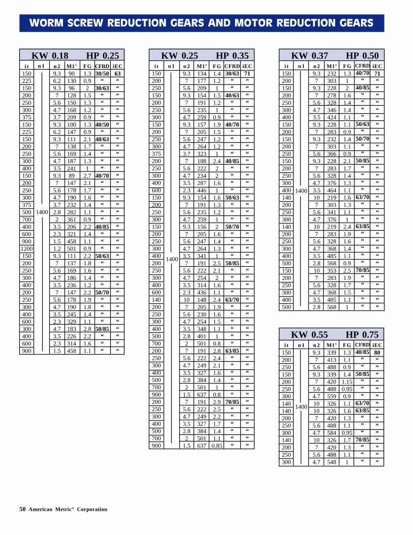
3.6 PERFORMANCE OF MOTOR REDUCTION GEARS
KW 0.06 HP 0.08i t
150225300450600225300450600900300375500700900
120018002700500700900
120018002700900
1200180027003500
n 1 n 29.36.24.73.12.36.24.73.12.31.54.73.72.82
1.51.20.8
0.522.82
1.51.20.8
0.521.51.20.8
0.520.40
M1’2838476582445678
110134567086
10011812917924294
120153181251308153167215286301
FG2.21.71.31
0.92.82.21.71.21
3.52.82.32
1.71.51.20.93.32.72
1.71.21
3.22.82.21.71.5
CFRD30/40
““““
30/50““““
30/63“““““““
40/70“““““
40/85““““
iEC56“““““““““““““““““““““““““
““
KW 0.09 HP 0.12i t
150225300150225300450200250300375500700900
1200150225300450240300400500700900
1200375500700900
1200600900
1200180027003500
n 1 n 29.36.24.79.36.24.73.17
5.64.73.72.82
1.51.29.36.24.73.15.64.73.52.82
1.51.23.72.82
1.51.22.31.51.20.8
0.520.4
M1’425771456584
116647584
105129150178193507495
1338593
120141180229265116141180229272161229251322429451
FG2.21.10.92.51.91.41.13
2.72.31.91.51.31.11
2.71.91.41.12.92.52
1.81.41.11
2.82.21.81.31.12.92.11.91.41.11
CFRD30/40
““
30/50“““
30/63“““““““
40/50“““
40/63““““““
40/70““““
40/85“““““
iEC56““““““““““““““““““““““““““““““““““““
1400
KW 0.12 HP 0.18n 1 n 2
9.36.24.79.37
5.64.73.72.82
9.36.24.79.37
5.64.73.52.827
5.64.73.72.82
1.53.52.31.51.20.89.37
5.64.73.52.31.57
5.64.73.52.31.53.52.31.5
0.930.7
0.520.4
M1’608711264851001121391722006798127749211212416018824198119127155189241306138214306334430749211312515720929898119127164219313151209306431491573601
FG1.91.41.13
2.22
1.71.41.212
1.41.13.12.52.21.91.51.31.13.22.62.52.11.71.31
3.32.21.61.41.13.32.72.42.21.71.30.93.32.82.72.11.61.1
3.252.31.71.21
0.850.85
CFRD30/50
““
30/63““““““
40/50““
40/63““““““
40/70““““““
40/85““““
50/63““““““
50/70“““““
50/85““““““
iEC63“““““““““““““““““““““““““““““““““““““““““““““““““““
i t150225300150200250300375500700150225300150200250300400500700200250300375500700900400600900
12001800150200250300400600900200250300400600900400600900
1500200027003500
1400
1400
50 American Metric® Corporation
WORM SCREW REDUCTION GEARS AND MOTOR REDUCTION GEARS
KW 0.18 HP 0.25i t
150225150200250300375150225150200250300400150200250300375500700400600900
1200150200250300400200250300400600300400600900
n 1 n 29.36.29.37
5.64.73.79.36.29.37
5.64.73.59.37
5.64.73.72.82
3.52.31.51.29.37
5.64.73.57
5.64.73.52.34.73.52.31.5
M1’90
13096
12815016820910014711113816918724189
147178190232282361206321458501111137169186236147178190245329183226314458
FG1.30.92
1.51.31.20.91.30.92.11.71.41.31
2.72.11.71.61.41.10.92.21.41.10.92.21.81.61.41.22.21.91.81.41.12.82.21.61.1
CFRD30/50
“30/63
““““
40/50“
40/63““““
40/70““““““
40/85“““
50/63““““
50/70““““
50/85“““
iEC63““““““““““““““““““““““““““““““““““““““
KW 0.37 HP 0.50i t
150200150200250300400150200150200250150200250300400140200250300140200250300400500150200250300400500
n 1 n 29.37
9.37
5.64.73.59.37
9.37
5.69.37
5.64.73.5107
5.64.7107
5.64.73.52.8107
5.64.73.52.8
M1’232303228278328346424228283232303366228283328376464219303341376219283328368485568353283328368485568
FG1.312
1.61.41.41.11.10.91.41.10.92.11.71.41.31.11.61.31.11
2.41.91.61.41.10.92.51.91.71.51.11
CFRD40/70
“40/85
““““
50/63“
50/70““
50/85““““
63/70“““
63/85“““““
70/85“““““
iEC71““““““““““““““““““““““““““““““““
1400
KW 0.25 HP 0.35n 1 n 2
9.37
5.69.37
5.64.79.37
5.64.73.77
5.64.73.52.39.37
5.64.79.37
5.64.73.57
5.64.73.52.3107
5.64.73.52.827
5.64.73.52.82
1.57
5.64.73.52.82
1.5
M1’134177209154191235259157205247264323188222234287446154191235259156205247264341191222254314436148205230254348401501191222249327384501637191222249327384501637
FG1.41.21
1.51.21
0.91.91.51.21.21
2.422
1.61
1.61.31.212
1.61.41.31
2.52.12
1.61.12.41.91.61.51.11
0.82.82.42.11.61.41
0.82.92.52.21.71.41.10.85
CFRD30/63
““
40/63“““
40/70““““
40/85““““
50/63“““
50/70““““
50/85““““
63/70““““““
63/85““““““
70/85““““““
iEC71“““““““““““““““““““““““““““““““““““““““““““““““““““
i t150200250150200250300150200250300375200250300400600150200250300150200250300400200250300400600140200250300400500700200250300400500700900200250300400500700900
1400
1400
KW 0.55 HP 0.75i t
150200250150200250300140140200250300140200250300
n 1 n 29.37
5.69.37
5.64.710107
5.64.7107
5.64.7
M1’339413488339420488559326326420488584326420488548
FG1.31.10.91.41.150.950.91.11.61.31.10.951.71.31.11
CFRD40/85
““
50/85“““
63/7063/85
“““
70/85“““
iEC80“““““““““““““““
1400

52 American Metric® Corporation
WORM SCREW REDUCTION GEARS AND MOTOR REDUCTION GEARS
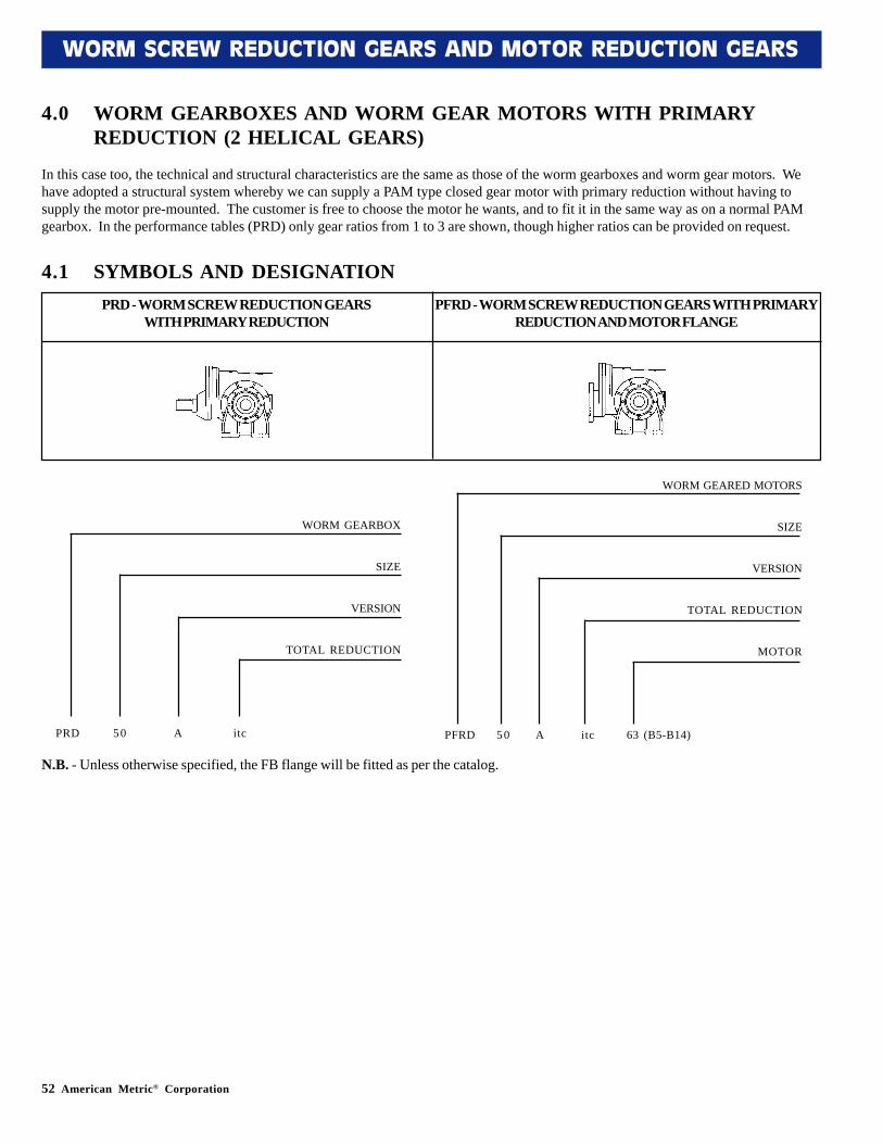
In this case too, the technical and structural characteristics are the same as those of the worm gearboxes and worm gear motors. Wehave adopted a structural system whereby we can supply a PAM type closed gear motor with primary reduction without having tosupply the motor pre-mounted. The customer is free to choose the motor he wants, and to fit it in the same way as on a normal PAMgearbox. In the performance tables (PRD) only gear ratios from 1 to 3 are shown, though higher ratios can be provided on request.
PRD - WORM SCREW REDUCTION GEARSWITH PRIMARY REDUCTION
PFRD - WORM SCREW REDUCTION GEARS WITH PRIMARYREDUCTION AND MOTOR FLANGE
4.0 WORM GEARBOXES AND WORM GEAR MOTORS WITH PRIMARYREDUCTION (2 HELICAL GEARS)
N.B. - Unless otherwise specified, the FB flange will be fitted as per the catalog.
4.1 SYMBOLS AND DESIGNATION
WORM GEARBOX
SIZE
VERSION
TOTAL REDUCTION
PRD 50 A itc
WORM GEARED MOTORS
SIZE
VERSION
TOTAL REDUCTION
MOTOR
PFRD 50 A itc 63 (B5-B14)
American Metric® Corporation 53
WORM SCREW REDUCTION GEARS AND MOTOR REDUCTION GEARS
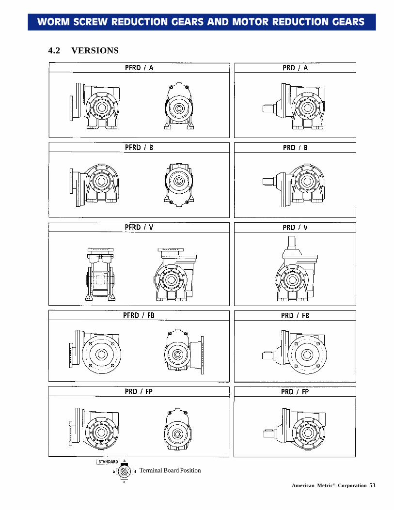
4.2 VERSIONS
Terminal Board Position
54 American Metric® Corporation
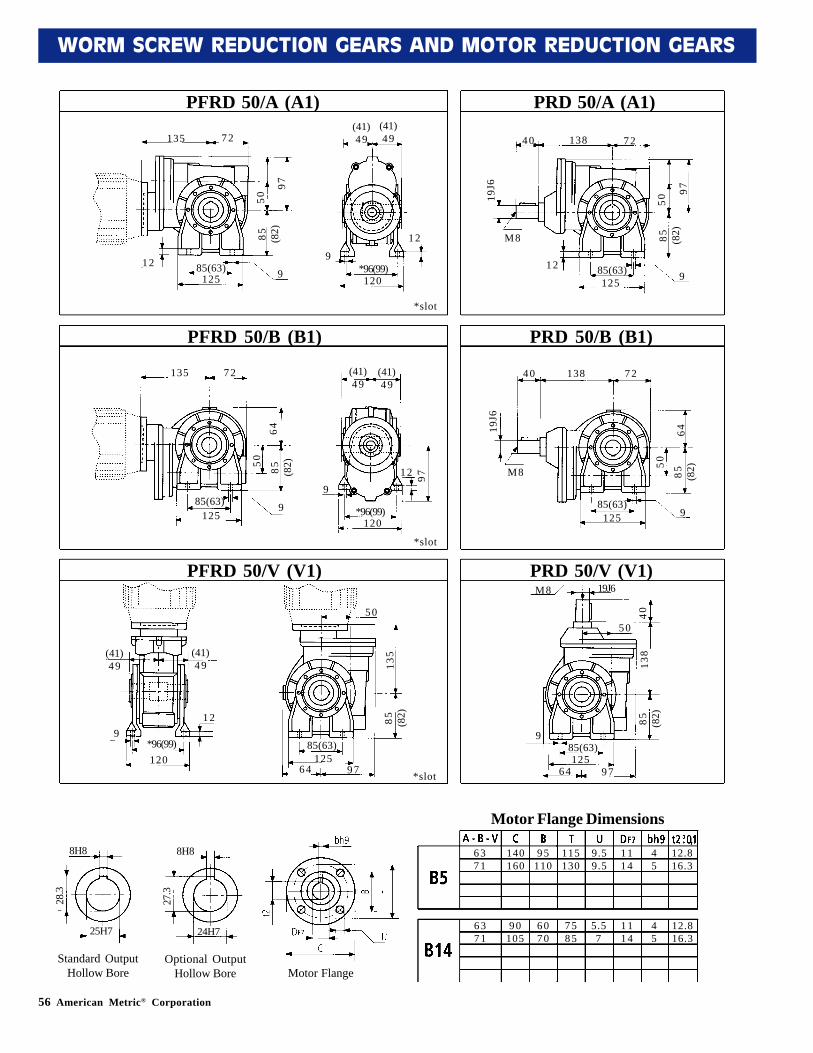
WORM SCREW REDUCTION GEARS AND MOTOR REDUCTION GEARS
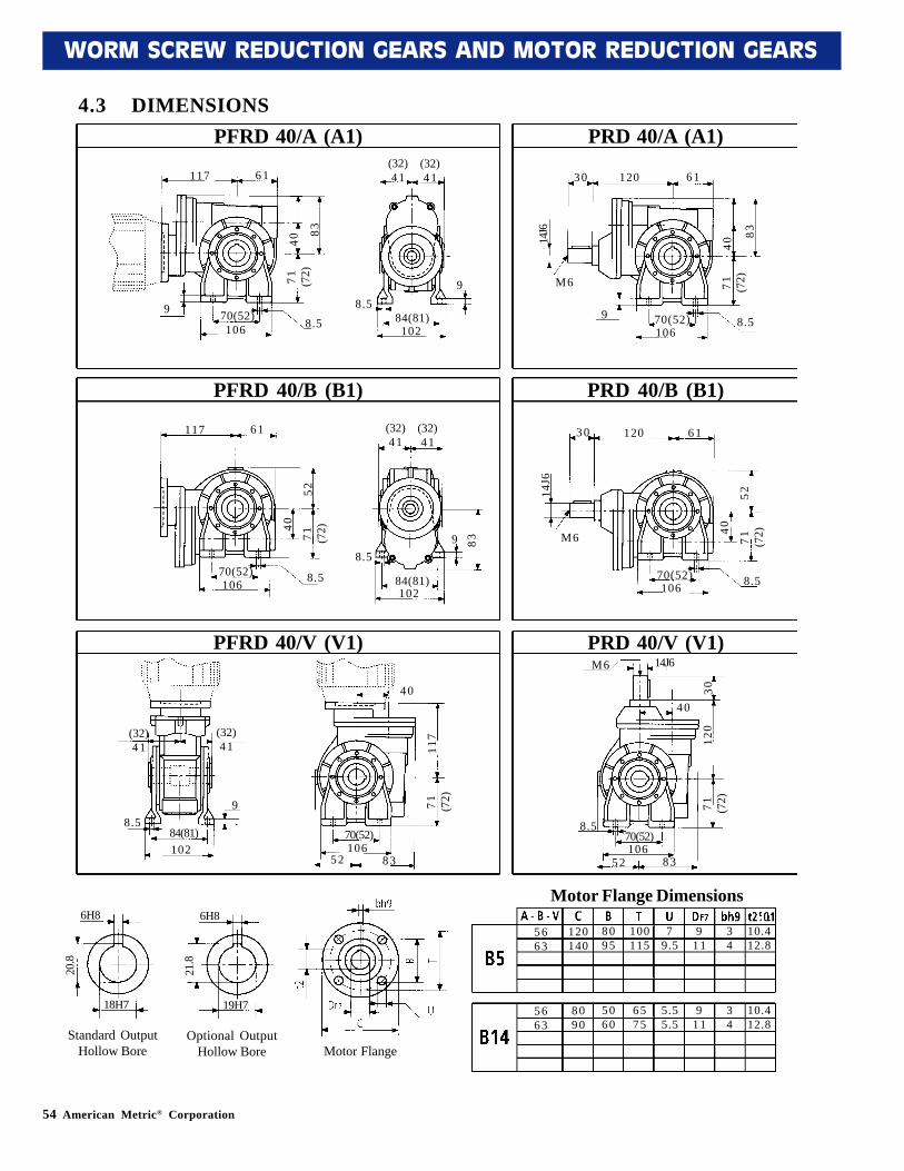
4.3 DIMENSIONSPFRD 40/A (A1) PRD 40/A (A1)
PFRD 40/B (B1) PRD 40/B (B1)
PFRD 40/V (V1) PRD 40/V (V1)
117 61
9
10670(52)
83
4071 (7
2)8 .5
8.584(81)102
9
(32)41
(32)41 30 120 61
M6
9 70(52)106
8.5
83
4071 (7
2)
14J6
117 61
10670(52)
52
40
71 (72)
8 .5
8.5
84(81)102
9
(32)41
(32)41
30 120 61
M6
70(52)106 8.5
52
40
71 (72)
14J6
83
(32)41
(32)41
8.59
84(81)102
40
70(52)106
52 83
71 (72)
117
71 (72)
120
304 0
14J6M6
8.570(52)106
52 83
5663
120140
8095
100115
79.5
911
34
10.412.8
5663
8090
5060
6575
5.55.5
911
34
10.412.8
6H8
19H7
21.8
6H8
18H7
20.8
standard
t2
TB
UC
DF7
bh9 5H8
14H7
16.3
Motor Flange Dimensions6H8
18H7
20.8
Standard OutputHollow Bore
6H8
19H7
21.8
Optional OutputHollow Bore Motor Flange
American Metric® Corporation 55
WORM SCREW REDUCTION GEARS AND MOTOR REDUCTION GEARS
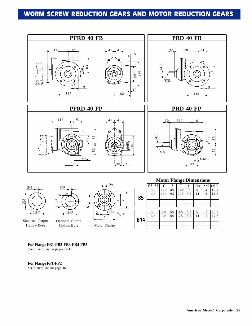
PFRD 40 FB PRD 40 FB
117 61
8340
9
115
41 415
1082
140
95H
8
3 0 120 61
14J6
40
M6
9
115
PFRD 40 FP PRD 40 FP
117 61
83
40
M6x883
41 41
238
100
60H
8
3 0 120 61
14J6
40
M6
M6x883
52
8352
5 663
120140
8095
100115
79.5
911
34
10.412.8
5663
8090
5060
6575
5.55.5
911
34
10.412.8
6H8
19H7
21.8
6H8
18H7
20.8
standard
For Flange FB1-FB2-FB3-FB4-FB5See dimensions on pages 14-15
For Flange FP1-FP2See dimensions on page 16
5H8
14H7
16.3
Motor Flange
6H8
19H7
21.8
Optional OutputHollow Bore
6H8
18H7
20.8
Standard OutputHollow Bore
Motor Flange Dimensions
56 American Metric® Corporation
WORM SCREW REDUCTION GEARS AND MOTOR REDUCTION GEARS
PRD 50/A (A1)PFRD 50/A (A1)
135 72
12125
85(63)9
9
12
120*96(99)
(41)49
(41)49
*slot
97
5085 (8
2)
4 0 138 72
12585(63)12
9
M8
97
5085 (8
2)
19J6
PFRD 50/B (B1) PRD 50/B (B1)
135 72
12585(63) 9
912
120*96(99)
(41)49
(41)49
*slot
6450 85 (82)
97
4 0 138 72
12585(63)
9
M8
64
50
85 (82)
19J6
PRD 50/V (V1)M8 19J6
4013
885 (8
2)
12585(63)
64 97
9
50
PFRD 50/V (V1)
50
(41)49
(41)49
9*96(99)120
12
85(63)125
64 97
85 (82)
135
6 371
140160
95110
115130
9.59.5
1114
45
12.816.3
6371
90105
6070
7585
5.57
1114
45
12.816.3
8H8
25H7
28.3
8H8
24H7
27.3
standard
*slot
6H8
19H7
21.8
6H8
18H7
20.8
standard
t2
TB
UC
DF7
bh9 5H8
14H7
16.3
Motor Flange
8H8
24H7
27.3
Optional OutputHollow Bore
8H8
25H7
28.3
Standard OutputHollow Bore
Motor Flange Dimensions
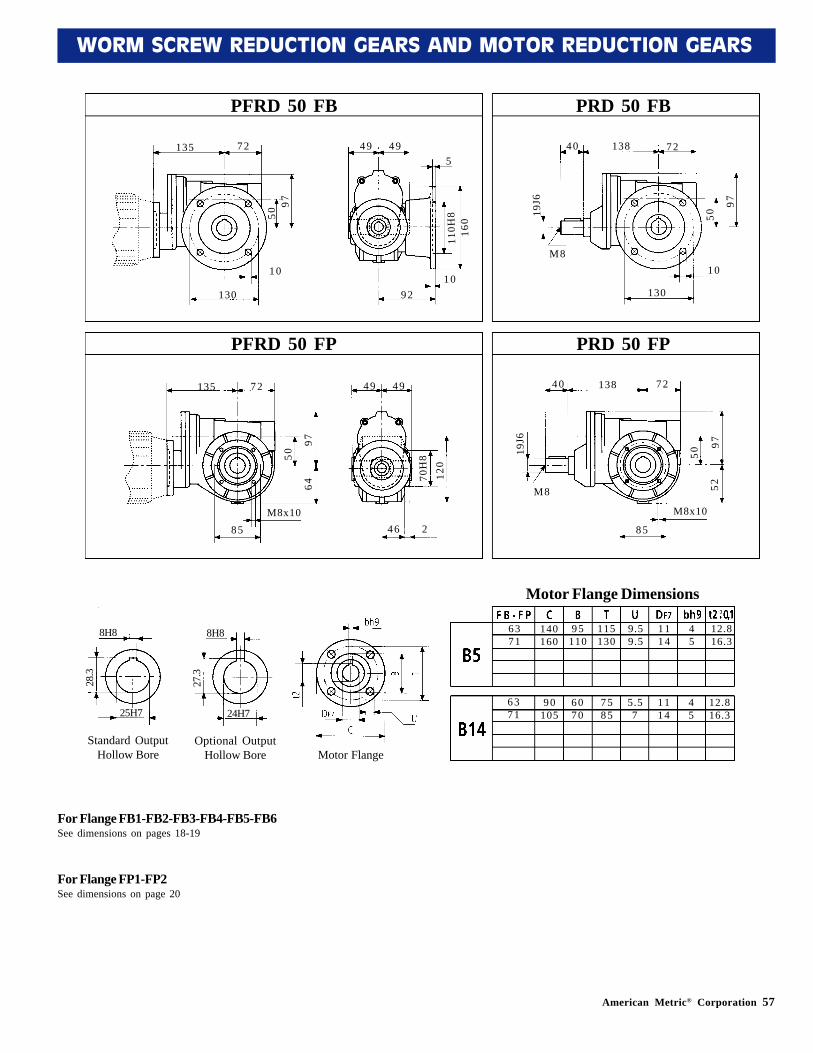
American Metric® Corporation 57
WORM SCREW REDUCTION GEARS AND MOTOR REDUCTION GEARS
PRD 50 FBPFRD 50 FB
PRD 50 FPPFRD 50 FP
135 72
130
1010
92
49 49
9750
160
110H
8
540 138 72
130
10M8
97
5019J6
135 72
85M8x10
46
49 49
97
50
120
70H
8
2
40 138 72
85
M8x10
M8
97
5019J6
5264
6 371
140160
95110
115130
9.59.5
1114
45
12.816.3
6371
90105
6070
7585
5.57
1114
45
12.816.3
8H8
25H7
28.3
8H8
24H7
27.3
standard
For Flange FB1-FB2-FB3-FB4-FB5-FB6See dimensions on pages 18-19
For Flange FP1-FP2See dimensions on page 20
6H8
19H7
21.8
6H8
18H7
20.8
standard
t2
TB
UC
DF7
bh9 5H8
14H7
16.3
Motor Flange
8H8
24H7
27.3
Optional OutputHollow Bore
8H8
25H7
28.3
Standard OutputHollow Bore
Motor Flange Dimensions
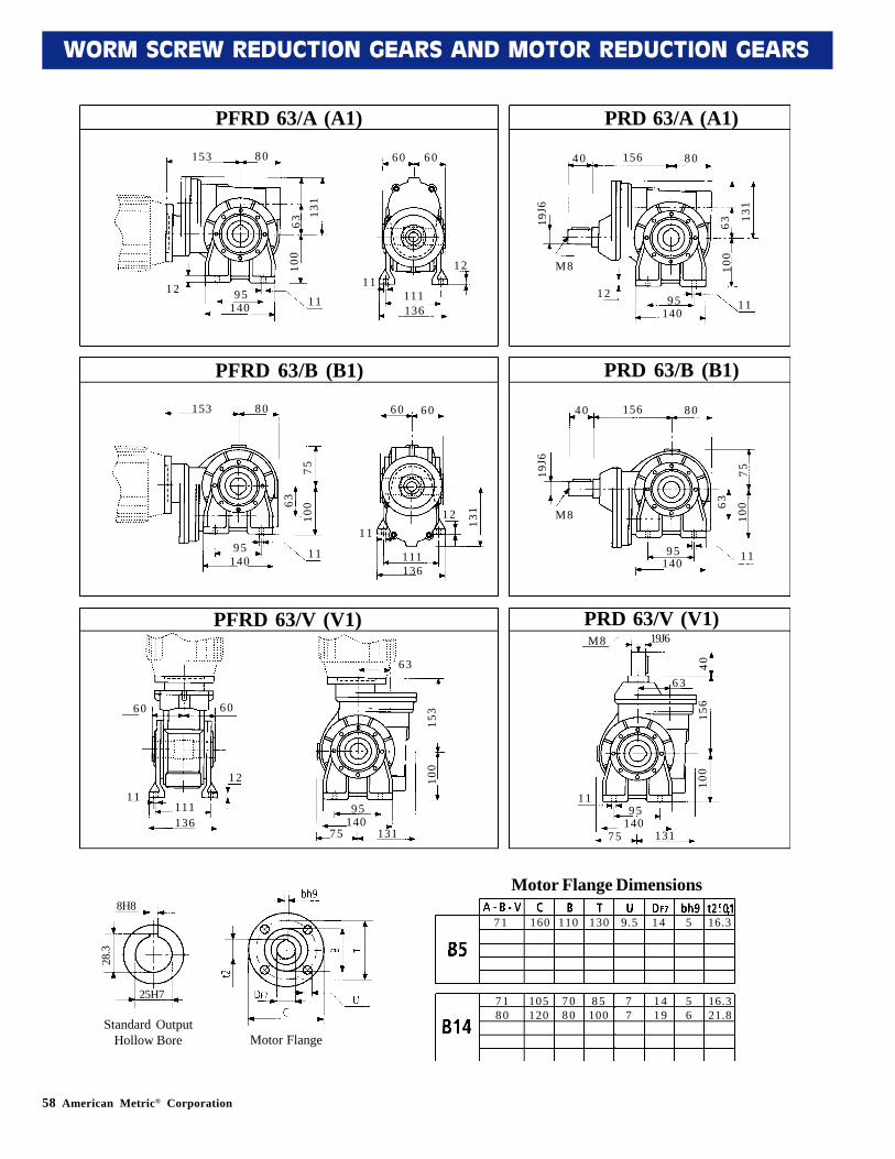
58 American Metric® Corporation
WORM SCREW REDUCTION GEARS AND MOTOR REDUCTION GEARS
PRD 63/A (A1)PFRD 63/A (A1)
153 80
1214095
11
11
12
136111
60 60
131
6310
0
4 0 156 80
1409512
11
M8
131
6310
0
19J6
PRD 63/B (B1)PFRD 63/B (B1)
153 80
14095
11
11
12
136111
60 60
7563
100
4 0 156 80
14095 11
M8
75
63
100
19J6
131
PFRD 63/V (V1) PRD 63/V (V1)
60 60
11
12
111136
63
95140
75 131
100
153
100
156
40
6 3
19J6M8
1195
14075 131
71 160 110 130 9.5 14 5 16.3
7180
105120
7080
85100
77
1419
56
16.321.8
8H8
25H7
28.3
6H8
19H7
21.8
6H8
18H7
20.8
standard
t2
TB
UC
DF7
bh9 5H8
14H7
16.3
Motor Flange Dimensions8H8
25H7
28.3
Standard OutputHollow Bore Motor Flange
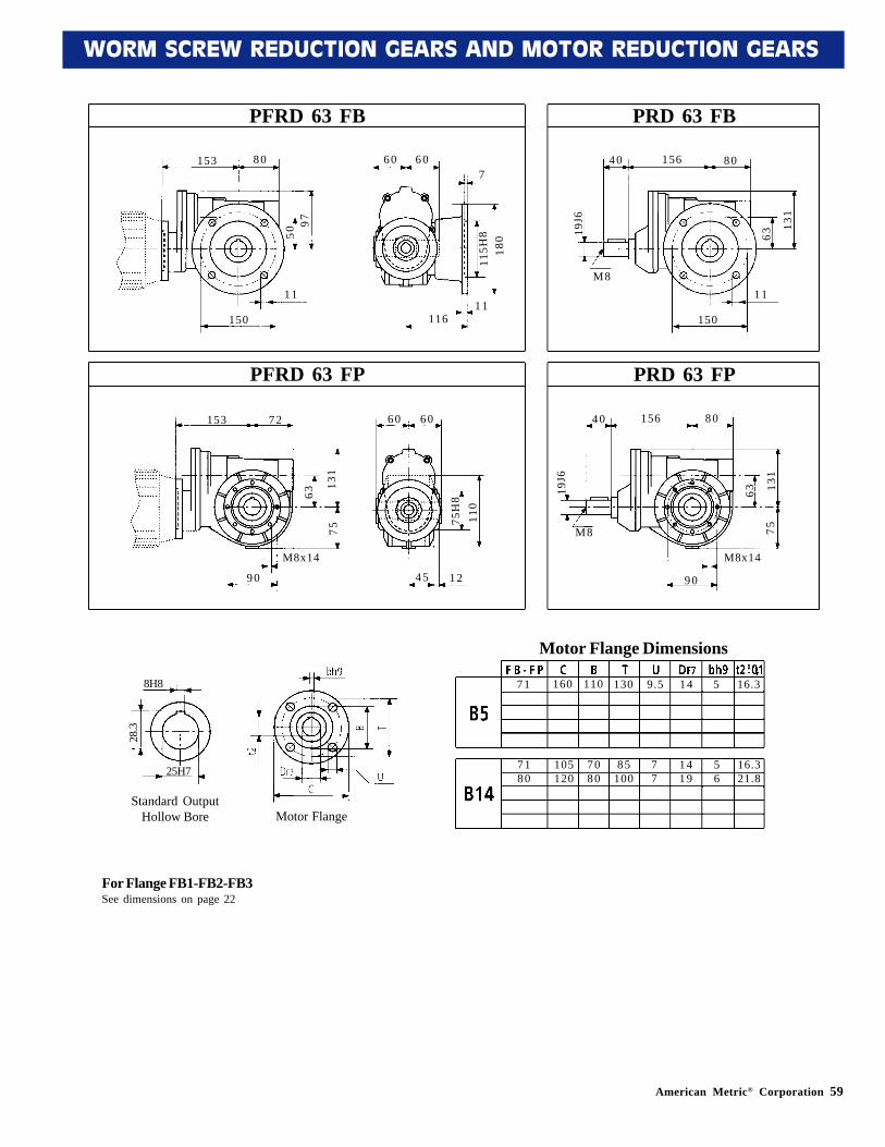
American Metric® Corporation 59
WORM SCREW REDUCTION GEARS AND MOTOR REDUCTION GEARS
PRD 63 FBPFRD 63 FB
PRD 63 FPPFRD 63 FP
153 80
150
1111
116
60 60
9750
180
115H
8
740 156 80
150
11M8
131
6319J6
153 72
90
M8x14
45
60 60
131
63
110
75H
8
1 2
40 156 80
90
M8x14
M8
131
6319J6
7575
7 1 160 110 130 9.5 14 5 16.3
7180
105120
7080
85100
77
1419
56
16.321.8
8H8
25H7
28.3
For Flange FB1-FB2-FB3See dimensions on page 22
Motor Flange Dimensions
8H8
25H7
28.3
Standard OutputHollow Bore Motor Flange
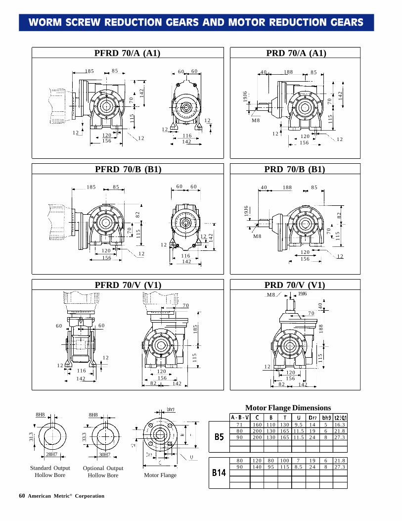
60 American Metric® Corporation
WORM SCREW REDUCTION GEARS AND MOTOR REDUCTION GEARS
PRD 70/A (A1)PFRD 70/A (A1)
185 85
12156120
12
12
12
142116
60 60
142
7011
5
4 0 188 85
15612012
12
M8
142
7011
5
19J6
PFRD 70/B (B1) PRD 70/B (B1)
185 85
156120 12
1212
142116
60 60
8270
115
142
4 0 188 85
156120
12
M8
82
70
115
19J6
PRD 70/V (V1)M8 19J6
4018
811
5
156120
82 142
12
70
PFRD 70/V (V1)
70
60 60
12116142
12
120156
82 142
115
185
7 18090
160200200
110130130
130165165
9.511.511.5
141924
568
16.321.827.3
8090
120140
8095
100115
78.5
1924
68
21.827.3
8H8
30H7
33.3
8H8
28H7
31.3
standard
6H8
19H7
21.8
6H8
18H7
20.8
standard
t2
TB
UC
DF7
bh9 5H8
14H7
16.3
Motor Flange
8H8
30H7
33.3
Optional OutputHollow Bore
8H8
28H7
31.3
Standard OutputHollow Bore
Motor Flange Dimensions

American Metric® Corporation 61
WORM SCREW REDUCTION GEARS AND MOTOR REDUCTION GEARS
PRD 70 FBPFRD 70 FB
PRD 70 FPPFRD 70 FP
185 85
165
1312
111
60 60
142
70
200
130H
8
540 188 85
165
13M8
142
7019J6
185 85
110M8x14
50
60 60
142
70
128
90H
8
7
40 188 85
110
M8x14
M8
142
7019J6
8282
7 18090
160200200
110130130
130165165
9.511.511.5
141924
568
16.321.827.3
8090
120140
8095
100115
78.5
1924
68
21.827.3
8H8
30H7
33.3
8H8
28H7
31.3
For Flange FB1-FB2-FB3-FB3A-FB4See dimensions on pages 25-26
Motor Flange
8H8
30H7
33.3
Optional OutputHollow Bore
8H8
28H7
31.3
Motor Flange Dimensions
Standard OutputHollow Bore
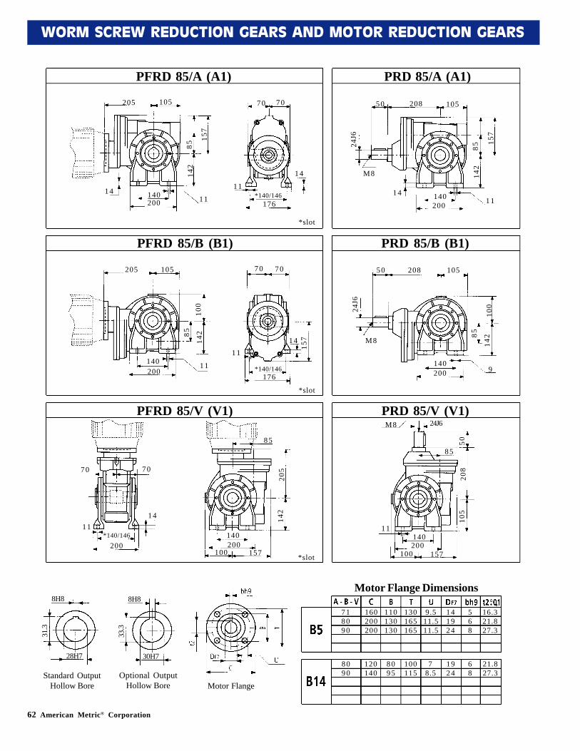
62 American Metric® Corporation
WORM SCREW REDUCTION GEARS AND MOTOR REDUCTION GEARS
PRD 85/A (A1)PFRD 85/A (A1)
205 105
14200140
11
11
14
176*140/146
70 70
*slot
157
8514
2
5 0 208 105
20014014
11
M8
157
8514
2
24J6
PFRD 85/B (B1) PRD 85/B (B1)
205 105
200140 11
1114
176
70 70
*slot
100
85
142
157
5 0 208 105
200140
9
M8
100
85
142
24J6
PRD 85/V (V1)M8 24J6
5020
810
5
200140
100 157
11
85
PFRD 85/V (V1)
85
70 70
11
200
14
140200
100 157
142
205
7 18090
160200200
110130130
130165165
9.511.511.5
141924
568
16.321.827.3
8090
120140
8095
100115
78.5
1924
68
21.827.3
8H8
30H7
33.3
8H8
28H7
31.3
*slot
*140/146
*140/146
Motor Flange
8H8
30H7
33.3
8H8
28H7
31.3
Standard OutputHollow Bore
Motor Flange Dimensions
Optional OutputHollow Bore
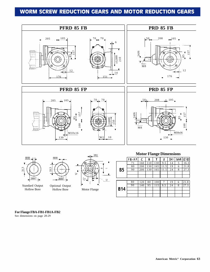
American Metric® Corporation 63
WORM SCREW REDUCTION GEARS AND MOTOR REDUCTION GEARS
PRD 85 FBPFRD 85 FB
PRD 85 FPPFRD 85 FP
205 105
176
1214
151
70 70
157
85
210
152H
8
650 208 105
176
12M8
157
8524J6
205 105
130M10x16
56.5
70 70
157
85
150
110H
8
1 0
50 208 105
130
M10x16
M8
157
8524J6
100
100
7 18090
160200200
110130130
130165165
9.511.511.5
141924
568
16.321.827.3
8090
120140
8095
100115
78.5
1924
68
21.827.3
8H8
30H7
33.3
8H8
28H7
31.3
For Flange FBA-FB1-FB1A-FB2See dimensions on page 28-29
Motor Flange Dimensions
Motor Flange
8H8
30H7
33.3
Optional OutputHollow Bore
8H8
28H7
31.3
Standard OutputHollow Bore
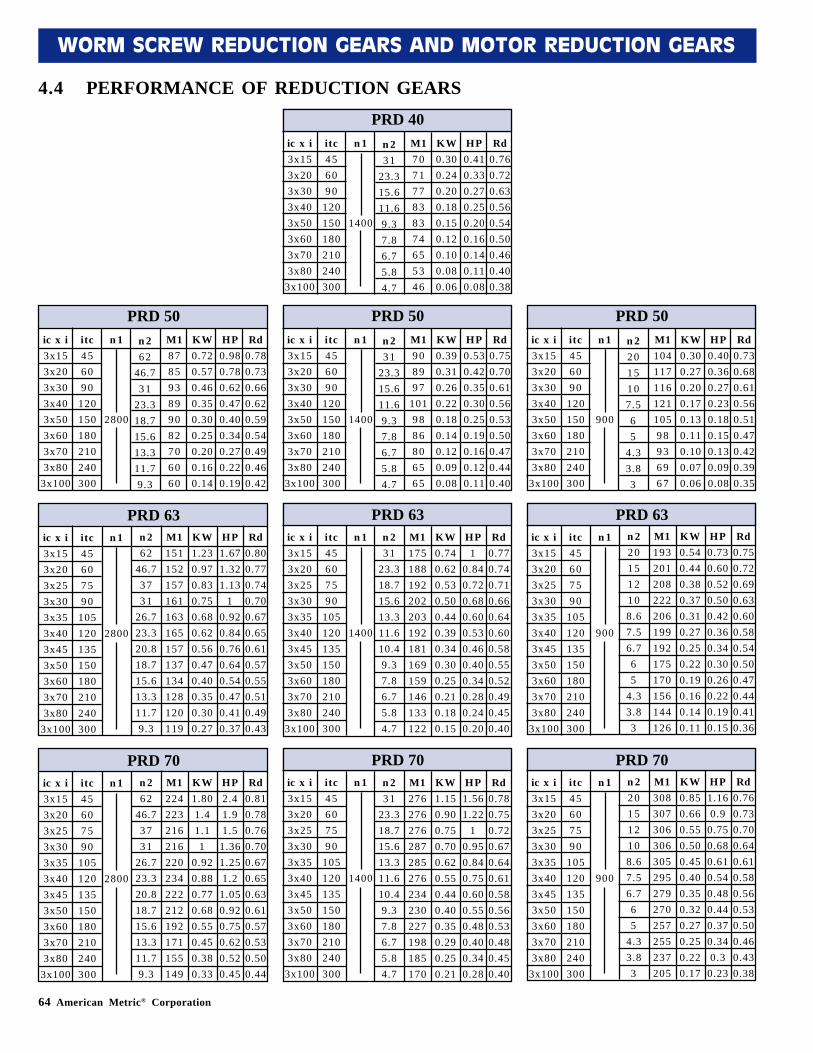
64 American Metric® Corporation
WORM SCREW REDUCTION GEARS AND MOTOR REDUCTION GEARS
4.4 PERFORMANCE OF REDUCTION GEARSPRD 40
itc456090
120150180210240300
n 1
1400
n 231
23.315.611.69.37.86.75.84.7
M1707177838374655346
KW0.300.240.200.180.150.120.100.080.06
HP0.410.330.270.250.200.160.140.110.08
Rd0.760.720.630.560.540.500.460.400.38
ic x i3x153x203x303x403x503x603x703x80
3x100
PRD 63itc45607590
105120135150180210240300
n 1
2800
n 262
46.73731
26.723.320.818.715.613.311.79.3
M1151152157161163165157137134128120119
KW1.230.970.830.750.680.620.560.470.400.350.300.27
HP1.671.321.13
10.920.840.760.640.540.470.410.37
Rd0.800.770.740.700.670.650.610.570.550.510.490.43
ic x i3x153x203x253x303x353x403x453x503x603x703x80
3x100
PRD 50itc456090
120150180210240300
n 1
2800
n 262
46.731
23.318.715.613.311.79.3
M1878593899082706060
KW0.720.570.460.350.300.250.200.160.14
HP0.980.780.620.470.400.340.270.220.19
Rd0.780.730.660.620.590.540.490.460.42
ic x i3x153x203x303x403x503x603x703x80
3x100
PRD 50itc456090
120150180210240300
n 1
1400
n 231
23.315.611.69.37.86.75.84.7
M1908997
1019886806565
KW0.390.310.260.220.180.140.120.090.08
HP0.530.420.350.300.250.190.160.120.11
Rd0.750.700.610.560.530.500.470.440.40
ic x i3x153x203x303x403x503x603x703x80
3x100
PRD 50itc456090
120150180210240300
n 1
900
n 22015107.565
4.33.83
M110411711612110598936967
KW0.300.270.200.170.130.110.100.070.06
HP0.400.360.270.230.180.150.130.090.08
Rd0.730.680.610.560.510.470.420.390.35
ic x i3x153x203x303x403x503x603x703x80
3x100
PRD 63itc45607590
105120135150180210240300
n 1
1400
n 231
23.318.715.613.311.610.49.37.86.75.84.7
M1175188192202203192181169159146133122
KW0.740.620.530.500.440.390.340.300.250.210.180.15
HP1
0.840.720.680.600.530.460.400.340.280.240.20
Rd0.770.740.710.660.640.600.580.550.520.490.450.40
ic x i3x153x203x253x303x353x403x453x503x603x703x80
3x100
PRD 63itc45607590
105120135150180210240300
n 1
900
n 2201512108.67.56.765
4.33.83
M1193201208222206199192175170156144126
KW0.540.440.380.370.310.270.250.220.190.160.140.11
HP0.730.600.520.500.420.360.340.300.260.220.190.15
Rd0.750.720.690.630.600.580.540.500.470.440.410.36
ic x i3x153x203x253x303x353x403x453x503x603x703x80
3x100
PRD 70itc45607590
105120135150180210240300
n 1
2800
n 262
46.73731
26.723.320.818.715.613.311.79.3
M1224223216216220234222212192171155149
KW1.801.41.11
0.920.880.770.680.550.450.380.33
HP2.41.91.5
1.361.251.2
1.050.920.750.620.520.45
Rd0.810.780.760.700.670.650.630.610.570.530.500.44
ic x i3x153x203x253x303x353x403x453x503x603x703x80
3x100
PRD 70itc45607590
105120135150180210240300
n 1
1400
n 231
23.318.715.613.311.610.49.37.86.75.84.7
M1276276276287285276234230227198185170
KW1.150.900.750.700.620.550.440.400.350.290.250.21
HP1.561.22
10.950.840.750.600.550.480.400.340.28
Rd0.780.750.720.670.640.610.580.560.530.480.450.40
ic x i3x153x203x253x303x353x403x453x503x603x703x80
3x100
PRD 70itc45607590
105120135150180210240300
n 1
900
n 2201512108.67.56.765
4.33.83
M1308307306306305295279270257255237205
KW0.850.660.550.500.450.400.350.320.270.250.220.17
HP1.160.9
0.750.680.610.540.480.440.370.340.3
0.23
Rd0.760.730.700.640.610.580.560.530.500.460.430.38
ic x i3x153x203x253x303x353x403x453x503x603x703x80
3x100
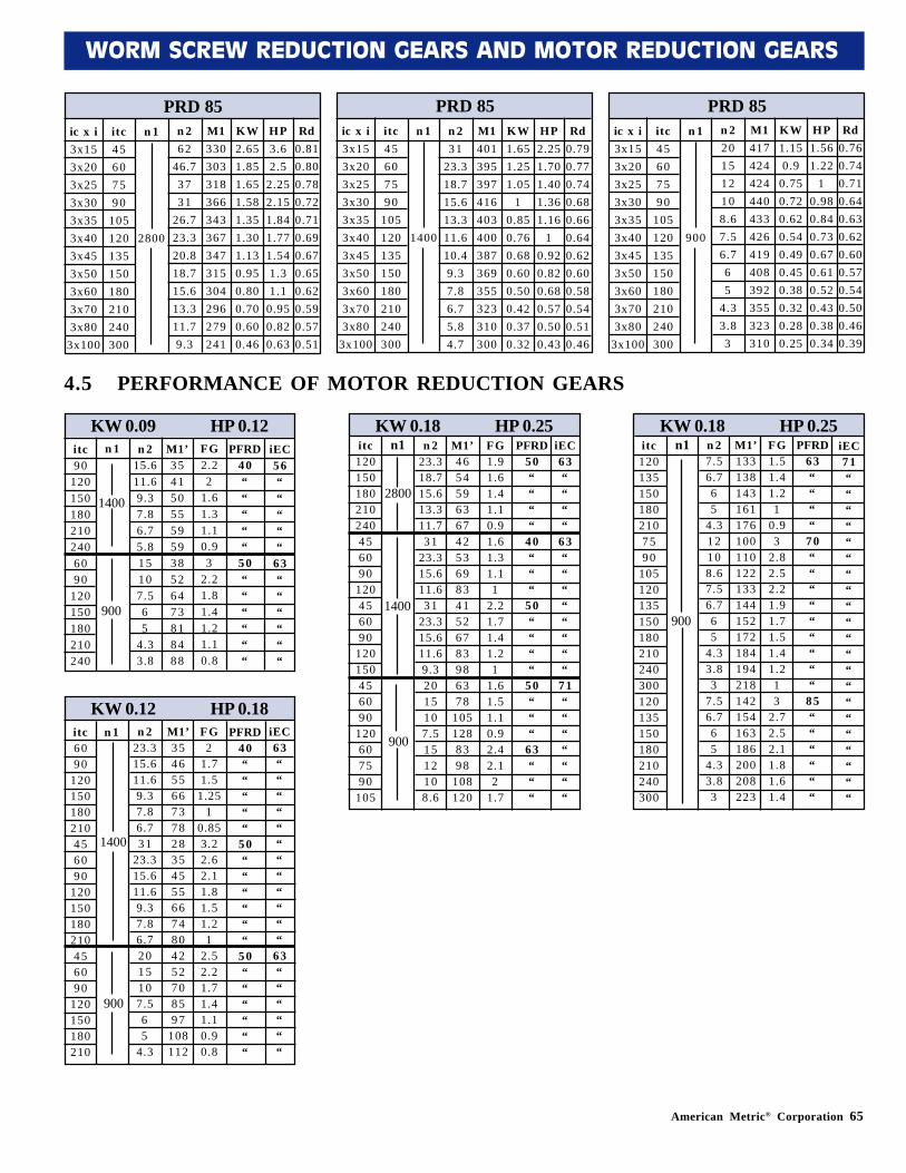
American Metric® Corporation 65
WORM SCREW REDUCTION GEARS AND MOTOR REDUCTION GEARS
itc120150180210240456090
120456090
120150456090
120607590
105
itc1201351501802107590
105120135150180210240300120135150180210240300
PRD 85itc45607590
105120135150180210240300
n 1
2800
n 262
46.73731
26.723.320.818.715.613.311.79.3
M1330303318366343367347315304296279241
KW2.651.851.651.581.351.301.130.950.800.700.600.46
HP3.62.5
2.252.151.841.771.541.31.1
0.950.820.63
Rd0.810.800.780.720.710.690.670.650.620.590.570.51
ic x i3x153x203x253x303x353x403x453x503x603x703x80
3x100
PRD 85itc45607590
105120135150180210240300
n 1
1400
n 231
23.318.715.613.311.610.49.37.86.75.84.7
M1401395397416403400387369355323310300
KW1.651.251.05
10.850.760.680.600.500.420.370.32
HP2.251.701.401.361.16
10.920.820.680.570.500.43
Rd0.790.770.740.680.660.640.620.600.580.540.510.46
ic x i3x153x203x253x303x353x403x453x503x603x703x80
3x100
PRD 85itc45607590
105120135150180210240300
n 1
900
n 2201512108.67.56.765
4.33.83
M1417424424440433426419408392355323310
KW1.150.9
0.750.720.620.540.490.450.380.320.280.25
HP1.561.22
10.980.840.730.670.610.520.430.380.34
Rd0.760.740.710.640.630.620.600.570.540.500.460.39
ic x i3x153x203x253x303x353x403x453x503x603x703x80
3x100
4.5 PERFORMANCE OF MOTOR REDUCTION GEARS
KW 0.09 HP 0.12itc90
1201501802102406090
120150180210240
n 1 n 215.611.69.37.86.75.815107.565
4.33.8
M1’35415055595938526473818488
FG2.22
1.61.31.10.93
2.21.81.41.21.10.8
PFRD40“““““
50““““““
iEC56“““““
63““““““
KW 0.12 HP 0.18itc6090
120150180210456090
120150180210456090
120150180210
n 1 n 223.315.611.69.37.86.731
23.315.611.69.37.86.72015107.565
4.3
M1’354655667378283545556674804252708597
108112
FG2
1.71.5
1.251
0.853.22.62.11.81.51.21
2.52.21.71.41.10.90.8
PFRD40“““““
50““““““
50““““““
iEC63““““““““““““
63““““““
KW 0.18 HP 0.25n1 n 2
7.56.765
4.312108.67.56.765
4.33.83
7.56.765
4.33.83
M1’133138143161176100110122133144152172184194218142154163186200208223
FG1.51.41.21
0.93
2.82.52.21.91.71.51.41.213
2.72.52.11.81.61.4
PFRD63““““
70“““““““““
85““““““
iEC71“““““““““““““““““““““
1400
900
1400
900900
KW 0.18 HP 0.25n1 n 2
23.318.715.613.311.731
23.315.611.631
23.315.611.69.32015107.51512108.6
M1’46545963674253698341526783986378
1051288398
108120
FG1.91.61.41.10.91.61.31.11
2.21.71.41.21
1.61.51.10.92.42.12
1.7
PFRD50““““
40“““
50““““
50“““
63“““
iEC63““““
63““““““““
71“““““““
2800
1400
900
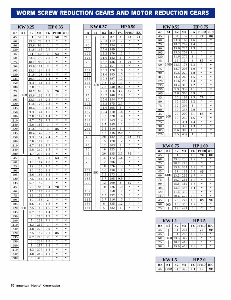
66 American Metric® Corporation
WORM SCREW REDUCTION GEARS AND MOTOR REDUCTION GEARS
KW 0.25 HP 0.35itc456090
12045607590
1051201351501807590
10512013515018021024012013515018021024030045607590
10512013545607590
105120135150180210240120135150180210240300
n 1 n 231
23.315.611.631
23.318.715.613.311.610.49.37.8
18.715.613.311.610.49.37.86.75.8
11.610.49.37.86.75.84.7201512108.67.56.7201512108.67.56.765
4.33.87.56.765
4.33.83
M1’577193
115597590
10111412313314115992
10211512513314416217118513214215417719221023389
11413715016618419291
116139153169185199210238255270197213227257277289310
FG1.61.21
0.93
2.52.12
1.81.61.41.213
2.82.52.21.81.61.41.213
2.72.42
1.71.51.32.11.81.51.51.21.11
3.42.62.22
1.81.61.41.31.11
0.92.12
1.81.51.31.11
PFRD50“““
63““““““““
70““““““““
85““““““
63““““““
70““““““““““
85““““““
iEC71““““““““““““““““““““““““““““
71““““““““““““““““““““““““
KW 0.55 HP 0.75n1 n 2
3123.318.715.613.311.631
23.318.715.613.311.610.49.37.820151210201512108.67.5
M1’132169202225252276134173208229260290313339390199255306336200259311336385434
FG2.11.61.41.31.113
2.31.91.81.51.41.21.10.91.51.21
0.92.11.61.41.31.11
PFRD70“““““
85““““““““
70“““
85“““““
iEC80““““““““““““““““““““““““
itc45607590
10512045607590
1051201351501804560759045607590
105120
1400
900
KW 0.75 HP 1.00n1 n 2
3123.318.715.631
23.318.715.613.311.610.4201512
M1’180230275307183236283312355395427272353424
FG1.51.21
0.92.21.71.41.31.11
0.91.51.21
PFRD70“““
85““““““
85““
iEC80““““““““““
90““
itc4560759045607590
105120135456075
1400
900
KW 0.37 HP 0.50itc45607590
1051207590
105120135150180607590
1051201351501802102403004560759045607590
1051201357590
105120135150180
n 1 n 231
23.318.715.613.311.618.715.613.311.610.49.37.8
23.318.715.613.311.610.49.37.86.75.84.720151210201512108.67.56.712108.67.56.765
M1’87
112134149170182136151170185197212240116140154175195210228263285310346132170203223135172206226250273295209226258292316335382
FG2
1.71.41.31.212
1.91.61.51.21.10.93.42.82.72.32
1.81.61.41.11
0.91.41.211
2.31.81.51.31.21.10.92
1.91.71.51.31.21
PFRD63“““““
70““““““
85““““““““““
63“““
70““““““
85““““““
1400
900
iEC71“““““““““““““““““““““““
80“““““““““““““““““
900
KW 1.1 HP 1.5n1 n 2
3131
23.318.715.6
M1’264268347416458
FG1
1.51.21
0.9
PFRD7085“““
iEC90““““
itc4545607590
1400
KW 1.5 HP 2.0n 231
M1’365
FG1.1
PFRD85
iEC90
itc45
n 11400
1400
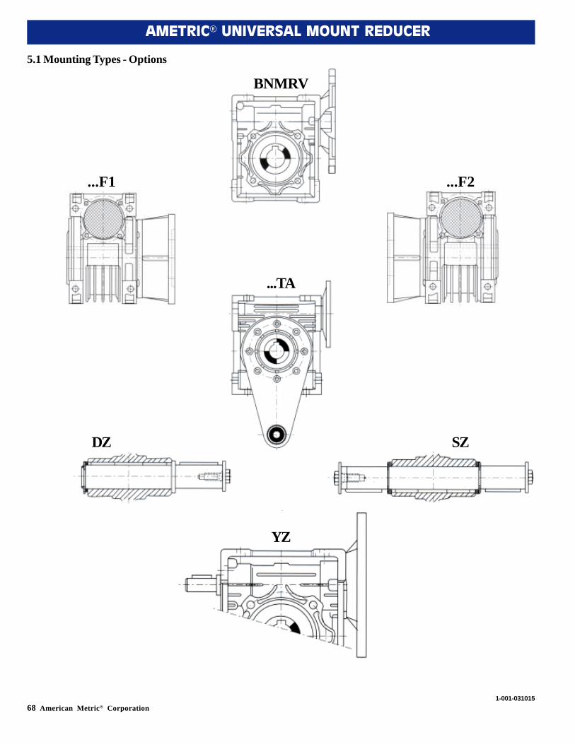
68 American Metric® Corporation
AMETRIC® UNIVERSAL MOUNT REDUCER
5.1 Mounting Types - Options
1-001-031015
BNMRV
...TA
YZ
...F1
DZ
...F2
SZ
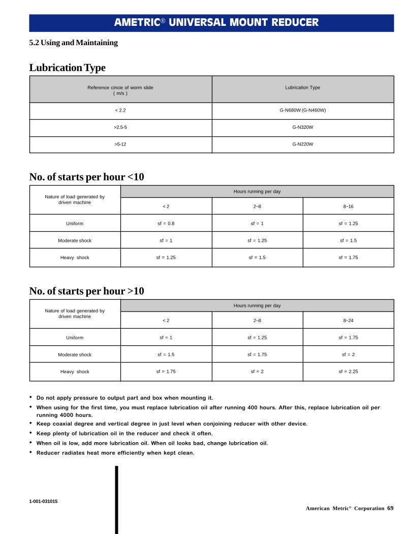
American Metric® Corporation 69
AMETRIC® UNIVERSAL MOUNT REDUCER
5.2 Using and Maintaining
1-001-031015
Reference cincie of worm slide( m/s )
< 2.2
>2.5-5
>5-12
Lubrication Type
G-N680W (G-N460W)
G-N320W
G-N220W
Lubrication Type
Nature of load generated bydriven machine
< 2
sf = 0.8
sf = 1
sf = 1.25
Hours running per day
2~8
sf = 1
sf = 1.25
sf = 1.5
8~16
sf = 1.25
sf = 1.5
sf = 1.75
Uniform
Moderate shock
Heavy shock
No. of starts per hour <10
Nature of load generated bydriven machine
< 2
sf = 1
sf = 1.5
sf = 1.75
Hours running per day
2~8
sf = 1.25
sf = 1.75
sf = 2
8~24
sf = 1.75
sf = 2
sf = 2.25
Uniform
Moderate shock
Heavy shock
No. of starts per hour >10
• Do not apply pressure to output part and box when mounting it.
• When using for the first time, you must replace lubrication oil after running 400 hours. After this, replace lubrication oil perrunning 4000 hours.
• Keep coaxial degree and vertical degree in just level when conjoining reducer with other device.
• Keep plenty of lubrication oil in the reducer and check it often.
• When oil is low, add more lubrication oil. When oil looks bad, change lubrication oil.
• Reducer radiates heat more efficiently when kept clean.
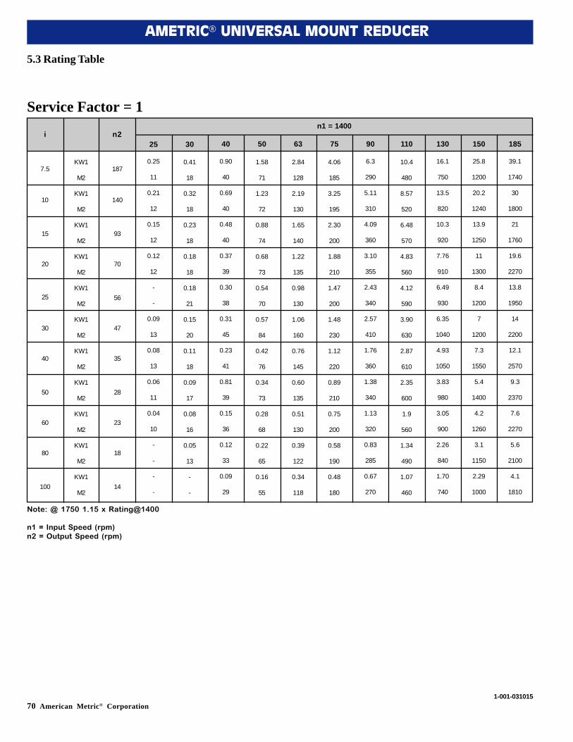
70 American Metric® Corporation
AMETRIC® UNIVERSAL MOUNT REDUCER
5.3 Rating Table
i n225 30 40 50 63 75 90 110 130 150 185
n1 = 1400
0.25
11
0.21
12
0.15
12
0.12
12
-
-
0.09
13
0.08
13
0.06
11
0.04
10
-
-
-
-
0.41
18
0.32
18
0.23
18
0.18
18
0.18
21
0.15
20
0.11
18
0.09
17
0.08
16
0.05
13
-
-
0.90
40
0.69
40
0.48
40
0.37
39
0.30
38
0.31
45
0.23
41
0.81
39
0.15
36
0.12
33
0.09
29
1.58
71
1.23
72
0.88
74
0.68
73
0.54
70
0.57
84
0.42
76
0.34
73
0.28
68
0.22
65
0.16
55
2.84
128
2.19
130
1.65
140
1.22
135
0.98
130
1.06
160
0.76
145
0.60
135
0.51
130
0.39
122
0.34
118
4.06
185
3.25
195
2.30
200
1.88
210
1.47
200
1.48
230
1.12
220
0.89
210
0.75
200
0.58
190
0.48
180
6.3
290
5.11
310
4.09
360
3.10
355
2.43
340
2.57
410
1.76
360
1.38
340
1.13
320
0.83
285
0.67
270
10.4
480
8.57
520
6.48
570
4.83
560
4.12
590
3.90
630
2.87
610
2.35
600
1.9
560
1.34
490
1.07
460
16.1
750
13.5
820
10.3
920
7.76
910
6.49
930
6.35
1040
4.93
1050
3.83
980
3.05
900
2.26
840
1.70
740
25.8
1200
20.2
1240
13.9
1250
11
1300
8.4
1200
7
1200
7.3
1550
5.4
1400
4.2
1260
3.1
1150
2.29
1000
39.1
1740
30
1800
21
1760
19.6
2270
13.8
1950
14
2200
12.1
2570
9.3
2370
7.6
2270
5.6
2100
4.1
1810
KW1
M2
KW1
M2
KW1
M2
KW1
M2
KW1
M2
KW1
M2
KW1
M2
KW1
M2
KW1
M2
KW1
M2
KW1
M2
Service Factor = 1
7.5
10
15
20
25
30
40
50
60
80
100
187
140
93
70
56
47
35
28
23
18
14
1-001-031015
Note: @ 1750 1.15 x Rating@1400
n1 = Input Speed (rpm)n2 = Output Speed (rpm)
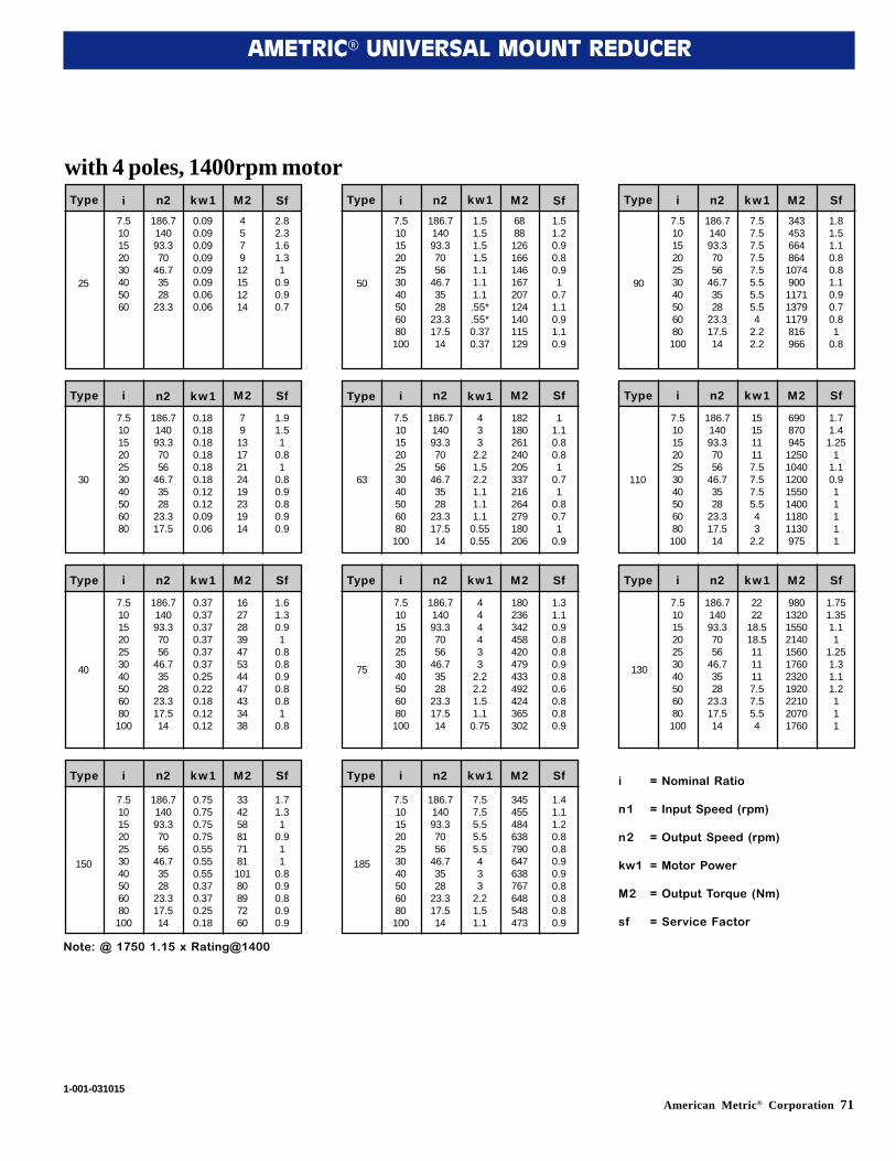
American Metric® Corporation 71
AMETRIC® UNIVERSAL MOUNT REDUCER
7.5101520253040506080100
7.5101520253040506080100
7.5101520253040506080100
7.5101520253040506080100
186.714093.37056
46.73528
23.317.514
186.714093.37056
46.73528
23.317.514
186.714093.37056
46.73528
23.317.514
186.714093.37056
46.73528
23.317.514
1.51.51.51.51.11.11.1.55*.55*0.370.37
433
2.21.52.21.11.11.10.550.55
444433
2.22.21.51.10.75
7.57.55.55.55.5433
2.21.51.1
6888126166146167207124140115129
182180261240205337216264279180206
180236342458420479433492424365302
345455484638790647638767648548473
1.51.20.90.80.91
0.71.10.91.10.9
11.10.80.81
0.71
0.80.71
0.9
1.31.10.90.80.80.90.80.60.80.80.9
1.41.11.20.80.80.90.90.80.80.80.9
7.510152030405060
7.5101520253040506080
7.5101520253040506080100
7.5101520253040506080100
186.714093.370
46.73528
23.3
186.714093.37056
46.73528
23.317.5
186.714093.37056
46.73528
23.317.514
186.714093.37056
46.73528
23.317.514
0.090.090.090.090.090.090.060.06
0.180.180.180.180.180.180.120.120.090.06
0.370.370.370.370.370.370.250.220.180.120.12
0.750.750.750.750.550.550.550.370.370.250.18
457912151214
791317212419231914
1627283947534447433438
33425881718110180897260
2.82.31.61.31
0.90.90.7
1.91.51
0.81
0.80.90.80.90.9
1.61.30.91
0.80.80.90.80.81
0.8
1.71.31
0.911
0.80.90.80.90.9
7.5101520253040506080100
7.5101520253040506080100
7.5101520253040506080100
186.714093.37056
46.73528
23.317.514
186.714093.37056
46.73528
23.317.514
186.714093.37056
46.73528
23.317.514
7.57.57.57.57.55.55.55.54
2.22.2
151511117.57.57.55.543
2.2
2222
18.518.51111117.57.55.54
3434536648641074900117113791179816966
6908709451250104012001550140011801130975
9801320155021401560176023201920221020701760
1.81.51.10.80.81.10.90.70.81
0.8
1.71.41.25
11.10.911111
1.751.351.11
1.251.31.11.2111
Type i n2 kw1 M2 Sf Type i n2 kw1 M2 Sf Type i n2 kw1 M2 Sf
Type i n2 kw1 M2 Sf Type i n2 kw1 M2 Sf Type i n2 kw1 M2 Sf
Type i n2 kw1 M2 Sf Type i n2 kw1 M2 Sf Type i n2 kw1 M2 Sf
Type i n2 kw1 M2 Sf Type i n2 kw1 M2 Sf i
n1
n2
kw1
M2
sf
= Nominal Ratio
= Input Speed (rpm)
= Output Speed (rpm)
= Motor Power
= Output Torque (Nm)
= Service Factor
with 4 poles, 1400rpm motor
1-001-031015
25
30
40
150
50
63
75
185
90
110
130
Note: @ 1750 1.15 x Rating@1400
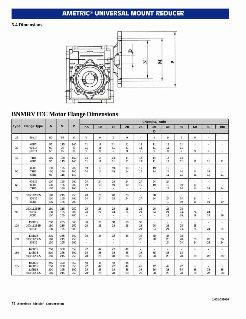
72 American Metric® Corporation
AMETRIC® UNIVERSAL MOUNT REDUCER
5.4 Dimensions
56B14
63B563B1456B14
71B563B5
80B571B563B5
90B3580B571B5
100/112B3590B3580B5
100/112B3590B3580B5
132B35100/112B35
90B35
132B35100/112B35
90B35
160B35132B35
100/112B35
180B35160B35132B35
100/112B35
50
956050
11095
13011095
130130110
180130130
180130130
230180130
230180130
250230180
250250230180
65
1157565
130115
165130115
165165130
215165165
215165165
265215165
265215165
300265215
300300265215
80
1409080
160140
200160140
200200160
250200200
250200200
300250200
300250200
350300250
350350300250
9
11119
1411
1914-
2419-
2824-
2824-
3828-
38--
423828
48423828
9
11119
1411
1914-
2419-
2824-
2824-
3828-
38--
423828
48423828
9
11119
1411
1914-
2419-
2824-
2824-
3828-
38--
423828
48423828
9
11119
1411
1914-
2419-
2824-
2824-
3828-
38--
423828
48423828
-
11119
1411
1914-
2419-
-24-
2824-
382824
3828-
-3828
-423828
9
11119
1411
1914-
2419-
2824-
2824-
-2824
3828-
-3828
-423828
9
11119
1411
191411
241914
-2419
282419
-2824
382824
-3828
-423828
9
11119
1411
-1411
-1914
-2419
282419
-2824
382824
-3828
-423828
9
--9
-11
-1411
-1914
-2419
-2419
-2824
-2824
--
28
--
3828
-
--9
-11
-1411
--
14
--
19
-2419
--
24
-2824
--
28
--
3828
-
---
-11
--
11
--
14
--
19
--
19
--
24
-2824
--
28
--
3828
25
30
40
50
63
75
90
110
130
150
185
Type Flange type N M P 7.5 10 15 20 25 30 40 50 60 80 100D
i/Nominal ratio
BNMRV IEC Motor Flange Dimensions
D
N M P
1-001-031016
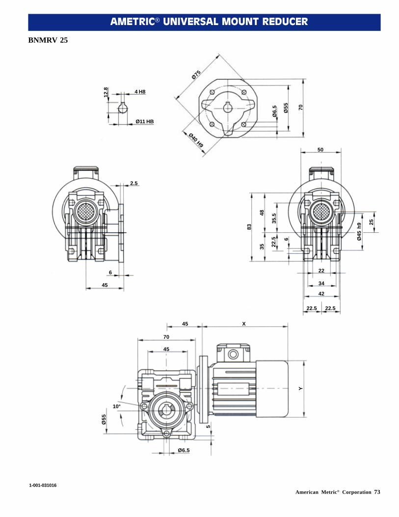
American Metric® Corporation 73
AMETRIC® UNIVERSAL MOUNT REDUCER
BNMRV 25
12.8 4 H8
Ø11 HB
Ø75
Ø40 H9
Ø6.
5
Ø55 70
2.5
6
45
50
83
4835
35.5
22.5 6 Ø
45 h
9 25
22
34
42
22.5 22.5
X45
70
45
Y
5
Ø6.5
Ø55
10°
1-001-031016
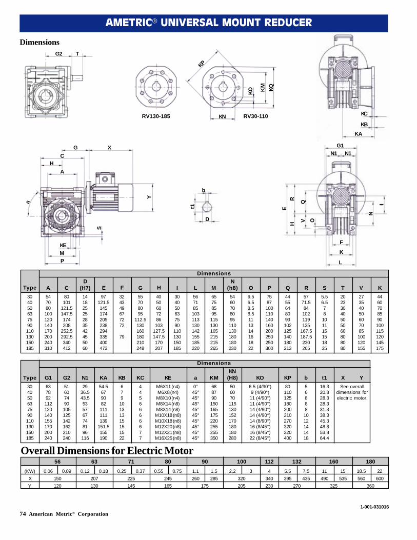
74 American Metric® Corporation
AMETRIC® UNIVERSAL MOUNT REDUCER
Dimensions
304050637590110130150185
547080100120140170200240310
80101
121.5147.5174208
252.5292.5340412
14182525283542455060
97121.5145174205238294335400472
324349677272
79
55708095
112.5130160180210248
4050607286103
127.5147.5170207
304050637590110130150185
567185103113130142155185220
65758595115130165215215265
5460708095110130180180230
6.56.58.58.5111314161822
7587100110140160200250250300
4455648093102125140180213
5771.584102119135
167.5187.5230265
5.56.578101115151825
20233040505060808080
27354050607085100120155
4460708590100115120145175
Type A CD
(H7) E F G H I L MN
(h8) O P Q R S T V K
Dimensions
304050637590110130150185
637892112120140155170200240
51607490105125142162210240
2936.543.5535767748196116
54.5679082111111139
151.5155190
67910131315151522
4456666677
M6X11 (n4)M6X8 (n4)M8X10 (n4)M8X14 (n8)M8X14 (n8)M10X18 (n8)M10X18 (n8)M12X20 (n8)M12X21 (n8)M16X25 (n8)
0°45°45°45°45°45°45°45°45°45°
688790150165175220255255350
506070115130152170180180280
6.5 (4/90°)9 (4/90°)11 (4/90°)11 (4/90°)14 (4/90°)14 (4/90°)14 (8/90°)16 (8/45°)16 (8/45°)22 (8/45°)
80110125180200210270320320400
568881012141418
16.320.828.328.331.338.345.348.853.864.4
See overalldimensions forelectric motor.
Type G1 G2 N1 KA KB KC KE a KMKN
(H8) KO KP b t1 X Y
Dimensions
(KW) 0.06 0.09 0.12 0.18 0.25 0.37 0.55 0.75 1.1 1.5 2.2 3 4 5.5 7.5 11 15 18.5 22X 150 207 225 245 260 285 320 340 395 435 490 535 560 600Y 120 130 145 165 175 205 230 270 325 360
56 63 71 80 90 100 112 132 160 180Overall Dimensions for Electric Motor
G2 T
RV130-185
KP
KN
KO KM KQ
RV30-110
G XC
HA
Y
a
KEMP
S
bt1
D
G1N1 N1
F
K
L
ER
H
QV O
N
I
1-001-031016
KC
KBKA
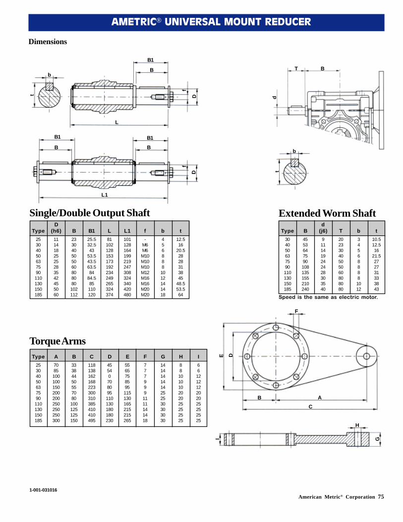
American Metric® Corporation 75
AMETRIC® UNIVERSAL MOUNT REDUCER
Dimensions
25304050637590110130150185
1114182525283542455060
233040505060808080102112
25.532.543
53.543.563.584
84.585110120
81102128153173192234249265324374
101128164199219247308324340420480
-M6M6M10M10M10M12M16M16M20M20
4568881012141418
12.516
20.52828313845
48.553.564
TypeD
(h6) B B1 L L1 f b t10.512.516
21.5272731333843
345688881012
20233040505060808080
9111419242428303540
4553647590108135155210240
304050637590110130150185
Type Bd
(j6) T b t
25304050637590110130150185
7085100100150200200250250250300
33384450557080100125125150
118138162168223300310385410410495
45540708095110130180180230
5565758595115130165215215265
7779991111141418
1414141414252530303030
88101010202025252525
66121212202025252525
Type A B C D E F G H I
b
t
B1
B
f
D
L
B1
B
B1
B
D
f
L1
b
t
BT
d
F
E D
B AC
H
GISingle/Double Output Shaft
Torque Arms
Extended Worm Shaft
Speed is the same as electric motor.
1-001-031016
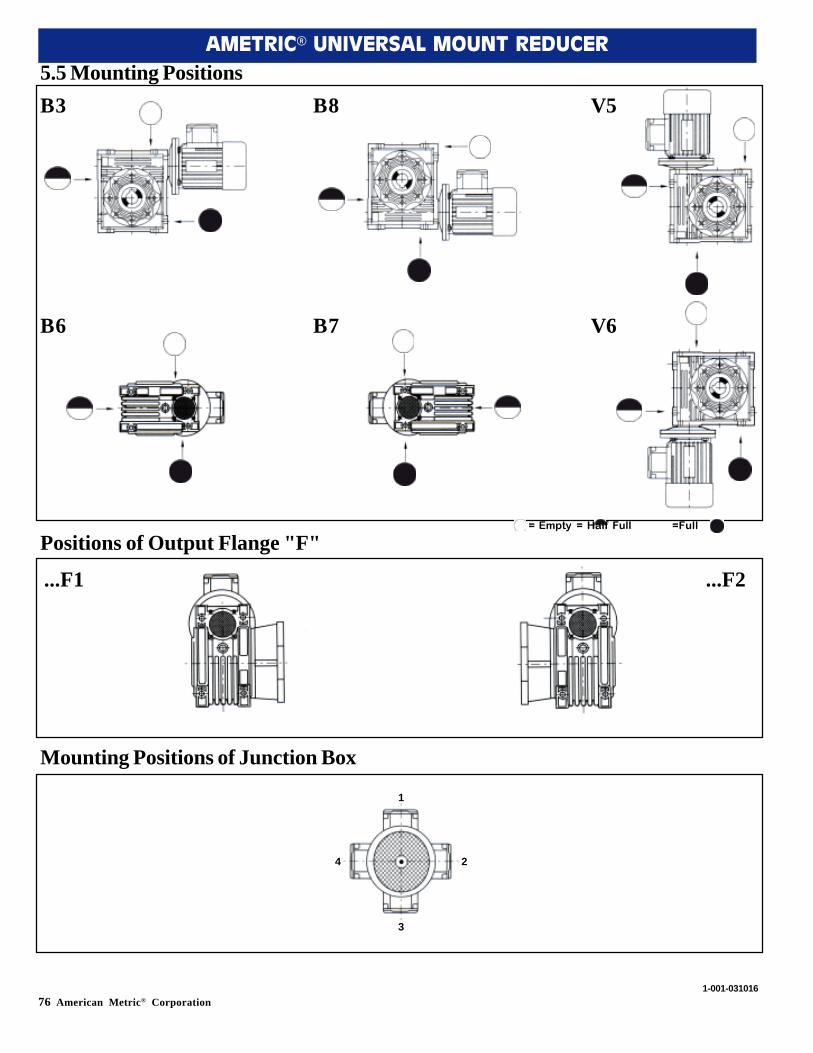
76 American Metric® Corporation
AMETRIC® UNIVERSAL MOUNT REDUCER
5.5 Mounting Positions
Positions of Output Flange "F"
Mounting Positions of Junction Box
= Empty = Half Full =Full
B3 B8 V5
B6 B7 V6
...F1 ...F2
1
2
3
4
1-001-031016