Embed Size (px)
Citation preview
2
Eever since Elecon's inception 48 years ago, they have strived to reach new frontiers oftechnical excellence. From a modest start in manufacturing material handling equipment namelyELEVATORS & CONVEYORS in 1951, Elecon graduated to the manufacture of gear boxes(initially for captive use) in 1963. Today, Elecon's name become synonymous with high qualitygear and material handling equipment in India.
Elecon had set up a separate Gear Division in 1976. This division has a capacity of producingmore than 25,000 gear unit yearly, out of which 90% share for worm speed reduction gear unitsand remaining share in helical speed reduction gear unit. The gear units are workingsatisfactorily in cement, chemical, plastic, paper, power generation, sugar, textile, thermal plantindustries.
Elecon have a wide range of worm, parallel shaft and right angle helical – spiral bevel speedreduction gear units.
Elecon have many firsts to their credit. In the eighties, they were the first to introduce case-hardenedand ground gear technology in India and the modular design concept for gear manufacture inIndia, as a result of which economical mass production and comprehensive maintenance ofcomponent stocks were made possible.
The latest additions to their production line are planetary gear boxes for marine and otherapplications which have already been delivered for use on the off-shore patrol vessels of theIndian Coast Guard. These are very compact, high precision gear boxes, capable oftransmitting up to 23,000 KW of power.
For a forward-looking organisation like Elecon, modernisation is the watchword. That is preciselywhy they continuously update their production technology through frequent capital andinfrastructural investments. Elecon have geared themselves for tomorrow by setting up one ofthe largest EDP centres in the Indian Engineering Industry. More than 85% of their machineryis computer controlled, ensuring a high degree of precision in the manufacture, design andtesting of gear components. Apart from a large concentration of computerised numericallycontrolled (CNC) machines, they have flexible machining systems, a battery of modern qualitycontrol equipments for checking gear component's various parameters and geometry, on-linecomputerised inventory control, production planning and execution programmes. All this hasresulted in Elecon's Gear Division being the most modern in the country – a fact that isunanimously acknowledged throughout the industry. Just as it is acknowledged by clients thatElecon, despite their stature and focus on modernisation, have not lost sight of their primarygoal - customer satisfaction.
ISO – 9001 for Elecon Gear Division
In November 1994, the RW – TUV Germany has accredited that Elecon Gear Division QualityManagement System confirms to the internationally accepted ISO 9001 standards. Thiscertificate covers Quality Assurance in Design and Development, Production, Installation andService of mechanical transmission products like Worm, Helical and special gear units, Fluid ,Geared and Flexible couplings and Accessories.
3
SFU
SFO SFV
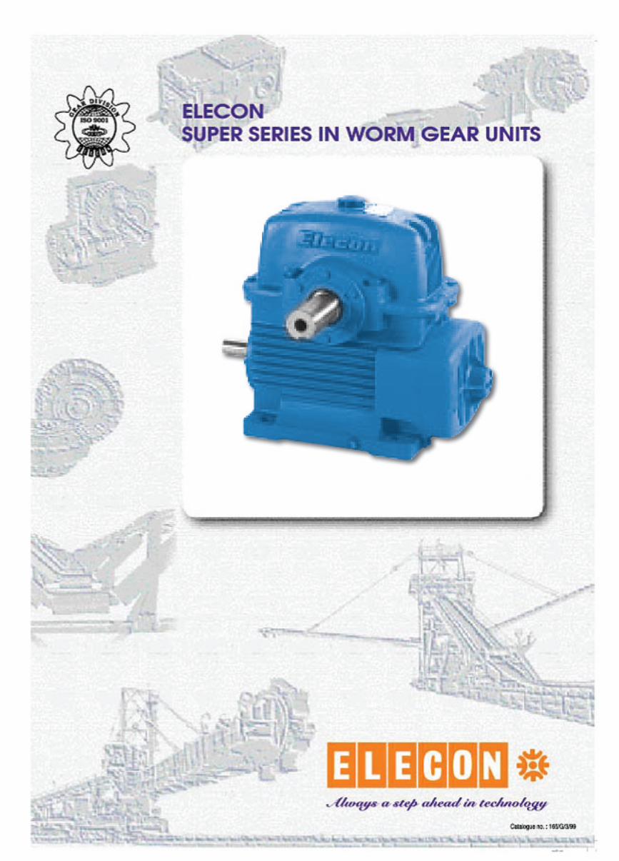
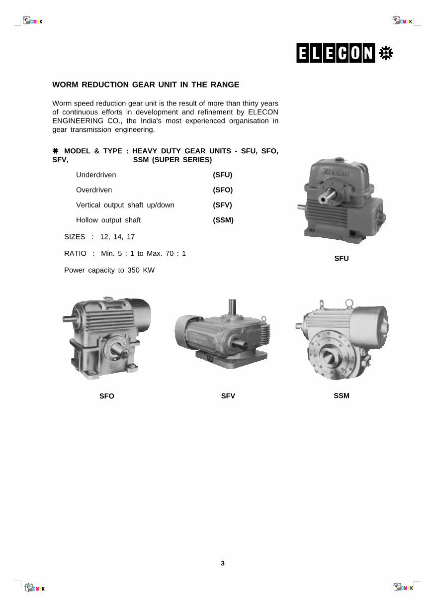
WORM REDUCTION GEAR UNIT IN THE RANGE
Worm speed reduction gear unit is the result of more than thirty yearsof continuous efforts in development and refinement by ELECONENGINEERING CO., the India's most experienced organisation ingear transmission engineering.
✷✷✷✷✷ MODEL & TYPE : HEAVY DUTY GEAR UNITS - SFU, SFO,SFV, SSM (SUPER SERIES)
Underdriven (SFU)
Overdriven (SFO)
Vertical output shaft up/down (SFV)
Hollow output shaft (SSM)
SIZES : 12, 14, 17
RATIO : Min. 5 : 1 to Max. 70 : 1
Power capacity to 350 KW
SSM
4
SUPER SERIES IN WORM GEAR UNITSSPECIFICATIONS
GENERAL
Elecon single reduction gear units are the result ofmany years of experience. Completely re-designed gearcase with liberal ribbing increases heat dissipating area,streamlined sump carrying more oil and larger capacityof fan enhance the thermal rating of the gearbox. Allthis means that the continuous load carrying capacity isincreased without substantial rise in temperature.
No more opening of gearbox for hand changing, justreplace the fan and fancowl from one end to other endof worm shaft.
DESIGN STANDARDS
Wherever applicable, British as well as Indian standardsare used. Worm conforms to casehardening alloy steel,worm wheel conforms to phosphor-bronze PB2-C asper British Standard B.S. 1400, while gear caseconforms to C. I. grade FG 220 and for heavy duty FG250, Indian Standard I.S. 210.
GEAR CASE
Gear case is of streamlined design, rugged inconstruction, made of close-grain cast iron. It iscompletely oil-tight, dust-proof and capable of beinginstalled in the open without a separate cover. Thefaces and bores are accurately bored and machined onlatest precision machines to ensure perfect alignmentand interchangeability.
WORM/WORM WHEEL
The worm is made of case-hardening alloy steel,carburised, ground and polished and is integral with theshaft. Bearing journals are accurately ground. Wormwheel is made of centrifuglly cast phosphor-bronzerims, shrink fitted and brazed with C.I. centres.
Worms are generated on special-purpose worm millingmachines, gas carburised and ground on automaticwork grinders.
Worm wheels are hobbed on precision hobbingmachines with high accuracy hobs. Each and everywheel is checked to match with the master worms toensure complete interchangeability.
Right-hand threads are provided, unless otherwisespecified.
BEARINGS
The worms and worm wheels are supported on ball orroller anti-friction bearings of ample margin of safety toallow adequate journal as well as thrust loads. Overhungloads arising out of sprocket or pinion drive are generallypermissible because the gear case and bearings are
designed for this duty. However, complete details shouldbe given to us for confirmation. In cases of heavyoverhung loads, an extra roller bearing can be provided.
WHEEL SHAFT
The wheel shaft is made of high tensile carbon steel.It is of large diameter to carry the torsional as well asbending loads which may be induced by overhung drives.
LUBRICATION
Lubrication to gears and bearings is by splash of oilfrom the sump. Thus, no special care is requiredexcept for the occasional topping up of the oil to therequired level. A large oil filler-cum-breather andinspection cover is provided together with a drainplug and ventilator. Neoprene lip-type oil seals are fittedon input and output shaft.
For very low input speed below 50 rpm. and heavy loadsin sizes larger than 14" size forced lubrication is required.In such cases Elecon must be consulted.
COOLING
Air cooling is effected by means of standard polypro-pylene or metal fans which direct a continuous flow ofair over the ribbed surface of the gear unit. The fan isdesigned to operate in both direction of rotation, and isso arranged in conjunction with the ribbing on the gearunit as to allow maximum heat dissipation.
HOLDBACK
Elecon Sprag type holdback can be fitted on all sizes ofgears to prevent reverse rotation. In cases where hold-back is requied, the direction of rotation of the shaftshould be mentioned.
POWER RATINGS
The ratings indicated in the catalogue holds good for 12hours of continuous running under uniform load beingdriven by electric motor. They give minimum gear life of26,000 hours, subject to limitation of maximum oiltemperature of 100oC under full load, 20oC ambient.
OVERLOADS
All the components of the reduction gears are sodesigned that they can withstand.
100 per cent overload for 15 seconds
50 per cent overload for one minute
40 per cent overload for 30 minutes and
25 per cent overload for two hours.*
*
*
*
5
Super NU Series MODULAR WORM GEARUNIVERSAL MOUNTING
Further to successful launching of ELECON 'NU' Modular worm gearboxes, "SUPER NU" series is onestep ahead in WORM GEAR TECHNOLOGY.
A combination of present-day concepts, analytical calculations with the help of CAD (Computer AidedDesign) carried out on single part use of very latest CNC machine tools plus systematic checks onmaterials and workmanship, give this series of gearboxes a marked degree of reliability.
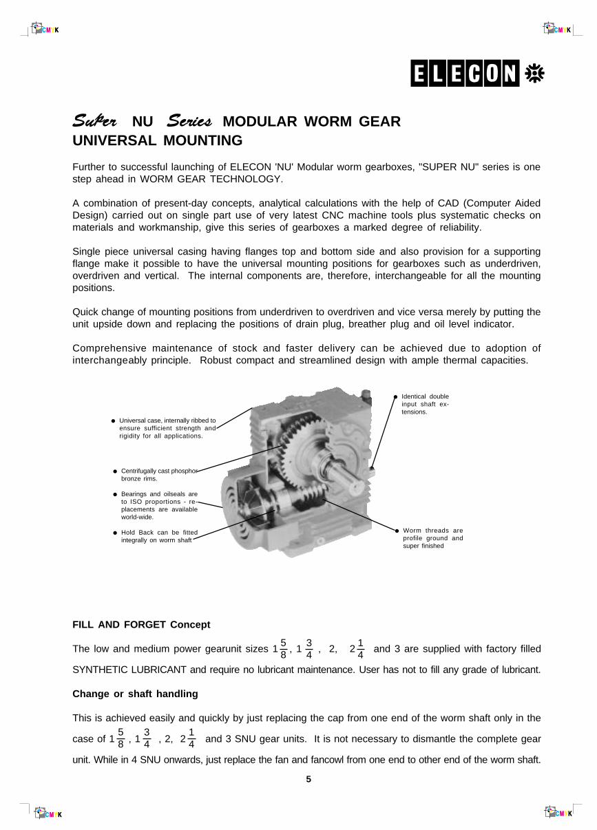
Single piece universal casing having flanges top and bottom side and also provision for a supportingflange make it possible to have the universal mounting positions for gearboxes such as underdriven,overdriven and vertical. The internal components are, therefore, interchangeable for all the mountingpositions.
Quick change of mounting positions from underdriven to overdriven and vice versa merely by putting theunit upside down and replacing the positions of drain plug, breather plug and oil level indicator.
Comprehensive maintenance of stock and faster delivery can be achieved due to adoption ofinterchangeably principle. Robust compact and streamlined design with ample thermal capacities.
● Universal case, internally ribbed toensure sufficient strength andrigidity for all applications.
● Centrifugally cast phosphorbronze rims.
● Bearings and oilseals areto ISO proportions - re-placements are availableworld-wide.
● Hold Back can be fittedintegrally on worm shaft
● Identical doubleinput shaft ex-tensions.
● Worm threads areprofile ground andsuper finished
FILL AND FORGET Concept
The low and medium power gearunit sizes 1 , 1 , 2, 2 and 3 are supplied with factory filled
SYNTHETIC LUBRICANT and require no lubricant maintenance. User has not to fill any grade of lubricant.
Change or shaft handling
This is achieved easily and quickly by just replacing the cap from one end of the worm shaft only in the
case of 1 , 1 , 2, 2 and 3 SNU gear units. It is not necessary to dismantle the complete gear
unit. While in 4 SNU onwards, just replace the fan and fancowl from one end to other end of the worm shaft.
58
34
14
58
34
14
6
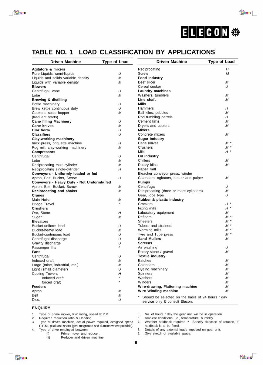
Driven Machine Type of Load
Agitators & mixersPure Liquids, semi-liquids ULiquids and solids variable density MLiquids with variable density MBlowersCentrifugal, vane ULobe MBrewing & distillingBottle machinery UBrew kettle continuous duty UCookers, scale hopper M(frequent starts)Cane filling Machinery UCane knives MClarifiers• UClassifiers UClay-working machinerybrick press, briquette machine HPug mill, clay-working machinery MCompressorsCentrifugal ULobe MReciprocating multi-cylinder MReciprocating single-cylinder HConveyors - Uniformly loaded or fedApron, Belt, Bucket, Screw UConveyors - Heavy Duty - Not Uniformly fedApron, Belt, Bucket, Screw MReciprocating and shaker MCranesMain Hoist MBridge Travel *CrushersOre, Stone HSugar MElevatorsBucket-uniform load UBucket-heavy load MBucket-continuous load UCentrifugal discharge UGravity discharge UPassenger lifts *FansCentrifugal UInduced draft MLarge (mine, industrial, etc.) MLight (small diameter) UCooling Towers H
Induced draft *forced draft *
FeedersApron MBelt MDisc. U
TABLE NO. 1 LOAD CLASSIFICATION BY APPLICATIONS
ENQUIRY
1. Type of prime mover, KW rating, speed R.P.M.2. Required reduction ratio & Handing.3. Type of driven machine, actual power required, designed speed
R.P.M., peak and shock (give magnitude and duration where possible).4. Type of drive employed between
(i) Prime mover and reducer.(ii) Reducer and driven machine
5. No. of hours / day the gear unit will be in operation.6. Ambient conditions, i.e., temperature, humidity.7. Whether holdback required ? Specify direction of rotation, if
holdback is to be fitted.8. Details of any external loads imposed on gear unit.9. Give sketch of available space.
Driven Machine Type of Load
Reciprocating HScrew MFood IndustryBeef slicer MCereal cooker ULaundry machinesWashers, tumblers MLine shaft MMillsHammers HBall kilns, pebbles MRod tumbling barrels HCement kilns MDryers and coolers MMixersConcrete mixers MSugar industryCane knives M *Crushers M *Mills H *Oil industryChillers MRotary kilns MPaper millBleacher conveyor press, winderCalendars, agitators, beater and pulper MPumpsCentrifugal UReciprocating (three or more cylinders) MGear, lobe type URubber & plastic industryCrackers H *Fixing mills H *Laboratory equipment MRefiners M *Sheeters M *Tubers and strainers M *Warming mills M *Tyre and Tube press M *Sand Mullers MScreensAir washing URotary-stone / gravel MTextile industryBatches MCalendars MDyeing machinery MSpinners MWashers MWinders MWire-drawing, Flattening machine MWire Winding machine M
* Should be selected on the basis of 24 hours / day service only & consult Elecon.
7
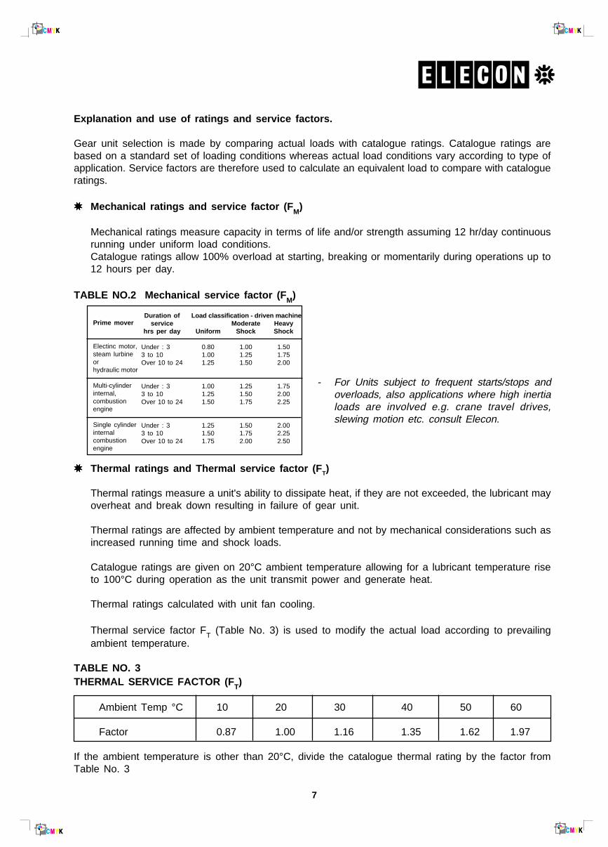
Explanation and use of ratings and service factors.
Gear unit selection is made by comparing actual loads with catalogue ratings. Catalogue ratings arebased on a standard set of loading conditions whereas actual load conditions vary according to type ofapplication. Service factors are therefore used to calculate an equivalent load to compare with catalogueratings.
✷✷✷✷✷ Mechanical ratings and service factor (F M)
Mechanical ratings measure capacity in terms of life and/or strength assuming 12 hr/day continuousrunning under uniform load conditions.Catalogue ratings allow 100% overload at starting, breaking or momentarily during operations up to12 hours per day.
TABLE NO.2 Mechanical service factor (F M)
- For Units subject to frequent starts/stops andoverloads, also applications where high inertialoads are involved e.g. crane travel drives,slewing motion etc. consult Elecon.
✷✷✷✷✷ Thermal ratings and Thermal service factor (F T)
Thermal ratings measure a unit's ability to dissipate heat, if they are not exceeded, the lubricant mayoverheat and break down resulting in failure of gear unit.
Thermal ratings are affected by ambient temperature and not by mechanical considerations such asincreased running time and shock loads.
Catalogue ratings are given on 20°C ambient temperature allowing for a lubricant temperature riseto 100°C during operation as the unit transmit power and generate heat.
Thermal ratings calculated with unit fan cooling.
Thermal service factor FT (Table No. 3) is used to modify the actual load according to prevailingambient temperature.
TABLE NO. 3THERMAL SERVICE FACTOR (F T)
Ambient Temp °C 10 20 30 40 50 60
Factor 0.87 1.00 1.16 1.35 1.62 1.97
If the ambient temperature is other than 20°C, divide the catalogue thermal rating by the factor fromTable No. 3
Load classification - driven machineModerate Heavy
Uniform Shock Shock
0.80 1.00 1.501.00 1.25 1.751.25 1.50 2.00
1.00 1.25 1.751.25 1.50 2.001.50 1.75 2.25
1.25 1.50 2.001.50 1.75 2.251.75 2.00 2.50
Prime mover
Electinc motor,steam lurbineorhydraulic motor
Multi-cylinderinternal,combustionengine
Single cylinderinternalcombustionengine
Duration ofservice
hrs per day
Under : 33 to 10Over 10 to 24
Under : 33 to 10Over 10 to 24
Under : 33 to 10Over 10 to 24
8
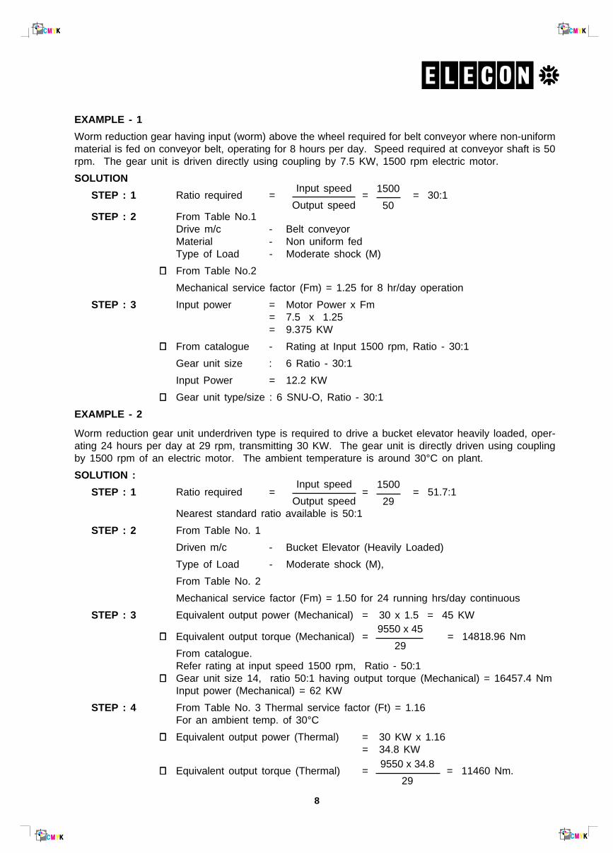
EXAMPLE - 1
Worm reduction gear having input (worm) above the wheel required for belt conveyor where non-uniformmaterial is fed on conveyor belt, operating for 8 hours per day. Speed required at conveyor shaft is 50rpm. The gear unit is driven directly using coupling by 7.5 KW, 1500 rpm electric motor.
SOLUTION
STEP : 1 Ratio required = = = 30:1
STEP : 2 From Table No.1Drive m/c - Belt conveyorMaterial - Non uniform fedType of Load - Moderate shock (M)
∴∴∴∴∴ From Table No.2
Mechanical service factor (Fm) = 1.25 for 8 hr/day operation
STEP : 3 Input power = Motor Power x Fm= 7.5 x 1.25= 9.375 KW
∴∴∴∴∴ From catalogue - Rating at Input 1500 rpm, Ratio - 30:1
Gear unit size : 6 Ratio - 30:1
Input Power = 12.2 KW
∴∴∴∴∴ Gear unit type/size : 6 SNU-O, Ratio - 30:1
EXAMPLE - 2
Worm reduction gear unit underdriven type is required to drive a bucket elevator heavily loaded, oper-ating 24 hours per day at 29 rpm, transmitting 30 KW. The gear unit is directly driven using couplingby 1500 rpm of an electric motor. The ambient temperature is around 30°C on plant.
SOLUTION :
STEP : 1 Ratio required = = = 51.7:1
Nearest standard ratio available is 50:1
STEP : 2 From Table No. 1
Driven m/c - Bucket Elevator (Heavily Loaded)
Type of Load - Moderate shock (M),
From Table No. 2
Mechanical service factor (Fm) = 1.50 for 24 running hrs/day continuous
STEP : 3 Equivalent output power (Mechanical) = 30 x 1.5 = 45 KW
∴∴∴∴∴ Equivalent output torque (Mechanical) = = 14818.96 Nm
From catalogue.Refer rating at input speed 1500 rpm, Ratio - 50:1
∴∴∴∴∴ Gear unit size 14, ratio 50:1 having output torque (Mechanical) = 16457.4 NmInput power (Mechanical) = 62 KW
STEP : 4 From Table No. 3 Thermal service factor (Ft) = 1.16For an ambient temp. of 30°C
∴∴∴∴∴ Equivalent output power (Thermal) = 30 KW x 1.16= 34.8 KW
∴∴∴∴∴ Equivalent output torque (Thermal) = = 11460 Nm.
Input speed
Output speed
1500
50
Input speed
Output speed
1500
29
9550 x 45
29
9550 x 34.8
29
9
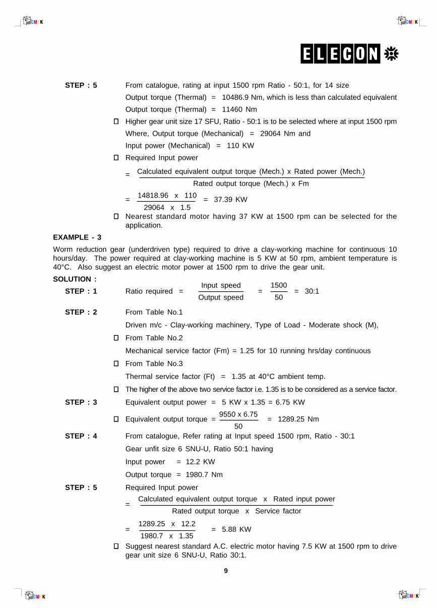
STEP : 5 From catalogue, rating at input 1500 rpm Ratio - 50:1, for 14 size
Output torque (Thermal) = 10486.9 Nm, which is less than calculated equivalent
Output torque (Thermal) = 11460 Nm
∴∴∴∴∴ Higher gear unit size 17 SFU, Ratio - 50:1 is to be selected where at input 1500 rpm
Where, Output torque (Mechanical) = 29064 Nm and
Input power (Mechanical) = 110 KW
∴∴∴∴∴ Required Input power
=
= = 37.39 KW
∴∴∴∴∴ Nearest standard motor having 37 KW at 1500 rpm can be selected for theapplication.
EXAMPLE - 3
Worm reduction gear (underdriven type) required to drive a clay-working machine for continuous 10hours/day. The power required at clay-working machine is 5 KW at 50 rpm, ambient temperature is40°C. Also suggest an electric motor power at 1500 rpm to drive the gear unit.
SOLUTION :
STEP : 1 Ratio required = = = 30:1
STEP : 2 From Table No.1
Driven m/c - Clay-working machinery, Type of Load - Moderate shock (M),
∴∴∴∴∴ From Table No.2
Mechanical service factor (Fm) = 1.25 for 10 running hrs/day continuous
∴∴∴∴∴ From Table No.3
Thermal service factor (Ft) = 1.35 at 40°C ambient temp.
∴∴∴∴∴ The higher of the above two service factor i.e. 1.35 is to be considered as a service factor.
STEP : 3 Equivalent output power = 5 KW x 1.35 = 6.75 KW
∴∴∴∴∴ Equivalent output torque = = 1289.25 Nm
STEP : 4 From catalogue, Refer rating at Input speed 1500 rpm, Ratio - 30:1
Gear unfit size 6 SNU-U, Ratio 50:1 having
Input power = 12.2 KW
Output torque = 1980.7 Nm
STEP : 5 Required Input power
=
= = 5.88 KW
∴∴∴∴∴ Suggest nearest standard A.C. electric motor having 7.5 KW at 1500 rpm to drivegear unit size 6 SNU-U, Ratio 30:1.
Calculated equivalent output torque x Rated input power
Rated output torque x Service factor
1289.25 x 12.2
1980.7 x 1.35
9550 x 6.75
50
Calculated equivalent output torque (Mech.) x Rated power (Mech.)
Rated output torque (Mech.) x Fm
14818.96 x 110
29064 x 1.5
Input speed
Output speed
1500
50

10
GEARRATIO
OUTPUTSPEEDR.P.M.
CAPACITYSIZE OF UNIT
10 12 14 17
INPUT MECH. POWER (KW) 123 196.3 274.3 *
OUTPUT MECH. TORQUE (Nm) 3700.0 5493.6 8224.7 *
INPUT THERMAL POWER (KW) 90 119.4 162 *
OUTPUT THERMAL TORQUE (Nm) 2707.7 3776.85 4857 *
INPUT MECH. POWER (KW) 92 128 184 *
OUTPUT MECH. TORQ;UE (Nm) 4129.4 5699.61 8279.6 *
INPUT THERMAL POWER (KW) 76 108.6 150 *
OUTPUT THERMAL TORQUE (Nm) 3411.3 4806.9 6674.7 *
INPUT MECH. POWER (KW) 65 110.5 162.4 320
OUTPUT MECH. TORQUE (Nm) 3807.3 6557 9635.4 19354.6
INPUT THERMAL POWER (KW) 62 98.7 141 200
OUTPUT THERMAL TORQUE (Nm) 3631.5 6164.6 8358.1 12224
INPUT MECH. POWER (KW) 58 81 150 249
OUTPUT MECH. TORQUE (Nm) 4985.1 7131.87 13349.4 21877
INPUT THERMAL POWER (KW) 56 76 110 177
OUTPUT THERMAL TORQUE (Nm) 4813.2 6670.8 9790.8 15720.5
INPUT MECH. POWER (KW) 55 75 123 216
OUTPUT MECH. TORQUE (Nm) 6303.3 8619 14288.3 25028.6
INPUT THERMAL POWER (KW) 48 63 94.3 160
OUTPUT THERMAL TORQUE (Nm) 5500.8 7239.8 10954.8 18366
INPUT MECH. POWER (KW) 45 67.5 110 172
OUTPUT MECH. TORQUE (Nm) 6303.3 9380.3 14695.4 24365.2
INPUT THERMAL POWER (KW) 39 50 71.6 135
OUTPUT THERMAL TORQUE (Nm) 5462.6 6948.4 9947.3 19124
INPUT MECH. POWER (KW) 40 56 92 158
OUTPUT MECH. TORQUE (Nm) 6494.0 9339.1 14652.2 26556.6
INPUT THERMAL POWER (KW) 32 45 61.2 121
OUTPUT THERMAL TORQUE (Nm) 5195.2 7504.65 9761 20337
INPUT MECH. POWER (KW) 34 51 76 119
OUTPUT MECH. TORQUE (Nm) 7359.9 10830.2 16137.4 26062.6
INPUT THERMAL POWER (KW) 25 37 48 93
OUTPUT THERMAL TORQUE (Nm) 5411.7 7857.8 10192.6 20131.4
INPUT MECH. POWER (KW) 28 44 62 110
OUTPUT MECH. TORQUE (Nm) 7130.7 11404.1 16457.4 29064
INPUT THERMAL POWER (KW) 22 31 39.5 81.6
OUTPUT THERMAL TORQUE (Nm) 5602.7 8740.7 10486.9 21300.32
INPUT MECH. POWER (KW) 24 37 54.8 78
OUTPUT MECH. TORQUE (Nm) 7242.7 11092.2 17520.6 25326.6
INPUT THERMAL POWER (KW) 18 28 33.6 45.2
OUTPUT THERMAL TORQUE (Nm) 5432.0 8397.4 10702.7 17712.6
INPUT MECH. POWER (KW) 21 32 46 75
OUTPUT MECH. TORQUE (Nm) 7309.8 11207 16716.2 27445
INPUT THERMAL POWER (KW) 20 22.5 28.4 57.3
OUTPUT THERMAL TORQUE (Nm) 6961.7 7880.4 10320.1 20456.6
5 300
7.5 200
10 150
15 100
20 75
25 60
30 50
40 37.5
50 30
60 25
70 21.4
RATINGS AT INPUT SPEED 1500 R.P.M.
– The Ratings are based on service factor of 1, continuously transmitted for 12 hours/day with normal overload of 100% momentarily for 15 seconds, 40% for 30 minutes, 25% for 2 hours.– See Page No. 9 for actual service factor to nature of load and duration of operation.– Ratios and output speeds are nominal. Exact ratios are listed on Page No. 30 For rating marked * consult ELECON– Higher rating can be obtained by using SYNTHETIC OIL, details on Page No. 32
11
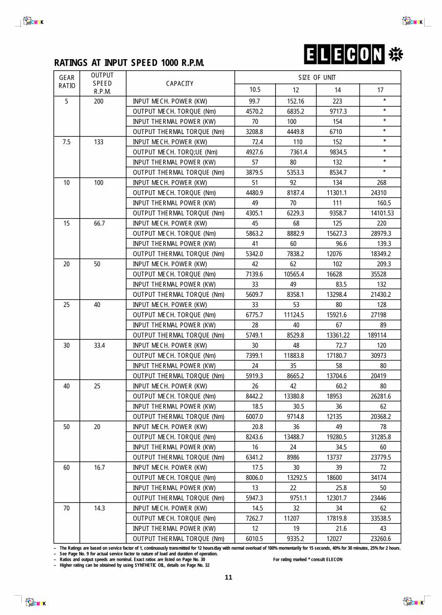
RATINGS AT INPUT SPEED 1000 R.P.M.GEARRATIO
OUTPUTSPEEDR.P.M.
CAPACITYSIZE OF UNIT
10.5 12 14 17
5 200
7.5 133
10 100
15 66.7
20 50
25 40
30 33.4
40 25
50 20
60 16.7
70 14.3
INPUT MECH. POWER (KW) 99.7 152.16 223 *
OUTPUT MECH. TORQUE (Nm) 4570.2 6835.2 9717.3 *
INPUT THERMAL POWER (KW) 70 100 154 *
OUTPUT THERMAL TORQUE (Nm) 3208.8 4449.8 6710 *
INPUT MECH. POWER (KW) 72.4 110 152 *
OUTPUT MECH. TORQ;UE (Nm) 4927.6 7361.4 9834.5 *
INPUT THERMAL POWER (KW) 57 80 132 *
OUTPUT THERMAL TORQUE (Nm) 3879.5 5353.3 8534.7 *
INPUT MECH. POWER (KW) 51 92 134 268
OUTPUT MECH. TORQUE (Nm) 4480.9 8187.4 11301.1 24310
INPUT THERMAL POWER (KW) 49 70 111 160.5
OUTPUT THERMAL TORQUE (Nm) 4305.1 6229.3 9358.7 14101.53
INPUT MECH. POWER (KW) 45 68 125 220
OUTPUT MECH. TORQUE (Nm) 5863.2 8882.9 15627.3 28979.3
INPUT THERMAL POWER (KW) 41 60 96.6 139.3
OUTPUT THERMAL TORQUE (Nm) 5342.0 7838.2 12076 18349.2
INPUT MECH. POWER (KW) 42 62 102 209.3
OUTPUT MECH. TORQUE (Nm) 7139.6 10565.4 16628 35528
INPUT THERMAL POWER (KW) 33 49 83.5 132
OUTPUT THERMAL TORQUE (Nm) 5609.7 8358.1 13298.4 21430.2
INPUT MECH. POWER (KW) 33 53 80 128
OUTPUT MECH. TORQUE (Nm) 6775.7 11124.5 15921.6 27198
INPUT THERMAL POWER (KW) 28 40 67 89
OUTPUT THERMAL TORQUE (Nm) 5749.1 8529.8 13361.22 189114
INPUT MECH. POWER (KW) 30 48 72.7 120
OUTPUT MECH. TORQUE (Nm) 7399.1 11883.8 17180.7 30973
INPUT THERMAL POWER (KW) 24 35 58 80
OUTPUT THERMAL TORQUE (Nm) 5919.3 8665.2 13704.6 20419
INPUT MECH. POWER (KW) 26 42 60.2 80
OUTPUT MECH. TORQUE (Nm) 8442.2 13380.8 18953 26281.6
INPUT THERMAL POWER (KW) 18.5 30.5 36 62
OUTPUT THERMAL TORQUE (Nm) 6007.0 9714.8 12135 20368.2
INPUT MECH. POWER (KW) 20.8 36 49 78
OUTPUT MECH. TORQUE (Nm) 8243.6 13488.7 19280.5 31285.8
INPUT THERMAL POWER (KW) 16 24 34.5 60
OUTPUT THERMAL TORQUE (Nm) 6341.2 8986 13737 23779.5
INPUT MECH. POWER (KW) 17.5 30 39 72
OUTPUT MECH. TORQUE (Nm) 8006.0 13292.5 18600 34174
INPUT THERMAL POWER (KW) 13 22 25.8 50
OUTPUT THERMAL TORQUE (Nm) 5947.3 9751.1 12301.7 23446
INPUT MECH. POWER (KW) 14.5 32 34 62
OUTPUT MECH. TORQUE (Nm) 7262.7 11207 17819.8 33538.5
INPUT THERMAL POWER (KW) 12 19 21.6 43
OUTPUT THERMAL TORQUE (Nm) 6010.5 9335.2 12027 23260.6– The Ratings are based on service factor of 1, continuously transmitted for 12 hours/day with normal overload of 100% momentarily for 15 seconds, 40% for 30 minutes, 25% for 2 hours.– See Page No. 9 for actual service factor to nature of load and duration of operation.– Ratios and output speeds are nominal. Exact ratios are listed on Page No. 30 For rating marked * consult ELECON– Higher rating can be obtained by using SYNTHETIC OIL, details on Page No. 32

12
GEARRATIO
OUTPUTSPEEDR.P.M.
CAPACITYSIZE OF UNIT
10 12 14 17
INPUT MECH. POWER (KW) 105 146.12 200 *
OUTPUT MECH. TORQUE (Nm) 6350.7 8884.3 12173.1 *
INPUT THERMAL POWER (KW) 75 97.5 114 *
OUTPUT THERMAL TORQUE (Nm) 4536.2 5897.1 6822.5 *
INPUT MECH. POWER (KW) 69.5 96.5 140 *
OUTPUT MECH. TORQUE (Nm) 6239.1 8755 12827.2 *
INPUT THERMAL POWER (KW) 50 85.5 130 *
OUTPUT THERMAL TORQUE (Nm) 4488.5 7757 11794.3 *
INPUT MECH. POWER (KW) 53 72.6 105 171.16
OUTPUT MECH. TORQUE (Nm) 6208.8 8689.7 12567.8 20922.6
INPUT THERMAL POWER (KW) 45 65.3 86.75 137.5
OUTPUT THERMAL TORQUE (Nm) 5271.6 7816 10272.9 16808
INPUT MECH. POWER (KW) 45 59 85 137.5
OUTPUT MECH. TORQUE (Nm) 7735.5 10360.5 15260.9 25212
INPUT THERMAL POWER (KW) 34 53.13 73 123.2
OUTPUT THERMAL TORQUE (Nm) 5844.6 9336 13106.4 22590
INPUT MECH. POWER (KW) 38 46.86 62 101.65
OUTPUT MECH. TORQUE (Nm) 8612.8 10979 14526.2 24074.8
INPUT THERMAL POWER (KW) 27 42.88 58 88
OUTPUT THERMAL TORQUE (Nm) 6119.6 10046.5 13441.3 20841.9
INPUT MECH. POWER (KW) 30 36 57 86.35
OUTPUT MECH. TORQUE (Nm) 8308.5 10279.6 16512 25563.9
INPUT THERMAL POWER (KW) 24 32 52 65
OUTPUT THERMAL TORQUE (Nm) 6646.8 9168 15063.5 19243.3
INPUT MECH. POWER (KW) 23 33.73 45.11 72
OUTPUT MECH. TORQUE (Nm) 7204.5 11341 15508.8 14027
INPUT THERMAL POWER (KW) 21 31.25 41.25 68
OUTPUT THERMAL TORQUE (Nm) 6578.0 10505 14181.8 23378.4
INPUT MECH. POWER (KW) 20 26.5 41.8 68.53
OUTPUT MECH. TORQUE (Nm) 8330.9 10996.7 18897.8 30634.4
INPUT THERMAL POWER (KW) 16 24 33 58
OUTPUT THERMAL TORQUE (Nm) 6664.7 9997 14919.3 25927.2
INPUT MECH. POWER (KW) 18 23.2 32 52.05
OUTPUT MECH. TORQUE (Nm) 8938.8 11225.7 17724.8 28167.7
INPUT THERMAL POWER (KW) 15 21.45 22 48.75
OUTPUT THERMAL TORQUE (Nm) 7449.0 10105.9 12185.8 26381.9
INPUT MECH. POWER (KW) 14 18.8 24.2 40.6
OUTPUT MECH. TORQUE (Nm) 8347.3 10778.1 16085.3 26055.5
INPUT THERMAL POWER (KW) 11 17 23 36
OUTPUT THERMAL TORQUE (Nm) 6558.6 9741 15287.6 23103.4
INPUT MECH. POWER (KW) 10 16.5 20.8 34.1
OUTPUT MECH. TORQUE (Nm) 6693.9 11045 14851.6 24956.7
INPUT THERMAL POWER (KW) 8 14.8 19.5 32
OUTPUT THERMAL TORQUE (Nm) 5355.1 9774.9 13923.4 23419
5 150
7.5 100
10 75
15 50
20 37.5
25 30
30 25
40 18.8
50 15
60 12.5
70 10.7
RATINGS AT INPUT SPEED 750 R.P.M.
– The Ratings are based on service factor of 1, continuously transmitted for 12 hours/day with normal overload of 100% momentarily for 15 seconds, 40% for 30 minutes, 25% for 2 hours.– See Page No. 9 for actual service factor to nature of load and duration of operation.– Ratios and output speeds are nominal. Exact ratios are listed on Page No. 30 For rating marked * consult ELECON– Higher rating can be obtained by using SYNTHETIC OIL, details on Page No. 32

13
GEARRATIO
OUTPUTSPEEDR.P.M.
CAPACITYSIZE OF UNIT
10 12 14 17
INPUT MECH. POWER (KW) 75 102.5 122 *
OUTPUT MECH. TORQUE (Nm) 6732.8 9299.3 11068.5 *
INPUT THERMAL POWER (KW) 40 49.2 57.5 *
OUTPUT THERMAL TORQUE (Nm) 3590.8 4463.7 5213.1 *
INPUT MECH. POWER (KW) 47 56.6 95 *
OUTPUT MECH. TORQUE (Nm) 6312.1 7617.7 12785.8 *
INPUT THERMAL POWER (KW) 35 45.48 50.2 *
OUTPUT THERMAL TORQUE (Nm) 4700.5 6121.1 6756.3 *
INPUT MECH. POWER (KW) 40 51.72 70.65 130.8
OUTPUT MECH. TORQUE (Nm) 7138.3 9187.1 12549.6 23558.8
INPUT THERMAL POWER (KW) 29 40 49.25 96.72
OUTPUT THERMAL TORQUE (Nm) 5175.3 7105.2 8748.3 17420.5
INPUT MECH. POWER (KW) 30 42.56 58.8 102.36
OUTPUT MECH. TORQUE (Nm) 7880.9 10985.1 15345.4 27300.6
INPUT THERMAL POWER (KW) 24 33.45 37.31 80.6
OUTPUT THERMAL TORQUE (Nm) 6304.7 8633.7 9737 21497
INPUT MECH. POWER (KW) 22 35.2 45.6 91.5
OUTPUT MECH. TORQUE (Nm) 7395.6 11873.2 15677.3 31807.2
INPUT THERMAL POWER (KW) 20 29.8 34.3 72.76
OUTPUT THERMAL TORQUE (Nm) 6723.2 10051.7 11792.3 25292.8
INPUT MECH. POWER (KW) 18 29 41.2 82
OUTPUT MECH. TORQUE (Nm) 7219.8 11922.7 17312.2 34652.2
INPUT THERMAL POWER (KW) 15 24.17 30.55 64.5
OUTPUT THERMAL TORQUE (Nm) 6016.5 9937 12837.1 27257
INPUT MECH. POWER (KW) 16 25.6 33.83 64.37
OUTPUT MECH. TORQUE (Nm) 7547.9 12371.3 16737.7 32218
INPUT THERMAL POWER (KW) 14 19 26.6 56.42
OUTPUT THERMAL TORQUE (Nm) 6604.4 9181.8 13160.6 28239
INPUT MECH. POWER (KW) 15 23.3 31.5 66.7
OUTPUT MECH. TORQUE (Nm) 8938.8 13884.9 19252.8 42805.4
INPUT THERMAL POWER (KW) 12 17.2 20.52 47.35
OUTPUT THERMAL TORQUE (Nm) 7151.0 10249.8 12541.8 30387.3
INPUT MECH. POWER (KW) 14 18.6 26.6 48
OUTPUT MECH. TORQUE (Nm) 10027.5 13322.3 20068.4 36672
INPUT THERMAL POWER (KW) 10 14.16 17.35 37.27
OUTPUT THERMAL TORQUE (Nm) 7162.5 10142.1 13086.7 28474.3
INPUT MECH. POWER (KW) 10 15.7 20.7 38
OUTPUT MECH. TORQUE (Nm) 8254.5 13139.6 18036.1 33981
INPUT THERMAL POWER (KW) 8.5 12.5 15.6 33.25
OUTPUT THERMAL TORQUE (Nm) 7016.3 10461.4 13532.4 29733.4
INPUT MECH. POWER (KW) 8.8 14.36 16.12 30
OUTPUT MECH. TORQUE (Nm) 8592.3 13962.5 16170.8 30495.8
INPUT THERMAL POWER (KW) 6.9 11.5 14.2 28.7
OUTPUT THERMAL TORQUE (Nm) 6737.2 11228.6 14244.8 29174.3
5 100
7.5 66.7
10 50
15 33.3
20 25
25 20
30 16.6
40 12.5
50 10
60 8.33
70 7.14
RATINGS AT INPUT SPEED 500 R.P.M.
–– The Ratings are based on service factor of 1, continuously transmitted for 12 hours/day with normal overload of 100% momentarily for 15 seconds, 40% for 30 minutes, 25% for 2 hours.– See Page No. 9 for actual service factor to nature of load and duration of operation.– Ratios and output speeds are nominal. Exact ratios are listed on Page No. 30 For rating marked * consult ELECON– Higher rating can be obtained by using SYNTHETIC OIL, details on Page No. 32
14
k3k2L1
V1d
1D
1
C
bm
f
s
t2t1
u1
u1
k1
OUTPUT SHAFTKEYWAY DETAIL
INPUT SHAFTKEYWAY DETAIL
FILLER PLUG
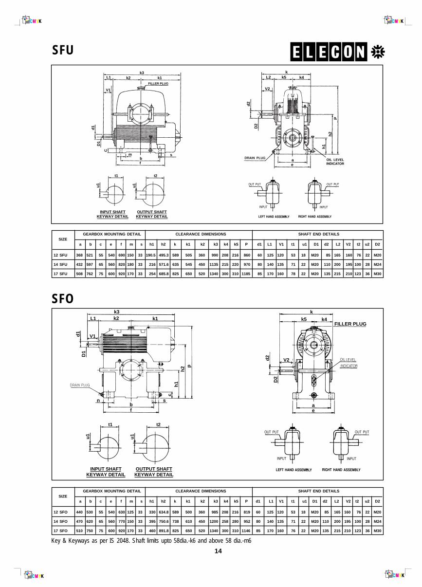
SFU
SFO
SIZEGEARBOX MOUNTING DETAIL CLEARANCE DIMENSIONS SHAFT END DETAILS
a b c e f m s h1 h2 k k1 k2 k3 k4 k5 P d1 L1 V1 t1 u1 D1 d2 L2 V2 t2 u2 D2
12 SFU 368 521 55 540 690 150 33 190.5 495.3 589 505 360 990 208 216 860 60 125 120 53 18 M20 85 165 160 76 22 M20
14 SFU 432 597 65 560 820 180 33 216 571.6 635 545 450 1135 215 220 970 80 140 135 71 22 M20 110 200 195 100 28 M24
17 SFU 508 762 75 600 920 170 33 254 685.8 825 650 520 1340 300 310 1185 85 170 160 78 22 M20 135 215 210 123 36 M30
Key & Keyways as per IS 2048. Shaft limits upto 58dia.-k6 and above 58 dia.-m6
SIZEGEARBOX MOUNTING DETAIL CLEARANCE DIMENSIONS SHAFT END DETAILS
a b c e f m s h1 h2 k k1 k2 k3 k4 k5 P d1 L1 V1 t1 u1 D1 d2 L2 V2 t2 u2 D2
12 SFO 440 530 55 540 630 125 33 330 634.8 589 500 360 985 208 216 819 60 125 120 53 18 M20 85 165 160 76 22 M20
14 SFO 470 620 65 560 770 150 33 395 750.6 738 610 450 1200 258 280 952 80 140 135 71 22 M20 110 200 195 100 28 M24
17 SFO 510 750 75 600 920 170 33 460 891.8 825 650 520 1340 300 310 1146 85 170 160 76 22 M20 135 215 210 123 36 M30
kk5
ae
k4L2
V2
d2
D2
Ph
2
h1
k3k2
d1
D1
k1k
FILLER PLUGk5 k4
V2
ae
d2
D2
p
c
snbf
h2
h1
L1
V1
t2t1
u1
u1
OUTPUT SHAFTKEYWAY DETAIL
INPUT SHAFTKEYWAY DETAIL
15
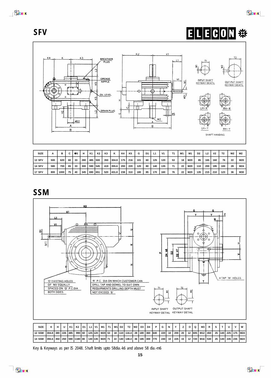
SFV
SSM
12 SFV 500 620 60 33 280 485 500 350 304.8 175 216 101 60 125 120 53 18 M20 85 165 160 76 22 M20
14 SFV 580 700 65 33 300 590 545 419 355.6 200 220 120 80 140 135 71 22 M20 110 200 195 100 28 M24
17 SFV 800 1000 75 40 345 690 651 520 431.8 238 310 180 85 170 160 76 22 M20 135 215 210 123 36 M30
SIZE K H U K1 K2 D1 L1 V1 M1 T1 W1 D2 T2 W2 D3 D4 P G N Y Z O Q M3 R S T U V W
12 SSM 304.8 380 226 485 990 60 125 120 M20 53 18 110 116.4 28 180 360 640 220 10 200 20 12 605 M12 450 25 140 225 175 M24
14 SSM 355.6 450 250 590 1180 80 140 135 M20 71 22 140 148.4 36 185 400 770 240 10 225 15 12 720 M16 530 25 140 226 235 M24
Key & Keyways as per IS 2048. Shaft limits upto 58dia.-k6 and above 58 dia.-m6
SIZE A B C ΦΦΦΦΦS H K1 K2 K3 K K4 K5 G D1 L1 V1 T1 W1 M1 D2 L2 V2 T2 W2 M2
16
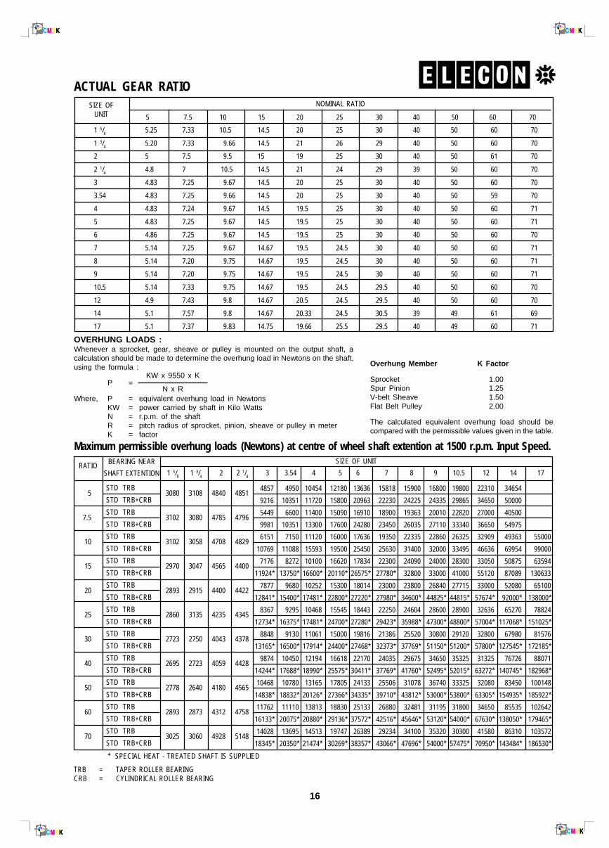
ACTUAL GEAR RATIO
1 5/8 5.25 7.33 10.5 14.5 20 25 30 40 50 60 70
1 3/4 5.20 7.33 9.66 14.5 21 26 29 40 50 60 70
2 5 7.5 9.5 15 19 25 30 40 50 61 70
2 1/4 4.8 7 10.5 14.5 21 24 29 39 50 60 70
3 4.83 7.25 9.67 14.5 20 25 30 40 50 60 70
3.54 4.83 7.25 9.66 14.5 20 25 30 40 50 59 70
4 4.83 7.24 9.67 14.5 19.5 25 30 40 50 60 71
5 4.83 7.25 9.67 14.5 19.5 25 30 40 50 60 71
6 4.86 7.25 9.67 14.5 19.5 25 30 40 50 60 70
7 5.14 7.25 9.67 14.67 19.5 24.5 30 40 50 60 71
8 5.14 7.20 9.75 14.67 19.5 24.5 30 40 50 60 71
9 5.14 7.20 9.75 14.67 19.5 24.5 30 40 50 60 71
10.5 5.14 7.33 9.75 14.67 19.5 24.5 29.5 40 50 60 70
12 4.9 7.43 9.8 14.67 20.5 24.5 29.5 40 50 60 70
14 5.1 7.57 9.8 14.67 20.33 24.5 30.5 39 49 61 69
17 5.1 7.37 9.83 14.75 19.66 25.5 29.5 40 49 60 71
NOMINAL RATIO
5 7.5 10 15 20 25 30 40 50 60 70
SIZE OFUNIT
Overhung Member K Factor
Sprocket 1.00Spur Pinion 1.25V-belt Sheave 1.50Flat Belt Pulley 2.00
The calculated equivalent overhung load should becompared with the permissible values given in the table.
OVERHUNG LOADS :Whenever a sprocket, gear, sheave or pulley is mounted on the output shaft, acalculation should be made to determine the overhung load in Newtons on the shaft,using the formula :
P =
Where, P = equivalent overhung load in NewtonsKW = power carried by shaft in Kilo WattsN = r.p.m. of the shaftR = pitch radius of sprocket, pinion, sheave or pulley in meterK = factor
KW x 9550 x K
N x R
Maximum permissible overhung loads (Newtons) at centre of wheel shaft extention at 1500 r.p.m. Input Speed.
4857 4950 10454 12180 13636 15818 15900 16800 19800 22310 34654
9216 10351 11720 15800 20963 22230 24225 24335 29865 34650 50000
5449 6600 11400 15090 16910 18900 19363 20010 22820 27000 40500
9981 10351 13300 17600 24280 23450 26035 27110 33340 36650 54975
6151 7150 11120 16000 17636 19350 22335 22860 26325 32909 49363 55000
10769 11088 15593 19500 25450 25630 31400 32000 33495 46636 69954 99000
7176 8272 10100 16620 17834 22300 24090 24000 28300 33050 50875 63594
11924* 13750* 16600* 20110* 26575* 27780* 32800 33000 41000 55120 87089 130633
7877 9680 10252 15300 18014 23000 23800 26840 27715 33000 52080 65100
12841* 15400* 17481* 22800* 27220* 27980* 34600* 44825* 44815* 57674* 92000* 138000*
8367 9295 10468 15545 18443 22250 24604 28600 28900 32636 65270 78824
12734* 16375* 17481* 24700* 27280* 29423* 35988* 47300* 48800* 57004* 117068* 151025*
8848 9130 11061 15000 19816 21386 25520 30800 29120 32800 67980 81576
13165* 16500* 17914* 24400* 27468* 32373* 37769* 51150* 51200* 57800* 127545* 172185*
9874 10450 12194 16618 22170 24035 29675 34650 35325 31325 76726 88071
14244* 17688* 18990* 25575* 30411* 37769* 41760* 52495* 52015* 63272* 140745* 182968*
10468 10780 13165 17805 24133 25506 31078 36740 33325 32080 83450 100148
14838* 18832* 20126* 27366* 34335* 39710* 43812* 53000* 53800* 63305* 154935* 185922*
11762 11110 13813 18830 25133 26880 32481 31195 31800 34650 85535 102642
16133* 20075* 20880* 29136* 37572* 42516* 45646* 53120* 54000* 67630* 138050* 179465*
14028 13695 14513 19747 26389 29234 34100 35320 30300 41580 86310 103572
18345* 20350* 21474* 30269* 38357* 43066* 47696* 54000* 57475* 70950* 143484* 186530*
3080 3108 4840 4851
3102 3080 4785 4796
3102 3058 4708 4829
2970 3047 4565 4400
2893 2915 4400 4422
2860 3135 4235 4345
2723 2750 4043 4378
2695 2723 4059 4428
2778 2640 4180 4565
2893 2873 4312 4758
3025 3060 4928 5148
* SPECIAL HEAT - TREATED SHAFT IS SUPPLIED
TRB = TAPER ROLLER BEARINGCRB = CYLINDRICAL ROLLER BEARING
5
7.5
10
15
20
25
30
40
50
60
70
RATIO BEARING NEAR
SHAFT EXTENTION
STD TRB
STD TRB+CRB
STD TRB
STD TRB+CRB
STD TRB
STD TRB+CRB
STD TRB
STD TRB+CRB
STD TRB
STD TRB+CRB
STD TRB
STD TRB+CRB
STD TRB
STD TRB+CRB
STD TRB
STD TRB+CRB
STD TRB
STD TRB+CRB
STD TRB
STD TRB+CRB
STD TRB
STD TRB+CRB
SIZE OF UNIT
1 5/8 1 3/4 2 2 1/4 3 3.54 4 5 6 7 8 9 10.5 12 14 17
17
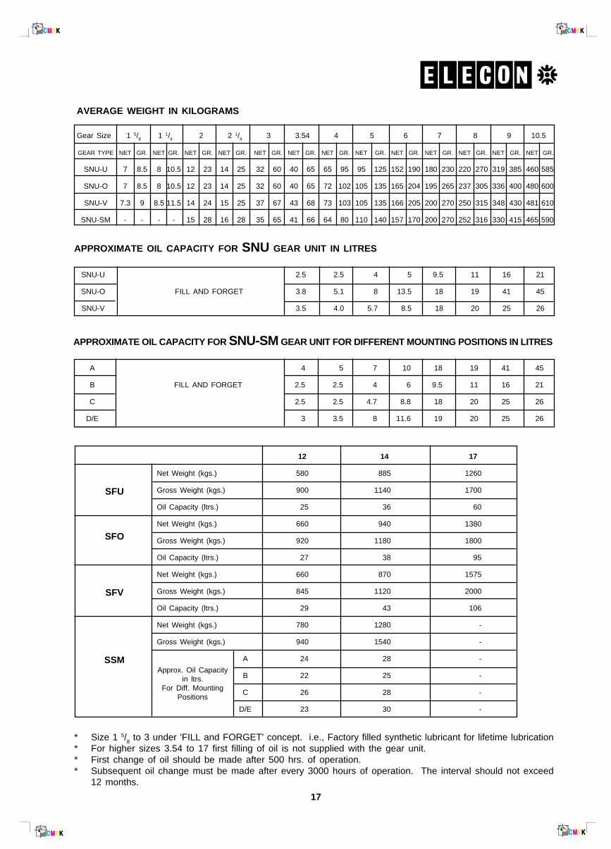
AVERAGE WEIGHT IN KILOGRAMS
Gear Size 1 5/8 1 1/4 2 2 1/4 3 3.54 4 5 6 7 8 9 10.5
GEAR TYPE NET GR. NET GR. NET GR. NET GR. NET GR. NET GR. NET GR. NET GR. NET GR. NET GR. NET GR. NET GR. NET GR.
SNU-U 7 8.5 8 10.5 12 23 14 25 32 60 40 65 65 95 95 125 152 190 180 230 220 270 319 385 460 585
SNU-O 7 8.5 8 10.5 12 23 14 25 32 60 40 65 72 102 105 135 165 204 195 265 237 305 336 400 480 600
SNU-V 7.3 9 8.5 11.5 14 24 15 25 37 67 43 68 73 103 105 135 166 205 200 270 250 315 348 430 481 610
SNU-SM - - - - 15 28 16 28 35 65 41 66 64 80 110 140 157 170 200 270 252 316 330 415 465 590
12 14 17
Net Weight (kgs.) 580 885 1260
Gross Weight (kgs.) 900 1140 1700
Oil Capacity (ltrs.) 25 36 60
Net Weight (kgs.) 660 940 1380
Gross Weight (kgs.) 920 1180 1800
Oil Capacity (ltrs.) 27 38 95
Net Weight (kgs.) 660 870 1575
Gross Weight (kgs.) 845 1120 2000
Oil Capacity (ltrs.) 29 43 106
Net Weight (kgs.) 780 1280 -
Gross Weight (kgs.) 940 1540 -
A 24 28 -
B 22 25 -
C 26 28 -
D/E 23 30 -
SFU
SFO
SFV
SSM
* Size 1 5/8 to 3 under 'FILL and FORGET' concept. i.e., Factory filled synthetic lubricant for lifetime lubrication
* For higher sizes 3.54 to 17 first filling of oil is not supplied with the gear unit.* First change of oil should be made after 500 hrs. of operation.* Subsequent oil change must be made after every 3000 hours of operation. The interval should not exceed
12 months.
APPROXIMATE OIL CAPACITY FOR SNU GEAR UNIT IN LITRES
SNU-U 2.5 2.5 4 5 9.5 11 16 21
SNU-O FILL AND FORGET 3.8 5.1 8 13.5 18 19 41 45
SNU-V 3.5 4.0 5.7 8.5 18 20 25 26
APPROXIMATE OIL CAPACITY FOR SNU-SM GEAR UNIT FOR DIFFERENT MOUNTING POSITIONS IN LITRES
A 4 5 7 10 18 19 41 45
B FILL AND FORGET 2.5 2.5 4 6 9.5 11 16 21
C 2.5 2.5 4.7 8.8 18 20 25 26
D/E 3 3.5 8 11.6 19 20 25 26
Approx. Oil Capacityin ltrs.
For Diff. MountingPositions
18
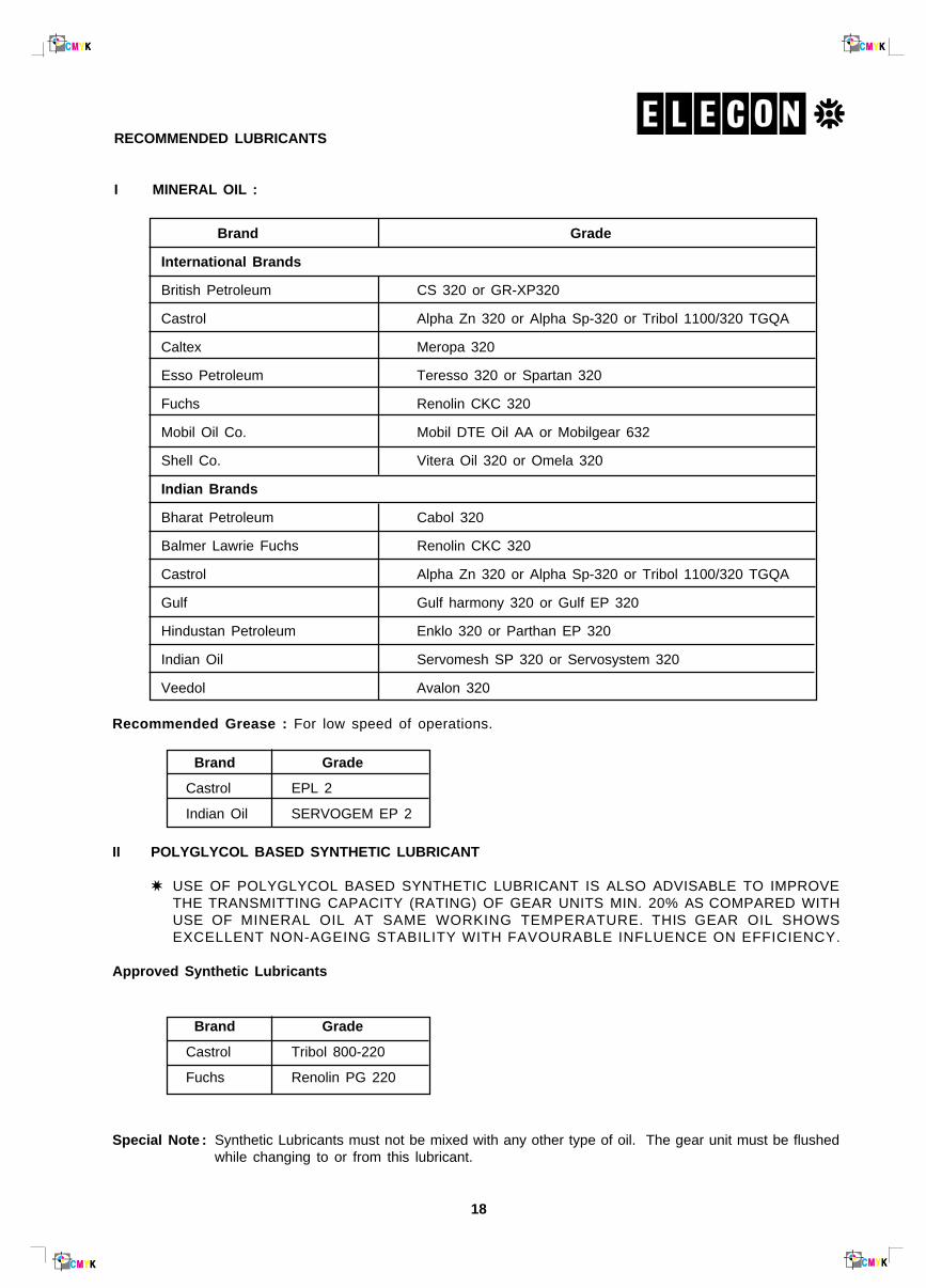
RECOMMENDED LUBRICANTS
I MINERAL OIL :
Brand Grade
International Brands
British Petroleum CS 320 or GR-XP320
Castrol Alpha Zn 320 or Alpha Sp-320 or Tribol 1100/320 TGQA
Caltex Meropa 320
Esso Petroleum Teresso 320 or Spartan 320
Fuchs Renolin CKC 320
Mobil Oil Co. Mobil DTE Oil AA or Mobilgear 632
Shell Co. Vitera Oil 320 or Omela 320
Indian Brands
Bharat Petroleum Cabol 320
Balmer Lawrie Fuchs Renolin CKC 320
Castrol Alpha Zn 320 or Alpha Sp-320 or Tribol 1100/320 TGQA
Gulf Gulf harmony 320 or Gulf EP 320
Hindustan Petroleum Enklo 320 or Parthan EP 320
Indian Oil Servomesh SP 320 or Servosystem 320
Veedol Avalon 320
II POLYGLYCOL BASED SYNTHETIC LUBRICANT
✷ USE OF POLYGLYCOL BASED SYNTHETIC LUBRICANT IS ALSO ADVISABLE TO IMPROVETHE TRANSMITTING CAPACITY (RATING) OF GEAR UNITS MIN. 20% AS COMPARED WITHUSE OF MINERAL OIL AT SAME WORKING TEMPERATURE. THIS GEAR OIL SHOWSEXCELLENT NON-AGEING STABILITY WITH FAVOURABLE INFLUENCE ON EFFICIENCY.
Approved Synthetic Lubricants
Brand Grade
Castrol Tribol 800-220
Fuchs Renolin PG 220
Special Note : Synthetic Lubricants must not be mixed with any other type of oil. The gear unit must be flushedwhile changing to or from this lubricant.
Recommended Grease : For low speed of operations.
Brand Grade
Castrol EPL 2
Indian Oil SERVOGEM EP 2
19
L
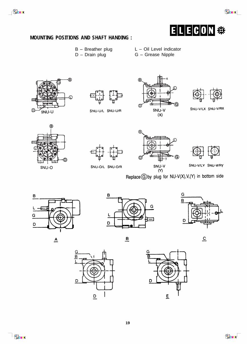
MOUNTING POSITIONS AND SHAFT HANDING :
B – Breather plugD – Drain plug
L – Oil Level indicatorG – Grease Nipple
20
OPTIONAL STANDARD FEATURES
1. SPRAG Holdbacks for Non-reversible DrivesELECON gear unit can be supplied, fitted with sprag holdback for non-reversible drives it is essential thatthe load or driven mechanism is prevented from running backwards after the driving motor is stripped e.g.inclined conveyors, elevator, winches etc.
The sprag holdback is incorporated on the fan end side of the high speed shaft. Visually and dimensionallythe ELECON unit is unchanged. The hold back can be provided for either direction of rotation and the sameshould be specified when ordering.
2. Base FrameFabricated steel base frames are also supplied when requires.
3. Steel Gearcases
ELECON gear unit can be supplied with cast or fabricated steel cases for heavy duty application whenloadings on the housings are in excess of the capacities of standard cast iron cases.
4. Wormwheel constructionStandard worm wheel comprise phosphourous bronze rims continuous welded to cast iron centres, wherethe duties demand rims are welded to steel centres.
5. Slow speed shafts
ELECON gear unit can be supplied with special slow speed shafts where required, These include units withspecial single extension, double extended shafts to the standard dimensions listed in this catalogue orspecial double ended extension. Additionally single or double ended shaft can be supplied in high tensilesteel to heavy duty applications.
21
PRODUCT SAFETY INFORMATION
General ELECON gear units will operate safety provided that they are selected, installed, usedand maintained property. As with any equipment consists of rotating swhafts andtransmitting power, adequate guarding is necessary to elimiate the possibility of physi-cal contact with rotating shafts or coupling.
Potential Hazards The following points should be noted and brought to attention to the persons involved
in the installation, use and maintenance of equipment.
1. For lifting of gearunit eye-bolts or lifting points (on larger units) should be used.
2. Check the grade and quantity of lubrication before commissioning. Read and carry out all instructions onlubricant plate and in the installation and maintenance manual literature.
3. Installation must be performed in accordance with the manufacturer's instruction and be undertaken bysuitably qualified personnel.
4. Ensure the proper maintenance of gearboxes in operation. USE ONLY ELECON SPARES FOR GEAR-BOXES.
5. The oil level should be examined periodically, if required the oil should be filled again.
6. The operating speeds, transmitting powers, generated torques or the external loads must not exceed thedesign values.
7. The driving and the driven equipment must be correctly selected to ensure that the complete installation ofthe machinery will perform satisfactorily e.g. avoiding system critical speeds, system torsional vibration etc.
As improvement in designing are continuously being made, the details and dimensions are subject to alterationwithout notice.
Any other required information or clarification can be obtained by writing to :
ELECON ENGINEERING CO. LTD.POST BOX # 6, VALLABH VIDYANAGAR 388 120, GUJARAT, INDIA