Embed Size (px)
Citation preview


�������

International Civil Aviation Organization
Approved by the Secretary Generaland published under his authority
World GeodeticSystem — 1984(WGS-84) Manual
Second Edition — 2002
Doc 9674AN/946

AMENDMENTS
The issue of amendments is announced regularly in the ICAO Journal and in themonthly Supplement to the Catalogue of ICAO Publications and Audio-visualTraining Aids, which holders of this publication should consult. The space belowis provided to keep a record of such amendments.
RECORD OF AMENDMENTS AND CORRIGENDA
AMENDMENTS CORRIGENDA
No. Date Entered by No. Date Entered by
(ii)

(iii)
FOREWORD
The Council of the International Civil Aviation Organiza-tion (ICAO), at the thirteenth meeting of its 126th Sessionon 3 March 1989, approved Recommendation 3.2/1 of thefourth meeting of the Special Committee on Future AirNavigation Systems (FANS/4) concerning the adoption ofthe World Geodetic System — 1984 (WGS-84) as thestandard geodetic reference system for future navigationwith respect to international civil aviation. FANS/4Recommendation 3.2/1 reads:
“Recommendation.— Adoption of WGS-84
That ICAO adopts, as a standard, the geodetic referencesystem WGS-84 and develops appropriate ICAOmaterial, particularly in respect of Annexes 4 and 15, inorder to ensure a rapid and comprehensive implemen-tation of the WGS-84 geodetic reference system.”
The Council, at the ninth meeting of its 141st Session on28 February 1994, adopted Amendment 28 to Annex 15,introducing the provisions concerning the promulgation ofWGS-84-related geographical coordinates. Consequentialamendments to Annexes 4, 11 and 14, Volumes I and II,were adopted by the Council on 1 March 1995,18 March 1994 and 13 March 1995, respectively. On20 March 1997 the Council, at the seventeenth meeting ofits 150th Session, adopted Amendment 29 to Annex 15introducing publication of the vertical component of theWGS-84 geodetic reference system. Consequential amend-ments to Annexes 4 and 14, Volumes I and II, were adoptedby the Council on 20 March 1998 and 21 March 1997,respectively. The Standards and Recommended Practices(SARPs) in Annexes 11 and 14, Volumes I and II, governthe determination (accuracy of the field work) andreporting of geographic coordinates in terms of the WGS-84 geodetic reference system. Annexes 4 and 15 SARPsgovern the publication in textual or graphical form ofgeographic coordinates (resolution) and vertical
components. States’ aeronautical information servicedepartments will publish in their Aeronautical InformationPublications (AIPs), on charts and store in electronicdatabases where applicable, geographic coordinate andvertical component values based on WGS-84 which aresupplied by the other State aeronautical services, such asthe air traffic service and the aerodrome/heliport authority.
The purpose of this manual is to furnish guidance on theprovision of geographic coordinates and verticalcomponent values referenced to the WGS-84 datum inorder to assist States in the uniform implementation of theSARPs on WGS-84 as contained in:
Annex 4 — Aeronautical Charts;
Annex 11 — Air Traffic Services;
Annex 14 — Aerodromes,Volume I — Aerodrome Design and Operations andVolume II — Heliports;
Annex 15 — Aeronautical Information Services.
This manual has been prepared in consultation andcoordination with the European Organization for the Safetyof Air Navigation (EUROCONTROL) and will beamended periodically. Users are invited to forward to ICAOsuggestions for improvements or additions based on theirpractical experience when using the manual. Errors ordiscrepancies noticed in the manual should be brought tothe attention of:
The Secretary GeneralInternational Civil Aviation Organization999 University StreetMontreal, Quebec, Canada H3C 5H7

�������

(v)
TABLE OF CONTENTS
Page Page
Chapter 1. Introduction . . . . . . . . . . . . . . . . . . . . 1-1
1.1 Effects of using differingcoordinate reference systemsin aviation . . . . . . . . . . . . . . . . . . . . . . . . . . 1-1
1.2 Magnitude of the problem. . . . . . . . . . . . . . 1-21.3 Navigational implications . . . . . . . . . . . . . . 1-21.4 Solution to the problem. . . . . . . . . . . . . . . . 1-2Figures for Chapter 1 . . . . . . . . . . . . . . . . . . . . . . 1-4
Chapter 2. Accuracy, Resolution andIntegrity of Aeronautical Data . . . . . . . . . . . . . . . . 2-1
2.1 General. . . . . . . . . . . . . . . . . . . . . . . . . . . . . 2-12.2 Type and classification of positional
data. . . . . . . . . . . . . . . . . . . . . . . . . . . . . . . . 2-12.3 Source of raw aeronautical data . . . . . . . . . 2-12.4 Accuracy requirements . . . . . . . . . . . . . . . . 2-22.5 Resolution requirements . . . . . . . . . . . . . . . 2-32.6 Integrity requirements . . . . . . . . . . . . . . . . . 2-3Tables for Chapter 2 . . . . . . . . . . . . . . . . . . . . . . . 2-4
Chapter 3. The Global WGS-84 CoordinateSystem . . . . . . . . . . . . . . . . . . . . . . . . . . . . . . . . . . . . 3-1
3.1 Definition of the WGS-84 coordinatesystem . . . . . . . . . . . . . . . . . . . . . . . . . . . . . 3-1
3.2 Realization of the WGS-84 coordinatesystem . . . . . . . . . . . . . . . . . . . . . . . . . . . . . 3-1
3.3 Accuracy of WGS-84 coordinates . . . . . . . 3-1Figures for Chapter 3 . . . . . . . . . . . . . . . . . . . . . . 3-3
Chapter 4. A guide to obtain WGS-84coordinates . . . . . . . . . . . . . . . . . . . . . . . . . . . . . . . . . 4-1
4.1 General. . . . . . . . . . . . . . . . . . . . . . . . . . . . . 4-14.2 Scenario 1: Coordinates in a local
reference frame are available . . . . . . . . . . . 4-14.3 Scenario 2: Coordinates of the required
accuracy are not available . . . . . . . . . . . . . . 4-34.4 Scenario 3: Digitized coordinates from
maps are available . . . . . . . . . . . . . . . . . . . . 4-4Figures for Chapter 4 . . . . . . . . . . . . . . . . . . . . . . 4-6
Chapter 5. Surveying guidance . . . . . . . . . . . . . . 5-1
5.1 Introduction . . . . . . . . . . . . . . . . . . . . . . . . . 5-15.2 General specifications . . . . . . . . . . . . . . . . . 5-15.3 Survey requirements for aerodrome/
heliport-related navigation elements . . . . . . 5-45.4 Aerodrome/heliport survey report
requirements . . . . . . . . . . . . . . . . . . . . . . . . 5-55.5 Survey requirements for navigation aids . . 5-65.6 En-route survey report requirements . . . . . 5-75.7 Use of software . . . . . . . . . . . . . . . . . . . . . . 5-75.8 Digital format for the delivery of
survey data. . . . . . . . . . . . . . . . . . . . . . . . . . 5-7
Attachment A to Chapter 5. Monumentation . . . . . 5-8
1. General . . . . . . . . . . . . . . . . . . . . . . . . . . . . . . . 5-82. Numbering system for survey markers . . . . . . 5-8Figures for Attachment A . . . . . . . . . . . . . . . . . . . 5-9
Attachment B to Chapter 5. Description ofgeographical positions . . . . . . . . . . . . . . . . . . . . . . 5-12Figures for Attachment B . . . . . . . . . . . . . . . . . . . 5-13
Attachment C to Chapter 5. Survey reports . . . . . . 5-32
1. Geodetic connection . . . . . . . . . . . . . . . . . . . . . 5-322. Aerodrome/heliport survey. . . . . . . . . . . . . . . . 5-323. En-route survey . . . . . . . . . . . . . . . . . . . . . . . . 5-32
Attachment D to Chapter 5. Computation ofthreshold coordinates . . . . . . . . . . . . . . . . . . . . . . . 5-34
Chapter 6. Quality assurance. . . . . . . . . . . . . . . . 6-1
6.1 Quality definitions. . . . . . . . . . . . . . . . . . . . 6-16.2 Quality assurance (QA). . . . . . . . . . . . . . . . 6-2Figures for Chapter 6 . . . . . . . . . . . . . . . . . . . . . . 6-5
Chapter 7. Deliverables. . . . . . . . . . . . . . . . . . . . . 7-1
7.1 Survey reporting requirements . . . . . . . . . . 7-17.2 Basic reporting structure . . . . . . . . . . . . . . . 7-1

(vi) World Geodetic System — 1984 (WGS-84) Manual
Page Page
7.3 Formats, standard algorithms andworking practices. . . . . . . . . . . . . . . . . . . . . 7-2
Figures for Chapter 7 . . . . . . . . . . . . . . . . . . . . . . 7-6
Appendix A. The Global PositioningSystem (GPS). . . . . . . . . . . . . . . . . . . . . . . . . . . . . . . A-1
Figures for Appendix A . . . . . . . . . . . . . . . . . . . . A-6
Appendix B. Principles of geodesy. . . . . . . . . . . . B-1Figures for Appendix B. . . . . . . . . . . . . . . . . . . . . B-7
Appendix C. The International TerrestrialReference System (ITRS). . . . . . . . . . . . . . . . . . . . . C-1
Appendix D. Datum transformation formulae . . . . . . . . . . . . . . . . . . . . . . . . . . . . . . . . . . . D-1
Figure for Appendix D . . . . . . . . . . . . . . . . . . . . . D-5
Appendix E. Surveying and photogrammetricmethods . . . . . . . . . . . . . . . . . . . . . . . . . . . . . . . . . . . E-1
Figures for Appendix E. . . . . . . . . . . . . . . . . . . . . E-4
Appendix F. Map projections . . . . . . . . . . . . . . . . F-1
Appendix G. Sample questionnaire . . . . . . . . . . . G-1
Bibliography

1-1
Chapter 1
INTRODUCTION
1.1 EFFECTS OF USING DIFFERINGCOORDINATE REFERENCE
SYSTEMS IN AVIATION
1.1.1 Geodetic datum problems in air navigationwere first encountered in Europe in the early 1970s duringthe development of multi-radar tracking systems forEUROCONTROL’s Maastricht Upper Airspace Centre(UAC), where plot data from radars located in Belgium,Germany and the Netherlands were processed to form acomposite track display for air traffic controllers. Discrep-ancies in the radar tracks were found to be the result ofincompatible coordinates.
1.1.2 In the mid-1970s, during trajectographyexperiments with the French SAVVAN system (SystèmeAutomatique de Vérification en Vol des Aides a laNavigation, i.e. Automatic In-flight Navigation AidsChecking System), positional “jumps” were noticed whenswitching between Distance Measurement Equipment(DME) transponders located in different States. Oncemore, the errors could only be attributed to incompatibilityof the coordinates of ground aids.
1.1.3 If a ground-based radar navigation aid iscoordinated in two or more different geodetic referencedatums, aircraft horizontal position determination will havetwo or more different sets of latitude and longitude values.In metric units aircraft locations could show a discrepancyof up to several hundred metres when simultaneouslylocated and tracked by two radars: Radar datum 1 andRadar datum 2 (see Figure 1-1). This could lead to asituation where an aircraft close to a border between twoStates with different geodetic reference datums could beseen by radars in the two States as having differentpositions and the potential for misinterpreting aircraftseparations and clearances from restricted areas.
1.1.4 Thus, the main source of systematic errors is thenon-use of a common geodetic reference datum for deter-mining radar positions; the solution is to derive the radarpositions from a common geodetic reference frame.
1.1.5 There are many geodetic reference datums in usethroughout the world providing references for the chartingof particular areas. Each datum has been produced by fittinga particular mathematical earth model (ellipsoid) to the trueshape of the earth (geoid) in such a way as to minimize thedifferences between the ellipsoid and the geoid over thearea of interest. Most ellipsoids in current use were derivedin the 1800s and were normally referenced to a localobservatory. These different datums and ellipsoids producedifferent latitude and longitude grids and, hence, differentsets of geographical coordinates. States developed their owngeodetic datums which usually differed from those ofadjacent States. As distance requirements increased beyondnational boundaries, new requirements arose for datums onat least a continental scale.
1.1.6 Looking at the current situation, it must beacknowledged that in the en-route environment, the use ofground-based navigation aids in different reference framesdoes not have any significant effect since the primarymeans of navigation remains the use of VOR or NDBsignals to define radial tracks to or from the beacon withturning points either at the beacon or at a distance from it,defined by the DME. In such circumstances, publishedcoordinates of the navaid do not affect the track flown bythe aircraft. This will dramatically change either in theapproach and landing phase or where reduced lateralaircraft separation is implemented, i.e. Area Navigation(RNAV) and Required Navigation Performance (RNP)systems with higher accuracy and integrity requirements.Therefore, these discrepancies will no longer be tolerableand will demand the introduction of a common geodeticreference system for use by international civil aviation.
1.1.7 The United States Department of Defense (WorldGeodetic System Committee) defined and developed anumber of geocentric reference systems to which othergeodetic networks may be referred. The continued develop-ment using increasingly available satellite informationresulted in the World Geodetic System — 1960 (WGS-60), —1966 (WGS-66), — 1972 (WGS-72) and the currentdefinition — 1984 (WGS-84).

1-2 World Geodetic System — 1984 (WGS-84) Manual
1.2 MAGNITUDE OFTHE PROBLEM
1.2.1 The discrepancies between one geodetic referenceframe and another depend upon the:
a) order of magnitude of the three origin shifts;
b) magnitude of the three axial rotations;
c) scale factor value; and
d) shape of the reference ellipsoid (if working ingeographical coordinates).
Note.— Most States already have a national referenceframe with a specific set of datum parameters. The datumdiscrepancies range from metres to kilometres.
1.2.2 Figure 1-2 illustrates the magnitude of positionaldifferences for Europe between points expressed in differentgeodetic datums. The figure represents the differences inseconds of arc between values in national geodetic datumsand WGS-72 in five States for latitude and longitude,respectively. WGS-72 has been used for this illustrationbecause the transformation parameters from the nationalgeodetic datums were known. From Figure 1-2, it can bededuced that the differences in position of points with respectto different national geodetic datums and WGS-72 can be inthe order of a few hundred metres for a particular State.
1.3 NAVIGATIONALIMPLICATIONS
1.3.1 Geographical coordinates used in the civilaviation environment today are generally of two type:ground-derived coordinates and navigation system-derivedcoordinates. Ground-derived coordinates are those that areobtained through surveys, calculations and measurements.They are published by the civil aviation authorities inAeronautical Information Publications (AIPs) and chartsmade available to the public. Navigation system-derivedcoordinates, on the other hand, are coordinates generatedby the airborne systems from accelerometers and ground-based or satellite-based signals.
1.3.2 Ground-derived coordinates (latitude and longi-tude) are determined with measurements and calculations onmathematical reference models. These models represent theshape of the earth in a particular geographic region and arecalled geodetic datums. For example, coordinates used bycivil aviation in the United States are mathematically refer-enced or calculated to the North American Datum (NAD),
in Japan to the Tokyo Datum (TD) and in Europe to theEuropean Datum (ED). Each of these datums uses adifferent mathematical model that “best fits” or provides thebest representation of the earth’s shape in that specificgeographic region. Even though States seldom publicize ageodetic datum, it is common practice for a State to use aspecific datum for all mapping, charting and geodeticactivities. The mathematical parameters of these datumsdiffer, the location of the centre of each datum differs and,except for those States that have already converted to anearth-centred datum, none of the datum centres coincideswith the centre of gravity of the earth.
1.3.3 Unlike ground-derived coordinates, navigationsystem-derived coordinates are earth-centred. The InertialNavigation System (INS) uses accelerometers on a gyro- orlaser ring-stabilized platform to sense movement and deter-mine aircraft position. The alignment of the platform relatesto the earth’s centre of mass and rotation resulting in INS-generated coordinates that are referenced to the earth’scentre. This means that published coordinates as referencedto local geodetic datums will not compare, directly, withINS-generated coordinates. Because INS is normally alignedwith local coordinates before take-off, it is the most accuratewithin the area defined by the local datum. Inter-datumflights up to the present have not been hindered by the“coordinate shift” which is small compared with the drift ofthe INS on the en-route phase of long-distance flights.
1.3.4 Coordinates derived by the airborne GlobalNavigation Satellite System (GNSS) from signals receivedfrom satellites will be earth-centred because the GNSSsatellites operate with an earth-centred reference model,i.e. WGS-84. GNSS coordinates will not compare withcoordinates based on local geodetic datums except in areaswhere coordinates have been readjusted to an earth-centreddatum. This means that the difference between thecoordinates of a point referenced to a local geodetic datumand the coordinates of that same point referenced to theearth-centred WGS-84 datum has to be taken into account.
1.4 SOLUTION TOTHE PROBLEM
1.4.1 The solution to this problem was to adoptWGS-84 as a common geodetic reference frame for civilaviation (see the Foreword). To facilitate implementation ofthe WGS-84 reference frame, this guidance material wasprepared.
1.4.2 The first step in the implementation of anycoordinate transformation proposal is to carry out an

Chapter 1. Introduction 1-3
inventory. In order to make an assessment of the qualityof the published aeronautical geographical coordinatesrequired for air navigation, it is necessary to review allexisting related records of aeronautical coordinate data.
1.4.3 A sample questionnaire designed for surveyinventory is provided in Appendix G. Information providedthrough the use of such a questionnaire will allow foraccurate estimates and identification of those items forwhich a field survey is required in order to verify positions.
1.4.4 Analysis of the questionnaire data will identifythe navigation aids and aerodrome/heliport points andfacilities that need to be resurveyed. It will also identifythose positions where the geographical coordinates satisfythe required accuracy and integrity to allow for directtransformation to the WGS-84 geodetic reference frame bymathematical means alone.
1.4.5 In principle, there are two approaches which canbe used as stand-alone or combined methods to transforma survey given in adequately accurate coordinates toWGS-84.
a) Survey at least three control stations (covering thearea under consideration) to obtain WGS-84coordinates and determine the datum parametersbetween the local reference frame and WGS-84.
b) Determine by a computational datum transformationWGS-84 coordinates for all remaining points.
1.4.6 There are two general groups of air navigationpoints for which geographical coordinates are required(see Table 1-1).
1.4.7 The preceding paragraphs considered the hori-zontal element of the WGS-84 geodetic system. However,WGS-84 is a three-dimensional reference frame coordi-nated in X, Y, Z or in ϕ , λ and h. Geographical coordinatesare expressed in latitude ϕ and longitude λ while theparameter h is the geometric (ellipsoidal) height above theWGS-84 ellipsoid.
1.4.8 GNSS-derived heights are referenced to theWGS-84 ellipsoid which will usually differ fromthe “normal” (orthometric) height at the same point. Thedifference will be of significance in the aerodrome environ-ment when navigating with GNSS sensors. The differencebetween orthometric height (geoid height, elevation) andWGS-84 ellipsoidal height must therefore be madeavailable to the aviation community. The height thatseparates geoid and WGS-84 ellipsoid is the geoidundulation.
1.4.9 Geoid undulation is required for airportelevations, runway thresholds and touchdown and lift-offareas (TLOFs) or thresholds of final approach and take-offareas (FATOs) at heliports. (See also Appendix B.)
Table 1-1. Air navigation-related coordinates of interest
Area/en-route coordinates Aerodrome/heliport coordinates
ATS/RNAV route points Aerodrome/heliport reference points
Holding points Runway, FATO thresholds
En-route radio navigation aids Terminal radio navigation aids
Restricted/prohibited/danger areas FAF, FAP and other IAP essential points
Obstacles — en route Runway centre line points
FIR boundaries Aircraft standpoints
CTA, CTZ Aerodrome/heliport obstacles
Other significant points

1-4 World Geodetic System — 1984 (WGS-84) Manual
FIGURES FOR CHAPTER 1
Figure 1-1. Datum problem in air navigation
Figure 1-2. ΔLAT, ΔLON between local and WGS-72 (")
Positional discrepancy 100 m – 3 000 m≈
Radardatum 1
Radardatum 2
Datum 1 Datum 2
Horizontal aircraftposition
Δ ΔUKGermanyFranceBelg iumNether lands
LAT LON
Nether landsBelg iumFranceGermanyUK

2-1
Chapter 2
ACCURACY, RESOLUTION AND INTEGRITYOF AERONAUTICAL DATA
2.1 GENERAL
2.1.1 Traditional navigation techniques have reliedupon the ability to fly to or from point navigation aids.While the coordinates of the navigation aids have beenprovided, this information has not been used as part of thenavigation process. Increasing use is being made of AreaNavigation (RNAV) systems which derive the aircraftposition from such sources as Inertial Navigation Systems(INS), Omega, VHF omni-directional radio range/distancemeasuring equipment (VOR/DME), dual or multi-DMEand Global Navigation Satellite Systems (GNSS). Based onaeronautical data, RNAV systems generate appropriateinstructions to the autopilots which enable the aircraft tofollow the planned route during the departure, en-route andapproach phases and eventually, with the implementation ofGNSS, the landing phases.
2.1.2 For such operations, the track actually flown bythe aircraft depends upon the coordinates defining both thetrack and the position of ground-based navigation aids.With the advent of precision RNAV (RNP 1) routes and theextension of RNAV application to terminal area (TMA)procedures, higher precision is required, and it is necessaryto ensure that the data defining the track to be flown are ofan accuracy, resolution and integrity consistent with theRNP requirements.
2.2 TYPE AND CLASSIFICATIONOF POSITIONAL DATA
2.2.1 Air navigation points can be divided into twobasic groups (as outlined in Table 1-1):
a) area/en-route points; and
b) aerodrome/heliport points.
2.2.2 Besides this basic categorization, air navigationpoints can be categorized by the type of positional data.
Three types of positional data have been defined: surveyedpoints, calculated points and declared points (see Tables 2-1to 2-5).
a) Surveyed point. A surveyed point is a clearly definedphysical point, specified by latitude and longitude,that has been determined by a survey, conducted inaccordance with the guidance provided in thismanual. Communication facilities, gates, navaids,navigation checkpoints, obstacles and runwaythresholds are usually surveyed points.
b) Calculated point. A calculated point is a point inspace that need not be specified explicitly inlatitude and longitude, but that has been derived, bymathematical manipulation, from a known surveyedpoint. A fix, specified by radial/bearing and rangefrom a known surveyed point such as a navaid or bythe intersection of a number of radial/bearings froma number of navaids, is an example of a calculatedpoint. En-route way-points, which are computedfrom the intersection of routes or from cross radialfixes on routes, are also calculated points, albeitthey are reported in latitude and longitude.
c) Declared point. A declared point is a point in space,defined by latitude and longitude, that is notdependent upon, nor formally related to, any knownsurveyed point. Flight information region (FIR)boundary points and prohibited, restricted or dangerarea points that are outside control areas are oftendeclared points.
2.3 SOURCE OF RAWAERONAUTICAL DATA
It is the responsibility of relevant technical services, withinthe appropriate authority of a Contracting State, to ensurethe determination of raw aeronautical data required for

2-2 World Geodetic System — 1984 (WGS-84) Manual
promulgation by the aeronautical information service (AIS).On receipt of the raw data, the relevant technical servicesmust check, record and edit the data so that they can bereleased to the next intended user in a standard format. Rawaeronautical data containing positional information canoriginate from a number of different sources.
a) En-route. The surveyed positions of navaids andcommunication facilities are normally provided bythe owner/operator (ATC) of the equipment.
b) SID, STAR, Instrument approach procedures. Thecalculated positions are normally determined by theair traffic service provider responsible for theprocedure, in coordination with the technical branchdealing with the procedure design within the Stateaviation authority.
c) Aerodrome/heliport. The surveyed positions ofthresholds, gates, obstacles and navaids, etc. locatedat the aerodrome/heliport are normally provided bythe owner or operator of the aerodrome/heliport.
d) Airspace divisions and restrictions. The declaredpositions are normally defined by State civil aviationor military authorities or other government bodies.
2.4 ACCURACY REQUIREMENTS
2.4.1 For aeronautical data to be usable, it must beaccurate and, in this context, can be subdivided into twodistinct categories:
a) evaluated aeronautical data; and
b) reference aeronautical data.
2.4.2 Evaluated aeronautical data include such infor-mation as positional data, elevation, runway length, declareddistances, platform-bearing characteristics and magneticvariation. Reference aeronautical data include navaididentifiers, navaid frequencies, way-point names, rescue andfire-fighting facilities, hours of operation, telephone numbers,etc.
2.4.3 The accuracy requirement for the reference datais absolute; the information is either correct or incorrect.Conversely, the required degree of accuracy of theevaluated data will vary depending upon the use to whichthe data are put. This manual addresses primarily evaluatedpositional data but many of the procedures may be appliedto other evaluated aeronautical data and to reference data,
if required. Tables 2-1 to 2-5 contain accuracy requirementsfor aeronautical data as specified in Annex 11 and inAnnex 14, Volumes I and II. The requirements for qualityassurance and aeronautical data processing procedures areprovided in more detail in Chapter 6.
Definition of Accuracy. A degree of conformance betweenthe estimated or measured value and the true value.
Note.— For measured positional data the accuracy isnormally expressed in terms of a distance from a statedposition within which there is a defined confidence of thetrue position falling.
2.4.4 Accuracy requirements are based upon a 95%confidence level (see Table 2-6). The underlying statisticaldistribution for positional data in two dimensions is usuallytaken to be the circular normal distribution. The probabilityP of a point actually falling within a circle of radius cσaround its reported position, where σ represents the standardunivariate deviation and c is a numeric coefficient, is:
P = 1 – exp (–c2/2).
2.4.5 The Circular Error Probable (CEP) is the radiusof the circle within which 50% of the measurements lie,that is, 1.1774 σ. The radius within which 95% of themeasurements lie is 2.448 δ or 2.079 × CEP. Table 2-6relates σ error values, probable errors and probabilities inone, two and three dimensions.
2.4.6 The RNP types (see Table 2-7) specify thenavigation performance accuracy of all the user andnavigation system combinations within an airspace. RNPtypes can be used by airspace planners to determine airspaceutilization potential and as input for defining route widthsand traffic separation requirements, although RNP by itselfis not a sufficient basis for setting a separation standard.
2.5 RESOLUTION REQUIREMENTS
Definition of Resolution. A number of units or digits towhich a measured or calculated value is expressed andused.
2.5.1 Resolution of positional data is the smallestseparation that can be represented by the method employedto make the positional statement. Care must be taken thatthe resolution does not affect accuracy; the resolution isalways a rounded value as opposed to a truncated value.The order of publication and the charting resolution ofaeronautical data must be that specified in Tables 2-1 to2-5.

Chapter 2. Accuracy, resolution and integrity of aeronautical data 2-3
Definition of Precision. The smallest difference that can bereliably distinguished by a measurement process.
Note.— In reference to the geodetic surveys, precisionis a degree of refinement in performance of an operation ora degree of perfection in the instruments and methods usedwhen making measurements.
2.5.2 The terms “precision” and “resolution” are ofteninterchangeable in general use. Here precision is a measureof the data field capacities that are available within aspecific system design. (Example: 54° 33' 15" is expressedto a resolution of one second.) Any process thatmanipulates data subsequent to the original measurement ordefinition cannot increase the precision to which the datawere originally measured or defined, regardless of theresolution available within the system itself.
2.6 INTEGRITY REQUIREMENTS
Definition of Integrity (aeronautical data). A degree ofassurance that an aeronautical data and its value has notbeen lost nor altered since the data origination orauthorized amendment.
2.6.1 General
2.6.1.1 The integrity of the data can be regarded as thedegree of assurance that any data item retrieved from astorage system has not been corrupted or altered in any waysince the original data entry or its latest authorizedamendment. This integrity must be maintained throughoutthe data process from survey to data application. In respectto AIS, integrity must be maintained to the next intendeduser.
2.6.1.2 Integrity is expressed in terms of the probabilitythat a data item, retrieved from a storage system with noevidence of corruption, does not hold the same value asintended. For example, an integrity of 1 × 10⁻⁸ means that anundetected corruption can be expected in no more than onedata item in every 100 000 000 data items processed. Loss ofintegrity does not necessarily mean loss of accuracy.However, it does mean that it is no longer possible to provethat the data are accurate without a further verification of thedata from the point at which integrity can be confirmed.
2.6.1.3 The integrity requirements for data are notabsolute. The risk associated with a point being in error isdependent upon how that data point is being used. Thus, theintegrity of a point at threshold used for landing needs ahigher integrity than one used for en-route guidance. It isimportant to note that a lower accuracy does not necessarilyimply a lower integrity requirement.
2.6.2 Requirement for integrity
2.6.2.1 A data item’s use forms the basis fordetermining its integrity requirement. Aeronautical dataintegrity requirements must therefore be based upon thepotential risk resulting from the corruption of data andupon the particular use of the data item. Consequently, thefollowing classification of data integrity must apply.
a) Critical data. There is a high probability whenusing corrupted critical data that the continued safeflight and landing of an aircraft would be severelyat risk with the potential for catastrophe.
b) Essential data. There is a low probability whenusing corrupted essential data that the continuedsafe flight and landing of an aircraft would beseverely at risk with the potential for catastrophe.
c) Routine data. There is a very low probability whenusing corrupted routine data that the continued safeflight and landing of an aircraft would be severelyat risk with the potential for catastrophe.
2.6.2.2 To each of these types of data, an integritylevel requirement has been assigned as follows.
a) Critical data: 1 × 10⁻⁸. This level is given to therunway threshold data which define the landing point.The level of integrity has been derived from theintegrity requirement for autoland and is defined toensure that the overall process, of which aeronauticaldata are only a part, has the required integrity.
b) Essential data: 1 × 10⁻⁵. This level is assigned topoints which, while an error can in itself result in anaircraft being outside of the envelope required,excursion does not necessarily result in acatastrophe. Examples include en-route navigationaids and obstacles. The reason why obstacle datacan be held with a relatively lower level of integrityis that, while the data need to be accurate at thetime the procedures are designed, any subsequentcorruption should have no impact on the safety ofthe aircraft on the condition that it conforms to theprocedure requirements.
c) Routine data: 1 × 10⁻³. This level is assigned todata for which errors do not affect the navigationperformance. These include FIR boundary points.
Note.— A classification of aeronautical data withrespect to integrity are provided in Tables 2-1 to 2-5.

2-4 World Geodetic System — 1984 (WGS-84) Manual
TABLES FOR CHAPTER 2
Table 2-1. Aeronautical data quality requirements (latitude and longitude)
Latitude and longitudeAccuracydata type
Publicationresolution
Chartresolution
Integrityclassification
Flight information region boundary points
2 km (1 NM) declared 1 min as plotted 1 × 10⁻³ routine
P, R, D area boundary points (outside CTA/CTZ boundaries)
2 km (1 NM) declared 1 min as plotted 1 × 10⁻³ routine
P, R, D area boundary points (inside CTA/CTZ boundary)
100 m calculated 1 sec as plotted 1 × 10⁻⁵ essential
CTA/CTZ boundary points 100 m calculated 1 sec as plotted 1 × 10⁻⁵ essential
En-route NAVAIDS and fixes, holding, STAR/SID points
100 m surveyed/calculated
1 sec 1 sec 1 × 10⁻⁵ essential
Obstacles en-route 100 m surveyed 1 sec as plotted 1 × 10⁻³ routine
Aerodrome/heliport reference point 30 m surveyed/calculated
1 sec 1 sec 1 × 10⁻³ routine
NAVAIDS located at the aerodrome/ heliport
3 m surveyed 1/10 sec as plotted 1 × 10⁻⁵ essential
Obstacles in the circling area and at the aerodrome/heliport
3 m surveyed 1/10 sec 1/10 sec(AOC Type C)
1 × 10⁻⁵ essential
Significant obstacles in the approach and take-off area
3 m surveyed 1/10 sec 1/10 sec(AOC Type C)
1 × 10⁻⁵ essential
Final approach fixes/points and other essential fixes/points comprisinginstrument approach procedures
3 m surveyed/calculated
1/10 sec 1 sec 1 × 10⁻⁵ essential
Runway threshold 1 m surveyed 1/100 sec 1 sec 1 × 10⁻⁸ critical
Runway end (flight path alignment point)
1 m surveyed 1/100 sec — 1 × 10⁻⁸ critical
Runway centre line points 1 m surveyed 1/100 sec 1/100 sec 1 × 10⁻⁸ critical
Taxiway centre line points 0.5 m surveyed 1/100 sec 1/100 sec 1 × 10⁻⁵ essential
Ground taxiway centre line points, air taxiways and transit routes points
0.5 m surveyed/calculated
1/100 sec 1/100 sec 1 × 10⁻⁵ essential
Aircraft/helicopter standpoints/INS checkpoints
0.5 m surveyed 1/100 sec 1/100 sec 1 × 10⁻³ routine
Geometric centre of TLOF or FATO thresholds, heliports
1 m surveyed 1/100 sec 1 sec 1 × 10⁻⁸ critical
Chapter 2. Accuracy, resolution and integrity of aeronautical data 2-5
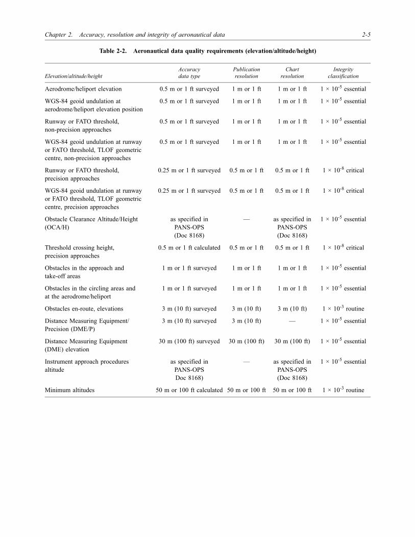
Table 2-2. Aeronautical data quality requirements (elevation/altitude/height)
Elevation/altitude/heightAccuracydata type
Publication resolution
Chartresolution
Integrityclassification
Aerodrome/heliport elevation 0.5 m or 1 ft surveyed 1 m or 1 ft 1 m or 1 ft 1 × 10⁻⁵ essential
WGS-84 geoid undulation at aerodrome/heliport elevation position
0.5 m or 1 ft surveyed 1 m or 1 ft 1 m or 1 ft 1 × 10⁻⁵ essential
Runway or FATO threshold,non-precision approaches
0.5 m or 1 ft surveyed 1 m or 1 ft 1 m or 1 ft 1 × 10⁻⁵ essential
WGS-84 geoid undulation at runway or FATO threshold, TLOF geometric centre, non-precision approaches
0.5 m or 1 ft surveyed 1 m or 1 ft 1 m or 1 ft 1 × 10⁻⁵ essential
Runway or FATO threshold,precision approaches
0.25 m or 1 ft surveyed 0.5 m or 1 ft 0.5 m or 1 ft 1 × 10⁻⁸ critical
WGS-84 geoid undulation at runway or FATO threshold, TLOF geometric centre, precision approaches
0.25 m or 1 ft surveyed 0.5 m or 1 ft 0.5 m or 1 ft 1 × 10⁻⁸ critical
Obstacle Clearance Altitude/Height (OCA/H)
as specified in PANS-OPS(Doc 8168)
— as specified inPANS-OPS(Doc 8168)
1 × 10⁻⁵ essential
Threshold crossing height,precision approaches
0.5 m or 1 ft calculated 0.5 m or 1 ft 0.5 m or 1 ft 1 × 10⁻⁸ critical
Obstacles in the approach andtake-off areas
1 m or 1 ft surveyed 1 m or 1 ft 1 m or 1 ft 1 × 10⁻⁵ essential
Obstacles in the circling areas andat the aerodrome/heliport
1 m or 1 ft surveyed 1 m or 1 ft 1 m or 1 ft 1 × 10⁻⁵ essential
Obstacles en-route, elevations 3 m (10 ft) surveyed 3 m (10 ft) 3 m (10 ft) 1 × 10⁻³ routine
Distance Measuring Equipment/Precision (DME/P)
3 m (10 ft) surveyed 3 m (10 ft) — 1 × 10⁻⁵ essential
Distance Measuring Equipment (DME) elevation
30 m (100 ft) surveyed 30 m (100 ft) 30 m (100 ft) 1 × 10⁻⁵ essential
Instrument approach procedures altitude
as specified in PANS-OPSDoc 8168)
— as specified inPANS-OPS(Doc 8168)
1 × 10⁻⁵ essential
Minimum altitudes 50 m or 100 ft calculated 50 m or 100 ft 50 m or 100 ft 1 × 10⁻³ routine

2-6 World Geodetic System — 1984 (WGS-84) Manual
Table 2-3. Aeronautical data quality requirements (declination and magnetic variation)
Table 2-4. Aeronautical data quality requirements (bearing)
Declination/variationAccuracydata type
Publicationresolution
Chartresolution
Integrityclassification
VHF NAVAID station declination used for technical line-up
1 degree surveyed 1 degree — 1 × 10⁻⁵ essential
NDB NAVAID magnetic variation 1 degree surveyed 1 degree — 1 × 10⁻³ routine
Aerodrome/heliport magnetic variation 1 degree surveyed 1 degree 1 degree 1 × 10⁻⁵ essential
ILS localizer antenna magnetic variation 1 degree surveyed 1 degree — 1 × 10⁻⁵ essential
MLS azimuth antenna magnetic variation
1 degree surveyed 1 degree — 1 × 10⁻⁵ essential
BearingAccuracydata type
Publicationresolution
Chartresolution
Integrityclassification
Airway segments 1/10 degreecalculated
1 degree 1 degree 1 × 10⁻³ routine
En-route and terminal fix formations 1/10 degreecalculated
1/10 degree 1/10 degree 1 × 10⁻³ routine
Terminal arrival/departure route segments
1/10 degreecalculated
1 degree 1 degree 1 × 10⁻³ routine
Instrument approach procedure fix formations
1/100 degreecalculated
1/100 degree 1/10 degree 1 × 10⁻⁵ essential
ILS localizer alignment 1/100 degreesurveyed
1/100 degreeTrue
1 degree 1 × 10⁻⁵ essential
MLS zero azimuth alignment 1/100 degreesurveyed
1/100 degreeTrue
1 degree 1 × 10⁻⁵ essential
Runway and FATO bearing 1/100 degreesurveyed
1/100 degreeTrue
1 degree 1 × 10⁻³ routine

Chapter 2. Accuracy, resolution and integrity of aeronautical data 2-7
Table 2-5. Aeronautical data quality requirements (length/distance/dimension)
Length/distance/dimensionAccuracydata type
Publicationresolution
Chartresolution
Integrityclassification
Airway segments length 1/10 km or1/10 NM calculated
1/10 km or1/10 NM
1 km or 1 NM 1 × 10⁻³ routine
En-route fix formations distance 1/10 km or1/10 NM calculated
1/10 km or1/10 NM
2/10 km (1/10 NM) 1 × 10⁻³ routine
Terminal arrival/departure routesegments length
1/100 km or1/100 NM calculated
1/100 km or1/100 NM
1 km or 1 NM 1 × 10⁻⁵ essential
Terminal and instrument approach procedure fix formations distance
1/100 km or1/100 NM calculated
1/100 km or1/100 NM
2/10 km (1/10 NM) 1 × 10⁻⁵ essential
Runway and FATO length,TLOF dimensions
1 m or 1 ft surveyed 1 m or 1 ft 1 m (AD chart)0.5 m (AOC chart)
1 × 10⁻⁸ critical
Stopway length 1 m or 1 ft surveyed 1 m or 1 ft 0.5 m (AOC chart) 1 × 10⁻⁸ critical
Landing distance available 1 m or 1 ft surveyed 1 m or 1 ft 1 m (AD chart)0.5 m (AOC chart)
1 × 10⁻⁸ critical
ILS localizer antenna — runway end and FATO end, distance
3 m or 10 ft calculated 3 m (10 ft) as plotted 1 × 10⁻³ routine
ILS glide slope antenna — threshold, distance along centre line
3 m or 10 ft calculated 3 m (10 ft) as plotted 1 × 10⁻³ routine
ILS markers — threshold distance 3 m or 10 ft calculated 3 m (10 ft) 2/10 km (1/10 NM) 1 × 10⁻⁵ essential
ILS DME antenna — threshold, distance along centre line
3 m or 10 ft calculated 3 m (10 ft) as plotted 1 × 10⁻⁵ essential
MLS azimuth antenna — runway end and FATO end, distance
3 m or 10 ft calculated 3 m (10 ft) as plotted 1 × 10⁻³ routine
MLS elevation antenna — threshold, distance along centre line
3 m or 10 ft calculated 3 m (10 ft) as plotted 1 × 10⁻³ routine
MLS DME/P antenna — threshold, distance along centre line
3 m or 10 ft calculated 3 m (10 ft) as plotted 1 × 10⁻⁵ essential

2-8 World Geodetic System — 1984 (WGS-84) Manual
Table 2-6. Accuracy and probability
Table 2-7. RNP types
Accuracy expressionOne-dimensional
probabilityTwo-dimensional
probabilityThree-dimensional
probability
Three sigma 99.7% 98.9% 97.1%
Two sigma 95.0% 86.0% 78.8%
One sigma 68.0% 39.3% 19.9%
Probable error 50.0%(0.67 σ)
50.0%(1.18 σ)
50.0%(1.54 σ)
Accuracy RNP 1 RNP 4 RNP 12.6 RNP 20
95% position accuracy in the designated airspace
±1.85 km (±1.0 NM)
±7.4 km (±4.0 NM)
±23.3 km (±12.6 NM)
±37 km (±20.0 NM)

3-1
Chapter 3
THE GLOBAL WGS-84 COORDINATE SYSTEM
3.1 DEFINITION OF THE WGS-84COORDINATE SYSTEM
3.1.1 The World Geodetic System — 1984 (WGS-84)coordinate system is a Conventional Terrestrial System(CTS), realized by modifying the Navy Navigation SatelliteSystem (NNSS), or TRANSIT, Doppler Reference Frame(NSWC 9Z-2), in origin and scale, and rotating it to bringits reference meridian into coincidence with the BureauInternational de l’Heure (BIH)-defined zero meridian.
3.1.2 Origin and axes of the WGS-84 coordinatesystem are defined as follows.
a) Origin is the earth’s centre of mass.
b) Z-axis is the direction of the Conventional Terres-trial Pole (CTP) for polar motion, as defined byBIH on the basis of the coordinates adopted for theBIH stations.
c) X-axis is the intersection of the WGS-84 referencemeridian plane and the plane of the CTP’s equator,the reference meridian being the zero meridiandefined by the BIH on the basis of the coordinatesadopted for the BIH stations.
d) Y-axis completes a right-handed, earth-centred,earth-fixed (ECEF) orthogonal coordinate system,measured in the plane of the CTP equator, 90° eastof the X-axis.
Note.— An illustration of the WGS-84 coordinate systemorigin and axes, which serve also as the geometric centreand the X, Y, and Z axes of the WGS-84 ellipsoid, is givenin Figure 3-1.
3.1.3 WGS-84 is an earth-fixed global referenceframe, including an earth model, and is defined by a set ofprimary and secondary parameters. The primary parameters,given in Table 3-1, define the shape of an earth ellipsoid, its
angular velocity, and the earth mass which is included in theellipsoid of reference.
3.1.4 The secondary parameters define a detailedEarth Gravity Field Model (EGFM) of the degree andorder n = m = 180. The WGS-84 EGFM, throughn = m = 180, is to be used when calculating WGS-84geoid heights, WGS-84 gravity disturbance components,and WGS-84 1° × 1° mean gravity anomalies via sphericalharmonic expansions. Expansions to this degree and order(n = m = 180) are needed to accurately model variations inthe earth’s gravitational field on or near the earth’s surface.The WGS-84 EGFM, through n = m = 41, is moreappropriate for satellite orbit calculation (e.g. GPSnavigation satellites) and prediction purposes.
3.2 REALIZATION OF THE WGS-84COORDINATE SYSTEM
3.2.1 The origin and the orientation of coordinateaxes in WGS-84 are defined by the X, Y, Z coordinates ofthe five GPS monitoring stations (see Figure 3-2).
3.2.2 Historically, the coordinates of the GPS trackingsites have been determined by the use of Dopplermeasurements to the TRANSIT satellite navigation system.Data, observed over long periods, have been processed inorder to derive precise station coordinates. The use ofTRANSIT Doppler measurements in WGS-84 is a goodexample of the practical realization of a reference system.It should be pointed out, however, that errors can spreadinto the procedures used to realize reference frames.
3.3 ACCURACY OF WGS-84COORDINATES
3.3.1 The accuracy, one sigma, (1 σ) of WGS-84coordinates directly determined in WGS-84 by GPS SatellitePoint Positioning, their respective precise ephemerides andground-based satellite tracking data acquired in static mode,

3-2 World Geodetic System — 1984 (WGS-84) Manual
in terms of geodetic latitude φ, geodetic longitude λ, andgeodetic height h, is:
a) horizontal — σφ = σλ = ±1 m (1 σ); and
b) vertical — σh = ±1 ... 2 m (1 σ).
3.3.2 These errors incorporate not only the observa-tional error but also the errors associated with placing theorigin of the WGS-84 coordinate system at the earth’scentre of mass and with determining the correct scale.These absolute values should not be confused with thecentimetre-precision of GPS differential positioning. At thetime WGS-84 was established, only satellite Dopplermeasurements with corresponding accuracy were availableto determine the ground control segment of WGS-84.
3.3.3 The WGS-84 coordinates of a non-satellite-derived local geodetic network station will be less accurate
than the WGS-84 coordinates of a GPS station. This is dueto the distortions and surveying errors present in localgeodetic datum networks, i.e. the lack of a sufficientnumber of properly placed GPS stations collocated withlocal geodetic networks for use in determining thetransformation parameters and the uncertainty introducedby the datum transformation.
3.3.4 The accuracy of ±1 m in the definition ofWGS-84 is sufficient for nearly all air navigationapplications. Additional considerations may be necessary if,for example, satellite-based landing systems down toCategory III are to be used in the future. Precision approachCategory III needs a vertical accuracy of 0.6 m and ahorizontal accuracy of 6.0 m, which cannot be supplied byWGS-84 according to its accuracy definition, but can besupplied, for instance, by International Terrestrial ReferenceFrame (ITRF).
Table 3-1. Parameters of WGS-84
Parameter Abbreviation WGS-84
Semi-major axis a 6 378 137 m
Angular velocity ω 7.292115 × 10⁻⁵ rad s-1
Geocentric gravitational constant (Mass of the earth’s atmosphere included)
GM 398 600.5 km3 s-2
Normalized second degree zonal harmonic coefficient of the gravitational potential
C2,0 –484.16685 × 10⁻⁶
Flattening (derived from C2,0 ) f 1/298.257223563

Chapter 3. The global WGS-84 coordinate system 3-3
FIGURES FOR CHAPTER 3
Figure 3-1. The WGS-84 coordinate system definition
Figure 3-2. Realization of origin and orientation of WGS-84
BIH-defined CTP (1984.0)
ZWGS-84
Earth’scentreofmass
BIH-definedzeromeridian(1984.0)
XWGS-84YWGS-84
ColoradoSprings
Hawaii
Ascencion DiegoGarcia
Kwajalein
Master control stationMonitor stationGround antenna

�������

4-1
Chapter 4
A GUIDE TO OBTAIN WGS-84 COORDINATES
4.1 GENERAL
This chapter is intended to be a guide with “recipes” forusers to produce WGS-84 coordinates. The user of themanual is guided through the steps necessary, dependingon the existence and the quality of aeronautical data, toobtain WGS-84 coordinates. The first question to beanswered is:
Are coordinates of the required accuracy available?
Yes If these coordinates are available in a local referenceframe, then proceed to 4.2 (Scenario 1). If theavailable coordinates have been digitized from maps,then proceed to 4.4 (Scenario 3).
When considering the use of existing data, it isimportant to check and control the coordinates ofnavigation facilities with respect to accuracy andintegrity before transforming them to WGS-84 bymathematical means. One has to keep in mind thatcoordinates in air navigation could be safety-criticaland that high-integrity requirements have to befulfilled. In order to fulfil the quality requirementsfor coordinates, the surveyor must ensure that:
a) point labels have not been interchanged ormisidentified;
b) the coordinates can be verified by aid ofredundant measurements; and
c) the accuracy is predictable and sufficient.
No If coordinates of the required accuracy are notavailable or if, for example, the integrity require-ments cannot be fulfilled, a resurvey with relatedfield work must be performed. The different methodsof performing this resurvey to provide accurateWGS-84 coordinates are explained under 4.3(Scenario 2).
4.2 SCENARIO 1: COORDINATES IN ALOCAL REFERENCE FRAME
ARE AVAILABLE
Two approaches exist to transform coordinates given innational coordinates to WGS-84 coordinates. They aredependent on knowledge of the transformation parametersand the type of coordinate system, and can be used asstand-alone methods or combined.
4.2.1 Checking the type ofcoordinate system
4.2.1.1 Before carrying out a datum transformation,check if the transformation parameters from the localreference frame to WGS-84 are known and answer thefollowing question:
Are all transformation parameters known?
Yes Perform a computational datum transformation byusing the datum transformation formulae (4.2.2 refers)to determine the WGS-84 coordinates. Several soft-ware programmes exist to support this procedure, e.g.the DATUM programme.
Note.— DATUM performs coordinate transformationsbetween a variety of existing geodetic reference frames andWGS-84.
No Use the GPS surveying technique, at known controlstations (covering the area under consideration), toobtain WGS-84 coordinates. Since these controlstations are known in the local reference frame and inWGS-84, two sets of coordinates for identicalstations exist. These can then be used to determinethe datum parameters in the Helmert Formula. Atleast three known control stations have to besurveyed by GPS to obtain additional WGS-84coordinates necessary for determining all sevenHelmert transformation parameters (using the InverseHelmert Formula). In practice, however, it is usual to

4-2 World Geodetic System — 1984 (WGS-84) Manual
have as many common points as possible to obtainthe best estimate of the parameters by least squares.
Note.— See Appendix A for information on GPSsurveying. See Appendix D for a detailed description of theHelmert Formula.
4.2.1.2 For the following example, it is assumed thatonly the shifts of origin between the local reference frameand the WGS-84 have to be determined and that, therefore,only one known control station was GPS-surveyed. Theinverse Helmert Formula for solving the three shift oforigin parameters reads:
Assumption: No change in orientation (εX = εY = εZ = 0)and scale (µ = 1) between the local reference frame andWGS-84.
4.2.1.3 After determining all necessary transformationparameters, proceed as explained at the beginning of 4.2.1.1.The method of referencing a local (i.e. relative) andsufficiently accurate GPS aerodrome survey to WGS-84 bysimply measuring the coordinate differences between oneaerodrome point to a known and monumented WGS-84station is called direct geodetic connection. In applying thisprocedure, all the airport coordinates can be directlytransformed to WGS-84. The problem, however, is that notmany geodetic stations exist worldwide for which accurateWGS-84 coordinates are known. It is therefore recommendedto use, if available, ITRF stations for this purpose. If no ITRFstation is near the aerodrome or navigation facility, theconnection survey can be very laborious. In this case, longdistances have to be traversed by surveying, which could bevery expensive.
4.2.2 Horizontal datum transformations
4.2.2.1 There are three different approaches fortransforming coordinates from a local datum to WGS-84.Use the:
a) Helmert Formula to carry out the transformation inrectangular Cartesian coordinates X, Y, Z, usingthree-, four-, or seven-parameter transformationsdepending on the availability and/or reliability ofthe transformation parameters. The HelmertFormula can also be applied for spatial ellipsoidal
coordinates f, l, h by transforming from ellipsoidalcoordinates to rectangular coordinates and viceversa.
b) Standard Molodensky Formula to solve the trans-formation in curvilinear coordinates f, l, h.
c) Multiple Regression Equation approach to accountfor the non-linear distortion in the local geodeticdatum. (Only recommended for large areas).
Note.— See Appendix D for a detailed description ofthese datum transformation formulae and Table B-1 for alist of reference ellipsoids and parameters.
4.2.2.2 Accuracy considerations
4.2.2.2.1 Because of error propagation, a datumtransformation will never improve the survey accuracy. Inmost cases the accuracy of the transformed coordinates inthe absolute sense is worse than the accuracy of the originalcoordinates. The user has to check, in particular, whetherthe resulting coordinate accuracy still meets the require-ments. Furthermore, this quality control may be difficult toperform.
4.2.2.2.2 Two of the several reasons known for thisloss of accuracy are:
a) because the datum or transformation parametersare, in many cases, only weakly determined, sub-stantial discrepancies of up to 50 m in datumparameters can occur between published valuesfrom different reference sources. Furthermore, theaccuracy of a navigation aid’s original coordinatesmay not be sufficient, and in many cases theaccuracy of the datum parameters is undefined; and
b) there may be a slight distortion in the nationalnetwork in the area under consideration.
4.2.2.3 Limitations of transformations
4.2.2.3.1 It should be noted that random andsystematic errors in local survey data transform directly toWGS-84. Because of geodetic network geometry and errorpropagation in these networks, the local datum parametersfor a State are not constant in practice but vary withlocation in the geodetic network.
4.2.2.3.2 The signal-to-noise ratio for the datumparameters is, in many cases, close to one, i.e. the noiselevel is very high relative to the magnitude of the datum
Shift oforigin
ΔXΔYΔZ
XYZ WG 84–
XYZ Local
–=
WGS-84 Local

Chapter 4. A guide to obtain WGS-84 coordinates 4-3
parameter itself. For example, the orientation angles of adatum could be published, typically as, say, 0.5" ± 0.3".
4.2.2.3.3 The predicted error, or uncertainty, is oftenlarger than the value itself. Figure 4-1 shows, in aqualitative manner, how the errors in transformationprocedures propagate into transformed coordinates.
4.2.2.3.4 The error sources in a datum transformationare errors in the shift parameters, the orientation parametersand the scale factor. The scale factor error is incorporatedin the above in that it is treated like an orientation error, inradians, applied to the coordinate value to be transformedby multiplication. Even an accurate survey with an internalaccuracy of, say, 0.1 m may show, after the transformationparameters have been applied, only 1 m level accuracy inWGS-84. Here the difference between absolute and relativepoint accuracy has to be considered.
4.3 SCENARIO 2: COORDINATES OF THEREQUIRED ACCURACY ARE
NOT AVAILABLE
4.3.1 New field survey techniques
4.3.1.1 If coordinates of the required accuracy are notavailable, a new field survey must be performed using one,or a combination of, the following techniques:
a) conventional surveying;
b) GPS surveying; or
c) photogrammetric surveying.
4.3.2 Best technique(s) for new field survey
4.3.2.1 In deciding which of the above techniques is(or are) the most efficient for the new field survey, thefollowing may be used as guidance.
a) Use the GPS technique for surveying limited andrelatively small areas in a very economical way.
b) Use the photogrammetric technique if the area to besurveyed is very large.
c) Use conventional surveying if the area to besurveyed contains many obstructions which wouldlead to GPS signal losses or multipath.
Note.— There is no doubt that a complete resurvey ofthe point using differential GPS satellite surveyingtechniques (relative to a known station with WGS-84coordinates) is the most accurate approach for determiningprecise WGS-84 coordinates.
4.3.3 Determination byconventional terrestrial surveying
4.3.3.1 Figure 4-2 shows how WGS-84 coordinatescan be obtained by conventional terrestrial surveying.
4.3.3.2 Some of the conventional surveyinginstruments of modern type (levelling instrument, theodolite,distance meter, total station) have interactive fieldcomputational capabilities. After downloading the data viaan interface into an office computer, final post-processingcould be carried out. Before the derived coordinates canenter the survey database, they have to be quality-controlled,and integrity checks have to be performed. Various graphicvisualizations of data and results can also be done.
Note.— For more information on conventionalsurveying, see Appendix E.
4.3.4 Determination byGPS surveying
4.3.4.1 Most of the field surveying which is necessaryfor the positioning of navigation aids, radars, runways, etc.,is best carried out by differential GPS satellite surveying.This method has the advantages of 24-hour all-weatheroperations, ease of use, speed, economy, high accuracy and,most importantly, direct compatibility with the WGS-84datum.
4.3.4.2 GPS receivers store the field data. Afterfinishing the survey, the data have to be downloaded to acomputer where they are post-processed using softwarepackages provided by GPS hardware manufacturers and/oruniversities. The processing can be done either by individualbaseline or in a multisession-multistation network approach.Again, before the derived coordinates can enter the surveydatabase, they have to be quality-controlled, and integritychecks have to be performed. Various visualizations of dataand results can also be performed.
Note.— For the choice of the GPS surveying technique,(static, rapid static, kinematics survey, etc.) which dependsto a great extent on the desired accuracy, see Appendix Aand Table A-2.

4-4 World Geodetic System — 1984 (WGS-84) Manual
4.3.5 Determination byaero-photogrammetry
4.3.5.1 Figure 4-3 shows the determination ofWGS-84 coordinates by using photogrammetric flights.The parameters of the photogrammetric flight have to bedetermined as a function of anticipated coordinate accuracyof the ground stations. If no WGS-84 coordinates at groundstations are available, they have to be established usingGPS differential surveying techniques. Thus, a network ofground control points whose coordinates and heights areknown in advance is an essential requirement forreferencing the newly derived coordinates to a nationaldatum. The points to be coordinated have to be marked sothat a unique identification in the aerial photos is possible.
4.3.5.2 If necessary, permission must be obtained torelease photo data. These data are then developed and thestereo model construction is carried out in a photo-grammetric instrument in the office. After inputting theground control coordinates and, if available, GPS-derivedcamera positions, the data are processed by a bundle blockadjustment.
4.3.5.3 Again, before the derived coordinates canenter the survey database, they have to be quality-controlled, and integrity checks have to be performed.Various visualizations of data and results can then be done.
Note.— For more information on aero-photogrammetryand the minimization of ground control stations, seeAppendix E.
4.4 SCENARIO 3: COORDINATES DIGITIZEDFROM MAPS ARE AVAILABLE
Note.— This section helps the user transformcoordinates to WGS-84, if the coordinates are availablefrom digitized maps.
4.4.1 Restrictions
4.4.1.1 While digitized data have no inherent scaleinformation, the accuracy of the data is clearly limited bythe corresponding accuracy of the analogue map fromwhich the data were originally extracted and of thedigitizing process involved. A new analogue map may beprinted using a larger scale than that of the original map,but this does not increase the accuracy to the level normallyassociated with the larger scale. The problem is furthercompounded by the frequent revision and updating of thedatabase with newly surveyed field data. Furthermore, the
digitizing process involves the straightening and squaringof regular objects, leading to apparently “well drawn” mapseven after the enlargement process.
4.4.1.2 The most important drawback of digitizedmaps, however, is the very nature of an analogue database.High-precision mapping coordinates are generally given innational grid northings and eastings, which have beenobtained by converting geodetic (ellipsoidal) coordinatesinto a map projection. In addition, one must consider themore significant projection scale and orientation errorsinherent in all map projections. While these can be reducedby the judicious use of an orthomorphic projection (e.g.Transverse Mercator), they are still substantial, renderingthe process of extracting coordinate information from amap precarious. For example, if the grid coordinates of twopoints are extracted from the map and the grid distancecomputed, the distance would be up to 30 cm per kilometreshorter than the value measured on the ground. This issignificant and may have serious implications.
4.4.1.3 Therefore, when digitizing coordinates frommaps, the following points should be considered:
a) It is necessary to check by which technique the mapwas established (from analogue data/digitizing ofother maps, from digital data, etc.).
b) In order to convert the northings and eastings togeographical coordinates, it is necessary to knowthe exact formulae of the map projection.
c) It is necessary to know the original datum of theprojected coordinates as well as the new one, whentransforming.
d) Datum coordinate transformation can only beapplied after converting map projection coordinatesto geodetic coordinates.
e) The resulting accuracy of digitized coordinatesshould be checked and verified in order to decidewhether the anticipated accuracy requirements havebeen met.
4.4.1.4 WGS-84 is the definition of the centre of massof the Earth as determined in 1984 and all charts producedprior to that date using a different geodetic reference willnot correspond exactly to new charts based on WGS-84.Finally, one has to bear in mind that maps never containellipsoidal heights. For example, heights in different mapsmay refer to:
a) different zero points (tide gauges); or

Chapter 4. A guide to obtain WGS-84 coordinates 4-5
b) different types of height systems. (There are notonly orthometric heights, but also so-called normalheights, for example, in Eastern Europe.)
4.4.2 Transformations
4.4.2.1 To transform coordinates digitized from mapsto WGS-84, it is essential to answer the following question:
Is the kind of map projection, which was used in the localsurvey for mapping the reference ellipsoid to the plane andfor computing the plane metric coordinates, known?
No If this question cannot be answered or the projectionis not known, then Scenario 2 applies and a resurveyshould be performed.
Yes If the type of map projection is known, the inversemap projection has to be calculated to computelatitude and longitude of the digitized metriccoordinates on the reference ellipsoid.
Note.— See Appendix F for different types of mapprojections.
4.4.2.2 All datum transformations require the use ofthe ellipsoidal height h in the local system, which is:
h = H + N
where H is the orthometric height (elevation) and N is thegeoid undulation (height). In general, only the orthometricheight is known (and found also on maps). The geoidundulation has to be taken from a digital model (ifavailable). However, an investigation was made checking theeffect of an unknown (orthometric) height on thetransformed latitude and longitude of a point using theHelmert Formulae. By assigning heights ranging from 0 mto 8 000 m, it was concluded that the effect on both latitudeand longitude was negligible (less than 15 cm at 8 000 m).Consequently, for a point of known latitude and longitudebut unknown (orthometric) height, an arbitrary height of 0 mcould be assigned without significantly affecting thetransformation.
4.4.2.3 Because national surveying agencies are usingdifferent kinds of reference ellipsoids, the next step is todetermine which reference ellipsoid is being used in orderto perform the datum transformation from the local datumto the global datum. Sometimes it may be possible totransform directly from the local datum to WGS-84. If not,then a further transformation from the global datum toWGS-84 has to be undertaken.

4-6 World Geodetic System — 1984 (WGS-84) Manual
FIGURES FOR CHAPTER 4
Figure 4-1. Error propagation in datum transformation
Figure 4-2. From terrestrial surveying data to WGS-84 coordinates
0
0 10 20 30 40 50
010203040506070
Datumshift error
[ m ]
Datumorientation
error[ " ]
Coordinatetransformation
error[ m ]
0.1 0.
3 0.4 0.
5
0.2
Distance meter
Some instrumentshave interactive
field computationcapabilities
Field data
LevellingTheodolite
Total station
Downloadingfield data
Postprocessing
WGS-84coordinatesnew stations
Referencestation data

Chapter 4. A guide to obtain WGS-84 coordinates 4-7
Figure 4-3. From results of photogrammetric flights to WGS-84 coordinates
Aerial photosGPS data
Release/permission
Photo development
Stereo model construction
(GPS) dataprocessingGround control
Coordinates in WGS-84
Photocamera
AttitudeGPS

�������

5-1
Chapter 5
SURVEYING GUIDANCE
5.1 INTRODUCTION
This chapter sets out guidance for surveying thegeographical positions of navigation aids and navigationpoints brought about by the adoption of WGS-84 as acommon geodetic reference frame for international civilaviation. The particular accuracy of the field work valueshas been based on operational requirements and is inaccordance with the provisions set forth in Annexes 11 and14, Volumes I and II while resolutions requirements are setforth in Annexes 4 and 15. The specified accuracies can,in many cases, easily be exceeded using modern surveyinstrumentation.
5.1.1 Application ofrequirements
5.1.1.1 The requirements contained in this chapterapply to all aerodromes/heliports selected by nationaladministrations for international and domestic use and theyrelate to the surveying, with respect to WGS-84, of thegeographical coordinates of navigation elements. Thosenavigation aids and points whose coordinates contributedirectly to air navigation are considered in this chapter asnavigation elements. Surveying guidance covers the deter-mination of coordinates, i.e. latitudes and longitudes ofcertain navigation positions.
5.1.1.2 The results of the surveying of WGS-84-related geographical positions of navigation elements mustbe reported to the aeronautical information service of thenational administration, in accordance with the provisionsin Annexes 11 and 14.
5.1.1.3 This chapter includes surveying requirementsfor those aerodrome/heliport positions, such as designatedaircraft stands and navigation checkpoints, whose coordi-nates may be used for the purpose of checking, calibratingor initializing navigation equipment. The list of navigationelements to be surveyed is given in Table 5-1.
5.2 GENERAL SPECIFICATIONS
5.2.1 The geodetic datum to which coordinates ofnavigation elements must be referenced is WGS-84. Thisrequirement will be achieved by surveying with respect toan appropriate global geodetic reference frame.
5.2.2 All aeronautical coordinate data which meetthe specifications of this manual must be such that theirquality can be demonstrated. The accuracy of the fieldwork, with respect to determination of the geographicalcoordinates of the various navigation elements, has beenset in accordance with both current and anticipatedoperational requirements. Where a navigation aid servesmore than one phase of flight and is thereby subject todifferent operational requirements, the more stringentsurveying accuracy requirement must apply.
5.2.3 All position accuracies must relate to a probabilityof 95% (2 σ) containment unless otherwise stated. Units ofmeasurement must be in accordance with the survey customand practice of the particular State. All published geographi-cal positions and dimensions must be in accordance withICAO requirements. In this regard, geographical positionsmust be published in the form of sexagesimal degrees(degrees, minutes, seconds and decimals of a second) and tothe publication resolutions in Annex 15, Appendix 7 and thecharting resolutions in Annex 4, Appendix 6.
5.2.4 Dimensions and distances must be quoted in oneof the following units:
a) metres (m);
b) feet (1 ft = 0.3048 m); or
c) nautical miles (1 NM = 1 852 m).
5.2.5 Aerodrome/heliport surveycontrol network
In order to determine the position of navigation elements at,and in the vicinity of, designated aerodromes/heliports, a

5-2 World Geodetic System — 1984 (WGS-84) Manual
network of survey control stations must be established at eachsuch aerodrome/heliport. The network must consist of aminimum of two inter-visible survey stations at a minimumlateral separation of 500 m. The aerodrome/heliport surveycontrol network may consist of a minimum of four stations so asto provide sufficient redundancy to be able to sustain the loss ofone survey station and still enable the orientation to be checked.Survey stations must be strategically located so as to providemaximum utility in subsequent surveys. The monuments ofexisting aerodrome/heliport survey control networks may be usedfor the purposes laid down in this chapter.
5.2.6 Control networkaccuracy requirements
5.2.6.1 The position of each survey station must bedetermined to an accuracy of 1 m with respect to anappropriate geodetic reference frame. The control networkmust have an internal accuracy consistent with the need toprovide control for the survey of navigation elements tothe accuracies set out in the relevant Annexes and in thischapter. The aerodrome/heliport survey control networkmay have an internal consistency of better than 10 cm.
Table 5-1. Minimum survey accuracy and integrity requirements for navigation elements
Note.— Accuracies are those relative to the established aerodrome/heliport survey control network except where markedby an asterisk (*) when they relate to absolute coordinates with respect to the datum.
Latitude and longitudeAccuracydata type
Integrityclassification
En-route NAVAIDS and fixes, holding, STAR/SID points 100 m surveyed/calculated 1 × 10⁻⁵ essential
Aerodrome/heliport reference point 30 m surveyed/calculated 1 × 10⁻³ routine
NAVAIDS located at the aerodrome/heliport 3 m surveyed 1 × 10⁻⁵ essential
Obstacles in the circling area and at the aerodrome/heliport 3 m surveyed 1 × 10⁻⁵ essential
Significant obstacles in the approach and take-off area
3 m surveyed 1 × 10⁻⁵ essential
Final approach fixes/points and other essential fixes/points comprising instrument approach procedure
3 m surveyed/calculated 1 × 10⁻⁵ essential
Runway (landing) threshold 1 m surveyed 1 × 10⁻⁸ critical
Runway end(flight path alignment point)
1 m surveyed 1 × 10⁻⁸ critical
Runway centre line points 1 m surveyed 1 × 10⁻⁸ critical
Taxiway centre line points 0.5 m surveyed 1 × 10⁻⁵ essential
Ground taxiway centreline points, air taxiways and transit routes points
0.5 m surveyed/calculated 1 × 10⁻⁵ essential
Aircraft standpoints/INS checkpoints 0.5 m surveyed 1 × 10⁻³ routine
Geometric centre of TLOF or FATO thresholds at heliports 1 m surveyed 1 × 10⁻⁸ critical
WGS-84 geoid undulation at aerodrome/heliport elevation position 0.5 m or 1 ft surveyed 1 × 10⁻⁵ essential
WGS-84 geoid undulation at runway or FATO threshold, TLOF geometric centre, non-precision approaches
0.5 m or 1 ft surveyed 1 × 10⁻⁵ essential
WGS-84 geoid undulation at runway or FATO threshold, TLOF geometric centre, precision approaches
0.25 m or 1 ft surveyed 1 × 10⁻⁸ critical
Aerodrome/heliport survey control network (datum transfer) 1 m * surveyed 1 × 10⁻⁸ critical

Chapter 5. Surveying Guidance 5-3
5.2.6.2 Mathematical transformation methods basedon a single set of average transformation parameters, whichrelate known (existing) datum to WGS-84, must not beused for the purpose of determining the coordinates of theaerodrome/heliport survey control network.
5.2.7 Monumentation of surveycontrol stations
The survey control stations must consist of standard typesof survey monuments (see Attachment A to this chapter).Different types of monuments will be appropriate fordifferent locations and ground conditions at the aerodrome/heliport; it is the surveyor’s responsibility, under theguidance of the national administration, to decide on themost appropriate type. Investigation may be made prior tothe installation of a survey monument to ensure thatunderground cables and services are not affected by theinstallation. Where the survey network consists of fewerthan the recommended four stations, monuments of alarger size must be used.
5.2.8 Station numbering
5.2.8.1 Each survey station must carry an individualnumber. This will ensure that, where a station has beendestroyed and subsequently replaced by a new station inapproximately the same location, misidentification does notoccur.
5.2.8.2 Station labelling and numbering must be suchthat there is no doubt as to the provenance or identity of thesurvey station. Uniform labels (e.g. stamped disks) may beused at individual aerodromes/heliports for all surveystations. An unambiguous numbering system, identifyingthe aerodrome/heliport, year and station number, may beused (see Attachment A to this chapter). Where an existing,substantial topographic surface feature is used as a surveystation, the station must be clearly marked with durablepaint.
5.2.9 Station location plan
An aerodrome/heliport survey network plan, at a scale of1:2 000 or other appropriate standard cartographic scale,indicating the location of all survey stations and principaltopographic features must be prepared. The plan may beorientated to true north or, alternatively, have the directionof true north indicated on the plan.
5.2.10 Station descriptions
5.2.10.1 A comprehensive aerodrome/heliport surveynetwork station description must be prepared. This mustconsist of a written description and a clear diagramindicating the dimensions and direction indicators to othervisible points on the aerodrome/heliport survey controlnetwork.
5.2.10.2 A photograph of the station showingbackground detail may be included in the description.Inspections may be made to check on the general conditionof the aerodrome/heliport survey network, and anydisturbance or damage must be recorded.
5.2.11 Determination of control coordinates
5.2.11.1 One of the following methods of coordinatedetermination must be used to fix the positions of theaerodrome/heliport survey control network.
a) Direct geodetic connection. Survey measurementsmust be taken to connect the aerodrome/heliportsurvey control network to a national or international(e.g. ITRF) geodetic frame in such a way that thesurvey error in the connection does not contributesignificantly to the coordinate error of the aerodrome/heliport survey control network. This is the preferredoption, in that it consists of the most accurate methodof observation and incorporates a directly observedconnection to the approved geodetic reference frame.Static differential GPS connections may be made to,preferably, three points on an appropriate geodeticnetwork but, in all cases, must be made to a minimumof two.
b) Derived geodetic connection. Where the localrelationship between the existing geodetic controlnetwork and WGS-84 is known to an accuracycommensurate with the requirements in thismanual, then standard, nationally or regionallyapproved transformation methods may be used todetermine the coordinates of an existing aerodrome/heliport survey control network. Where this methodis adopted, a full description of the transformationmethod and the values of the transformationparameters must be included in the report. Fulldetails of the connection of the existing aerodrome/heliport survey control network to the existinggeodetic network must be included in the surveyreport (an existing network means one that existedat the aerodrome/heliport prior to the implemen-tation of WGS-84 at that aerodrome/ heliport).

5-4 World Geodetic System — 1984 (WGS-84) Manual
c) Direct observation of WGS-84. For those regionswhere national or international coordinates areunavailable, the coordinates of the aerodrome/heliport survey control network must be determinedby direct observation of WGS-84 by using anappropriate type of geodetic GPS receiver. All suchobservations must be controlled by simultaneousobservations made at points of known absoluteWGS-84 coordinates. The observation and compu-tation method must be such that the absolutecoordinates of the aerodrome/heliport survey controlnetwork are determined to the accuracy stated in thischapter.
5.2.12 Determination of the localrelationship between the known
existing datum and WGS-84
5.2.12.1 Where existing relative surveys need to berelated to WGS-84 (e.g. aerodrome/heliport obstaclesurveys), observations must be taken to determine the localrelationship (difference in latitude, longitude, orientationand scale) between the known existing datum and WGS-84,except where the required information is provided by aderived geodetic connection.
5.2.12.2 Where used, the local relationship betweenthe known existing geodetic datum and WGS-84 must bedetermined to an accuracy commensurate with the relativeaccuracy of the data to be transformed. The values andaccuracies of the local relationship must be declared in thesurvey report.
5.2.13 Report requirements
5.2.13.1 All survey work undertaken to determine thecoordinates of navigation facilities at aerodromes/heliportsmust be reported in the format specified in Attachment C tothis chapter. Where an existing national reporting practicediffers from that shown in this chapter, the nationaladministration may make a case in support of the nationalpractice, where the national practice can be shown to becompatible.
5.2.13.2 Table 5-1 lays down the minimum surveyaccuracies that must be achieved. These accuracies can, inmany cases, easily be exceeded using modern surveyinstrumentation. All survey observations may be made andrecorded to the resolution and accuracy of the equipmentused so that future requirements for surveys of greaterprecision might be met. Where surveys are undertaken usingequipment or techniques that yield height data as well ashorizontal position, these must be comprehensively recordedand included in the survey report.
5.3 SURVEY REQUIREMENTS FORAERODROME/HELIPORT-RELATED
NAVIGATION ELEMENTS
5.3.1 Runway centre lines and thresholds
5.3.1.1 For surveying purposes, the centre line of arunway must be taken as being the geometric centre of thewidth of the bearing surface, this definition taking precedenceover any existing runway centre line markings or lighting.Where the edge of the runway is irregular or connected to ataxiway, an appropriate theoretical line must be selectedwhich best identifies the probable edge of the runway.
5.3.1.2 For surveying purposes, threshold positionsmust be taken as being at the geometric centre of the runwayand at the beginning of the paved surface, i.e. the beginningof that portion of the runway usable for landing. Wherethresholds are marked by appropriate threshold markings(e.g. displaced thresholds), these must be taken as thethreshold points. Where threshold lighting is surveyed, thelocations must be described on the diagram accompanyingthe report. Where there is no threshold lighting, the surveyormust select an appropriate point for survey in accordancewith the diagrams shown in Attachment B to this chapter.
5.3.1.3 If the runway has only one threshold certifiedfor landing, the runway end position must be surveyed. Forsurveying purposes, the runway end position (flight pathalignment point) must be taken as being at the geometriccentre of the runway and at the end of the paved surface,i.e. the end of that portion of the runway usable for landing.
5.3.1.4 Survey witness marks must be installed toenable the threshold survey point to be re-established in theevent of resurfacing, repainting or verification. In addition,two associated runway centre line points, at a separation ofnot less than 10% of the runway length, must be surveyed.The surveyor must, in processing the survey data, determineand report on the collinearity of the three points. Where arunway has a threshold at each end, then the two thresholdsand the two additional runway centre line points may besurveyed, the collinearity then being determined for thegroup of four points.
5.3.2 Derived threshold coordinates
5.3.2.1 Where a point has been selected for surveywhich is not coincident with the runway threshold but offsetalong the centre line, then the coordinates of the thresholdmust be determined by the national administration. Onemethod of calculation for this task is shown in Attachment Dto this chapter.

Chapter 5. Surveying Guidance 5-5
5.3.2.2 The newly derived threshold coordinates mustbe submitted to the same collinearity check as specified in5.3.1.4.
5.3.3 Taxiways and stand/checkpoints
5.3.3.1 General guidelines
5.3.3.1.1 In accordance with the operationalrequirements for advanced surface movement guidance andcontrol systems (A-SMGCS), pilots should be providedwith continuous guidance and control during the landingroll-out, taxiing to the parking position and from theparking position to the runway holding point to line up foran appointed take-off position, and during the take-off roll.
5.3.3.1.2 Since determination of the appropriatetaxiway centre line points and aircraft stand points for pilotguidance and control are predicated on the aerodrome/heliport surface markings, application of the followingparagraphs must be restricted to those aerodromes/heliportsthat conform to the SARPs for markings included inAnnex 14, Volume I, 5.2 and Volume II, 5.2.11 and 5.2.12.
5.3.3.1.3 Diagrams depicting appropriate points onaerodrome/heliport movement areas are shown inAttachment B to this chapter.
5.3.3.1.4 Except as provided in 5.3.3.2.1, forsurveying purposes the centre (mid-width) of the taxiwaycentre line marking, apron taxilane marking or the aircraftstand guide line marking must be taken as the referencedatums. Survey witness marks must be installed to enablethe taxiway centre line, apron taxilane and aircraft standguide line marking survey points to be re-established in theevent of resurfacing or repainting, and for verificationpurposes.
5.3.3.1.5 The points of commencement and ends ofstraight sections of taxiways, apron taxilanes and aircraftstand point guidance lines markings must be surveyed.Sufficient additional points must be surveyed to maintainthe required accuracy along the lines.
5.3.3.1.6 For curved sections of taxiways, aprontaxilanes and aircraft stand guide line markings, thecommencement and end of the curved section centre linemust be surveyed together with the position of the centrepoint of the arc and its radius. In the case of a compoundcurve, the centre and radius of each arc and the commence-ment and end of each of the arcs must be surveyed. Wherethis is impracticable in the field, a series of sequential pointsmust be surveyed along the curved section of the centre linewith a maximum arc to chord distance not exceeding 0.25 mfor taxiways and 0.10 m for apron taxilanes and aircraft stand
guide line markings. Sufficient points must be surveyed tomaintain the required accuracy along the lines. The surveyormust, in processing the data, conduct a graphical inspectionof the survey points to ensure collinearity.
5.3.3.2 Taxiways
5.3.3.2.1 Annex 14, Volume I, 5.2.8.5 and Figure 5-6recommend that taxiway markings on the runway are offsetby 0.9 m parallel to the runway centre line and associatedrunway centre line marking to enable pilots to visuallydistinguish between the runway centre line markings andtaxiway markings for exits from the runway. However, topermit uninterrupted transition from the actual runway centreline to the taxiway centre line and to provide the requiredcontinuity of guidance for the aircraft navigation data base,differentiation must be made between the surface markingsand the actual path the aircraft must follow. Therefore, forthe guidance of aircraft entering or exiting the runway fortake-off or landing, the following must be surveyed:
a) the point at which the radius of turn, prescribed bythe appropriate authority for each taxiway, istangential to the runway centre line (as determinedunder 5.3.1.1) and the point at which that radius ofturn joins the taxiway centre line marking at atangent;
b) the point that prescribes the centre of the arc; and
c) the radius of the arc.
Where this is impracticable in the field, a series of sequentialpoints must be surveyed along the curved section of thecentre line of taxiways.
5.3.3.2.2 Where taxiway centre line marking isprovided on a runway that is part of a standard taxi route,or a taxiway centre line is not coincident with runwaycentre line, the following points must be surveyed:
a) the point on the taxiway marking at which thetaxiway enters the runway;
b) the points at which the taxiway deviates from astraight line;
c) the intersection of the taxiway centre line markingand boundary of each “block” that has beenpublished as part of the airport movement andguidance control system; and
d) the point on the taxiway marking at which thetaxiway exits the runway.

5-6 World Geodetic System — 1984 (WGS-84) Manual
5.3.3.2.3 In defining taxiways, the following pointsmust be surveyed at the centre of the centre line marking ofeach taxiway, as appropriate:
a) intermediate holding positions and runway holdingpositions (including those associated with theintersection of a runway with another runway whenthe former runway is part of a standard taxi route)and for points established for the protection ofsensitive areas for radio navigation aids;
b) taxiway intersection markings;
c) intersection of other taxiways, including taxiwaysdescribed in paragraph 5.3.3.2.2;
d) intersections of “blocks” defined for surfacemovement, guidance and control systems;
e) commencement and end of selectable taxiwaylighting systems provided as part of the surfacemovement, guidance and control systems, wheredifferent from subparagraph d) above; and
f) at stop bars.
5.3.3.2.4 In defining a helicopter air taxiway, thecentre of each air taxiway marker must be surveyed, asappropriate.
5.3.3.3 Aircraft standpoints
5.3.3.3.1 In defining the aircraft stands, the followingpoints must be surveyed at the centre of the guide linemarking of the aircraft stands, as appropriate:
a) taxilane centre lines;
b) lead-in line(s);
c) turning line;
d) straight section of the turning line;
e) nosewheel stopping position;
f) true heading of the alignment bar; and
g) lead-out line(s).
5.3.3.3.2 Where aircraft stands are utilized by morethan one aircraft type and different guide line markingsexist, a diagram must be prepared by the surveyor showingthe arrangement of the markings in use, together with anindication of the points surveyed. Where all the stands at an
aerodrome/heliport are marked uniformly, only a singlediagram need be prepared.
5.3.4 Navigation checkpoints
Where navigation checkpoints used for the validation ofnavigation systems are surveyed, their coordinates must bedetermined to the accuracy laid down in Table 5-1. Wherethese checkpoints coincide with aircraft stands, thenosewheel stopping position must be surveyed in accordancewith 5.3.3.3.
5.3.5 Road holding positions
In accordance with local requirements, significant pointsshall be surveyed to meet the needs of the surfacemovement guidance and control system for vehicular trafficon the movement area of the aerodrome.
5.3.6 All other aerodrome/heliportnavigation elements
For all other aerodrome/heliport navigation elements thatrequire surveying, the geometric centre of the element mustbe surveyed except where a different specific survey point isstandardized for the element, as indicated in Attachment B tothis chapter.
5.4 AERODROME/HELIPORTSURVEY REPORT REQUIREMENTS
All survey work undertaken to determine the coordinates ofnavigation elements at aerodromes/heliports must be reportedin the format laid out in Attachment C to this chapter. Wherean existing national reporting practice differs from thatshown in this chapter, the national administration may makea case in support of the national practice, where the nationalpractice can be shown to be compatible.
5.5 SURVEY REQUIREMENTS FORNAVIGATION AIDS
5.5.1 En-route and aerodrome/heliport navigation aids
5.5.1.1 The coordinates of en-route and aerodrome/heliport navigation aids must meet the accuracy requirementsspecified in Table 5-1. Where existing coordinates of
Chapter 5. Surveying Guidance 5-7
navigation aids that meet the accuracy and integrityrequirements are converted to WGS-84 mathematically, theconversion process must be shown to be such that therequired coordinate accuracies are maintained.
5.5.1.2 Where the quality (for surveying purposes thisrelates to accuracy and integrity requirements) of existingcoordinates cannot be determined, they must be surveyed tothe accuracy specified in Table 5-1. In all cases, surveyedcoordinates may be published in preference to coordinatesdetermined by graphical methods.
5.5.2 Description of en-route andaerodrome/heliport navigation aids
The diagrams of the most common en-route and aerodrome/heliport navigation aids are shown in Attachment B to thischapter. For navigation aids not described in Attachment B,the position of the geometric centre of the antenna must besurveyed. Where collocated VOR/DME are surveyed, theposition of the DME element must be taken as the positionfor both systems.
5.6 EN-ROUTE SURVEYREPORT REQUIREMENTS
All survey work undertaken to determine the coordinates ofen-route navigation elements must be reported in the format
specified in Attachment C to this chapter. Where an existingnational reporting practice differs from that shown in thischapter, the national administration may make a case insupport of the national practice, where the national practicecan be shown to be compatible.
5.7 USE OF SOFTWARE
Where software is used for any of the survey processing, itmust be demonstrated that it functions correctly. Thisdemonstration must take the form of a written reportshowing that the software produces the same results asstandard computation.
5.8 DIGITAL FORMATFOR THE DELIVERY
OF SURVEY DATA
A digital format for the delivery of survey data is includedin Chapter 7. This format may be used for the delivery indigital form of all survey data. Where a national standardpredates the format in Chapter 7 or where the State prefersits own format, the relationship between the two formatsmust be described in detail.
– – – – – – – – – – – –

5-8 World Geodetic System — 1984 (WGS-84) Manual
Attachment A. MONUMENTATION
1. GENERAL
Where survey markers are installed, they must be of a typeappropriate for the task and for the surface and ground typein which they are installed. Designs of suggested surveymarkers are shown in Figures 5A-1, 5A-2 and 5A-3, butother types of markers may be equally appropriate.
2. NUMBERING SYSTEM FORSURVEY MARKERS
2.1 Each survey control point that forms part of theaerodrome/heliport survey control network may be markedin the field with a unique identification number.
2.2 The system of numbering may include theaerodrome/heliport identifier, the station identifier and theyear of establishment. Although the aerodrome/heliportidentifier will be the same for each station at that aerodrome/heliport and, therefore, will serve no local purpose, itsinclusion is important for identification purposes in digitaldatabases.
2.3 Station identifiers, whether alphabetic or numeric,may be assigned chronologically with the construction ofthe station. The inclusion of the year allows the time ofestablishment to be referenced and lessens confusion wherereplacement stations have been established. Alternatively, asimple consecutive numbering system can be used.
2.4 While numbering systems will vary from State toState, it is important that each system include a meanswhereby the stations are not confused with other surveymarkers being established at the same aerodrome/heliport.A simple consecutive numbering system alone, withoutother identifiers, would not be suitable.
Example:
Aerodrome/heliport ICAO location indicator
Station identifier
Year of establishment
LYBE — C — 2001

Chapter 5. Surveying Guidance 5-9
FIGURES FOR ATTACHMENT A
Figure 5A-1. Survey marker
PLAN FULL SIZE
CROSS SECTION FULL SIZE
Road pin
Pin surrounded by 200 mm square of white paint on paved surface
Aluminium disc
40 mm diameter aluminium disc with centre hole to suit road pin diameter
Area of white paint
100 mmminimum
Road pin

5-10 World Geodetic System — 1984 (WGS-84) Manual
Figure 5A-2. Survey marker
SV coverBevelled top withcentre punchnail at top
10 mm diameter stainless steel rod 100 mm long fitted through pre-drilled hole in 20 mm diameter (vertical) rod
Compressiblefiller 25 mmthick minimum
Concrete500 x 500 mmon plan
20 mm diameterstainless steelrod 600 mm long
Trial pitback filledwith concrete

Chapter 5. Surveying Guidance 5-11
Figure 5A-3. Survey marker
– – – – – – – – – – – –
Fine mark cross
Optionalconcrete collar
Steel or alloy tube
Length to be agreed according to ground conditions. The illustration is diagrammatic only and is not intended
to refer to any particular proprietary type.
Ground surface

5-12 World Geodetic System — 1984 (WGS-84) Manual
Attachment B. DESCRIPTION OF GEOGRAPHICAL POSITIONS
In order to standardize the determination of threshold positionsfor survey purposes, the following guidance is provided:
a) diagrams most closely representing the runwaymarkings may be selected and used as the basis fora description of the location of the markings (lights)and the positions selected for survey;
b) where none of the diagrams in this attachment areappropriate, a new diagram must be prepared,
showing the actual arrangement of the markingsand the positions selected for survey;
Note.— Wing-bar threshold lights and lightsinstalled ahead of the runway hard surface have nodirect survey status with respect to thresholds.
c) where existing national standards are used, thesurvey report must indicate the equivalence to thediagrams shown in this attachment.

Chapter 5. Surveying Guidance 5-13
FIGURES FOR ATTACHMENT B
Figure 5B-1. Threshold planimetric position to be surveyed
Thresholdposition
to survey
Thresholdposition
to survey
Thresholdposition
to survey
1/2 w
1/2 w 1/2 w
1/2 w 1/2 w

5-14 World Geodetic System — 1984 (WGS-84) Manual
Figure 5B-2. Threshold planimetric position to be surveyed
1/2 w
W
W W
Thresholdposition
to survey
1/2 w
Thresholdposition
to survey
Thresholdposition
to survey
1/2 w
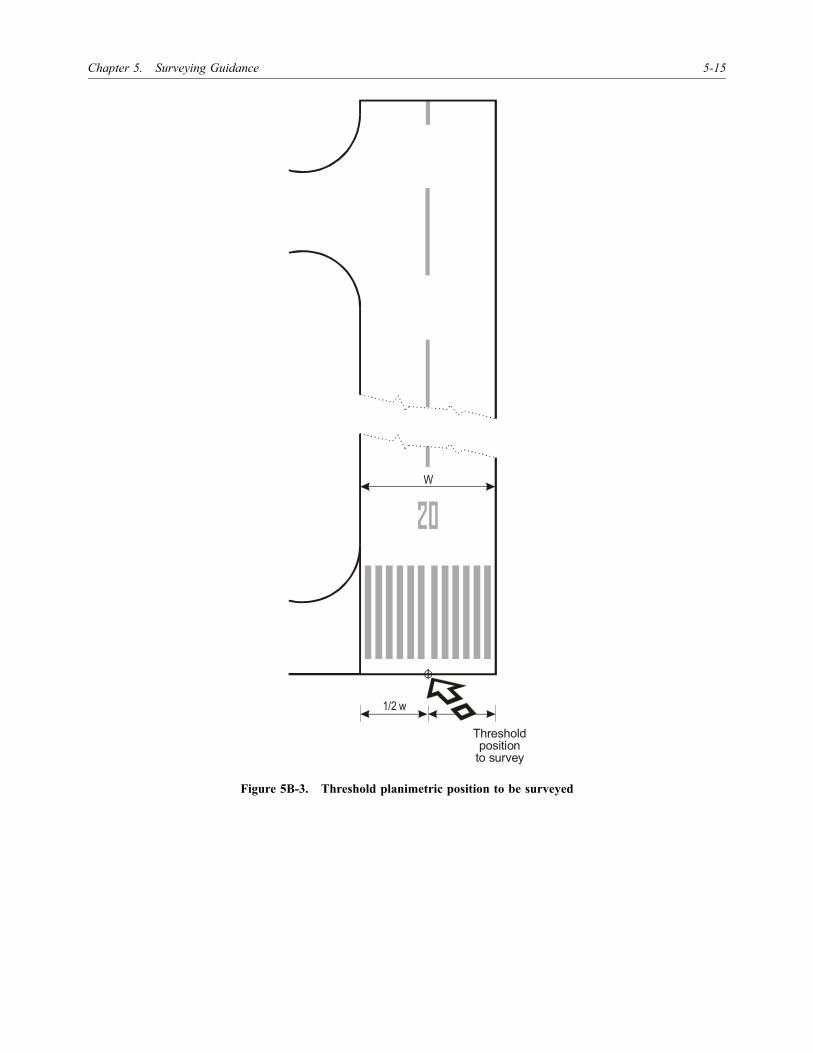
Chapter 5. Surveying Guidance 5-15
Figure 5B-3. Threshold planimetric position to be surveyed
1/2 w
W
Thresholdposition
to survey

5-16 World Geodetic System — 1984 (WGS-84) Manual
Figure 5B-4. TLOF and FATO planimetric threshold positions to be surveyed
H
1/2 w1/2 w
Touchdown and lift-off area (TLOF)
Final approach andtake-off area (FATO)
Positionto survey
Positionto survey
Positionto survey

Chapter 5. Surveying Guidance 5-17
Figure 5B-5. FATO planimetric threshold position to be surveyed
H
W
Thresholdposition
to survey
Thresholdposition
to survey
1/2 w
Final approach and take-off area (FATO)

5-18 World Geodetic System — 1984 (WGS-84) Manual
Figure 5B-6. ILS localizer
Figure 5B-7. MLS

Chapter 5. Surveying Guidance 5-19
Figure 5B-8. MLS
Figure 5B-9. VOR/DME

5-20 World Geodetic System — 1984 (WGS-84) Manual
Figure 5B-10. VOR
Figure 5B-11. DVOR/DME

Chapter 5. Surveying Guidance 5-21
Figure 5B-12. TACAN
. . .. .....

5-22 World Geodetic System — 1984 (WGS-84) Manual
Figure 5B-13. NDB

Chapter 5. Surveying Guidance 5-23
Figure 5B-14. Runway and taxiway intersections to be surveyed
r
r
r
+
+
r
+
r
r
B
A
CB
C
B
C
A
A Points of tangency of extended taxiway centre line
B Centre of radius (r)C Points of tangency of runway
centre lines

5-24 World Geodetic System — 1984 (WGS-84) Manual
Figure 5B-15. Runway and taxiway intersections to be surveyed
r
rr
r
+
+
Taxiway centre line marking(offset from runway centre line)
Runway centre linemarking
Taxiway centre line marking(offset from runway centre line)
Centre ofradius
Centre ofradius
Point of tangencyof arc with
centre line of runway
Point of tangencyof arc with extendedtaxiway centre line

Chapter 5. Surveying Guidance 5-25
Figure 5B-16. Runway holding positions to be surveyed
Intersection of extended taxiway centre linemarking and centre lineof barrier linemarking
PATTERN A
PATTERN B

5-26 World Geodetic System — 1984 (WGS-84) Manual
Figure 5B-17. Taxiway intersections to be surveyed
+
+
+
+
A
B
BB
B
CA
A
A
r
r
r
rr
r
rr
A Points of tangency of taxiway markingB Centre of radius (r)C Intersection of taxiway centre line
Intermediate holding positions
Intersection of extended taxiway centre line marking and centre line of intermediate holding position marking

Chapter 5. Surveying Guidance 5-27
Figure 5B-18. Helicopter air taxiway marker to be surveyed
Surveying point

5-28 World Geodetic System — 1984 (WGS-84) Manual
Figure 5B-19. Simple nosewheel lead-in line Figure 5B-20. Offset nosewheel lead-in line
Position Description of point to be surveyed
A Point of tangency of centre of lead-in marking with centre of taxilane markingB Centre of arc of lead-in line and radiusC Point of tangency with centre of lead-in line markingD Centre of arc of lead-in line and radiusE Point of tangency of centre of lead-in marking with centre of taxilane markingF Nosewheel position of parked aircraftG End of lead-in line marking
H Intersection of centre of lead-in line marking and centre of taxilane markingI Centre of arc of lead-in line and radiusJ Centre of commencement of straight section of lead-in lineK Intersection of centre of lead-in line marking and centre of taxilane markingL Centre of arc of lead-in line and radiusM Nosewheel position of parked aircraftN End of lead-in line marking
B C D
EA
r r
F
GStop line N
M
Stop line
Lead-in line
Lead-in line
+ r
r
J
LI
K H
+ +
+

Chapter 5. Surveying Guidance 5-29
Figure 5B-21 Figure 5B-22 Figure 5B-23
Simple nosewheel lead-out lines
Position Description of point to be surveyed
A Centre of commencement of turning line markingB Centre of arc of turning line and radiusC Centre of intersection of turning line marking and lead-out line markingD Centre of arc of lead-out line and radiusE Point of tangency of centre of lead-out line marking and taxilane markingF Centre of arc of lead-out line and radiusG Point of tangency of centre of lead-out line marking and taxilane marking
H Commencement of lead-out lineI Centre of commencement of curved section of lead-out lineJ Centre of arc of lead-out line and radiusK Point of tangency of centre of lead-out line marking and taxilane markingL Centre of arc of lead-out line and radiusM Point of tangency of centre of lead-out line marking and taxilane marking
N Point of tangency of centre of lead-out line marking and taxilane markingO Centre of commencement of curved section of lead-out lineP Centre of arc of lead-out line and radiusQ Point of tangency of centre of lead-out line marking and taxilane markingR Intersection of centre of lead-out line marking and taxilane marking
+ + +
NAB
D J P
O
FI
L
H
RQMKGE
CTurning lineLead-out line
+
+
+
r
r r r r r

5-30 World Geodetic System — 1984 (WGS-84) Manual
Figure 5B-24 Figure 5B-25 Figure 5B-26
Offset nosewheel lead-out lines
Position Description of point to be surveyed
A Centre of commencement of turning line markingB Centre of arc of turning line and radiusC Centre of intersection of turning line marking and lead-out line markingD Centre of end of straight section of lead-out line markingE Centre of arc of lead-out line and radiusF Intersection of centre of lead-out line marking and taxilane markingG Centre of arc of lead-out line and radiusH Intersection of centre of lead-out line marking and taxilane marking
I Commencement of lead-out lineJ Centre of commencement of curved section of lead-out lineK Centre of arc of lead-out line and radiusL Intersection of centre of lead-out line marking and taxilane markingM Centre of arc of lead-out line and radiusN Intersection of centre of lead-out line marking and taxilane marking
O Commencement of lead-out lineP Centre of commencement of curved section of lead-out lineQ Centre of arc of lead-out line and radiusR Intersection of centre of lead-out line marking and taxilane marking
++ +
+ AB
DJ P
OI
L RKGE
C
r
r r r r rF HM
N
Q
Turning lineLead-out line
Lead-out line
Lead-out line
+ +

Chapter 5. Surveying Guidance 5-31
Figure 5B-27. Turning lines
– – – – – – – – – – – –
Figure Position Description of point to be surveyed
5B-27 A Intersection of centre of lead-in line marking and centre of taxilane markingB Centre of arc of lead-in line and radiusC Centre of commencement of straight section of lead-in lineD Intersection of centre of lead-in line marking and centre of taxilane markingE Centre of arc of lead-in line and radiusF End of straight section of lead-in line marking/commencement of turning line markingG Centre of arc of turning line and radiusH Centre of commencement of straight section of turning line markingI Nosewheel position of parked aircraftJ Centre of end of straight section or turning line markingK True bearing of alignment barL Commencement of lead-out lineM Centre of commencement of curved section of lead-out lineN Centre of arc of lead-out line and radiusO Point of tangency of centre of lead-out line marking and taxilane markingP Centre of arc of lead-out line and radiusQ Point of tangency of centre of lead-out line marking and taxilane marking
N +
I
+P
H
QO
r r
F
+GL
K
M
C
D A
E+
r
r
J
r
Stop line
Turn bar
Alignment bar
Lead
-out
line
Lead
-in li
ne
Turning line
B +

5-32 World Geodetic System — 1984 (WGS-84) Manual
Attachment C. SURVEY REPORTS
1. GEODETIC CONNECTION
1.1 A survey report conforming to the followinggeneral format must be provided.
Contents list — Geodetic connection
1. Receipt note signed on behalf of the commissioningorganization indicating the date of receipt of thesurvey report, confirming its completeness andlisting the distribution of copies of the report.
2. Historical data (dates and general purpose of survey,names of surveyor and survey organization, etc.).
3. Description of the method of survey.
4. Details of the datum connection and the source ofthe control coordinates (i.e. original descriptions andcoordinate lists from the national geodetic organiz-ation or lists cross-referenced to previous surveys).
5. Control network diagram.
6. Survey station descriptions.
7. Schedule of points surveyed showing date of monu-mentation, description and survey.
8. Quality control report indicating equipmentcalibration information and the method of checkingof the survey. Demonstrable evidence that theaccuracy requirements have been met.
1.2 Records of actual observations must be provided ina separate indexed volume. Cross-references to observationsmust be made in the survey report.
2. AERODROME/HELIPORT SURVEY
2.1 A survey report conforming to the followinggeneral format must be provided.
Contents list — Aerodrome/heliport survey
1. Receipt note signed on behalf of the commissioningauthority indicating the date of receipt of the surveyand listing the distribution of copies of the report.
2. Historical data (dates and general purpose of survey,names of surveyor and survey organization, etc.).
3. Description of the method of survey.
4. Details of the observations made, cross-referencedto the control survey.
5. Navigation elements survey plan and cross-referenced witness diagrams (where necessary).
6. Schedule of points surveyed showing coordinatesand date of survey, including diagrams as required.
7. Quality control report indicating equipment cali-bration information and the method of checking ofthe survey. Demonstrable evidence that the accuracyrequirements have been met.
2.2 Records of actual observations must be provided ina separate indexed volume. Cross-references to observationsmust be made in the survey report.
3. EN-ROUTE SURVEY
3.1 A survey report conforming to the followinggeneral format must be provided.
Contents list — En-route survey
1. Receipt note signed on behalf of the commissioningauthority indicating the date of receipt of the surveyand listing the distribution of copies of the report.
2. Historical data (dates and general purpose of survey,names of surveyor and survey organization, etc.).
3. Description of the method of survey.
4. Details of the coordination of individual navigationaids.
5. Survey diagram showing the local surveyconnection by which the coordinates of the centreof the aid were obtained.
6. Schedule of points surveyed showing coordinatesand date of survey.

Chapter 5. Surveying Guidance 5-33
7. Quality control report indicating equipment cali-bration information and the method of checkingof the survey. Demonstrable evidence that theaccuracy requirements have been met.
3.2 Records of actual observations must beprovided in a separate indexed volume. Cross-referencesto observations must be made in the survey report.
– – – – – – – – – – – –

5-34 World Geodetic System — 1984 (WGS-84) Manual
Attachment D. COMPUTATION OF THRESHOLD COORDINATES
Where the centre line point actually surveyed does notcoincide with the threshold, the threshold coordinatesmay be derived by computation of coordinates of athreshold longitudinally offset from the point surveyedby using the following method:
(Angles in decimal degrees.)
Given: A (LatA, LonA) — runway centre line pointB (LatB, LonB) — surveyed threshold pointd (metres) — longitudinal offset to true threshold
Find: C (LatC, LonC)
PB = (LonB – LonA) × 1 852 × 60 × cos[(LatB + LatA)/2]PA = (LatB – LatA) × 1 852 × 60AB = +√(PB2 + PA2)k = d/AB
LatC = LatB + k(LatB – LatA)LonC = LonB + k(LonB – LonA)
Note 1.— Using the naming convention described, theabove formula works for all cases. The accuracy of theformula may be improved by using a more accurate localfigure than 1 852 m for 1 NM.
Note 2.— Longitudes west of Greenwich may be enteredas negative. Where the offset is from B towards A, thedimension d may be entered as negative.
Note 3.— These are approximate formulae and mayonly be used where d is small (i.e. less than 1 km and lessthan AB).
P
d
C (Lat , Lon )C C
B (Lat , Lon )B B
A (Lat , Lon )A A

6-1
Chapter 6
QUALITY ASSURANCE
6.1 QUALITY DEFINITIONS
6.1.1 It is essential to have a common understandingof the terminology used in discussing quality issues. Mostpeople will have different interpretations of the meaning of“quality” based on their personal experience. The followingdefinitions are included to establish consistency.
Procedures. The method used, i.e.: how the responsibilitiesfor the task should be assigned; what should beachieved in the tasks; and what should be recorded asthe associated quality record.
6.1.2 A procedure is not equipment-specific. It dealswith what should be achieved having satisfied the steps ofthe procedure. Work instructions are the detailed “how to”descriptions, for example, how to operate a particularinstrument or piece of equipment.
Quality. Totality of characteristics of an entity that bear onits ability to satisfy stated and implied needs (ISO8402*).
Note.— Entity is an item that can be individuallydescribed and considered (ISO 8402*).
6.1.3 In this case, it indicates the ability of a product toconsistently meet its stated requirements, i.e. it is qualifiedfor its specified purpose. There is no single or absolutemeasure of quality although statements about the quality ofa process or item may be based upon physical measurementsand observations, for example, quality level.
Quality assurance (QA). All the planned and systematicactivities implemented within the quality system, anddemonstrated as needed, to provide adequate confid-ence that an entity will fulfil requirements for quality(ISO 8402*).
6.1.4 In other words, QA is the process of ensuringthat stated quality specifications are incorporated in thefinal product, by use of pre-defined methods. Once a
method has been proven to produce the required productsuccessfully, a system is required that can assure that themethod or methods are followed correctly each time theprocess is repeated. All activities and functions that affectthe level of quality of a product are of concern to QA whichis achieved through the use of a quality system.
Quality control. The operational techniques and activities thatare used to fulfil requirements for quality (ISO 8402*).
Quality level. The extent to which the customer’s needshave been met. A quality level of 100% means thatthere has been a complete conformance to specificationevery time.
Quality management. All activities of the overall manage-ment function that determine the quality policy,objectives and responsibilities, and implementing themby means such as quality planning, quality control,quality assurance and quality improvement within thequality system (ISO 8402*).
6.1.5 This could be interpreted as the implementationof QA.
Quality record. Documented evidence of tasks carried outwhich demonstrates that the required results have beenachieved and provides sufficient links to other qualityrecords to ensure traceability.
Quality specifications. The minimum, pre-defined specifi-cations that must be met to fulfill the stated qualityrequirements. A quality system provides the managementcontrol to assure the required quality specifications areachieved.
Quality system. The organizational structure, procedures,processes and resources needed to implement qualitymanagement (ISO 8402*).
* ISO Standard 8402 — Quality Management and QualityAssurance —Vocabulary, Second Edition

6-2 World Geodetic System — 1984 (WGS-84) Manual
Requirements for quality. Expression of the needs or theirtranslation into a set of quantitatively or qualitativelystated requirements for the characteristics of an entity toenable its realization and examination (ISO 8402*).
Resolution. A number of units or digits to which ameasured or calculated value is expressed and used.
Traceability. Ability to trace the history, application orlocation of an entity by means of recorded identifi-cations (ISO 8402*).
Validation. Confirmation by examination and provision ofobjective evidence that the particular requirements for aspecific intended use are fulfilled (ISO 8402*).
Verification. Confirmation by examination and provision ofobjective evidence that specified requirements havebeen fulfilled (ISO 8402*).
Note.— Objective evidence is information which can beproved true, based on facts obtained through observation,measurement, test or other means (ISO 8402*).
Work instructions. Actual steps to carry out a procedure.These are the details that are specific, for example, to aparticular piece of equipment used in the productionprocess.
6.2 QUALITY ASSURANCE (QA)
6.2.1 Need for a quality assurance system
The objective of WGS-84 implementation is to producecoordinate data referenced to a common datum in which ahigh degree of confidence can be placed in the accuracyand integrity of the data. The method used to acquire all thepositional data to the required standard has to address theproblems of the size of the task. All the coordinatesproduced should be traceable back to their origin along anunbroken trail. Each point is unique so that quality controlchecks on a sample would not be suitable. Considering thelarge number of points and the geographical spread, itwould be impractical to independently check every singlepoint. However, it is possible to check the method by whichthe data are acquired. This can be achieved by QA.
6.2.2 Quality assurance and WGS-84implementation
6.2.2.1 QA is about preventing errors, rather thanfixing them. To do this, it is essential to understand the
requirement. The various tasks involved need to beidentified and managed efficiently. This is done by using aquality system or quality management system (QMS). Thebasic elements of such a system could be (see Figure 6-1):
a) Organization (the management structure). It is veryimportant that the responsibilities for the operationare stated and understood by all concerned, i.e.everyone knows who does what.
b) Planning/procedures. Identifying the tasks to bedone and developing procedures necessary for theproduction process.
c) Documentation. Procedures should be written downto enable consistency of application by differentpersonnel. Documents can be updated, but under anauthorized control procedure. Written quality recordsare needed to provide traceability if there is aproblem to be located.
d) Assessment. The most important part of any qualitysystem is the method of assessment used, i.e. the auditprocess. It provides the checks that show whether theprocedures are being used correctly and whether theyare achieving the required results. It initiates the loopto make improvements where necessary. The aim ofan assessment is to provide constructive recommen-dations for improvement where there are non-conformances and to establish confidence in themethods where there is conformance.
e) Review. The process of considering the assessmentresult and implementing any necessary changesthrough a corrective action procedure.
Note.— The International Organization for Standard-ization (ISO) 9000 series of quality assurance standardsprovides a basic framework for the development of aquality assurance programme. The details of a successfulprogramme are to be formulated by each State and in mostcases are unique to each State’s organization.
6.2.2.2 Figure 6-2 is an example of a QMS structureapplicable to the QA of the acquisition of new data. Itillustrates:
a) the objectives and responsibilities as set up withinthe national administration;
b) various planning tasks, including:
i) decision to use existing data or to resurvey;
ii) type of survey: geodetic, aerodrome or en-route;
Chapter 6. Quality Assurance 6-3
iii) accuracy requirements; and
iv) briefing of survey contractors on the accuracyrequirements and safety issues, and evaluatingtheir suitability before awarding contracts;
c) two outcomes from the assessment process (audit):
i) conformance, in which case, the data can thenbe processed; and
ii) non-conformance, where the process flow shouldthen loop back to the planning stage via acorrective (remedial) action procedure.
6.2.3 Safety aspects in surveying
6.2.3.1 A quality system must take into account safetyaspects in surveying. Involvement in safety has various legalpositions to be considered and will vary within each adminis-tration. A quality system, however, needs to encourage safeworking practices as any accident is a reflection on the qualityof the service, for example, making sure that the survey teamsare well briefed on the type of survey they have to do and areaware of any local procedures. This is particularly importantwhere work at aerodromes is concerned.
6.2.3.2 Prior to awarding any contracts, evaluation ofthe survey company’s experience should be considered, i.e.how many aerodrome surveys they have conducted. Tofollow the requirements of a QMS, quality records shouldbe kept, such as a checklist of the briefing of the surveyteam. If there is no acknowledgment that the survey teamhas been briefed on the aerodrome safety requirements,then the team should not proceed.
6.2.4 Quality plans
The QMS described above has been designed purely for theQA of the origin of WGS-84 data, largely relying on theacquisition by survey teams. The scope of this system doesnot include the management of all the navigation dataprocesses that may be the responsibility of an AISdepartment. It is possible, however, for this QMS tofunction as a subsidiary element within a total qualitysystem having a wider scope. The subsidiary QMS isreferred to as a quality plan. For example, the QMSdescribed in Figure 6-2 has been labelled the State qualityplan. This plan can be incorporated within an existingadministration’s quality system or as part of a new onealong with other quality plans, such as one for managing theonward flow of data via database storage and publication.Figure 6-3 gives an example of such a total datamanagement system.
6.2.5 Information neededto define data quality
If integrity is to be assured and demonstrable, allcoordinates must be traceable to their source by anunbroken trail. While the Cyclic Redundancy Check (CRC)will be used by receivers of data to confirm correct receipt,it is not sufficient to define the quality of the data.Therefore, a record must be kept of all changes made. Thefollowing are some of the elements of a sample set of therequired data record:
a) data accuracy;
b) data origin;
c) details of changes made to the data;
d) reason for the data change;
e) references associated with the data change;
f) the source of the data change;
g) the identity of the person making the change;
h) date of the change.
6.2.6 Procedures to ensure traceability
6.2.6.1 The quality records must be kept by theorganization carrying out the data modification. While anindicator allowing the retrieval of this information willneed to be associated to data transferred to the nextintended user, together with the CRC, the quality recorditself does not need to be sent.
6.2.6.2 The quality records may be in electronic or hardcopy format. To provide for the unbroken trail, certainchange information must remain with the data item through-out the data manipulation and use and must, whereverpossible, be stored in an associated field or record.
6.2.7 Procedures to ensure integrity
6.2.7.1 The accuracy of data (see Chapter 2) isdetermined at the point where the data originate. In the case ofsurveyed data, procedures necessary to ensure the establishedaccuracy can be found in Chapter 5 — Surveying Guidance.Procedures for calculating points must not only take intoaccount the accuracy of the known (surveyed) data, but mustalso ensure that subsequent mathematical manipulation

6-4 World Geodetic System — 1984 (WGS-84) Manual
maintains the accuracy requirements set by the data model.Declared points must be declared to the accuracy required bythe data model provided in Chapter 2.
6.2.7.2 If data integrity is to be assured, there must beclearly defined procedures for all stages of the navigationdata process, from the point where the data are originatedto the point where the data are used. Apart from rigorousmanual independent verification, there is little that can bedone to ensure the integrity of data held in a manualsystem. However, once the data are held on electronicmedia, there are a number of options available. Whenchoosing appropriate methods to protect the integrity ofelectronically stored data, consideration must be given tothe integrity requirements for the data and the risk posed tothat data.
6.2.8 Manual data entry
The transfer of data from written or printed form into anelectronic format is the greatest potential source of error inthe entire process. Careful consideration must be given tothe means by which this transfer is to be performed andverified if end-to-end data integrity at the required levels isto be achieved.
6.2.9 Data validation checks
Data validation checks, which can be performed once thedata item is held in electronic format, will detect many ofthe errors induced by manual data entry, but it is doubtfulwhether integrity can be improved even by one order ofmagnitude on the basis of validation checks alone.
6.2.10 Software aspects
6.2.10.1 Whenever data are manipulated by a computerprogramme, even if it is simply to extract an item from thedatabase and output it onto magnetic media, there is a riskthat, as a result of software error, the resultant data item willnot be a true copy of the original. Accordingly, all softwareused to manipulate data must be subject to rigorous testing,verification and validation.
6.2.10.2 In addition to the threat to data integrityposed by a software fault, there is a threat from computerviruses which may be introduced via an executable code inapplications software and utilities. This aspect must also beaddressed by the configuration management system.
6.2.11 Data retention aspects
Although hardware reliability has improved markedly overthe years, there is still a risk of corruption from componentfailure or power surge/spike. Detection of corruptioncaused by hardware faults can be improved by the use ofvalidation and verification checks at regular intervals.
6.2.12 Data transfer aspects
The risk to data, while being written to or read frommagnetic/optical storage media, depends on the devicesused and the methods employed in the packing and handlingof the media. Protection is provided by the softwarecontrolling the reading from/writing to the media. Toachieve the protection of data while stored or beingtransferred, the CRC must be used. (See Chapter 7 fordetails.)

Chapter 6. Quality Assurance 6-5
FIGURES FOR CHAPTER 6
Figure 6-1. Basic structure of a quality system (QA loop)
Figure 6-2. Model of a State quality plan
Review/corrective action
Productionprocess
Planning
Organization
Policy/objectives
Audit/assessment
Feedback
Report
PlanningRemedial
action
Review ofexisting data
Resurvey
Assessment
Data to AIS
ObjectivesResponsibilities
Unsatisfactory
Conformance

6-6 World Geodetic System — 1984 (WGS-84) Manual
Figure 6-3. Quality plans within a quality system
Data qualitymanagement system
Statequality plan
(for dataacquisition) Maintenance
Format and
security
Storage/publication/
transfer
Externaldata
Data transfer to users’various media
Data producedoutside the system
Systemboundary
Queries

7-1
Chapter 7
DELIVERABLES
7.1 SURVEY REPORTINGREQUIREMENTS
7.1.1 It is important to know what type of data hasbeen surveyed and to what level of accuracy and resolutionthis was done. The classification of data types, accuracy andresolution was described in Chapter 2. In addition to theproduction of accurate positional data, the other aim ofWGS-84 implementation is to be able to recall the historyof that data. It is the survey report that will provide thedetails of the acquisition method used. This is the qualityrecord that will be used for assessment and future reference.
7.1.2 It is therefore essential that the surveyors recordall the necessary information. In this way, all survey workundertaken to determine the coordinates of navigationfacilities can be reported in a predefined format. Where anexisting national reporting practice differs from that shownin this manual, national administrations may make a case insupport of the national practice, where this can be shown tobe compatible.
7.1.3 An advantage to having consistency in thereport through the use of standardized formats could berealized in the assessment (audit) phase. Checklists wouldfacilitate an efficient audit process particularly where largenumbers of surveys are involved. Further advantages ofchecklists are their use in briefing the survey teams on therequirements of the surveying standards and as a guidancedocument for the reporting requirement, the benefit beingconsistency for the administration.
7.2 BASIC REPORTINGSTRUCTURE
7.2.1 The following is an example of the basicreporting format structure:
a) Three types of reporting formats.
i) Geodetic survey,
ii) En-route survey,
iii) Aerodrome/heliport survey.
There is also the case of coordinate data that have beenproduced by conversion from an existing data set, whichitself should have originated from one of the above surveytypes.
b) Common reporting elements. A number of topicsare common to each of the report formats.
i) Historical data should describe the generalsurvey information as follows:
— the purpose,
— the date, and
— the surveyors’ names and the company.
ii) Survey method used: This is the actual way thesurvey was carried out, not just a description ofthe theory behind the technique used.
iii) Diagrams: Where relevant, diagrams should beincluded, i.e. for station descriptions, controlnetworks and threshold descriptions.
iv) The quality control report should provideinformation on the equipment calibrationscarried out. It should also describe the methodsused to check the survey and, in particular,show evidence that the required accuracy forthe particular data type has been achieved.
v) Observations: Records of the actual observ-ations should be provided in a separate volume.Cross-references should be made to the surveyreport.
c) Aerodrome/heliport survey report format. Thefollowing lists a complete reporting format for anaerodrome/heliport survey.

7-2 World Geodetic System — 1984 (WGS-84) Manual
1. A receipt note signed on behalf of thecommissioning authority, indicating the date ofreceipt of the survey and the number of copiesof the report.
2. Historical data giving the dates and purpose ofthe survey, the survey company names andpersonnel.
3. Description of the method of the survey.
4. Details of the observations made with cross-references to the control survey.
5. A facility survey plan with cross-referencedwitness diagrams (where necessary).
6. Schedule of the points surveyed giving thecoordinates and the date when surveyed.
7. QC report giving equipment calibration detailsand describing the methods used to check thesurvey. In addition, evidence should be providedto show that the accuracy requirements havebeen met.
8. Actual observations (provided in a separatevolume), indexed so that cross-references canbe included in the report.
7.3 FORMATS, STANDARDALGORITHMS AND
WORKING PRACTICES
The following data format, standard algorithms andworking practices are suggested for common use.
7.3.1 Universal Data Delivery Format (UDDF)
7.3.1.1 The Universal Data Delivery Format (UDDF),submitted by the United States (Federal Aviation Adminis-ration document No. 405, Standards for Aeronautical Dataand Related Products), is a digital delivery system whichprovides aeronautical and other data, including aerodrome/heliport, runway, navigation aid and obstacle, in a standardASCII format. This information can be easily read into theuser data files and databases. It details the format to be usedwhen reporting surveyed data to the AIS.
7.3.1.2 Inquiries, comments or recommendationsconcerning UDDF are encouraged and should be addressedto:
Robert FisherManager, FAA ProgramsPhotogrammetry Branch, NGSD1315 East-West HighwaySilver Spring, Maryland 20910
7.3.1.3 FAA document No. 405 is organized asfollows:
a) Structure overview describes the general structureof the UDDF format.
b) Conventions describes UDDF conventions, such asthe use of record type separators and fielddelimiters.
c) Annotated file listing presents annotated UDDFfiles which include code numbers at the beginningof each field. The code numbers have been decodedindicating data description, field type and fieldcolumns.
7.3.1.3.1 Structure overview. The UDDF is imple-mented in seven files, each file providing data for one ofseven survey types, as follows:
a) airport obstruction chart (AOC);
b) area navigation approach precision conventionallanding (APC)
c) area navigation approach non-precision conventionallanding (ANC);
d) area navigation approach precision vertical landing(APV);
e) area navigation approach non-precision verticallanding (ANV);
f) engine out departure (EOD);
g) special purpose (SPL).
7.3.1.3.1.1 Each of these files is organized into thefollowing data sections.
a) Airport data furnishes airport name, ICAO locationindicator, FAA site number, survey date, surveyedition, magnetic declination and other airport andsurvey information.

Chapter 7. Deliverables 7-3
b) Runway data furnishes thresholds and displacedthresholds, stopway, blast pad and other runway-related information.
c) Navigation aid data furnishes navigation aidinformation including computed distances betweennavaids and selected runway points.
d) Obstacle data furnishes information on obstacles,including computed distances from and heightsabove selected runway points.
e) Special notices lists miscellaneous information thatcannot be logically included with the other data,such as advisories of possible surface penetrationsby vessels.
7.3.1.3.2 Conventions. UDDF information is furnishedas ASCII files. The file name identifies the airport,approximate survey date and survey type. Each field isdelimited by the vertical broken line symbol and datasections are separated within the file by the “@” symbol.Data sections within a section, such as data for individualrunways within the runway section, are separated by the “#”symbol. The end of the file is indicated by “EOF”.
7.3.1.3.3 Annotated file listing. An annotated file withfield descriptions is required (see Figure 7-1).
7.3.1.3.4 When entering data into the database, it willbe necessary to:
a) confirm the data against the original survey data;
b) enter the data under strict quality control procedures;and
c) verify entered data.
7.3.2 Cyclic redundancy check (CRC) algorithm
7.3.2.1 For those civil aviation authorities who will bedeveloping the electronic aeronautical database, it is specifiedthat the transfer of data, whether from personal computer topersonal computer, within a database, or digitally overcommunication networks, be monitored by a cyclicredundancy check (CRC) determined for the batch of data tobe transferred. A CRC can also be used to monitor theintegrity of specific records within the database. Dataintegrity values to be maintained for specific data within adatabase or while being transferred are grouped in Tables 2-1to 2-5.
7.3.2.2 CRC is an error detection algorithm capable ofdetecting small changes in a block of data. For those civil
aviation authorities who will continue to develop andtransfer data using manual processes, a CRC value could beattached to the data set so that each succeeding user whoreceives the data could compare the original CRC to arecalculated value. A hard copy Aeronautical InformationPublication (AIP) could be created using a desktoppublishing system that would provide the aeronautical datain an electronic format. Individual data or all the datacontained in one page could then be “wrapped” into theCRC to ensure the protection of data. The resultingcalculated value of the CRC applied should be printedeither together with the specific individual data or for thewhole page. In this way, the CRC value attached to theoriginal data values could be monitored from data creationthrough publication. Recipients of data, such as the datapreparation agency and the avionics manufacturer, wouldthen be able to verify the integrity of the values receivedfrom the civil aviation authority prior to inputting into thedatabase by comparing the printed CRC value with thevalue obtained from their own, independent CRC check.
7.3.2.3 CRC is a mathematical process whereby asequence of N data bits is manipulated by an algorithm toproduce a block of n-bits, known as the CRC, where n isless than N. A check of the integrity of the data can beperformed by comparing the result of the application of theCRC algorithm with the declared expected result. A failureof the mathematical routine to regenerate the CRC valuefrom the data indicates that either the data or the CRC hasbecome corrupt and the data are, therefore, no longerreliable. By careful choice of the algorithm employed, inconjunction with the relative values of n and N, it can beguaranteed that more than a specified proportion of theoriginal N-bits must be corrupted before there is anypossibility of the same resultant n-bit code being produced.For a given CRC formula, the ratio between n and N willdetermine the integrity level achieved for any data element.
7.3.2.4 In summary, the characteristics of a CRC are:
a) it is better than check sums or parity bits for errordetection;
b) the elements of generating a CRC are
— a data block divided by a generating polynomial,
— the CRC is resulting remainder,
— the CRC is tagged onto the end of the datablock, and
— no errors gives the remainder from division aszero;

7-4 World Geodetic System — 1984 (WGS-84) Manual
c) the assurance of error detection (see relationshipbetween data integrity and CRC length as containedin Table 7-1).
7.3.2.5 Standard CRC algorithms
7.3.2.5.1 The generator polynomial of a CRCalgorithm is measured in bit size where the polynomialcoefficients are binary values equal to 0 or 1. The level ofintegrity protection provided by a specific generatorpolynomial is a function of the highest order term in thepolynomial. The higher the term, the higher the level ofprotection. From the following generator polynomials:
a) 1 + x5 + x12 + x16 is the CRC-CCITT algorithm;and
b) 1 + x + x3 + x5 + x7 + x8 + x14 + x16 + x22 + x24 +x31 + x32 is the CRC-32Q algorithm.
7.3.2.5.2 The CRC-CCITT algorithm is a 16-bitalgorithm and provides less protection than the CRC-32Qalgorithm, which is a 32-bit algorithm. The above CRCalgorithms are suggested for uniform application by Statesworldwide.
7.3.2.6 Using a CRC for checking7.3.2.6 the correctness of data
7.3.2.6.1 Integrity cannot be added once it is lost.Thus, the integrity assurance must be provided fromorigination to final application. It is therefore suggestedthat when a data item is entered into an electronic format,it will need to be provided with the CRC, thereby providingthe capability for verification on its transfer to the nextintended user. Then, and at each subsequent step, thereceiver must confirm the data validity to provide assurancethat data have not been corrupted while stored or duringtransmission.
7.3.2.6.2 The insertion of data into the database at thestart of the process is therefore a most critical point in thewhole process. At this time it will be necessary to:
a) confirm the correctness against the original surveydata;
b) enter data under strict quality control procedures;and
c) execute checks to verify data following entry.
7.3.2.6.3 For the CRC to be used for checking thecorrectness of data, the chosen CRC must meet the level ofintegrity required for the individual data items to betransferred. This CRC value will need to be associated withthe smallest related set of data. Thus, for much of theWGS-84-related subject of implementation, this smallestelement will be a single point. A suitable set of data for aCRC check could also be a procedure and, ultimately, awhole aeronautical database.
7.3.2.7 Different computer formats and7.3.2.7 their effect on CRC
Ideally, once formed, the CRC would remain unchangeduntil its application in the flight management system (FMS)or RNAV system. However, data formats change during theprocess and a CRC is only valid for a particular dataformat. For example, data are held in a computer in aformat dependent upon word length which is unlikely to bethe same in the database of the supplier or the RNAV/FMS.Thus, it will be necessary to recalculate the CRC at varioussteps in the management of data. This recalculation must becarried out under strict quality control if the CRC is toremain a valid indication of integrity.
7.3.2.8 Integrity and CRC length
7.3.2.8.1 CRC offers absolute assurance of errordetection when there is only a single period of “burst error”within the stream of data that was subjected to the CRC,provided that the substring containing all affected bits isshorter than the length of the CRC employed. If theseparation of corrupted bits is greater than the length of theCRC, the probability of an undetected error is theprobability that the same CRC will be produced from both
Table 7-1. Integrity and CRC length
Lengths of CRC
Integrity Bits Characters
3.9 × 10⁻³ 8 1
1.5 × 10⁻⁵ 16 2
6.0 × 10⁻⁸ 24 32.3 × 10⁻¹⁰ 32 4

Chapter 7. Deliverables 7-5
the original and the corrupted data. Assuming an “even”mapping of valid data strings to the CRC, the probability ofan undetected error rises to a maximum of 2-n when thenumber of bits protected by the CRC is several times thelength of the CRC itself.
7.3.2.8.2 Table 7-1 gives the length of the CRCrequired to achieve different levels of assurance ofdetection of multiple bit error in the data, where there is noguarantee that the separation of the bits in error is less thanthe length of the CRC. In order to achieve an integrityassurance of 1 × 10⁻⁸, it is therefore necessary to employ a32-bit CRC.
7.3.2.9 Example of CRC generation
7.3.2.9.1 The algorithm by which a CRC is producedis defined by a generating polynomial (GP). The GP for ann-bit CRC is of order n; the coefficients are either 0 or 1,with the constraints that the polynomial is primitive andthat the coefficients of x0 and of xn are both 1. To generatea CRC, a data block is divided by a GP. The resultingremainder, the CRC, is usually tagged onto the end of thedata block. When the data are subsequently checked, anidentical division is performed on the data although theremainder is now included. If no errors have occurred, theremainder from this division should be 0.
7.3.2.9.2 This can be shown with the followingmathematics, carried out using modulus 2 arithmetic.
Let:
D = data, GP = generator polynomial, Q = quotient andR = remainder.
(Suffixes O and R denote Transmitter and Receiver,respectively.)
Then:
D = QO × GP + RO (at origination)
D + RO = QR × GP + RR (at receiver)
which can be represented as D = QR × GP + RR + RO.
It follows that:
QO × GP × RO = QR × GP + RR + RO.
Cancel GP and RO to give:
QO = QR if RR = 0 (i.e. no errors).
7.3.2.9.3 A CRC can be implemented with simpleshift registers and exclusive OR (XOR) gates. For clarity,the following example is performed manually.
7.3.2.9.4 CRC generation.
7.3.2.9.4.1 An example of the generation of a CRC isshown at Figure 7-2. The data is 11011001, the GP is 11001and the CRC is 4 bits long.
7.3.2.9.4.2 One of the prerequisites for the GP is thatit is 1 bit longer than the CRC.
7.3.2.9.4.3 Four zeros are appended to the data (thelength of the CRC) and the data (with the four zeros added)are XORed with the GP. This operation yields a quotientand a remainder (the CRC).
7.3.2.9.5 Validation. The CRC is now appended to thedata. When the receiver of the data passes this stringthrough the same calculation again, there will be a zeroremainder if no errors have occurred (see Figure 7-3).

7-6 World Geodetic System — 1984 (WGS-84) Manual
FIGURES FOR CHAPTER 7
Figure 7-1. UDDF format for navigation aid data
Figure 7-2. Data divided by GP to generate the CRC
0 1 2 3 4 5 6 712345678901234567890123456789012345678901234567890123456789012345678901...|ASR (MFR) | 422306.6000| –1225146.7000| 1310.0| | | |60 61 62 63 64 65 66
|DME (14) | 422140.0470| –1225201.8010| 1334.0| | | ||GS (14) | 422242.4910| –1225224.7530| 1297.1| | | ||GS (14) PP | 422241.0590| –1225229.7230| 1299.7| | 400| 1081||LOC (14) | 422140.1380| –1225157.8070| 1318.9| | 998| ||LMM (14) | 422321.0000| –1225250.6000| | | 3250| ||LOM (14) | 422703.2000| –1225448.2000| | | 27420| ||VORTAC (OED) | 422846.5000| –1225446.7000| 2080.0| | | |
Items 1 to 6 are UDDF field descriptions with the following meaning:
1. AIRPORT IDENTIFIER/A6/2-72. AIRPORT SITE NUMBER/A10/9-183. FAA REGION/A4/20-234. SURVEY TYPE/A6/25-30
AOC — AIRPORT OBSTRUCTION CHART SURVEYEOD — ENGINE OUT DEPARTURE SURVEYNPA — NON-PRECISION AREA NAVIGATION APPROACH SURVEY PAA — PRECISION AREA NAVIGATION APPROACH SURVEYSPL — SPECIAL PURPOSE
5. OC NUMBER/I5/32-366. OC EDITION/A3/38-40
1 0 0 1 1 1 1 1 QUOTIENT
1 1 0 0 1 1 1 0 1 1 0 0 1 0 0 0 0
X O R 1 1 0 0 1
0 0 0 1 0 0 0 1
1 1 0 0 1
0 1 0 0 0 0
1 1 0 0 1
0 1 0 0 1 0
1 1 0 0 1
0 1 0 1 1 0
1 1 0 0 1
0 1 1 1 1 0
1 1 0 0 1
0 0 1 1 1Remainder (CRC)
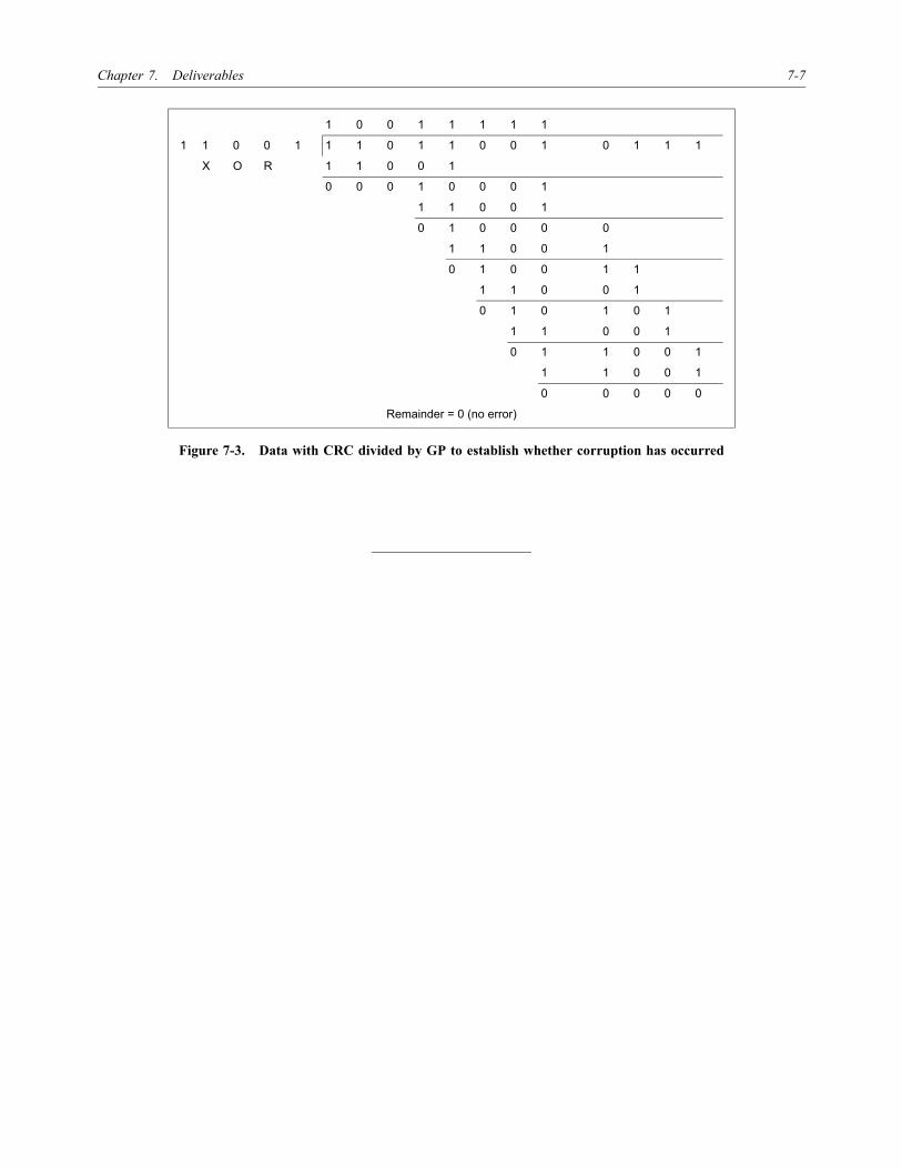
Chapter 7. Deliverables 7-7
Figure 7-3. Data with CRC divided by GP to establish whether corruption has occurred
1 0 0 1 1 1 1 1
1 1 0 0 1 1 1 0 1 1 0 0 1 0 1 1 1
X O R 1 1 0 0 1
0 0 0 1 0 0 0 1
1 1 0 0 1
0 1 0 0 0 0
1 1 0 0 1
0 1 0 0 1 1
1 1 0 0 1
0 1 0 1 0 1
1 1 0 0 1
0 1 1 0 0 1
1 1 0 0 1
0 0 0 0 0
Remainder = 0 (no error)

�������

A-1
Appendix A
THE GLOBAL POSITIONING SYSTEM (GPS)
1. BASIC CONCEPT
The Navigation System with Time And Ranging(NAVSTAR) Global Positioning System (GPS) is an all-weather, space-based navigation system, which has beendesigned primarily for the United States Department ofDefense. In use since 1973, it became fully operational in1994, allowing the worldwide and instantaneous deter-mination of a vehicle’s position and velocity (i.e.navigation) as well as the precise coordination of time.
2. SYSTEM ORGANIZATION
The Global Positioning System is made up of three majorsegments:
a) The Control Segment with ground-based equipmentfor monitoring the satellites and updating theinformation they transmit. As its name suggests, theOperational Control System (OCS) maintains andsupports the rest of the system. It has three mainactivities — tracking, prediction, and uploading —and consists of a single Master Control Station(MCS), five monitor stations, and three groundantennas.
b) The Space Segment providing global coverage withfour to eight simultaneously observable satellitesabove 15° elevation. This is accomplished byhaving satellites in six nearly circular orbits with analtitude of about 20 200 km above the earth over aperiod of approximately 12 hours. The number ofoperational satellites is 21 (plus three additionalactive spares), with an inclination of 55° and withfour satellites per plane. The spare satellites areused to replace a malfunctioning “active” satellite.
c) The User Segment, comprising an unlimited numberof receivers, which receive the satellite signals andcalculate instantaneous position and othernavigation information.
3. GPS SATELLITESIGNAL STRUCTURE
3.1 The actual carrier broadcast by the satellite is aspread spectrum signal that makes it less subject to inten-tional (or unintentional) jamming. The spread spectrumtechnique is commonly used today by such diverse equip-ment as hydrographic positioning ranging systems andwireless Local Area Network (LAN) systems.
3.2 The key to the system’s accuracy is the fact thatall signal components are precisely controlled by atomicclocks. The Block II satellites have four on-board timestandards: two rubidium and two caesium clocks. Thesehighly accurate frequency standards, being the heart of GPSsatellites, produce the fundamental L-band frequency of10.23 MHz. Coherently derived from this fundamentalfrequency are two signals, the L1 and the L2 carrier waves,generated by multiplying the fundamental frequency by154 and 120, respectively, thus yielding:
L1 = 1 575.42 MHz (19 cm), and
L2 = 1 227.60 MHz (24 cm).
3.3 These dual frequencies are essential for theelimination of the major source of error, i.e. ionosphericrefraction. The pseudo-ranges that are derived from themeasured travel time of the signal from each satellite to thereceiver use two pseudo-random noise (PRN) codes that aremodulated (superimposed) onto the two-base carrier waves.The first code is the C/A code (Coarse/Acquisition code),also designated as the Standard Positioning Service (SPS),which is available for civilian use. The C/A code, with aneffective wavelength of 293.1 m, is modulated only on L1and is purposely omitted from L2.
3.4 The second code is the P code (Precision code),also designated as the Precise Positioning Service (PPS),which has been reserved for use by the U.S. military andother authorized users. The P code, with an effectivewavelength of 29.31 m, is modulated on both carriers L1and L2.
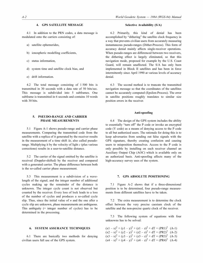
A-2 World Geodetic System — 1984 (WGS-84) Manual
4. GPS SATELLITE MESSAGE
4.1 In addition to the PRN codes, a data message ismodulated onto the carriers consisting of:
a) satellite ephemerides,
b) ionospheric modelling coefficients,
c) status information,
d) system time and satellite clock bias, and
e) drift information.
4.2 The total message consisting of 1 500 bits istransmitted in 30 seconds with a data rate of 50 bits/sec.This message is subdivided into 5 subframes. Onesubframe is transmitted in 6 seconds and contains 10 wordswith 30 bits.
5. PSEUDO-RANGE AND CARRIERPHASE MEASUREMENTS
5.1 Figure A-1 shows pseudo-range and carrier phasemeasurements. Comparing the transmitted code from thesatellite with a replica of it generated by the receiver resultsin the measurement of a time shift Δt, also called pseudo-range. Multiplying it by the velocity of light c (plus variouscorrections) results in a user-to-satellite distance.
5.2 The carrier of the signal emitted by the satellite isreceived (Doppler-shifted) by the receiver and comparedwith a generated carrier. The phase difference between bothis the so-called carrier phase measurement.
5.3 This measurement is a subdivision of a wave-length of the signal, and the integer number of additionalcycles making up the remainder of the distance isunknown. The integer cycle count is not observed butcounted by the receiver. Every loss of lock leads to a lossof the number of cycles and produces a so-called cycleslip. Thus, since the initial value of n and the one after acycle slip are unknown, phase measurements are ambiguous.This ambiguity (= integer number of cycles) has to bedetermined in the processing.
6. SYSTEM ASSURANCE TECHNIQUES
6.1 There are basically two methods for denyingcivilian users full use of the GPS system.
Selective Availability (S/A)
6.2 Primarily, this kind of denial has beenaccomplished by “dithering” the satellite clock frequency ina way that prevents civilian users from accurately measuringinstantaneous pseudo-ranges (Dither-Process). This form ofaccuracy denial mainly affects single-receiver operations.When pseudo-ranges are differenced between two receivers,the dithering effect is largely eliminated, so that thisnavigation mode, proposed for example by the U.S. CoastGuard, will remain unaffected. The S/A has only beenimplemented in Block II satellites and has been in forceintermittently since April 1990 at various levels of accuracydenial.
6.3 The second method is to truncate the transmittednavigation message so that the coordinates of the satellitescannot be accurately computed (Epsilon-Process). The errorin satellite positions roughly translates to similar sizeposition errors in the receiver.
Anti-spoofing
6.4 The design of the GPS system includes the abilityto essentially “turn off” the P code or invoke an encryptedcode (Y code) as a means of denying access to the P codeto all but authorized users. The rationale for doing this is tokeep adversaries from sending out false signals with theGPS signature, thereby creating confusion and causingusers to misposition themselves. Access to the P code isonly possible by installing on each receiver channel anAuxiliary Output Chip (AOC) which is available only onan authorized basis. Anti-spoofing affects many of thehigh-accuracy survey uses of the system.
7. GPS ABSOLUTE POSITIONING
7.1 Figure A-2 shows that if a three-dimensionalposition is to be determined, four pseudo-range measure-ments from different satellites have to be taken.
7.2 The extra measurement is to determine the clockoffset between the very precise caesium clock of thesatellite and the non-precise quartz clock of the receiver.
7.3 The following system of equations with fourunknowns has to be solved:
(x1 – x)2 + (y1 – y)2 + (z1 – z)2 + dT = (PR1)2 (A-1)(x2 – x)2 + (y2 – y)2 + (z2 – z)2 + dT = (PR2)2 (A-2)(x3 – x)2 + (y3 – y)2 + (z3 – z)2 + dT = (PR3)2 (A-3)(x4 – x)2 + (y4 – y)2 + (z4 – z)2 + dT = (PR4)2 (A-4)

Appendix A. The Global Position system (GPS) A-3
GPS single-point absolutepositioning accuracy
7.4 The civilian C/A code delivers a horizontalaccuracy of 100 m (2 dRMS) if S/A is on, and 40 m(2 dRMS) if S/A is off. Vertical coordinates may be worse bya factor of two to three because of satellite-user geometry.Single-point positioning can be done in static as well as inkinematic (roving) mode.
7.5 It is interesting to note that the accuracies of theRussian satellite system GLONASS are in the same range asGPS but to our knowledge there is no S/A-type implemen-tation on GLONASS.
8. POSITION ERRORS OF GPS
The following error sources of single-point positioning arepossible:
a) satellite orbit;
b) satellite clock;
c) satellite code — selective availability (S/A);
d) receiver — resolution of the observation;
e) receiver — observation noise;
f) antenna — multipath effect; and
g) atmospheric refraction (ionosphere, troposphere).
9. DIFFERENTIAL GPS SURVEYING
9.1 The elimination of the various errors of single-point positioning can be achieved by forming “differences”between observations. The positioning of a static or rovinguser, relative to a fixed reference station with knownWGS-84 coordinates, is called differential GPS positioning.
Such a reference station can be used for an infinitely largenumber of users around it, say, in a radius of up to 100 km.The three-dimensional relative baseline vector, between thereference station and the user station, results fromprocessing using GPS analysis software. Processing can bedone in baseline or network mode.
9.2 Table A-1 shows the receiver noise and thetheoretically expected differential position error whenassuming a favourable satellite geometry (PDOP = 3).PDOP is a measure of satellite geometry: the smaller thenumber, the better.
10. CHOICE OF GPSSURVEYING TECHNIQUE
10.1 Depending on the desired coordinate accuracies,one can choose between the following processingtechniques:
a) Metre and submetre accuracies —
Differential phase-smoothed pseudo-range processing.Here the receiver costs are moderate (< US $10 000).Real-time surveying seems to be more robust thanusing pure phase measurements.
b) Centimetre accuracies —
Carrier phase-based approach. The necessary equip-ment and analysis software have a significantlyhigher price, mainly due to the use of dual frequencyreceivers. Different observation strategies arepossible: static, rapid or fast static, pseudo-kinematic,stop-and-go, semi-kinematic and kinematic mode.These are explained in Table A-2.
GPS surveyingmodes and accuracy
10.2 Table A-2 shows the various GPS surveyingtechniques and the corresponding resulting baselineaccuracies.
Table A-1. Observation noise and error propagation
C/A code observations Receiver noiseDifferential position error
(PDOP = 3)
Pseudo-range 0.2 to 5 m 0.6 to 15 m
Carrier phase 0.2 to 2 mm 0.6 to 6 mm

A-4 World Geodetic System — 1984 (WGS-84) Manual
Differential GPSreal-time positioning
10.3 Since mid-1994, differential GPS (DGPS) real-time surveying has been offered by several companies. Thereal-time aspect came about not because of any necessityfor immediate results, but in order to carry out qualitycontrol in the field.
10.4 Figure A-3 demonstrates the principle ofdifferential GPS real-time positioning, i.e.:
a) positioning of a (roving) user relative to a referencestation with known coordinates;
b) determination of GPS pseudo-range and/or carrierphase corrections at the reference station;
c) transmission of the corrections to the mobile userby telemetry; and
d) quality and error control by monitor stations.
11. DIFFERENTIAL CORRECTIONS
11.1 Three types of corrections sent out by thereference station are possible:
a) position or pseudo-range corrections,
b) carrier-smoothed pseudo-range corrections, and
c) carrier phase corrections.
Differential pseudo-rangecorrections
11.2 A differential pseudo-range correction is thedifference between the observed and calculated (fromknown reference station coordinates and transmitted satelliteephemerides) pseudo-range at the reference station.
11.3 The advantage over formerly used positioncorrections is that biases due to different satellite trackingscenarios at reference and user stations are avoided. Thepossible real-time surveying accuracy is 3 to 6 m.
Differential carrier-smoothedpseudo-range corrections
11.4 The principle is the same as for the differentialpseudo-range corrections, but now the carrier phases areused to smooth the pseudo-ranges in a filter. This results inhigher positioning accuracies, and antenna multipath iseliminated to a large extent. No repair of cycle slips isnecessary, only the necessity to detect them. The possiblereal-time surveying accuracy is 0.6 to 2 m.
Differential carrierphase corrections
11.5 This type of correction involves the calculationand transmission of the corrections at a known referencestation. This is a new development with the followingcharacteristics.
a) Advantages:
Table A-2. GPS surveying modes and accuracy
Mode Characteristics Accuracy
Static Long observation time (hours to days)Long baselines (say > 100 km) ±0.1 mm to ±1 ppm
Rapid static Short observation time (5 to 30 minutes)±(5 mm + 1 ppm)Fast static Short baselines (say < 10 km)
Dual frequency receivers preferable
Pseudo-kinematic Short observation time (few minutes)Reoccupations of stations necessary ±(5 mm + 1 ppm)
Stop-and-goSemi-kinematic
Short observation time (few minutes)Maintain lock between stations ±(5 mm ± 1 ppm)
Kinematic No stopping requiredSophisticated software needed ±(1 to 5 cm ± 1 ppm)

Appendix A. The Global Position system (GPS) A-5
— navigation in the centimetre range;
— smaller amount of telemetry data compared toraw data;
— reduction of time sensitivity; and
— reduced computational burden for roving user.
b) Disadvantages:
— necessity: Carrier phase ambiguity resolutionon-the-fly;
— dependence of the user with respect to theintegrity and reliability of the calculation at thereference station; and
— error detection more difficult.
11.6 The possible real-time surveying accuracy is 1 to5 cm.
12. ACCURACY OF GPS
Figure A-4 shows the GPS (absolute) and DGPS(differential) navigation and surveying accuracies achievable,along with corresponding statistical distributions.
13. GPS DIFFERENTIALPOSITIONING TECHNIQUES
13.1 GPS differential positioning techniques have thefollowing characteristics.
a) Advantages:
— all-weather 24-hour positioning capability;
— various levels of accuracy are possible,depending on the available hardware andsoftware; and
— easy to use.
b) Disadvantages:
— no line-of-sight between target (user station)and the reference station required; however,line-of-sight to at least four satellites is needed;and
— since certain signal obstruction by buildings, trees,etc. may occur, a certain amount of conventionalsurveying must still be carried out.
13.2 Only ellipsoid height differences can bedetermined by DGPS. In order to get orthometric heights,one has to use a geoid model of appropriate accuracy.

A-6 World Geodetic System — 1984 (WGS-84) Manual
FIGURES FOR APPENDIX A
Figure A-1. Pseudo-range and carrier phase measurement
Figure A-2. Principle of GPS absolute positioning
t
Transmittedcode fromsatellite
Replica of thesatellite codegenerated in thereceiver
Time shift =pseudo-range measurement(in principle, the time betweentransmission and reception is measured)
Carrier receivedfrom satellite(Doppler-shifted)
Carrier phasegenerated in thereceiver
Carrier phaseobservation(receivedminusgenerated)
Observed phase: 120Total phase: 360
° °° ° ° °
45 n + 120 360 (n+3) + 45C C
P(X,Y,Z)
PR1
PR2 PR3
PR4

Appendix A. The Global Position system (GPS) A-7
Figure A-3. Differential GPS real-time positioning
Surveyed station
DGPS correction termsDifferentialtransmitter
DGPSreferencereceiver

A-8 World Geodetic System — 1984 (WGS-84) Manual
Figure A-4. Accuracy of GPS
Key
5% 50% 95%
Phase measurements Code measurements
Distribution
PPS
SPS (Degraded)
Pseudo-rangeDGPS navigation
Phase-smoothedpseudo-range
DGPS navigation
Survey (static)
Diff
eren
tial
Abs
olut
e
(Plus 1 PPM)
Levels of GPS accuracy
Carrier phaseDGPS navigation
1mm
2mm
5mm
1cm
2cm
5cm
10cm
20cm
50cm
1m
2m
5m
10m
20m
50m
100m
Horizontal error Status 08/95
SPS (without S/A)
SPS Standard positioning servicePPS Precise positioning serviceS/A Selective availability

B-1
Appendix B
PRINCIPLES OF GEODESY
1. DEFINITION OF GEODESY
“Geodesy is the science concerned with the study of theshape and size of the earth in the geometric sense aswell as with the form of the equipotential surfaces ofthe gravity potential.”
1.1 This definition was penned in 1880 byFriedrich R. Helmert, one of the main proponents ofgeodesy of the nineteenth century.
1.2 The following represents a more up-to-datedescription given by the Committee on Geodesy of the U.S.National Academy of Sciences (1978).
a) Establishment and maintenance of national andglobal three-dimensional geodetic networks.
b) Measurement and analyses of geodynamic phenom-ena (earth rotation, earth tides, crustal movements,etc.).
c) Determination of the earth’s gravity field.
These three items also include changes with time.
1.3 The time-related monitoring of coordinates and ofthe gravity field is the new aspect.
Why does geodesy deal withthe gravity field?
1.4 Every geodetic measurement is a function of thegravity field. For example, by putting an instrument intothe horizontal plane by using spirit bubbles, it aligns itsvertical axis with the local plumb-line (local gravity vector)which, unfortunately, may vary from point to point.
1.5 In defining heights, an equipotential surface of thegravity field must be used as vertical reference. (Wheredoes water flow?)
2. FIGURE OF THE EARTHAND REFERENCE SURFACES
2.1 The figure of the earth was approximated first bya sphere and later by an ellipsoid. Whereas these approxi-mations are of geometrical character, the geoid represents adynamical reference surface — a certain equipotentialsurface of the earth’s gravity field.
The earth as a sphere
2.2 Various opinions on the form of the earthprevailed in the past, e.g. the notion of an earth diskencircled by Oceanus. Homer’s Illiad (approximately800 B.C.), Pythagoras (approximately 580–500 B.C.) andhis school, and Aristotle (384–322 B.C.), among others,expressed belief in the spherical shape.
2.3 The founder of scientific geodesy is Eratosthenes(276–195 B.C.) of Alexandria who, assuming the earth wasspherical, deduced from measurements a radius for theearth with 2% uncertainty (left-hand side of Figure B-1).
2.4 The principle of arc measurements developed byhim was still applied in modern ages: from geodeticmeasurements, the length ΔG of a meridian arc is deter-mined. Astronomical observations furnish the associatedcentral angle γ. The radius of the earth is then given byR = ΔG/γ.
2.5 The arc measurements in middle ages arecharacterized by fundamental advances in instrumentationtechnology. Arc measurements and early triangulations areshown on the world map of Figure B-1.
The earth as an ellipsoid
2.6 Towards the end of the seventeenth century,Newton demonstrated that the concept of a truly sphericalearth was inadequate as an explanation of the equilibrium ofthe ocean surface. He argued that because the earth is a

B-2 World Geodetic System — 1984 (WGS-84) Manual
rotating planet, the forces created by its own rotation wouldtend to force any liquids on the surface to the equator. Heshowed, by means of a simple theoretical model, that hydro-static equilibrium would be maintained if the equatorial axisof the earth were longer than the polar axis. This isequivalent to the statement that the body is flattened towardsthe poles.
2.7 Flattening is defined by f = (a – b)/a where a is thesemi-major and b is the semi-minor axis of the ellipsoid.
2.8 In the eighteenth and nineteenth centuries,ellipsoids were defined which were best fitted to a certainregion of the earth (Figure B-2). These local ellipsoids stillprovide the geometrical reference for the horizontalcoordinates of various national geodetic (triangulation)networks.
2.9 Table B-1 shows examples of the ellipsoidalparameters of various ellipsoids. Note that the EastEuropeans (the former U.S.S.R) based their horizontalcoordinates on a triaxial ellipsoid (Krassovsky).
The earth as a geoid
Definition of Geoid. The equipotential surface in the gravityfield of the Earth which coincides with the undisturbedmean sea level (MSL) extended continuously through thecontinents.
Note.— The geoid is irregular in shape because of localgravitational disturbances (wind tides, salinity, current, etc.)and the direction of gravity is perpendicular to the geoid atevery point.
Definition of Geoid undulation. The distance of the geoidabove (positive) or below (negative) the mathematicalreference ellipsoid.
Note.— In respect to the World Geodetic System — 1984(WGS-84) defined ellipsoid, the difference between theWGS-84 ellipsoidal height and orthometric height representsWGS-84 geoid undulation.
2.10 Laplace (1802), Gauss (1828), Bessel (1837) andothers had already recognized that the assumption of anellipsoidal earth model was not tenable when compared tohigh-accuracy observations. One could no longer ignore thedeflection of the physical plumb-line, to which measure-ments refer, from the ellipsoidal normal (deviation of thevertical, see Figure B-3). By an adjustment of several arcmeasurements for the determination of the ellipsoidalparameters a and f, contradictions arose which exceeded byfar the observational accuracy.
2.11 Although Listing (1873) had assigned the namefor the geoid, Helmert (1880, 1884) made the transition tothe current concept of the figure of the earth. Here thedeflections of the vertical are also taken into account in thecomputation of the ellipsoidal parameters.
2.12 The determination of the geoid has been, for thelast hundred years, a major goal of geodesy. Its importanceincreased recently with the new concept of replacing themeasurements of spirit levelling by GPS space observationsand the use of precise geoid heights. Other globalconsiderations require a unified vertical reference, i.e. a geoiddetermination with centimetre or even millimetre accuracy.This remains a challenge for geodesy in the coming years.
2.13 There are difficulties in defining a geoid such assea-surface topography, sea-level rise (melting of the polarice caps) and density changes (earthquakes).
3. COORDINATE SYSTEMS ANDREFERENCE ELLIPSOIDS
3.1 The geodetic glossary gives the following generalgeodetic definitions.
a) Coordinate. One of a set of N numbers designatingthe location of a point in N-dimensional space.
b) Coordinate system. A set of rules for specifyinghow coordinates are to be assigned to points(origin) set of axes.
3.2 There are three types of coordinate systems: local,geocentric (earth-fixed) and Cartesian, or ellipsoidal.
Local coordinate system
3.3 Due to historical developments, nationaldepartments of survey computed, ellipsoids best fitted totheir State to provide the basis for mapping. The origin andorientation of a coordinate system are arbitrary, but often“the ball under the cross on top of the tower of a specificchurch” served as the zero-point (or origin) of a nationalcoordinate system (e.g. Soldner’s coordinate system inBavaria with the Munich cathedral “Liebfrauendom” asorigin). The national ellipsoids are the geometric referencesurfaces only for horizontal coordinates.
Geocentric (earth-fixed) Cartesian system (X, Y, Z)
3.4 As a fundamental terrestrial coordinate system, anearth-fixed spatial Cartesian system (X, Y, Z) is introducedwhose origin is the earth’s centre of mass “S” (geocentre —

Appendix B. Principles of Geodesy B-3
centre of mass including the mass of the atmosphere (seeFigure B-4)). The Z-axis coincides with the mean rotationalaxis of the earth (polar motion).
3.5 The mean equatorial plane perpendicular to thisaxis forms the X-Y plane. The X-Z plane is generated bythe mean meridian plane of Greenwich. The latter isdefined by the mean rotational axis and the zero meridianof the Bureau International de l’Heure (BIH)-adoptedlongitudes (“mean” observatory of Greenwich). The Y-axisis directed so as to obtain a right-handed system. Theintroduction of a mean rotational axis is necessary becausein the course of time, the rotation changes with respect tothe earth’s body. This applies to the position of the earth’srotation axis (polar motion) and to the angular velocity ofthe rotation.
Ellipsoidal geographic coordinates
3.6 As Figure B-5 shows, the earth’s surface may beclosely approximated by a rotational ellipsoid with flattenedpoles (height deviation from the geoid < 100 m). As a result,geometrically defined ellipsoidal systems are frequently usedinstead of the spatial Cartesian coordinate system.
3.7 The rotational ellipsoid is created by rotating themeridian ellipse about its minor axis. The shape of theellipsoid is therefore described by two geometric parameters,the semi-major axis a and the semi-minor axis b. Generally,b is replaced by a smaller parameter which is more suitable:the (geometrical) flattening f.
f = (a – b)/a
3.8 Further definitions:
a) Origin. Earth’s centre of mass.
b) Geographic (geodetic) latitude φ. Angle measuredin the meridian plane between the equatorial (X, Y)plane and the surface normal at P.
c) Geographic (geodetic) longitude λ. Anglemeasured in the equatorial plane between the zeromeridian (X-axis) and the meridian plane of P.
Spatial ellipsoidal coordinate system
3.9 For the spatial determination of points on thephysical surface of the earth (or in space) with respect tothe rotational ellipsoid, the height h above the ellipsoid isintroduced in addition to the geographic coordinates φ, λ.The ellipsoidal height h is measured along the surfacenormal (Figure B-6).
3.10 The spatial ellipsoidal coordinates φ, λ, h aredesignated as geodetic coordinates. The point Q on theellipsoid is obtained by projecting the surface (or space)point P along the ellipsoidal normal. A point in space isdefined by φ, λ, h and the shape of the ellipsoid (a, f).
3.11 A standard earth model as a geodetic referencebody should guarantee a good fit to the earth’s surface andto the external gravity field, but it should also possess asimple principle of formation.
3.12 In this respect, the rotational ellipsoid, alreadyintroduced as a geometric reference surface, is well suited.In addition to the semi-major axis a and the flattening f asgeometric parameters, the total mass M and the rotationalangular velocity ω as physical parameters are introduced.The gravity field is then formed as a result of gravitationand rotation.
3.13 If we now require the surface of this ellipsoid tobe a level surface of its own gravity field, then, according toStokes Theorem, the gravity field is uniquely defined in thespace exterior to this surface. This body is known as a level(or equipotential) ellipsoid. Additionally, the geocentricgravitational constant GM and the dynamic flattening C2,0(second order zonal harmonic of an earth gravity model) aregiven. If the ellipsoidal parameters are given those valueswhich correspond to the real earth, then this yields theoptimum approximation to the geometry of the geoid and tothe external gravity field: mean earth ellipsoid.
3.14 Table B-1 lists the reference ellipsoids and theirconstants a, f associated with local geodetic datums whichare tied to WGS-84 through datum transformation constantsand/or multiple regression equations.
4. GEODETIC DATUM
Definitions
4.1 The terminology required to describe the geodeticdatum problem is rather complex and has developed overmore than a century. In order to avoid confusion andmisunderstanding, care must be taken to use the variousterms precisely.
4.2 The following definitions have been adopted bythe international geodetic community:
a) Geodetic reference system. Conceptual idea of anearth-fixed Cartesian system (X, Y, Z).
b) Geodetic reference frame. Practical realization of ageodetic reference system by observations.

B-4 World Geodetic System — 1984 (WGS-84) Manual
Table B-1. Reference ellipsoid names and constants(WGS-84 minus local geodetic datum)
Reference ellipsoid name ID codea (m),Δa (m)
f –1,Δf × 10–4
Airy 1830 AA 6377563.396,573.604
299.3249646,0.11960023
Australian National AN 6378160,–23
298.25,–0.0001204237
Bessel 1841Ethiopia, Indonesia, Japan, Korea BR 6377397.155,
739.845299.1528128,0.1003748283
Namibia BN 6377483.865,653.135
299.1528128,0.1003748283
Clarke 1866 CC 6378206.4,–69.4
294.9786982,–0.3726463909
Clarke 1880* CD 6378249.145,–112.145
293.465,–0.547507137
EverestBrunei and E. Malaysia(Sabah and Sarawak)
EB 6377298.556,838.444
300.8017,0.2836136834
India 1830 EA 6377276.345,860.655
300.8017,0.2836136834
India 1956** EC 6377301.243,835.757
300.8017,0.2836136834
W. Malaysia and Singapore 1948 EE 6377304.063,832.937
300.8017,0.2836136834
W. Malaysia 1969** ED 6377295.664,841.336
300.8017,0.2836136834
Geodetic Reference System 1980 RF 6378137,0
298.257222101,–1.6193 x 10⁻⁷
Helmert 1906 HE 6378200,–63
298.3,0.004807957
Hough 1960 HO 6378270,–133
297,–0.14192702
International 1924 (Hayford) IN 6378388,–251
297,–0.14192702
Krassovsky 1940 KA 6378245,–108
298.3,0.004807957
Modified Fischer 1960 FA 6378155,–18
298.3,0.004807957
South American 1969 SA 6378160,–23
298.25,–0.000812042
WGS-72 WD 6378135,2
298.26,0.000312108
WGS-84 WE 6378137,0
298.257223563,0
* As accepted by NIMA.** Through adoption of a new yard to metre conversion factor in the reference State.

Appendix B. Principles of Geodesy B-5
4.3 It is important to make a distinction between areference system and a reference frame. A reference systemis the conceptual idea of a particular coordinate system(theoretical definition). A reference frame is the practicalrealization of a reference system by observations andmeasurements (which have errors). Practical surveying isonly concerned with reference frames, but the underlyingconcepts of a specific reference frame are of fundamentalimportance.
a) Global GRS:
— origin: earth’s centre of mass;
— Z-axis: coincides with mean rotational axis ofearth;
— X-axis: mean meridian plane of Greenwich andperpendicular to the Z-axis; and
— Y-axis: orthogonal.
b) Local GRS:
— origin and orientation of axes are “arbitrary”.
c) Geodetic datum:
— minimum set of parameters required to definelocation and orientation of the local system withrespect to the global reference system/frame.
4.4 Furthermore, it is important to distinguish betweenglobal and local reference frames. Looking at the entire setof possible reference frames located in the body of theearth, there is only one truly global reference system. Theorigin of a global reference system coincides with the centreof the earth, the Z-axis should coincide with the meanrotational axis of the earth and the X-axis is contained in themean meridian plane of Greenwich, perpendicular to theZ-axis. The Y-axis is orthogonal to both the X- and Z-axes(right-hand system).
4.5 A geodetic datum is expressed in terms of the setof transformation parameters which are required to definethe location and orientation of the local frame with respectto the global frame.
Note.— The term “datum” is often used when oneactually means “reference frame”.
4.6 A distinction must be made between a Cartesiandatum and an ellipsoidal datum.
4.7 A Cartesian datum is defined by a set of threeshifts (ΔX, ΔY, ΔZ); three rotations (α, β, γ); and a scale
factor (µ). These seven parameters are needed to relate twoCartesian three-dimensional reference frames.
4.8 Because the earth is a curved surface approximatedby an ellipsoid, navigators usually work in geographicalcoordinates (latitude, longitude). In order to define geo-graphical coordinates, the shape of the so-called referenceellipsoid also has to be considered. The shape of an ellipsoidis defined by its semi-major and semi-minor axes, i.e. twoadditional parameters are required. These two additionalparameters constitute the difference between a Cartesian andan ellipsoidal datum. Thus, an ellipsoidal datum is definedby nine transformation parameters.
4.9 Rule of thumb: ellipsoidal datum = Cartesiandatum + shape of earth ellipsoid.
5. TRANSFORMATIONS
5.1 A geodetic datum transformation is a mathematicalrule used to transform surveyed coordinates given in aReference Frame 1 into coordinates given in ReferenceFrame 2. The mathematical rule is a function of the set ofnecessary datum transformation parameters.
5.2 The nine parameters:
— translation (shift) of the origin: ΔX, ΔY, ΔZ;
— rotation angles: εx, εy, εz;
— scale factor µ; and
— change in ellipsoidal semi-major axis Δa andflattening Δf,
define the location and orientation of a (local) coordinatesystem with respect to a global reference frame. Theseparameters are needed for a computational coordinatetransformation using Helmert’s formula.
6. HEIGHT
What is “height”?
6.1 Usually, the implicit imagination behind the term“height” is the answer to the question: Where does waterflow? Physically, we consider a lake where water is in restas a surface of equal heights. More specifically, it is theequipotential surface in the gravity field of the earth.Moving on such a surface means no work is carried out; no

B-6 World Geodetic System — 1984 (WGS-84) Manual
forces are acting on it. Thus, the definition of a height withsuch a physical meaning cannot be defined geometricallynor can the reference surface (zero surface) be the ellipsoid’sgeometrical surface.
Geodetic networks
6.2 The application of differential GPS satelliteobservations delivers:
a) horizontal WGS-84 coordinates: ellipsoidal latitudeφ and longitude λ; and
b) vertical WGS-84 coordinates: ellipsoidal height h.
6.3 The ellipsoidal height does not have a physicalmeaning. It is a geometric quantity that does not indicate alevel surface (i.e. it does not indicate the direction of theflow of water). Geodetic networks consist, in general, ofgeometrically defined and referred ellipsoidal latitude andlongitude, whereas national heights refer to the geoid(“mean sea level”) as zero surface.
The geoid as referencesurface for heights
6.4 The geoid can be considered as an idealized oceanextending under the continents (Figure B-7). It is aparticular equipotential gravity surface of the earthcoinciding with approximately two-thirds of the earth’ssurface. There is only one geoid.
6.5 The geoid is realized in practice by observing“mean sea level” at tide gauges at the coasts over a certaintime period. However, there are complications brought aboutby wind, salinity, currents, etc., that produce deviations fromthe geoid of up to 2 m (“sea surface topography”). Thismeans that the zero point and, consequently, the heights ofdifferent national networks may differ by similar magnitudes.
6.6 Heights above the geoid are called orthometricheights H. The relationship between an ellipsoidal height hand H is given by:
H = h – N
where N is the geoid undulation.
Vertical datum
6.7 WGS-84 is a three-dimensional reference framecoordinated in X, Y, Z or in φ, λ, h. The parameter h is the(geometric) height above the WGS-84 ellipsoid.
6.8 In aviation, heights (flight level) are defined byatmospheric pressure. All aircraft are therefore equippedwith baro-altimeters. One has to be very careful whendealing with heights. The differences between the differentzero points of national vertical networks may vary up to 3metres! Presently, there is a worldwide effort to come upwith a unified height system. It is hoped that this zerosurface (namely the geoid) can be determined worldwide toan accuracy < 20 cm by using satellite altimetry.
6.9 Table B-2 shows vertical datum differences.
Table B-2. Reference surface differenceswith respect to the geoid
State/reference surface Difference to geoid (cm)
Australia: MainlandTasmania
–68–98
England –87
United States: NAVD 29NAVD 88NAVD 88, East
–26–72–38
Germany 4

Appendix B. Principles of Geodesy B-7
FIGURES FOR APPENDIX B
Figure B-1. The earth as a sphere, derived from arc measurements
Figure B-2. Local ellipsoids are best fitted to the specific State
γ
γGR
Alexandria
O
S
EquatorSun
Global Ellipsoid
LocalEllipsoid

B-8 World Geodetic System — 1984 (WGS-84) Manual
Figure B-3. The earth as a geoid
Figure B-4. Earth-fixed spatial Cartesian system (X, Y, Z)
Ocean
Perpendicularto ellipsoid Perpendicular to
geoid (plumb-line)
Mean seasurface (geoid)
Ellipsoid
Geoid
Geoidundulation
Deviation ofthe vertical
X
Y
Z
S
r
Mean rotational axis
P (X, Y, Z)
Mean equatorial plane
Greenwich
Mean meridianplane ofGreenwich
ω
P (X, Y, Z)

Appendix B. Principles of Geodesy B-9
Figure B-5. Ellipsoidal geographic coordinates
φ λ
X
= 0P
S
φ P0
φ φ P P
p
λZ
N
Y
=λ

B-10 World Geodetic System — 1984 (WGS-84) Manual
Figure B-6. Spatial ellipsoidal coordinate system
Figure B-7. The geoid as reference surface for heights
hn
r
φλ
X
0
rQ
Q (X , Y , Z )Q Q Q
ZP ( , , h; a, f)φ λ
Y
P (X, Y, Z)
Ellipsoid
H
N
GeoidhOcean
Tide gauge(MSL)

C-1
Appendix C
THE INTERNATIONAL TERRESTRIALREFERENCE SYSTEM (ITRS)
1. The most precise geodetic measuring techniquesfor long base lines are, at present, satellite laser ranging(SLR) and very long base-line interferometry (VLBI). Bothtechniques guarantee a precision of 1 to 3 cm overdistances up to about 5 000 km. Global networks of up to70 SLR stations and up to 81 VLBI stations wereestablished for continuous observation and data collection.Since 1987, a new International Earth Rotation Service(IERS) has been operating, making use of SLR and VLBIresults predomi-nantly, and producing a new global set ofX, Y, Z coordinates every year by combining various SLRand VLBI solutions.
2. The precise SLR technique has led to a preciseworldwide terrestrial coordinate system, called the Inter-national Terrestrial Reference System (ITRS). The ITRS ismaintained by the IERS and the realization of the ITRS isthe International Terrestrial Reference Frame (ITRF).
3. Plate tectonic movement was incorporated in thatcoordinate system using results of recent measurements anda global geophysical model. Thus, it is a model withchanging coordinates due to movements of tectonic plateson which the ground stations are located. However, thisreference system provides the fundamental position of theearth to within 10 cm and the orientation of the axes tocorrespondingly high accuracies. Since 1988, the IERS hasdefined the mean spin axis, the IERS Reference Pole (IRP),the zero meridian and the IERS Reference Meridian (IRM).
4. The maintenance of a datum at this level ofaccuracy requires constant monitoring of the rotation of theearth, the motion of the IRP and the movement of the platesof the crust of the earth on which the ground stations arelocated. The current definition of ITRF is known asITRF 97, which means the computation of the ITRFcoordinates at epoch 1997.0.

�������

D-1
Appendix D
DATUM TRANSFORMATION FORMULAE
1. GENERAL
1.1 The general task of a datum transformation can beexpressed as follows:
Given: a point with spatial ellipsoidal coordinates(geodetic latitude φ and geodetic longitude λ,ellipsoidal height h) referring to a local ellipsoid withsemi-major axis a and flattening f):
Find: the geodetic latitude φ, longitude λ andellipsoidal height h referring to the WGS-84 ellipsoid.
This is illustrated in Figure D-1.
1.2 The following three transformations are explainedin more detail in this appendix:
a) Helmert’s Formula,
b) Standard Molodensky Formula, and
c) Multiple Regression Equation.
1.3 The clear advantage of computational transform-ations over WGS-84 surveying is the minimal effortrequired in using appropriate software and known datumparameters.
Note.— All datum transformations require the use ofthe ellipsoidal height h in the local system which ish = H + N with H being the orthometric height and N beingthe geoid undulation (height). In general, only theorthometric height is known (and found also in maps). Thegeoid undulation (height) has to be taken from a digitalmodel (if available).
1.4 An investigation was made checking the effect ofan unknown (orthometric) height on the transformedlatitude and longitude of a point using the Helmerttransformation formula. By assigning heights ranging from0 m to 8 000 m, it was concluded that the effect on bothlatitude and longitude was negligible (less than 15 cm at8 000 m). Consequently, for a point of known latitude and
longitude but unknown (orthometric) height, an arbitraryheight of 0 m could be assigned without significantlyaffecting the transformation.
2. HELMERT’S FORMULA
2.1 The application of Helmert’s formula requires athree-step approach if the input coordinates are given inspatial ellipsoidal coordinates φ, λ, h. If the inputcoordinates are already given in rectangular coordinates X,Y, Z of a local system, then proceed to Step 2.
2.2 Step 1. Transformation from the spatial ellipsoidalcoordinates φ, λ, h of the local ellipsoid into rectangularcoordinates X, Y, Z of the local system.
(φ, λ, h)Local → (X, Y, Z)Local
X = (v + h)cos φ cos λ
Y = (v + h)cos φ sin λ
Z = (v(1 – e2) + h)sin φ
v = radius of curvature in the prime vertical
a = semi-major axis of ellipsoid
e = eccentricity of ellipsoid (e2 = f(2 – f))
f = flattening of ellipsoid
Note.— See Table B-1 for a list of reference ellipsoidsand parameters.
2.3 Step 2. Depending on the availability andreliability of datum parameters, this transformation may useonly the three shifts of origin, or the three shifts of origin
a
1 e2 φ2sin–( )1 2⁄---------------------------------------=
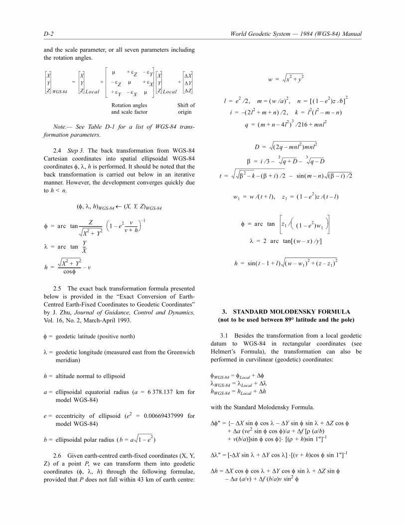
D-2 World Geodetic System — 1984 (WGS-84) Manual
and the scale parameter, or all seven parameters includingthe rotation angles.
Rotation angles Shift ofand scale factor origin
Note.— See Table D-1 for a list of WGS-84 trans-formation parameters.
2.4 Step 3. The back transformation from WGS-84Cartesian coordinates into spatial ellipsoidal WGS-84coordinates φ, λ, h is performed. It should be noted that theback transformation is carried out below in an iterativemanner. However, the development converges quickly dueto h < n.
(φ, λ, h)WGS-84 ← (X, Y, Z)WGS-84
2.5 The exact back transformation formula presentedbelow is provided in the “Exact Conversion of Earth-Centred Earth-Fixed Coordinates to Geodetic Coordinates”by J. Zhu, Journal of Guidance, Control and Dynamics,Vol. 16, No. 2, March-April 1993.
φ = geodetic latitude (positive north)
λ = geodetic longitude (measured east from the Greenwichmeridian)
h = altitude normal to ellipsoid
a = ellipsoidal equatorial radius (a = 6 378.137 km formodel WGS-84)
e = eccentricity of ellipsoid (e2 = 0.00669437999 formodel WGS-84)
b = ellipsoidal polar radius
2.6 Given earth-centred earth-fixed coordinates (X, Y,Z) of a point P, we can transform them into geodeticcoordinates (φ, λ, h) through the following formulae,provided that P does not fall within 43 km of earth centre:
3. STANDARD MOLODENSKY FORMULA(not to be used between 89° latitude and the pole)
3.1 Besides the transformation from a local geodeticdatum to WGS-84 in rectangular coordinates (seeHelmert’s Formula), the transformation can also beperformed in curvilinear (geodetic) coordinates:
φWGS-84 = φLocal + ΔφλWGS-84 = λLocal + ΔλhWGS-84 = hLocal + Δh
with the Standard Molodensky Formula.
Δφ" = {– ΔX sin φ cos λ – ΔY sin φ sin λ + ΔZ cos φ+ Δa (ve2 sin φ cos φ)/a + Δf [ρ (a/b)+ v(b/a)]sin φ cos φ}⋅ [(ρ + h)sin 1"]-1
Δλ" = [-ΔX sin λ + ΔY cos λ] ⋅[(v + h)cos φ sin 1"]-1
Δh = ΔX cos φ cos λ + ΔY cos φ sin λ + ΔZ sin φ– Δa (a/v) + Δf (b/a)v sin2 φ
XYZ WGS84
XYZ Local
μ ε+ Z εY–
εZ– μ ε+ Xε+ Y εX– μ
XYZ Local
ΔXΔYΔZ
+ +=
WGS-84
φ arc Z
X2 Y2+---------------------- 1 e2 v
v h+------------–⎝ ⎠
⎛ ⎞1–
tan=
λ arc YX---tan=
h X2 Y2+φcos
---------------------- v–=
b a 1 e2–=( )
w x2 y2+=
l e2 2 m w a⁄( )2 n,=,⁄ 1 e2–( )z b⁄[ ]2
= =
i 2l2 m n+ +( ) 2 k,⁄– l2 l2 m– n–( )= =
q m n 4l2–+( )3
216 mnl2+⁄=
D 2q mnl2–( )mnl2=
β i 3 q D+3
– q D–3
–⁄=
t β2 k– β i+( ) 2⁄– m n–( )sin β i–( ) 2⁄–=
w1 w t l+( ) z1,⁄ 1 e2–( )z t l–( )⁄= =
φ arc z1 1 e2–( )w1⎝ ⎠⎛ ⎞⁄tan=
λ 2 arc w x–( ) y⁄[ ]tan=
h t 1– l+( )sin w w1–( )2 z z1–( )2+=

Appendix D. Datum Transformation Formulas D-3
Δφ, Δλ, Δh = corrections to transform local geodetic datumto WGS-84. The units of Δφ and Δλ are arcseconds (''); the units of Δh are metres (m)
φ, λ, h = geodetic coordinates (old ellipsoid)h = H + N (where H is the orthometric height andN is the geoid undulation)
v = radius of curvature in the prime vertical
ρ = radius of curvature in the meridian
a, b = semi-major axis, semi-minor axis of the localgeodetic datum ellipsoid (b/a = 1 – f)
f = flattening of ellipsoid
ΔX, ΔY, ΔZ = shift of origin
Δa, Δf = difference between the semi-major axis and theflattening of the local geodetic datum ellipsoidand the WGS-84 ellipsoid, respectively (WGS-84minus Local)
e = eccentricity of ellipsoid (e2 = f(2 – f))
Note.— See Table B-1 for a list of reference ellipsoidsand parameters and Table D-1 for a list of datumtransformation parameters.
4. MULTIPLE REGRESSION EQUATION
4.1 To obtain a better fit over continental-size landareas than what could be achieved using the StandardMolodensky Formula with datum shifts ΔX, ΔY, ΔZ, thedevelopment of local geodetic datum to WGS-84 datumtransformation the Multiple Regression Equation wasinitiated.
Note.— Local geodetic datum to WGS-84 datum trans-formation Multiple Regression Equations for seven majorcontinental-size datums covering contiguous continental-sizeland areas with large distortion are provided in Departmentof Defense World Geodetic System 1984, Its Definition andRelationships with Local Geodetic Systems, NationalImagery and Mapping Agency, NIMA TR8350.2.
Δφ = A0 + A1 U + A2 V + A3 U2 + A4 UV + A5 V2 + K+ A99 U9V9
Δλ = B0 + B1 U + B2 V + B3 U2 + B4 UV + B5 V2 + K+ B99 U9V9
Δh = C0 + C1 U + C2 V + C3 U2 + C4 UV + C5 V2 + K+ C99 U9V9
A0, B0, C0 — constantAi (i = 1 ... 9) — unknowns to be determinedBi (i = 1 ... 9) — unknowns to be determinedCi (i = 1 ... 9) — unknowns to be determinedU = k (φ – φm) — normalized geodetic latitudeV = k (λ – λm) — normalized geodetic longitudek — scale factor, and degree to radian
conversionφm, λm — mean values of local geodetic datum
area (in degrees)
4.2 The main advantage lies in the modelling ofdistortion for a better fit in geodetic applications.
5. TRANSFORMATION PARAMETERS
Table D-1 gives a list of datum transformation parametersof existing national reference frames.

D-4 World Geodetic System — 1984 (WGS-84) Manual
Table D-1. Datum transformation parameters
Note 1.— 1" in the rotation angle is approximately equal to 31 m on the earth’s surface:
1" = 6 400 000 m × 3.141593 / (180 × 3600") = 31.03 m[1 NM = 1 852 m (so 1" = 30.48 m)]
Note 2.— 1 ppm = 10-6, i.e. 1 ppm is equivalent to approximately 6.4 m on the earth’s surface.
Reference datumTranslations (m) Rotations (") Scale µ
(ppm) Comments ΔX ΔY ΔZ εX εY εZ
WGS-84 ⋅ ⋅ ⋅ ⋅ ⋅ ⋅ ⋅WGS-72 0.0 0.0 4.5 0.0 0.0 –0.554 0.22ED 50 –87.0 –98.0 –121.0 ⋅ ⋅ ⋅ ⋅ED 79 –86.0 –98.0 –119.0 ⋅ ⋅ ⋅ ⋅ED 87 –82.5 –91.7 –117.7 0.1338 –0.0625 –0.047 0.045Austria NS 595.6 87.3 473.3 4.7994 0.0671 5.7850 2.555 Via ED 87Belgium 50 –55.0 49.0 –158.0 ⋅ ⋅ ⋅ ⋅Berne 1873 649.0 9.0 376.0 ⋅ ⋅ ⋅ ⋅CH-1903 660.1 13.1 369.2 0.8048 0.5777 0.9522 5.660Danish GI 1934 662.0 18.0 734.0 ⋅ ⋅ ⋅ ⋅Nouvelle Triangulation de France
–168.0 –60.0 320.0 ⋅ ⋅ ⋅ ⋅ GreenwichZero Meridian
Nouvelle Triangulation de France
–168.0 –60.0 320.0 ⋅ ⋅ 8414.03 ⋅ Paris ZeroMeridian
Potsdam 587.0 16.0 393.0 ⋅ ⋅ ⋅ ⋅ Via ED 50GGRS 87 199.6 –75.1 –246.3 0.0202 0.0034 0.0135 –0.015 55 –73.0 46.0 –86.0 ⋅ ⋅ ⋅ ⋅Ireland 65 506.0 –122.0 611.0 ⋅ ⋅ ⋅ ⋅Italy 1940 –133.0 –50.0 97.0 ⋅ ⋅ 44828.40 ⋅ Via ED 50
Rome Zero Meridian
Nouvelle Triangulation de Luxembourg
–262.0 75.0 25.0 ⋅ ⋅ ⋅ ⋅ Via ED 50
Netherlands 1921 719.0 47.0 640.0 ⋅ ⋅ ⋅ ⋅ Via ED 50OSGB 36 375.0 –111.0 431.0 ⋅ ⋅ ⋅ ⋅Portugal DLX 504.1 –220.9 563.0 ⋅ ⋅ –0.554 0.220 Via WGS-72Portugal 1973 –227.0 97.5 35.4 ⋅ ⋅ –0.554 0.220 Via WGS-72RNB 72 –104.0 80.0 –75.0 ⋅ ⋅ ⋅ ⋅ Via ED 50RT 90 424.3 –80.5 613.1 4.3965 –1.9866 5.1846 0.0NAD 27 –8.0 160.0 176.0 ⋅ ⋅ ⋅ ⋅ Mean solutionNAD 83 0.0 0.0 0.0 ⋅ ⋅ ⋅ ⋅

Appendix D. Datum Transformation Formulas D-5
FIGURE FOR APPENDIX D
Figure D-1. General principle of a datum transformation
P (φ λ Local Local Local Local Local, , h ; a , f )
P (φ λWGS-84 WGS-84 WGS-84 WGS-84 WGS-84, , h ; a , f )
Datumtransformation
formulas

�������

E-1
Appendix E
SURVEYING AND PHOTOGRAMMETRIC METHODS
1. SURVEYING
Definition of Surveying. A method of data collection byobservation and measurement.
Conventional surveying techniques
1.1 WGS-84 coordinates can be obtained bycollocating the point(s) with a WGS-84 (ITRF) station(measurement of relative coordinate differences).
1.2 Conventional surveying techniques determine:
a) directions and angles using a theodolite (accuracyof directions up to 0.01 mgon (0.1''). One gon isalso called the grad which is 1/400 of a circum-ference). The technique is also called triangulation;and
b) distances by EDM (electronic distance measure-ment). The accuracy derived can be up to 1 mm.The technique is also called trilateration.
Total stations
1.3 Modern total stations combine a self-recording,high-precision electronic theodolite with an EDM instrumentwhich is mounted (often) co-axially. A total station is set upover a reference point where coordinates are known and thetelescope is pointed towards a target/reflector to measuredistance, and horizontal and vertical angles. These arerecorded automatically either for immediate display (on-linefield computation capabilities) or for post-processing.
Spirit levelling
1.4 Figure E-1 shows the principle of spirit levelling,which is used to determine height differences relative to apoint of known (orthometric) height. The accuracy derivedcan be up to ±0.3 mm/√s (km). Although automated
instruments with complete digital data handling areavailable, the technique is very time-consuming, elaborateand expensive and the error propagation formula is onlyapplicable in a local area, say, up to 50 km. Hence, themain application of spirit levelling is with respect to thelocal area.
1.5 Heights that are derived using a trigonometrictechnique (measuring zenith or height angles) can beconsidered as “orthometric heights” (neglecting gravitydata and accuracy in decimetre level).
Advantages/disadvantages ofconventional surveying
1.6 Field operations with modern total stations take avery short time and a surveyor with an assistant can typicallysurvey up to 1 000 points per day in favourable meteoro-logical circumstances (theodolite and EDM instruments, aswell as spirit levelling instruments, are less efficient). Thistechnique, however, has a number of drawbacks.
1.7 The observations are limited by intervisibilitybetween theodolite and target and, to a lesser extent, byrange. The technique requires a number of evenly distributedcontrol reference stations, whose coordinates are eitherknown in advance or determined separately. Horizontalcontrol coordinates are normally computed by triangulationpoints and heights are provided by benchmarks, bothobtainable from the respective national mapping organiz-ation. National survey organizations, in turn, survey thesepoints and compute their coordinates or heights by using aseries of hierarchical networks, starting at primary level andbroken down successively into second order, third order, andso on. In a densely surveyed State, lower-order triangulationpoints are to be found, at best, at a density of, say, one every5 km. This is not sufficient for general surveying, andadditional control stations have to be established prior to adetailed survey by well-known control survey techniquessuch as triangulation, trilateration and traversing. GPSsurveying and photogrammetric techniques are, in thatrespect, becoming progressively more efficient.
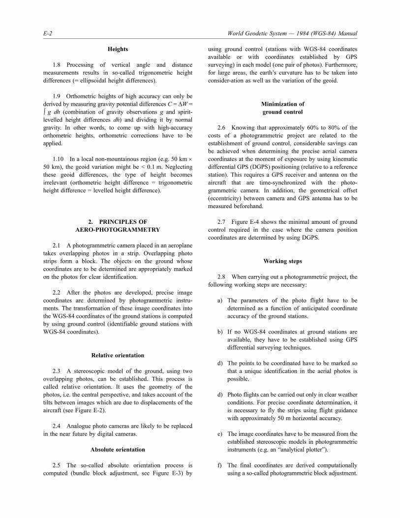
E-2 World Geodetic System — 1984 (WGS-84) Manual
Heights
1.8 Processing of vertical angle and distancemeasurements results in so-called trigonometric heightdifferences (= ellipsoidal height differences).
1.9 Orthometric heights of high accuracy can only bederived by measuring gravity potential differences C = ΔW =∫ g dh (combination of gravity observations g and spirit-levelled height differences dh) and dividing it by normalgravity. In other words, to come up with high-accuracyorthometric heights, orthometric corrections have to beapplied.
1.10 In a local non-mountainous region (e.g. 50 km ×50 km), the geoid variation might be < 0.1 m. Neglectingthese geoid differences, the type of height becomesirrelevant (orthometric height difference = trigonometricheight difference = levelled height difference).
2. PRINCIPLES OFAERO-PHOTOGRAMMETRY
2.1 A photogrammetric camera placed in an aeroplanetakes overlapping photos in a strip. Overlapping photostrips form a block. The objects on the ground whosecoordinates are to be determined are appropriately markedon the photos for clear identification.
2.2 After the photos are developed, precise imagecoordinates are determined by photogrammetric instru-ments. The transformation of these image coordinates intothe WGS-84 coordinates of the ground stations is computedby using ground control (identifiable ground stations withWGS-84 coordinates).
Relative orientation
2.3 A stereoscopic model of the ground, using twooverlapping photos, can be established. This process iscalled relative orientation. It uses the geometry of thephotos, i.e. the central perspective, and takes account of thetilts between images which are due to displacements of theaircraft (see Figure E-2).
2.4 Analogue photo cameras are likely to be replacedin the near future by digital cameras.
Absolute orientation
2.5 The so-called absolute orientation process iscomputed (bundle block adjustment, see Figure E-3) by
using ground control (stations with WGS-84 coordinatesavailable or with coordinates established by GPSsurveying) in each model (one pair of photos). Furthermore,for large areas, the earth’s curvature has to be taken intoconsider-ation as well as the variation of the geoid.
Minimization ofground control
2.6 Knowing that approximately 60% to 80% of thecosts of a photogrammetric project are related to theestablishment of ground control, considerable savings canbe achieved when determining the precise aerial cameracoordinates at the moment of exposure by using kinematicdifferential GPS (DGPS) positioning (relative to a referencestation). This requires a GPS receiver and antenna on theaircraft that are time-synchronized with the photo-grammetric camera. In addition, the geometrical offset(eccentricity) between camera and GPS antenna has to bemeasured beforehand.
2.7 Figure E-4 shows the minimal amount of groundcontrol required in the case where the camera positioncoordinates are determined by using DGPS.
Working steps
2.8 When carrying out a photogrammetric project, thefollowing working steps are necessary:
a) The parameters of the photo flight have to bedetermined as a function of anticipated coordinateaccuracy of the ground stations.
b) If no WGS-84 coordinates at ground stations areavailable, they have to be established using GPSdifferential surveying techniques.
d) The points to be coordinated have to be marked sothat a unique identification in the aerial photos ispossible.
d) Photo flights can be carried out only in clear weatherconditions. For precise coordinate determination, itis necessary to fly the strips using flight guidancewith approximately 50 m horizontal accuracy.
e) The image coordinates have to be measured from theestablished stereoscopic models in photogrammetricinstruments (e.g. an “analytical plotter”).
f) The final coordinates are derived computationallyusing a so-called photogrammetric block adjustment.

Appendix E. Surveying and Photogrammetric Methods E-3
g) Verification of the photogrammetrically-derivedcoordinates has to be done using selected fieldchecks (GPS or conventional surveying).
Advantages/disadvantages
2.9 The advantages of aero-photogrammetry are that:
a) a photogrammetric survey can cover a large area inone flight; and
b) the analogue photos which are taken for coordinatedetermination contain a lot of additional analogueinformation which might be useful for other tasks(e.g. interpretation).
2.10 The disadvantages may be that:
a) since flights should be carried out when thevegetation is low and the weather is clear, longwaiting times may occur;
b) it might not be economical compared to otherterrestrial techniques;
c) certain restrictions may arise due to flightconstraints and air traffic control; and
d) the public release of photos may need approval bygovernmental or military organizations.

E-4 World Geodetic System — 1984 (WGS-84) Manual
FIGURES FOR APPENDIX E
Figure E-1. Principle of spirit levelling
Figure E-2. Overlapping vertical photos taken by an aerial camera
Line of sight1.121.96
A
B0.84
a´´a´ ya´´ya´
zA
yA
xA
A
S1
zy
xBx
ByBz
S2

Appendix E. Surveying and Photogrammetric Methods E-5
Figure E-3. Bundle block adjustment
Figure E-4. Minimal amount of ground control by using DGPS
zyx

�������

F-1
Appendix F
MAP PROJECTIONS
1. INTRODUCTION
Advances in information technology have given rise toautomatic cartography and, hence, to digital mapping. Ahard copy analogue map can now be digitized andtransformed into a database, which can then be used for avariety of computer-aided design (CAD) applications inplanning, civil engineering and geographical informationsystems (GIS). National surveying and mapping organiz-ations are now well advanced in digitizing their nationalmapping, typically at scales from 1:1 000 for urban areasand up to 1:10 000 for rural areas.
2. GENERAL PRINCIPLE OFMAP PROJECTIONS
2.1 It is necessary to determine the functions f1 and f2which map the ellipsoidal (or spherical) coordinates φ, λonto a plane with rectangular coordinates X, Y.
X = f1(φ, λ)
Y = f2(φ, λ)
2.2 f1 and f2 can be functions of latitude, longitude, orboth. Each map projection has unique equations for X andY. In other words, there is a one-to-one correspondencebetween the earth and the map.
Note.— Some map projections show the same meridiantwice, because the geographical poles are represented bylines instead of points or because certain parts of theearth’s surface cannot be shown on the projection. Thesepeculiarities arise from the simple fact that a sphere has acontinuous surface, whereas a plane map must have aboundary.
2.3 The correspondence between points on the surfaceof the earth and the plane cannot be exact. In the first place,a scale change must occur. In the second place, the curved
surface of the earth cannot be fitted to a plane withoutintroducing some deformation or distortion which isequivalent to stretching or tearing the curved surface.
3. TYPES OF PROJECTIONS
3.1 Local surveys are usually computed in plane metriccoordinates. These coordinates are obtained by mapping thereference ellipsoid to the plane by applying one of the well-known map projections. The surveyor mainly works in thisplane coordinate system (x or northings, y or eastings). Thecoordinates of surveyed objects, obtained by using, forexample, EDM equipment and theodolites, are most easilycomputed by applying plane computation formulae.
3.2 Air navigation, on the other hand, operates usinggeographic coordinates (latitude, longitude). Therefore theproblem is to derive geographic coordinates as a functionof plane coordinates. This problem can be solved byapplying the inverse map projection formulae to theeastings and northings. Application of inverse mapprojection requires that the type of national map projectionbe clearly defined in mathematical terms.
3.3 Projections can be classified as mapping of theearth onto the plane of:
a) an azimuthal plane;
b) a tangent cone; or
c) a tangent cylinder.
3.4 Plane, cone and cylinder can be in a normal,transverse or oblique position attached to the earth. Inaddition, the surfaces of the plane, cone and cylinder canintersect the ellipsoid (or sphere) so that there are twolines of contact. These projections are called secantprojections.

F-2 World Geodetic System — 1984 (WGS-84) Manual
4. PROPERTIES OF PROJECTIONS
Equidistance
4.1 One particular scale is made equal to the principalscale throughout the map. Usually, this is the meridionalscale.
Equivalence
4.2 An equal area map is one in which a × b = 1 (aand b are the axes of the ellipse of distortion).
Conformal map
4.3 A conformal map is one in which a = b at allpoints of the map.
Geodetic map projections
4.4 Geodetic map projections differ from thecartographic ones as follows:
a) The application is mainly with respect to large- ormedium-scale maps.
b) The reference ellipsoid is the one used by thenational surveying agency.
c) The graticule lines on the map represent geodeticcoordinates (in contrast to geographic coordinateson cartographic graticules).
d) Geodetic maps should represent the results ofsurveying (e.g. northing, easting).
4.5 At present, mainly conformal transversecylindrical projections are used (Gauss’ coordinates).
5. SPHERICAL PROJECTION FORMULAE
Transverse cylindric Mercator
5.1 A transverse cylindric Mercator projection it is aconformal projection. The meridian is the line of zerodistortion and the principal scale is preserved along thismeridian. At the equator the projection is also equidistant.There is no representation of the poles. The projection maybe either tangential or secant by the use of a centralmeridian scale factor. The X- (north) axis is towards the
North Pole along the central meridian and the Y- (east) axisis directed towards the east. The origin is at a point on thecentral meridian which may be arbitrarily selected by thedefinition of a latitude of origin φ0.
X = Rlu(sec θ + tan θ)
Y = R(cos-1(tan θ cot(λ – λ0)-φ0))
θ = sin-1(cos φ sin(λ – λ0))
R =
φ0, λ0 = latitude of origin point,longitude of central meridian
F0 = central meridian scale factor(F0 = 0 for tangential)
Stereographic polar
5.2 An orthomorphic zenithal (plane) projectionwhich is tangential at the North Pole. The Cartesian axesare oriented with the X- (north) axis pointing away fromthe “central” meridian, and the Y- (east) axis pointingtowards 90° east of the central meridian.
R = radius of the sphere, as given by
λ0 = longitude of central meridian
Stereographic oblique
5.3 Similar to the Stereographic polar with theexception that the plane is tangential to the sphere at anypoint. The X- (north) axis is directed towards the NorthPole and the Y- (east) axis to the east.
φ0, λ0 = latitude and longitude of tangential point
X =–2R cos φ cos (λ – λ0)
1 + sin φ
Y =2R cos φ cos (λ – λ0)
1 + sin φ
X = 2Rsin φ cos φ0 – cos φ sin φ0 cos(λ – λ0)
1 + sin φ sin φ0 + cos φ cos φ0 cos(λ – λ0)
Y = 2Rcos φ sin(λ – λ0)
1 + sin φ sin φ0 + cos φ cos φ0 cos(λ – λ0)
F0 vρ
R νρ=

Appendix F. MAP Projections F-3
Lambert conical,one standard parallel
5.4 An orthomorphic conical normal projection withthe cone tangential to the sphere along one standard parallelof latitude. The Cartesian axes are oriented with the X-(north) axis towards the North Pole and the Y- (east) axisto the east.
X = r0 – r cos θ
Y = r sin θ
θ = (λ – λ0)sin φ0
r0 = R cot φ0
φ0, λ0= latitude of standard parallel,longitude of central meridian
Lambert conical,two standard parallel
5.5 Similar to the tangential case but with a secantcone which cuts the sphere at two standard parallels, φ1 andφ2. The origin of the Cartesian coordinates is at an impliedmid-latitude φ0.
X = r0 – r cos θ
Y = r sin θ
θ = (λ – λ0)sin φ0
6. ELLIPSOIDAL PROJECTIONFORMULAE
Note.— For the ellipsoidal formulae, the descriptionsand definitions of Cartesian axes are the same as for thespherical formula.
6.1 Stereographic polar
X = –r cos θ
Y = r sin θ
θ = λ – λ0
λ0 = longitude of central meridian
a = semi-major axis of ellipsoid
e = eccentricity of ellipsoid
6.2 Stereographic oblique
sin h = sin φ sin φ0 + cos φ cos φ 0 cos(λ – λ0)
f0, l0 = latitude of tangential pole,longitude of tangential pole
6.3 Lambert conical,one standard parallel
X = r0 – r cos θ
Y = r sin θ
θ = (λ – λ0)sin φ0
r0 = v0 cot φ0sin φ0 =
lu cos φ1 – lu cos φ2
lu tan(45 – 0.5φ1) – lu tan(45 – 0.5φ2)
r r0
45 0.5φ–( )tan45 0.5φ0–( )tan
--------------------------------------
⎝ ⎠⎜ ⎟⎜ ⎟⎜ ⎟⎛ ⎞
φ0sin
=
R vρ=
l0R φ1cos
φ0sin--------------------- 45 0.5φ0–( )tan45 0.5φ1–( )tan
--------------------------------------⎝ ⎠⎜ ⎟⎛ ⎞
φ0sin
=
rR φ1cos
φ0sin--------------------- 45 0.5φ0–( )tan45 0.5φ1–( )tan
--------------------------------------⎝ ⎠⎜ ⎟⎛ ⎞
φ0sin
=
r0 2a 1 e+( )
1–2 1 e–( )-------------------
1 e–( )
1–2 1 e–( )-------------------
φcos1 φsin+--------------------⎝ ⎠
⎛ ⎞ 1 e φsin+1 e φsin–-----------------------⎝ ⎠
⎛ ⎞ 1 2e⁄=
X 2v01 e+1 e–------------⎝ ⎠
⎛ ⎞ 1 2⁄– φ φ0 φ φ0 λ λ0–( )cossincos–cossin
1 hsin+----------------------------------------------------------------------------------------------------⎝ ⎠⎜ ⎟⎛ ⎞
=
1 e hsin+1 e hsin–------------------------------⎝ ⎠
⎛ ⎞ 1 2⁄–
Y 2v01 e+1 e–------------⎝ ⎠
⎛ ⎞ 1 2⁄– φ λ λ0–( )sincos
1 hsin+--------------------------------------------⎝ ⎠
⎜ ⎟⎛ ⎞ 1 e hsin+
1 e hsin–------------------------------⎝ ⎠
⎛ ⎞ 1 2⁄–=
v0a
1 e2 2 φ0sin–( )1 2⁄---------------------------------------------------=

F-4 World Geodetic System — 1984 (WGS-84) Manual
f0, l0 = latitude of standard parallel,longitude of the central meridian
6.4 Lambert conical, two standard parallel
X = r0 – r cos θ
Y = r sin θ
θ = (λ – λ0)sin φ0
6.5 Transverse cylindric Mercator
6.5.1 The transverse Mercator projection from theellipsoidal surface is usually expressed as a number ofseries expansions.
X = M + (λ – λ0)2 A + (λ – λ0)4 B + (λ – λ0)6C
Y = (λ – λ0) D + (λ – λ0)3 E + (λ – λ0)5F
6.5.2 The central meridian scale factor F0 is applied bymultiplying the semi-major axis a by F0 before calculatingany other quantities.
v1 =a
(1 – e2 sin2 φ1)1/2
v2 =a
(1 – e2 sin2 φ1)1/2
r r0
45 0.5φ–( ) 1 e φsin+1 e φsin–------------------------------⎝ ⎠
⎛ ⎞1 2e⁄
tan
45 0.5φ0–( )1 e φ0sin+1 e φ0sin–--------------------------------⎝ ⎠
⎛ ⎞1 2e⁄
tan--------------------------------------------------------------------------------------
⎝ ⎠⎜ ⎟⎜ ⎟⎜ ⎟⎜ ⎟⎛ ⎞
φ0sin
=
v0a
1 e2 2 φ0sin–( )1 2⁄
---------------------------------------------------=
r0 v2φ2cosφ2sin--------------
45 0.5φ0–( )1 e φ0sin+1 e φ0sin–--------------------------------⎝ ⎠
⎛ ⎞1 2e⁄
tan
45 0.5φ2–( )1 e φ2sin+1 e φ2sin–--------------------------------⎝ ⎠
⎛ ⎞1 2e⁄
tan--------------------------------------------------------------------------------------
⎝ ⎠⎜ ⎟⎜ ⎟⎜ ⎟⎜ ⎟⎛ ⎞
φ0sin
=
r v2φ2cosφ0sin--------------
45 0.5φ–( ) 1 e φsin+1 e φsin–------------------------------⎝ ⎠
⎛ ⎞1 2e⁄
tan
45 0.5φ0–( )1 e φ0sin+1 e φ0sin–--------------------------------⎝ ⎠
⎛ ⎞1 2e⁄
tan--------------------------------------------------------------------------------------
⎝ ⎠⎜ ⎟⎜ ⎟⎜ ⎟⎜ ⎟⎛ ⎞
φ0sin
=
φ0luv1 φ1 luv2 φ2cos–cos
lu 45 0.5φ1–( )1 e φ1sin+1 e– φ1sin---------------------------------⎝ ⎠
⎛ ⎞1 2e⁄
tan⎝ ⎠⎜ ⎟⎛ ⎞
–
------------------------------------------------------------------------------------------------------------sin
lu 45 0.5φ2–( )1 e φ2sin+1 e– φ2sin---------------------------------⎝ ⎠
⎛ ⎞1 2e⁄
tan⎝ ⎠⎜ ⎟⎛ ⎞
--------------------------------------------------------------------------------------------------------------------------
M = b(1 + n + 5
n2 +5
n2) (φ – φ0)4 4
M = – (3n + 3n2 + 21
n3)sin (φ – φ0)cos (φ + φ0)8
M = + (15
n2 +15
n3)sin 2 (φ – φ0)cos 2 (φ + φ0)8 8
M = – 25
n3 sin 3 (φ – φ0)cos 3 (φ + φ0)24
A =v
sin φ cos φ2
B =v
sin φ cos3 φ(5 – tan2 φ + 9η2)24
C =v
sin φ cos5 φ(61 – 58 tan3 φ + tan4 φ)720
D = v cos φ
E =v
cos3 φ(v
– tan2 φ)6 ρ
F =v
cos5 φ(5 – 18 tan2 φ + tan4 φ + 14η2 – 58 tan2 φη2)120
v =a
(1 – e2 sin2 φ)1/2
ρ =a(1 –e2)
(1 – e2 sin φ)3/2
η =a – ba + b
b = a(1 – f)
η2 =v
– 1ρ

Appendix F. MAP Projections F-5
7. GAUSS-KRÜGER PROJECTION
The Gauss-Krüger projection is identical to the conformalMercator projection but the position of the cylinder istransverse. The reference surface is the Bessel ellipsoid andthe central meridian is equidistant. The y-coordinates(eastings) are enlarged due to the convergence of the x-axes(northings). In order to keep this distortion in reasonablelimits, zones of 3° width (in longitude) are established withthe central meridian lying in the middle of each zone. Themeridional strip systems have the following northings andeastings:
Northing: Distance from the equator.
Easting: In order to avoid negative signs, each centralmeridian has the constant y = 500 000 m. Thefirst two digits represent the zone numberwhich is the longitude of the central meridiandivided by three.
Example: The tower of the town hall of Berlin has thegeographical coordinates:
λ = 13°24''36.01'' φ = 52°31''11.65''
The corresponding Gauss-Krüger coordinateswith respect to the central meridian of λ = 12°are:
E = 45 95 696.00 m N = 5821529.20 m.
8. UNIVERSAL TRANSVERSE MERCATOR(UTM) SYSTEM
The Universal Transverse Mercator (UTM) system, oftenused for military maps, comprises the following features:
a) The projection is the Gauss-Krüger version of theTransverse Mercator intended to provide worldcoverage between the latitudes 84°N and 80°S.
b) The reference ellipsoid is the International 1924; theunit of measure is the International Metre.
c) Each zone is 6° of longitude in width. The first zonehas its western edge on the meridian 180° and thezones proceed eastwards to zone 60 which has itseastern edge at 180° longitude. The central meridianof each zone is therefore: 177° in zone 1; 171° inzone 2; and 168° in zone 3, etc.
d) The origin of each zone is the point on the equatorwhere it is intersected by the central meridian of thezone. Each zone extends as far polewards as 84° Nand 80° S (initially these limits were set at 80° Nand 80° S).
e) The eastings of the origin of each zone are assignedthe value of 500 000 m.
f) The scale factor on the central meridian is 0.9996.
g) The UTM employs five different figures forspecific areas.

�������

G-1
Appendix G
SAMPLE QUESTIONNAIRE
Survey inventory related to WGS-84 implementation
Notes on the completion of Parts I and II:
1. Part I should be completed by national aviation administrations.
2. Part I, 25, items i to ix, should be completed for each navigation aid.
3. Part II should be distributed by national aviation administrations to aerodrome/heliport authorities for completion — one questionnaire for each aerodrome/heliport. The cover page is to be completed by national administrations.
4. Initially, Part II should be completed for aerodromes/heliports that have established instrument approach procedure(s) for the runway(s).
5. For aerodromes/heliports where visual approach procedures only are established, the requirement is for information on the aerodrome/heliport reference point (ARP).
6. Parts I and II have been designed so that the responses can be scanned automatically into a digital format. The majority of the questions are in a multiple-choice format. The scanning and formatting of the data will permit analysis using a PC-based tool. This PC programme is available to States from ICAO.
7. Blank templates of the questionnaires are available from ICAO. These may be used by national administrations to insert text in their national language. It is important that the format and layout be maintained so that translated questionnaires may be scanned and analysed by the PC programme referred to in 6 above.

G-2 World Geodetic System — 1984 (WGS-84) Manual
Part I — En-route navigation aids
State
Civil Aviation Administration
Address
Contact name
Telephone
Facsimile

Appendix G. Sample questionnaire G-3
Navigation Aid Survey Inventory
Questionnaire
Part I — En-route navigation aids
(DME, VOR, DME/VOR, NDB, VORTAC and TACAN)
1. By which organization is coordination of navigation aids performed?
2. Is a written specification used for the method of measurement?
3. Which facilities are surveyed?
4. Is coordination done by instrument survey or by graphical methods?
[ ] National aviation administration’s internal survey unit[ ] Aerodrome/heliport staff surveyors[ ] National mapping agency[ ] Local government survey unit[ ] Military survey department[ ] Private survey contractor[ ] Other — please specify
[ ] Yes [ ] No
DME [ ] Yes [ ] NoVOR [ ] Yes [ ] NoVOR/DME [ ] Yes [ ] NoNDB [ ] Yes [ ] NoVORTAC [ ] Yes [ ] NoTACAN [ ] Yes [ ] No
DME [ ] Instrument survey [ ] Graphical methodVOR [ ] Instrument survey [ ] Graphical methodVOR/DME [ ] Instrument survey [ ] Graphical methodNDB [ ] Instrument survey [ ] Graphical methodVORTAC [ ] Instrument survey [ ] Graphical methodTACAN [ ] Instrument survey [ ] Graphical method

G-4 World Geodetic System — 1984 (WGS-84) Manual
5. If coordinates are obtained graphically from map products, what map scale (or nearest equivalent) is generally used?
6. To what accuracy are the coordinates determined?
Note.— This may differ from the resolution quoted in the AIP.
INFRASTRUCTURE
7. If coordinates are extracted from a map, is it known on which datum the map is based?
8. Is the information in 7 above recorded as part of the survey?
9. If instrument surveys are performed,
a) Is a record made of the reference frame used?
b) Are permanent survey stations established as part of the survey?
DME VOR DME/VOR NDB VORTAC TACAN>1/5 000 [ ] [ ] [ ] [ ] [ ] [ ]1/5 000 [ ] [ ] [ ] [ ] [ ] [ ]1/10 000 [ ] [ ] [ ] [ ] [ ] [ ]1/20 000 [ ] [ ] [ ] [ ] [ ] [ ]1/25 000 [ ] [ ] [ ] [ ] [ ] [ ]1/50 000 [ ] [ ] [ ] [ ] [ ] [ ]1/100 000 [ ] [ ] [ ] [ ] [ ] [ ]1/250 000 [ ] [ ] [ ] [ ] [ ] [ ]<1/250 000 [ ] [ ] [ ] [ ] [ ] [ ]
DME VOR DME/VOR NDB VORTAC TACAN>1 NM [ ] [ ] [ ] [ ] [ ] [ ]1 NM [ ] [ ] [ ] [ ] [ ] [ ]0.1 NM [ ] [ ] [ ] [ ] [ ] [ ]100 m [ ] [ ] [ ] [ ] [ ] [ ]10 m [ ] [ ] [ ] [ ] [ ] [ ]1 m [ ] [ ] [ ] [ ] [ ] [ ]
[ ] Yes [ ] No
[ ] Yes [ ] No
[ ] Yes [ ] No
[ ] Yes [ ] No

Appendix G. Sample questionnaire G-5
QUALITY CONTROL
10. Is the determination of the geographical coordinates of navigation aids covered by a formal system of quality assurance, such as ISO 9000 or equivalent?
11. What classification of staff is used for coordinating en-route navaids?
12. Is specific training given for the particular task of surveying navigation aids?
13. Are field inspections undertaken to verify the location of the navigation aids and, if yes, are they part of an ongoing programme for inspection?
14. Are such inspections, or similar inspections, part of an ongoing programme for inspection or calibration?
15. Where coordinates are supplied by other government agencies, is any further form of checking performed?
RECORDS AND ARCHIVES
16. Are comprehensive records kept on positioning and coordinate data ?
17. Are such records free of inconsistencies?
18. Is it possible to trace the data and the method of the survey/coordination of individual navaids?
[ ] Yes — please specify[ ] No
[ ] Professional surveyors[ ] Qualified cartographers or draughtsmen[ ] Qualified technicians[ ] Junior grade staff[ ] Untrained staff[ ] Not known
[ ] Yes [ ] No
[ ] Yes [ ] No
[ ] Yes [ ] No
[ ] Yes [ ] No
[ ] Yes [ ] No
[ ] Yes [ ] No
[ ] Yes [ ] No
[ ] Yes [ ] No

G-6 World Geodetic System — 1984 (WGS-84) Manual
19. Are the survey records held centrally and, if yes, are they easily accessible?
20. Are the survey records held on computer?
21. Are the survey records subject to regular maintenance?
22. In the case of collocated navigation aids (VOR/DME), is it known to which facility the published coordinates relate?
23. Is the physical separation of such pairs of facilities known?
24. Where central records of precise coordinates of navigation aids are kept, are the published AIP coordinates checked for consistency?
CONFIRMATION OF AIP ENTRY
25. Please indicate in Column A the number of navaids for which coordinates are published. In Column B state the number of navaids for which the coordinates are determined by the national civil aviation administration itself.
[ ] Yes [ ] No
[ ] Yes [ ] No
[ ] Yes [ ] No
[ ] Yes [ ] No
[ ] Yes [ ] No
[ ] Yes [ ] No
[ ] Yes [ ] No
AID Column A Column B
DME
VOR
VOR/DME
NDB
VORTAC
TACAN

Appendix G. Sample questionnaire G-7
The following information is required for each DME, VOR, DME/VOR, TACAN and VORTAC. The information is notrequired for NDBs.
(i) Identifier
(ii) Type of aid
[ ] DME [ ] VOR [ ] DME/VOR[ ] TACAN [ ] VORTAC
(iii) Is there any documentary record of the date of survey (i.e. date on which coordinates were determined)?
[ ] Yes [ ] No
(iv) Method of survey, please specify.
(v) To which geodetic datum do the coordinates refer?
[ ] WGS-84 [ ] National Mapping Datum[ ] ED 50 [ ] Not known
(vi) If the answer to (v) was national mapping datum, please state its name.
(vii) Are original survey observations available?
[ ] Yes [ ] No
(viii) In the case of VOR, TACAN and VORTAC, please state, if available, the value of the SITE DECLINATION (VARIATION) set at the last calibration.
DEGREES.XX [ ] East [ ] West
Date of last calibration
(ix) For collocated aids (e.g. VOR/DME), do the coordinates relate to the distance measuring element?
[ ] Yes [ ] No

G-8 World Geodetic System — 1984 (WGS-84) Manual
Part II — Aerodrome/heliport points
Aerodrome/heliport ICAOlocation indicator
Aerodrome/heliport
Address
Contact name
Telephone
Facsimile

Appendix G. Sample questionnaire G-9
Navigation Aid Survey Inventory
Questionnaire
Part II — Aerodrome/heliport points
This section to be completed by national administrations.
First name
Family name
Position
Address
Telephone
Facsimile

G-10 World Geodetic System — 1984 (WGS-84) Manual
This section to be completed by the technical officer responsible for providing survey details.
First name
Family name
Position
Address
Telephone
Facsimile

Appendix G. Sample questionnaire G-11
SURVEY CONTROL NETWORK
1. Is there an existing survey control network at the aerodrome/heliport?
2. If yes, who installed and surveyed the network?
3. State the name of the survey organization. (If more than one survey organization has been involved, state the name of the organization having done the most work.)
4. State the age of the aerodrome/heliport survey control network, in years.
5. To which geodetic datum or control frame is the network referenced?
6. To which order of geodetic network is the aerodrome/heliport survey network connected?
7. Name of geodetic network.
8. Method of connection.
[ ] Yes [ ] No [ ] Not known
[ ] National aviation administration’s internal survey unit [ ] Aerodrome/heliport staff surveyor[ ] National mapping agency[ ] National geodetic agency[ ] Local government survey unit[ ] Military survey department[ ] Private survey contractor[ ] Other — specify
[ ] [ ] [ ] [ ] [ ] [ ] [ ] [ ] [ ] [ ] [ ] [ ]<1 1 2 3 4 5 6 7 8 9 10 >10
[ ] WGS-84 [ ] National Mapping Datum[ ] ED 50 [ ] Not known
[ ] Primary [ ] Secondary [ ] Tertiary
[ ] Static GPS [ ] EDM Traverse[ ] Triangulation [ ] Not known

G-12 World Geodetic System — 1984 (WGS-84) Manual
9. How many stations are in place at the aerodrome/heliport?
10. What is the relative survey accuracy of the aerodrome/heliport survey control network?
11. Types of survey control markers (monuments) used on network.
Concrete:
Earth anchor:
Surface mark (rivet, stud, metal plate, etc.):
12. Are survey station descriptions available?
13. Was the survey performed in accordance with the guidance in this manual?
14. Is the survey work performed in accordance with a quality assurance scheme (such as ISO 9000)?
15. Is a survey report available?
16. Has a record been kept of the original survey observations?
[ ] [ ] [ ] [ ] [ ] [ ] [ ] [ ] [ ] [ ] [ ] [ ]<1 1 2 3 4 5 6 7 8 9 10 >10
[ ] < 1 metre [ ] < 0.1 metre [ ] < 0.02 metre
[ ] [ ] [ ] [ ] [ ] [ ] [ ] [ ] [ ] [ ] [ ] [ ]<1 1 2 3 4 5 6 7 8 9 10 >10
[ ] [ ] [ ] [ ] [ ] [ ] [ ] [ ] [ ] [ ] [ ] [ ]<1 1 2 3 4 5 6 7 8 9 10 >10
[ ] [ ] [ ] [ ] [ ] [ ] [ ] [ ] [ ] [ ] [ ] [ ]<1 1 2 3 4 5 6 7 8 9 10 >10
[ ] Yes [ ] No [ ] Not known
[ ] Yes [ ] No [ ] Not known
[ ] Yes — specify [ ] No scheme
[ ] Yes [ ] No [ ] Not known
[ ] Yes [ ] No [ ] Partial

Appendix G. Sample questionnaire G-13
17. Were independent checks made on the survey?
18. Which organization made the checks?
19. Were records kept of the checks?
AERODROME OBSTACLES
20. Which organization performed the obstacle survey?
21. State the name of survey organization. (If more than one survey organization has been involved, state the name of the organization having done the most work.)
22. State how frequently, in years, the aerodrome/heliport obstacle survey is performed?
23. How long ago, in years, was the last aerodrome/heliport obstacle survey carried out?
24. To which geodetic datum is the aerodrome/heliport obstacle survey referenced?
25. Are the obstacle coordinates obtained by original instrument survey or by graphical means from existing mapping?
[ ] Yes [ ] No [ ] Not known
[ ] Yes [ ] No [ ] Not known
[ ] National aviation administration’s internal survey unit [ ] Aerodrome/heliport staff surveyor[ ] National mapping agency[ ] National geodetic agency[ ] Local government survey unit[ ] Military survey department[ ] Private survey contractor[ ] Other — specify
[ ] [ ] [ ] [ ] [ ] [ ] [ ] [ ] [ ] [ ] [ ] [ ]<1 1 2 3 4 5 6 7 8 9 10 >10
[ ] [ ] [ ] [ ] [ ] [ ] [ ] [ ] [ ] [ ] [ ] [ ]<1 1 2 3 4 5 6 7 8 9 10 >10
[ ] National datum [ ] Local datum
[ ] Instrument survey [ ] Existing mapping

G-14 World Geodetic System — 1984 (WGS-84) Manual
26. Was the survey performed in accordance with any declared specifications?
27. Do full survey records for the aerodrome/heliport obstacles exist?
28. Is the survey work performed in accordance with a quality assurance scheme (such as ISO 9000)?
29. Is the survey report available?
30. Has a record been kept of the original survey observations?
31. Were independent checks made on the survey?
32. Which organization made the checks?
AERODROME/HELIPORT NAVIGATION ELEMENTS
33. Which organization performed the aerodrome/heliport navigation elements survey?
34. State the name of survey organization. (If more than one survey organization has been involved, state the name of the organization having done the most work.)
[ ] Yes [ ] No [ ] Not known
[ ] Yes [ ] No [ ] Not known
[ ] Yes — specify [ ] No scheme
[ ] Yes [ ] No [ ] Not known
[ ] Yes [ ] No [ ] Not known
[ ] Yes [ ] No [ ] Not known
[ ] National aviation administration’s internal survey unit [ ] Aerodrome/heliport staff surveyor[ ] National mapping agency[ ] National geodetic agency[ ] Local government survey unit[ ] Military survey department[ ] Private survey contractor[ ] Other — specify

Appendix G. Sample questionnaire G-15
RUNWAY THRESHOLDS
35. How many runway thresholds are on the aerodrome/heliport?
36. How many runways with precision approach facilities are on the aerodrome/heliport?
37. How many thresholds have been surveyed?
38. To which accuracy have these thresholds been surveyed?
[ ] [ ] [ ] [ ] [ ] [ ] [ ] [ ] [ ] [ ] [ ] [ ]<1 1 2 3 4 5 6 7 8 9 10 >10
[ ] [ ] [ ] [ ] [ ] [ ] [ ] [ ] [ ] [ ] [ ] [ ]<1 1 2 3 4 5 6 7 8 9 10 >10
[ ] [ ] [ ] [ ] [ ] [ ] [ ] [ ] [ ] [ ] [ ] [ ]<1 1 2 3 4 5 6 7 8 9 10 >10
[ ] < 10 metres [ ] < 3 metres [ ] < 1 metre [ ] < 0.1 metre

�������

BIBLIOGRAPHY
Ashkenazi, V., S.A. Crane, W.J. Preis and J. Williams. The 1980 Readjustment of the Triangulation of the United Kingdomand the Republic of Ireland — OS(SN)80. Ordnance Survey Professional Papers, New Series, No. 31, 1984.
Ashkenazi, V., T. Moore and C. Hill. DATUM: A Report and Software Package for the Transformation and Projection ofCoordinates. United Kingdom: Institute of Engineering Surveying and Space Geodesy, University of Nottingham, revisedDecember 1993, EEC Report 237, 12/1990.
Helmert, F.R. Die mathematischen und physikalischen Theorien der Höheren Geodäsie. Leipzig: B.G. Teubner, 1880.
Hofmann-Wellenhof, B., H. Lichtenegger and H.J. Collins. Global Positioning System. New York: Springer-Verlag Wien,1993.
Kahmen, H., and W. Faig. Surveying. Berlin, New York: Walter de Gruyter, 1988.
Kraus, K., and P. Waldhäusl. Photogrammetrie. Band 1. Grundlagen und Standardverfahren. Ferd. Bonn: Dümmlers Verlag,1994.
Maling, D.H. Coordinate Systems and Map Projections. Pergamon Press, 1992.
Torge, W. Geodesy. Berlin, New York: Walter de Gruyter, 1991.
Vanicek, P. and E. Krakiwsky. Geodesy: The Concepts. Amsterdam, New York, Oxford: North Holland PublishingCompany, 1982.
Zhu, J., Exact Conversion of Earth-Centred Earth-Fixed Coordinates to Geodetic Coordinates. Journal of Guidance, Control,and Dynamics. Vol. 16, No. 2, March-April 1993.
National Imagery and Mapping Agency, Department of Defense World Geodetic System 1984, Its Definition andRelationships with Local Geodetic Systems. NIMA TR8350.2.
National Geodetic Survey. Geodetic Glossary (1986).
— END —

�������

�������


![OASIS Specification Template€¦ · Web viewGeographic locations in CAP are defined using [WGS 84] (World Geodetic System 1984), equivalent to EPSG (European Petroleum Survey Group)](https://img.pdfslide.us/doc/110x75/5ed3d556e581cf2aa161c971/oasis-specification-template-web-view-geographic-locations-in-cap-are-defined-using.jpg)