Embed Size (px)
DESCRIPTION
F1 in Schools World Championship 2010 Rule and Regulation
Citation preview
1
A life-changing experience…
Rules & Regulations 2010 World Championship Season
2
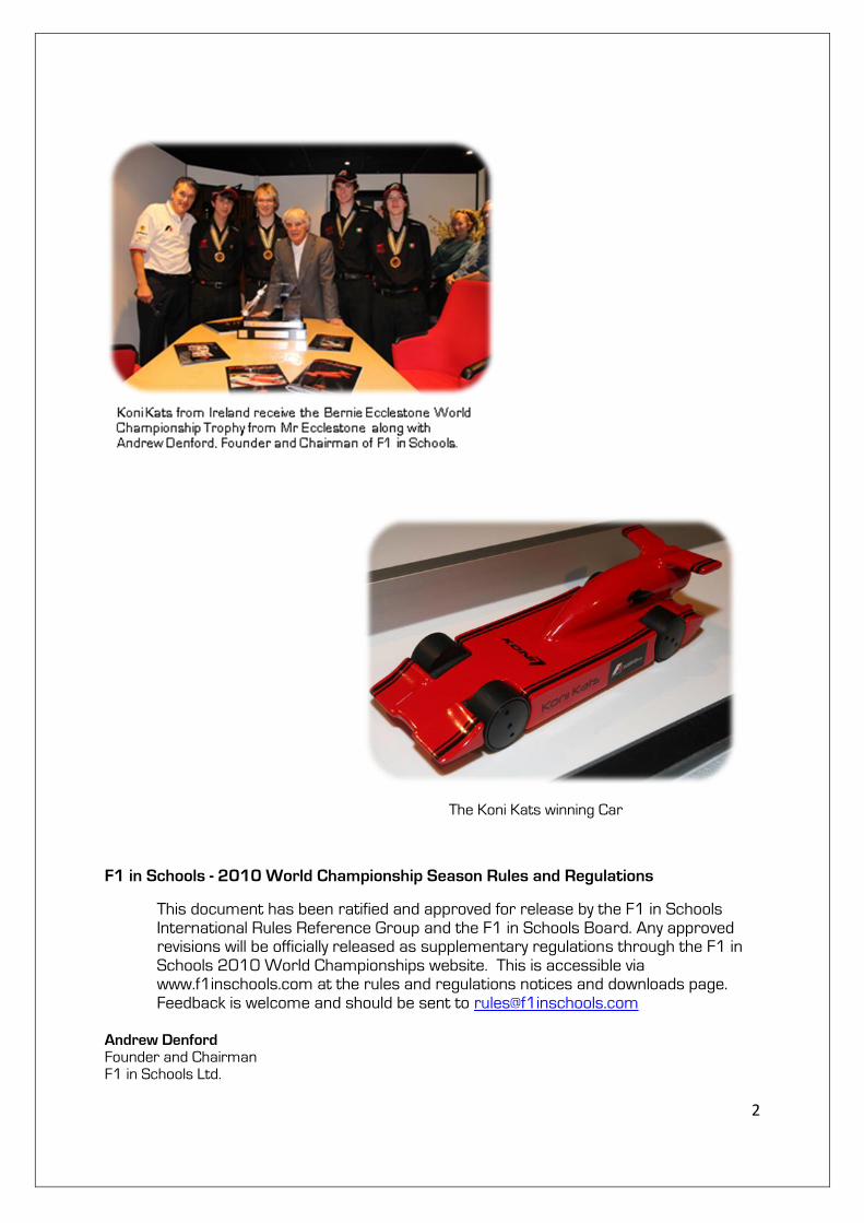
The Koni Kats winning Car
F1 in Schools - 2010 World Championship Season Rules and Regulations
This document has been ratified and approved for release by the F1 in Schools International Rules Reference Group and the F1 in Schools Board. Any approved revisions will be officially released as supplementary regulations through the F1 in Schools 2010 World Championships website. This is accessible via www.f1inschools.com at the rules and regulations notices and downloads page. Feedback is welcome and should be sent to [email protected]
Andrew Denford Founder and Chairman F1 in Schools Ltd.
3
What is the F1 in Schools Technology Challenge?
The F1 in Schools Technology Challenge is a competition, open to all secondary schools, sixth form colleges, colleges of further education and other organised youth groups to design and manufacture CO2 powered model racing cars. Student teams will compete against each other at the World Championships to determine the best engineered and fastest car in the world!
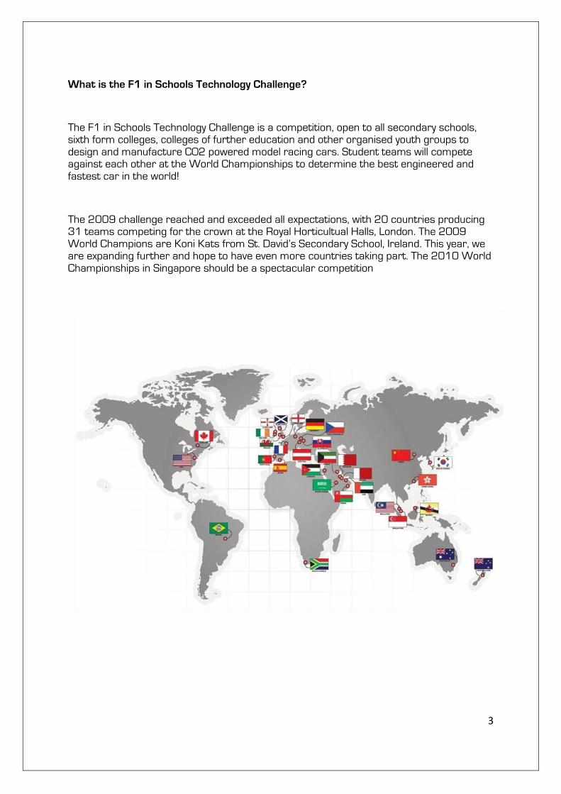
The 2009 challenge reached and exceeded all expectations, with 20 countries producing 31 teams competing for the crown at the Royal Horticultual Halls, London. The 2009 World Champions are Koni Kats from St. David’s Secondary School, Ireland. This year, we are expanding further and hope to have even more countries taking part. The 2010 World Championships in Singapore should be a spectacular competition
4
Why was the F1 in Schools Technology Challenge introduced?
The F1 in Schools Technology Challenge exists to raise the profile of engineering across schools and colleges around the world. CAD/CAM, CNC and VR systems are now common place in the manufacturing industry, which is why it is so important for the engineers and designers of the future to get to grips with it early on. Students using CAD/CAM, CNC and VR software are able to design, test, analyse and manufacture their own creations using the very latest technology.
Primarily, F1 in Schools provides students with an ideal opportunity to experience the very latest developments in manufacturing technology:
• CAD (Computer Aided Design) encourages students to think, explore and visualise their ideas in three-dimensions, using features such as complex curve modelling and surface rendering, alongside more traditional orthographic presentations.
• CAM (Computer Aided Manufacturing) packages, create an environment where CAD designs can
be developed and prepared for automated manufacturing processes. Some CAM Packages, such as Denford’s QuickCAM PRO, are wizard based and can be used to create tool paths for machining 3D parts on a Router.
• CFD (Computational Fluid Dynamics) packages, such as F1 VWT (Virtual Reality Wind Tunnel) allow computer models of car designs to be analysed, with regard to aerodynamic efficiency, then modified to further increase performance.
• VR (Virtual Reality) packages allow complicated machining and processing tasks to be practised in
real time and total safety. Packages allow CNC machining to be experienced, even when you don’t actually own the real CNC hardware!
• Video Conferencing systems allow students to solve problems in live conferences with experienced professionals, share and develop files on-line and visit manufacturing centres without having to leave their classroom.
• CNC (Computer Numerically Controlled) Machines, such as the Denford range of Routers, allow processed CAD drawings to be manufactured to high degrees of accuracy, fit and finish.
Through direct experience of the technology and processes required to complete this project, it is hoped that more students will be encouraged to explore and/or pursue a career in our design, engineering and manufacturing industries.
5
How to obtain Software, Hardware and Consumables
Your in-country co-ordinator should be able to help you. For their contact details visit www.f1inschools.com
Manufacturing Centres, Test Centres and Race Centres
Your in-country co-ordinator should be able to help you. For their contact details visit
www.f1inschools.com
Awards and Prizes
2010 WORLD CHAMPIONSHIPS - Open to 11-19 year old students.
FIRST PLACE - THE BERNIE ECCLESTONE F1 IN SCHOOLS WORLD CHAMPIONSHIP TROPHY
This will be awarded to the team with the highest total points scored. If there is a draw on points for the Championship, then the team with the best time trial will win.
There are also separate awards/prizes for:
• 2nd Place Overall
3rd Place Overall
• Fastest Car
• Best Engineered Car*
• Best Team Sponsorship & Marketing*
• Innovative Thinking Award
• Best Team Identity*
• The Collaboration Award (Please note: collaboration teams are now eligible for the World Championship Trophy)
• Outstanding Sportsmanship Award*
• Perseverance in the Face of Adversity*
• Best Newcomer (Team from a Country taking part in the World Championships for the 1st time)
• Best Pit Display*
• Best Verbal Presentation*
• Best Team Portfolio*
Note - * The above Awards are at the discretion of the Judges.
6
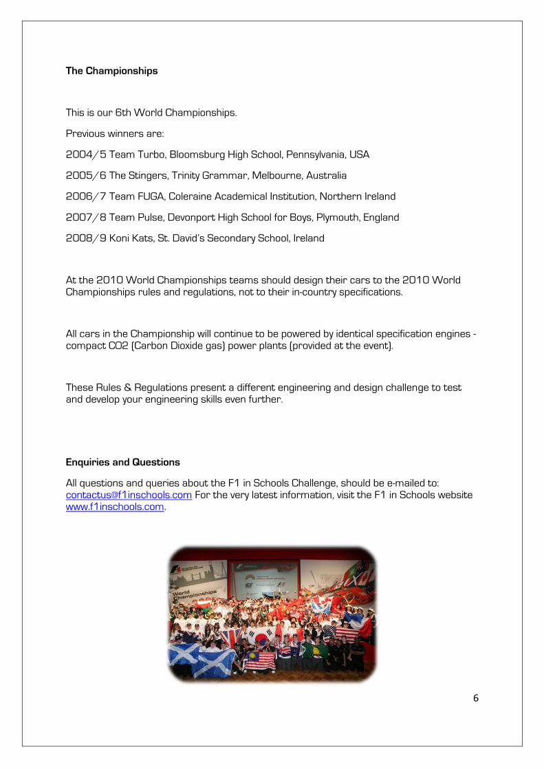
The Championships
This is our 6th World Championships.
Previous winners are:
2004/5 Team Turbo, Bloomsburg High School, Pennsylvania, USA
2005/6 The Stingers, Trinity Grammar, Melbourne, Australia
2006/7 Team FUGA, Coleraine Academical Institution, Northern Ireland
2007/8 Team Pulse, Devonport High School for Boys, Plymouth, England
2::8/9 Koni Kats, St. David’s Secondary School, Ireland
At the 2010 World Championships teams should design their cars to the 2010 World Championships rules and regulations, not to their in-country specifications.
All cars in the Championship will continue to be powered by identical specification engines - compact CO2 (Carbon Dioxide gas) power plants (provided at the event).
These Rules & Regulations present a different engineering and design challenge to test and develop your engineering skills even further.
Enquiries and Questions
All questions and queries about the F1 in Schools Challenge, should be e-mailed to: [email protected] For the very latest information, visit the F1 in Schools website www.f1inschools.com.
7
The Brief
You are the Formula One Team commissioned to design, construct and race the fastest Formula One Car of the Future, driven by compact compressed reclaimed CO2
(carbon dioxide gas) power plants. In order to enter the Championship, you must allocate job roles to the members of your group.
Ideally, one role should be allocated to each person. However, you may have to double up on your role and responsibilities, depending on the number of people you have available.
The following job roles, are examples of what could be covered by the members of your team:
• Team Manager (maximum 1 person).
This person could be responsible for managing the team, ensuring that the primary and back-up cars are ready for the finals. The team manager works closely with all members of the team, offering assistance where necessary.
• Resources Manager
This person organises time, materials and equipment for design and making the cars. They could be responsible for developing ideas regarding team marketing (presentation). The resources manager will need to liaise with all members to check tasks are progressing on time and offer additional help, if needed.
• Manufacturing Engineer
These people could be responsible for advising team members on the manufacture of the car and the constraints of the machining process. Manufacturing engineers will need to liaise with the design engineers to report and help solve any problems with construction of the car.
• Design Engineer
This role could be responsible for the styling and aerodynamic performance of the car design. Design engineers will need to liaise with the manufacturing engineers to ensure their ideas can be realised.
8
• Graphic Designer
This person could be responsible for producing the colour schemes applied to the vehicle, including any special sponsorship decals, together with the final graphic renderings and any additional team marketing materials. The graphic designer will need to liaise with the design engineer to ensure any schemes will fit the shape of the vehicle and the resources manager for additional marketing development.
There are so many tasks that must be mastered, in order to design, manufacture, prepare and finally enter a car for racing, that teamwork will be vital to your success. A real F1 team succeeds because all the people learn to work together and support each other.
Remember, no one person is more important than another.
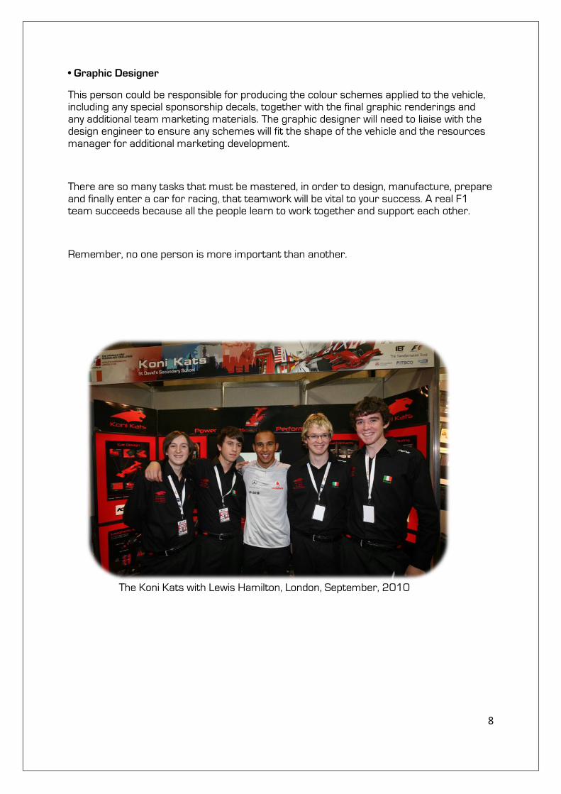
The Koni Kats with Lewis Hamilton, London, September, 2010
9
World Championship Criteria
Your team must comply with all the guidelines outlined below:
• Your team must contain a minimum of 3 to a maximum of 6 students.
• Each team must be invited to attend the World Championships by their in-country co-ordinator.
• Your team must use CAD (Computer Aided Design) software to produce your ideas and model them in 3D.
• Your team must use a CNC machine, such as a Denford Router, or an F1 in Schools approved Manufacturing Centre to produce the car body.
• Each car body must be manufactured either at your school/college or at a designated manufacturing centre/partner.
• Each car body must be completed with a high quality painted finish. Note that only a limited amount of hand finishing to the body is allowed.
• Each team must bring three identical cars to any race event - a primary race car, an identical spare back-up and a third promotional car, for F1 in Schools to keep.
• Each team must produce a design folder including initial ideas, design development and
evidence of testing - maximum 20 pages (A3 size) - see marketing criteria for further explanation on how the design portfolio will be assessed.
Please note: 20 pages includes front and back pages. Portfolio can be 20 single sided or 10 double sided pages.
• F1 teams are encouraged to develop partnerships and seek assistance from businesses and industry throughout this engineering process. However, all aspects of this engineering and industry partnership should be represented in the team’s portfolio. This includes CAD designs, painting of the cars, and the creation/production of the portfolio, which should remain the responsibility of the students in the team
10
• Each team must supply (in the design folder) a dimensioned 3rd angle orthographic projection and a graphic rendering of their final design, both produced using a 3D CAD package.
• Each team must complete a specification sheet, as supplied by the Event Co-ordinators, which must be submitted at each race event.
• Teams must prepare and deliver an 8 minute verbal presentation on their work.
Suggested content:
How the team has performed.
Innovation
As a team and individuals, how have you benefited from the F1 in Schools experience / what have you learnt /how has it changed your life
Decision on job roles/teamwork
Explanation on each area of the challenge. (Design, Analyse, Make, Test & Race)
How was the design agreed upon.
Software used.
Engineering the car.
Uniqueness of the team.
Collaboration with industry/higher education.
Aerodynamics of the car.
Manufacturing skills addressed.
(See marking criteria for further explanation on how the verbal presentation will be assessed.)
11
Design Considerations
Design Preparation:
Before beginning to design your car, you will need:
• A 3D CAD solid modelling software package at your school/college.
• A design template suitable for the balsa wood blank.
• Hopefully, an endless supply of ideas!
Training:
CAD packages will help you draw and develop your ideas in 3D. Of course, as with most drawing packages, it takes time to learn how to use them.
Your technology teacher should be able to show you how the software works, but members of your team will need to spend some time exploring the software, so you can see what it can do and how it can help you design your F1 car.
Research:
Investigate existing F1 car designs. Your teacher may be able to help you use the internet to find out the latest developments occurring in the world of F1 design. Concentrate your research on areas that could help your team, for example, aerodynamics and car body designs, then try to apply the principles to your own ideas.
Testing:
Your team may want to consider testing a variety of car designs, or car parts, in a wind and/or smoke tunnel to evaluate their aerodynamic performance.
12
Manufacturing Considerations
In the F1 Car Kit you will receive a balsa wood block, a set of 4 wheels, 2 axles and some glass paper, which is the minimum that you need to enter the challenge.
Note that your car design template must be at least 10mm shorter at one end, compared to the actual balsa wood block (we have accounted for this is in the Rules & Regulations, point 2a). You will not be able to machine to the extreme ends of the balsa wood block, since they are sometimes used for attaching the CNC machine fixtures. Damage could occur if the cutting tool hits any of these fixtures.
The fixture is used to stop the balsa wood block moving whilst being machined. It also allows the block to be accurately repositioned.
Please note however that some machines will process with only one cut, others may require two or more cuts and therefore you will need to take this into account when you are designing the car.
Once machined, you can smooth down the balsa wood design and finish with primer and paint.
Note that only a limited amount of hand finishing to the body is allowed. You could also decorate the car body with any sponsorship stickers, advertising or colour schemes.
13
1. General Regulations
Please refer to Rules Compliance Drawing.
1a. All cars must be designed using a CAD/CAM package. This package must satisfy all the challenge entry criteria and allow students to produce a 3D graphic rendering and 3rd angle orthographic projection. The CAM package should allow students to simulate CNC processes so students can show evidence of the process in their portfolio. We recommend the use of Denford’s QuickCAM 3D software. Your F1 car must be manufactured on a CNC machine, such as a Denford Micro Router, either at your school/college or at an F1 in Schools approved Manufacturing Centre.
1b. All cars must be designed considering the specified dimensions and regulations. Only a limited amount of hand finishing is allowed, e.g. removal of machining scallops. All cars should be complete and finish painted to a high standard.
1c. World Championship Teams will be the overall winner of the in-country National Final or by special invitation. Invitations will be distributed by in-country co-ordinators and ratified by F1 in Schools Ltd. Therefore entry is by INVITATION ONLY.
1d. Each team must consist of a minimum of 3 members to a maximum of 6. Mixed gender teams are preferred and positively encouraged. Collaboration teams must consist of a minimum of 4 members up to a maximum of 6 with a minimum of 2 members from any country i.e. 3 countries as a maximum
1e. Each team must provide three (3) identical cars at the World Championships. One nominated as the race car, one nominated as the back-up car and one nominated for being retained by F1 in Schools for promotional purposes.
1f. Each car design must leave enough space on the side pods for the official F1 in Schools
logo decal. The logo sticker will be supplied upon registration and must be adhered before racing. Refer to Reg. 2c for decal placement and size.
1g. Each team must produce a design portfolio of work including initial ideas, design development, manufacturing and evidence of testing. There should also be evidence of CAM and CNC within the portfolio. These should be presented in an A3 (or similar) sized format and displayed in the “Pits”. Refer to World Championships Marking Criteria to see the required folio content that will be assessed by the judges.
The organisers require this to be submitted two weeks prior to the event for pre-judging and your ICC's will advise you of the date and address ASAP. Please note, only the first 20 sheets (or 10 double sided sheets) of the portfolio will be marked - (including the cover sheets).
1h. A 3rd angle orthographic projection, including plan, side and end elevations, along with a 3D rendering must be included in the portfolio, both produced using a CAD package. The orthographic should include detailed dimensions to illustrate regulation requirements.
1i. The official length of the track, from start to finish, is 20 metres. The tether line diameter is 0.57mm,
1j. All cars will be checked for safety and that the screw eyes /plastic inserts are secure. If the Judges/Marshalls are unhappy with the safety of the vehicle or a rule infringement
14
has occurred, teams can submit their spare car. Otherwise the team may be disqualified or points deducted from the overall team score.
1k. Judging will assess areas such as aerodynamics, engineering, aesthetics, quality and accuracy of manufacture, race times and team presentation. Please refer to the marking criteria. Overall winners will be determined by combining point scores from each category in the challenge.
PLEASE NOTE: THE JUDGES DECISION IS FINAL.
1l. Cars will be handed into race control and held in ‘parc ferme’ for the duration of the event. (Cars can only be released from ‘parc ferme’ with the Chair of Judges permission).
1m. Teams will be required to deliver a verbal presentation about their project to the Judges. The presentation must not last longer than 8 minutes. If teams are unable to deliver the presentation in English, then an interpreter can be present and a time of 16 minutes will be allocated.
1n. Tolerances for all specifications.
Dimension tolerance is +/- 0.1mm.
Weight tolerance is +/- 0.5grams.
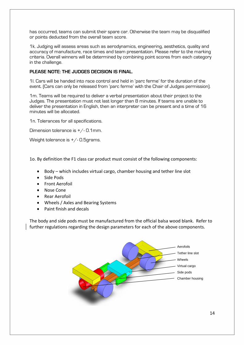
1o. By definition the F1 class car product must consist of the following components:
Body – which includes virtual cargo, chamber housing and tether line slot
Side Pods
Front Aerofoil
Nose Cone
Rear Aerofoil
Wheels / Axles and Bearing Systems
Paint finish and decals The body and side pods must be manufactured from the official balsa wood blank. Refer to further regulations regarding the design parameters for each of the above components.
Aerofoils
Tether line slot
Wheels
Virtual cargo
Side pods
Chamber housing
15
1p. Race cylinders will be kept in a climate controlled environment to ensure all the
temperatures are the same - all cylinders will be weighed and will be within +/- 0.25gm of
each other.
2. Body and Side Pod Regulations
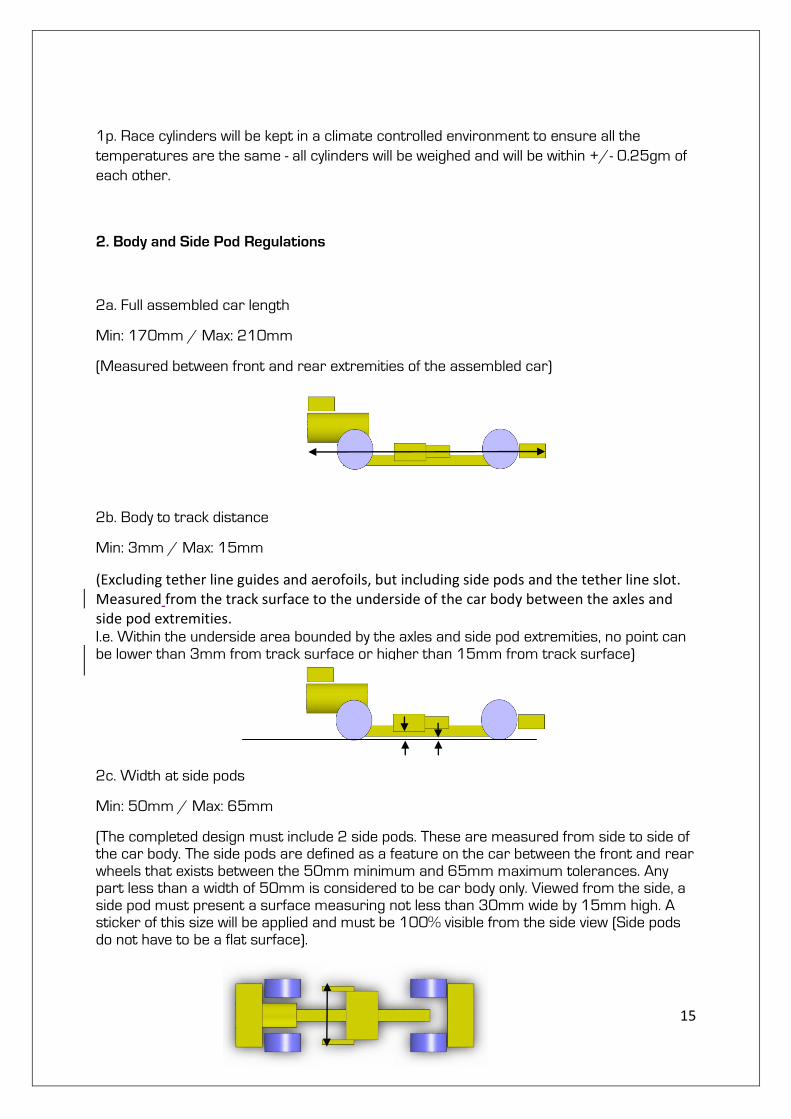
2a. Full assembled car length
Min: 170mm / Max: 210mm
(Measured between front and rear extremities of the assembled car)
2b. Body to track distance
Min: 3mm / Max: 15mm
(Excluding tether line guides and aerofoils, but including side pods and the tether line slot. Measured from the track surface to the underside of the car body between the axles and side pod extremities. I.e. Within the underside area bounded by the axles and side pod extremities, no point can be lower than 3mm from track surface or higher than 15mm from track surface)
2c. Width at side pods
Min: 50mm / Max: 65mm
(The completed design must include 2 side pods. These are measured from side to side of the car body. The side pods are defined as a feature on the car between the front and rear wheels that exists between the 50mm minimum and 65mm maximum tolerances. Any part less than a width of 50mm is considered to be car body only. Viewed from the side, a side pod must present a surface measuring not less than 30mm wide by 15mm high. A sticker of this size will be applied and must be 100% visible from the side view (Side pods do not have to be a flat surface).
16
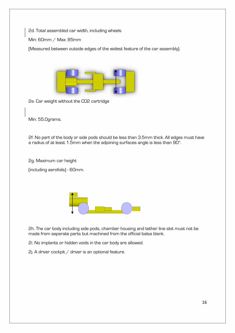
2d. Total assembled car width, including wheels
Min: 60mm / Max: 85mm
(Measured between outside edges of the widest feature of the car assembly).
2e. Car weight without the CO2 cartridge
Min: 55.0grams.
2f. No part of the body or side pods should be less than 3.5mm thick. All edges must have a radius of at least 1.5mm when the adjoining surfaces angle is less than 90°.
2g. Maximum car height
(including aerofoils) - 60mm.
2h. The car body including side pods, chamber housing and tether line slot must not be made from separate parts but machined from the official balsa blank.
2i. No implants or hidden voids in the car body are allowed.
2j. A driver cockpit / driver is an optional feature.
17
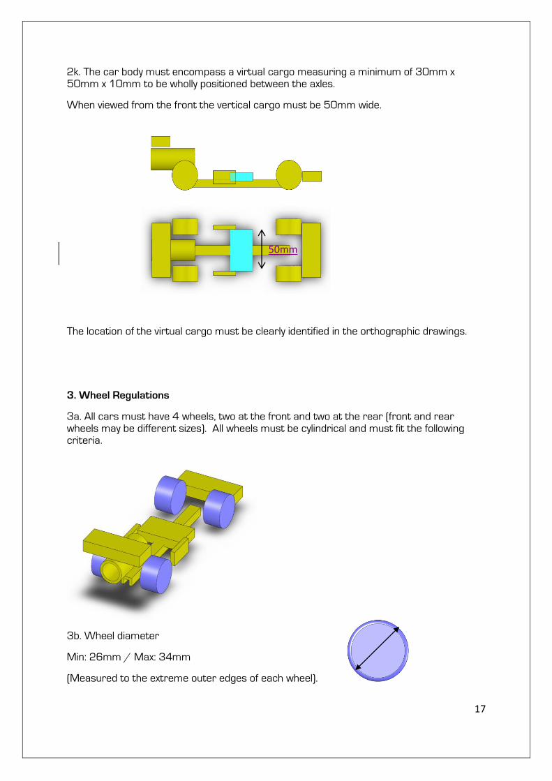
2k. The car body must encompass a virtual cargo measuring a minimum of 30mm x 50mm x 10mm to be wholly positioned between the axles.
When viewed from the front the vertical cargo must be 50mm wide.
The location of the virtual cargo must be clearly identified in the orthographic drawings.
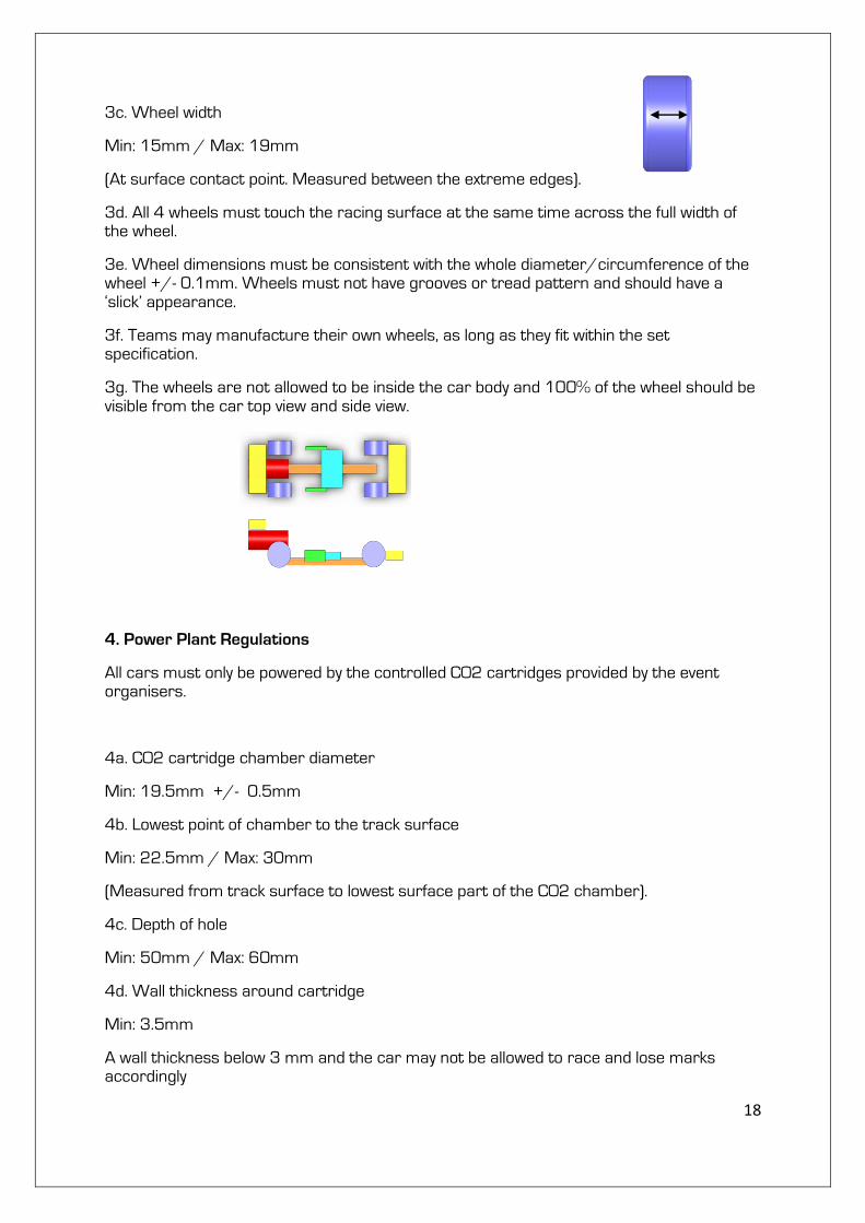
3. Wheel Regulations
3a. All cars must have 4 wheels, two at the front and two at the rear (front and rear wheels may be different sizes). All wheels must be cylindrical and must fit the following criteria.
3b. Wheel diameter
Min: 26mm / Max: 34mm
(Measured to the extreme outer edges of each wheel).
50mm
18
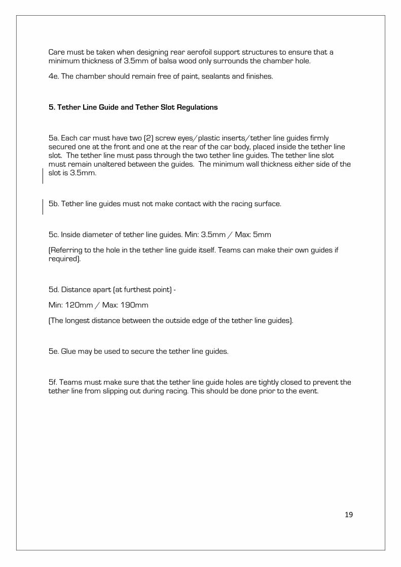
3c. Wheel width
Min: 15mm / Max: 19mm
(At surface contact point. Measured between the extreme edges).
3d. All 4 wheels must touch the racing surface at the same time across the full width of the wheel.
3e. Wheel dimensions must be consistent with the whole diameter/circumference of the wheel +/- 0.1mm. Wheels must not have grooves or tread pattern and should have a ‘slick’ appearance.
3f. Teams may manufacture their own wheels, as long as they fit within the set specification.
3g. The wheels are not allowed to be inside the car body and 100% of the wheel should be visible from the car top view and side view.
4. Power Plant Regulations
All cars must only be powered by the controlled CO2 cartridges provided by the event organisers.
4a. CO2 cartridge chamber diameter
Min: 19.5mm +/- 0.5mm
4b. Lowest point of chamber to the track surface
Min: 22.5mm / Max: 30mm
(Measured from track surface to lowest surface part of the CO2 chamber).
4c. Depth of hole
Min: 50mm / Max: 60mm
4d. Wall thickness around cartridge
Min: 3.5mm
A wall thickness below 3 mm and the car may not be allowed to race and lose marks accordingly
19
Care must be taken when designing rear aerofoil support structures to ensure that a minimum thickness of 3.5mm of balsa wood only surrounds the chamber hole.
4e. The chamber should remain free of paint, sealants and finishes.
5. Tether Line Guide and Tether Slot Regulations
5a. Each car must have two (2) screw eyes/plastic inserts/tether line guides firmly secured one at the front and one at the rear of the car body, placed inside the tether line slot. The tether line must pass through the two tether line guides. The tether line slot must remain unaltered between the guides. The minimum wall thickness either side of the slot is 3.5mm.
5b. Tether line guides must not make contact with the racing surface.
5c. Inside diameter of tether line guides. Min: 3.5mm / Max: 5mm
(Referring to the hole in the tether line guide itself. Teams can make their own guides if required).
5d. Distance apart (at furthest point) -
Min: 120mm / Max: 190mm
(The longest distance between the outside edge of the tether line guides).
5e. Glue may be used to secure the tether line guides.
5f. Teams must make sure that the tether line guide holes are tightly closed to prevent the tether line from slipping out during racing. This should be done prior to the event.
20
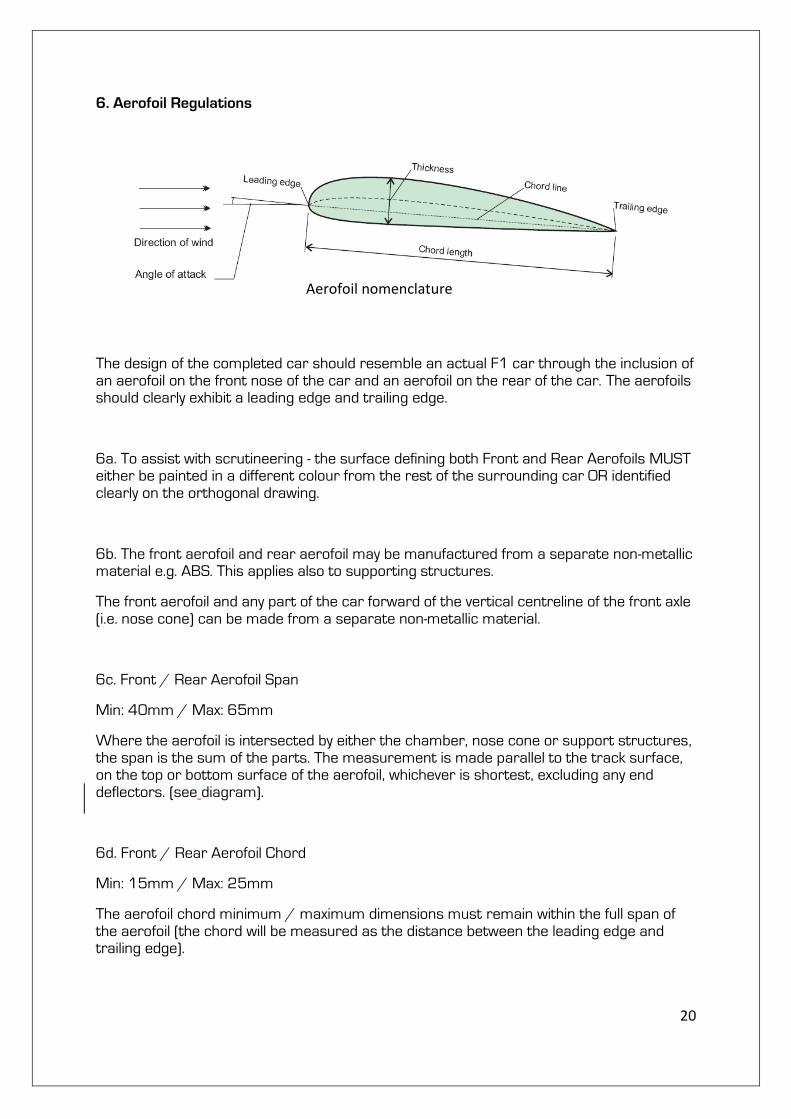
6. Aerofoil Regulations
The design of the completed car should resemble an actual F1 car through the inclusion of an aerofoil on the front nose of the car and an aerofoil on the rear of the car. The aerofoils should clearly exhibit a leading edge and trailing edge.
6a. To assist with scrutineering - the surface defining both Front and Rear Aerofoils MUST either be painted in a different colour from the rest of the surrounding car OR identified clearly on the orthogonal drawing.
6b. The front aerofoil and rear aerofoil may be manufactured from a separate non-metallic material e.g. ABS. This applies also to supporting structures.
The front aerofoil and any part of the car forward of the vertical centreline of the front axle (i.e. nose cone) can be made from a separate non-metallic material.
6c. Front / Rear Aerofoil Span
Min: 40mm / Max: 65mm
Where the aerofoil is intersected by either the chamber, nose cone or support structures, the span is the sum of the parts. The measurement is made parallel to the track surface, on the top or bottom surface of the aerofoil, whichever is shortest, excluding any end deflectors. (see diagram).
6d. Front / Rear Aerofoil Chord
Min: 15mm / Max: 25mm
The aerofoil chord minimum / maximum dimensions must remain within the full span of the aerofoil (the chord will be measured as the distance between the leading edge and trailing edge).
Aerofoil nomenclature
21
6e. Front / Rear Aerofoil Thickness
Min: 1.5mm / Max: 6mm
The aerofoil thickness minimum / maximum dimensions must remain across the full span of the aerofoil (the thickness will be measured perpendicular to the chord line).
6f. Aerofoils may be adjustable in design however they must be fixed whilst in competition.
Please note: Balsa wood aerofoils below 3mm thick will be more susceptible to breakage.
6g. The whole of the Front Aerofoil including support structures when viewed from the side must be in front of the centre line of the front wheel.
6h. The whole of the Rear Aerofoil when viewed from the side must be behind the rear wheel.
6i. The bottom surface of the Rear Aerofoil must be higher than the highest point of the rear wheel when measured normal to the track surface.
7. Car Repair Regulations
7a. Teams WILL BE PERMITTED to carry out maintenance on cars in the official CAR SERVICE AREA. This will be allowed to occur only between automatic time trial and reaction time racing as per the event schedule.
7b. If an entry becomes damaged and the damage is determined by the officials to be related to engineering deficiencies, the car may be repaired or an identical back-up car used.
Any repair or change of car during racing for this reason will result in a single 5 point penalty. This penalty is applied against total points awarded for that race event category and can only be incurred once. If the officials determine the damage is not related to engineering deficiencies, repairs or replacement with an identical back-up car will be allowed without penalty.
7c. Damage incurred during a race, before the car crosses the finish line, (e.g. wheel, wing, screw eye or any other part of the car separating from the entry) will result in a DNF race result.
7d. All damage issues and related decisions are to be decided by the race track officials or scrutineers and referred to the Chair of Judges if necessary.

22
8. Grievances
Any grievance issues must be lodged by the team manager with the Chair of Judges by the date and time stated in the event supplementary regulations. All grievances must be lodged in writing via the official grievance form available from the Event Directors.
The Chair of Judges decision related to any grievance is final.
9. Race Regulations
9a. Race Procedures
At the 2010 World Championships there will be 3 types of races conducted.
1. Time Trails (Automatic Launch Mode)
2. Reaction Time Racing (Manual / Driver Launch Mode)
3. Knock-out Competition Racing (Manual / Driver Launch Mode)
Teams will be allowed to advise the start marshalls on any special procedures to their car on the track in positioning and to set the deceleration towels prior to each race.
9b. Time Trails
These will be conducted over the course of the Competition Days as per the judging schedule. Team members need to be at the race track during their scheduled race times. Each car will be raced at least twice in each lane of the race track. The single fastest time recorded by each team during racing (Time Trials and Reaction Time Racing) will be used to determine the marks they are awarded for time trails.
9c. Reaction Time Racing
These races will be conducted during the Competition Days as per the judging schedule. ALL team members need to be at the race track during their scheduled time. “Drivers” will not be allowed to practice during this official race time. Reaction practice will be allowed at other times on the public race track. Each car will be raced at least once in each lane. The single fastest total race time recorded (reaction time PLUS actual car start line to finish line time), by each team will be used to determine the marks they are awarded for Reaction Time Racing. At the conclusion of Reaction Time Racing, all teams will be ranked from fastest to slowest to determine each team’s Knock-Out Racing seeded position.
9d. Knock-out Competition These races will be conducted during the Competition Days as per the event schedule. Ranking from Reaction Time Racing results will determine where teams start in the knock-out rounds. ALL team members need to be at the race track

23
during their scheduled times. All teams will receive a detailed schedule and confirmed knock-out draw. Each car will be raced (manual /driver launch mode), once in each lane. The single fastest time posted from these 2 races (reaction time PLUS actual car start line to finish line time), will determine the winner for that knock-out race and advance to the next knock-out round.
NB. Marks will be included within the marking criteria document.