Embed Size (px)
Citation preview
THRO~JGH THE INITIATIVE OF MAYOR REPITO PAJARILLO LO ANL) THE SANGGUNIIANG BAYAIV Of: MERCEDES
E1992v3
Pub
lic D
iscl
osur
e A
utho
rized
Pub
lic D
iscl
osur
e A
utho
rized
Pub
lic D
iscl
osur
e A
utho
rized
Pub
lic D
iscl
osur
e A
utho
rized
Pub
lic D
iscl
osur
e A
utho
rized
Pub
lic D
iscl
osur
e A
utho
rized
Pub
lic D
iscl
osur
e A
utho
rized
Pub
lic D
iscl
osur
e A
utho
rized
The site was initially visited on 26 Septernbcr 2003 aid then severa!
reconnaissance trips and detailed surveys were untiertaken lasting up to 15
Novernber 2003.
1.4 PROJECT LOCATION AND RELATIVE DISTANCES
1.4.1 General
The Colasi river, where a proposed mini-hydro power systern will be
situated, is located about forty (40) kilometers southeast (SE) of Daet,
the capitol town of the Province of Camarines Norte. Figure 1-1
shows the location map.
1.4.2 Specific Eocation of Primary Scheme
The proposed project site is located w i t b the political b o u n d q of
Mercedes Municipality. The proposed diversion dam is situated at 13'
55' 12' latitude and 123" 03' 04' longitude. Similarly, the power plant
site is located at 13' 03' 37' latitude and 123" 50' 49' longitude
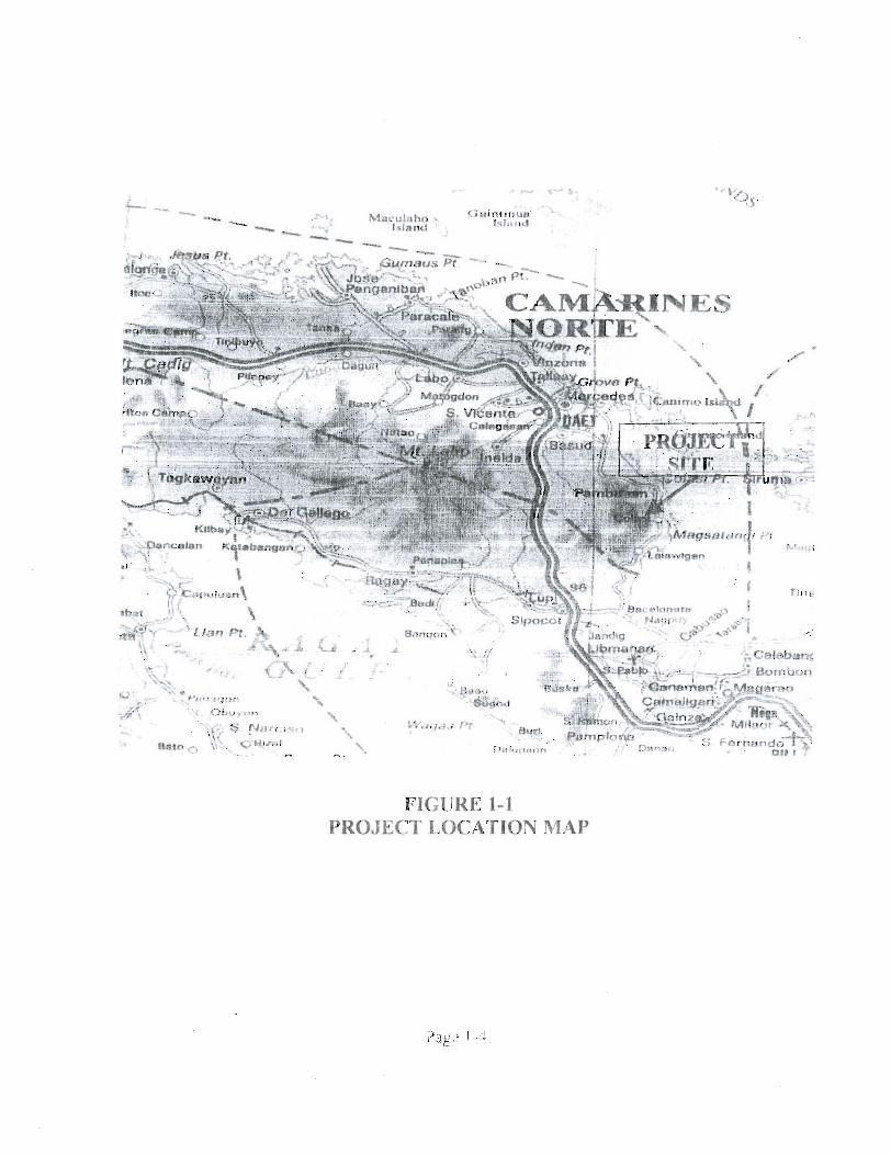
FIGURE 1-1 PROJECT LOCATION MAP
CHAPTER 4.0: WATER RESOURCES
4.1 WATER SOURCE DESCRIPTION
The mini-hydro site is located at the upper reaches of the Colasi river
draining the west-east slope of Colasi mountains.
The mini-hydro site is situated on a mountainous area. The watershed cover
consisting of relatively thick second growth forest trees and undergrowtfis is
classified as generally in good hydrologic condition. Srnail expanses of
relatively flat grounds are pianted to upland rice, com and vegetab1es. The
river and tributary system is classified under youthful development stage.
The channels are characterized with tlie presence of deep v-shaped valleys,
steep slopes, rapids and waterfalls.
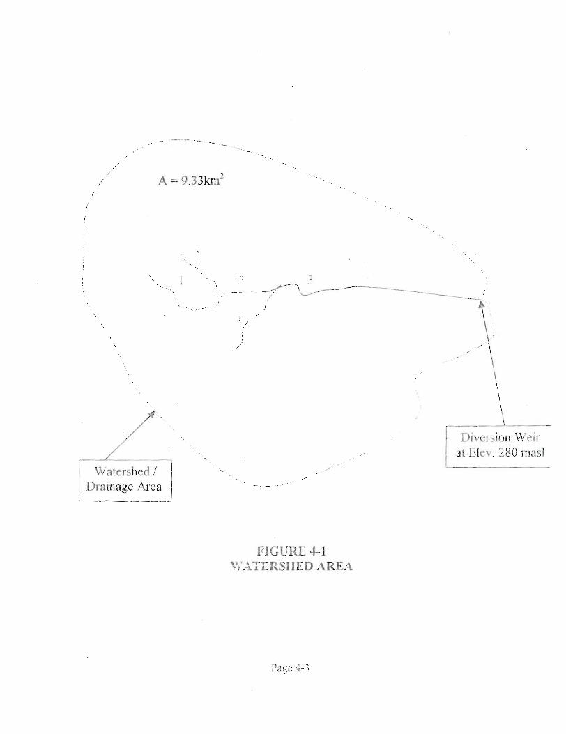
The delineation of the watershed area is shown figure 4-1 based on a best
weir location of Elev. 280 rneters (rn) above mean sea level. On the bas~s .of
this level, the calculated drainage area is:
WATERSHED AREA = 9.3 Km2
Page 4- 1

4.2 hlYDRQMETEOROLBGICAL CHARACTETUSTICS
The area falls under type II climate. This climate type is characterized by no
district seasons with very pronounced maximwn rainfall fkom October to
J a n u v and no dry season. Nomally under ths type, r d a l l is fairly well
distributed throughout the year
The following is a s m a q of climactic conditions at the projeçt site:
Area Climate Classification .............. Type I1 Normal Dry Periods.. ...................... No pronoimced dry season Normal Rainfall Period.. ................. Fairly distribiited yearly with
pronounced maxirnum ramfa11 fiom October to Jan.
Mean Maximum Rainfall (Dec.). ........ 598.8 mm. Mean Minimum Rainfall (March) ....... 147 mm. Mean Annual Ramfall ..................... 3 3 1 1 inm. Mean Annual Temperature ................ 27.1 0 "C Referente Data Records.. ................ PAGASA Weather Bureau
TGhe figures shown in subsequent pages fiirtl~er illustrate the
Iiydrometeorological characteristics of the project area. These are:
Figure 4-2 : Typical graph of type II climate for the entire Plclippines
Figure 4-3 : Mean Monthly and Annual Ramfall Depth
Figure 4-4 : Rainfall-Intensity-Freqiiency Duratioa Data tm F)
Page 4-2
- ', .- I
I C .
Diversioil W eir at Elev. 280 mas1 i
FIGURE 4-1 FTr,STERSIIED AREA
Pape 4-.?
CHAPTER OS: PLAN OF DEVELOPMENT
5.1 CIVIL WORKS SCNEMATIC
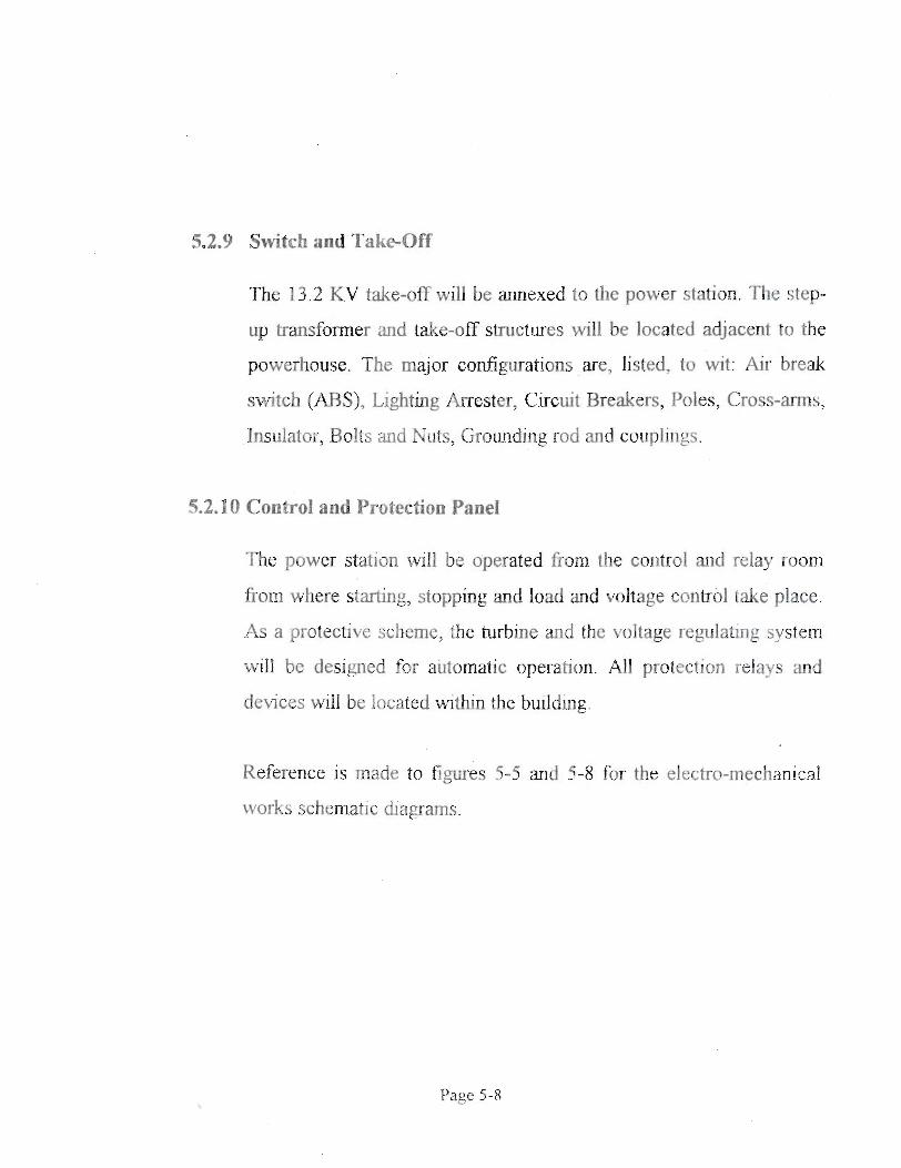
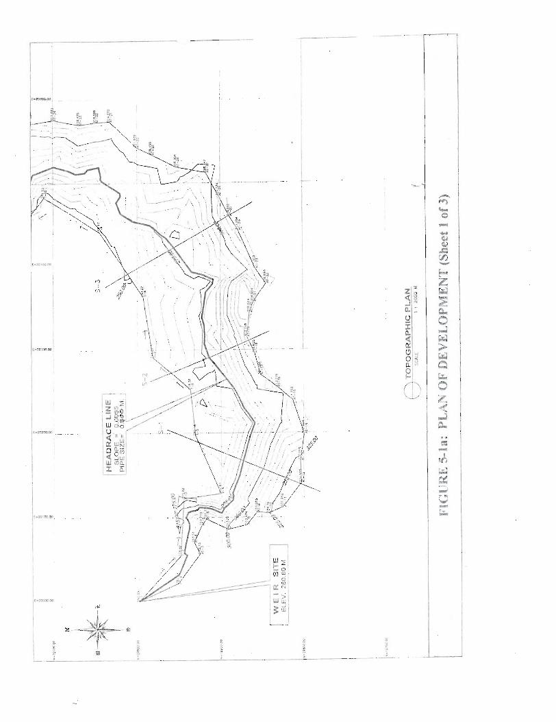
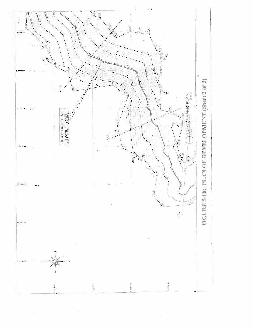
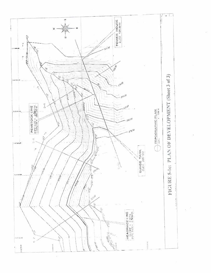
S. 1.1 General Plan of Development
Civil works consist of the constmction of the intake weir: headrace
canal, strge ta&, penstock, powerhotise, and aitxiliary siipport
stmctiires. The general plan of developrnent is shown in Figtrres 5- la
to 5-1 c. Based on the geological and water resoilrce considerations as
explained in the foregoing chapters, the proposed weir site is located
at El. 280.80 meters (rn) The proposed headrace rotite wiil be at the
1efi bank of the river (fookuíg tipstrem). The tailrace leve1 at the
proposed power pfant site was set at El. 125.00 based on the tailwater
sating c111-ve Additional details of the varioiis scheii-ic of the plant
instaifation are presented in the outltne drawings of Figures 5-2
through 5-8
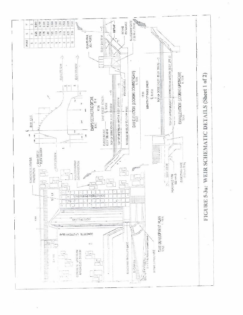
S. 1.2 Wcir Structure
The type of weir will be an ogee crest concrete overflow nin-off-the-
river type stnichire, hoiilder core with concrete binder and wearing
surface, complete with sluiceway, headrace, intake? hydraulic gates,
and other apprirtenant stnichires as show-~ in Figures 5-33 and 5-3h
Page 5 - 1
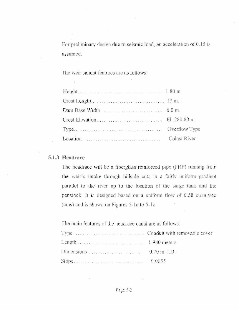
For preliminary design due to seisnuc load, an acceleration of 0.15 is
assumed .
The weir salient features are as follows:
Heigbt ..........
..... Crest Leligtla.
Dam Base Width.. . . .
Crest Elevation.. ........
T ype ...................
Location . . . .
.... 1.80 m.
........ 17 m.
.... 6.0 m.
El. 280.80 m.
... Overflow Type
Colasi River
5.1.3 Headrace
'The headrace wilI be a fiberglass reinforced pipe (FRP) ninning fiom
the weir's intake through hillside cuts in a fairly uniform gradient
parallel to the river up to the location of the surge tank and the
penstock. It is designed based on a d o m flow of 0.58 cu.m./sec
(cms) and is shown on Figures 5-1 a to 5-1 c.
'The rnain features of the headrace canal are as follows:
Tqpe . . . . . . . . . . . . . . Conduit with removable cover
. . . . . . . . . . Length . . . 1,980 metexs
Dimensions . . . Q.70 m. I.D.
. . . . . . . Slope 9.005 5
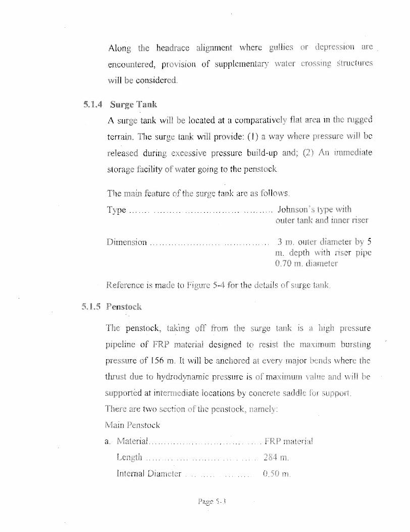
Along the headrace alignrnent where gullies or depressiori are
encountered, provisi011 of supplementary water crossing structures
will be considered.
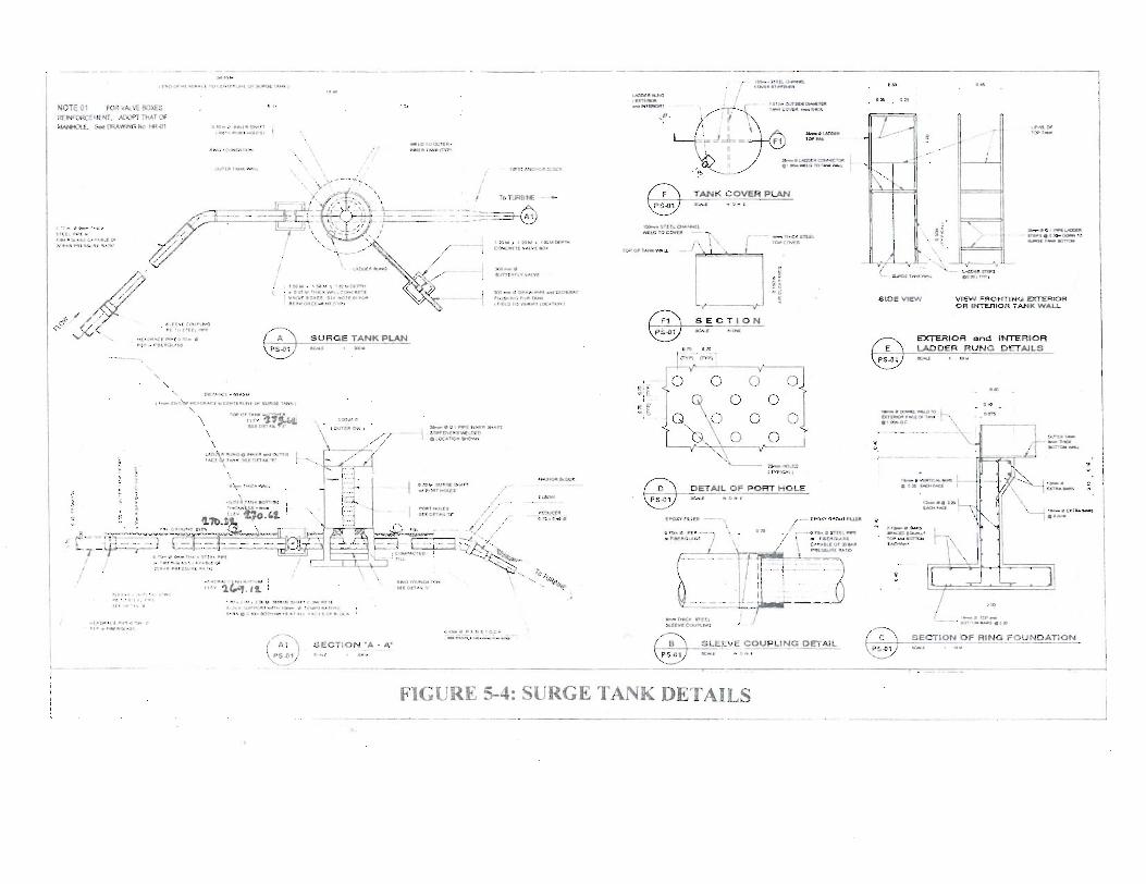
5A.4 Surge Tank
A surge tank will be located at a comparatively flat area in the rugged
terrain. The surge tank will provide: ( I ) a way where pressure will be
released during excessive pressure build-up and; (2) An immediate
storage facility of water going to the penstock
The main feature of the surge tank are as follows:
......... T ype ............................. Johnson's type with outer tank and inner riser
. . . . 3 m. outer diameter by 5 m. depth with riser pipe 0.70 m. diameter
Reference is made to Figure 5-4 for the details of surge tank
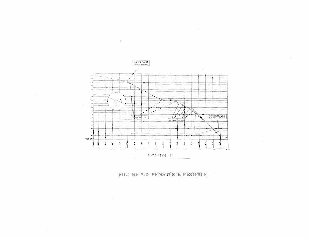
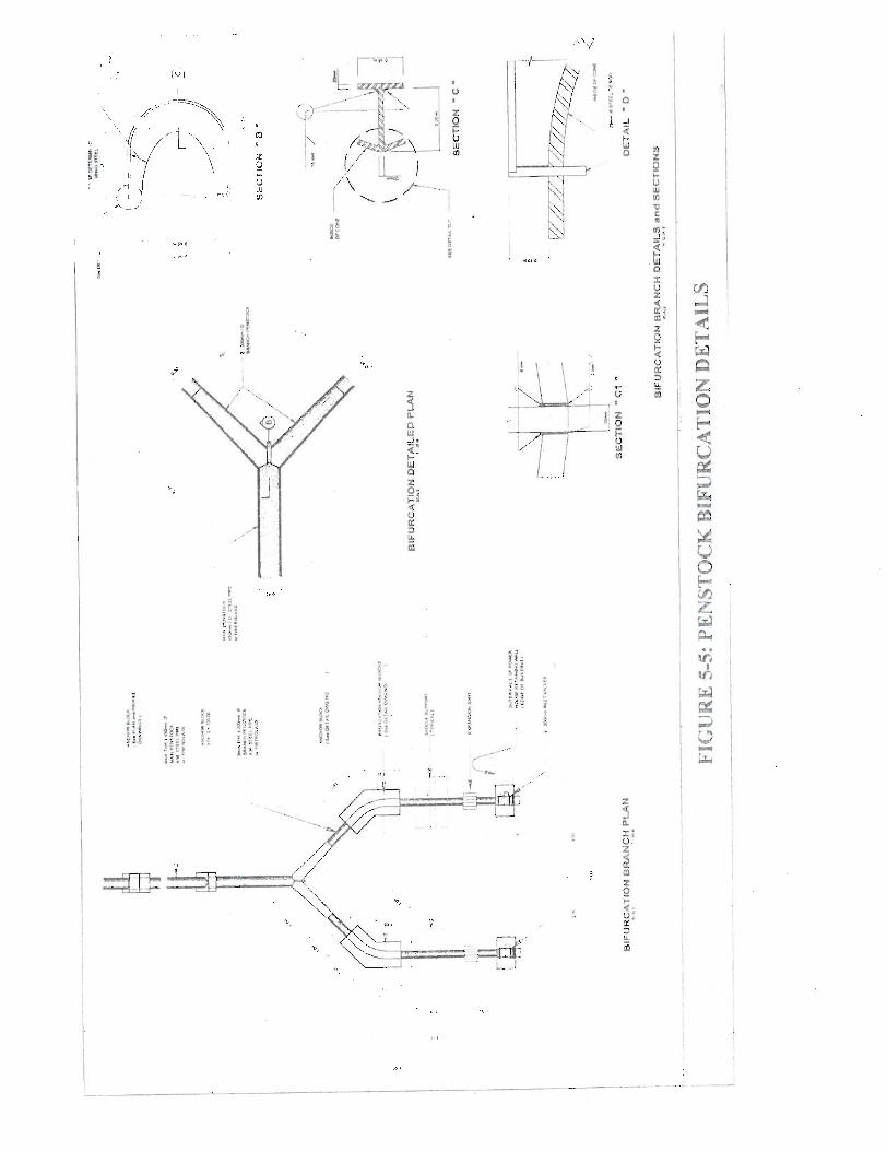
5.1.5 Penstock
The penstock, tak'ing off fiom the surge tank is a higb pressure
pipeline of FICP material designed to resist the rnaximum bwsting
pressure of 156 m. It will be anchored at every major bends where the
t h s t due to hydrodynamic pressure is of rnaximurn vaIiie and will De
supported at internediate locations by concrete saddte for support.
There are two sectron of the penstock, narnely
Main Penstock
a. Material .
Length .
Interna1 Diameter
. . . . . FRP material
. . . . 284 m.
0.50 m. . . .
b. Branch Penstock
Nurnber of Branches ...
Material ..............
Length per branch ......
Diameter per branch ...
1 . . . . L
....... FRP material
. . 10 m.
.. 0.30.m
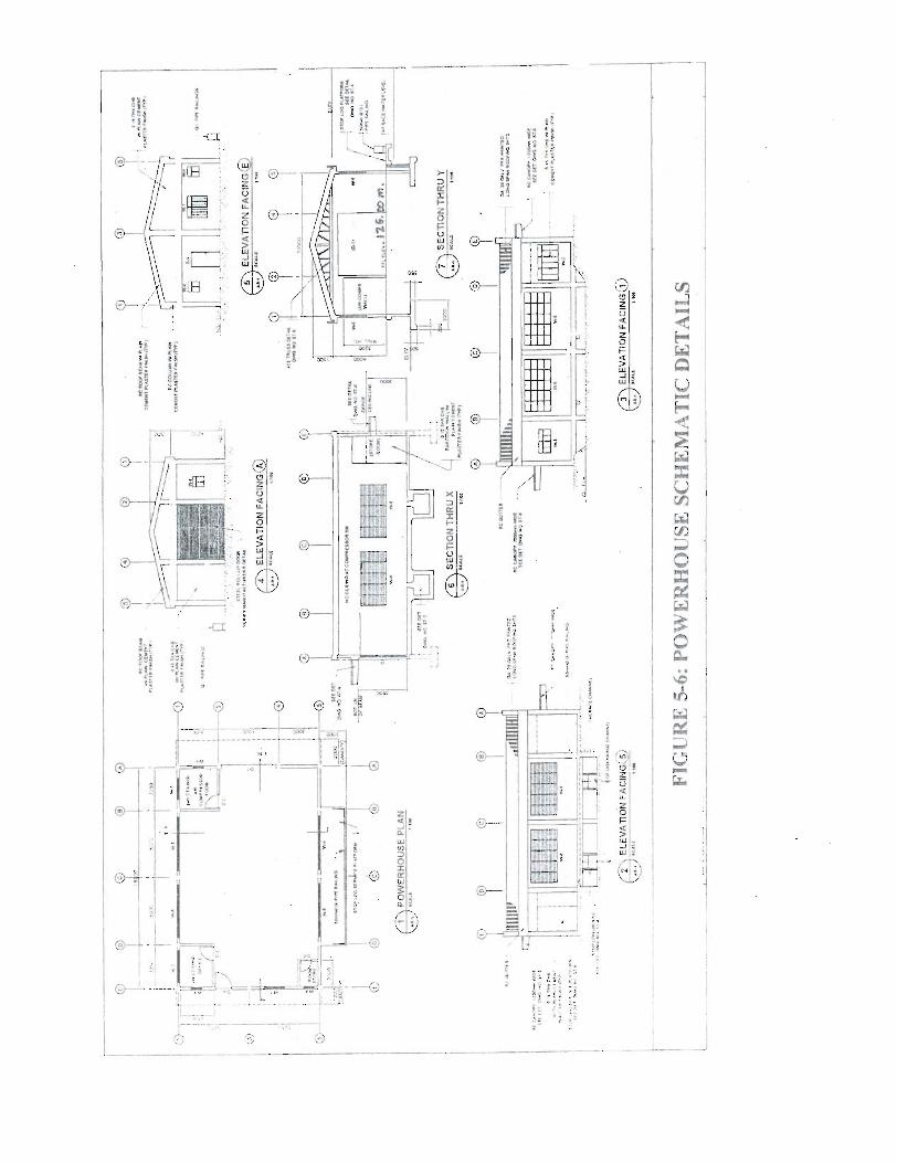
5.1.6 Powerhouse
Refening to Figure 5-6 shows the outline design of the powerhouse.
Gross floor dimension of powerhouse is 16.5 by 10.5 meters for a
floor area of 168 square meters (sq.m.1.
5.1.7 Service Road
An access road will be build from the existing barangay main road to
the plant site with distance of about 3 kilometers (km) include a 4.50-
meter travei way.
5.2 ELECTRO-MECHANICAL EQUlPMENT AND RELATED WORKS
5.2.1 General
The electro-mechanicai equipment and related works mainly covers
the generating equipment of tile plant including zppurteriant works
and distribution iines.
Paçe 5-4
5.2.2 Hydraulic Turbines
The proposed maxunurn turbùie discliarge of 0.29 crns. with a net
head of 140 m. will yield a maximurn turbine output of 330 KW. The
Pelton type of turbines are chosen for the given head/discharge
relation. To prevent damages to runner and distributors, these turbines
will nomally not be allowed to run below 40 percent of rnaximum
discliarge.
An optimization of power production and total costs has resulted in
the chosen installation of two (2) turbines with identical output of
330-KW each. For the two units, the turbine capàclty sums ta 640
KW. A summary on the data for the turbines are:
Type - Pelton Turbine Output - 320 KW Number of Units - 2 Gross Head - 155 m. Net design head - 140 in. Speed of Rotation - 1200 rpm Run-away speed - 20 1 1 rpm Discharge, Maximum for 2 units - 0.58 cms
. . Discharge, per unit - 0.20 / unit Shafl Orientation - Horizontal
Each turbines consists of the following main parts:
= The turbine itself consists of the rotating parts the flume part. the guiding cornponents, discharge coinponents, the bearing and tbe governing rnechanism;
The rotating part consist of the ninner, tlie rnain shafi, tbe flywheel and the cou'pling;
The mam shafi is of horizontal arrangement and rirnnet- of stainless steel buckets;
The flurne part consists of the expansion joint. the inlet elbow pipe aod the spiral case;
The discharge components consist of the tail elbow tube and the straight conical tube;
The main beasing is of íhe enclosed type and lubricated with dilute oil. The lubricating oil is # 32 turbine oil. Cooling water may be drawn fi-om the special casing.
To control the opening of the guide apparatus and to ensure that the
unit will ni~i steadiiy at fixed speed under a given load, governor of
the singie neglecting fiow-through-type are proposed. The operating
voltage is 220 Volts; 60 Hz; 3 Phase.
5.2.4 Valve
A 0.30-m butterfly valve will Se instaHed at the d e t to each turbine
The mode of operation is electrical or manual. The type of connection
is of the flange me. The control voltage is 220 Volts; 60 Hz
5.2.5 Generator
The generating units ~ i l l consist of w-o (2) horizontal shafi type
generators with the following data:
Total Plant Output - 600 K W for 2 units Generator Output / Unit - 300 K'N Power Factor - 0 8 1ag Voltage 380 VAC Frequency 60 Hz Speed 1200 rpm Cóiuiecilctii 1 4 . - nyt;
All ihe two (2) generators will be of tlie three-phase synchronous type
directly coupled to the tiirbines through a shafi.
The excitation system will be a double windmg sliwit reactor with
SCR Regulator.
5.2.6 Stepaip Tranformer
A time-pffase power transformer of 750 KVA rated capacity \vil1
step-up the generator voltage to the line voltage of 13.2 KV. The
transformer will be of the outdoor type with oil immersed self cooling
md will be supplied with off-load tap chrger (12.58%) on the 13.2
KV line side. It wiH be mounted on a conçrete fouridation outside the
powerhouse.
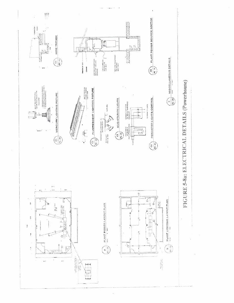
5.2.7 Low Voltage Switchgear
The low voltage switchgear will be of the indoor metal clad ciosed
cubicle with draw type circuit breakers. It wil! be fiirther equipped
with air breaking medium, protective relays, instments meter and
synchrosçope.
5.2.8 Auxiliary Service Supply
For auxiliary service supply, 3 units of 10 KVA single phase
transformer will be supplied for lowering the system voftage fiorn
7620 to 240 VAC. For DC siipply, a 48 volts for controi, proteçtion,
emergency & electronic equiprnent wili be supplied The battenes
will be equipped with charger
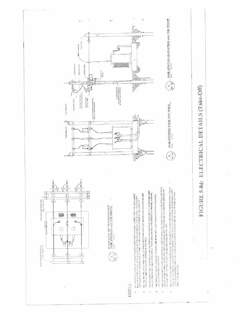
5.2.9 Switcb and Take-Off
The 13.2 KV take-off wiil be annexed to the power station. The step-
up transformer and take-off stnrctims will be located adjacent to the
powerhouse. The major configurations are, listed, to wit: Air break
switch (ABS), Lighting Anester, êircuit Breakers, Poles, Cross-ms,
Tnsulator, Bolts and Nuts, Crounding rod and çouplings.
5.2.10 Control and Protection Pane1
The power station witl be operated from the control and relay room
fiom where starhg, stopping and load and voltage control take place.
As a protective scheme, the turbine and the voltage regulating system
will be designed for automatic operation. Ai1 protection rejays and
devices wiH be located w i h the bdding.
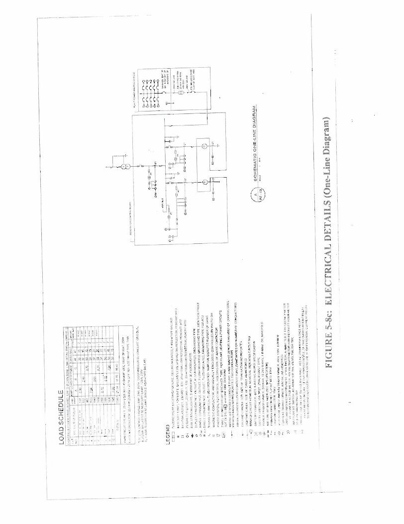
Referente is made to figures 5-5 anil 5-8 for the electro-mechanical
works schematic dragrarns.
Page 5-8
1 1 ( 1 ~ ~ ~ ~ ~ J ~ ~ i ~ ~ ~ ~ I ' I ..C Z W m I- C*. ..L W C I W
SECTION - 10 ._ -
FIGURIE: 5-2: PENSTOCK PRQFILE ---
- MERIOR a d INTERIOR E \ IADOER RUNO DEiNLS
FlGCIRE 5-4: SURGE TANK DETAILS
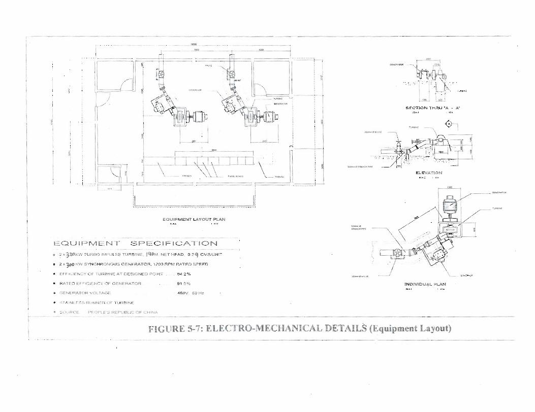
, - - - ---- EQUIPMENT ÇPECIFICATION
- - . - - .-- - - - - - - - - - - . 2 x3WKWTUfWO IMPWLSETURBINE. IYDM NET HEAD. O 24 CMSIUNIT
* 2 x p K W BYNCIIRONQUS GENERATOR. 1200 RPM RA'TEO SPEEO
EFFiClWY QF NRBINE AT DESIGNE0 POIMT 84 2%
i W L D EF FCIENCY OF GENERATOR Bt 0%
S0LiRCE PEOPLE'S REPUE)LIC QP CHINA
SECTiON :-A< Y H A U '& i I* - A'
FIGURE 5-7: ELECTRO-MECHANICAL DETAILS (Equipment Layout)
t
umi r a . ai.
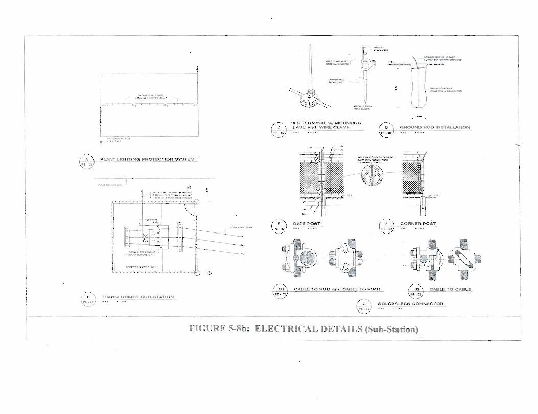
'AIR TERMINU W/ MOVMINO
CARU TO AOD 6nd CABLE TO POST
FIGURE 5-8b: ELECTRICAL DETAILS (Sub-Station)
CHAPTER 6.0: STABILITY OF GROUND SLOPES
6.1 INTRODUCTION
The stability of ground slopes relies on the geological and geotechcal
conditions of the pioject area based mady f?om surface geologic rnapping
and fiam available geological literatures.
Sub-surface investigation such as test pitting md sampling, auger boririg and
core dnlling, as necessary, will be undertaken during the detailed
enginee~g phase of the study. Such undertahg will define the rock
foundation characteristics at the proposed stmctures like weir, powerhouse,
headrace and penstock routes.
6.2 REGIONAL GEOLOGY
6.2.1 Physiography
Camarines Norte is clustered under the Bico1 sub-province of the
Eastem Physiographic Province, which co~istitute one of the bur-(4)
physiographic provinces that cornprise the Philippine Archipelago.
The classification and division of a physiographic province is based
on the island and submarine morphology.
Page 6- 1
T11c Bico1 sub-province extends fiom Southeni Siena Madre to the
southern tip of Rico1 Peninsiila and includes the islands of Polilio and
Catanduanes. The Bico1 PeIlmsiila fonns the soiithern parl of LJuzori.
Mt. Labo (942 m.) in the northern part of Camarines Norte is one of
the dormmt volcmoes along the eastern part. The eastern coast is
characterized by very irregular, deep and extensive coastal
embayments. The coastal feature of Barangay Colasi? . Mercedes,
Camtlranes Norie refle~ts this general chnracieristic having a deep
çoasta.1 embayment witl depth of about 80 meters
Pre-cretaceous schist's and quartzite's are tlte basement rocks in tlie
regioi~. Th~s rock suite is imcon-dortably overlained hy cretaceous to
quaternary volcanics and sed~i~~entary rocks wliich are separateci by
either faults or iincomformities.
The oldest terti-, sedimentw rocks resting on the nietamorphic md
volcanic rocks is the Universal Formation (Meek, etal 144 1) . This
fomztion is intrrided by diorite and related rocks. T l~e Universal
Formation is vo~npcsed of conglomerate, ar!rose, carbonaceoiis and
argillaceous shale ixqd limestone. Later intriision of Larap Volcanics
buried the Universal Formation. Subsequent depositiori of the Luurer
EvJiocene Bosigoi Formation overlain the Larap Volcanics with an
angrilar tmconformiíy.
Page 6-2
The lower member of the Bosigon Formation consists of
conglomerate, sandstone, calcareous shale and limestone. The upper
member is a thick intercalation of basaltic flows, volcanic wackes, tufT
breccias, cherts and limestone. Overlying tiie extensive Bosigon
Formation in C-es Norte distirict is the Sta. Elena Formation of
Late Miocene age. This sedunentary unit is a th~ck interbedded
sequence of conglomerate, sandstone, siltstone, shale and limestone.
The project area is believed to be located on the sedimentary units of
Sta. Elena Formation and Bosigon Formation.
The alluvid deposits consisting of unsorted to pooriy sorted and
unconsolidated soil, silt, sand and grave1 along flood plains and large
nver valleys cover the northeastern and eastem parts of the province.
The alluvial layer includes volcanic debris
From Fig. 6-1 (Fold Pattem) Carnarines Norte belongs to the NW-SE
system of major folds based on the axial trends. The NW-SE set
exhibit axial traces rangmg behveen N45W to NlOW.
The most significant normal or gravity fault in the Bico1 rejgon is the
NW trending fault in the central part of Camarines Sur that crosses
Ragay guif. Thnist faults on the other hand are located in the
northeastern parts of Canxines Norte, Carnarines Sur and
Catanduanes Island (Miranda and Vargas, 1967). as shown in Frg.6-2-
Cnistal Fractures Map of the Philipphes, as modified, in the MGB
publication of 1982.
Page 6-3
6.3 LOCAL GEOLOGY
The project area is on the southeastem coast of Camarines Norte bounded by
San Miguel Bay. Going inland, the topography is characterized by rolling
Mls to folded steep valleys or gorges. Low lying rounded peaks have top
elevation ranging from 245 meters to 400 meters, while the higliest peak
stands at 957 meters wherein the watershed limit is delineated.
Local thrust faulting aad folding have developed the steep riverbanks that
rises fkom 100 rneters to 400 rneters elevation. The Colasi River, which is
the hydro resource, flows through one of the river systems whose gorges
could be exploited for a medium length lieadrace distance and a gross head
of about 1 60 meters .
The river flows through three (3) waterfallldrops, a11 downstrearn of the weir
site. The water falls range in height fiom 20 m to 40 m. Outcrops of
sedimentary rocks consisting of sarid stone, conglomerate and few limestone
lined the river bed and river banks. The riverbed is littered with boulders of
sandstone and conglomerate and some volcanics. Flat areas observed at the
weir site are covered with sandy soil xnixed witll cobbles and boulders.
Nong the existing trai1 at right bank facing upstrearn, the soil cover is thin
and coinposed of sandy clay with losse weathered rock fiagments.
Page 6-4
6.4 ENGINEERING GEOLOGY
Geologicai Investigation was limited to surface geologic mapping at the
proposed weir site, headrace route and powerhouse site. Sub-surface
investigation to determine the foundation characteristics and slope stability
as well as the suitability of constniction materiais will be canied out at the
detded enpeering Ievel of study wherein the location of the weir,
headrace route and powerhouse have already been determined. Rock
exposures, however, indicate a stable ground slope condition.
Surface geologic mapping was conducted along nver channel fi-orn elevation
280 meters, which is the weir site to the powerhouse site at about elevation
120 meten.
6.4.1 Weir Antake
The propused m-of river diversion weir will be founded on the
massive sectlmentary rocks. The conglomerate and sandstone exhibit
irregular interbedding with traces of limestone layer on top. The width
section is about 20 meters. Ríverbed deposits of mostly boulders are
scattered along a 100-meter stretch downstream to the first waterfall
The width of the river channel narrows downstrearri as the left and
nght banks tum steep.
Page 6-5
6.4.2 Penstock / Headrace route
The penstockheadmce route is behg considered along the lefi bank
(facing upstream) of Colasi River because it has a shorter length than
Zocating it at the opposite bank. Both riverbanks have relatively steep
slopes. However, the right bank (facing upstrem) has a siightíy lesser
steep slope but would re@e much longer headrace route and wodd
necessitate at least four (4) major waterway crossing súuctures. At
elevation 125 meters, where the powerhouse site is proposed, the lefi
bank rises at an angle of 75 to 80 degrees to a height of about 50
meters. From thereon, however, the slopes of the left bank becomes
gentler, hence, much more convenient than the rigbtbank for the
laymg of penstock h e . Further, the LGU plaa to buiid an access road
at least up to the powerhouse area, on the left bank
The rock foundation along the route is solid mass of sandstone a i d
conglomerate. Fouradation of the penstock apparently will be on sound
rock. Where the ground is very steep, rock bolting may be required.
The slope surface are moderately to densely forest with second growth
trees that protects the slope fiom potential landslides. With m
underlying mass of rock with relatively thùi cover of about a meter,
the slopes appear stable. The rock surface does not show any
significint discontinuities of ffactu-ing due to forest cover.
Page 6-6
6.4.3 Powerhouse Site
The proposed powerhouse station i s located approximatel y 1,980
rneters downstream of weir site ninning at mild siope downstream
running along contour elevation 280 C-) meters. The difference in
elevation fiom the weir (elevation 280.80 m.) to the powerhouse
(elevation 125 m.) is 155.80 meters. The p u n d surface is made up of
conglomerate and sandstone cobbles ând boulders with thin veneer of
clayey soil of not more than a meter in thickness. The vicinity is fairly
covered with trees and bushes and heavy vegetatiori is noted above 20
meters fiom the river level.
At detailed engtneering phase, test pitting or auger borings are
recommended to probe into the depth and thjckness of the overbruden
composed of soil and cobbles/boulders but based on the outcrops, they
appear to be h. figh-angled joints are sparingiy seen and spaced at
1 .O to 1.5 meters. Some of tbe joints are open.
6.5 SEISMICITY
Seisrnicity of the region.can be assessed from shidies conducted jointly by
the Philippine Institute of Volcanalogy (PHTVOLCS) and the United States
Geological Society (USGS) in 1994 and pubIished with the btie "Estimates
of the Regional Ground Motion Hazard in the Philippines "
Page 6-7
The stiidy produced probabilistic gound rnotion hazard contow maps to
estimate peak ground acceleration ihat have 10 % probability of being
exceeded in 50 years for rock, inedium soil. and sofi soil site conditions. The
estirnates were caiçutated based on data fiom 2 1 seismic zones tiiat describe
the geographic content and íkequency of earthquake ocçwence for lhe
major tectonic elements of the Philippine region.
The authors adopted the ground motion attenuation equation deveIoped by
Fukushzma ãnd Tanaka in 1990 who assurned tliat regtonal attenuation
characteristics between the Western Paçifiç Içland are settings are similar.
The attenuation equation is:
LOG 10 A = 0.41M -LOGio (R = 0.032 x10 O 4 I M ) - 0.0034 R + 1.30
Where A = mean peak acceleration, crn!sec2
R = shortest distance between site and fault rupture, &I
M = surface wave magnitude
ln reference to the ground motion hazard maps, the project area belongs to
seismic source zone 7.0 (Figure 6-3) having a peak ground acceleration
estimated value of 0.23g (Figure 6-4) with a comesponding retum period of
50 years for the sedimentary rocks. For medium soil, the estimated value is
0.35 g (Figure 6-5) whle peak acceleration for soft soil is almost
doubled at 0.65 g (Fig. 6-7).
6.6 PHOTOGRAPHS
The subsequent paga sliow the surface geologic characteristics in
photographs.
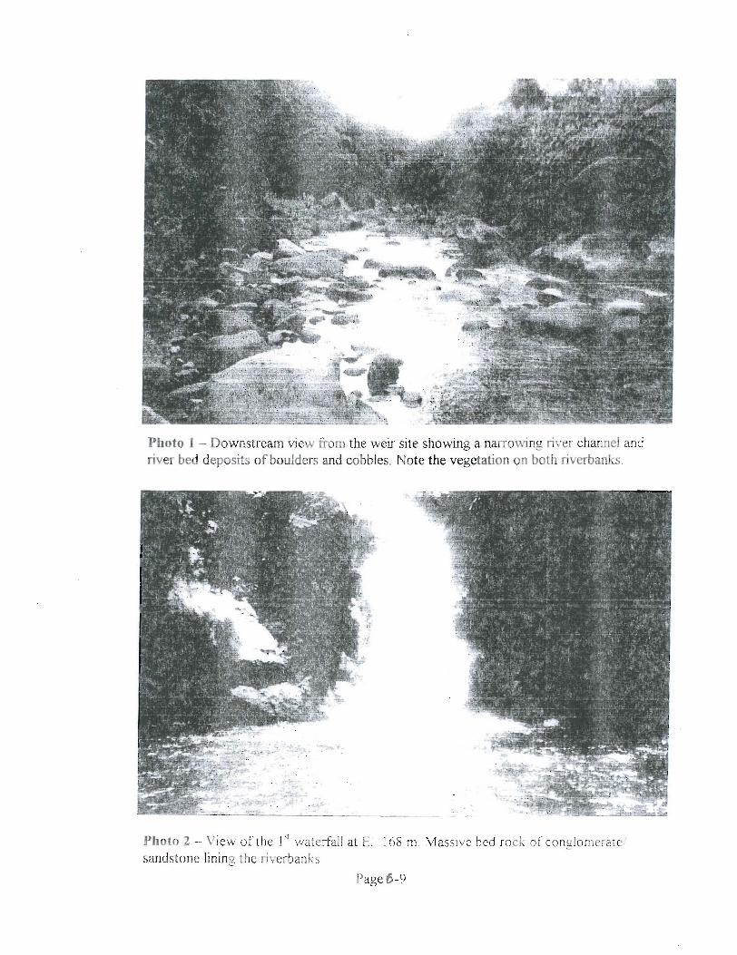
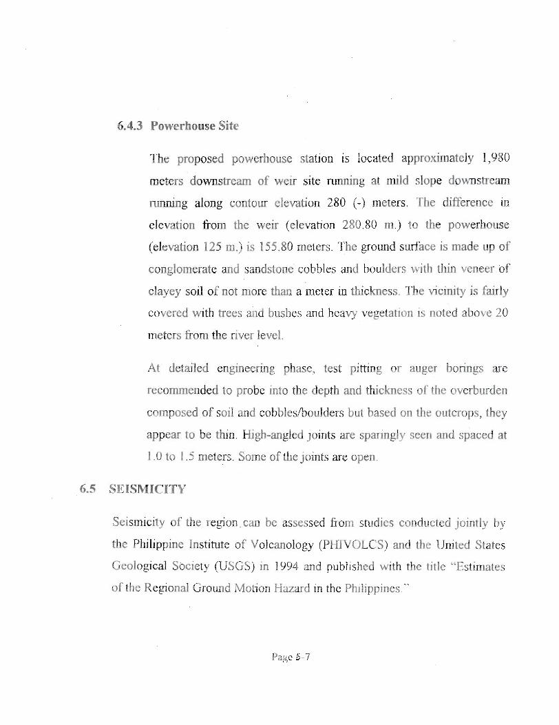
Photo 1 - Downstream view fiom the weir site showing a mowing river channel and river bed deposits of boulders and cobbles. Note the vegetation on both riverbanks
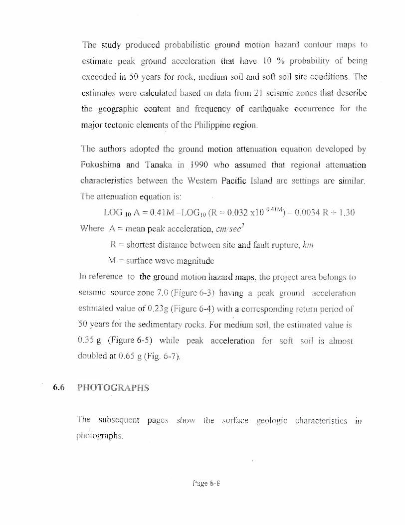
Pholo 2 - View ofthe l q waterfail at E1 168 rn Massive bed rock of conglomeratef sãndstone fining the riverbanks
Page 6 -9
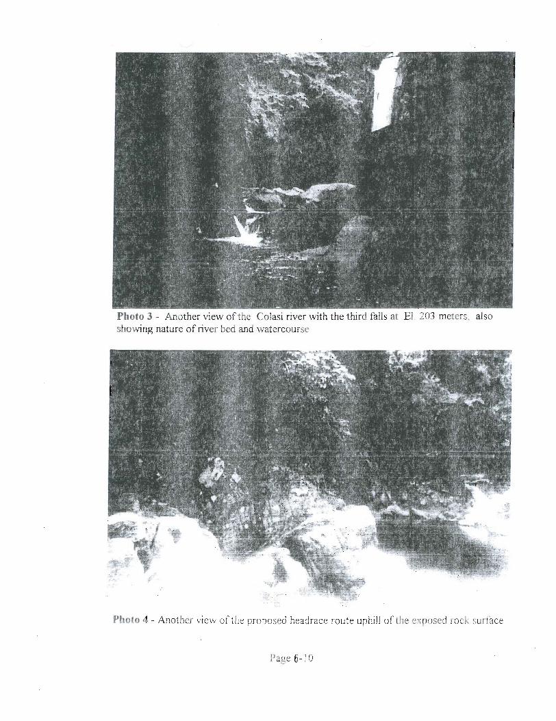
Photo 3 - Another view of the Colasi river with the third falls at EI. 203 meters. also showing nature of river bed and watercourse
*.
Photo 4 - Another view of the proposed headrace route uphill OS the exposed rock surface
Page 6- 10
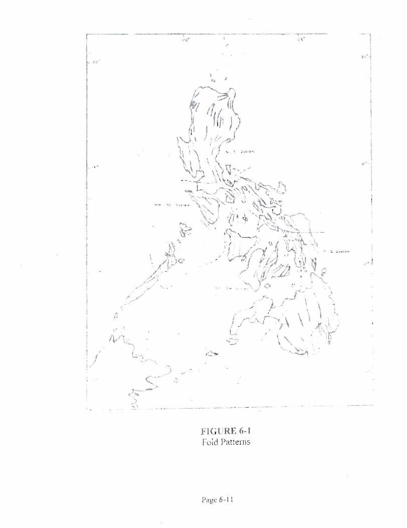
FIGURE 6-1 Fold Patterns
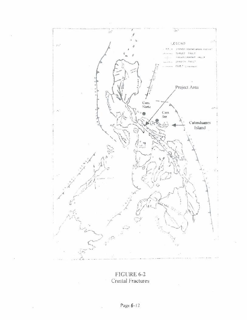
FIGURE 6-2 Crust a1 Fractures
Page O- 12
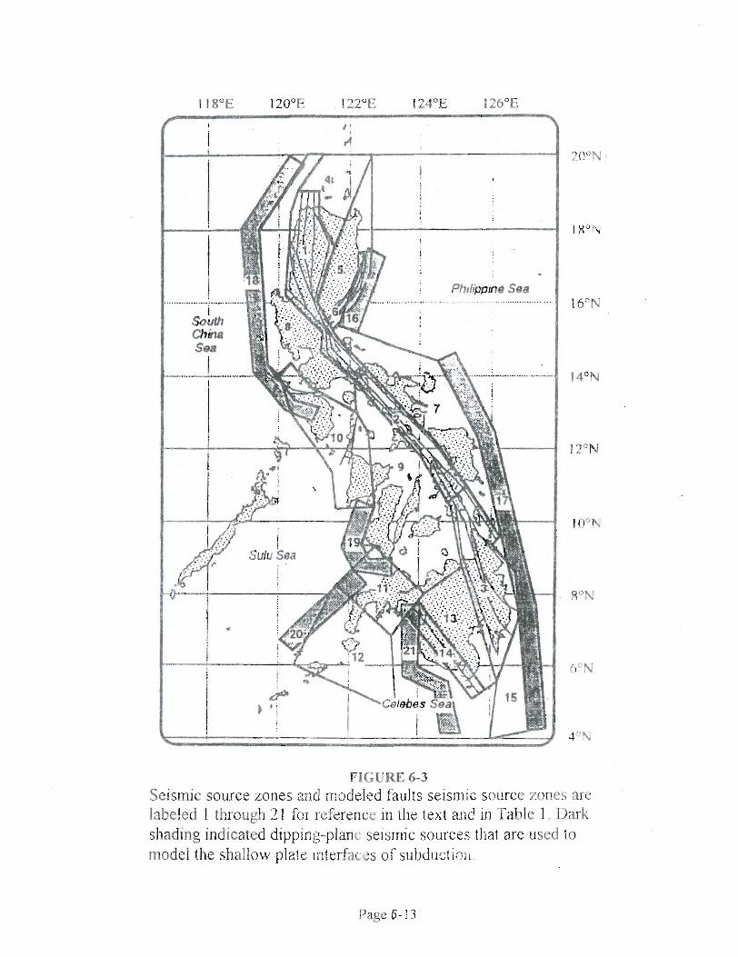
FIGURE 6-3 Seisrnic sowce zones and ingdeled faults seismic sowce zones are labeled 1 through 2 1 for referente in r11e text and in Table 1. Dark shading indicated dippi~g-plane seismic sources that are uçed to model the shallow plate interfaces of s u b d u ~ t i ~ i i .
Page 6- 13
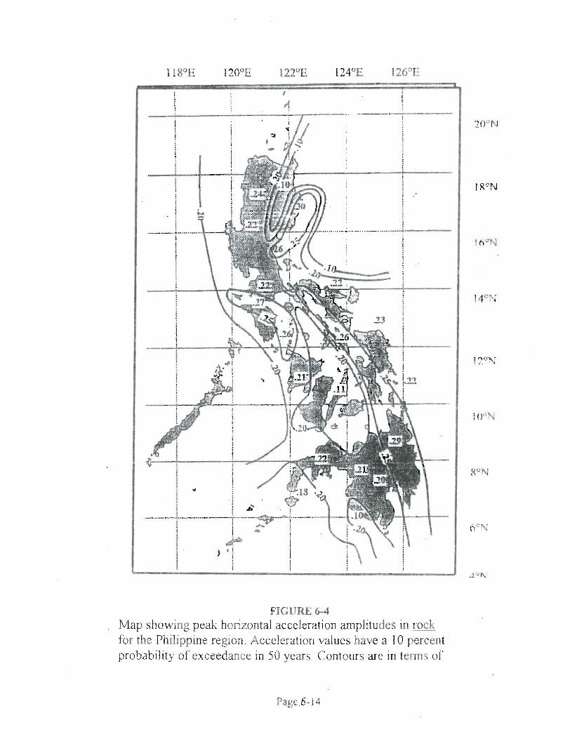
FIGURE 6-4 Map showing peak horizontal acceleratioil amplitudes in rock for the Philippine region. Acceleratiori values have a 10 percent probability of exceedance in 50 years. Contours are in terms of
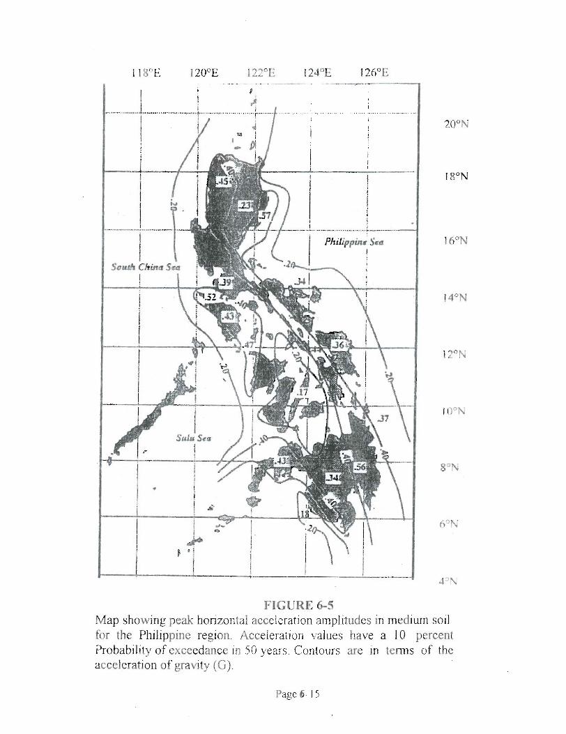
FIGURE 6-5 Map showing peak horizontal acceleration amplitudes in medium soil for the Philippine region. Acceleration values have a 10 percent Probability of exceedance in 50 years. Contotirs are in terms of the acceleration of gravity (G).
Page 6- 1 5
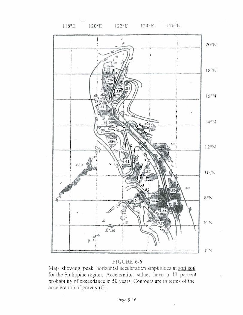
FIGURE 6-6 Map showing peak horizontal acceleration arnplitiides in soft soil for the Philippine region. Acceleration values have a I O percent probability of exceedance in 50 years. Contours are in terrns of the acceleration of gravity (G).
Page 6- 16