Embed Size (px)
Citation preview

WORKSHOP PLANROCKET SCIENCE
HISTORY OF GPS DEVELOPMENT
COMPONENTS OF THE GPS SYSTEM
HOW GPS GIVES US POSITIONS
METHODS & APPLICATIONS

LINK TO SLIDES:ftp://ftp.ngs.noaa.gov/dist/whenning/mssfall2011/

EVERY EPOCH OF OBSERVATION MUST COMPUTE CHANGE IN POSITION DUE TO EARTH ROTATION, SATELLITE ORBIT CHANGE AND RELATIVITY!
AT “C”, 1 NANOSECOND = 30 CM!


900+/- OPERATIONAL SATELLITES- HALF COMMERCIAL, MOST “LEO”& POLAR ORBIT-HUNDREDS OF THOUSANDS
OF PIECES OF SPACE DEBRIS

A SHORT HISTORY of GPS DEVELOPMENT • 1956 – Friedwart Winterberg (theoretical physicist at U of
NV) proposed test of general relativity using atomic clocks in satellites
• 1958 – Two American Physicists: William Guier & Weiffenbach (JHAPL), monitor Sputnik using Doppler effect principles of its radio signal to compute its orbit using UNIVAC II, leading to the development of the Navy TRANSIT system (using the reverse solution).
• 1960 – First Navy TRANSIT satellite launched. System of 5 satellites with 1 fix/hour.
• 1963 – Air Force “Project 57” 3-D LORAN-like system study births the GPS concept.
• 1967 – Navy places atomic clocks in space• Cold war arms race drives research using billions of dollars
for precise navigation for: submarine ballistic missiles, strategic bombers, and ICBMs.

HOW DID GPS EVOLVE?
• PRECURSORS:LORAN (WWII at MIT), DECCA NAVIGATOR (1940’S)
RADIO TRANSMITTER AT A KNOWN POSITION
RADIO TRANSMITTER AT A KNOWN POSITION
The difference between the time of reception of synchronized signals from stations A and B is constant along each LINE OF POSITION
RECEIVER

LINES OF TIME DIFFERENCE CAN DETERMINE POSITION
SYNCHRONIZED SIGNALS

• Labor day Weekend, 1973 – 12 military officers meet at the Pentagon create the “Defense Navigation Satellite System” (DNSS)- renamed NAVSTAR.
• 1978 – First experimental Block I GPS satellite launched• 1983 – President Reagan issues directive to make GPS
freely available for public use, after Korean flight 007 shot down over Russian airspace.
• 1985 – GPS command & control center moved to 2nd
Satellite Control Squadron at Falcon AF Station in Colorado Springs. 10 Block I satellites in orbit.
• February 14, 1989 – First Block II satellite launched• 1990-1 – Gulf war is first conflict where GPS is used. • 1993 – 24 satellites in orbit• April 1995 – Full operational capability declared by Air
Force Space Command.
A SHORT HISTORY of GPS DEVELOPMENT

• 1996 – GPS declared a dual use (military and civil) system by President Clinton
• Midnight May,1, 2000 - Degraded civilian signal (Selective Availability) ordered turned of at by President Clinton.
• 2004 – President Bush establishes National Executive Committee on Space Based Position Navigation and Timing(PNT)
• 2005 – First modernized GPS satellite IIR-M1 launched with L2C signal.
• April, 2010 – GPS satellite IIR-20M locks third frequency allocation with first L5 broadcast.
• Oldest operational GPS satellite is 21 years old (stated expected life was 7 years).
A SHORT HISTORY of GPS DEVELOPMENT

GLOBAL POSITIONING SYSTEM- Operated by NAVSTAR GPS Joint Program Office at the
Space and Missile Systems Center, Los Angeles Air Force Base, California.
NAVIGATION, SATELLITE TIMING AND RANGING


GPS GROUND CONTROL SEGMENT

GROUND CONTROL SEGMENT
Source: http://www.navcen.uscg.gov/cgsic/meetings/summaryrpts/

FUNCTIONS OF THE GROUND SEGMENT
Diagram Source: GPS System SegmentsArthur J. Dorsey and Willard A. MarquisLockheed Martin CorporationPeter M. FyfeThe Boeing CompanyElliott D. Kaplan and Lawrence F. WiederholtThe MITRE Corporation
Satellite-tracking-station on Hawaii(Source: Schriever Air Force Base Satellite Flyer Vol. 6; No.12)

ORBITAL ERRORS CONTRIBUTING TO PPM ERRORS
(See user guidelinesreferences forGraphic: Ahn, 2005)
2-5 m
1 cm!

GPS SPACE SEGMENT
GPS III-A

JUNK IN SPACE

LAUNCH HISTORY

GPS ORBITAL PLANES & SLOTS


GPS NAVIGATION MESSAGE

Each GPS satellite continuously broadcasts a navigation message at a rate of 50 bits per second (see bitrate). Each complete message is composed of 30-second frames, distinct groupings of 1,500 bits of information. Each frame is further subdivided into 5 subframes of length 6 seconds and with 300 bits each. Each subframe contains 10 words of 30 bits with length 0.6 seconds each. Each 30 second frame begins precisely on the minute or half minute as indicated by the atomic clock on each satellite.[61]
The first part of the message encodes the week number and the time within the week,[62] as well as the data about the health of the satellite. The second part of the message, the ephemeris, provides the precise orbit for the satellite. The last part of the message, the almanac, contains coarse orbit and status information for all satellites in the network as well as data related to error correction.[63]
All satellites broadcast at the same frequencies. Signals are encoded using code division multiple access (CDMA) allowing messages from individual satellites to be distinguished from each other based on unique encodings for each satellite (that the receiver must be aware of). Two distinct types of CDMA encodings are used: the coarse/acquisition (C/A) code, which is accessible by the general public, and the precise (P) code, that is encrypted so that only the U.S. military can access it.The ephemeris is updated every 2 hours and is generally valid for 4 hours, with provisions for updates every 6 hours or longer in non-nominal conditions. The almanac is updated typically every 24 hours. Additionally data for a few weeks following is uploaded in case of transmission updates that delay data upload.


NEW SIGNALS BOTTOM LINE:L5 (1176.45 MHz) , L2C (NEW CIVIL CODE)
• More robust•Faster AR• Stronger signal - lower carrier-to-noise-density ratio (c/n0) values than would otherwise be possible. • Better signal tracking & differentiation especially at lower elevations means better code positioning under canopy (the better cross-correlation performance means that the reception of weak gps signals is much less affected by simultaneously received strong gps signals, which can be of significant advantage in difficult signal reception conditions.) •Code iono error mitigation using L1 C/A, L2C, & P2 differencing (eventually L5 on block IIF & L1C on block III)•Longer baseline solutions•Faster ambiguity resolution•improved QA/QC with additional frequency checking•Faster, more accurate NAV updates• L2C has similar multipath characteristics as L1 C/A

“TIME”- WHAT DOES GPS USE?TAI / UT1 TIME
International Atomic Time (TAI) as a time scale is a weighted average of the time kept by over 200 atomic clocks in about 70 national laboratories worldwide based on VLBI measurements
UT1 is the principal form of Universal Time. While conceptually it is mean solar time at 0° longitude, precise measurements of the Sun are difficult. Hence, it is computed from observations of distant quasars using long baseline interferometry, laser ranging of the Moon and artificial satellites, as well as the determination of GPS satellite orbits. UT1 is the same everywhere on Earth, and is proportional to the rotation angle of the Earth with respect to distant quasars, specifically, the International Celestial Reference Frame (ICRF)

As of 1 January 2011 (2011 -01-01), 00:00:00 UTC, TAI was exactly 34 seconds ahead of UTC (this is the case since 1 January 2009): an initial difference of 10 seconds at the start of 1972, plus 24 leap seconds in UTC since 1972; the last leap second was added on 31 December 2008
“TIME”- WHAT DOES GPS USE?UTC TIME
Because Universal Time (UTC)is synchronous with night and day, and more precise atomic-frequency standards drift away from this, UT is still used to produce a correction (called a leap second) to atomic time, in order to obtain a broadcast form of civil time that carries atomic frequency. Thus, civil broadcast standards for time and frequency usually follow TAI closely, but occasionally change discontinuously (or "leap") in order to prevent them from drifting too far from mean solar time.

While most clocks are synchronized to Coordinated Universal Time (UTC), the atomic clocks on the satellites are set to GPS time (GPST):
The difference is that GPS time is not corrected to match the rotation of the Earth, so it does not contain leap seconds or other corrections that are periodically added to UTC. GPS time was set to match Coordinated Universal Time (UTC) in 1980, but has since diverged. The lack of corrections means that GPS time remains at a constant offset with International Atomic Time (TAI) (TAI – GPS = 19 seconds). Periodic corrections are performed on the on-board clocks to keep them synchronized with ground clocks
“TIME”- WHAT DOES GPS USE?GPSST TIME

GPS TIME
ORIGIN = JANUARY 1, 1980, ATOMIC TIME
DELAYED 19 SECONDS TO TAI AT ORIGIN
UTC IS DELAYED 15 SECONDS TO GPS TIME
TIME OF WEEK IN SECONDS FROM SUNDAY MORNING THROUGH SATURDAY NIGHT = 604799 SECONDS

“GNSS”
GLONASS
GPS
GALILEO
COMPASS (BEIDOU-2)

GPS USERS SEGMENT

EXPANDING GPS MARKETS
GIS INFRASTRUCTURE
MOBILE MAPPING SYSTEMS
MACHINE GUIDANCE


WHAT DATA DOES GPS NATIVELY GIVE ME?
NAD 83?NAVD 88?
LATITUDE, LONGITUDE?

-
Z
YX
-Z
-X-Y
ZeroMeridian
Mean Equatorial Plane
GNSS POSITIONS ARE ECEF, XYZ
ALL GPS SATELLITES’
POSITIONS ARE MAINTAINED IN
ECEF X,Y,Z(WGS 84 DATUM)

X,Y,Z TO φ,λ,h
φ
λ
Z Axis
X Axis
Y Axis
(X,Y,Z) = P (φ,λ,h)
hEarth’sSurface
ZeroMeridian
Mean Equatorial Plane
Reference Ellipsoid
P

ELLIPSOID, GEOID & ORTHO HEIGHTS
H88 = h83 – N09

NGS DTASHEET-E 167

E-167

GNSS TO ANY DATUM
• GNSS ECEF X,Y,Z (WGS 84 & PZ90)NAD 83 (φ,λ,h) SPC N,E,h
+ GEOID XX = SPC N,E,H
OR
“CALIBRATE “ TO 4-5 SITE POINTS IN THE DESIRED DATUM. THIS IS USED TO LOCK TO PASSIVE MONUMENTATION IN THE PROJECT
AREA.
EXAMPLE: GPS TO SPC + ELEVATION:

CONSTRAINING PASSIVE MARKS

GLONASS- FULL OPERATIONAL CAPABILITY 2010EUROPEAN UNION - GALILEOCHINA – COMPASS/BEIDOUJAPAN- QZSS FIRST LAUNCH 2010
CHANGES IN GNSS
GPS:• L2C• L5 CARRIER• New Code on L5• L1C1-3 m
BETTER RESISTANCE TO INTERFERENCEFASTER AMBIGUITY RESOLUTIONAUGMENTED CODE APPLICATIONS
10-15 cm???
= 115 SATELLITES?

IN TEN YEARS…….• 115+ SATELLITES
• 1.5 DM AUTONOMOUS POSITIONING
• NEW GEOMETRICAL DATUM – ITRF ALIGNED GEOCENTER BUT PROBABLY FIXED ON NORTH AMERICAN PLATE. NSRS ENTIRELY REALIZED BY ACTIVE STATIONS OF THE FOUNDATION CORS
• NEW NATIONAL GEOPOTENTIAL DATUM – 1 CM GRAVIMETRIC GEOID, ORTHOMETRIC HEIGHT SITE CONTROL TO 2 CM RELATIVE TO THE NATIONAL DATUM.
• MORE REMOTE SENSING: 2 - 3 DM SATELLITE IMAGERY/MAPPING , MMS
• INDOOR AND UNDERGROUND POSITIONING

TYPICAL GNSS EQUIPMENT• STATIC: ALL: FIXED HEIGHT TRIPOD, DUAL FREQUENCY
GPS RECEIVER (MAY HAVE GLONASS), GEODETIC ANTENNA, EXTERNAL OR INTERNAL BATTERIES, CELL PHONE, OBSERVATION SCHEDULE, MAP BOOK, LOG BOOK, VEHICLE.

TYPICAL GNSS EQUIPMENT• REAL TIME:BASE: FIXED HEIGHT TRIPOD, DUAL FREQUENCY
GPS RECEIVER (MAY HAVE GLONASS), GEODETIC ANTENNA, EXTERNAL BATTERIES, UHF RADIO GEAR OR DATA MODEM. ROVER: RECEIVER/ANTENNA INTEGRATED UNIT, CARBON FIBER POLE, DATA COLLECTOR, INTERNAL UHF RADIO (RECEIVE) OR DATA MODEM
SINGLE BASE ONLY BOTH SINGLE BASE & RTN

POSITIONS FROM GNSS OBSERVATIONS
• STATIC POST PROCESSING- USING PASSIVE MARKS
• STATIC ACTIVE STATION POST PROCESSING (CORS DATA)
• STATIC NGS POST PROCESSING (OPUS)• REAL TIME – YOUR BASE• REAL TIME – NETWORK SUPPLIED• AUTONOMOUS

WHAT CAN I EXPECT FROM STATIC GNSS POSITIONING?
NETWORK CAMPAIGNS: = SUB-CENTIMETER GEOMETRICAL WITHIN NETWORK, 2 CENTIMETER ORTHOMETRIC HEIGHTS
SINGLE POSITION: (CORS/OPUS) ≈ 1 CENTIMETER TO NSRS GEOMETRICAL WITH ≥ 4 HOURS, ≈ 5 CENTIMETERS ORTHOMETRIC HEIGHT

WHAT CAN I EXPECT FROM REAL TIME POSITIONING?
REAL TIME NETWORKS (RTN): A “FEW” CENTIMETERS. GEOMETRICAL. MOST RTN PRODUCE “GOOD” HORIZONTAL VALUES. OUR HORIZONTAL SYSTEM IS BASED ON ACTIVE REFERENCE STATIONS (NGS CORS), AS ARE THE RTN STATIONS. 7 OR 8 CENTIMETERS ORTHOMETRIC HEIGHT. BECAUSE ORTHOMETRIC HEIGHTS (‘ELEVATIONS’) ARE BASED ON PASSIVE MONUMENTS, THE RTN USER SHOULD, FOR THE MOST PART, CONSTRAIN THE PASSIVE MARK VALUES IN A LOCALIZATION.
SINGLE BASE: 2 CENTIMETERS REPEATABLE GEOMETRIC & ORTHOMETRIC HEIGHT TO A LOCAL BASE POSITION LESS THAN 10 K DISTANT. HOW DOES THAT BASE RELATE TO THE TRUTH?

WHY DOES MY CAR GPS GIVE ME ERRORS?
• Datum• Accuracy• Grid/ground• INS Degradation• Map errors

PRECISION VS. ACCURACY
•“PRECISION” IS A COMPUTED STATISTICAL QUANTITY TO THE SOURCE OF THE MEASUREMENT - ALIGNMENT TO THE RTN OR PASSIVE MARK SHOWS PRECISION OF THE OBSERVATION (PER THE DATA COLLECTOR).
•“ACCURACY” IS A COMPUTED STATISTICAL QUANTITY TO THE REALIZATION OF THE DATUM - ALIGNMENT OF THE RTN OR PASSIVE MARK TO THE NSRS SHOWS ACCURACY (PER ESTABLISHED METHODOLGY)•

PRECISION vs. ACCURACY
PRECISE – NOT ACCURATE
ACCURATE AND PRECISE
ACCURATE – NOT PRECISE

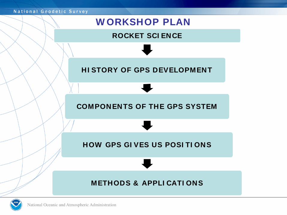
GPS SIGNALS- CODE PHASE
37 suitable codes are referred to as GOLD-codes (names after a mathematician). For these GOLD-codes the correlation among each other is particularly weak, making an unequivocal identification possible.
Navigation Data–50Hz Data, –Satellite Almanac, –Satellite Ephemeris,–Satellite Clock Error –GPS Time to UTC–Ionosphere Model parameters–User Range Accuracy(URA)

CODE MODULATES THE CARRIER WAVEPHASE MODULATION:When a data signal shall be modulated onto a carrier signal by phase modulation, the sine oscillation of the carrier signal is interrupted and restarted with a PHASE SHIFT OF 180°. This phase shift can be recognized by a suitable receiver and the data can be restored. Phase modulation leads to an extension of the frequency range of the carrier signal (leading to a spread spectrum) depending on how often the phase is shifted. When the phase changes, wave peaks are followed by wave minimums in a shorter distance than were in the original carrier signal (as can be seen in the graph).This kind of modulation can only be used for the transmission of digital data.
SOURCE:http://www.kowoma.de/en/gps/signals.htm

GPS SIGNAL STRUCTURE
PRN CODE MODULATION

GPS USERS SEGMENT
GPS SIGNALS- CARRIER PHASE

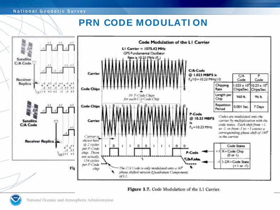
THE INTEGER AMBIGUITY
∆λ = First Partial WavelengthNλ = Integer Ambiguity
Resolving the integer ambiguity allows phase measurements to be related to distances
Distance = Nλ + ∆λ
WGS 84
X,Y,Z

L1 & L2 CARRIER PHASE
L1 = 1575.42 MHz = 154 x 10.23 MHzL2 =1227.6 MHz = 120 x 10.23 MHzAndL5 = 1176.45 MHz = 115 x 10.23 MHz
The wavelengths of the carriers are:λ1 = 19.03 cmλ2 = 24.42 cmΛ5 = 25.48 cm

WHY DOES GPS USE CERTAIN FREQUENCIES?Choice of the carrier frequency:To transport data signals, a suitable carrier frequency is required. -Frequencies should be chosen below 2 GHz, as frequencies above 2 GHz would require beam antennae for the signal reception-Ionospheric delays are enormous for frequency rages below 100 MHz and above 10 GHz-The speed of propagation of electromagnetic waves in media like air deviates from the speed of light (in vacuum) the more, the lower the frequency is. For low frequencies the runtime is falsified.-The PRN-codes require a high bandwidth for the code modulation on the carrier frequency. Therefore a range of high frequencies with the possibility of a high bandwidth has to be chosen.The chosen frequency should be in a range where the signal propagation is not influenced by weather phenomena like, rain, snow or clouds.
SOURCE:http://www.kowoma.de/en/gps/signals.htm

The ambiguity is an integer number (a multiple of the carrier wavelength).
The integer is different for the L1 and L2 phase observations.
The integer ambiguity is different for each satellite-receiver pair.
The integer ambiguity is a constant for a particular satellite-receiver pair for all epochs of continuous tracking (that is, as long as no cycle slips occur)
The carrier phase measurement from one observation epoch to another is a measure of the change in satellite-receiver range.
The determination of the cycle ambiguity integer is known as ambiguity resolution, and is generally not an easy task because of the presence of other biases and errors in the carrier phase measurement.
THE AMBIGUITY SEARCH….

SOME REAL TIME INTEGER FIXING TECHNIQUES-DUAL FREQUENCY ALSO ENABLES OTF
INITIALIZATION• Wide Laning (L1 – L2) = c (speed of light) ÷
(1575.42 MHz – 1227.60 MHz) or 299,792.458 Km/sec ÷ 347.82 MHz = 0.862 m wave length.
• Narrow Laning(L1 + L2) = c (speed of light) ÷ (1575.42 MHz + 1227.60 MHz) or 299,792.458 Km/sec÷ 2803.02 MHz = 0.107 m wave length
• Iono Free f(L1)ion-free = a1.f(L1) + a2.f(L2)
with a1 = f12/(f12 - f22 ) and a2 = - f1 . f2 /(f12 - f22 )
• Triple Differencing• Kalman Filtering• Double Differencing
INTEGER SEARCH

WHAT CAN AFFECT THE GPS SIGNAL?WHAT SHOULD I BE CONCERNED ABOUT WHEN
COLLECTING DATA?


IONO & TROPO LAYERS AND THEIR EFFECT ON THE GNSS SIGNAL

TROPOSPHERE DELAY
The more air molecules, the slower the signal (dry delay)High pressure, Low temperature 90% of total delayrelatively constant and EASY TO CORRECT FOR
The more water vapor in the atmosphere the slower the signal (wet delay)High humidity10% of total delayHighly variable and HARD TO CORRECT FOR

IONOSPHERIC EFFECTS ON POSITIONING
HIGH IONO-NO NETWORK
AVERAGE IONO- NO NETWORK
WITH NETWORK
(SOURCE-BKG- GERMANY)
DISTANCE TO REFERENCE STATION (KM)
2D
PR
EC
ISIO
N/
AC
CU
RA
CY
(C
M)
SINGLE BASE
RTK @ 10 KM
NETWORK SOLUTION
@ 30 KM
(1994-1995)(2000-2002)

IONO, TROPO, ORBIT CONTRIBUTE TO PPM ERROR
REMEMBER GNSS EQUIPMENT MANUFACTURERS’ SPECS!
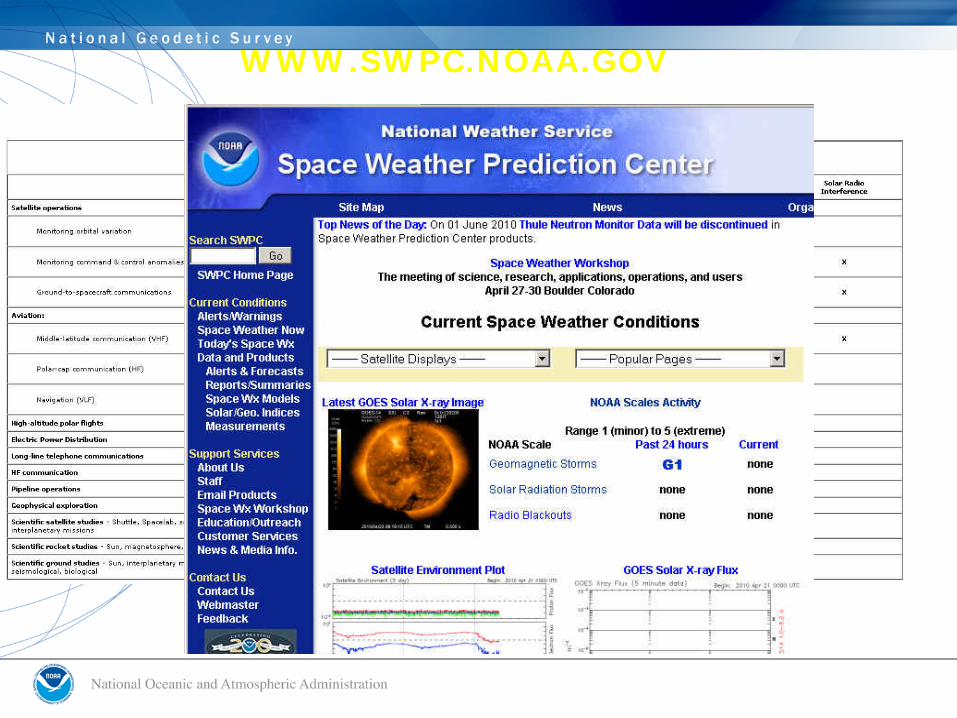
WWW.SWPC.NOAA.GOV

SUNSPOT CYCLE• Sunspots follow a regular 11
year cycle• We are just past the low
point of the current cycle• Sunspots increase the
radiation hitting the earth's upper atmosphere and produce an active and unstable ionosphere
2013
http://www.swpc.noaa.gov/

DILUTION OF POSITION = “DOP”UNITLESS PRN ERROR MULTIPLIER
HDOP = HORIZONTALVDOP = VERTICALPDOP = POSITION (HYPOTENUSE OF H & V)TDOP = TIMEGDOP = GEOMETRIC (PDOP + TIME)RDOP = RELATIVE (REAL TIME PARAMETERS)

SATELLITES/ DOP WITH OBSTRUCTIONS

SATELLITES/ DOP WITH OBSTRUCTIONS

DUAL CONSTELLATION RT POSSIBILITIES:GPS ≥ 5, GLN = 0 GPS = 4, GLN = 2 GPS = 3, GLN = 3 GPS = 2, GLN = 4 (Can't initialize with only GLN Sats.)
GPS AND GLN
BEST SCENARIO = 7 OR MORE GPSGLN “K” SATS WILL HAVE A CDMA (L3) FORMAT SIGNAL
WHAT ABOUT GLONASS?

GNSS CAN HELP IN URBAN CANYONS

GNSS CAN HELP IN CORRIDOR SURVEYS

GNSS CAN HELP IN OBSTRUCTED AREAS

AntennaType A
AntennaType B
DifferentPhase Patterns
Note that SV elevation and varying phase patterns affect signal interpretation differently

RELATIVE & ABSOLUTE ANTENNA CALIBRATIONS

THE TECHNOLOGY SWEET SPOT• SBAS: 2 M H, 6 M V, 0.3 M SMOOTHED H, CHEAP• COMMERCIAL DGPS: FEW DM, $$• USCG BEACON: METER+, CHEAP• DIFFERENTIAL LEVELING: 2-4 CM, LABOR/TIME INTENSIVE, $$$• GEODETIC LEVELING: mm, LABOR/TIME INTENSIVE, $$$$$• USER BASE RTK: 2-4 CM H, 3-5 CM V, REQUIRES INITIAL
INVESTMENT• RTN: 3-4 CM H, 5-7 CM V, REQUIRES INITIAL INVESTMENT(BUT ½
OF RTK)• AERIAL MAPPING: .10 M H, .20 M V, $$$• LIDAR: 0.10 – 0.3 M V• SATELLITE IMAGERY: 0.5 METER H RESOLUTION, 3 M LOCATION,
$$$• LOW ALTITUDE AERIAL IMAGERY: 2-4 CM H, 3-5 CM V, $$$• TERRESTRIAL LASER SCANNING: PROJECT SITES ONLY, 0.015 M H,
0.02 M V, REQUIRES INITIAL INVESTMENT

LightSquared• LightSquared, formerly known as SkyTerra and Mobile
Satellite Ventures (MSV), is based in Reston, Virginia.
• LightSquared is deploying an open wireless $14 billion broadband communications system with uplink (base station to handset) signals operating in the 1525-1559 MHz frequency band.
• LightSquared plans to provide coverage to the entire United States by deploying more than 40,000 ATC base stations by 2015.
• Recently, the Federal Communications Commission (FCC) conditionally approved an application for a waiver allowing LightSquared to repurpose the satellite spectrum immediately neighboring Global Positioning System (GPS) for use ground-based transmissions via Ancillary Terrestrial Component (ATC).
• Report on possible GPS Interference to be submitted by June 15

PROPOSED L1 BAND ALLOCATIONS FOR LIGHTSQUARED
1550.2 – 1555.2 Mhz
1526.3 – 1531.3 MHz
http://tmfassociates.com/blog

The Economic Benefits of Commercial GPS Use in the U.S. and The Costs
of Potential DisruptionNam D. Pham, Ph.D.
June 2011
DIRECT ECONOMIC BENEFITS OF GPS TECHNOLOGY ON COMMERCIAL GPS USERS ARE ESTIMATED TO BE OVER $67.6 BILLION/YEAR IN THE UNITED STATES $122.4 BILLION/YEAR
3.3 MILLION JOBS 5.8 MILLION JOBS AFFECTED
DIRECT ECONOMIC COSTS OF FULL GPS DISRUPTION TO COMMERCIAL GPS USERS AND GPS MANUFACTURERS ARE ESTIMATED TO BE $96 BILLION PER YEAR IN THE UNITED STATES, THE EQUIVALENT OF 0.7 PERCENT OF THE U.S. ECONOMY


URBAN AREA EXAMPLE

PBO STREAMS


CRADLE TO GRAVE GNSS!
Instead of looking for a traditional tombstone to mark the final resting place of a loved one, friends and relatives will be able to find the location of the deceased using a GPS device or mobile phone."The park will look very natural, just grass and trees. There will be no headstones and instead people will be buried in the park and a GPS locator placed in the coffin,” Michael McMahon chief executive of the Catholic Cemeteries Board told ABC News.
GPS Helps Track Babies in NurseriesHospitals all over the world are starting to use GPS to track newborns in their nurseries as a security measure.