Embed Size (px)
Citation preview

Daimler AG
Workshop on Automotive Stack Design Options, Platform Concept, and Cost Targets
AUTOSTACK Workshop Feb8th 2011, Grenoble
F. Finsterwalder

1
Content
1. Introduction
2. Summary of system requirements and stack specification
3. Conclusions for design options and platform concept
4. Critical trade-offs - Power density vs. Pt-loading

2
Autostack: The Objectives
• Analyze– vehicle requirements– supply industry– Cost and cost drivers
• Identify– synergy potential– Research needs
• Propose– Consitent dvelopment road map– Business model

3
Combining Expertise
3
AutomotiveOEMs
ResearchInstitutes
Component and System Suppliers
Autostack Consortium

4
Tackling the Issue
OEM-System Reqirements
Stack Platform Definition
Detailed Stack Specifications
Component Requirements
Supplier Survey
Component Performance
Stack Specifications
„Top-Down“
„Bottom-Up“
Virtual Stack Design

55
Project Workflow
WP1 OEM System RequirementsWP1 OEM System Requirements
WP2 Supply Chain & ResearchWP2 Supply Chain & Research
WP4 Business ModelWP4 Business Model
WP3 Road MapWP3 Road Map
01.01.2010
30.06.2011

7
Micro-Kompakt
Klein-laster
B-EV
FC-EV
SchwererLKW
MittlererLKW
Überland-BusCity-BusLuxus- &
Familien-FzgeMittel-Klasse
Kompakt-Klasse
possible Possible with restrictions Today not possible
Suitability of Battery / Fuel Cell Drive Train for Various Vehicles
E-Drive-Portfolio – Opportunities and Limitations
Long Distance Interurban Urban
Fuel Cell
Battery Drive
Combustion Engine
Hybridization
Plug-In/Range Extender

8
FC System Concept:Basic Requirements to Observe
• Power / gravimetric / volumetric Power Density• Cost • Durability• (Freeze)-Start-up time• Efficiency superior to any (hybrid)-ICE• One Fuel on Board (H2)
These requirements strongly reduce the number of system options…
comparable to ICE

9
Automotive System Architecture
M
anode
cathode
coolant
MM
humidifier
radiator
MM
H2-blower
M
anode
cathode
coolant
MM
humidifier
radiator
MM
Simplified schematic
Features:• Air compressor without
expander• Gas-to-gas humidifier
(cathode out cathode in)
• High power density stack• An active / passive
H2 recirculation pump p = 1 .. 2 bar abs
T = 55 .. 95°C max (outlet)
Rh cathode @ max power = 50%

14
Conclusion
• FC-systems designers have to respect many ambitious requirements. The number of concepts able to fulfill these requirements is small
• OEMs participating in AUTOSTACK have agreed commonly on a system concept of choice
• Other promising system concepts exist, are however not broadly accepted within the automotive industry. Still, they should be further considered, in particular for the earlier markets.

17
Components Considered Part of the Stack
• Bipolar plates, MEA, Seals• Current Collectors + end plates• Stack compression kit• Casing / Housing (also for EMC*)• Flanges (quick connectors)• HV-Contactors + interlock• Vehicle mounts (brackets)• End cell heaters (PTCs) integrated in the stack enclosure – may be used for
stack discharge• Sensors (also for diagnostic purposes - may be removed at a later stage):
– Pressure: Coolant in- and outlet, Fuel in- and out, Oxidant in- and out– Temperature: Coolant in- and outlet; Fuel in- and out; Oxidant in- and out, End Cells– RH-sensors in the header (manifold part)
• Cell Voltage Monitoring Unit: – This will be required during development phase - Aim is to remove CVM– Already today, control strategy must be developed without the need for individual cell
voltage monitoring!
*electromagnetic compatibility

19
High Level Stack Requirements
Stack nominal power (gross, continuous) 95 kW (requirement)(System power 80 kW)
Stack Open Circuit Voltage <430 V (requirement)(limit set by power electronics – consider OCV > 1V @ freeze T)
Minimum stack voltage >200 V (guidance)(limit depending on E-motor and DC/DC converter characteristics)
Weight <60 kg
Volume <50 l
Operating Temperature min -25°C (start capability)max +95°C (outlet temp.)
Interface parameters at nominal powerPressure 2 baraAir Stiochiometry 1,6 Humidification 50%

20
Plate Design
Area Power density 95 kW, 1 W/cm2
Cell voltage at nominal power 0,67 VCurrent density at nominal power 1,5 A/cm2
Active area of stack 9.5 m2
Number of cells (1-row stack is a requirement) 300 .. 380 (stack height!)
Active are area per cell (projected) 317 cm2
Plate Area (a.a. = 60% of plate area) 528 cm2
Cell pitch 1,5 mm
Ci
Ao
Ai
Co
Wi Wo
Active Area (aspect ratio 1:3)PortRegion Transition
Region
Preliminary Plate Design (1 Path parallel Flow Field)
30,8 cm
10,3 cm
Plate Dimensions:11,3 x 46,8 cm2

22
Degradation Targets
• Throughout its lifetime the stack is allowed to degrade by 10% in max. power output, i.e. 1 W/cm2 0.9 W/cm2
• The max power is limited by the cooling power• Therefore, the stack will be operated at maximum waste
heat during its life• As the stack degrades, the max power point will move to
lower voltage and – in order to keep the waste heat constant – to lower current density, i.e. max power point moves along the “iso-waste heat” curve

24
Operating Strategy and Turn-Down Ratio
• The stack can be operated efficiently and stable within certain limits (highest power/lowest power = turn-down ratio)
• This results from the conflict of flow homogeneity vs. pressure dropknown in fluid dynamics
• Very low and very high power demands will be covered by the battery Hybridization
• This implies a start/stop strategy for the stack• The stack will be switched of between
5% and 10% of its nominal power,i.e. 5 kW .. 10 kW (= the required size of the battery. This corresponding to a TDR of 1:10 .. 1:20)
Pre
ssur
e dr
op
in s
tack
Current density / volumetric flow / load
pmax
pmin
p high
p low
Efficiency lossesStable operation
Stable+efficientoperating regime (determines the turn down ratio)

27
acceleration H2 depletion
deceleration high p
between A / C
low power stack stop extended stop O2
ingressPotential cycling catalyst corrosion?
Drive Cycle Analysis
Stress Factors in a “Real” Drive Cycle

31
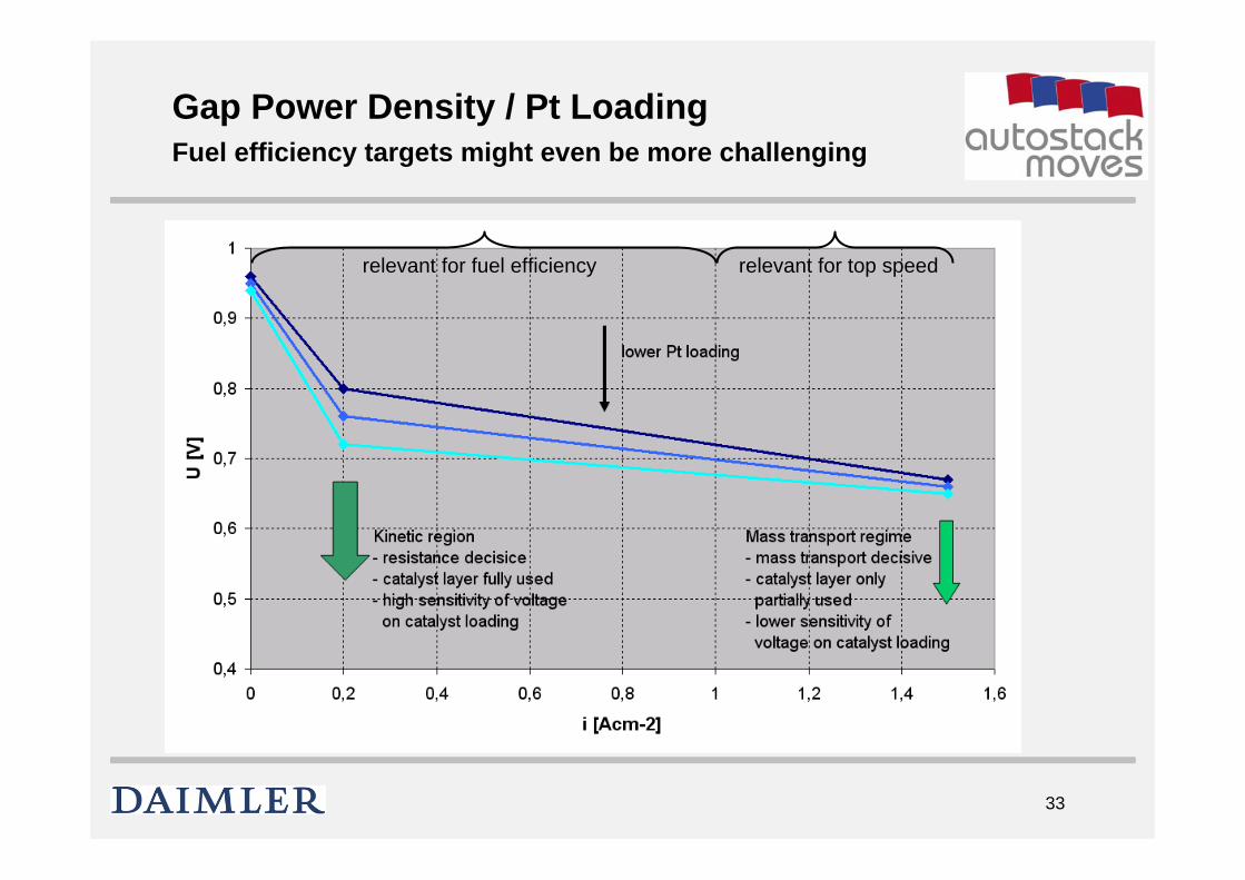
Conflicting Targets / Major Gaps
Power Density / Efficiency
Pt loading Durability
1 W/cm2 / 0.8 V @ 0.2 A/cm2
0,16 mg/cm2 5000 hrs, >20,000 starts
33
Gap Power Density / Pt LoadingFuel efficiency targets might even be more challenging
relevant for fuel efficiency relevant for top speed

36
Optimize the €/kW Parameter- with a given catalyst layer technology
Save Membrane?high Pt loading, small membrane area
Save Platinum?low Pt loading, large membrane
area
Pt Ptmembrane
Finding the best compromise between Pt loading and power density

39
Pt Loading Variation (logarithmic fit)and Resulting Stack Power Costs

41
Summary & Conclusion
• The cost optimized Pt loading is influenced by:- the costs of membrane, GDL, BIP vs. Pt- the power density characteristics of the MEA
• With today’s MEA technology and price structure do not address low Pt loading at the expense of power density
• Power density is paramount target.High power density allows standardization, thus cost reduction

42
Standardization & Economies of Scale
higher power density higher degree of freedom (packaging)
standardizationeconomies of scale (1)
Pt reduction economies of scale (2)Addressing ultimate cost targets
Addressing product design targets
market volume

43
Thank you very much for your kind attention