Embed Size (px)
Citation preview

© 2015 ANSYS, Inc. November 7, 2016 1
16.0 Release
Workshop 05Surface Mesh Preparation - ASMO
Introduction to ANSYS Fluent Meshing

© 2015 ANSYS, Inc. November 7, 2016 2
Workshop Description:
This workshop shows some of the clean up tools in Fluent Meshing for boundary meshes.
Learning Aims:
You are going to use the tools to clean up the given surface mesh and generate a volume mesh.
This workshop will cover how to
– Create and display groups
– Visualize problem areas
– Use global and local tools for cleaning up the mesh
– Check quality of mesh
– Improve quality using global and local tools
– Use the new Fluent Meshing Icons.
– Use Troubleshooting techniques
– Generate mesh and improving its quality
– Set zones and boundary conditions
I Introduction

© 2015 ANSYS, Inc. November 7, 2016 3
– Open the Fluent Launcher by clicking the Windows Start menu, then selecting Fluent 16.0 in the Fluid Dynamics sub-menu of the ANSYS 16.0 program group
– Enable Meshing Mode under Options– Select Serial for Processing Options– Set Working Directory to the area where files are– Click OK to start Fluent in meshing mode.
Starting ANSYS Fluent in Meshing Mode
Note: This tutorial uses the newly introduced
Icons for improving the surface mesh. Fluent
Meshing needs to be launched in serial mode to
display these icons.
The workshop geometry is a simple half-car
geometry in a wind tunnel.
For this workshop, We read the surface mesh,
identify and fix issues with it, before proceeding
to volume mesh generation.

© 2015 ANSYS, Inc. November 7, 2016 4
File Read Mesh...• Select the mesh file • ASMO_NS-for-repair.msh.gz and
click Open• This is read in as a geometry object.• Right-click on “Asmo” object and
click draw to display. • Select Zone selection filter and
select the outer walls of wind tunnel.• Click on hide icon to see details of
the car.• Right-click on “Asmo” to get a
summary of the imported geometry.• Problems with surface mesh are
highlighted in the summary .
Read and display the mesh

© 2015 ANSYS, Inc. November 7, 2016 5
We now use visualization tools inside Fluent Meshing to identify issues with the surface mesh.
• Enable Free and Multi under Set Face Options
The zones marked in blue are the free faces which have to be fixed.
Visualization of Problem Areas
• Disable “All” from the Face Optionslist dropdown to easily highlight all the problem areas.
There are various global and local tools inside Fluent Meshing which can be used to fix such connectivity issues.
R16.1

© 2015 ANSYS, Inc. November 7, 2016 6
Merge Nodes
• Right-click on Asmo object, hover your mouse over Diagnostics and click on Connectivity and Quality to open Diagnostic tools.
This tool will help to identify the problematic areas for the surface mesh and to fix most of it.
• In the Face Connectivity tab,
• Select Free as Issue and Merge Nodes as Operations
• Enable the option of Relative (Percent) Tolerance
• Retain the default value of 10%
A local tolerance based on 0.1*edge length is used.
• Click Apply for All.
• The message in console displays the number of boundary nodes and faces merged.
• Click Draw in the dialog box to redisplay the
free faces.
Note that number of free faces has significantly reduced.

© 2015 ANSYS, Inc. November 7, 2016 7
Merge Nodes with Increased ToleranceIf you zoom in, you can notice that some of the
nodes with bigger tolerance difference have not been merged.
They require more than 10 % tolerance to be merged. You can increase the tolerance in steps of 10 till you reach 50 % and observe the change.
• Select all the Objects in the Diagnostics Tools and increase Tolerance by 10.
• Merge and Draw.
• Enable All Face Visibility. You may need to hide the wind tunnel walls again.
• Repeat for 30%, 40% and 50%, redrawing each time to see the effect on the connectivity
Each step improves the connectivity of the
mesh, reducing the number of free faces.
Write the mesh
FileWrite Mesh
ASMO_Nodes_merged.msh.gz

© 2015 ANSYS, Inc. November 7, 2016 8
StitchNodal mismatches can be too big for Node Merge to deal with. You can instead Stitch the nodes for large tolerance node merging. We advise saving the mesh before this is used as it can destroy geometry if used incorrectly. Always Merge Nodes first.
• In Diagnostics Tools , ensure Issue selected is Free
• Change operation to Stitch
• Mark all free faces within tolerance (0.05)
• Click First to go to the first set of the free faces about to be stitched
• Click Apply for All then hit Draw to see the effects.
• Observe that this fixes most of the free faces.
• We will now fix any remaining free face issues with local, manual methods.
1
2
3
45
Write the mesh
FileWrite Mesh
ASMO_Stitched.msh.gz
6

© 2015 ANSYS, Inc. November 7, 2016 9
• Switch on Remesh Caps option from Display Controls… as shown. This will remesh the caps created while filling holes.
• In Diagnostics tools, Mark the Free faces
– This time the marked faces will be considerably less than in previous operation
• Click First in Diagnostics panel
– This will highlight faces around the hole on rear wheel housing. Select visibility of all faces to improve the view.
• Clear face selection by clicking (F2) ,select Edge selection filter (Ctrl-E), select an edge on the open loop and click on the create icon (F5) to fill the hole.
– Remember, middle mouse click centres the view on a point and then you can rotate or zoom on that point easily. Up and down arrow keys can be used to increase the delta for bounds
Fixing Final Free Faces
Note: If you do not clear the free faces
before selecting the face zone, you will get
an error message. This is because repair
operation expects only the zone id as
input.
RMB

© 2015 ANSYS, Inc. November 7, 2016 10
• Click Next in the Diagnostics Tools panel.
• This will highlight the next set of free faces not fixed by the stitch operation. Clear the selection ( F2) Ensure Edge selection icon is activated and select an Edge on the open loop with RMB then use the Create icon to fill the hole.
• Use Next and repeat the above process for the next hole by clearing selection, picking an edge and using Create icon.
– You can use the ctrl + right-click sticky key to repeat the previous operation. In this case, ctrl + right-click will allow you to repeat the “create” operation.
Fixing Final Free Faces

© 2015 ANSYS, Inc. November 7, 2016 11
• Local fixing of boundaries can be done using the newly introduced icons in the graphics panel.
• Click next to select the next cluster of free faces as shown in the picture.
• This could be rectified by filling as before but the resulting triangle would be highly skewed so we can fix in another way.
• The next 2 slides show how to fix this issue using the icons. The appropriate icons are indicated in each image.
• Note the Boundary Modify panel can also be used to do these operations.
Local Cleanup – Using GUI icons

© 2015 ANSYS, Inc. November 7, 2016 12
Local Clean Up Tools – Using Icons
• After creating caps in previous steps you reach a stage as shown in the figure where there is no node pair to merge.
• First clear all selections .
• Click on node Filter (Ctrl-N) , select the two nodes in order as shown then click the merge icon (F9)
• Tip : Always click into the corner of the tri nearest the node/edge you wish to select rather than trying to directly click the node/edge position itself.
• Click next and you should be left with just one free face.
1
2
Edge Split
Merge Nodes

© 2015 ANSYS, Inc. November 7, 2016 13
Local Clean Up Tools – Using Icons
• Click Next in Diagnostics to take you to the next problem area as shown
• First clear all selections .
• We could merge nodes only again but here we will split an edge and then merge
• Click on the Edge Filter icon (Ctrl-e) , select the edge as shown and Split the edge using (F7)Then switch to nodeFilter (Ctrl-n) , and select the two nodes in order as shown and merge using
(F9) .
• You should be left with just one free face. 12
Edge Split
Merge Nodes

© 2015 ANSYS, Inc. November 7, 2016 14
• If we click Next again for “Free” issue we find the issue below which is both Free and Multi. Let’s look at the Multi tool to see how it works
• Select all boundary zones in the Diagnostics tool list
• Select Issue as Multi in Diagnostics tool panel
• Retain all other values as default and click Mark
• By clicking on First, first set of multi-connected faces will be shown with default bounds around the set
– One can use up and down arrow keys to increase/decrease the bounds to improve visibility.
• Click Apply for Current this will delete one fringe face
• Click Summary now to see if any free/multi faces are present. There should be none left.
Clean Up “Multi” Connected Faces

© 2015 ANSYS, Inc. November 7, 2016 15
Fixing Self-Intersections• Check for Self Intersections in the geometry
• Change Issue to Self Intersections in DiagnosticsTools panel and Mark
• Click First to go to First set of faces
• Click Smooth All to smooth the spike penetrating the mesh
• Draw to view to smoothed faces
• Click Mark again to verify they are all fixed
• Click Summary to see what issues remain
1
2
3
4
5
Note self intersection
checks are not included
in Summary due to
expense of calculation
for large models. We
advise to check prior to
volume meshing.

© 2015 ANSYS, Inc. November 7, 2016 16
• Once there are no Free or Multi faces we can verify connectivity and move on to worry about the quality of the surface mesh
• Ensure that you have Bounds Reset so that you can see the whole geometry and check one last time for Free and Multi faces visually
• Use Ctrl+A hotkey or the button to auto-scale the view to the screen
• Fix any remaining issues if free or multi exist (previous steps may have not been followed exactly!) The Diagnostics Summary should look like this with no free, multi or duplicate but with some skewed faces to fix.
Verify Connectivity
R16.1

© 2015 ANSYS, Inc. November 7, 2016 17
Fixing Poor Features
• Here we fix a kink in the roof• Zoom on the area highlighted
• Switch to Node Filter • Select two nodes as shown below• Set target edge based on 2 nodes (Ctrl-s)• Select the node to project as shown• Project (Ctrl-p)
Set Target Edge Project to targetSelect Nodes Select node to project
Will clear the target edge from display

© 2015 ANSYS, Inc. November 7, 2016 18
Rezoning Triangles• In Graphics window select the car-front boundary zone
(highlighted) and Isolate (Ctrl-Shift-i) it • You can see that the feature edge is not smooth and some
triangles should belong to car-main-body• Clear selection using , Switch to face Filter and select the
faces required to rezone into car-main-body (hint: rotate shows them clearly by their edges). You can also use box select.
• Now go back to earlier display of car • Switch to Zone Filter and select the car-main-body in the
graphics window with RMB (as shown red below)• Click on (Ctrl-o) to rezone the triangles into car-main-body

© 2015 ANSYS, Inc. November 7, 2016 19
Improving Quality• In Diagnostics Tools panel switch to Quality Tab. Switch
Operations to General Improve, change Min Skewness to 0.7 and Mark the skewed elements > 0.7
• Retain default options (e.g. Preserve Boundary is switched on) and click on First to visualize problem areas.
• After these faces are marked hit Apply for All
• This should reduce max skewness to 0.69.
Note: You can also see all the faces marked one by one by hitting First and Next each time if you wish to resolve the issues manually. This will show the locations where Mesh is going to improved which you can check afterwards and is more useful when the number of issues are small.
Click Summary again to verify that there are no connectivity or skewness issues left and that we can move to volume meshing.
Improved mesh

© 2015 ANSYS, Inc. November 7, 2016 20
• We have ensured connectivity and quality of this Object manually
• We can now force the Geom type object through as a Mesh Object
• Open the Objects panel
• Select “asmo” Object
• Right-click and select Convert to Mesh Object
• Click yes on the following dialogue box
Switch to Mesh Type
© 2015 ANSYS, Inc. November 7, 2016 21
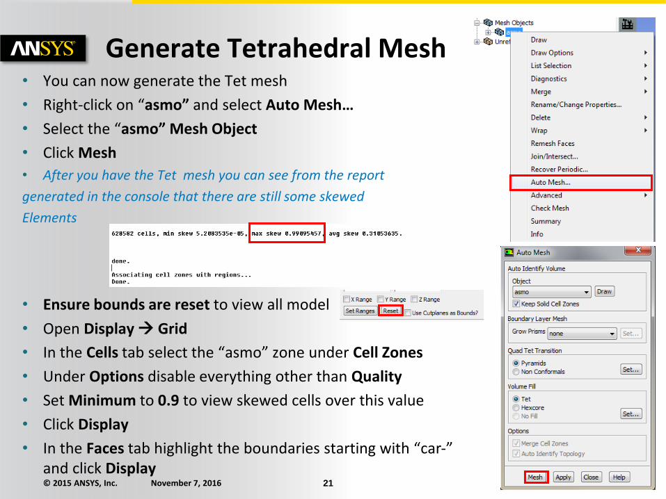
• You can now generate the Tet mesh
• Right-click on “asmo” and select Auto Mesh…
• Select the “asmo” Mesh Object
• Click Mesh
• After you have the Tet mesh you can see from the report
generated in the console that there are still some skewed
Elements
• Ensure bounds are reset to view all model
• Open Display Grid
• In the Cells tab select the “asmo” zone under Cell Zones
• Under Options disable everything other than Quality
• Set Minimum to 0.9 to view skewed cells over this value
• Click Display
• In the Faces tab highlight the boundaries starting with “car-” and click Display
Generate Tetrahedral Mesh

© 2015 ANSYS, Inc. November 7, 2016 22
To view the cut plane through the wheels:
• Zoom in on the bad (red) elements.
• Select position Filter (Ctrl-x), and right-click to select a position at the center of the element group as shown
• Since you want to look at a cut plane in Y direction, Click Set Ranges with delta of zero and make sure that Y Rangeis checked while X and Z Ranges are unchecked
• In the Cells tab of Display Grid dialog box enable Bounded and click Apply and Display
• You can see the problem areas down in the corners where there are sharp angles.
• Try switching the Y Range for Z Range or X Range to see cut planes in different directions
View Cut Plane
Zoom In Zoom In

© 2015 ANSYS, Inc. November 7, 2016 23
To fix the skewed cells we can:
• Clear the mesh and repair the boundary again or
• Do local smoothing using the Auto Node Move tool
This will move the local nodes to improve quality. We will select boundaries to allow movement but we will restrict movement along the surfaces to avoid changes to the geometry
• Open Mesh Tools Auto Node Move…
• Select all the Boundary Zones.
• Retain the default settings and click Apply.
A message will be printed in the console about
improved quality. Click Apply for few more iterations
and the quality will improve. Once it is brought to an
acceptable level the mesh is ready for the solver.
Dropping Dihedral Angle and deselection of “restrict boundary nodes along surface” will allow more aggressive improvements and better quality but risks loss of features
Improve Quality

© 2015 ANSYS, Inc. November 7, 2016 24
• Reset the Bounds and RMB on “asmo” under “cell zones” and Draw
• Set zone filter and select the inlet (wind tunnel inlet) in the graphics as shown.
• Select the pencil icon to change properties of the selected zone
• Select “Set Boundary Type” and select velocity-inlet from the drop-down list.
• Click OK.
• Similarly set outlet zone to pressure-outlet type, and symmetry zone to symmetry type
• RMB on “asmo” cell zone and click Summary and Info to see more info on the cells e.g. type, count and quality
Boundary Conditions

© 2015 ANSYS, Inc. November 7, 2016 25
• RMB on Model in the Tree and select Prepare for Solve and answer Yes
• This removes un-needed geometry objects and removes numbers from our face zone names etc before moving to the solver
• Now write the volume mesh.
File Write Mesh…
ASMO_Meshed.msh.gz
• Enter a proper name for the mesh and click OK.
• Optionally, switch to Fluent solution mode and continue to solve
• Remember to scale the mesh!
Mesh Ready