Embed Size (px)
Citation preview
Worksheet 6
To accompany Chapter 3.3 Using Laplace Transformsfor Circuit Analysis
ColophonThis worksheet can be downloaded as a PDF file. We will step through this worksheet in class.
An annotatable copy of the notes for this presentation will be distributed before the third class meeting as
Worksheet 6 in the Week 3: Classroom Activities section of the Canvas site. I will also distribute a copy to
your personal Worksheets section of the OneNote Class Notebook so that you can add your own notes
using OneNote.
You are expected to have at least watched the video presentation of Chapter 3.3 of the notes before coming
to class. If you havenʼt watch it afterwards!
After class, the lecture recording and the annotated version of this worksheet will be made available through
Canvas.
Circuit Transformation from Time to ComplexFrequency
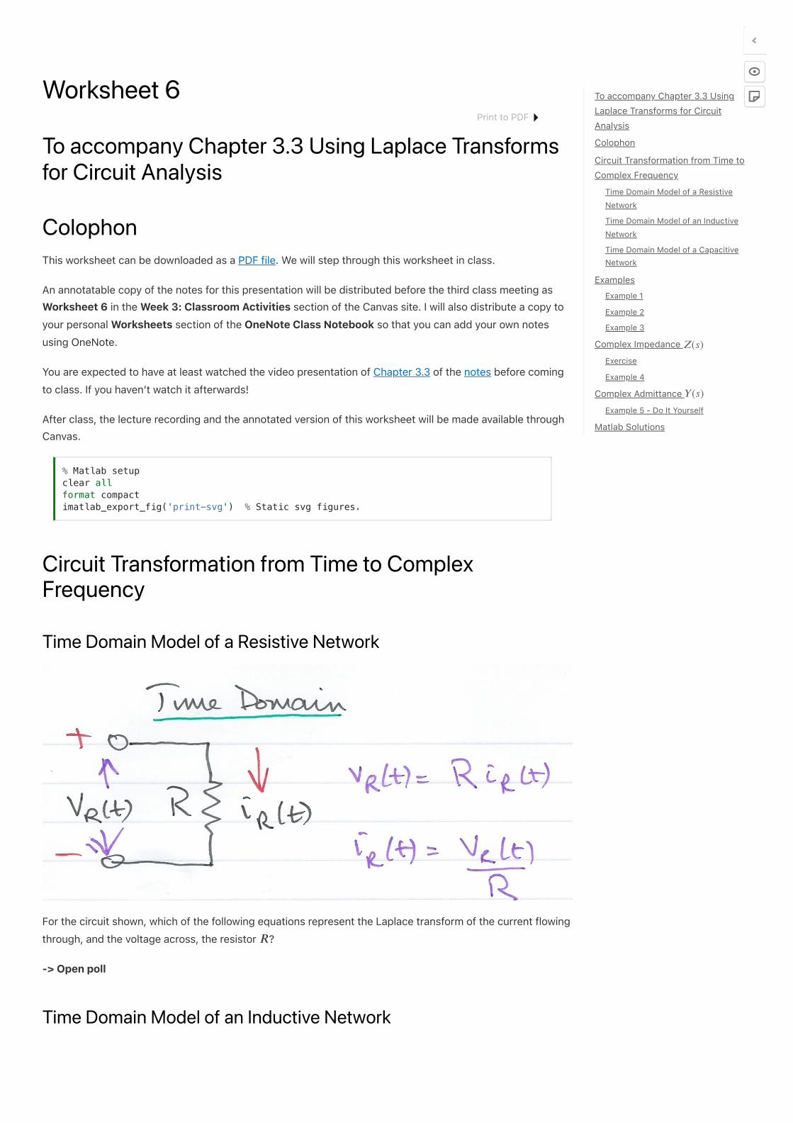
Time Domain Model of a Resistive Network
For the circuit shown, which of the following equations represent the Laplace transform of the current flowing
through, and the voltage across, the resistor ?
-> Open poll
Time Domain Model of an Inductive Network
% Matlab setup clear all format compact imatlab_export_fig('print-svg') % Static svg figures.
𝑅
To accompany Chapter 3.3 Using
Laplace Transforms for Circuit
Analysis
Colophon
Circuit Transformation from Time to
Complex Frequency
Time Domain Model of a Resistive
Network
Time Domain Model of an Inductive
Network
Time Domain Model of a Capacitive
Network
Examples
Example 1
Example 2
Example 3
Complex Impedance
Exercise
Example 4
Complex Admittance
Example 5 - Do It Yourself
Matlab Solutions
𝑍(𝑠)
𝑌 (𝑠)
Print to PDF
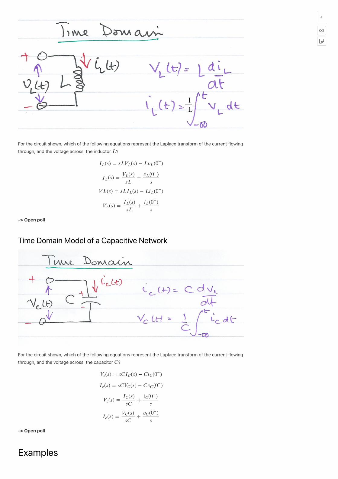
For the circuit shown, which of the following equations represent the Laplace transform of the current flowing
through, and the voltage across, the inductor ?
-> Open poll
Time Domain Model of a Capacitive Network
For the circuit shown, which of the following equations represent the Laplace transform of the current flowing
through, and the voltage across, the capacitor ?
-> Open poll
Examples
𝐿
(𝑠) = 𝑠𝐿 (𝑠) − 𝐿 ( )𝐼𝐿 𝑉𝐿 𝑣𝐿 0−
(𝑠) = +𝐼𝐿
(𝑠)𝑉𝐿
𝑠𝐿
( )𝑣𝐿 0−
𝑠
𝑉 𝐿(𝑠) = 𝑠𝐿 (𝑠) − 𝐿 ( )𝐼𝐿 𝑖𝐿 0−
(𝑠) = +𝑉𝐿
(𝑠)𝐼𝐿
𝑠𝐿
( )𝑖𝐿 0−
𝑠
𝐶
(𝑠) = 𝑠𝐶 (𝑠) − 𝐶 ( )𝑉𝑐 𝐼𝐶 𝑖𝐶 0−
(𝑠) = 𝑠𝐶 (𝑠) − 𝐶 ( )𝐼𝑐 𝑉𝐶 𝑣𝐶 0−
(𝑠) = +𝑉𝑐
(𝑠)𝐼𝐶
𝑠𝐶
( )𝑖𝐶 0−
𝑠
(𝑠) = +𝐼𝑐
(𝑠)𝑉𝐶
𝑠𝐶
( )𝑣𝐶 0−
𝑠
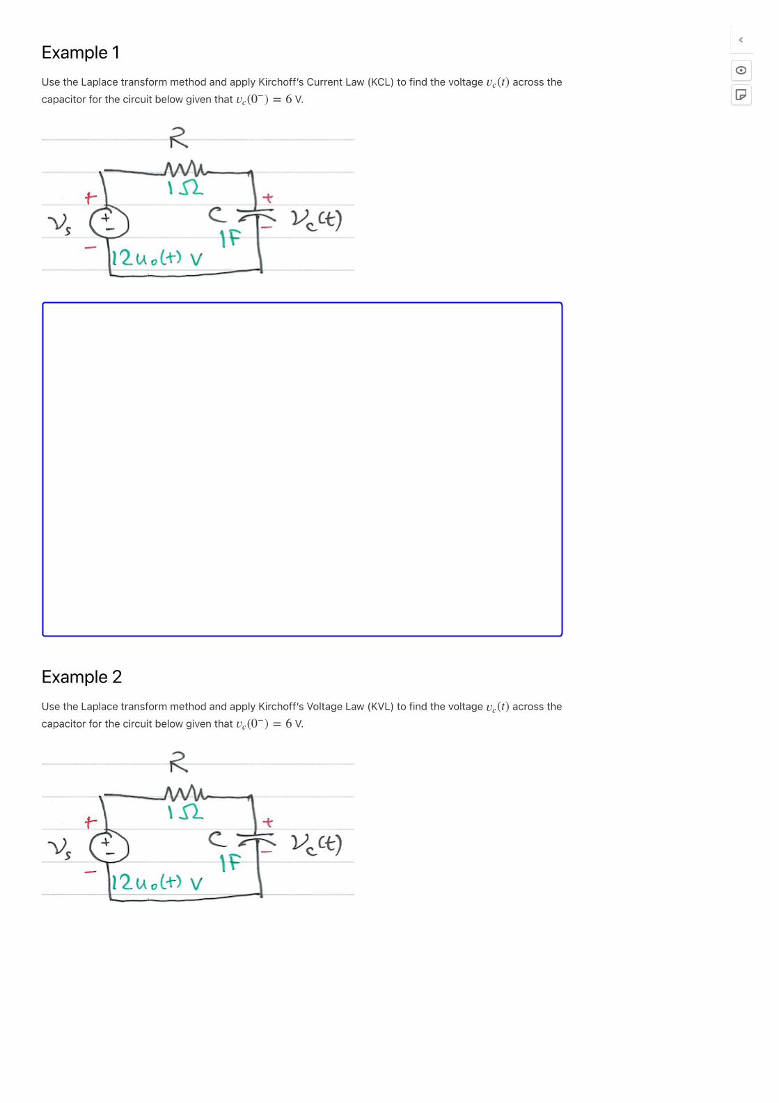
Example 1
Use the Laplace transform method and apply Kirchoff s̓ Current Law (KCL) to find the voltage across the
capacitor for the circuit below given that V.
Example 2
Use the Laplace transform method and apply Kirchoff s̓ Voltage Law (KVL) to find the voltage across the
capacitor for the circuit below given that V.
(𝑡)𝑣𝑐
( ) = 6𝑣𝑐 0−
(𝑡)𝑣𝑐
( ) = 6𝑣𝑐 0−
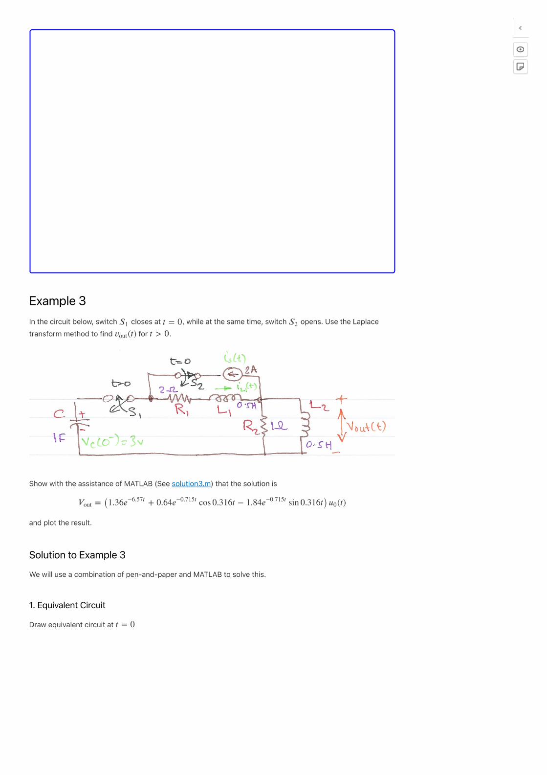
Example 3
In the circuit below, switch closes at , while at the same time, switch opens. Use the Laplace
transform method to find for .
Show with the assistance of MATLAB (See solution3.m) that the solution is
and plot the result.
Solution to Example 3
We will use a combination of pen-and-paper and MATLAB to solve this.
1. Equivalent Circuit
Draw equivalent circuit at
𝑆1 𝑡 = 0 𝑆2
(𝑡)𝑣out 𝑡 > 0
= (1.36 + 0.64 cos 0.316𝑡 − 1.84 sin 0.316𝑡) (𝑡)𝑉out 𝑒−6.57𝑡
𝑒−0.715𝑡
𝑒−0.715𝑡
𝑢0
𝑡 = 0
2. Transform model
Convert to transforms
3. Determine equation
Determine equation for .(𝑠)𝑉out
4. Complete solution in MATLAB
In the lecture we showed that after simplification for Example 3
We will use MATLAB to factorize the denominator of the equation into a linear and a quadratic factor.
Find roots of Denominator D(s)
Find quadratic form
Simplify coefficients of s
Complete the Square
=𝑉out
2𝑠(𝑠 + 3)
+ 8 + 10𝑠 + 4𝑠3 𝑠2
𝐷(𝑠)
r = roots([1, 8, 10, 4])
syms s t y = expand((s - r(2))*(s - r(3)))
y = sym2poly(y)
Plot result
Worked Solution: Example 3
File Pencast: example3.pdf - Download and open in Adobe Acrobat Reader.
The attached “PenCast” works through the solution to Example 3 by hand. It s̓ quite a complex, error-prone
(as you will see!) calculation that needs careful attention to detail. This in itself gives justification to my belief
that you should use computers wherever possible.
Please note, the PenCast takes around 39 minutes (I said it was a complex calculation) but you can fast
forward and replay any part of it.
Alternative solution using transfer functions
Complex Impedance For the resistance , inductance H and capacitance F, which of the following represent the complex
impedance of the components?
-> Open Poll
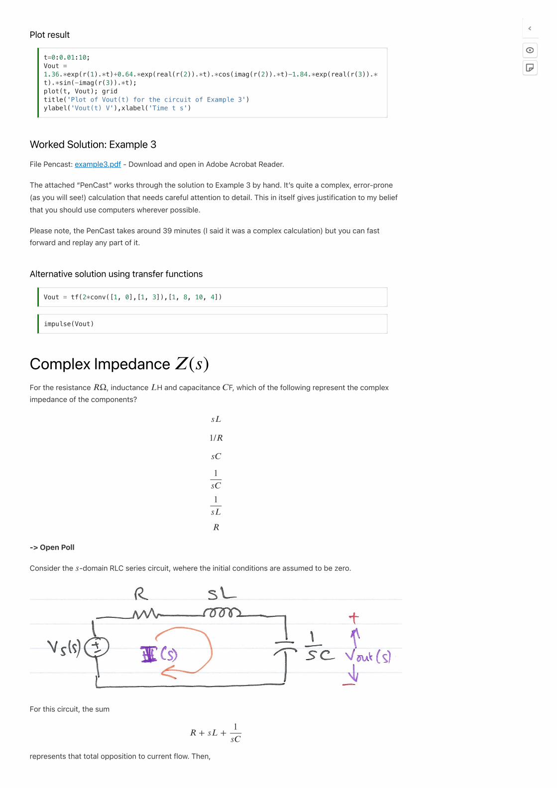
Consider the -domain RLC series circuit, wehere the initial conditions are assumed to be zero.
For this circuit, the sum
represents that total opposition to current flow. Then,
t=0:0.01:10; Vout = 1.36.*exp(r(1).*t)+0.64.*exp(real(r(2)).*t).*cos(imag(r(2)).*t)-1.84.*exp(real(r(3)).*t).*sin(-imag(r(3)).*t); plot(t, Vout); grid title('Plot of Vout(t) for the circuit of Example 3') ylabel('Vout(t) V'),xlabel('Time t s')
Vout = tf(2*conv([1, 0],[1, 3]),[1, 8, 10, 4])
impulse(Vout)
𝑍(𝑠)
𝑅Ω 𝐿 𝐶
𝑠𝐿
1/𝑅
𝑠𝐶
1
𝑠𝐶
1
𝑠𝐿
𝑅
𝑠
𝑅 + 𝑠𝐿 +1
𝑠𝐶
and defining the ratio as , we obtain
The -domain current can be found from
where
Since is a complex number, is also complex and is known as the complex input impedance
of this RLC series circuit.
Exercise
Use the previous result to give an expression for
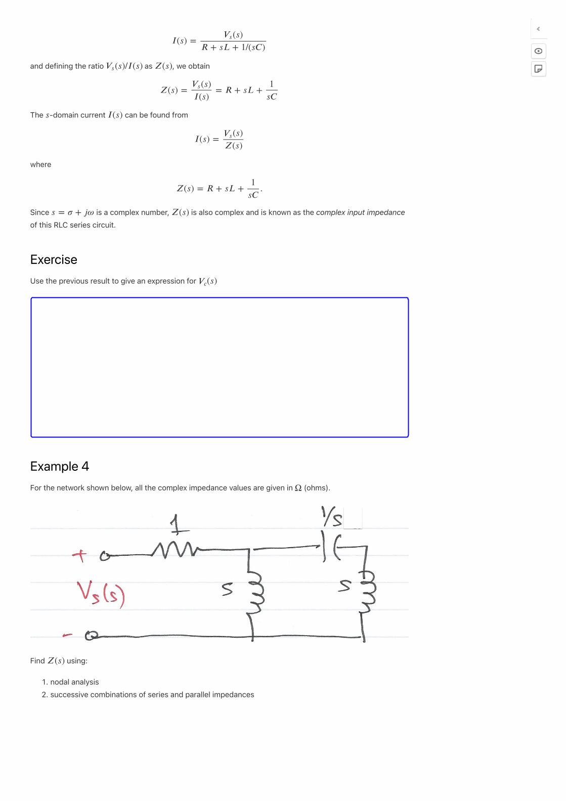
Example 4
For the network shown below, all the complex impedance values are given in (ohms).
Find using:
�. nodal analysis
�. successive combinations of series and parallel impedances
𝐼(𝑠) =(𝑠)𝑉𝑠
𝑅 + 𝑠𝐿 + 1/(𝑠𝐶)
(𝑠)/𝐼(𝑠)𝑉𝑠 𝑍(𝑠)
𝑍(𝑠) = = 𝑅 + 𝑠𝐿 +(𝑠)𝑉𝑠
𝐼(𝑠)
1
𝑠𝐶
𝑠 𝐼(𝑠)
𝐼(𝑠) =(𝑠)𝑉𝑠
𝑍(𝑠)
𝑍(𝑠) = 𝑅 + 𝑠𝐿 + .1
𝑠𝐶
𝑠 = 𝜎 + 𝑗𝜔 𝑍(𝑠)
(𝑠)𝑉𝑐
Ω
𝑍(𝑠)
Solutions: Pencasts ex4_1.pdf and ex4_2.pdf – open in Adobe Acrobat.
Complex Admittance For the resistor Ω, inductor H and capacitance F, which of the following represent the complex
admittance of the components?
-> Open Poll
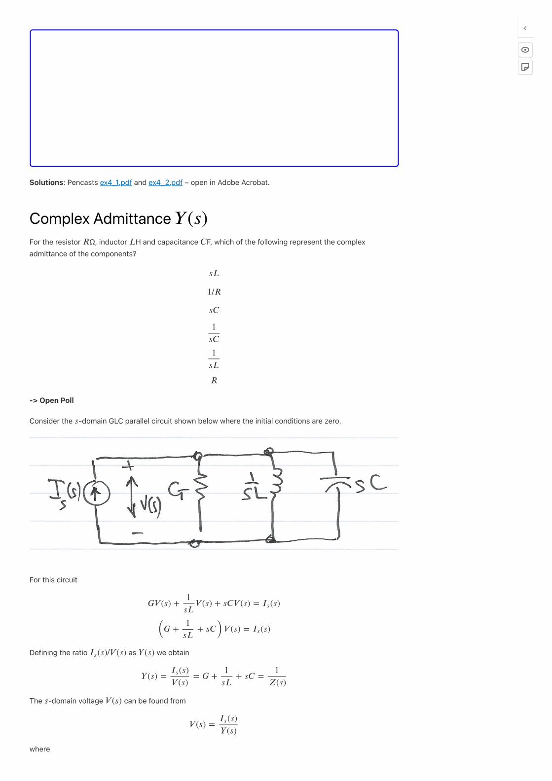
Consider the -domain GLC parallel circuit shown below where the initial conditions are zero.
For this circuit
Defining the ratio as we obtain
The -domain voltage can be found from
where
𝑌 (𝑠)
𝑅 𝐿 𝐶
𝑠𝐿
1/𝑅
𝑠𝐶
1
𝑠𝐶
1
𝑠𝐿
𝑅
𝑠
𝐺𝑉 (𝑠) + 𝑉 (𝑠) + 𝑠𝐶𝑉 (𝑠) = (𝑠)1
𝑠𝐿𝐼𝑠
(𝐺 + + 𝑠𝐶)𝑉 (𝑠) = (𝑠)1
𝑠𝐿𝐼𝑠
(𝑠)/𝑉 (𝑠)𝐼𝑠 𝑌 (𝑠)
𝑌 (𝑠) = = 𝐺 + + 𝑠𝐶 =(𝑠)𝐼𝑠
𝑉 (𝑠)
1
𝑠𝐿
1
𝑍(𝑠)
𝑠 𝑉 (𝑠)
𝑉 (𝑠) =(𝑠)𝐼𝑠
𝑌 (𝑠)
is complex and is known as the complex input admittance of this GLC parallel circuit.
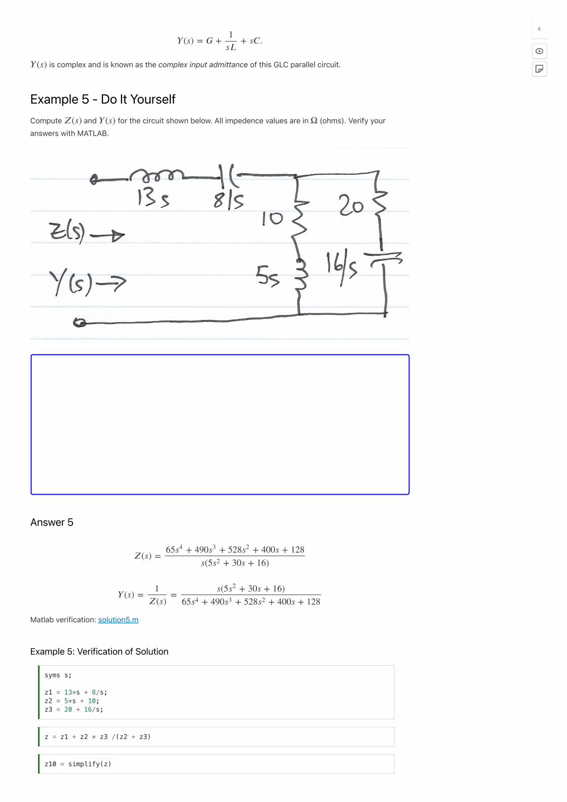
Example 5 - Do It Yourself
Compute and for the circuit shown below. All impedence values are in (ohms). Verify your
answers with MATLAB.
Answer 5
Matlab verification: solution5.m
Example 5: Verification of Solution
𝑌 (𝑠) = 𝐺 + + 𝑠𝐶.1
𝑠𝐿
𝑌 (𝑠)
𝑍(𝑠) 𝑌 (𝑠) Ω
𝑍(𝑠) =65 + 490 + 528 + 400𝑠 + 128𝑠4 𝑠3 𝑠2
𝑠(5 + 30𝑠 + 16)𝑠2
𝑌 (𝑠) = =1
𝑍(𝑠)
𝑠(5 + 30𝑠 + 16)𝑠2
65 + 490 + 528 + 400𝑠 + 128𝑠4 𝑠3 𝑠2
syms s; z1 = 13*s + 8/s; z2 = 5*s + 10; z3 = 20 + 16/s;
z = z1 + z2 * z3 /(z2 + z3)
z10 = simplify(z)

By Dr Chris P. Jobling
© Copyright Swansea University (2019-2022).
This page was created by Dr Chris P. Jobling for Swansea University .
Admittance
Matlab SolutionsFor convenience, single script MATLAB solutions to the examples are provided and can be downloaded from
the accompanying MATLAB folder in the GitHub repository.
Solution 3 [solution3.m]
Solution 5 [solution5.m]
pretty(z10)
y10 = 1/z10; pretty(y10)
cd ../matlab ls open solution3 open solution5